Embed Size (px)
Citation preview
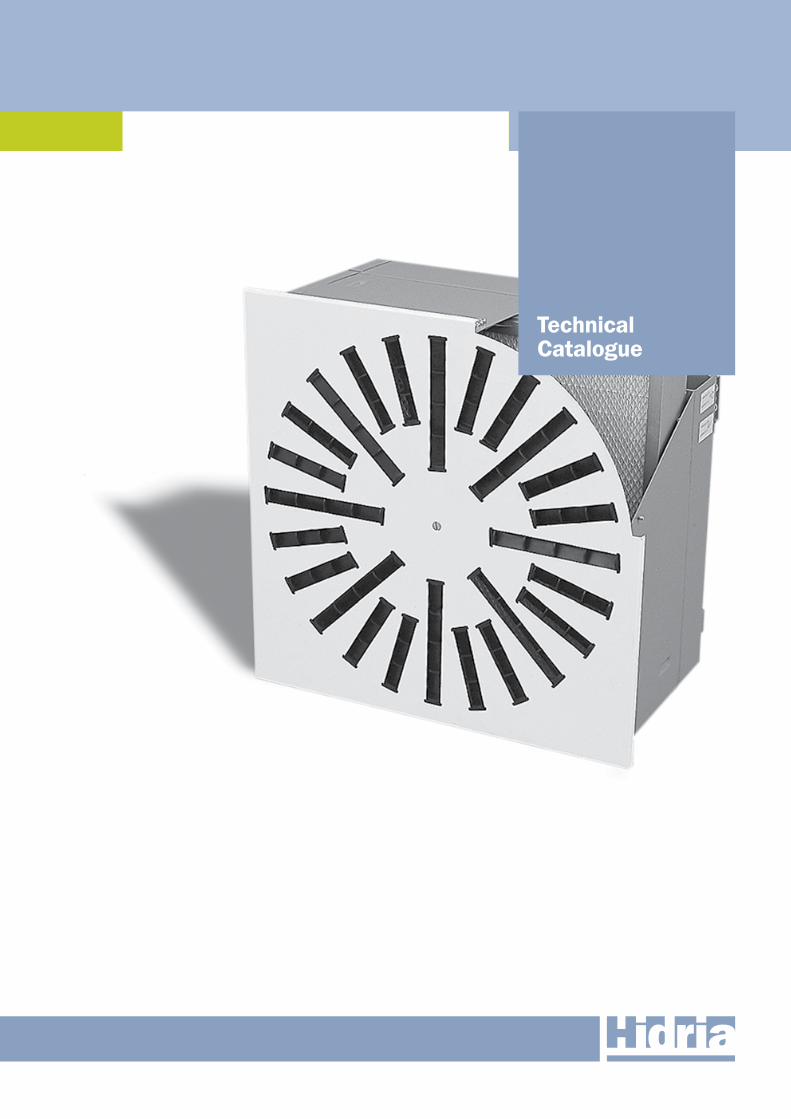
Absolute air filtration
Technical Catalogue
Overview
2
Absolute air filtration
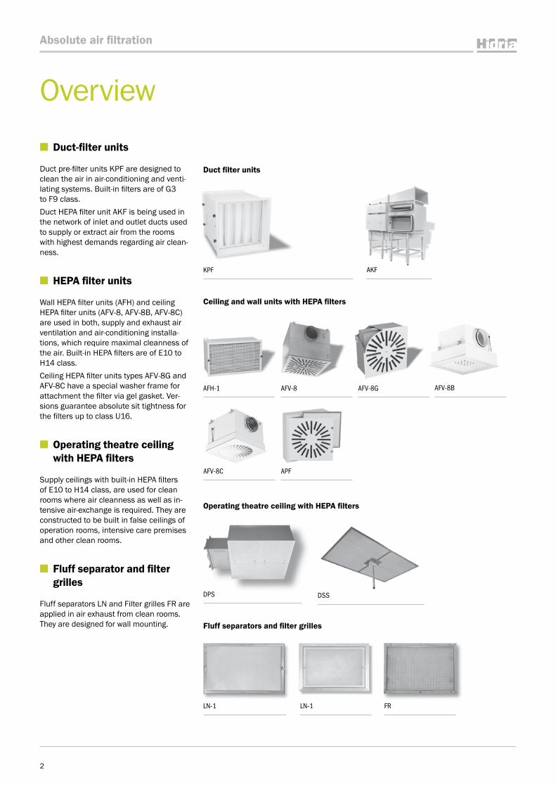
■ Duct-filter units
Duct pre-filter units KPF are designed to clean the air in air-conditioning and venti-lating systems. Built-in filters are of G3 to F9 class. Duct HEPA filter unit AKF is being used in the network of inlet and outlet ducts used to supply or extract air from the rooms with highest demands regarding air clean-ness.
■ HEPA filter units
Wall HEPA filter units (AFH) and ceiling HEPA filter units (AFV-8, AFV-8B, AFV-8C) are used in both, supply and exhaust air ventilation and air-conditioning installa-tions, which require maximal cleanness of the air. Built-in HEPA filters are of E10 to H14 class. Ceiling HEPA filter units types AFV-8G and AFV-8C have a special washer frame for attachment the filter via gel gasket. Ver-sions guarantee absolute sit tightness for the filters up to class U16.
■ Operating theatre ceiling with HEPA filters
Supply ceilings with built-in HEPA filters of E10 to H14 class, are used for clean rooms where air cleanness as well as in-tensive air-exchange is required. They are constructed to be built in false ceilings of operation rooms, intensive care premises and other clean rooms.
■ Fluff separator and filter grilles
Fluff separators LN and Filter grilles FR are applied in air exhaust from clean rooms. They are designed for wall mounting.
KPF AKF
LN-1 LN-1 FR
AFV-8C APF
Duct filter units
Ceiling and wall units with HEPA filters
Operating theatre ceiling with HEPA filters
Fluff separators and filter grilles
AFH-1 AFV-8 AFV-8G AFV-8B
DPS DSS
Content
■ Legend of symbols
St Element is made of steel sheet. Element for air conditioning of rooms with floor to ceiling heights room up to 4 m.
RAL9010
Element is powder painted in stand-ard RAL 9010 colour. Other desired colour is to be specified in the order.
M Element allows regulation by electric motor (Belimo electric motors).
CD
INOX The element is made of stainless sheet steel AISI 304.
Element is intended to be built in the wall.
FEU...
Element is intended for air filtration. The filter of class … is built in.
AI Element is made of aluminium pro-files, aluminium sheet or aluminium casting.
Element is intended to be built in the ceiling or in the wall.
F Element is intended for air filtration. Filter is not included.
The possibility of the automatic selection and calculation of the technical characteristics of grilles and difusers in regard to the given conditions with the assistance of the Klima ADE program.
Page
DUCT FILTER UNITS 4
Duct pre-filter units KPF 4
Duct HEPA filter units AKF 6
CEILING AND WALL HEPA FILTER UNITS 11
Wall HEPA filter units AFH-1 11
Ceiling HEPA filter units with flat gasket AFV-8 13
Ceiling HEPA filter units with semicircular or U-shaped gasket AFV-8B 17
Ceiling HEPA filter unit with semicircular or gel gasket AFV-8C 22
Ceiling HEPA filter units with gel gasket AFV-8G 27
Ceiling diffuser with pre-filter APF 31
OPERATING THEATRE CEILINGS 32
Operating theatre ceiling – perforated version DPS 32
Operating theatre ceiling – textile version DSS 34
FLUFF SEPARATOR 37
Fluff separator LN-1 37
Fluff separator LN-2 38
FILTER GRILLE 39
Filter grille FR 39
FILTERS 40
EPA, HEPA, ULPA filters 41
BAG filters 45
Panel filters 46
ACCESSORIES 48
3
Absolute air filtration
Duct filter units
St
RAL9010
FEU...
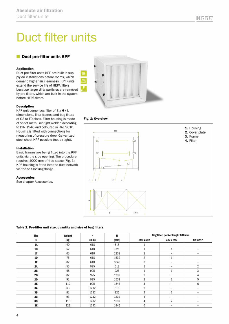
Fig. 1: Overview
4
Absolute air filtrationDuct filter units
Table 1: Pre-filter unit size, quantity and size of bag filters
■ Duct pre-filter units KPF
Application Duct pre-filter units KPF are built in sup-ply air installations before rooms, which demand higher air cleanness. KPF units extend the service life of HEPA filters, because larger dirty particles are removed by pre-filters, which are built in the system before HEPA filters.
DescriptionKPF unit comprises filter of B x H x L dimensions, filter frames and bag filters of G3 to F9 class. Filter housing is made of sheet metal, air-tight welded according to DIN 1946 and coloured in RAL 9010. Housing is fitted with connections for measuring of pressure drop. Galvanized steel sheet KPF possible (not airtight).
InstallationBasic frames are being fitted into the KPF units via the side opening. The procedure requires 1000 mm of free space (Fig. 1). KPF housing is fitted into the duct network via the self-locking flange.
AccessoriesSee chapter Accessories.
1. Housing 2. Cover plate3. Frame4. Filter
Sizex
Weight(kg)
H(mm)
B(mm)
Bag filter, pocket lenght 630 mm592 x 592 287 x 592 87 x 287
1A 40 618 618 1 –1B 52 618 925 1 1 –1C 63 618 1232 2 – –1D 75 618 1539 2 1 –1E 82 618 1846 3 – –2A 53 925 618 1 – 22B 68 925 925 1 1 32C 82 925 1232 2 – 42D 91 925 1539 2 1 52E 110 925 1846 3 – 63A 63 1232 618 2 – –3B 81 1232 925 2 2 –3C 93 1232 1232 4 – –3D 110 1232 1539 4 2 –3E 123 1232 1846 6 – –
1000B
H
42
900
31
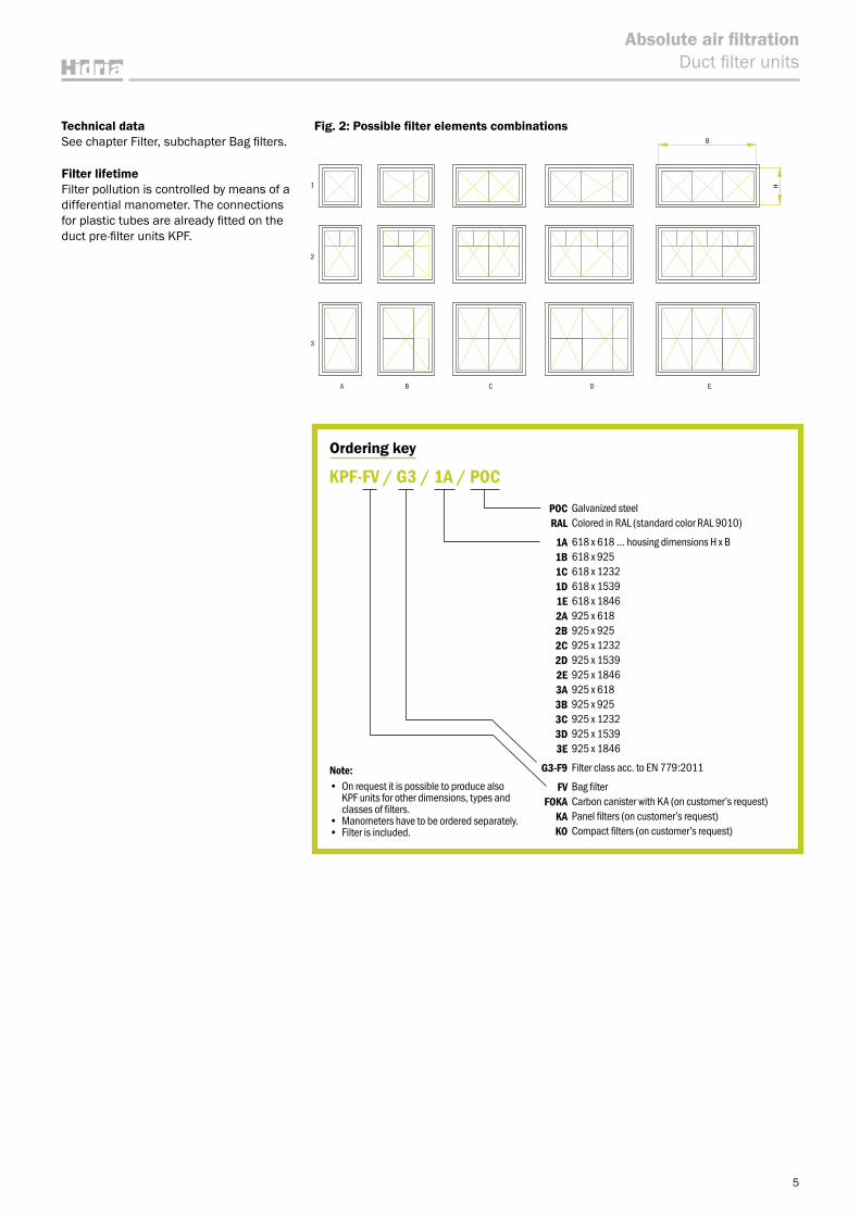
Ordering key
POC Galvanized steelRAL Colored in RAL (standard color RAL 9010)
1A 618 x 618 … housing dimensions H x B 1B 618 x 9251C 618 x 12321D 618 x 15391E 618 x 18462A 925 x 618 2B 925 x 9252C 925 x 12322D 925 x 15392E 925 x 18463A 925 x 618 3B 925 x 9253C 925 x 12323D 925 x 15393E 925 x 1846
G3-F9 Filter class acc. to EN 779:2011
FV Bag filterFOKA Carbon canister with KA (on customer’s request)
KA Panel filters (on customer’s request)KO Compact filters (on customer’s request)
KPF-FV / G3 / 1A / POC
Note:• On request it is possible to produce also
KPF units for other dimensions, types and classes of filters.
• Manometers have to be ordered separately.• Filter is included.
5
Absolute air filtrationDuct filter units
Technical dataSee chapter Filter, subchapter Bag filters.
Filter lifetimeFilter pollution is controlled by means of a differential manometer. The connections for plastic tubes are already fitted on the duct pre-filter units KPF.
Fig. 2: Possible filter elements combinationsB
H
EDCBA
3
2
1
6
Absolute air filtrationDuct filter units
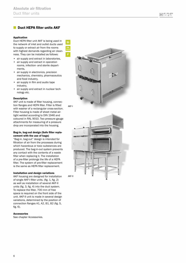
■ Duct HEPA filter units AKF
ApplicationDuct HEPA filter unit AKF is being used in the network of inlet and outlet ducts used to supply or extract air from the rooms with highest demands regarding air clean-ness. They can be installed as follows:• air supply and extract in laboratories, • air supply and extract in operation
rooms, infection- and sterile depart-ments,
• air supply in electronics, precision mechanics, chemistry, pharmaceutics and food industry,
• air supply in film and audio tape industry,
• air supply and extract in nuclear tech-nology etc.
DescriptionAKF unit is made of filter housing, connec-tion flanges and HEPA filter. Filter is fitted with washer of a rectangular cross-section. Filter housing is made of sheet metal air-tight welded according to DIN 1946 and coloured in RAL 9010. Two pressure gauge attachments for measuring of a pressure drop are incorporated into the housing.
Bag-in, bag-out design (Safe filter repla-cement with the use of bags)“Bag-in, bag-out“ design is intended for filtration of air from the processes during which hazardous or toxic substances are produced. The bag-in-out system prevents any contact with the contents of a waste filter when replacing it. The installation of a pre-filter prolongs the life of a HEPA filter. The system of pre-filter replacement is the same as HEPA filter replacement.
Installation and design variationsAKF housing are designed for installation of single AKF-I filter units. (fig. 1, fig. 2) as well as installation of several AKF-II units (fig. 3, fig. 4) into the duct system. To replace the filter, 700 mm of free space is required on the front side of the unit. AKF-II unit is made in several design variations, determined by the position of connection flanges A1, A2, B1, B2 (fig. 5, fig. 6).
AccessoriesSee chapter Accessories.
AKF-II
AKF-I
St
RAL9010
F
7
Absolute air filtrationDuct filter units
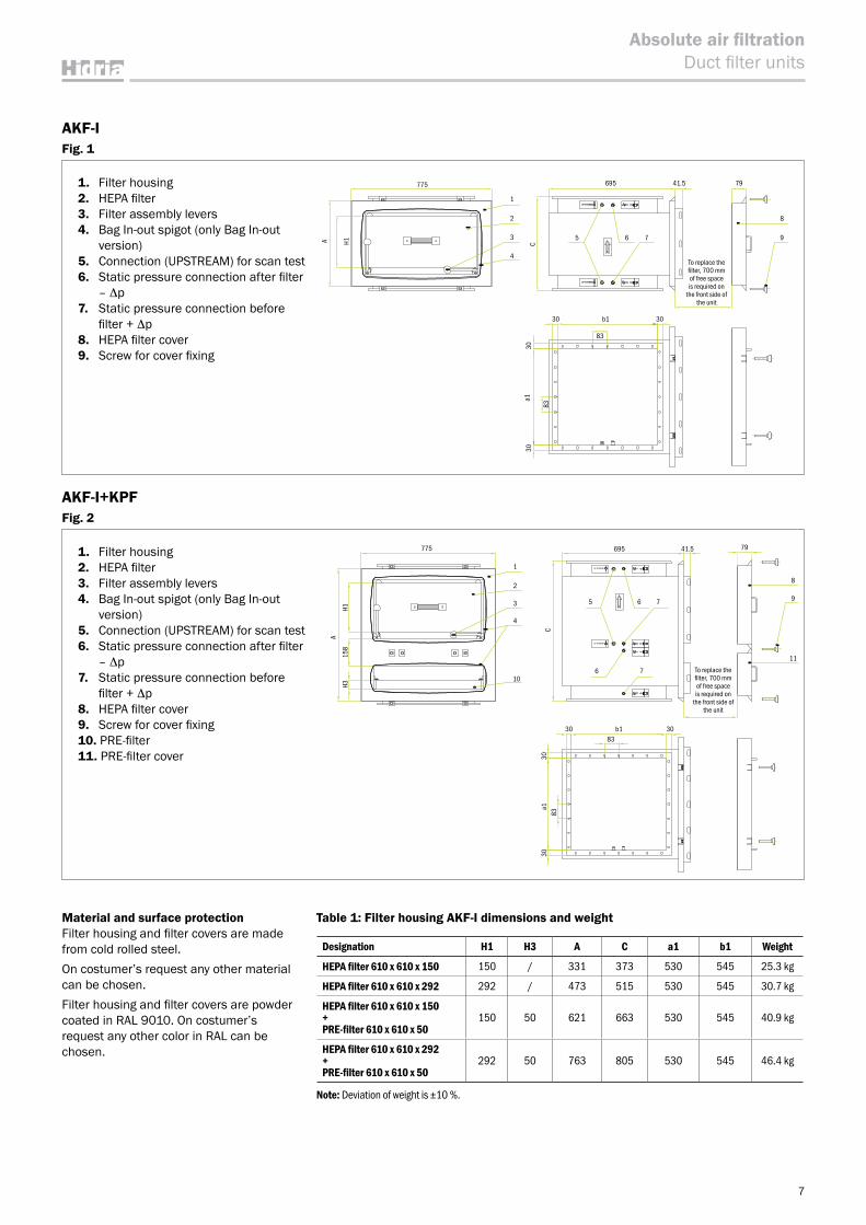
AKF-IFig. 1
AKF-I+KPF Fig. 2
Material and surface protectionFilter housing and filter covers are made from cold rolled steel.On costumer’s request any other material can be chosen.Filter housing and filter covers are powder coated in RAL 9010. On costumer’s request any other color in RAL can be chosen.
Table 1: Filter housing AKF-I dimensions and weight
Designation H1 H3 A C a1 b1 Weight
HEPA filter 610 x 610 x 150 150 / 331 373 530 545 25.3 kg
HEPA filter 610 x 610 x 292 292 / 473 515 530 545 30.7 kg
HEPA filter 610 x 610 x 150 + PRE-filter 610 x 610 x 50
150 50 621 663 530 545 40.9 kg
HEPA filter 610 x 610 x 292 + PRE-filter 610 x 610 x 50
292 50 763 805 530 545 46.4 kg
Note: Deviation of weight is ±10 %.
1. Filter housing2. HEPA filter3. Filter assembly levers4. Bag In-out spigot (only Bag In-out
version)5. Connection (UPSTREAM) for scan test6. Static pressure connection after filter
– Δp7. Static pressure connection before
filter + Δp8. HEPA filter cover9. Screw for cover fixing
To replace the filter, 700 mm of free space is required on
the front side of the unit
UP STREAM
UP STREAM
C
8
7941.5
9
30
30a1
30
b1 30
83
83
695
5 6 7
775
1
2
3
4
A H1
1. Filter housing2. HEPA filter3. Filter assembly levers4. Bag In-out spigot (only Bag In-out
version)5. Connection (UPSTREAM) for scan test6. Static pressure connection after filter
– Δp7. Static pressure connection before
filter + Δp8. HEPA filter cover9. Screw for cover fixing10. PRE-filter11. PRE-filter cover
A
To replace the filter, 700 mm of free space is required on
the front side of the unit
UP STREAM
UP STREAM
775
1
695
30 b183
83
30
79
8
11
9
C30
a130
2
3 5
6
6 7
7
4
10
H315
8H1
41.5
8
Absolute air filtrationDuct filter units
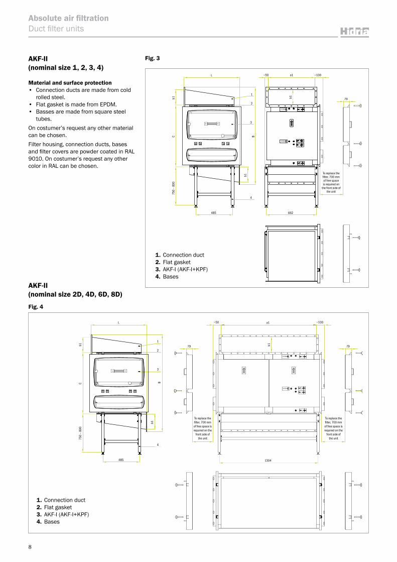
AKF-II (nominal size 1, 2, 3, 4)
Material and surface protection• Connection ducts are made from cold
rolled steel.• Flat gasket is made from EPDM.• Basses are made from square steel
tubes.On costumer’s request any other material can be chosen.Filter housing, connection ducts, bases and filter covers are powder coated in RAL 9010. On costumer’s request any other color in RAL can be chosen.
AKF-II (nominal size 2D, 4D, 6D, 8D)
Fig. 4
1. Connection duct2. Flat gasket3. AKF-I (AKF-I+KPF)4. Bases
1. Connection duct2. Flat gasket3. AKF-I (AKF-I+KPF)4. Bases
Fig. 3
To replace the filter, 700 mm of free space is required on
the front side of the unit
2
4
3
1
UP STREAM
UP STREAM
b1
B
~50 ~100a1L
b1
662485
750 -
800
Cb1 79
L
4
3
2
1
485 662
~50 ~100
79
a1
b1
b1
b1
BC75
0 –
800
To replace the filter, 700 mm of free space is required on the
front side of the unit
UP STREAM
UP STREAM
b1
L
4
3
2
1
485
~50 ~100
7979
a1
b1
b1
b1
BC75
0 –
800
To replace the filter, 700 mm of free space is required on the
front side of the unit
L
1304
9
Absolute air filtrationDuct filter units
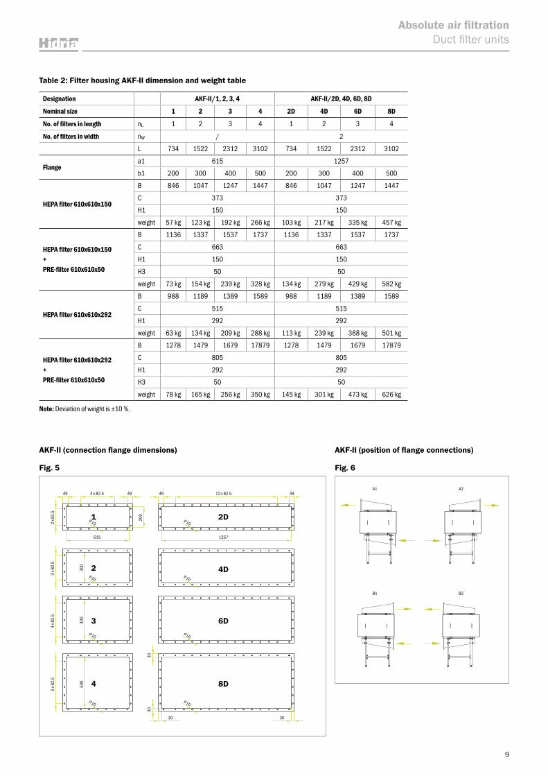
AKF-II (connection flange dimensions)
Fig. 5
AKF-II (position of flange connections)
Fig. 6
Table 2: Filter housing AKF-II dimension and weight table
Designation AKF-II/1, 2, 3, 4 AKF-II/2D, 4D, 6D, 8D
Nominal size 1 2 3 4 2D 4D 6D 8D
No. of filters in length nL 1 2 3 4 1 2 3 4
No. of filters in width nW / 2
L 734 1522 2312 3102 734 1522 2312 3102
Flangea1 615 1257
b1 200 300 400 500 200 300 400 500
HEPA filter 610x610x150
B 846 1047 1247 1447 846 1047 1247 1447
C 373 373
H1 150 150
weight 57 kg 123 kg 192 kg 266 kg 103 kg 217 kg 335 kg 457 kg
HEPA filter 610x610x150+PRE-filter 610x610x50
B 1136 1337 1537 1737 1136 1337 1537 1737
C 663 663
H1 150 150
H3 50 50
weight 73 kg 154 kg 239 kg 328 kg 134 kg 279 kg 429 kg 582 kg
HEPA filter 610x610x292
B 988 1189 1389 1589 988 1189 1389 1589
C 515 515
H1 292 292
weight 63 kg 134 kg 209 kg 288 kg 113 kg 239 kg 368 kg 501 kg
HEPA filter 610x610x292+PRE-filter 610x610x50
B 1278 1479 1679 17879 1278 1479 1679 17879
C 805 805
H1 292 292
H3 50 50
weight 78 kg 165 kg 256 kg 350 kg 145 kg 301 kg 473 kg 626 kg
Note: Deviation of weight is ±10 %.
A1 A2 B1 B2
A1 A2 B1 B2
A1
B1
A2
B2
200
300
400
500
2x82
.53x
82.5
4x82
.55x
82.5
4x82.5 4949 49 49
615 1257
12x82.5
3030
3030
1
2
3
4
2D
4D
6D
8D
∅10∅10
∅10∅10
∅10∅10
∅10∅10
615 1257
4 x 82.5 12 x 82.5
2D1
2
3
4
4D
6D
8D
49 49 4949
2 x 8
2.5
3030
30 30
3 x 8
2.5
4 x 8
2.5
5 x 8
2.5
200
300
400
500
Ordering key
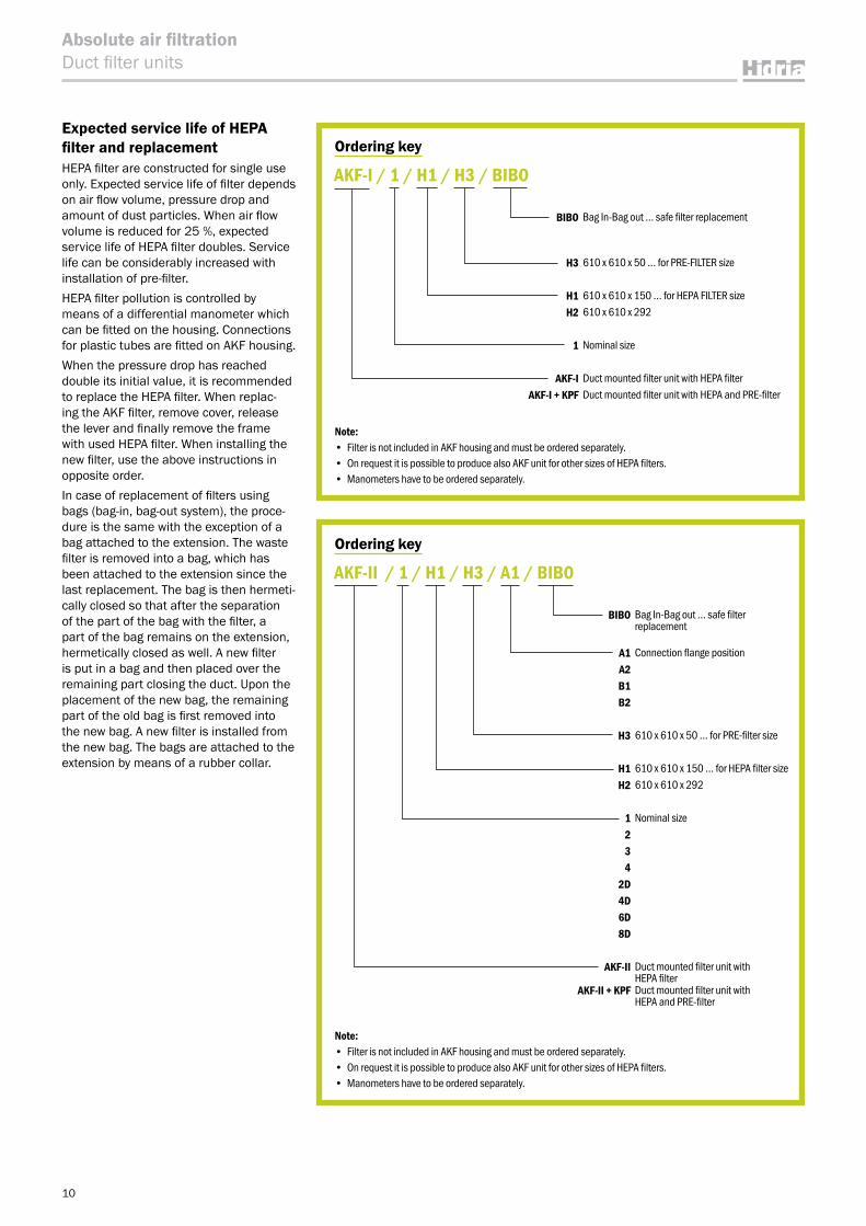
BIBO Bag In-Bag out … safe filter replacement
H3 610 x 610 x 50 … for PRE-FILTER size
H1 610 x 610 x 150 … for HEPA FILTER sizeH2 610 x 610 x 292
1 Nominal size
AKF-I Duct mounted filter unit with HEPA filterAKF-I + KPF Duct mounted filter unit with HEPA and PRE-filter
AKF-I / 1 / H1 / H3 / BIBO
Note:• Filter is not included in AKF housing and must be ordered separately.• On request it is possible to produce also AKF unit for other sizes of HEPA filters. • Manometers have to be ordered separately.
Ordering key
Note:• Filter is not included in AKF housing and must be ordered separately.• On request it is possible to produce also AKF unit for other sizes of HEPA filters. • Manometers have to be ordered separately.
BIBO Bag In-Bag out … safe filter replacement
A1 Connection flange position A2B1B2
H3 610 x 610 x 50 … for PRE-filter size
H1 610 x 610 x 150 … for HEPA filter sizeH2 610 x 610 x 292
1 Nominal size234
2D4D6D8D
AKF-II Duct mounted filter unit with HEPA filter
AKF-II + KPF Duct mounted filter unit with HEPA and PRE-filter
AKF-II / 1 / H1 / H3 / A1 / BIBO
10
Absolute air filtrationDuct filter units
Expected service life of HEPA filter and replacementHEPA filter are constructed for single use only. Expected service life of filter depends on air flow volume, pressure drop and amount of dust particles. When air flow volume is reduced for 25 %, expected service life of HEPA filter doubles. Service life can be considerably increased with installation of pre-filter. HEPA filter pollution is controlled by means of a differential manometer which can be fitted on the housing. Connections for plastic tubes are fitted on AKF housing.When the pressure drop has reached double its initial value, it is recommended to replace the HEPA filter. When replac-ing the AKF filter, remove cover, release the lever and finally remove the frame with used HEPA filter. When installing the new filter, use the above instructions in opposite order. In case of replacement of filters using bags (bag-in, bag-out system), the proce-dure is the same with the exception of a bag attached to the extension. The waste filter is removed into a bag, which has been attached to the extension since the last replacement. The bag is then hermeti-cally closed so that after the separation of the part of the bag with the filter, a part of the bag remains on the extension, hermetically closed as well. A new filter is put in a bag and then placed over the remaining part closing the duct. Upon the placement of the new bag, the remaining part of the old bag is first removed into the new bag. A new filter is installed from the new bag. The bags are attached to the extension by means of a rubber collar.
Ceiling and wall HEPA filter units
St
RAL9010
F
11
Absolute air filtrationCeiling and wall HEPA filter units
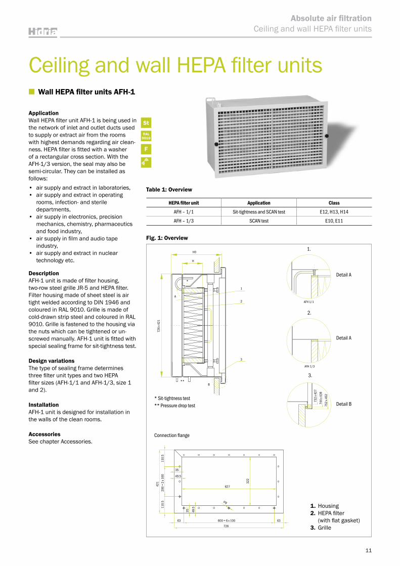
■ Wall HEPA filter units AFH-1
ApplicationWall HEPA filter unit AFH-1 is being used in the network of inlet and outlet ducts used to supply or extract air from the rooms with highest demands regarding air clean-ness. HEPA filter is fitted with a washer of a rectangular cross section. With the AFH-1/3 version, the seal may also be semi-circular. They can be installed as follows:• air supply and extract in laboratories, • air supply and extract in operating
rooms, infection- and sterile departments,
• air supply in electronics, precision mechanics, chemistry, pharmaceutics and food industry,
• air supply in film and audio tape industry,
• air supply and extract in nuclear technology etc.
DescriptionAFH-1 unit is made of filter housing, two-row steel grille JR-5 and HEPA filter. Filter housing made of sheet steel is air tight welded according to DIN 1946 and coloured in RAL 9010. Grille is made of cold-drawn strip steel and coloured in RAL 9010. Grille is fastened to the housing via the nuts which can be tightened or un-screwed manually. AFH-1 unit is fitted with special sealing frame for sit-tightness test.
Design variationsThe type of sealing frame determines three filter unit types and two HEPA filter sizes (AFH-1/1 and AFH-1/3, size 1 and 2).
InstallationAFH-1 unit is designed for installation in the walls of the clean rooms.
AccessoriesSee chapter Accessories.
Table 1: Overview
HEPA filter unit Application Class
AFH ‒ 1/1 Sit-tightness and SCAN test E12, H13, H14
AFH ‒ 1/3 SCAN test E10, E11
1. Housing2. HEPA filter
(with flat gasket)3. Grille
Fig. 1: Overview
* Sit-tightness test ** Pressure drop test
Connection flange
Detail A
Detail A
Detail B
1.
2.
3.
H0
H
A
B
726
x 421
732
x 427
744
x 439
752
x 452
1
2
3
**
*
AFH 1/1
AFH 1/3
627
322
∅9
35
35
63 63600 = 6 x 100
726
110.
5
421
110.
520
0 =
2 x 1
00 49.5
49.5
12
Absolute air filtrationCeiling and wall HEPA filter units
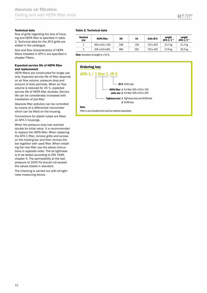
Technical dataSize of grille regarding the size of hous-ing and HEPA filter is specified in table 2. Technical data for the JR-5 grille are stated in the catalogue.Size and flow characteristics of HEPA filters installed in AFH-1 are specified in chapter Filters.
Expected service life of HEPA filter and replacement HEPA filters are constructed for single use only. Expected service life of filter depends on air flow volume, pressure drop and amount of dust particles. When air flow volume is reduced for 25 %, expected service life of HEPA filter doubles. Service life can be considerably increased with installation of pre-filter. Absolute filter pollution can be controlled by means of a differential manometer which can be fitted on the housing.Connections for plastic tubes are fitted on AFH-1 housings. When the pressure drop has reached double its initial value, it is recommended to replace the HEPA filter. When replacing the AFH-1 filter, remove grille and screws on the holding bar and then remove the bar together with used filter. When install-ing the new filter use the above instruc-tions in opposite order. The sit tightness is to be tested according to DIN 1946, chapter 4. The permeability at the test pressure of 2000 Pa should not exceed the values stated in standard. The checking is carried out with sit-tight-ness measuring device.
Ordering key
JR-5 Grille type
HEPA filter 1 For filter 305 x 610 x 150units size 2 For filter 305 x 610 x 292
Tightness test 1 Tightness test and SCAN test3 SCAN test
AFH-1 / 1 Size 1, JR-5
Note:Filter is not included and must be ordered separately.
Table 2: Technical data
Nominal size HEPA filter H0 H1 Grile JR-5 weight
AFH-1/1 *weight
AFH-1/3 *
1 305 x 610 x 150 338 150 725 x 425 23,7 kg 21,7 kg
2 305 x 610 x292 480 292 725 x 425 27,6 kg 25,5 kg
Note: Deviation of weight is ±10 %.
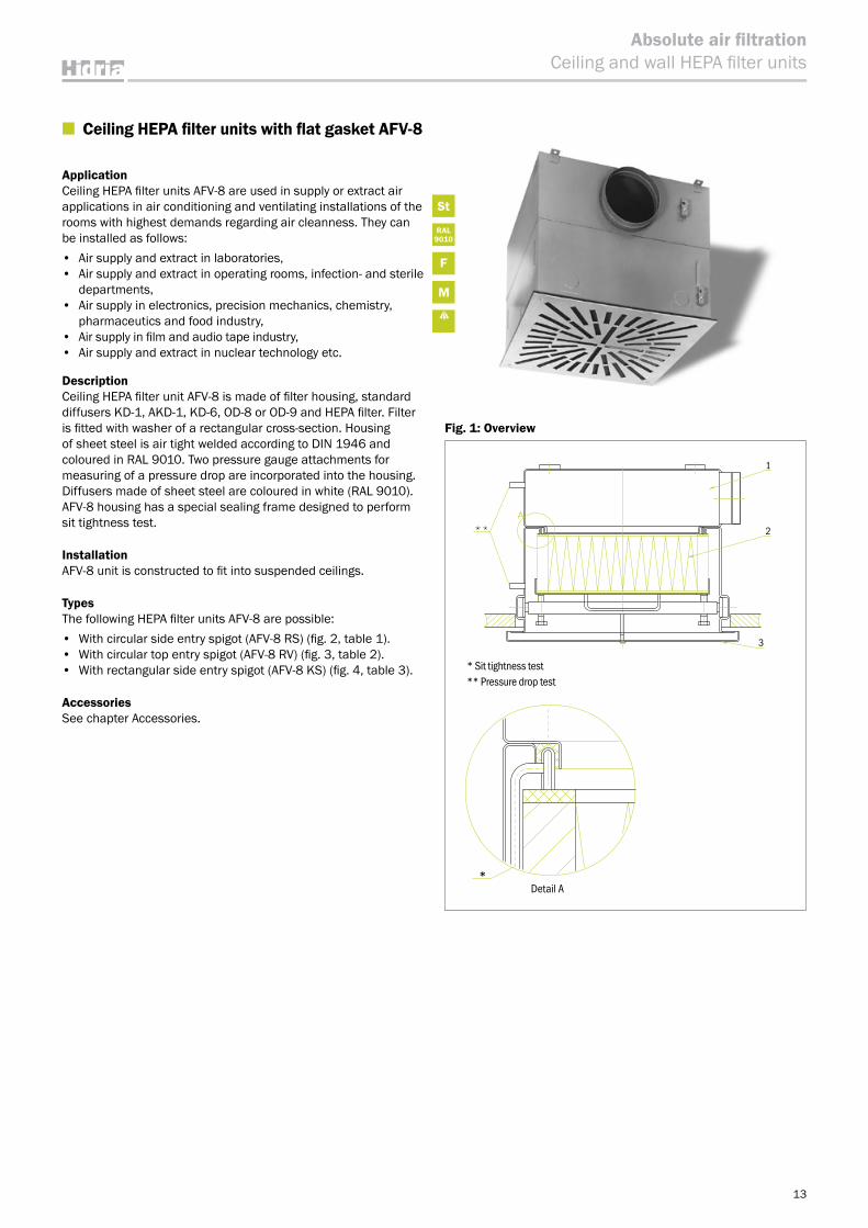
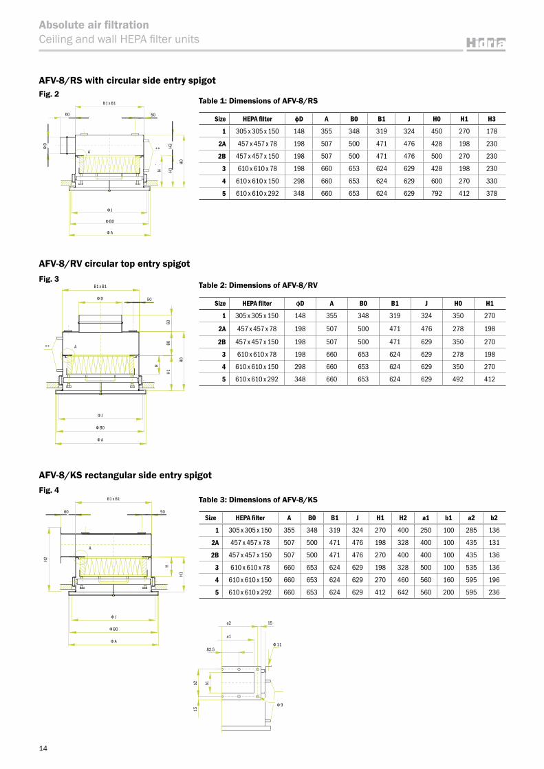
■ Ceiling HEPA filter units with flat gasket AFV-8
ApplicationCeiling HEPA filter units AFV-8 are used in supply or extract air applications in air conditioning and ventilating installations of the rooms with highest demands regarding air cleanness. They can be installed as follows:• Air supply and extract in laboratories,• Air supply and extract in operating rooms, infection- and sterile
departments, • Air supply in electronics, precision mechanics, chemistry,
pharmaceutics and food industry,• Air supply in film and audio tape industry,• Air supply and extract in nuclear technology etc.
DescriptionCeiling HEPA filter unit AFV-8 is made of filter housing, standard diffusers KD-1, AKD-1, KD-6, OD-8 or OD-9 and HEPA filter. Filter is fitted with washer of a rectangular cross-section. Housing of sheet steel is air tight welded according to DIN 1946 and coloured in RAL 9010. Two pressure gauge attachments for measuring of a pressure drop are incorporated into the housing. Diffusers made of sheet steel are coloured in white (RAL 9010). AFV-8 housing has a special sealing frame designed to perform sit tightness test.
InstallationAFV-8 unit is constructed to fit into suspended ceilings.
TypesThe following HEPA filter units AFV-8 are possible:• With circular side entry spigot (AFV-8 RS) (fig. 2, table 1).• With circular top entry spigot (AFV-8 RV) (fig. 3, table 2).• With rectangular side entry spigot (AFV-8 KS) (fig. 4, table 3).
AccessoriesSee chapter Accessories.
St
RAL9010
F
M
13
Absolute air filtrationCeiling and wall HEPA filter units
1
2
3
* Sit tightness test ** Pressure drop test
*Detail A
Fig. 1: Overview
14
Absolute air filtrationCeiling and wall HEPA filter units
Table 2: Dimensions of AFV-8/RV
Size HEPA filter фD A B0 B1 J H0 H1
1 305 x 305 x 150 148 355 348 319 324 350 270
2A 457 x 457 x 78 198 507 500 471 476 278 198
2B 457 x 457 x 150 198 507 500 471 629 350 270
3 610 x 610 x 78 198 660 653 624 629 278 198
4 610 x 610 x 150 298 660 653 624 629 350 270
5 610 x 610 x 292 348 660 653 624 629 492 412
AFV-8/KS rectangular side entry spigot
Table 1: Dimensions of AFV-8/RS
Size HEPA filter фD A B0 B1 J H0 H1 H3
1 305 x 305 x 150 148 355 348 319 324 450 270 178
2A 457 x 457 x 78 198 507 500 471 476 428 198 230
2B 457 x 457 x 150 198 507 500 471 476 500 270 230
3 610 x 610 x 78 198 660 653 624 629 428 198 230
4 610 x 610 x 150 298 660 653 624 629 600 270 330
5 610 x 610 x 292 348 660 653 624 629 792 412 378
AFV-8/RS with circular side entry spigotFig. 2
Fig. 3
AFV-8/RV circular top entry spigot
Table 3: Dimensions of AFV-8/KS
Size HEPA filter A B0 B1 J H1 H2 a1 b1 a2 b2
1 305 x 305 x 150 355 348 319 324 270 400 250 100 285 136
2A 457 x 457 x 78 507 500 471 476 198 328 400 100 435 131
2B 457 x 457 x 150 507 500 471 476 270 400 400 100 435 136
3 610 x 610 x 78 660 653 624 629 198 328 500 100 535 136
4 610 x 610 x 150 660 653 624 629 270 460 560 160 595 196
5 610 x 610 x 292 660 653 624 629 412 642 560 200 595 236
Fig. 4
15b2 b1
15a2
a1
82.5
Φ 9
Φ 11
B1 x B1
A
H
H1
H2
5060
Φ J
Φ B0
Φ A
B1 x B1
A**
8060
H
H0
H1
50
Φ J
Φ D
Φ B0
Φ A
Df
A
J
A
Bo
H
60 50
B1 x B1
Ho
H1H3**
60
B1 x B1
A
Φ D H3
H
H0
H1
50
**
Φ J
Φ B0
Φ A
15
Absolute air filtrationCeiling and wall HEPA filter units
KD-1 OD-9KOD-8KKD-6 Diffuser types • Sheet steel painted in RAL• Stainless sheet steel (except KD-1)• Standard deflector colours are black
Technical data Possible combinations of diffuser size regarding the size of housing and HEPA filter is specified in table 4. Mounting dimensions of diffusers to be installed in AFV-8 are specified in tables 1, 2 and 3 and in column A.
Technical data of HEPA filtersSize and flow characteristics of HEPA filters installed in AFV-8 are specified in Filter chapter.
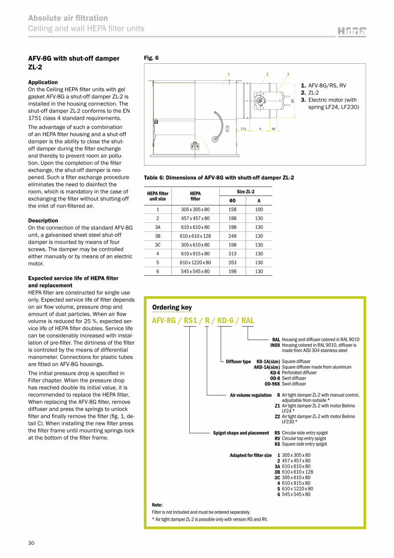
AFV-8 with shut-off damper ZL-2
ApplicationOn the ceiling HEPA filter unit AFV-8 a shut-off damper ZL-2 is installed in the housing connection. The shut-off damper ZL-2 conforms to the EN 1751 class 4 standard requirements.The advantage of such a combination of an HEPA filter housing and a shut-off damper is the ability to close the shut-off damper during the filter exchange and thereby to prevent room air pollu-tion. Upon the completion of the filter exchange, the shut-off damper is reo-pened. Such a filter exchange procedure eliminates the need to disinfect the room, which is mandatory in the case of exchanging the filter without shutting-off the inlet of non-filtered air.
DescriptionOn the connection of the standard ceiling HEPA filter unit AFV-8, a galvanised sheet steel shut-off damper is mounted by means of four screws. The damper may be controlled either manually or by means of an electric motor.
Table 5: Dimensions of AFV-8 with shut-off damper ZL-2
AFV-8 ZL-2
Size HEPA filter фD size A
1 305 x 305 x 150 148 150 100
2A 457 x 457 x 78 198 200 130
2B 457 x 457 x 150 198 200 130
3 610 x 610 x 78 198 200 130
4 610 x 610 x 150 298 300 130
5 610 x 610 x 292 348 350 130
Table 4: Filter and front plate combinations
Filter unit size HEPA filter A*
Diffuser size**
KD-1 KD-6 OD-8K OD-9K
1 305 x 305 x 150 355 x 355 1,2,3 √ - 400
2A 457 x 457 x 78 507 x 507 3,4 √ 500/16 500
2B 457 x 457 x 150 507 x 507 3,4 √ 500/16 500
3 610 x 610 x 78 660 x 660 5,6,7,8 √ 600/24, 625/54 600
4 610 x 610 x 150 660 x 660 7,8 √ 600/24, 625/54 600
5 610 x 610 x 292 660 x 660 7,8 √ 600/24, 625/54 600
* Outer dimension of diffuser front plate.
Fig. 5
1. AFV-8/RS, RV2. ZL-23. Electric motor
(with spring LF24, LF230)
77.5 A
A
40
1 2 3
16
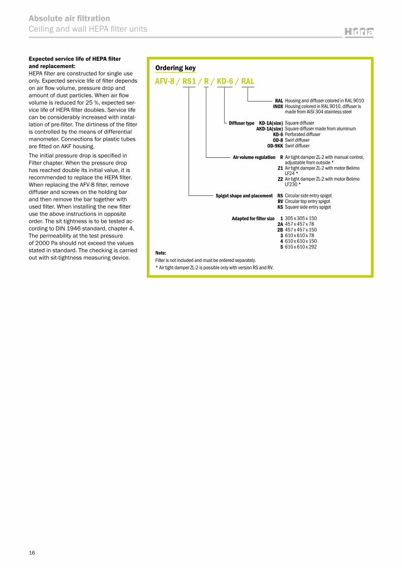
Expected service life of HEPA filter and replacement: HEPA filter are constructed for single use only. Expected service life of filter depends on air flow volume, pressure drop and amount of dust particles. When air flow volume is reduced for 25 %, expected ser-vice life of HEPA filter doubles. Service life can be considerably increased with instal-lation of pre-filter. The dirtiness of the filter is controlled by the means of differential manometer. Connections for plastic tubes are fitted on AKF housing.The initial pressure drop is specified in Filter chapter. When the pressure drop has reached double its initial value, it is recommended to replace the HEPA filter. When replacing the AFV-8 filter, remove diffuser and screws on the holding bar and then remove the bar together with used filter. When installing the new filter use the above instructions in opposite order. The sit tightness is to be tested ac-cording to DIN 1946 standard, chapter 4. The permeability at the test pressure of 2000 Pa should not exceed the values stated in standard. The checking is carried out with sit-tightness measuring device.
Ordering key
RAL Housing and diffuser colored in RAL 9010INOX Housing colored in RAL 9010, diffuser is
made from AISI 304 stainless steel
Diffuser type KD-1A(size) Square diffuser AKD-1A(size) Square diffuser made from aluminum
KD-6 Perforated diffuserOD-8 Swirl diffuser
OD-9KK Swirl diffuser
Air volume regulation R Air tight damper ZL-2 with manual control, adjustable from outside *
Z1 Air tight damper ZL-2 with motor Belimo LF24 *
Z2 Air tight damper ZL-2 with motor Belimo LF230 *
Spigot shape and placement RS Circular side entry spigotRV Circular top entry spigotKS Square side entry spigot
Adapted for filter size 1 305 x 305 x 1502A 457 x 457 x 782B 457 x 457 x 150
3 610 x 610 x 784 610 x 610 x 1505 610 x 610 x 292
AFV-8 / RS1 / R / KD-6 / RAL
Note:Filter is not included and must be ordered separately.* Air tight damper ZL-2 is possible only with version RS and RV.
Absolute air filtrationCeiling and wall HEPA filter units
B2
B1B0
b
a
A2 ~80
A1A0
A
1
3
2
4
7
A
8
9
5
6
6
ф9
фd
H F
B2
A
A
B1
H3H1
H0
B0
A2фd
A1
H F
A0
16
8
9
6
3
2
4
7
ф9
~65
b
a
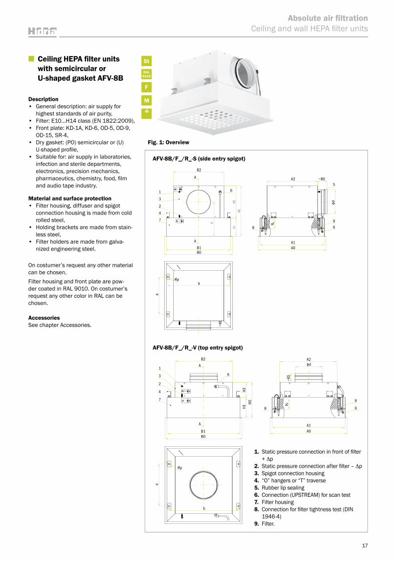
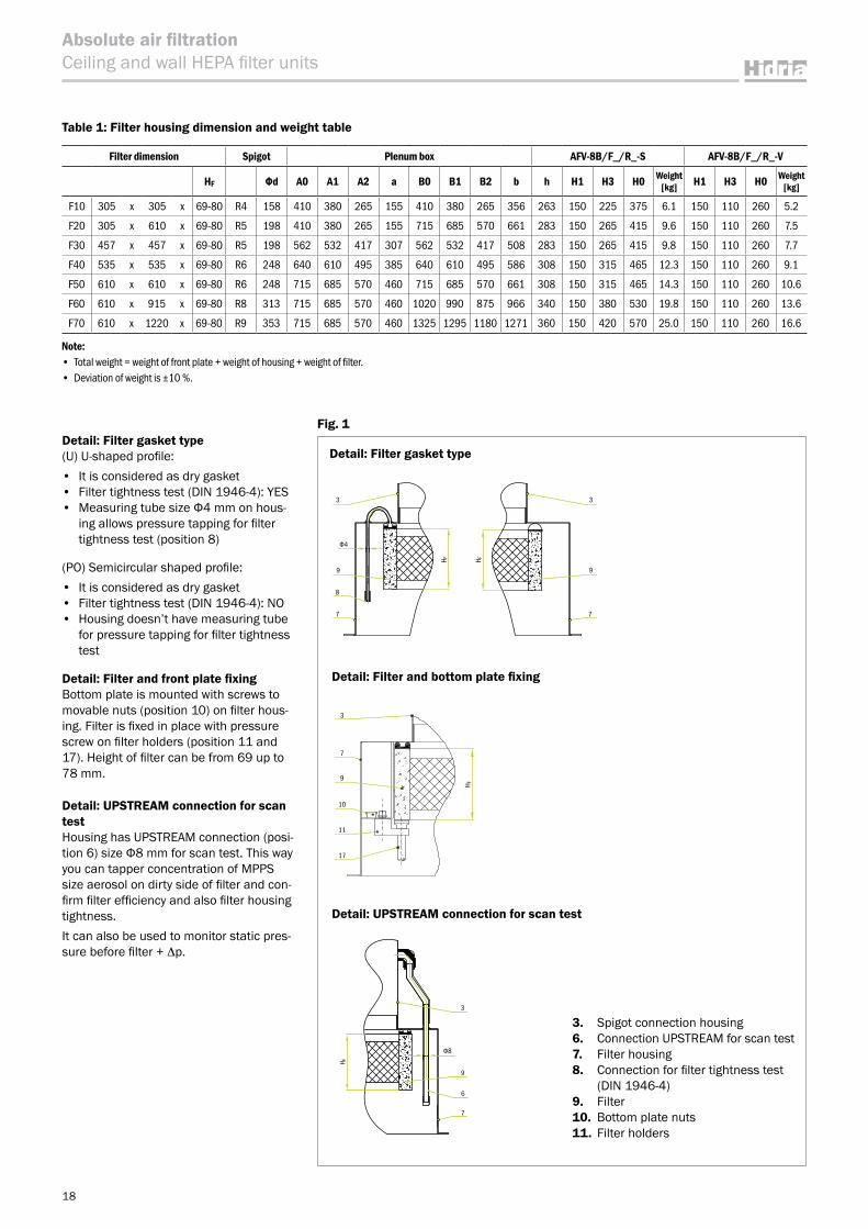
■ Ceiling HEPA filter units with semicircular or U-shaped gasket AFV-8B
Description• General description: air supply for
highest standards of air purity,• Filter: E10…H14 class (EN 1822:2009),• Front plate: KD-1A, KD-6, OD-5, OD-9,
OD-15, SR-4,• Dry gasket: (PO) semicircular or (U)
U-shaped profile,• Suitable for: air supply in laboratories,
infection and sterile departments, electronics, precision mechanics, pharmaceutics, chemistry, food, film and audio tape industry.
Material and surface protection• Filter housing, diffuser and spigot
connection housing is made from cold rolled steel,
• Holding brackets are made from stain-less steel,
• Filter holders are made from galva-nized engineering steel.
On costumer’s request any other material can be chosen.Filter housing and front plate are pow-der coated in RAL 9010. On costumer’s request any other color in RAL can be chosen.
AccessoriesSee chapter Accessories.
AFV-8B/F_/R_-S (side entry spigot)
AFV-8B/F_/R_-V (top entry spigot)
1. Static pressure connection in front of filter + Δp
2. Static pressure connection after filter – Δp3. Spigot connection housing4. “O” hangers or “T” traverse5. Rubber lip sealing6. Connection (UPSTREAM) for scan test7. Filter housing8. Connection for filter tightness test (DIN
1946-4)9. Filter.
17
St
RAL9010
F
M
Absolute air filtrationCeiling and wall HEPA filter units
Fig. 1: Overview
Detail: Filter gasket type
18
Absolute air filtrationCeiling and wall HEPA filter units
Detail: Filter gasket type(U) U-shaped profile: • It is considered as dry gasket• Filter tightness test (DIN 1946-4): YES• Measuring tube size Ф4 mm on hous-
ing allows pressure tapping for filter tightness test (position 8)
(PO) Semicircular shaped profile: • It is considered as dry gasket• Filter tightness test (DIN 1946-4): NO• Housing doesn’t have measuring tube
for pressure tapping for filter tightness test
Detail: Filter and front plate fixingBottom plate is mounted with screws to movable nuts (position 10) on filter hous-ing. Filter is fixed in place with pressure screw on filter holders (position 11 and 17). Height of filter can be from 69 up to 78 mm.
Detail: UPSTREAM connection for scan testHousing has UPSTREAM connection (posi-tion 6) size Ф8 mm for scan test. This way you can tapper concentration of MPPS size aerosol on dirty side of filter and con-firm filter efficiency and also filter housing tightness.It can also be used to monitor static pres-sure before filter + Δp.
Detail: Filter and bottom plate fixing
Table 1: Filter housing dimension and weight table
Filter dimension Spigot Plenum box AFV-8B/F_/R_-S AFV-8B/F_/R_-V
HF Фd A0 A1 A2 a B0 B1 B2 b h H1 H3 H0 Weight [kg] H1 H3 H0 Weight
[kg]
F10 305 x 305 x 69-80 R4 158 410 380 265 155 410 380 265 356 263 150 225 375 6.1 150 110 260 5.2
F20 305 x 610 x 69-80 R5 198 410 380 265 155 715 685 570 661 283 150 265 415 9.6 150 110 260 7.5
F30 457 x 457 x 69-80 R5 198 562 532 417 307 562 532 417 508 283 150 265 415 9.8 150 110 260 7.7
F40 535 x 535 x 69-80 R6 248 640 610 495 385 640 610 495 586 308 150 315 465 12.3 150 110 260 9.1
F50 610 x 610 x 69-80 R6 248 715 685 570 460 715 685 570 661 308 150 315 465 14.3 150 110 260 10.6
F60 610 x 915 x 69-80 R8 313 715 685 570 460 1020 990 875 966 340 150 380 530 19.8 150 110 260 13.6
F70 610 x 1220 x 69-80 R9 353 715 685 570 460 1325 1295 1180 1271 360 150 420 570 25.0 150 110 260 16.6
Note: • Total weight = weight of front plate + weight of housing + weight of filter.• Deviation of weight is ±10 %.
3
Φ4
9 9
3
8
7 7
H F H F
3
7
9
10
11
17
H F
Detail: UPSTREAM connection for scan test
3. Spigot connection housing6. Connection UPSTREAM for scan test7. Filter housing8. Connection for filter tightness test
(DIN 1946-4)9. Filter10. Bottom plate nuts11. Filter holders
Φ8
9
6
7
3
H F
Fig. 1
Detail: Side entry spigot with air volume regulator
Table 2: Additional weight for air volume regulator
Spigot
ФdWeight
[kg]
R4 158 0.3
R5 198 0.4
R6 248 0.5
19
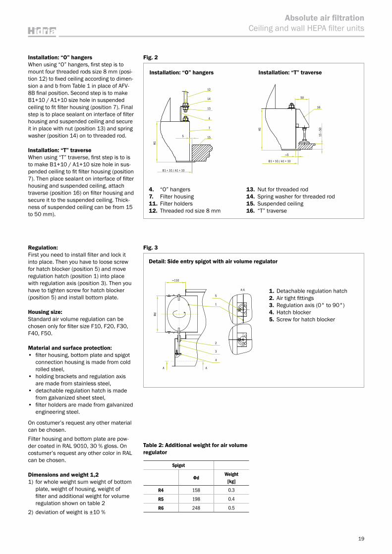
Regulation:First you need to install filter and lock it into place. Then you have to loose screw for hatch blocker (position 5) and move regulation hatch (position 1) into place with regulation axis (position 3). Then you have to tighten screw for hatch blocker (position 5) and install bottom plate.
Housing size:Standard air volume regulation can be chosen only for filter size F10, F20, F30, F40, F50.
Material and surface protection:• filter housing, bottom plate and spigot
connection housing is made from cold rolled steel,
• holding brackets and regulation axis are made from stainless steel,
• detachable regulation hatch is made from galvanized sheet steel,
• filter holders are made from galvanized engineering steel.
On costumer’s request any other material can be chosen.Filter housing and bottom plate are pow-der coated in RAL 9010, 30 % gloss. On costumer’s request any other color in RAL can be chosen.
Dimensions and weight 1,21) for whole weight sum weight of bottom
plate, weight of housing, weight of filter and additional weight for volume regulation shown on table 2
2) deviation of weight is ±10 %
Absolute air filtrationCeiling and wall HEPA filter units
1. Detachable regulation hatch2. Air tight fittings3. Regulation axis (0° to 90°)4. Hatch blocker5. Screw for hatch blocker
Installation: “O” hangersWhen using “O” hangers, first step is to mount four threaded rods size 8 mm (posi-tion 12) to fixed ceiling according to dimen-sion a and b from Table 1 in place of AFV-8B final position. Second step is to make B1+10 / A1+10 size hole in suspended ceiling to fit filter housing (position 7). Final step is to place sealant on interface of filter housing and suspended ceiling and secure it in place with nut (position 13) and spring washer (position 14) on to threaded rod.
Installation: “T” traverseWhen using “T” traverse, first step is to is to make B1+10 / A1+10 size hole in sus-pended ceiling to fit filter housing (position 7). Then place sealant on interface of filter housing and suspended ceiling, attach traverse (position 16) on filter housing and secure it to the suspended ceiling. Thick-ness of suspended ceiling can be from 15 to 50 mm).
Installation: “T” traverseInstallation: “O” hangers
4. “O” hangers7. Filter housing11. Filter holders12. Threaded rod size 8 mm
13. Nut for threaded rod 14. Spring washer for threaded rod15. Suspended ceiling16. “T” traverse
Fig. 3
12
14
13
15
B1 + 10 / A1 + 10
4
7
H1
16
B1 + 10 / A1 + 10
50
~5
H1
15 –:
50
Fig. 2
~110
5
1
2
3
4
AA
A:A
Φd
5
1330
720
415
415
415
720
567
567
645
645
720
720
1025
720
20
Absolute air filtrationCeiling and wall HEPA filter units
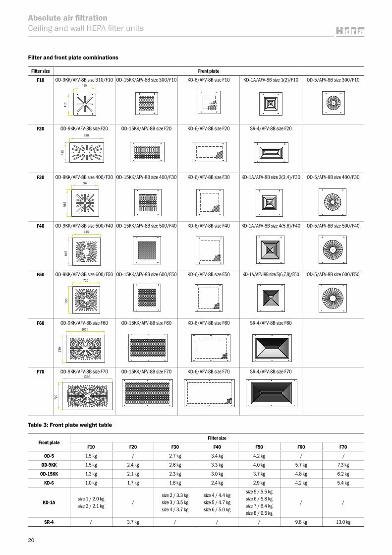
Filter size Front plate
F10 OD-9KK/AFV-8B size 310/F10 OD-15KK/AFV-8B size 300/F10 KD-6/AFV-8B size F10 KD-1A/AFV-8B size 1(2)/F10 OD-5/AFV-8B size 300/F10
F20 OD-9KK/AFV-8B size F20 OD-15KK/AFV-8B size F20 KD-6/AFV-8B size F20 SR-4/AFV-8B size F20
F30 OD-9KK/AFV-8B size 400/F30 OD-15KK/AFV-8B size 400/F30 KD-6/AFV-8B size F30 KD-1A/AFV-8B size 2(3,4)/F30 OD-5/AFV-8B size 400/F30
F40 OD-9KK/AFV-8B size 500/F40 OD-15KK/AFV-8B size 500/F40 KD-6/AFV-8B size F40 KD-1A/AFV-8B size 4(5,6)/F40 OD-5/AFV-8B size 500/F40
F50 OD-9KK/AFV-8B size 600/F50 OD-15KK/AFV-8B size 600/F50 KD-6/AFV-8B size F50 KD-1A/AFV-8B size 5(6,7,8)/F50 OD-5/AFV-8B size 600/F50
F60 OD-9KK/AFV-8B size F60 OD-15KK/AFV-8B size F60 KD-6/AFV-8B size F60 SR-4/AFV-8B size F60
F70 OD-9KK/AFV-8B size F70 OD-15KK/AFV-8B size F70 KD-6/AFV-8B size F70 SR-4/AFV-8B size F70
Table 3: Front plate weight table
Front plateFilter size
F10 F20 F30 F40 F50 F60 F70
OD-5 1.5 kg / 2.7 kg 3.4 kg 4.2 kg / /
OD-9KK 1.5 kg 2.4 kg 2.6 kg 3.3 kg 4.0 kg 5.7 kg 7.3 kg
OD-15KK 1.3 kg 2.1 kg 2.3 kg 3.0 kg 3.7 kg 4.8 kg 6.2 kg
KD-6 1.0 kg 1.7 kg 1.8 kg 2.4 kg 2.9 kg 4.2 kg 5.4 kg
KD-1Asize 1 / 2.0 kgsize 2 / 2.1 kg
/size 2 / 3.3 kgsize 3 / 3.5 kgsize 4 / 3.7 kg
size 4 / 4.4 kgsize 5 / 4.7 kgsize 6 / 5.0 kg
size 5 / 5.5 kgsize 6 / 5.8 kgsize 7 / 6.4 kgsize 8 / 6.5 kg
/ /
SR-4 / 3.7 kg / / / 9.8 kg 13.0 kg
Filter and front plate combinations
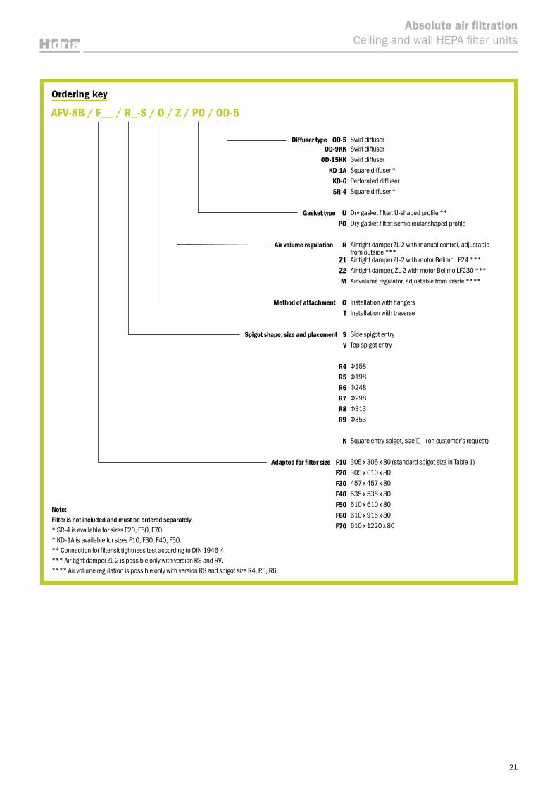
Ordering key
Diffuser type OD-5 Swirl diffuserOD-9KK Swirl diffuser
OD-15KK Swirl diffuserKD-1A Square diffuser *
KD-6 Perforated diffuserSR-4 Square diffuser *
Gasket type U Dry gasket filter: U-shaped profile **PO Dry gasket filter: semicircular shaped profile
Air volume regulation R Air tight damper ZL-2 with manual control, adjustable from outside ***
Z1 Air tight damper ZL-2 with motor Belimo LF24 ***Z2 Air tight damper, ZL-2 with motor Belimo LF230 ***M Air volume regulator, adjustable from inside ****
Method of attachment O Installation with hangersT Installation with traverse
Spigot shape, size and placement S Side spigot entryV Top spigot entry
R4 Ф158R5 Ф198R6 Ф248R7 Ф298R8 Ф313R9 Ф353
K Square entry spigot, size □_ (on customer’s request)
Adapted for filter size F10 305 x 305 x 80 (standard spigot size in Table 1) F20 305 x 610 x 80 F30 457 x 457 x 80 F40 535 x 535 x 80 F50 610 x 610 x 80 F60 610 x 915 x 80 F70 610 x 1220 x 80
AFV-8B / F__ / R_-S / O / Z / PO / OD-5
Note:Filter is not included and must be ordered separately.* SR-4 is available for sizes F20, F60, F70.* KD-1A is available for sizes F10, F30, F40, F50.** Connection for filter sit tightness test according to DIN 1946-4.*** Air tight damper ZL-2 is possible only with version RS and RV.**** Air volume regulation is possible only with version RS and spigot size R4, R5, R6.
21
Absolute air filtrationCeiling and wall HEPA filter units
St
RAL9010
F
M
22
Absolute air filtrationCeiling and wall HEPA filter units
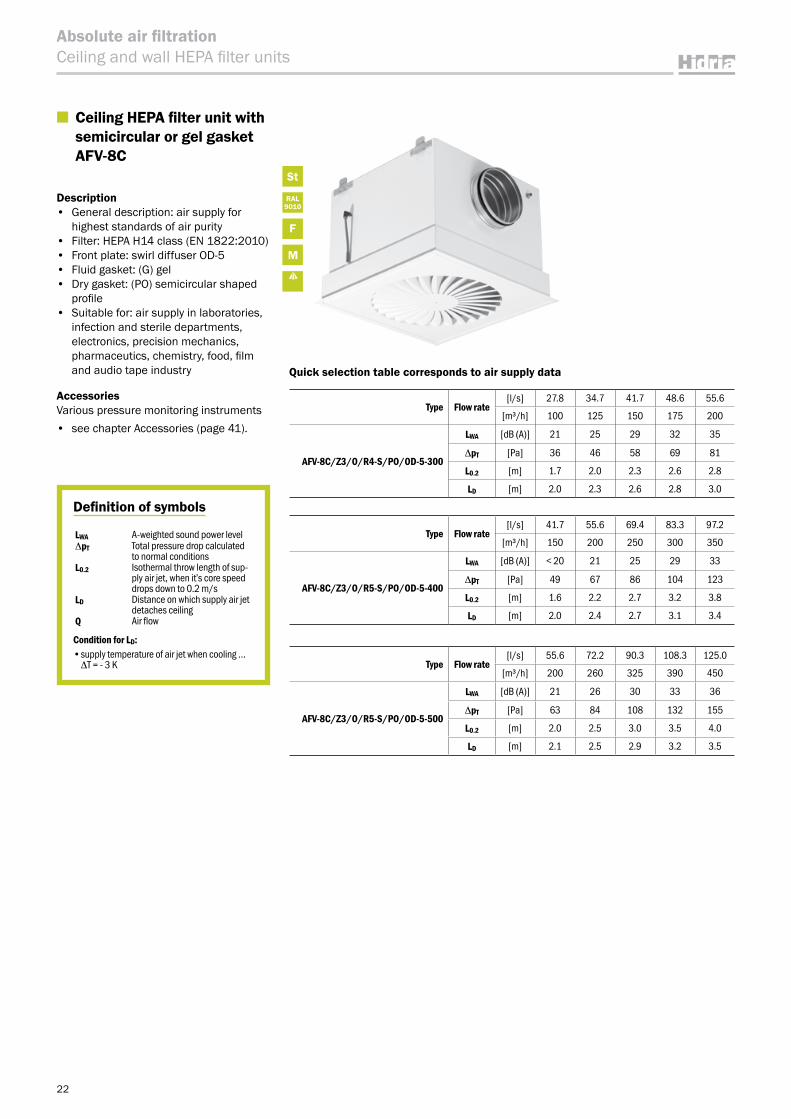
■ Ceiling HEPA filter unit with semicircular or gel gasket AFV-8C
Description• General description: air supply for
highest standards of air purity• Filter: HEPA H14 class (EN 1822:2010)• Front plate: swirl diffuser OD-5• Fluid gasket: (G) gel• Dry gasket: (PO) semicircular shaped
profile• Suitable for: air supply in laboratories,
infection and sterile departments, electronics, precision mechanics, pharmaceutics, chemistry, food, film and audio tape industry
AccessoriesVarious pressure monitoring instruments• see chapter Accessories (page 41).
Definition of symbols
LWA A-weighted sound power levelΔpT Total pressure drop calculated
to normal conditionsL0.2 Isothermal throw length of sup-
ply air jet, when itʼs core speed drops down to 0.2 m/s
LD Distance on which supply air jet detaches ceiling
Q Air flow
Condition for LD:•supplytemperatureofairjetwhencooling…ΔT = - 3 K
Quick selection table corresponds to air supply data
Type Flow rate[l/s] 27.8 34.7 41.7 48.6 55.6
[m³/h] 100 125 150 175 200
AFV-8C/Z3/O/R4-S/PO/OD-5-300
LWA [dB (A)] 21 25 29 32 35
ΔpT [Pa] 36 46 58 69 81
L0.2 [m] 1.7 2.0 2.3 2.6 2.8
LD [m] 2.0 2.3 2.6 2.8 3.0
Type Flow rate[l/s] 41.7 55.6 69.4 83.3 97.2
[m³/h] 150 200 250 300 350
AFV-8C/Z3/O/R5-S/PO/OD-5-400
LWA [dB (A)] < 20 21 25 29 33
ΔpT [Pa] 49 67 86 104 123
L0.2 [m] 1.6 2.2 2.7 3.2 3.8
LD [m] 2.0 2.4 2.7 3.1 3.4
Type Flow rate[l/s] 55.6 72.2 90.3 108.3 125.0
[m³/h] 200 260 325 390 450
AFV-8C/Z3/O/R5-S/PO/OD-5-500
LWA [dB (A)] 21 26 30 33 36
ΔpT [Pa] 63 84 108 132 155
L0.2 [m] 2.0 2.5 3.0 3.5 4.0
LD [m] 2.1 2.5 2.9 3.2 3.5
23
Absolute air filtrationCeiling and wall HEPA filter units
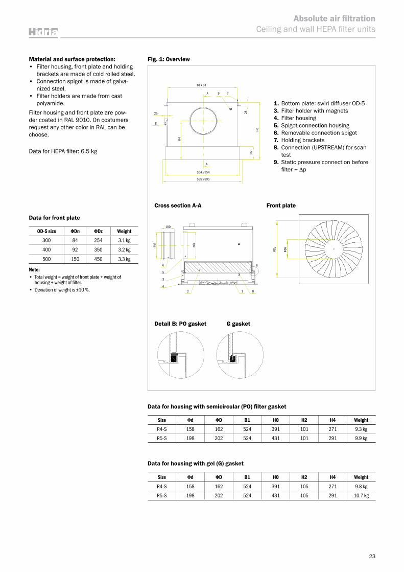
Material and surface protection:• Filter housing, front plate and holding
brackets are made of cold rolled steel,• Connection spigot is made of galva-
nized steel,• Filter holders are made from cast
polyamide.Filter housing and front plate are pow-der coated in RAL 9010. On costumers request any other color in RAL can be choose.
Data for HEPA filter: 6.5 kg
Data for housing with semicircular (PO) filter gasket
Size Фd ФD B1 H0 H2 H4 Weight
R4-S 158 162 524 391 101 271 9.3 kg
R5-S 198 202 524 431 101 291 9.9 kg
Data for housing with gel (G) gasket
Size Фd ФD B1 H0 H2 H4 Weight
R4-S 158 162 524 391 105 271 9.8 kg
R5-S 198 202 524 431 105 291 10.7 kg
Cross section A-A Front plate
1. Bottom plate: swirl diffuser OD-53. Filter holder with magnets4. Filter housing5. Spigot connection housing6. Removable connection spigot7. Holding brackets8. Connection (UPSTREAM) for scan
test 9. Static pressure connection before
filter + Δp
Data for front plate
OD-5 size ФDn ФDz Weight
300 84 254 3.1 kg
400 92 350 3.2 kg
500 150 450 3.3 kg
Note:• Total weight = weight of front plate + weight of
housing + weight of filter.• Deviation of weight is ±10 %.
Detail B: PO gasket G gasket
ФDФd
100
6
5
3
24
1 8
8
B1 x B1
25
H4
H2
H0
28
8
A 9 7
A
554 x 554
595 x 595
ФDz
ФDn
Fig. 1: Overview
24
Absolute air filtrationCeiling and wall HEPA filter units
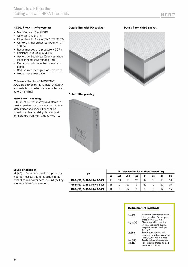
HEPA filter – information• Manufacturer: CamfilFARR• Size: 508 x 508 x 86• Filter class: H14 class (EN 1822:2009)• Air flow / initial pressure: 700 m³/h /
168 Pa• Recommended end pressure: 450 Pa• Efficiency: ≥ 99,995 % MPPS• Gasket: gel liquid seal (G) or semicircu-
lar expanded polyurethane (PO)• Frame: extruded anodized aluminum
profile• Grid: painted steel grids on both sides• Media: glass fiber paper
With every filter, list of IMPORTANT ADVICES is given by manufacturer. Safety and installation instructions must be read before handling!
HEPA filter – handling:Filter must be transported and stored in vertical position as it is shown on picture (detail: filter packing). Filter shall be stored in a clean and dry place with air temperature from +5 °C up to +40 °C.
Sound attenuationΔL [dB] … Sound attenuation represents insertion losses; this is reduction in the level of sound power because unit (ceiling filter unit AFV-8C) is inserted.
Detail: filter with PO gasket Detail: filter with G gasket
Detail: filter packing
Definition of symbols
L0.2 [m] Isothermal throw length of sup-ply air jet, when itʼs core speed drops down to 0.2 m/s
LD, -3K [m] Distance on which supply air jet detaches ceiling, supply temperature when cooling of ΔT= - 3 K
ΔL [dB] Sound attenuation, which represents insertion losses; this means reduction in the level
LWA [dB] A-weighted sound power levelΔpT [Pa] Total pressure drop calculated
to normal conditions
TypeΔL … sound attenuation respective to octave [Hz]
63 125 250 500 1k 2k 4k 8k
AFV-8C/Z3/O/R4-S/PO/OD-5-300 19 13 15 12 12 11 15 16
AFV-8C/Z3/O/R5-S/PO/OD-5-400 11 9 12 9 10 9 12 15
AFV-8C/Z3/O/R5-S/PO/OD-5-500 11 9 12 9 9 9 12 15
25
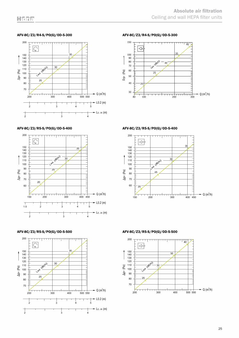
Absolute air filtrationCeiling and wall HEPA filter units
80Q (m /h) 3
100 200 300
DpT
(P
a)
30
100
150
40
50
60
70
8090
Lwa (dB(A))
25
30
35
40
20
AFV-8C/Z3/R4-S/PO(G)/OD-5-300
AFV-8C/Z3/R5-S/PO(G)/OD-5-400
AFV-8C/Z3/R5-S/PO(G)/OD-5-500
AFV-8C/Z3/R4-S/PO(G)/OD-5-300
AFV-8C/Z3/R5-S/PO(G)/OD-5-400
AFV-8C/Z3/R5-S/PO(G)/OD-5-500
Ordering key
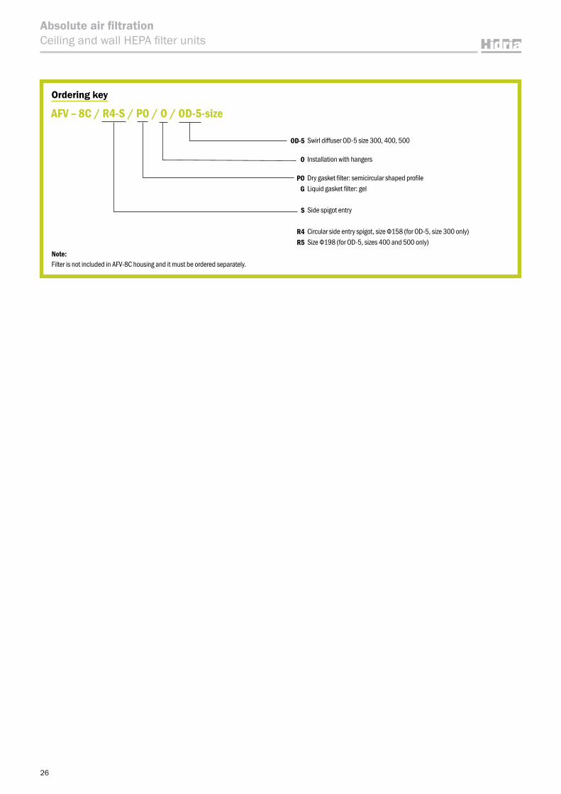
OD-5 Swirl diffuser OD-5 size 300, 400, 500
O Installation with hangers
PO Dry gasket filter: semicircular shaped profileG Liquid gasket filter: gel
S Side spigot entry
R4 Circular side entry spigot, size Ф158 (for OD-5, size 300 only)R5 Size Ф198 (for OD-5, sizes 400 and 500 only)
AFV – 8C / R4-S / PO / O / OD-5-size
Note:Filter is not included in AFV-8C housing and it must be ordered separately.
26
Absolute air filtrationCeiling and wall HEPA filter units
St
RAL9010
F
M
Fig. 1: Overview
27
Absolute air filtrationCeiling and wall HEPA filter units
For the data фD, H0, H3 for version with ZL-2 add 5 mm to the basic version.
Fig. 2
AFV-8G/RS circular side entry spigot
Table 1: Dimensions of AFV-8G/RS
HEPA filter unit size
HEPA filter
фD A B0 B1 H0 H1 H3
1 305 x 305 x 80 158 355 348 319 395 200 195
2 457 x 457 x 80 198 507 500 471 435 200 235
3A 610 x 610 x 80 198 660 653 624 435 200 235
3B 610 x 610 x 128 248 660 653 624 535 250 285
3C 305 x 610 x 80 198 355 x 660 348 x 653 319 x 624 435 200 235
4 610 x 915 x 80 313 660 x 965 653 x 958 624 x 929 550 200 350
5 610 x 1220 x 80 353 660 x 1270 653 x 1263 624 x 1234 590 200 390
6 545 x 545 x 80 198 595 588 559 435 200 235
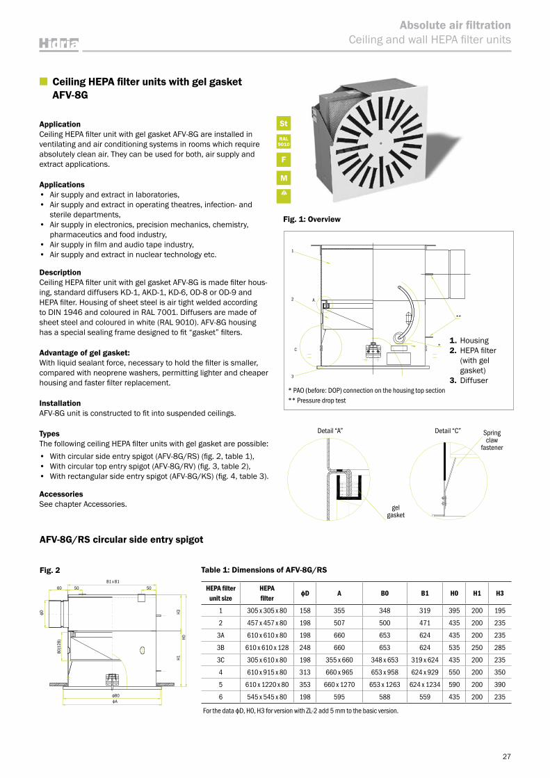
■ Ceiling HEPA filter units with gel gasket AFV-8G
ApplicationCeiling HEPA filter unit with gel gasket AFV-8G are installed in ventilating and air conditioning systems in rooms which require absolutely clean air. They can be used for both, air supply and extract applications.
Applications• Air supply and extract in laboratories, • Air supply and extract in operating theatres, infection- and
sterile departments, • Air supply in electronics, precision mechanics, chemistry,
pharmaceutics and food industry,• Air supply in film and audio tape industry, • Air supply and extract in nuclear technology etc.
DescriptionCeiling HEPA filter unit with gel gasket AFV-8G is made filter hous-ing, standard diffusers KD-1, AKD-1, KD-6, OD-8 or OD-9 and HEPA filter. Housing of sheet steel is air tight welded according to DIN 1946 and coloured in RAL 7001. Diffusers are made of sheet steel and coloured in white (RAL 9010). AFV-8G housing has a special sealing frame designed to fit “gasket” filters.
Advantage of gel gasket:With liquid sealant force, necessary to hold the filter is smaller, compared with neoprene washers, permitting lighter and cheaper housing and faster filter replacement.
InstallationAFV-8G unit is constructed to fit into suspended ceilings.
TypesThe following ceiling HEPA filter units with gel gasket are possible:• With circular side entry spigot (AFV-8G/RS) (fig. 2, table 1),• With circular top entry spigot (AFV-8G/RV) (fig. 3, table 2),• With rectangular side entry spigot (AFV-8G/KS) (fig. 4, table 3).
Accessories See chapter Accessories.
Detail “A” Detail “C” Spring claw
fastener
gel gasket
* PAO (before: DOP) connection on the housing top section** Pressure drop test
1. Housing 2. HEPA filter
(with gel gasket)
3. Diffuser
A
3
2
1
*C
**
1
2 A
C
3
80(1
28)
B1 x B1
H3H1
H0
60
фB0
фD
фA
50 50
1
2
3
A
CA
A
1
2
3
A
CA
A
28
Absolute air filtrationCeiling and wall HEPA filter units
Table 3: Dimensions of AFV-8G/KS
HEPA filter unit size
HEPA filter ФD A B0 B1 H0 H1 a1 b1 a2 b2
1 305 x 305 x 80 158 355 348 319 314 200 250 100 285 135
2 457 x 457 x 80 198 507 500 471 314 200 400 100 435 135
3A 610 x 610 x 80 198 660 653 624 314 200 500 100 535 135
3B 610 x 610 x 128 248 660 653 624 414 250 500 150 535 185
3C 305 x 610 x 80 198 355 x 660 348 x 653 319 x 624 314 200 500 100 535 135
4 610 x 915 x 80 313 660 x 965 653 x 958 624 x 929 314 200 800 100 835 135
5 610 x 1220 x 80 353 660 x 1270 653 x 1263 624 x 1234 314 200 1000 100 1035 135
6 545 x 545 x 80 198 595 588 559 314 200 400 100 435 135
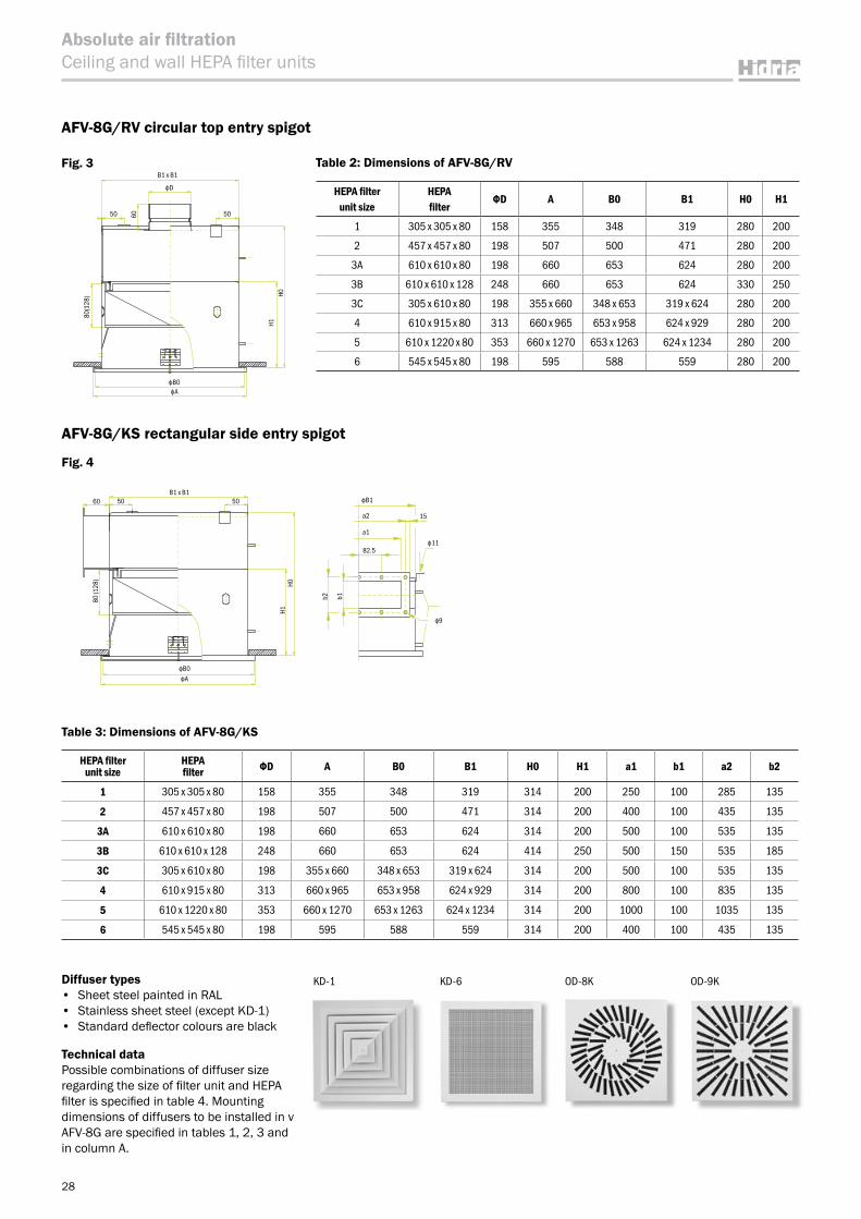
AFV-8G/RV circular top entry spigot
Fig. 3
Fig. 4
Table 2: Dimensions of AFV-8G/RV
HEPA filter unit size
HEPA filter
ФD A B0 B1 H0 H1
1 305 x 305 x 80 158 355 348 319 280 200
2 457 x 457 x 80 198 507 500 471 280 200
3A 610 x 610 x 80 198 660 653 624 280 200
3B 610 x 610 x 128 248 660 653 624 330 250
3C 305 x 610 x 80 198 355 x 660 348 x 653 319 x 624 280 200
4 610 x 915 x 80 313 660 x 965 653 x 958 624 x 929 280 200
5 610 x 1220 x 80 353 660 x 1270 653 x 1263 624 x 1234 280 200
6 545 x 545 x 80 198 595 588 559 280 200
AFV-8G/KS rectangular side entry spigot
KD-1 OD-9KOD-8KKD-6Diffuser types• Sheet steel painted in RAL• Stainless sheet steel (except KD-1)• Standard deflector colours are black
Technical dataPossible combinations of diffuser size regarding the size of filter unit and HEPA filter is specified in table 4. Mounting dimensions of diffusers to be installed in v AFV-8G are specified in tables 1, 2, 3 and in column A.
фB1
ф11
ф9
15
b2 b1
82.5
a1
a2
фB0
50 5060
80 (1
28)
H1H0
фA
B1 x B1
80(1
28)
H1
фB0
5050 60
фA
фD
B1 x B1
H0
29
Absolute air filtrationCeiling and wall HEPA filter units
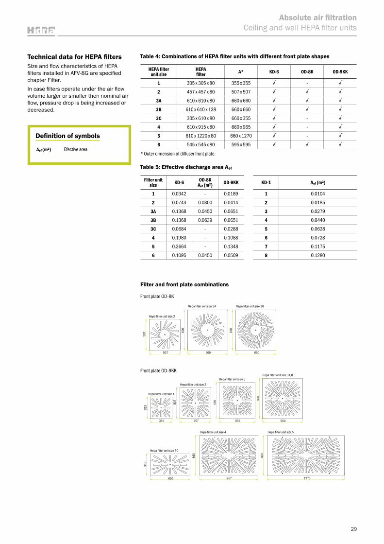
Front plate OD-8K
Table 4: Combinations of HEPA filter units with different front plate shapes
HEPA filter unit size
HEPA filter A* KD-6 OD-8K OD-9KK
1 305 x 305 x 80 355 x 355 √ - √
2 457 x 457 x 80 507 x 507 √ √ √
3A 610 x 610 x 80 660 x 660 √ √ √
3B 610 x 610 x 128 660 x 660 √ √ √
3C 305 x 610 x 80 660 x 355 √ - √
4 610 x 915 x 80 660 x 965 √ - √
5 610 x 1220 x 80 660 x 1270 √ - √
6 545 x 545 x 80 595 x 595 √ √ √
* Outer dimension of diffuser front plate.
Table 5: Effective discharge area Aef
Filter unit size KD-6 OD-8K
Aef (m²) OD-9KK
1 0.0342 - 0.0189
2 0.0743 0.0300 0.0414
3A 0.1368 0.0450 0.0651
3B 0.1368 0.0639 0.0651
3C 0.0684 - 0.0288
4 0.1980 - 0.1088
5 0.2664 - 0.1348
6 0.1095 0.0450 0.0509
KD-1 Aef (m²)
1 0.0104
2 0.0185
3 0.0279
4 0.0440
5 0.0628
6 0.0728
7 0.1175
8 0.1280
Definition of symbols
Aef (m²) Efective area
Technical data for HEPA filtersSize and flow characteristics of HEPA filters installed in AFV-8G are specified chapter Filter.In case filters operate under the air flow volume larger or smaller then nominal air flow, pressure drop is being increased or decreased.
Filter and front plate combinations
Mask OD-8
Mask OD-9
Hepa filter unit size 2
Hepa filter unit size 1
Hepa filter unit size 2
Hepa filter unit size 6Hepa filter unit size 3A,B
Hepa filter unit size 4 Hepa filter unit size 5
Hepa filter unit size 3C
507 660 660
507
507355
507
595
595
660
660 965 1270
660
660
660
355
355
660
660
Hepa filter unit size 3A Hepa filter unit size 3B
Front plate OD-9KK
600
600
660
660
507
507355
355
595
595 66
066
0
660
660
355
660
1270967
507
507
30
Absolute air filtrationCeiling and wall HEPA filter units
Ordering key
RAL Housing and diffuser colored in RAL 9010INOX Housing colored in RAL 9010, diffuser is
made from AISI 304 stainless steel
Diffuser type KD-1A(size) Square diffuser AKD-1A(size) Square diffuser made from aluminum
KD-6 Perforated diffuserOD-8 Swirl diffuser
OD-9KK Swirl diffuser
Air volume regulation R Air tight damper ZL-2 with manual control, adjustable from outside *
Z1 Air tight damper ZL-2 with motor Belimo LF24 *
Z2 Air tight damper ZL-2 with motor Belimo LF230 *
Spigot shape and placement RS Circular side entry spigotRV Circular top entry spigotKS Square side entry spigot
Adapted for filter size 1 305 x 305 x 802 457 x 457 x 80
3A 610 x 610 x 803B 610 x 610 x 1283C 305 x 610 x 80
4 610 x 915 x 805 610 x 1220 x 806 545 x 545 x 80
AFV-8G / RS1 / R / KD-6 / RAL
Note:Filter is not included and must be ordered separately.* Air tight damper ZL-2 is possible only with version RS and RV.
HEPA filter unit size
HEPA filter
Size ZL-2
ФD A
1 305 x 305 x 80 158 100
2 457 x 457 x 80 198 130
3A 610 x 610 x 80 198 130
3B 610 x 610 x 128 248 130
3C 305 x 610 x 80 198 130
4 610 x 915 x 80 313 130
5 610 x 1220 x 80 353 130
6 545 x 545 x 80 198 130
Table 6: Dimensions of AFV-8G with shutt-off damper ZL-2
AFV-8G with shut-off damper ZL-2
ApplicationOn the Ceiling HEPA filter units with gel gasket AFV-8G a shut-off damper ZL-2 is installed in the housing connection. The shut-off damper ZL-2 conforms to the EN 1751 class 4 standard requirements.The advantage of such a combination of an HEPA filter housing and a shut-off damper is the ability to close the shut-off damper during the filter exchange and thereby to prevent room air pollu-tion. Upon the completion of the filter exchange, the shut-off damper is reo-pened. Such a filter exchange procedure eliminates the need to disinfect the room, which is mandatory in the case of exchanging the filter without shutting-off the inlet of non-filtered air.
DescriptionOn the connection of the standard AFV-8G unit, a galvanised sheet steel shut-off damper is mounted by means of four screws. The damper may be controlled either manually or by means of an electric motor.
Expected service life of HEPA filter and replacement HEPA filter are constructed for single use only. Expected service life of filter depends on air flow volume, pressure drop and amount of dust particles. When air flow volume is reduced for 25 %, expected ser-vice life of HEPA filter doubles. Service life can be considerably increased with instal-lation of pre-filter. The dirtiness of the filter is controled by the means of differential manometer. Connections for plastic tubes are fitted on AFV-8G housings.The initial pressure drop is specified in Filter chapter. When the pressure drop has reached double its initial value, it is recommended to replace the HEPA filter. When replacing the AFV-8G filter, remove diffuser and press the springs to unlock filter and finally remove the filter (fig. 1, de-tail C). When installing the new filter press the filter frame until mounting springs lock at the bottom of the filter frame.
1. AFV-8G/RS, RV2. ZL-23. Electric motor (with
spring LF24, LF230)
D
A 4077.5 A
1 2 3
4077.5
фD
Fig. 6
31
Absolute air filtrationCeiling and wall HEPA filter units
Quick selection
Δp (Pa) Δp (Pa)
Front plate types Aef (m²) Q (m³/ h) G3 Q (m³/ h) G4 M5
OD-4 size 600 0.0138 100 55 50 28 58
OD-4 size 600 0.028392 200 53 100 28 55
OD-9/KK size 400 0.0248 180 55 80 22 42
OD-9/KK size 500 0.0517 400 65 190 25 60
OD-9/KR size 400 0.0248 180 55 80 22 42
OD-9/KR size 500 0.0392 280 55 140 25 55
OD-4 size 600
OD-9 KK size 500
OD-8 size 500/24
OD-9 KR size 400
OD-9 KK size 400
OD-9 KR size 500
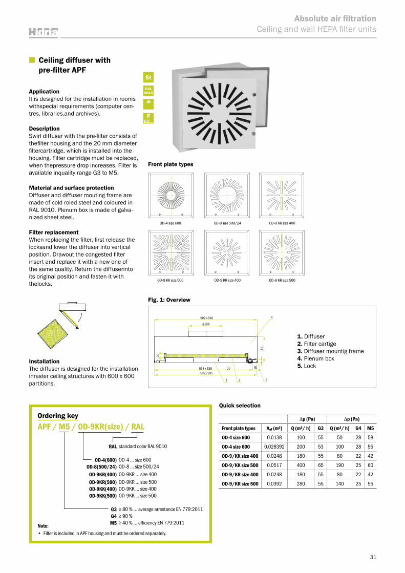
■ Ceiling diffuser with pre-filter APF
ApplicationIt is designed for the installation in rooms withspecial requirements (computer cen-tres, libraries,and archives).
DescriptionSwirl diffuser with the pre-filter consists of thefilter housing and the 20 mm diameter filtercartridge, which is installed into the housing. Filter cartridge must be replaced, when thepressure drop increases. Filter is available inquality range G3 to M5.
Material and surface protectionDiffuser and diffuser mouting frame are made of cold roled steel and coloured in RAL 9010. Plenum box is made of galva-nized sheet steel.
Filter replacementWhen replacing the filter, first release the locksand lower the diffuser into vertical position. Drawout the congested filter insert and replace it with a new one of the same quality. Return the diffuserinto its original position and fasten it with thelocks.
Front plate types
Fig. 1: Overview
InstallationThe diffuser is designed for the installation inraster ceiling structures with 600 x 600 partitions.
1. Diffuser2. Filter cartige3. Diffuser mountig frame4. Plenum box5. Lock
St
RAL9010
FEU...
Ordering key
RAL standard color RAL 9010
OD-4(600) OD-4 … size 600OD-8(500/24) OD-8 … size 500/24
OD-9KR(400) OD-9KR … size 400OD-9KR(500) OD-9KR … size 500 OD-9KK(400) OD-9KK … size 400 OD-9KK(500) OD-9KK … size 500
G3 ≥ 80 % … average arrestance EN 779:2011G4 ≥ 90 %M5 ≥ 40 % … efficiency EN 779:2011
APF / M5 / OD-9KR(size) / RAL
Note: • Filter is included in APF housing and must be ordered separately.
4592 x 592
ф198
521
27 10
20
150
538 x 538595 x 595
St
RAL9010
FEU...
32
Absolute air filtrationOperating theatre ceilings
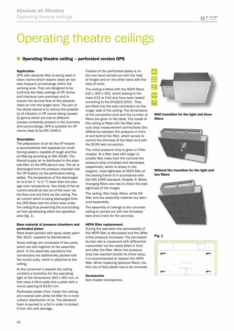
ApplicationDPS with absolute filter is being used in clean rooms which require clean air but also frequent air-exchange within the working area. They are designed to be built-into the false ceilings of OP rooms and intensive care premises and to ensure the laminar flow of the absolute clean air into the target zone. The aim of the above device is to reduce the possibil-ity of infection in OP rooms being caused by germs which are due to different causes constantly present in the premises and surroundings. DPS is suitable for OP rooms class Ib by DIN 1946-4.
Description The preparation of air for the OP theatre is accomplished with separate air condi-tioning system, capable of rough and fine air-filtering according to DIN 24185. The filtered supply air is distributed to the abso-lute filter on the DPS plenum box. The air is discharged from the pressure chamber into the OP theatre via the perforated ceiling plates. The temperature of the discharged air is to be 1° to 3 °C lower then the aver-age room temperature. Two thirds of the air current should be led out of the room via the floor and one third via the ceiling. The air current which is being discharged from the DPS flows over the entire area under the ceiling thus preventing the surrounding air from penetrating within the operation area (fig. 1).
Base material of pressure chambers and perforated platesSteel sheet painted with epoxy dusty paint RAL 9010, resistant to disinfectants.Some ceilings are composed of two parts, which are bolt together at the assembly point. In the assembly operations the connections are additionally packed with the acrylic putty, which is attached to the ceiling. At the consumer’s request the ceiling contains a transition for the operating light of the dimensions 300 x 300 mm. In that case a blind plate and a plate with a round opening of Ф150 mm.Perforated plates (from inside the ceiling) are covered with white G4 filter for a more uniform distribution of air. The delivered foam is packed in a foil in order to protect it from dirt and damage.
Fixation of the perforated plates is on the one hand carried out with the help of hinges and on the other hand with the help of locks.The ceiling is fitted with the HEPA filters 610 x 305 x 292, which belong to the class H13 or H14 and have been tested according to the EN1822:2010 . They are fitted into the side connection on the longer side of the ceiling. The dimensions of the connection duct and the number of filters are given in the table. The inside of the ceiling is fitted with the filter pres-sure drop measurement connections (the difference between the pressure in front of and behind the filter, which serves to control the dirtiness of the filter) and with the SCAN test connection.The initial pressure drop is given in Filter chapter. At a filter load with larger or smaller flow rates than the nominal the pressure drop increases and decreases respectively, which is shown in the diagram. Leak-tightness of HEPA filter at the sealing frame is in accordance with the DIN 1946 standard, Chapter 4. When changing filters one has to check the leak-tightness of the hinges.The ceiling, filter body, filters, white G4 filter and the assembly material are deliv-ered separately.The assembly of ceilings to the concrete ceiling is carried out with the threaded bars and inners for the concrete.
HEPA filter replacementDuring the operation the permeability of the HEPA filter is decreased and the differ-ential pressure increases. The permeabil-ity-loss rate is measured with differential manometer via the tubes fitted in front and after the filter. When the pressure drop has reached double its initial value, it is recommended to replace the HEPA filter. When replacing absolute filters, the first row of face plates has to be removed.
Accessories See chapter Accessories.
Fig. 1
With transition for the light and three filters
Without the transition for the light and two filters
Operating theatre ceilings ■ Operating theatre ceiling – perforated version DPS
INOX
33
Absolute air filtrationOperating theatre ceilings
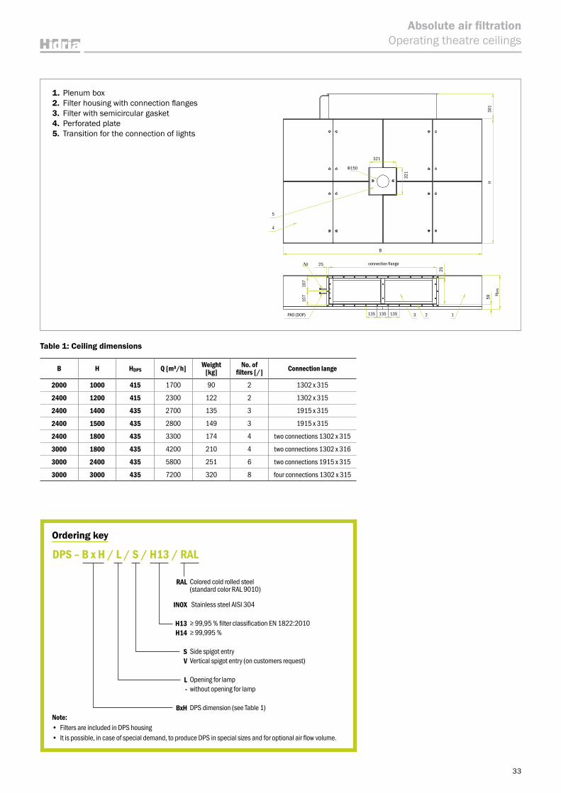
1. Plenum box2. Filter housing with connection flanges3. Filter with semicircular gasket4. Perforated plate5. Transition for the connection of lights
Table 1: Ceiling dimensions
B H HDPS Q [m³/h] Weight [kg]
No. of filters [/] Connection lange
2000 1000 415 1700 90 2 1302 x 315
2400 1200 415 2300 122 2 1302 x 315
2400 1400 435 2700 135 3 1915 x 315
2400 1500 435 2800 149 3 1915 x 315
2400 1800 435 3300 174 4 two connections 1302 x 315
3000 1800 435 4200 210 4 two connections 1302 x 316
3000 2400 435 5800 251 6 two connections 1915 x 315
3000 3000 435 7200 320 8 four connections 1302 x 315
Ordering key
RAL Colored cold rolled steel (standard color RAL 9010)
INOX Stainless steel AISI 304
H13 ≥ 99,95 % filter classification EN 1822:2010H14 ≥ 99,995 %
S Side spigot entryV Vertical spigot entry (on customers request)
L Opening for lamp- without opening for lamp
BxH DPS dimension (see Table 1)
DPS – B x H / L / S / H13 / RAL
Note: • Filters are included in DPS housing• It is possible, in case of special demand, to produce DPS in special sizes and for optional air flow volume.
Δp
2 13
B
5
4
25
135 135 135
25
59
H DPS
107
107
connection flange
321
Ф150
321
PAO (DOP)
H30
1
34
Absolute air filtrationOperating theatre ceilings
St
RAL9010
FEU...
M
INOX
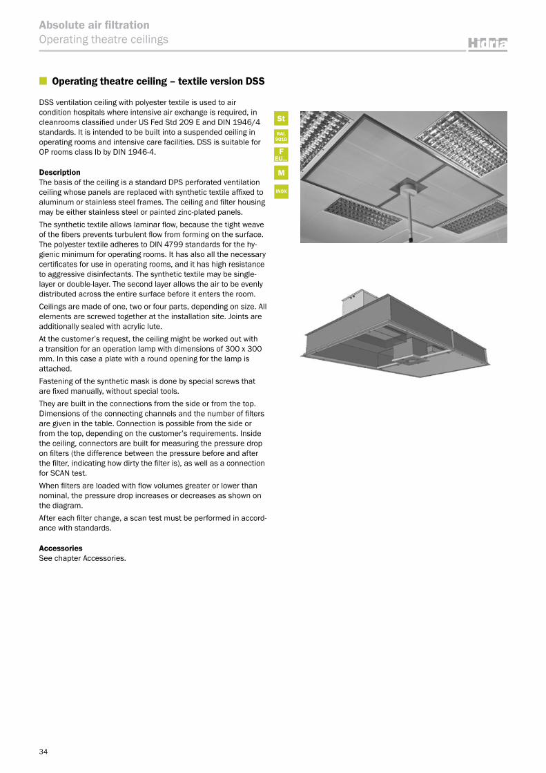
■ Operating theatre ceiling – textile version DSS
DSS ventilation ceiling with polyester textile is used to air condition hospitals where intensive air exchange is required, in cleanrooms classified under US Fed Std 209 E and DIN 1946/4 standards. It is intended to be built into a suspended ceiling in operating rooms and intensive care facilities. DSS is suitable for OP rooms class Ib by DIN 1946-4.
Description The basis of the ceiling is a standard DPS perforated ventilation ceiling whose panels are replaced with synthetic textile affixed to aluminum or stainless steel frames. The ceiling and filter housing may be either stainless steel or painted zinc-plated panels.The synthetic textile allows laminar flow, because the tight weave of the fibers prevents turbulent flow from forming on the surface. The polyester textile adheres to DIN 4799 standards for the hy-gienic minimum for operating rooms. It has also all the necessary certificates for use in operating rooms, and it has high resistance to aggressive disinfectants. The synthetic textile may be single-layer or double-layer. The second layer allows the air to be evenly distributed across the entire surface before it enters the room.Ceilings are made of one, two or four parts, depending on size. All elements are screwed together at the installation site. Joints are additionally sealed with acrylic lute.At the customer’s request, the ceiling might be worked out with a transition for an operation lamp with dimensions of 300 x 300 mm. In this case a plate with a round opening for the lamp is attached.Fastening of the synthetic mask is done by special screws that are fixed manually, without special tools.They are built in the connections from the side or from the top. Dimensions of the connecting channels and the number of filters are given in the table. Connection is possible from the side or from the top, depending on the customer’s requirements. Inside the ceiling, connectors are built for measuring the pressure drop on filters (the difference between the pressure before and after the filter, indicating how dirty the filter is), as well as a connection for SCAN test.When filters are loaded with flow volumes greater or lower than nominal, the pressure drop increases or decreases as shown on the diagram. After each filter change, a scan test must be performed in accord-ance with standards.
Accessories See chapter Accessories.
35
Absolute air filtrationOperating theatre ceilings
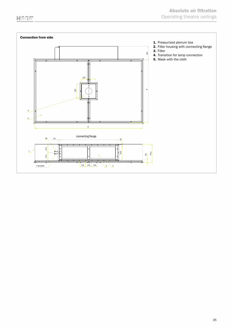
Connection from side1. Pressurized plenum box2. Filter housing with connecting flange3. Filter4. Transition for lamp connection5. Mask with the cloth
4
5
322
B
3
1
Δp 25
170
170
315
25
59 H DSS
2135135135P A0 (D0P)
H30
1
322
connecting flange
36
Absolute air filtrationOperating theatre ceilings
At two or more connections, distance between connections is a minimum of 200 mm.
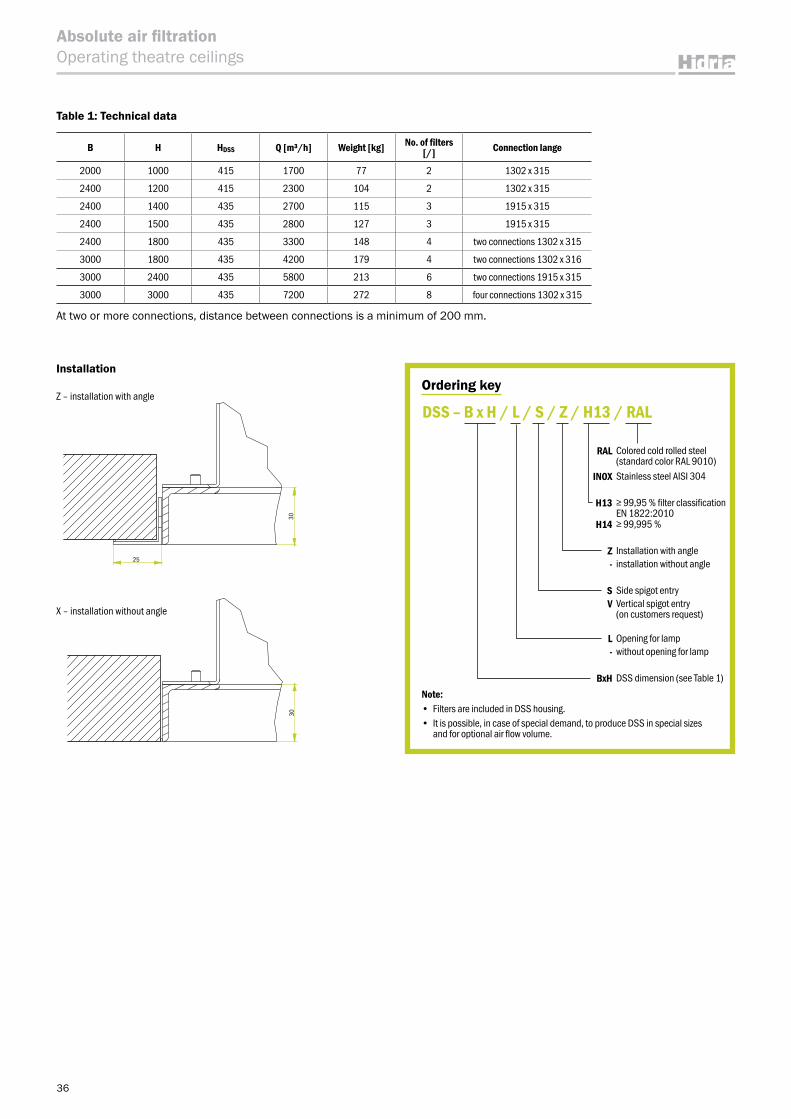
X ‒ installation without angle
Installation
Z ‒ installation with angle
Table 1: Technical data
B H HDSS Q [m³/h] Weight [kg] No. of filters [/] Connection lange
2000 1000 415 1700 77 2 1302 x 315
2400 1200 415 2300 104 2 1302 x 315
2400 1400 435 2700 115 3 1915 x 315
2400 1500 435 2800 127 3 1915 x 315
2400 1800 435 3300 148 4 two connections 1302 x 315
3000 1800 435 4200 179 4 two connections 1302 x 316
3000 2400 435 5800 213 6 two connections 1915 x 315
3000 3000 435 7200 272 8 four connections 1302 x 315
Ordering key
RAL Colored cold rolled steel (standard color RAL 9010)
INOX Stainless steel AISI 304
H13 ≥ 99,95 % filter classification EN 1822:2010
H14 ≥ 99,995 %
Z Installation with angle- installation without angle
S Side spigot entryV Vertical spigot entry
(on customers request)
L Opening for lamp- without opening for lamp
BxH DSS dimension (see Table 1)
DSS – B x H / L / S / Z / H13 / RAL
Note: • Filters are included in DSS housing.• It is possible, in case of special demand, to produce DSS in special sizes
and for optional air flow volume.
30
25
30
37
Absolute air filtrationFluff separator
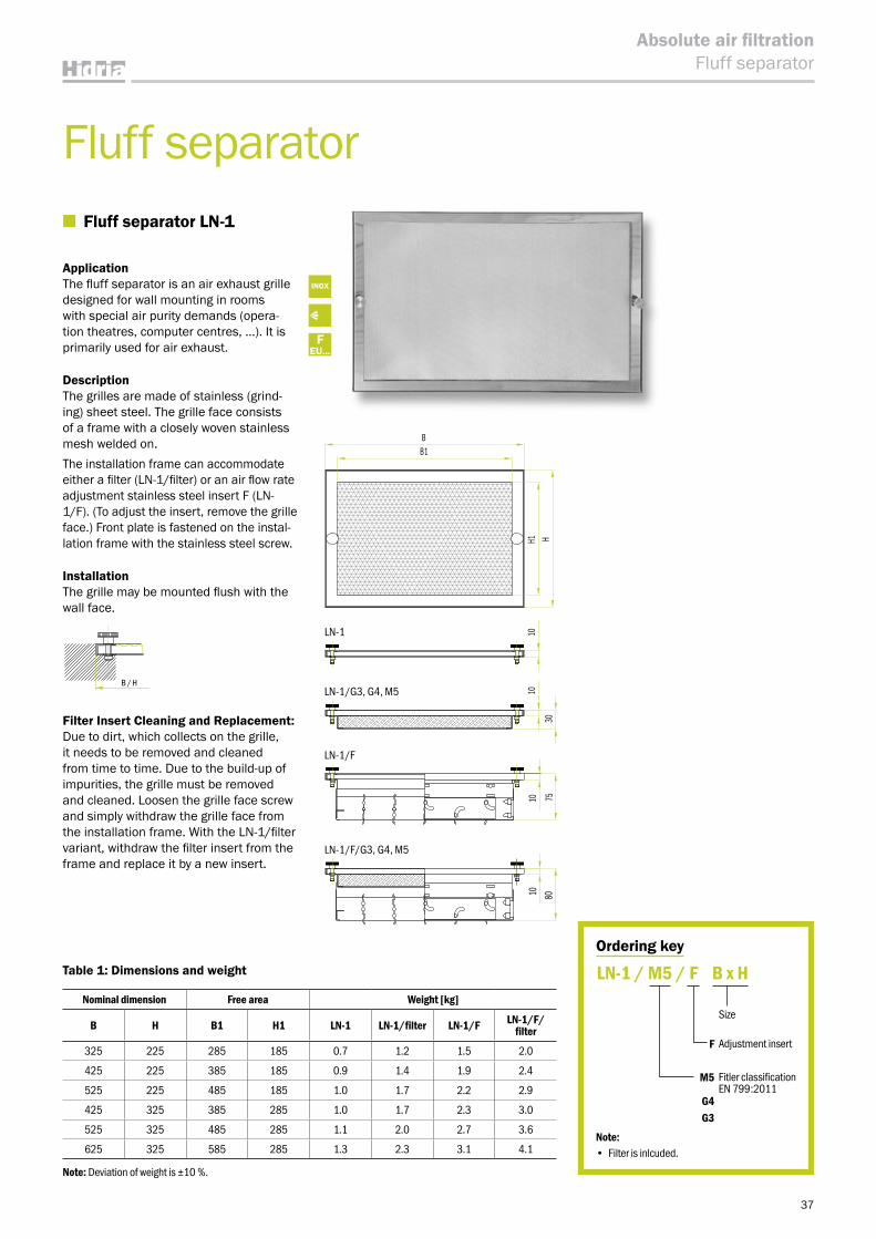
■ Fluff separator LN-1
ApplicationThe fluff separator is an air exhaust grille designed for wall mounting in rooms with special air purity demands (opera-tion theatres, computer centres, …). It is primarily used for air exhaust.
DescriptionThe grilles are made of stainless (grind-ing) sheet steel. The grille face consists of a frame with a closely woven stainless mesh welded on.The installation frame can accommodate either a filter (LN-1/filter) or an air flow rate adjustment stainless steel insert F (LN-1/F). (To adjust the insert, remove the grille face.) Front plate is fastened on the instal-lation frame with the stainless steel screw.
InstallationThe grille may be mounted flush with the wall face.
Filter Insert Cleaning and Replacement:Due to dirt, which collects on the grille, it needs to be removed and cleaned from time to time. Due to the build-up of impurities, the grille must be removed and cleaned. Loosen the grille face screw and simply withdraw the grille face from the installation frame. With the LN-1/filter variant, withdraw the filter insert from the frame and replace it by a new insert.
Table 1: Dimensions and weight
Nominal dimension Free area Weight [kg]
B H B1 H1 LN-1 LN-1/filter LN-1/F LN-1/F/filter
325 225 285 185 0.7 1.2 1.5 2.0
425 225 385 185 0.9 1.4 1.9 2.4
525 225 485 185 1.0 1.7 2.2 2.9
425 325 385 285 1.0 1.7 2.3 3.0
525 325 485 285 1.1 2.0 2.7 3.6
625 325 585 285 1.3 2.3 3.1 4.1
Ordering key
Size
F Adjustment insert
M5 Fitler classification EN 799:2011
G4G3
LN-1 / M5 / F B x H
Note: • Filter is inlcuded.
Fluff separator
INOX
FEU...
B / H
Note: Deviation of weight is ±10 %.
LN-1
LN-1/G3, G4, M5
LN-1/F
LN-1/F/G3, G4, M5
H1 H
B1B
1010
30
10 75
10 80
38
Absolute air filtrationFluff separator
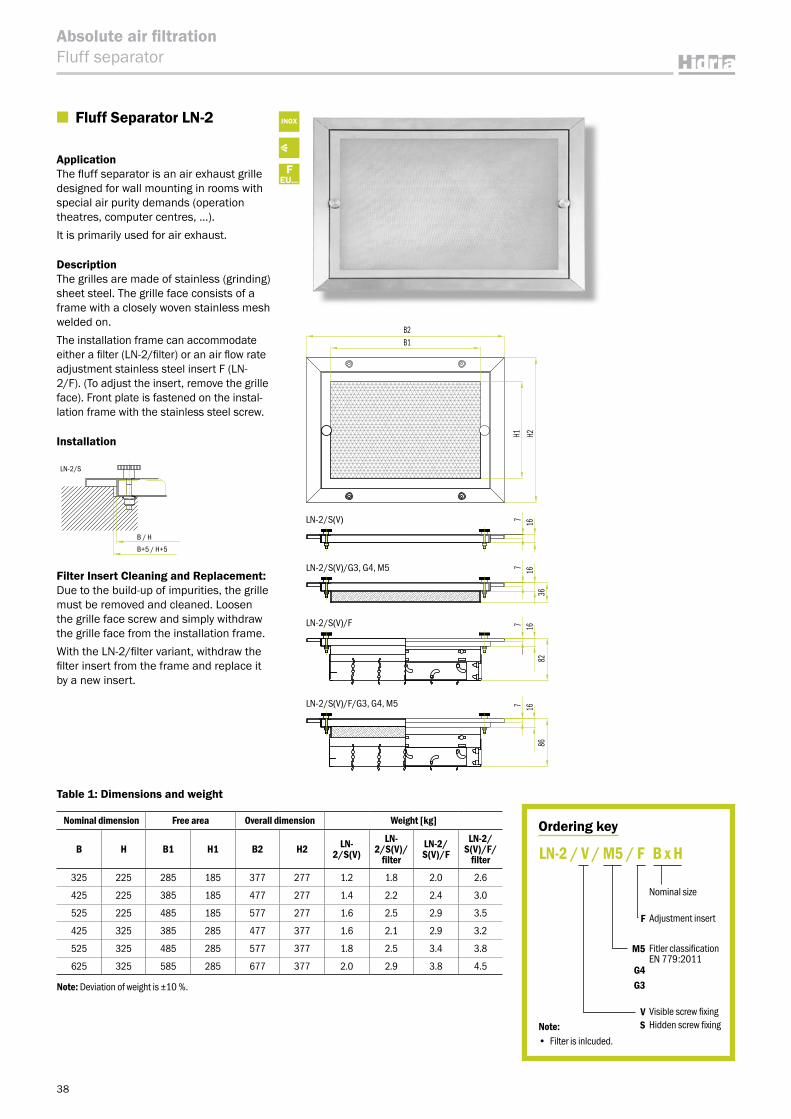
■ Fluff Separator LN-2
ApplicationThe fluff separator is an air exhaust grille designed for wall mounting in rooms with special air purity demands (operation theatres, computer centres, …).It is primarily used for air exhaust.
DescriptionThe grilles are made of stainless (grinding) sheet steel. The grille face consists of a frame with a closely woven stainless mesh welded on.The installation frame can accommodate either a filter (LN-2/filter) or an air flow rate adjustment stainless steel insert F (LN-2/F). (To adjust the insert, remove the grille face). Front plate is fastened on the instal-lation frame with the stainless steel screw.
Installation
Filter Insert Cleaning and Replacement:Due to the build-up of impurities, the grille must be removed and cleaned. Loosen the grille face screw and simply withdraw the grille face from the installation frame.With the LN-2/filter variant, withdraw the filter insert from the frame and replace it by a new insert.
Ordering key
Nominal size
F Adjustment insert
M5 Fitler classification EN 779:2011
G4G3
V Visible screw fixingS Hidden screw fixing
LN-2 / V / M5 / F B x H
Note:• Filter is inlcuded.
LN-2/S
LN-2/V
B+5 / H+5
B / H
B X H
INOX
FEU...
Table 1: Dimensions and weight
Nominal dimension Free area Overall dimension Weight [kg]
B H B1 H1 B2 H2 LN-2/S(V)
LN-2/S(V)/
filterLN-2/S(V)/F
LN-2/S(V)/F/
filter
325 225 285 185 377 277 1.2 1.8 2.0 2.6
425 225 385 185 477 277 1.4 2.2 2.4 3.0
525 225 485 185 577 277 1.6 2.5 2.9 3.5
425 325 385 285 477 377 1.6 2.1 2.9 3.2
525 325 485 285 577 377 1.8 2.5 3.4 3.8
625 325 585 285 677 377 2.0 2.9 3.8 4.5
Note: Deviation of weight is ±10 %.
H1 H2
B1B2
7 167 16
36
7 1682
7 1686
LN-2/S(V)
LN-2/S(V)/G3, G4, M5
LN-2/S(V)/F
LN-2/S(V)/F/G3, G4, M5
39
Absolute air filtrationFilter grille
33 33B1
3333
H1
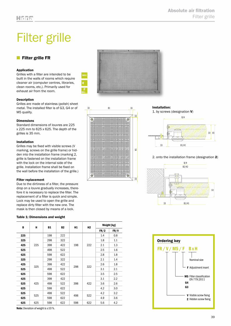
Ordering key
Nominal size
F Adjustment insert
M5 Fitler classification EN 779:2011
G4G3
V Visible screw fixing2 Hidden screw fixing
FR / V / M5 / F B x H
INOX
FEU...
Filter grille ■ Filter grille FR
ApplicationGrilles with a filter are intended to be built in the walls of rooms which require cleaner air (computer centres, libraries, clean rooms, etc,). Primarily used for exhaust air from the room.
DescriptionGrilles are made of stainless (polish) sheet metal. The installed filter is of G3, G4 or of M5 quality.
DimensionsStandard dimensions of louvres are 225 x 225 mm to 625 x 625. The depth of the grilles is 35 mm.
InstallationGrilles may be fixed with visible screws (V marking, screws on the grille frame) or hid-den into the installation frame (marking 2, grille is fastened on the installation frame with the lock on the internal side of the grille. Installation frame shall be fixed on the wall before the installation of the grille.)
Filter replacementDue to the dirtiness of a filter, the pressure drop on a louvre gradually increases, there-fore it is necessary to replace the filter. The replacement of a filter is quick and simple. Lock may be used to open the grille and replace dirty filter with the new one. The mask is then closed by means of a lock.
Installation:1. by screws (designation V)
2. onto the installation frame (designation 2)
Note: Deviation of weight is ±10 %.
B H B1 B2 H1 H2Weight [kg]
FR/2 FR/V225
225
198 222
198 222
1.4 0.8
325 298 322 1.8 1.1
425 398 422 2.1 1.3
525 498 522 2.5 1.6
625 598 622 2.8 1.8
325
325
298 322
298 322
2.1 1.4
425 398 422 2.6 1.8
525 498 522 3.1 2.1
625 598 622 3.5 2.5
425425
398 422
398 422
3.1 2.2
525 498 522 3.6 2.6
625 598 622 4.2 3.0
525525
498 522498 522
4.2 3.2
625 598 622 4.9 3.6
625 625 598 622 598 622 5.6 4.2
Table 1: Dimensions and weight
B/H
B/H
3232
35
B1/H133
B1/H1
B2/H2
33
40
Absolute air filtrationFilters
Table 1: Quick selection table according to filter class
Filter group Filter Class According to standard
Average arrestance (Am) of synthetic dust
Average efficiency (Em) of 0,4 µm
particlesMinimum efficiency of 0,4 µm particles Filter type
Coarse
G1
EN 779:2011
50 % ≤ Am < 65 % – –Bag filters (FV)
Panel filters (KA)Roll filters (FR)
G2 65 % ≤ Am < 80 % – –G3 80 % ≤ Am < 90 % – –G4 90 % ≤ Am – –
MediumM5 ‒ 40 % ≤ Em < 60 % –
Bag filters (FV)Panel filters (KA)Compact filters
(KO)
M6 – 60 % ≤ Em < 80 % –
FineF7 – 80 % ≤ Em < 90 % 35F8 – 90 % ≤ Em < 95 % 55F9 – 95 % ≤ Am 70
Table 2: Quick selection table according to filter class EPA, HEPA, ULPA
Filter group Filter class According to standard
ValueEfficiency (MPPS)
Filter type
E … EPA filtersEfficient Particulate Air Filter
E10
EN 1822–1:2010
≥ 85 %
Compact filters (KO)
EPA,HEPA,ULPA filters (H)
E11 ≥ 95 %E12 ≥ 99,5 %
H … HEPA filtersHigh Efficiency Particulate Air Filter
H13 ≥ 99,95 %H14 ≥ 99,995 %
U … ULPA filtersUltra Low Penetration Air Filter
U15 ≥ 99,9995 %U16 ≥ 99,99995 %U17 ≥ 99,999995 %
Table 3: Quick selection table according to application for carbon filters
Application type Contaminants Filter type
C1 Airports, Pharms & Food / Hydrocarbons
Carbon filters (FO)
C2 Industry / Mineral acidsC3 Industry / Ammonia, aminesC4 Industry & Waste water / (HaS), (SO2)C5 Museums & Libraries / H2S, Sox, NOx formaldehydeC6 General Purpose / General Gas RemovalC7 Nuclear industry / Radioactive dust particles
Equation 1: Quick calculation of fan energy consumption for one filter
E = qv x Δp x tηf x 1000
Filters
Definition of symbols
E [kWh]qv [m³/s]Δp [Pa]t [h]ηF [/]
energy consumed by fanair flow rate at filterfilter pressure dropoperating timefan efficiency (usually from 0.6 – 0.8)
41
Absolute air filtrationFilters
■ EPA, HEPA, ULPA filters
Liquid gasket, gel• filter version: Filter … standard• manufacturer: American Air Filter• frame material: aluminum• temperature limit: 70 °C• recommended final pressure: 500 Pa• suitable for: AFV-8G
Table 4: Filter technical data H-H14/G/ALU/AAF/F_
Filter dimensionFilter class
H14
Nominal size
WidthW
DepthD
HeightH
Pressure dropΔpS
AirflowQ
[mm] [mm] [mm] [Pa] [m³/h]F10 305 x 305 x 80 125 150F20 305 x 610 x 80 125 300F30 457 x 457 x 80 125 340F50 610 x 610 x 80 125 600F60 610 x 915 x 80 125 900F70 610 x 1220 x 80 125 1200F80 545 x 545 x 80 125 480F51 610 x 610 x 128 75 600
Liquid gasket, gel • filter version: Filter … standard• manufacturer: CamfilFARR• frame material: aluminum• temperature limit: 70 °C• recommended final pressure: 450 Pa• suitable for: AFV-8C
Table 5: Filter technical data H-H14/G/ALU/AAF/F90
Filter dimensionFilter class
H14
Nominal size
WidthW
DepthD
HeightH
Pressure dropΔpS
AirflowQ
[mm] [mm] [mm] [Pa] [m³/h]F90 508 x 508 x 86 168 700
(A ― A)A
A
W
D
H
Picture 1: Filter drawing H-H14/G/ALU/AAF/F_
(A ― A)A
A
W+20
D+20
D x W
H
Picture 2: Filter H-H14/G/ALU/CAF/F90
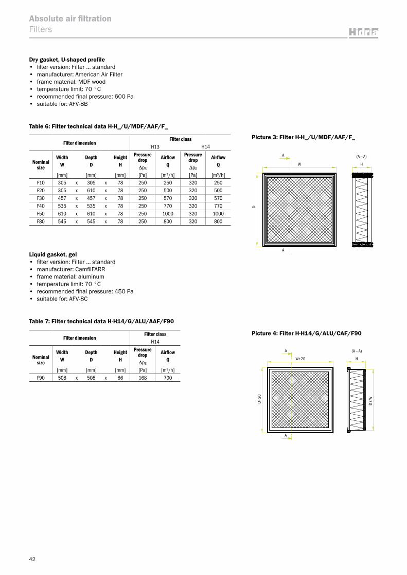
42
Absolute air filtrationFilters
Dry gasket, U-shaped profile • filter version: Filter … standard• manufacturer: American Air Filter• frame material: MDF wood • temperature limit: 70 °C• recommended final pressure: 600 Pa• suitable for: AFV-8B
Table 6: Filter technical data H-H_/U/MDF/AAF/F_
Filter dimensionFilter class
H13 H14
Nominal size
WidthW
DepthD
HeightH
Pressure dropΔpS
AirflowQ
Pressure dropΔpS
AirflowQ
[mm] [mm] [mm] [Pa] [m³/h] [Pa] [m³/h]F10 305 x 305 x 78 250 250 320 250F20 305 x 610 x 78 250 500 320 500F30 457 x 457 x 78 250 570 320 570F40 535 x 535 x 78 250 770 320 770F50 610 x 610 x 78 250 1000 320 1000F80 545 x 545 x 78 250 800 320 800
Liquid gasket, gel • filter version: Filter … standard• manufacturer: CamfilFARR• frame material: aluminum• temperature limit: 70 °C • recommended final pressure: 450 Pa• suitable for: AFV-8C
Table 7: Filter technical data H-H14/G/ALU/AAF/F90
Filter dimensionFilter class
H14
Nominal size
WidthW
DepthD
HeightH
Pressure dropΔpS
AirflowQ
[mm] [mm] [mm] [Pa] [m³/h]F90 508 x 508 x 86 168 700
(A ― A)A
A
W+20
D+20
D x W
H
Picture 4: Filter H-H14/G/ALU/CAF/F90
(A ― A)A
A
W
D
H
Picture 3: Filter H-H_/U/MDF/AAF/F_
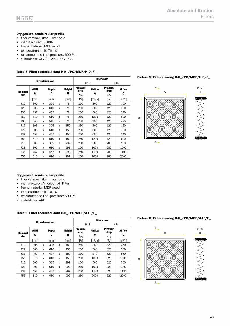
43
Absolute air filtrationFilters
Dry gasket, semicircular profile • filter version: Filter … standard• manufacturer: HIDRIA• frame material: MDF wood • temperature limit: 70 °C• recommended final pressure: 600 Pa• suitable for: AFV-8B, AKF, DPS, DSS
Table 8: Filter technical data H-H_/PO/MDF/HID/F_
Filter dimensionFilter class
H13 H14
Nominal size
WidthW
DepthD
HeightH
Pressure dropΔpS
AirflowQ
Pressure dropΔpS
AirflowQ
[mm] [mm] [mm] [Pa] [m³/h] [Pa] [m³/h]F10 305 x 305 x 78 250 300 120 150F20 305 x 610 x 78 250 600 120 300F30 457 x 457 x 78 250 680 120 340F50 610 x 610 x 78 250 1200 120 600F80 545 x 545 x 78 250 950 120 475F12 305 x 305 x 150 250 300 120 150F22 305 x 610 x 150 250 600 120 300F32 457 x 457 x 150 250 680 120 340F52 610 x 610 x 150 250 1200 120 600F13 305 x 305 x 292 250 500 280 500F23 305 x 610 x 292 250 1000 280 1000F33 457 x 457 x 292 250 1100 280 1100F53 610 x 610 x 292 250 2000 280 2000
Dry gasket, semicircular profile • filter version: Filter … standard• manufacturer: American Air Filter• frame material: MDF wood • temperature limit: 70 °C• recommended final pressure: 600 Pa• suitable for: AKF
Table 9: Filter technical data H-H_/PO/MDF/AAF/F_
Filter dimensionFilter class
H13 H14
Nominal size
WidthW
DepthD
HeightH
Pressure dropΔpS
AirflowQ
Pressure dropΔpS
AirflowQ
[mm] [mm] [mm] [Pa] [m³/h] [Pa] [m³/h]F12 305 x 305 x 150 250 250 320 250F22 305 x 610 x 150 250 500 320 500F32 457 x 457 x 150 250 570 320 570F52 610 x 610 x 150 250 1000 320 1000F13 305 x 305 x 292 250 500 320 500F23 305 x 610 x 292 250 1000 320 1000F33 457 x 457 x 292 250 1130 320 1130F53 610 x 610 x 292 250 2000 320 2000
(A ― A)A
A
W
D
H
Picture 6: Filter drawing H-H_/PO/MDF/AAF/F_
Picture 4: Filter H-H14/G/ALU/CAF/F90
(A ― A)A
A
W
D
H
Picture 5: Filter drawing H-H_/PO/MDF/HID/F_Picture 3: Filter H-H_/U/MDF/AAF/F_
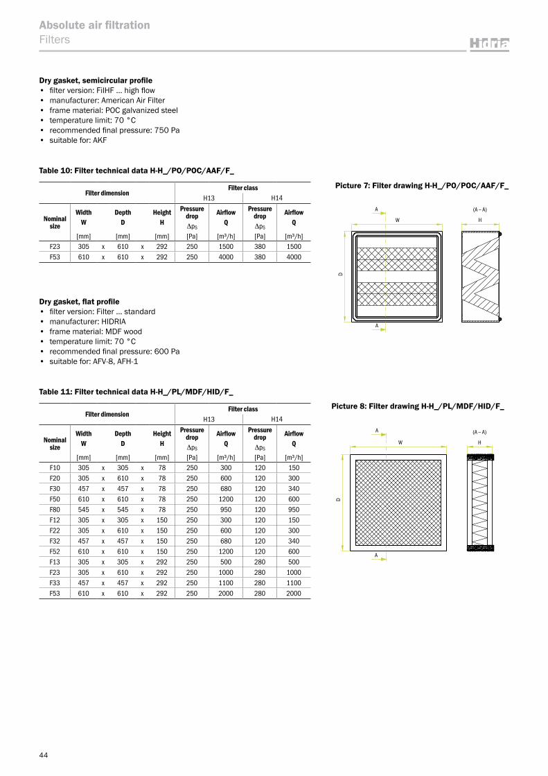
44
Absolute air filtrationFilters
Dry gasket, semicircular profile • filter version: FilHF … high flow• manufacturer: American Air Filter• frame material: POC galvanized steel • temperature limit: 70 °C• recommended final pressure: 750 Pa• suitable for: AKF
Table 10: Filter technical data H-H_/PO/POC/AAF/F_
Filter dimensionFilter class
H13 H14
Nominal size
WidthW
DepthD
HeightH
Pressure dropΔpS
AirflowQ
Pressure dropΔpS
AirflowQ
[mm] [mm] [mm] [Pa] [m³/h] [Pa] [m³/h]F23 305 x 610 x 292 250 1500 380 1500F53 610 x 610 x 292 250 4000 380 4000
Dry gasket, flat profile • filter version: Filter … standard• manufacturer: HIDRIA• frame material: MDF wood • temperature limit: 70 °C• recommended final pressure: 600 Pa• suitable for: AFV-8, AFH-1
Table 11: Filter technical data H-H_/PL/MDF/HID/F_
Filter dimensionFilter class
H13 H14
Nominal size
WidthW
DepthD
HeightH
Pressure dropΔpS
AirflowQ
Pressure dropΔpS
AirflowQ
[mm] [mm] [mm] [Pa] [m³/h] [Pa] [m³/h]F10 305 x 305 x 78 250 300 120 150F20 305 x 610 x 78 250 600 120 300F30 457 x 457 x 78 250 680 120 340F50 610 x 610 x 78 250 1200 120 600F80 545 x 545 x 78 250 950 120 950F12 305 x 305 x 150 250 300 120 150F22 305 x 610 x 150 250 600 120 300F32 457 x 457 x 150 250 680 120 340F52 610 x 610 x 150 250 1200 120 600F13 305 x 305 x 292 250 500 280 500F23 305 x 610 x 292 250 1000 280 1000F33 457 x 457 x 292 250 1100 280 1100F53 610 x 610 x 292 250 2000 280 2000
(A ― A)A
A
W
D
H
Picture 8: Filter drawing H-H_/PL/MDF/HID/F_
(A ― A)A
A
W
D
H
Picture 7: Filter drawing H-H_/PO/POC/AAF/F_
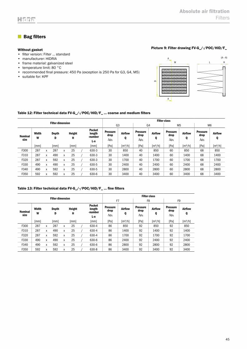
45
Absolute air filtrationFilters
■ Bag filters
Without gasket• filter version: Filter … standard• manufacturer: HIDRIA• frame material: galvanized steel• temperature limit: 80 °C• recommended final pressure: 450 Pa (exception is 250 Pa for G3, G4, M5)• suitable for: KPF
Table 12: Filter technical data FV-G_/-/POC/HID/F_ … coarse and medium filters
Filter dimensionFilter class
G3 G4 M5 M6
Nominal size
WidthW
DepthD
HeightH
Pocket length
-numberL-n
Pressure dropΔpS
AirflowQ
Pressure dropΔpS
AirflowQ
Pressure dropΔpS
AirflowQ
Pressure dropΔpS
AirflowQ
[mm] [mm] [mm] [mm] [Pa] [m³/h] [Pa] [m³/h] [Pa] [m³/h] [Pa] [m³/h]F300 287 x 287 x 25 / 630-3 30 850 40 850 60 850 68 850F310 287 x 490 x 25 / 630-3 30 1400 40 1400 60 1400 68 1400F320 287 x 592 x 25 / 630-3 30 1700 40 1700 60 1700 68 1700F330 490 x 490 x 25 / 630-5 30 2400 40 2400 60 2400 68 2400F340 490 x 592 x 25 / 630-5 30 2800 40 2800 60 2800 68 2800F350 592 x 592 x 25 / 630-6 30 3400 40 3400 60 3400 68 3400
Table 13: Filter technical data FV-G_/-/POC/HID/F_ … fine filters
Filter dimensionFilter class
F7 F8 F9
Nominal size
WidthW
DepthD
HeightH
Pocket length
-numberL-n
Pressure dropΔpS
AirflowQ
Pressure dropΔpS
AirflowQ
Pressure dropΔpS
AirflowQ
[mm] [mm] [mm] [mm] [Pa] [m³/h] [Pa] [m³/h] [Pa] [m³/h]F300 287 x 287 x 25 / 630-4 86 850 92 850 92 850F310 287 x 490 x 25 / 630-4 86 1400 92 1400 92 1400F320 287 x 592 x 25 / 630-4 86 1700 92 1700 92 1700F330 490 x 490 x 25 / 630-6 86 2400 92 2400 92 2400F340 490 x 592 x 25 / 630-6 86 2800 92 2800 92 2800F350 592 x 592 x 25 / 630-8 86 3400 92 3400 92 3400
(A ― A)A
A
W L
D
H
Picture 9: Filter drawing FV-G_/-/POC/HID/F_
Picture 8: Filter drawing H-H_/PL/MDF/HID/F_
Picture 7: Filter drawing H-H_/PO/POC/AAF/F_
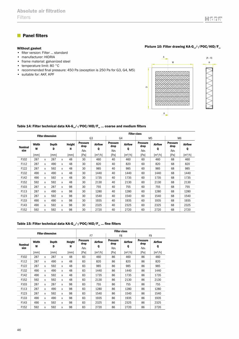
46
Absolute air filtrationFilters
■ Panel filters
Without gasket• filter version: Filter … standard• manufacturer: HIDRIA• frame material: galvanized steel• temperature limit: 80 °C• recommended final pressure: 450 Pa (exception is 250 Pa for G3, G4, M5)• suitable for: AKF, KPF
Table 14: Filter technical data KA-G_/-/POC/HID/F_ … coarse and medium filters
Filter dimensionFilter class
G3 G4 M5 M6
Nominal size
WidthW
DepthD
HeightH
Pressure dropΔpS
AirflowQ
Pressure dropΔpS
AirflowQ
Pressure dropΔpS
AirflowQ
Pressure dropΔpS
AirflowQ
[mm] [mm] [mm] [Pa] [m³/h] [Pa] [m³/h] [Pa] [m³/h] [Pa] [m³/h]F102 287 x 287 x 48 30 460 40 460 60 460 68 460F112 287 x 490 x 48 30 820 40 820 60 820 68 820F122 287 x 592 x 48 30 985 40 985 60 985 68 985F132 490 x 490 x 48 30 1440 40 1440 60 1440 68 1440F142 490 x 592 x 48 30 1735 40 1735 60 1735 68 1735F152 592 x 592 x 48 30 2130 40 2130 60 2130 68 2130F103 287 x 287 x 98 30 755 40 755 60 755 68 755F113 287 x 490 x 98 30 1280 40 1280 60 1280 68 1280F123 287 x 592 x 98 30 1540 40 1540 60 1540 68 1540F133 490 x 490 x 98 30 1935 40 1935 60 1935 68 1935F143 490 x 592 x 98 30 2325 40 2325 60 2325 68 2325F152 592 x 592 x 98 30 2720 40 2720 60 2720 68 2720
Table 15: Filter technical data KA-G_/-/POC/HID/F_ … fine filters
Filter dimensionFilter class
F7 F8 F9
Nominal size
WidthW
DepthD
HeightH
Pressure dropΔpS
AirflowQ
Pressure dropΔpS
AirflowQ
Pressure dropΔpS
AirflowQ
[mm] [mm] [mm] [Pa] [m³/h] [Pa] [m³/h] [Pa] [m³/h]F102 287 x 287 x 48 83 460 86 460 86 460F112 287 x 490 x 48 83 820 86 820 86 820F122 287 x 592 x 48 83 985 86 985 86 985F132 490 x 490 x 48 83 1440 86 1440 86 1440F142 490 x 592 x 48 83 1735 86 1735 86 1735F152 592 x 592 x 48 83 2130 86 2130 86 2130F103 287 x 287 x 98 83 755 86 755 86 755F113 287 x 490 x 98 83 1280 86 1280 86 1280F123 287 x 592 x 98 83 1540 86 1540 86 1540F133 490 x 490 x 98 83 1935 86 1935 86 1935F143 490 x 592 x 98 83 2325 86 2325 86 2325F152 592 x 592 x 98 83 2720 86 2720 86 2720
(A ― A)A
A
W
D
H
Picture 10: Filter drawing KA-G_/-/POC/HID/F_
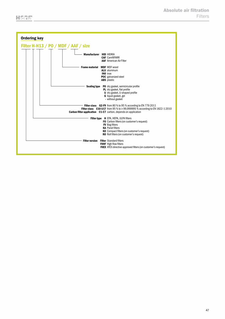
47
Absolute air filtrationFilters
Picture 10: Filter drawing KA-G_/-/POC/HID/F_
Ordering key
Filter H-H13 / PO / MDF / AAF / sizeManufacturer HID HIDRIA
CAF CamfilFARRAAF American Air Filter
Frame material MDF MDF woodALU aluminumINO inox
POC galvanized steelABS plastic
Sealing type PO dry gasket, semicircular profilePL dry gasket, flat profileU dry gasket, U-shaped profileG liquid gasket, gel- without gasket
Filter class G2-F9 from 80 % to 95 % according to EN 779:2011Filter class E10-U17 from 95 % to ≥ 99,999995 % according to EN 1822-1:2010
Carbon filter application C1-C7 carbon, depends on application
Filter type H EPA, HEPA, ULPA filtersFO Carbon filters (on customer’s request)FV Bag filtersKA Panel filtersKO Compact filters (on customer’s request)RO Roll filters (on customer’s request)
Filter version Filter Standard filtersFilHF High flow filtersFilEX ATEX directive approved filters (on customer’s request)
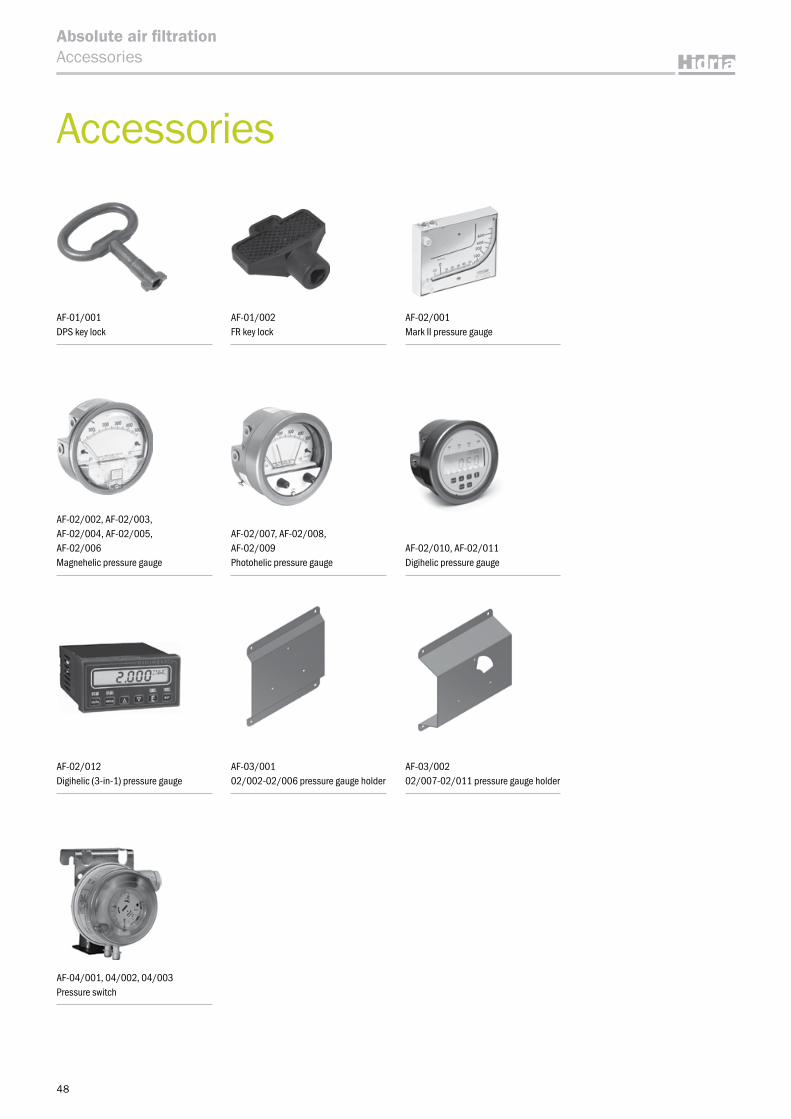
48
Absolute air filtrationAccessories
AF-01/001DPS key lock
AF-02/001Mark II pressure gauge
AF-02/007, AF-02/008,AF-02/009Photohelic pressure gauge
AF-03/00102/002-02/006 pressure gauge holder
AF-01/002FR key lock
AF-02/002, AF-02/003,AF-02/004, AF-02/005,AF-02/006Magnehelic pressure gauge
AF-02/010, AF-02/011Digihelic pressure gauge
AF-02/012Digihelic (3-in-1) pressure gauge
AF-04/001, 04/002, 04/003 Pressure switch
AF-03/00202/007-02/011 pressure gauge holder
Accessories
49
Table 1: Pressure gauge table
Absolute air filtrationAccessories
Technical Data AF-02/001AF-02/002, AF-02/003, AF-02/004, AF-02/005,
AF-02/006AF-02/007, AF-02/008,
AF-02/009 AF-02/010, AF-02/011 AF-02/012
Description Mark II pressure gauge Magnehelic pressure gauge Photohelic pressure gauge Digihelic pressure gauge Digihelic (3-in-1) pressure
gaugeTypeAccuracy
analogue ±3 % full scale
analogue ±2 % full scale
Analogue ±2 % full scale
Digital ±0.5 % at 25 °C
Digital ±0.5 % at 25 °C
Pressure range 10-0-700 Pa
AF-02/002 … 0-250 Pa AF-02/003 … 0-500 Pa AF-02/004 … 0-750 Pa
AF-02/005 … 0-1000 Pa AF-02/006 … 0-1500 Pa
AF-02/007 … 0-500 Pa AF-02/008 … 0-750 Pa
AF-02/009 … 0-1000 Pa
AF-02/010 … 0-622.75 Pa AF-02/011 … 0-1245.5 Pa 0-1245 Pa
Pressure connection 1/8” female NTP 1/8” female NTP 1/8” female NTP 1/8” female NTP 2 male NTP 1/8” plugs for tube Ф4 up to Ф6
Standard accessories 2 male NTP 1/8” plugs for tube Ф4 up to Ф6
2 male NTP 1/8” plugs for tube Ф4 up to Ф6
2 male NTP 1/8” plugs for tube Ф4 up to Ф6
2 male NTP 1/8” plugs for tube Ф4 up to Ф6 /
Temperature range max. 60 °C -6.67 to 60 °C -6.67 to 60 °C 0 to 60 °C 0 to 60 °CHousing material ABS plastic die cast aluminum case die cast aluminum case die cast aluminum case ABS plasticElectrical connection / / 8 wire cable male 15 pin d-Sub screw terminals
Operative voltage / / 24 VDC±10 % 12-28 VDC or 12-28 VAC 50-400Hz
High voltage power:from 100 to 240 VAC 50 to 400 Hz or from 132 to
240 VDCLow voltage power:
24 VDC ±20 %
Relay / /
Switch type: each setpoint has a solid
state relaySwitching voltage:
20-280 VAC (47-63 Hz)Switching current:
0.01 – 1 A
Switch type: 2 SPDT relay
Electrical rating: 1 A @ 30 VAC/VDC
Switch type: 2 SPDT relay
Electrical rating: 8 A @ 240 VAC
Agency approvals / / CE CE CE, UL
Communication / / / / Modbus® RTU, RS485, 9600 baud.
Output / / / 4-20 mA DC into 900 ohms max.
4-20 mA DC into 900 ohms max.
Table 2: Pressure switch table
Technical Data AF-04/001 AF-04/002 AF-04/003
Description Pressure switch Pressure switch Pressure switch
Type QBM81-3 QBM81-5 QBM81-10
Accuracy < ±2.5 Pa < ±5 Pa < ±10 Pa
Pressure range 20…300 Pa 50…500 Pa 100...1000 Pa
Pressure connection Male, Φ 6.2 mm Male, Φ 6.2 mm Male, Φ 6.2 mm
Standard accessories / / /
Temperature range - 30 … + 84 °C - 30 … + 84 °C - 30 … + 84 °C
Housing material Polycarbonate, PVC, ABS Polycarbonate, PVC, ABS Polycarbonate, PVC, ABS
Electrical connection 3 screw terminals 3 screw terminals 3 screw terminals
Operative voltage / / /
Relay
Switch type: single-pole change-overSwitching voltage and
current: AC/DC 24 V ≥ 0,01 AAC 250 V, ≤ 5 (0,8) A
Switch type: single-pole change-overSwitching voltage and
current: AC/DC 24 V ≥ 0,01 AAC 250 V, ≤ 5 (0,8) A
Switch type: single-pole change-overSwitching voltage and
current: AC/DC 24 V ≥ 0,01 AAC 250 V, ≤ 5 (0,8) A
Agency approvals CE conformity to (Low-volta-ge directive 2006/95/EC)
CE conformity to (Low-volta-ge directive 2006/95/EC)
CE conformity to (Low-volta-ge directive 2006/95/EC)
Communication / / /
Output / / /
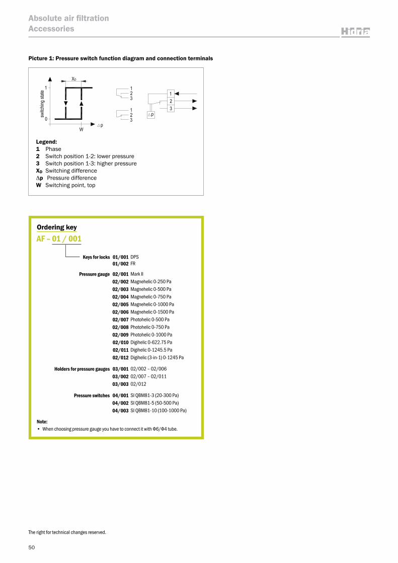
50
Absolute air filtrationAccessories
Ordering key
Keys for locks 01/001 DPS 01/002 FR
Pressure gauge 02/001 Mark II02/002 Magnehelic 0-250 Pa02/003 Magnehelic 0-500 Pa02/004 Magnehelic 0-750 Pa02/005 Magnehelic 0-1000 Pa02/006 Magnehelic 0-1500 Pa02/007 Photohelic 0-500 Pa02/008 Photohelic 0-750 Pa02/009 Photohelic 0-1000 Pa02/010 Digihelic 0-622.75 Pa02/011 Digihelic 0-1245.5 Pa02/012 Digihelic (3-in-1) 0-1245 Pa
Holders for pressure gauges 03/001 02/002 – 02/006 03/002 02/007 – 02/01103/003 02/012
Pressure switches 04/001 SI QBM81-3 (20-300 Pa)04/002 SI QBM81-5 (50-500 Pa)04/003 SI QBM81-10 (100-1000 Pa)
AF – 01 / 001
Note:• When choosing pressure gauge you have to connect it with Ф6/Ф4 tube.
The right for technical changes reserved.
Legend:1 Phase2 Switch position 1-2: lower pressure3 Switch position 1-3: higher pressureXD Switching differenceΔp Pressure differenceW Switching point, top
Picture 1: Pressure switch function diagram and connection terminals

51
Absolute air filtration

Hidria IMP Klima d.o.o.Godovič 1505275 GodovičSloveniaT: +386 5 374 30 00F: +386 5 374 30 82E: [email protected]
Issu
e 05
/13