Embed Size (px)
Citation preview
Acceptable Construction Details, Thermal Bridging and Air Permeability
26/03/2009
Sean Armstrong,Technical Adviser,Building Standards,DEHLG
Outline
� Overview of TGD L
� Overview of Guidance wrt Airtightness and Thermal Bridging
Overview of Acceptable
26/03/2009
� Overview of Acceptable Construction Details

Building Standards - Strategy
Strategy 2008-2010
Promote high quality, safe and sustainable design and construction, notably, through ongoing review of the
26/03/2009
Building Regulations and prioritisation of energy efficiency and eco-design.
Part L
26/03/2009
2008200820082008
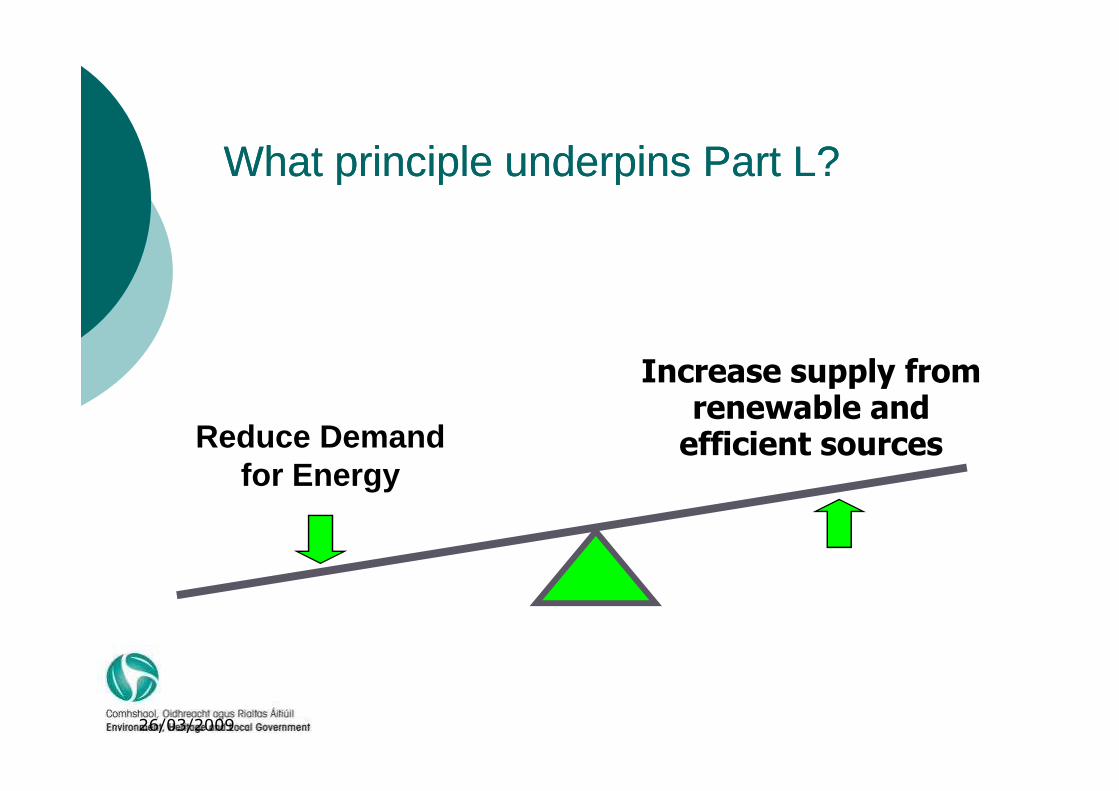
Increase supply from renewable and
What principle underpins Part L?What principle underpins Part L?
26/03/2009
Reduce Demand for Energy
renewable and efficient sources
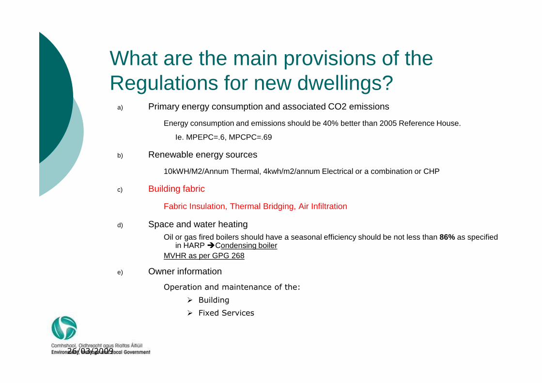
What are the main provisions of the Regulations for new dwellings?
a) Primary energy consumption and associated CO2 emissions
Energy consumption and emissions should be 40% better than 2005 Reference House.
Ie. MPEPC=.6, MPCPC=.69
b) Renewable energy sources
10kWH/M2/Annum Thermal, 4kwh/m2/annum Electrical or a combination or CHP
c) Building fabric
26/03/2009
c) Building fabric
Fabric Insulation, Thermal Bridging, Air Infiltration
d) Space and water heating Oil or gas fired boilers should have a seasonal efficiency should be not less than 86% as specified
in HARP �Condensing boilerMVHR as per GPG 268
e) Owner information
Operation and maintenance of the:
� Building
� Fixed Services
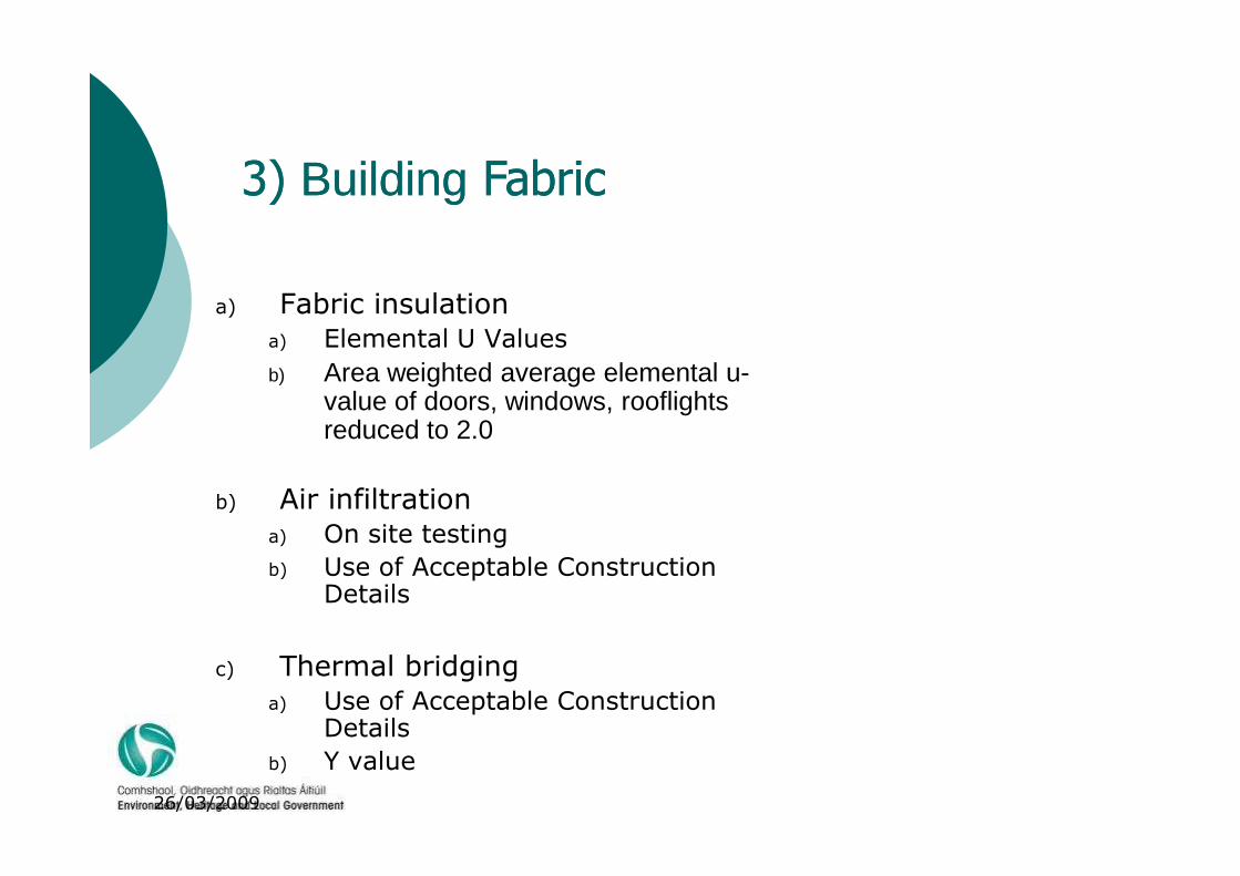
a) Fabric insulationa) Elemental U Values
b) Area weighted average elemental u-value of doors, windows, rooflights reduced to 2.0
3) Building Fabric 3) Building Fabric
26/03/2009
reduced to 2.0
b) Air infiltrationa) On site testing
b) Use of Acceptable Construction Details
c) Thermal bridginga) Use of Acceptable Construction
Details
b) Y value
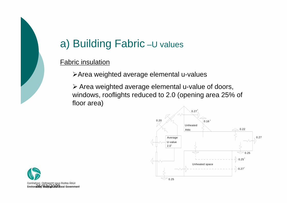
Fabric insulation
�Area weighted average elemental u-values
� Area weighted average elemental u-value of doors, windows, rooflights reduced to 2.0 (opening area 25% of floor area)
a) Building Fabric –U values
26/03/2009
floor area)
A v er ag e U -v a lue 2 .01
Average
U-value 2.0
Unheated
Attic
Unheated space
0.27
0.16
0.22
0.27
0.25
0.27
0.20
0.25
0.25
2
2
2
2
1
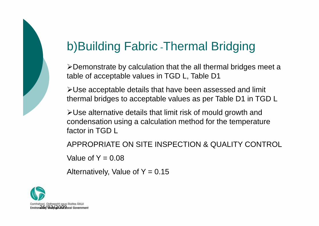
�Demonstrate by calculation that the all thermal bridges meet a table of acceptable values in TGD L, Table D1
�Use acceptable details that have been assessed and limit thermal bridges to acceptable values as per Table D1 in TGD L
�Use alternative details that limit risk of mould growth and
b)Building Fabric -Thermal Bridging
26/03/2009
�Use alternative details that limit risk of mould growth and condensation using a calculation method for the temperature factor in TGD L
APPROPRIATE ON SITE INSPECTION & QUALITY CONTROL
Value of Y = 0.08
Alternatively, Value of Y = 0.15
c) Building Fabric –Air Permeability
1.3.4.1 To avoid excessive heat losses, reasonable care should be taken to limit the air permeability of the envelope of each dwelling. In this context, envelope is the total area of all floors, walls (including windows and doors), and ceilings bordering the dwelling, including elements adjoining other heated or unheated spaces.
26/03/2009
other heated or unheated spaces.
1.3.4.3 Achievement of reasonable levels of air permeability can be facilitated by adopting the standard details referred to in Paragraph 1.3.3.2 (Acceptable Construction Details) above, together with an appropriate performance specification and the on-site inspection regime and related quality control procedures, referred to in that paragraph.
1.3.4.4 Air pressure testing should be carried out on a proportion of dwellings on all development sites. See Sub-section 1.5.4 for details of the test procedure, extent of testing, use of test results inDEAP calculations and appropriate measures to be undertaken where the limit set is not achieved. When tested in accordance with the procedure referred to in Sub-section 1.5.4, a performance level of

Air Leakage
26/03/2009Source: Leeds Metropolitan UniversityLow Carbon Housing Learning Zone
Guidelines to improve air tightness� Design Stage
� Keep it simple! Simple designs are more likely to get built right.
� Decide which layer of the construction provides the air barrier. Stick with this. Use the pen-on-section test to check continuity and to identify key details
� Pay careful attention to the design of junctions between elements toensure continuity of the air barrier.
� Minimise penetrations of the thermal envelope, whether by services orstructure or construction.
26/03/2009
structure or construction.
� Construction Stage
� Ensure that details of all design changes involving elements of theexternal envelope are distributed throughout the design, procurementand construction teams
� It is important that the project programme reflects the requiredsequence for effective formation of the air barrier and insulationinstallation
� Communication and Education – Personnel involved in procurementand constructing the building fabric should understand the need forinsulation continuity and airtightness.
� Quality Control -Quality Assurance (QA) should be extended to check for insulation continuity and airtightness
Thermal BridgingThermal Bridge:Part of the structure of lower thermal resistance that bridges
adjacent parts of higher thermal resistance and which can result in localised cold surfaces on which condensation, mould growth and/or pattern staining can occur.Thermal bridges fall into two categories:(a) Repeating thermal bridges (such as timber joists, mortar joints, and
mullions in curtain walling). The additional heat flow due to the presence of this type of thermal bridge is included in the determination of the U-valueof the particular building element whichcontains these bridges.
26/03/2009
valueof the particular building element whichcontains these bridges.(b) Non-repeating thermal bridges (such as junctions of floor and roof
with the external wall, and details around window and door openings) where the additional heat flow due to the presence of this type of thermal bridge is determined separatelyAcceptable Construction Details address Thermal
Bridge Type B

Main thermal bridges using traditional cavity construction details
Junction of Gable wall with ceiling 7%
26/03/2009
Lintels 23% Sills 23%Jambs 6%
Ground floorperimeter 15%
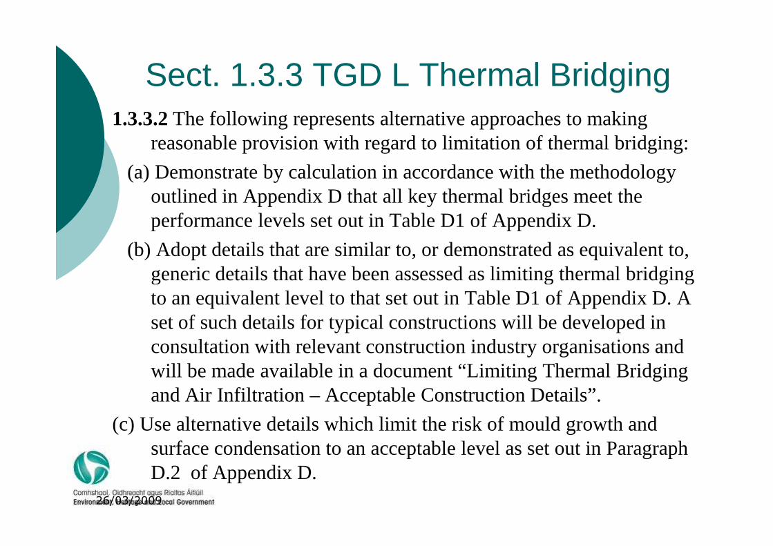
Sect. 1.3.3 TGD L Thermal Bridging1.3.3.2 The following represents alternative approaches to making
reasonable provision with regard to limitation of thermal bridging:
(a) Demonstrate by calculation in accordance with the methodology outlined in Appendix D that all key thermal bridges meet theperformance levels set out in Table D1 of Appendix D.
(b) Adopt details that are similar to, or demonstrated as equivalent to, generic detailsthat have been assessed as limiting thermalbridging
26/03/2009
generic detailsthat have been assessed as limiting thermalbridging to an equivalent level to that set out in Table D1 of Appendix D. A set of such details for typical constructions will be developed in consultation with relevant construction industry organisations and will be made available in a document “Limiting Thermal Bridging and Air Infiltration – Acceptable Construction Details”.
(c) Use alternative details which limit the risk ofmould growth and surface condensation to an acceptable level as set out in Paragraph D.2 of Appendix D.
Deap Calculations
1.3.3.3 DEAP allows for thermal bridges by including an allowance for additional heat loss due to thermal bridging, expressed as amultiplier (y) applied to the total exposed surface area.
� Where provision for thermal bridging is made in accordance with options (a) or (b) of Paragraph1.3.3.2, this multiplier
26/03/2009
with options (a) or (b) of Paragraph1.3.3.2, this multiplier should be taken as 0.08.
� Where option (c) of Paragraph 1.3.3.2 is used, it will benecessary to allow for each thermal bridge separately in the calculation.
� Alternatively a multiplier of 0.15 may be used.
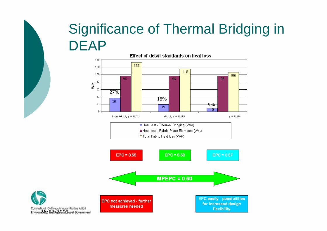
Significance of Thermal Bridging in DEAP
27%
16%9%
26/03/2009
Methodology outlined in Appendix D
� The procedure to establish linear thermal
transmittance () is outlined in BRE IP 1/06.� Modelling Software should perform to IS EN ISO 10211 Parts
1 and 2. Several packages are available that meet this requirement. –Therm (free), HEAT, Physibel
� The guidance in BRE Report BR 497 Conventions for
26/03/2009
� The guidance in BRE Report BR 497 Conventions for calculating linear thermal transmittance and temperature factors on inputting parameters should be used for modelling. This allows different users of the same software package andusers of different software packages can obtain correct and consistent results.
Thermal Bridge and Linear Thermal Transmittance
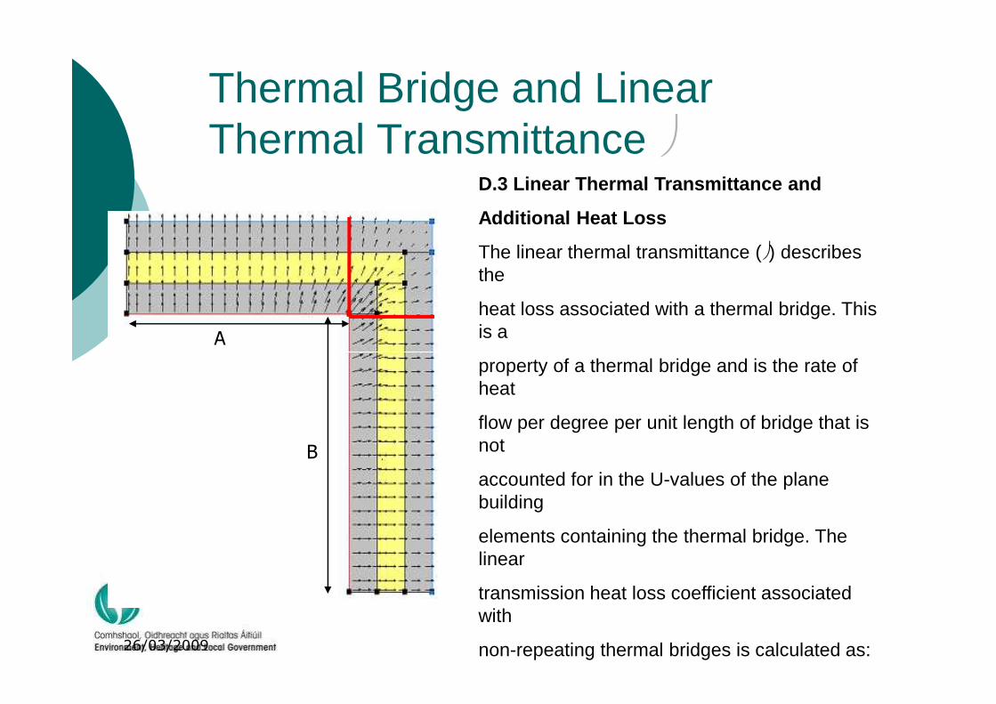
D.3 Linear Thermal Transmittance and
Additional Heat Loss
The linear thermal transmittance () describes the
heat loss associated with a thermal bridge. This is aA
26/03/2009
property of a thermal bridge and is the rate of heat
flow per degree per unit length of bridge that is not
accounted for in the U-values of the plane building
elements containing the thermal bridge. The linear
transmission heat loss coefficient associated with
non-repeating thermal bridges is calculated as:
B
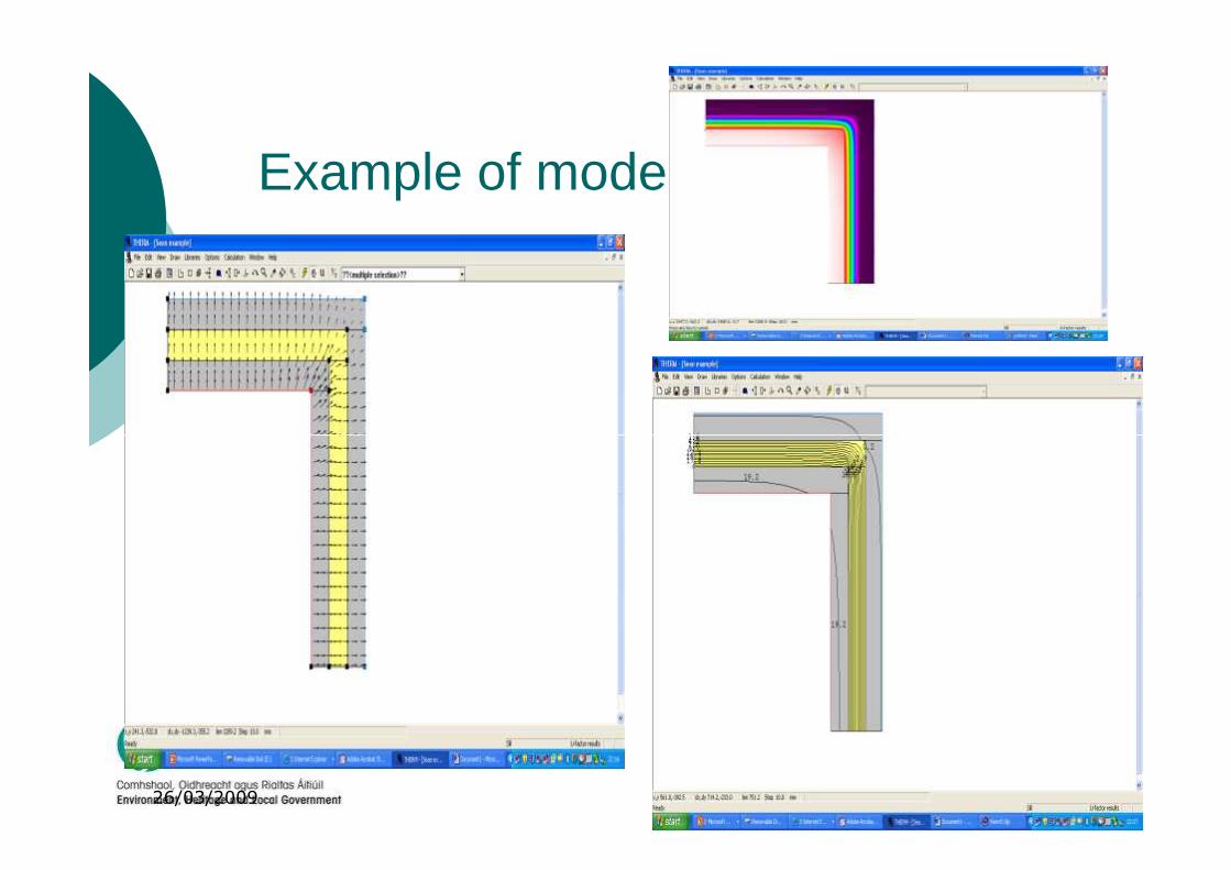
Example of models
26/03/2009
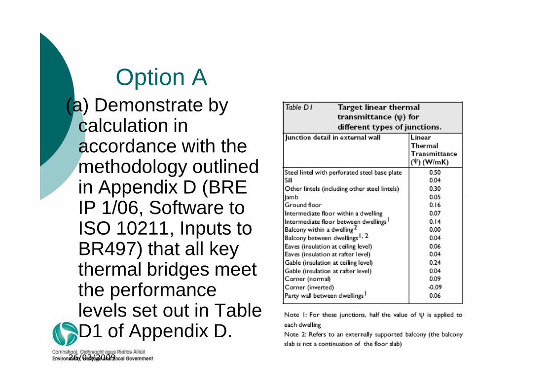
Option A(a) Demonstrate by
calculation in accordance with the methodology outlined in Appendix D (BRE
26/03/2009
in Appendix D (BRE IP 1/06, Software to ISO 10211, Inputs to BR497) that all key thermal bridges meetthe performance levels set out in Table D1 of Appendix D.
Option C.
Use alternative details which limit the risk of mould growth and surface condensation to an acceptable level as set out in Paragraph D.2 ofAppendix DD.2 Mould Growth and Surface CondensationThe temperature factor (fRsi) is defined as follows:
fRsi = (Tsi – Te) / (Ti – Te) where:
Tsi = minimum internal surface temperature,
26/03/2009
Te = external temperature, and
Ti = internal temperature.
For dwellings, the value of fRsi should be greater than or equal to 0.75 so as to avoid the risk of mould growth and surface condensation.
For three dimensional corners of ground floors this value maybe reduced to 0.70, for all points within 10 mm of the point of lowest fRsi
Where option (c) of Paragraph 1.3.3.2 is used, it will be necessary to allow for each thermal bridge separately in the calculation of a value for y.
Option B
� Adopt details that are similar to, or demonstrated as equivalent to, generic details that have been assessed as limiting thermal bridging to an equivalent level to that set out in Table D1 of Appendix D. A set of such details for typical constructions will be developed in consultation
26/03/2009
typical constructions will be developed in consultation with relevant construction industry organisations and will be made available in a document “Limiting ThermalBridging and Air Infiltration – Acceptable Construction Details”.
Acceptable Construction Details Format
� Details have been developed by DEHLG, HomeBond and SEI.
� They were developed in Consultation with an Industry Working Group made up of represenatives from different Sectors of the Construction Industry.
26/03/2009
� The guide is presented in 2 sections.� Section 1 discusses the general theory of insulation
continuity and airtightness in construction.� Section 2, in seven separate parts, provides
indicative detail drawings of thermal insulation and airtightness provisions for specific construction interfaces.
Acceptable Construction Details –Section 1
� Explains how to achieve minimise thermal bridges at design stage and construction stage
� Provides an Index to drawings
� Explains how thermal bridging multiplier (y) can be used in DEAP
� Provides pictures and guidelines of best practice with regards to
26/03/2009
Provides pictures and guidelines of best practice with regards to achieving airtightness in Buildings
� Provides examples of how to calculate value for y for TGD L example
� Provides an appendix 2 of Psi (ψ) values for commonly used details which can be used when value for y is obtained by calculation.
Acceptable Construction Details –Section 2
� Consists of drawings for each construction type. 21-25 Drawings for each construction type and 4 common drawingsType 1 Cavity wall insulation
Type 2 External insulation
Type 3 Internal insulation
26/03/2009
Type 3 Internal insulation
Type 4 Timber Frame
Type 5 Steel Frame
Type 6 Hollow Block Internal Insulation
Type G General Details(common to all constructions)
� 21-25 Drawings for each construction type and 4 common drawings

Details -Introduction PageThe image cannot be displayed. Your computer may not have enough memory to open the image, or the image may have been corrupted. Restart your computer, and then open the file again. If the red x still appears, you may have to delete the image and then insert it again.
26/03/2009
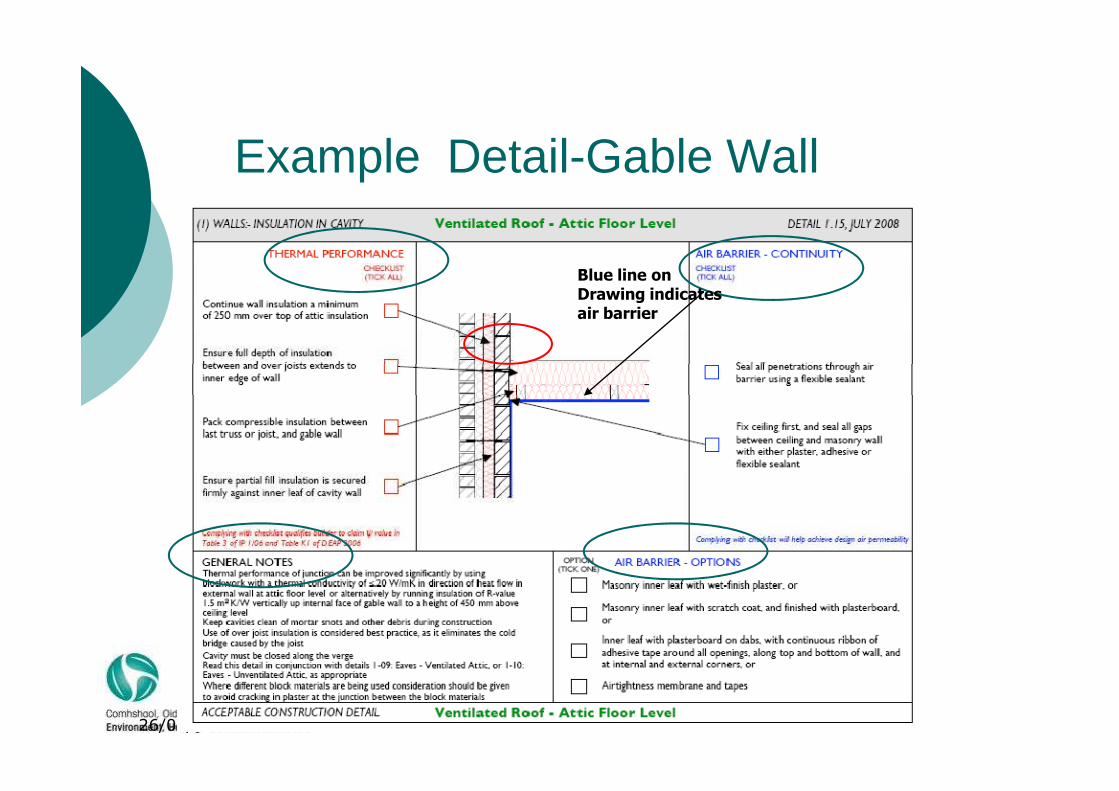
Example Detail-Gable Wall
Blue line onDrawing indicates air barrier
26/03/2009
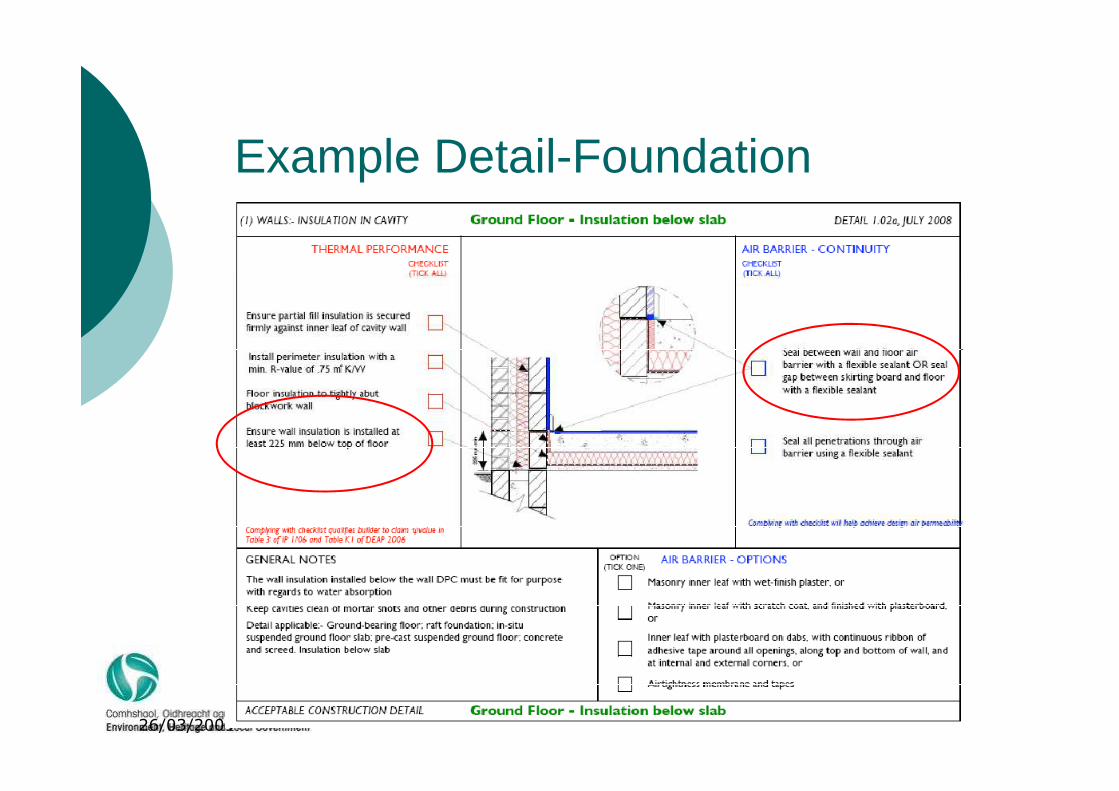
Example Detail-Foundation
26/03/2009
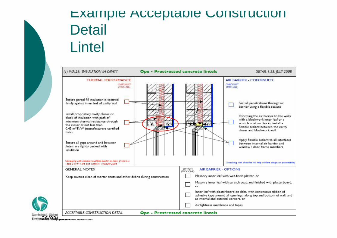
Example Acceptable Construction DetailLintel
26/03/2009

Deap calculations
� Heat loss through thermal bridging is not accounted forin the u-value calculation for the plane buildingelements containing the thermal bridge and thereforemust be evaluated separately. It is usually expressedin terms of a fraction known as y. In order todetermine the value of y to be used in an energy ratingcalculation, an assessor has three choices:
26/03/2009
determine the value of y to be used in an energy ratingcalculation, an assessor has three choices:
a)Use 0.15 where no calculations have been performed andwhere Acceptable Construction Details have not beenused;
b) Use 0.08 where the Acceptable Construction Details havebeen used in all details;
c) Or use a value for y which can be determined through calculation, this procedure must be followed where a value for y other than those outlined above is used by the assessor; sample calculations are provided later in this section
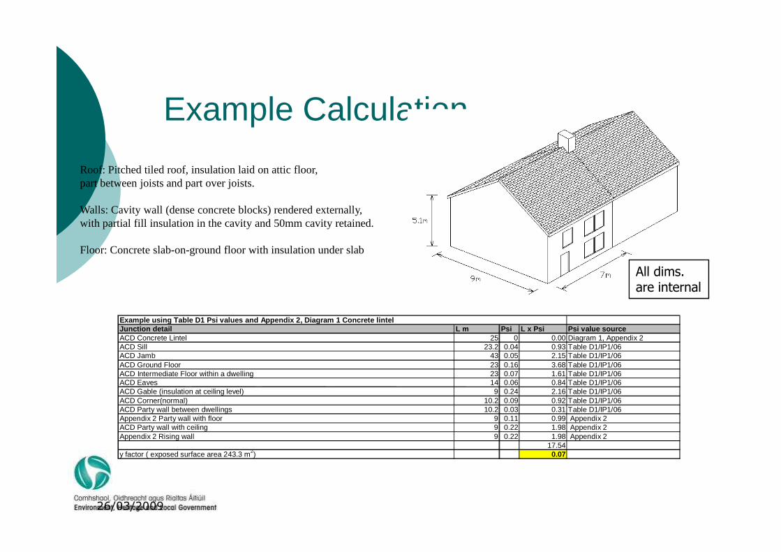
Example Calculation
Roof: Pitched tiled roof, insulation laid on attic floor, part between joists and part over joists.
Walls: Cavity wall (dense concrete blocks) rendered externally, with partial fill insulation in the cavity and 50mm cavity retained.
Floor: Concrete slab-on-ground floor with insulation under slab
All dims.
26/03/2009
Example using Table D1 Psi values and Appendix 2, Diagram 1 Concrete lintel Junction detail L m Psi L x Psi Psi value source ACD Concrete Lintel 25 0 0.00 Diagram 1, Appendix 2 ACD Sill 23.2 0.04 0.93 Table D1/IP1/06 ACD Jamb 43 0.05 2.15 Table D1/IP1/06 ACD Ground Floor 23 0.16 3.68 Table D1/IP1/06 ACD Intermediate Floor within a dwelling 23 0.07 1.61 Table D1/IP1/06 ACD Eaves 14 0.06 0.84 Table D1/IP1/06 ACD Gable (insulation at ceiling level) 9 0.24 2.16 Table D1/IP1/06 ACD Corner(normal) 10.2 0.09 0.92 Table D1/IP1/06 ACD Party wall between dwellings 10.2 0.03 0.31 Table D1/IP1/06 Appendix 2 Party wall with floor 9 0.11 0.99 Appendix 2 ACD Party wall with ceiling 9 0.22 1.98 Appendix 2 Appendix 2 Rising wall 9 0.22 1.98 Appendix 2
17.54 y factor ( exposed surface area 243.3 m2) 0.07
All dims.are internal
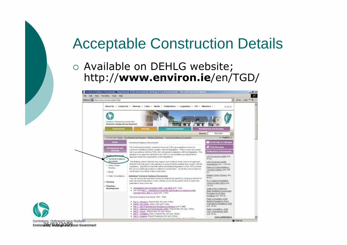
Acceptable Construction Details
� Available on DEHLG website;http://www.environ.ie/en/TGD/
26/03/2009

Draft document available on website
26/03/2009