Embed Size (px)
Citation preview
1
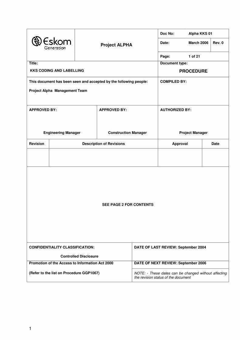
Doc No: Alpha KKS 01
Date: March 2006 Rev. 0
Project ALPHA
Page: 1 of 21
Title:
KKS CODING AND LABELLING
Document type:
PROCEDURE
This document has been seen and accepted by the following people:
Project Alpha Management Team
COMPILED BY:
APPROVED BY:
Engineering Manager
APPROVED BY:
Construction Manager
AUTHORIZED BY:
Project Manager
Revision Description of Revisions Approval Date
SEE PAGE 2 FOR CONTENTS
CONFIDENTIALITY CLASSIFICATION:
Controlled Disclosure
DATE OF LAST REVIEW: September 2004
DATE OF NEXT REVIEW: September 2006 Promotion of the Access to Information Act 2000
(Refer to the list on Procedure GGP1067) NOTE: - These dates can be changed without affecting the revision status of the document
Document Number: Alpha KKS 01 PROJECT ALPHA KKS CODING AND LABELLING Revision: 0 Page 2of 21
2
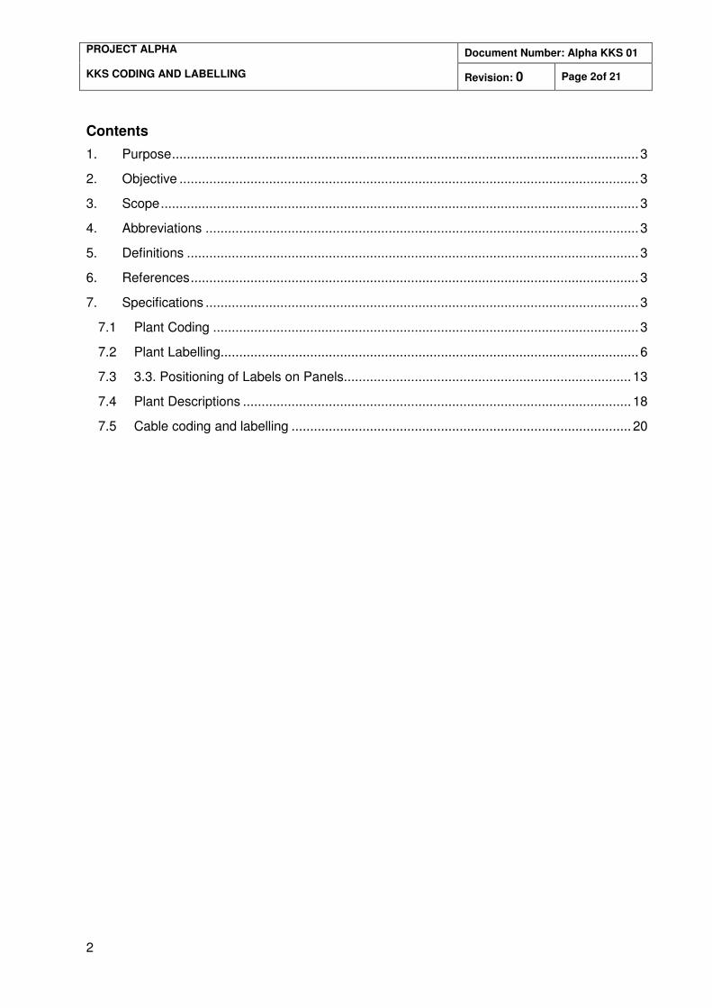
Contents
1. Purpose.............................................................................................................................3
2. Objective ...........................................................................................................................3
3. Scope................................................................................................................................3
4. Abbreviations ....................................................................................................................3
5. Definitions .........................................................................................................................3
6. References........................................................................................................................3
7. Specifications ....................................................................................................................3
7.1 Plant Coding ..................................................................................................................3
7.2 Plant Labelling................................................................................................................6
7.3 3.3. Positioning of Labels on Panels............................................................................. 13
7.4 Plant Descriptions ........................................................................................................ 18
7.5 Cable coding and labelling ........................................................................................... 20
Document Number: Alpha KKS 01 PROJECT ALPHA KKS CODING AND LABELLING Revision: 0 Page 3of 21
3
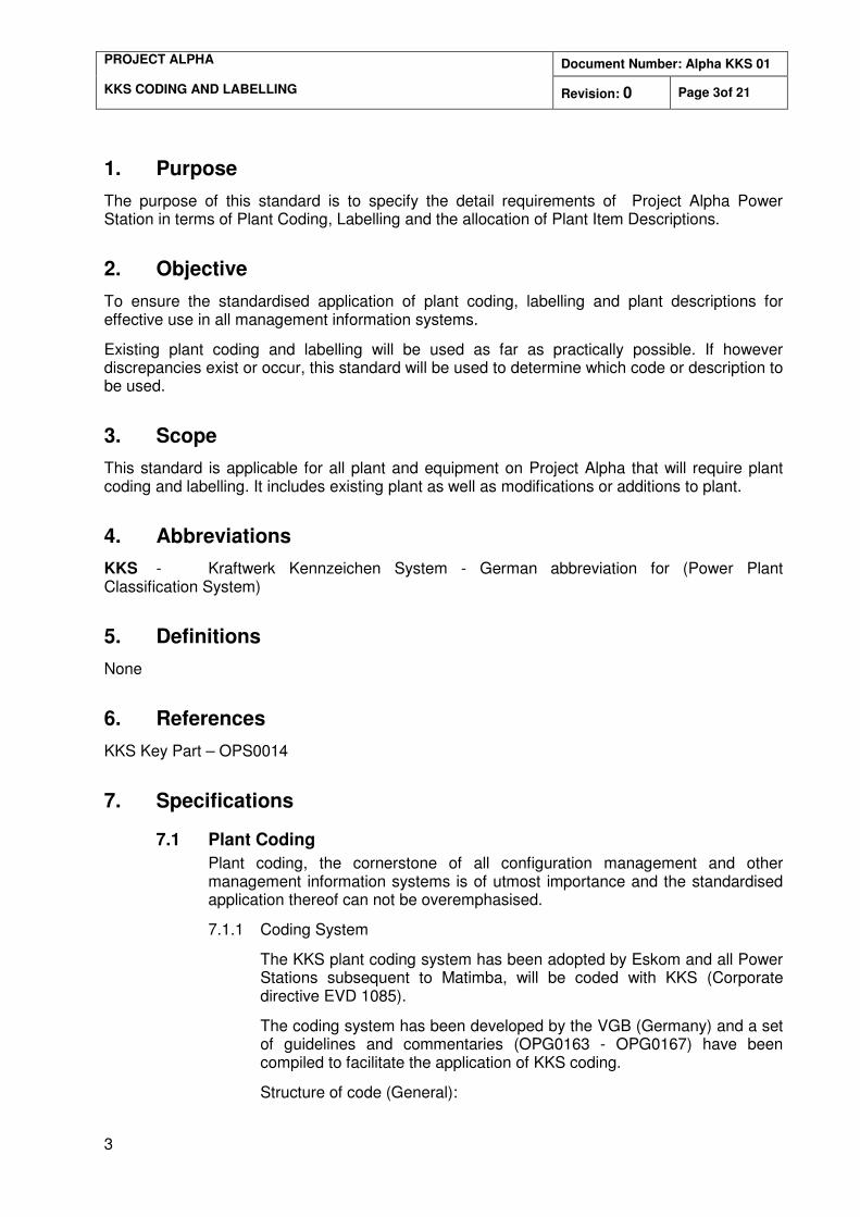
1. Purpose
The purpose of this standard is to specify the detail requirements of Project Alpha Power Station in terms of Plant Coding, Labelling and the allocation of Plant Item Descriptions.
2. Objective
To ensure the standardised application of plant coding, labelling and plant descriptions for effective use in all management information systems.
Existing plant coding and labelling will be used as far as practically possible. If however discrepancies exist or occur, this standard will be used to determine which code or description to be used.
3. Scope
This standard is applicable for all plant and equipment on Project Alpha that will require plant coding and labelling. It includes existing plant as well as modifications or additions to plant.
4. Abbreviations
KKS - Kraftwerk Kennzeichen System - German abbreviation for (Power Plant Classification System)
5. Definitions
None
6. References
KKS Key Part – OPS0014
7. Specifications
7.1 Plant Coding
Plant coding, the cornerstone of all configuration management and other management information systems is of utmost importance and the standardised application thereof can not be overemphasised.
7.1.1 Coding System
The KKS plant coding system has been adopted by Eskom and all Power Stations subsequent to Matimba, will be coded with KKS (Corporate directive EVD 1085).
The coding system has been developed by the VGB (Germany) and a set of guidelines and commentaries (OPG0163 - OPG0167) have been compiled to facilitate the application of KKS coding.
Structure of code (General):
Document Number: Alpha KKS 01 PROJECT ALPHA KKS CODING AND LABELLING Revision: 0 Page 4of 21
4
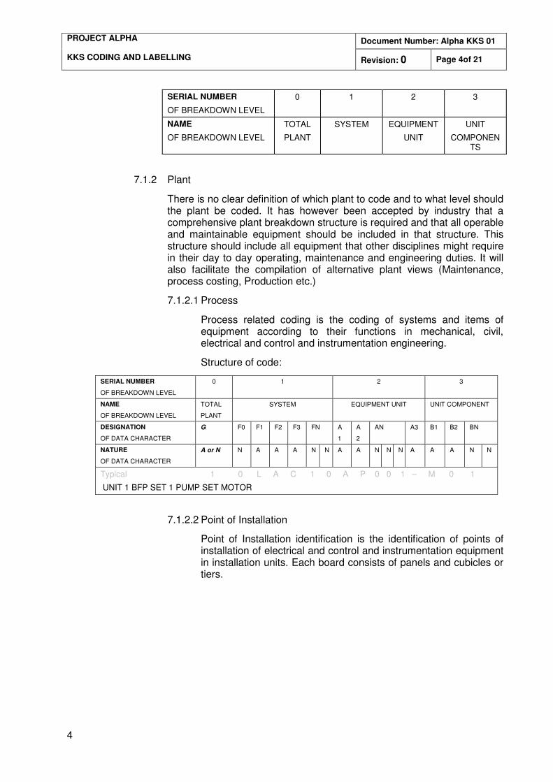
SERIAL NUMBER
OF BREAKDOWN LEVEL
0 1 2 3
NAME
OF BREAKDOWN LEVEL
TOTAL
PLANT
SYSTEM EQUIPMENT
UNIT
UNIT
COMPONENTS
7.1.2 Plant
There is no clear definition of which plant to code and to what level should the plant be coded. It has however been accepted by industry that a comprehensive plant breakdown structure is required and that all operable and maintainable equipment should be included in that structure. This structure should include all equipment that other disciplines might require in their day to day operating, maintenance and engineering duties. It will also facilitate the compilation of alternative plant views (Maintenance, process costing, Production etc.)
7.1.2.1 Process
Process related coding is the coding of systems and items of equipment according to their functions in mechanical, civil, electrical and control and instrumentation engineering.
Structure of code:
SERIAL NUMBER
OF BREAKDOWN LEVEL
0 1 2 3
NAME
OF BREAKDOWN LEVEL
TOTAL
PLANT
SYSTEM EQUIPMENT UNIT UNIT COMPONENT
DESIGNATION
OF DATA CHARACTER
G F0 F1 F2 F3 FN A
1
A
2
AN A3 B1 B2 BN
NATURE
OF DATA CHARACTER
A or N N A A A N N A A N N N A A A N N
Typical 1 0 L A C 1 0 A P 0 0 1 – M 0 1
UNIT 1 BFP SET 1 PUMP SET MOTOR
7.1.2.2 Point of Installation
Point of Installation identification is the identification of points of installation of electrical and control and instrumentation equipment in installation units. Each board consists of panels and cubicles or tiers.
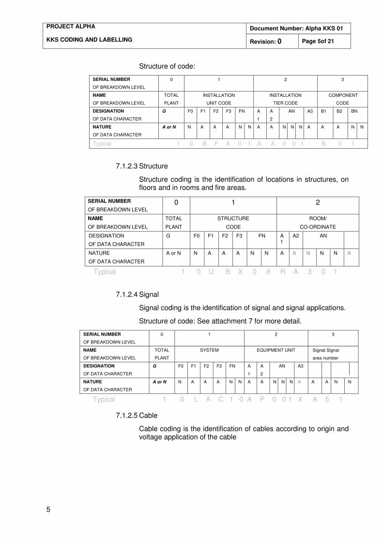
Document Number: Alpha KKS 01 PROJECT ALPHA KKS CODING AND LABELLING Revision: 0 Page 5of 21
5
Structure of code:
SERIAL NUMBER
OF BREAKDOWN LEVEL
0 1 2 3
NAME
OF BREAKDOWN LEVEL
TOTAL
PLANT
INSTALLATION
UNIT CODE
INSTALLATION
TIER CODE
COMPONENT
CODE
DESIGNATION
OF DATA CHARACTER
G F0 F1 F2 F3 FN A
1
A
2
AN A3 B1 B2 BN
NATURE
OF DATA CHARACTER
A or N N A A A N N A A N N N A A A N N
Typical 1 0 B F A 0 1 A A 0 0 1 - B 0 1
7.1.2.3 Structure
Structure coding is the identification of locations in structures, on floors and in rooms and fire areas.
SERIAL NUMBER
OF BREAKDOWN LEVEL 0 1 2
NAME
OF BREAKDOWN LEVEL TOTAL
PLANT
STRUCTURE
CODE
ROOM/
CO-ORDINATE
DESIGNATION
OF DATA CHARACTER
G F0 F1 F2 F3 FN A1
A2 AN
NATURE
OF DATA CHARACTER
A or N N A A A N N A A N N N A
Typical 1 0 U B X 0 8 R A 3 0 1
7.1.2.4 Signal
Signal coding is the identification of signal and signal applications.
Structure of code: See attachment 7 for more detail.
SERIAL NUMBER
OF BREAKDOWN LEVEL
0 1 2 3
NAME
OF BREAKDOWN LEVEL
TOTAL
PLANT
SYSTEM EQUIPMENT UNIT Signal Signal
area number
DESIGNATION
OF DATA CHARACTER
G F0 F1 F2 F3 FN A
1
A
2
AN A3
NATURE
OF DATA CHARACTER
A or N N A A A N N A A N N N A A A N N
Typical 1 0 L A C 1 0 A P 0 0 1 X A 5 1
7.1.2.5 Cable
Cable coding is the identification of cables according to origin and voltage application of the cable
Document Number: Alpha KKS 01 PROJECT ALPHA KKS CODING AND LABELLING Revision: 0 Page 6of 21
6
Cable NO Format:
Classifying Element Numbering Element
Process Related Code Cable Number
NNAAA i.e. 00ETK NNNN i.e. 8001
OR
Point of Installation Code Cable Number
NNAAA i.e. 00EYG NNNN i.e. 8001
7.2 Plant Labelling
Plant labelling is the physical label that is fixed to the plant. The purpose of plant label is to unambiguously distinguish between plant items and to ensure that a one to one correlation exist between the identification of the item on the plant and the identification of the item in the management information systems
7.2.1 Labels
Because of the diversity of plant that has to be labelled one cannot standardise on the material, size and type of label. This standard will therefore distinguish between the different plant areas and types of labels to be used.
7.2.1.1 Label Material
The following material will be used for the different plant areas:
- Boiler – Anodised Alluminium - Turbine – Anodised Alluminium - Ash – Anodised Alluminium - Coal – Anodised Alluminium - WTP – Stainless Steel - Switchgear and Panels – White Graflux - Internal panels/cubicles – Colour coded plastic - Control panels and desks – Laminated paper
7.2.1.2 Ergonomic Requirements
Consistency will be maintained when fitting new labels regarding material, method of fitting, etc and may overrule above statement (7.2.1.1).
Labels will be fitted in such a manner as to not hamper routine Operations and Maintenance activities.
Labels should be fitted in a position where they can be easily seen without compromising identity of exact equipment.
Labels will not be attached to removable equipment (ie Lagging) but will be attached to non-removable structures as near to it as possible, without compromising identity of exact equipment.
All labels to be mounted on a vertical plane to minimize dirt build-up
Document Number: Alpha KKS 01 PROJECT ALPHA KKS CODING AND LABELLING Revision: 0 Page 7of 21
7
All labels will be mounted so that the text runs in a horizontal plane, reading from left to right to the nearest fixed point that is being described.
For labels that have to be mounted vertically due to space constraints, the method of text reading will be from bottom to top. This excludes cable labels.
Label fixing devices e.g. rivets, self tappers, adhesives, ext will not penetrate the equipment housing or constitute a potential source of corrosion.
All labels will be secure, ie not move under reasonable pressure.
Labels or backplates/brackets will not have sharp edges or protrude in such a way as to pose a safety risk.
Valve labels will not be installed on hand wheels.
Labels will not cover equipment specification plates.
7.2.1.3 Environmental factors
All labels will be able to withstand the following for at least 30 years:
- Rain - Hail - Temperature variance as required by plant - Wind and Dust erosion - Ultra Violet rays(sun) - Corrosion
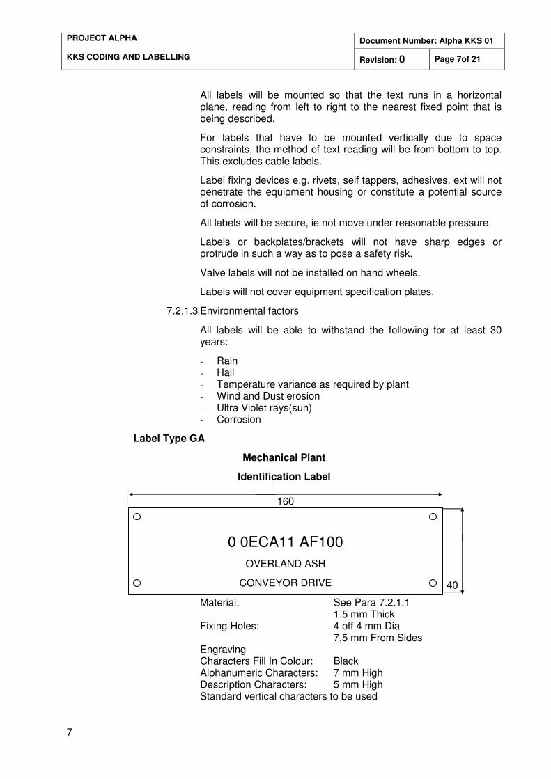
Label Type GA
Mechanical Plant
Identification Label
Material: See Para 7.2.1.1 1.5 mm Thick
Fixing Holes: 4 off 4 mm Dia 7,5 mm From Sides Engraving Characters Fill In Colour: Black Alphanumeric Characters: 7 mm High Description Characters: 5 mm High Standard vertical characters to be used
0 0ECA11 AF100
OVERLAND ASH
CONVEYOR DRIVE
40
160
Document Number: Alpha KKS 01 PROJECT ALPHA KKS CODING AND LABELLING Revision: 0 Page 8of 21
8
Narrow (condensed), broad (extended) characters are not acceptable
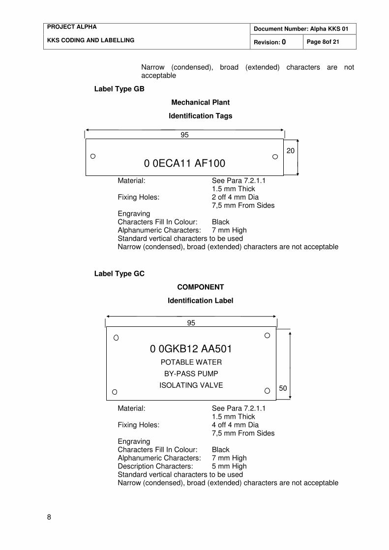
Label Type GB
Mechanical Plant
Identification Tags
Material: See Para 7.2.1.1 1.5 mm Thick Fixing Holes: 2 off 4 mm Dia 7,5 mm From Sides Engraving Characters Fill In Colour: Black Alphanumeric Characters: 7 mm High Standard vertical characters to be used Narrow (condensed), broad (extended) characters are not acceptable
Label Type GC
COMPONENT
Identification Label
Material: See Para 7.2.1.1 1.5 mm Thick Fixing Holes: 4 off 4 mm Dia 7,5 mm From Sides Engraving Characters Fill In Colour: Black Alphanumeric Characters: 7 mm High Description Characters: 5 mm High Standard vertical characters to be used Narrow (condensed), broad (extended) characters are not acceptable
0 0ECA11 AF100
20
95
0 0GKB12 AA501
POTABLE WATER
BY-PASS PUMP
ISOLATING VALVE
50
95
Document Number: Alpha KKS 01 PROJECT ALPHA KKS CODING AND LABELLING Revision: 0 Page 9of 21
9
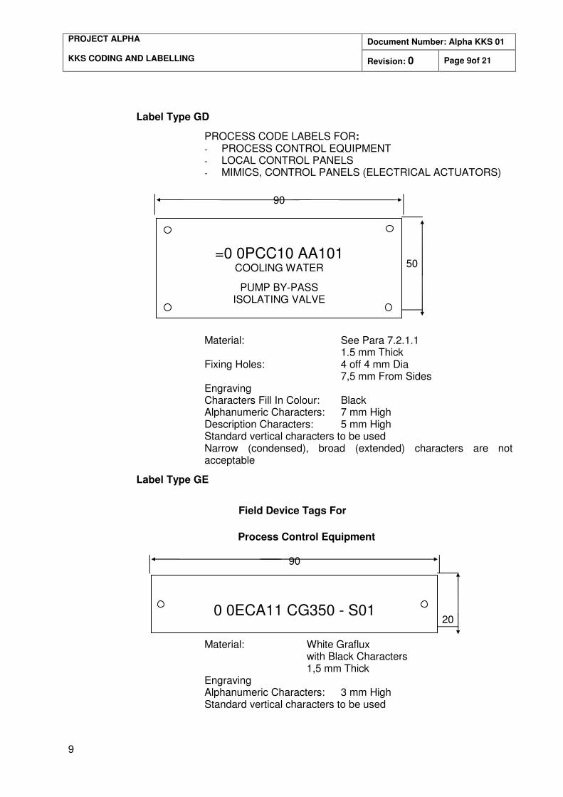
Label Type GD
PROCESS CODE LABELS FOR: - PROCESS CONTROL EQUIPMENT - LOCAL CONTROL PANELS - MIMICS, CONTROL PANELS (ELECTRICAL ACTUATORS)
Material: See Para 7.2.1.1 1.5 mm Thick Fixing Holes: 4 off 4 mm Dia 7,5 mm From Sides Engraving Characters Fill In Colour: Black Alphanumeric Characters: 7 mm High Description Characters: 5 mm High Standard vertical characters to be used Narrow (condensed), broad (extended) characters are not acceptable
Label Type GE
Field Device Tags For
Process Control Equipment
Material: White Graflux with Black Characters 1,5 mm Thick Engraving Alphanumeric Characters: 3 mm High Standard vertical characters to be used
0 0ECA11 CG350 - S01
20
90
=0 0PCC10 AA101
COOLING WATER
PUMP BY-PASS ISOLATING VALVE
50
90

Document Number: Alpha KKS 01 PROJECT ALPHA KKS CODING AND LABELLING Revision: 0 Page 10of 21
10
Narrow (condensed), broad (extended) characters are not acceptable
Document Number: Alpha KKS 01 PROJECT ALPHA KKS CODING AND LABELLING Revision: 0 Page 11of 21
11
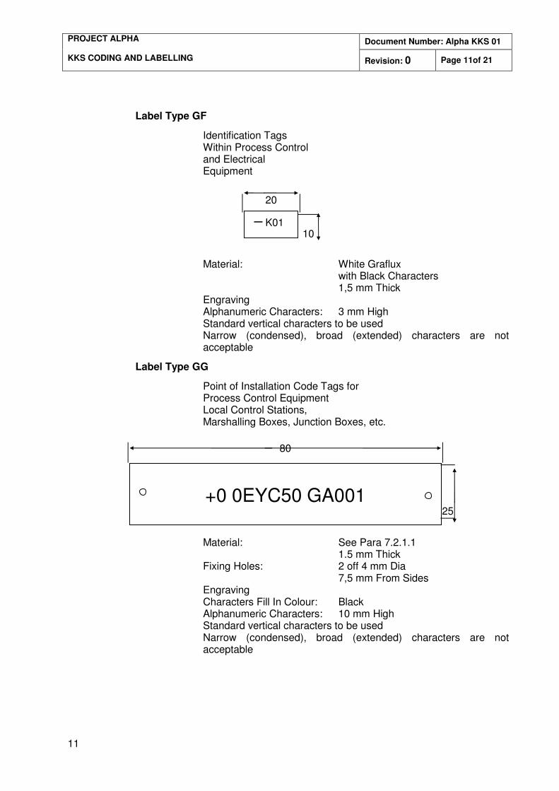
Label Type GF
Identification Tags Within Process Control and Electrical Equipment
Material: White Graflux with Black Characters 1,5 mm Thick Engraving Alphanumeric Characters: 3 mm High Standard vertical characters to be used Narrow (condensed), broad (extended) characters are not acceptable
Label Type GG
Point of Installation Code Tags for Process Control Equipment Local Control Stations, Marshalling Boxes, Junction Boxes, etc.
Material: See Para 7.2.1.1 1.5 mm Thick Fixing Holes: 2 off 4 mm Dia 7,5 mm From Sides Engraving Characters Fill In Colour: Black Alphanumeric Characters: 10 mm High Standard vertical characters to be used Narrow (condensed), broad (extended) characters are not acceptable
– K01
20
10
+0 0EYC50 GA001
25
80
Document Number: Alpha KKS 01 PROJECT ALPHA KKS CODING AND LABELLING Revision: 0 Page 12of 21
12
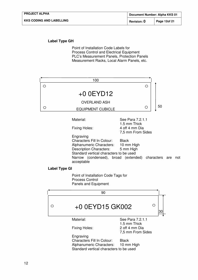
Label Type GH
Point of Installation Code Labels for Process Control and Electrical Equipment PLC’s Measurement Panels, Protection Panels Measurement Racks, Local Alarm Panels, etc.
Material: See Para 7.2.1.1 1.5 mm Thick Fixing Holes: 4 off 4 mm Dia 7,5 mm From Sides Engraving Characters Fill In Colour: Black Alphanumeric Characters: 10 mm High Description Characters: 5 mm High Standard vertical characters to be used Narrow (condensed), broad (extended) characters are not acceptable
Label Type GI
Point of Installation Code Tags for Process Control Panels and Equipment
Material: See Para 7.2.1.1 1.5 mm Thick Fixing Holes: 2 off 4 mm Dia 7,5 mm From Sides Engraving Characters Fill In Colour: Black Alphanumeric Characters: 10 mm High Standard vertical characters to be used
+0 0EYD12 OVERLAND ASH
EQUIPMENT CUBICLE
50
100
+0 0EYD15 GK002
30
90
Document Number: Alpha KKS 01 PROJECT ALPHA KKS CODING AND LABELLING Revision: 0 Page 13of 21
13
Narrow (condensed), broad (extended) characters are not acceptable
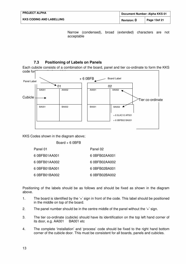
7.3 Positioning of Labels on Panels
Each cubicle consists of a combination of the board, panel and tier co-ordinate to form the KKS code for the particular cubicle.
Cubicle
KKS Codes shown in the diagram above;
Board + 6 0BFB
Panel 01 Panel 02
6 0BFB01AA001 6 0BFB02AA001
6 0BFB01AA002 6 0BFB02AA002
6 0BFB01BA001 6 0BFB02BA001
6 0BFB01BA002 6 0BFB02BA002
Positioning of the labels should be as follows and should be fixed as shown in the diagram above.
1. The board is identified by the ‘+’ sign in front of the code. This label should be positioned in the middle on top of the board.
2. The panel number should be in the centre middle of the panel without the ‘+’ sign.
3. The tier co-ordinate (cubicle) should have its identification on the top left hand corner of its door, e.g. AA001 BA001 etc
4. The complete ‘installation’ and ‘process’ code should be fixed to the right hand bottom corner of the cubicle door. This must be consistent for all boards, panels and cubicles.
AA001 AA002
BA001 BA002
AA001 AA002
BA001 BA002
01 02
+ 6 0BFB Board Label Panel Label
Tier co-ordinate
= 6 0LAC10 AP001
+ 6 0BFB02 BA001
Document Number: Alpha KKS 01 PROJECT ALPHA KKS CODING AND LABELLING Revision: 0 Page 14of 21
14
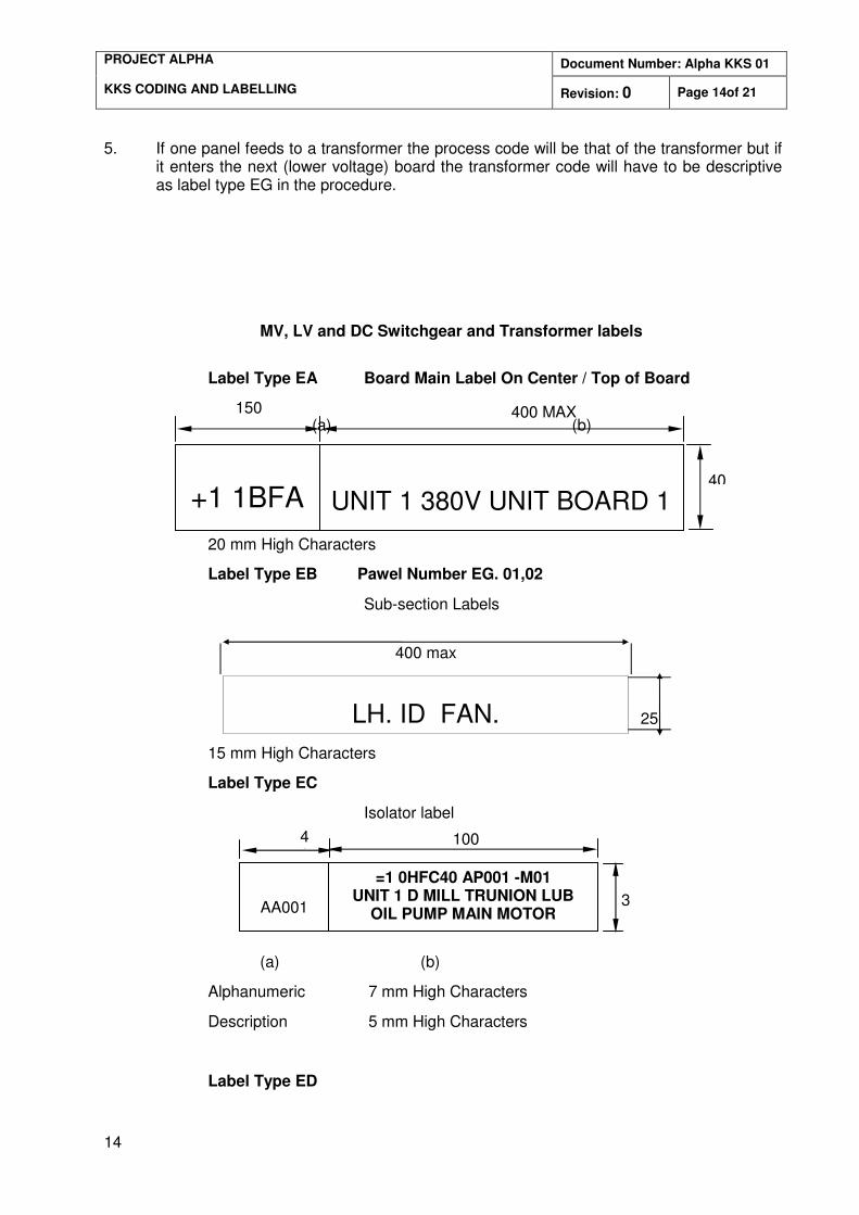
5. If one panel feeds to a transformer the process code will be that of the transformer but if it enters the next (lower voltage) board the transformer code will have to be descriptive as label type EG in the procedure.
MV, LV and DC Switchgear and Transformer labels
Label Type EA Board Main Label On Center / Top of Board
(a) (b)
20 mm High Characters
Label Type EB
20 mm High Characters
Label Type EB Pawel Number EG. 01,02
Sub-section Labels
15 mm High Characters
Label Type EC
Isolator label
(a) (b)
Alphanumeric 7 mm High Characters
Description 5 mm High Characters
Label Type ED
+1 1BFA
UNIT 1 380V UNIT BOARD 1
400 MAX
40
150
LH. ID FAN.
25
400 max
100 40
AA001
=1 0HFC40 AP001 -M01 UNIT 1 D MILL TRUNION LUB
OIL PUMP MAIN MOTOR 35
Document Number: Alpha KKS 01 PROJECT ALPHA KKS CODING AND LABELLING Revision: 0 Page 15of 21
15
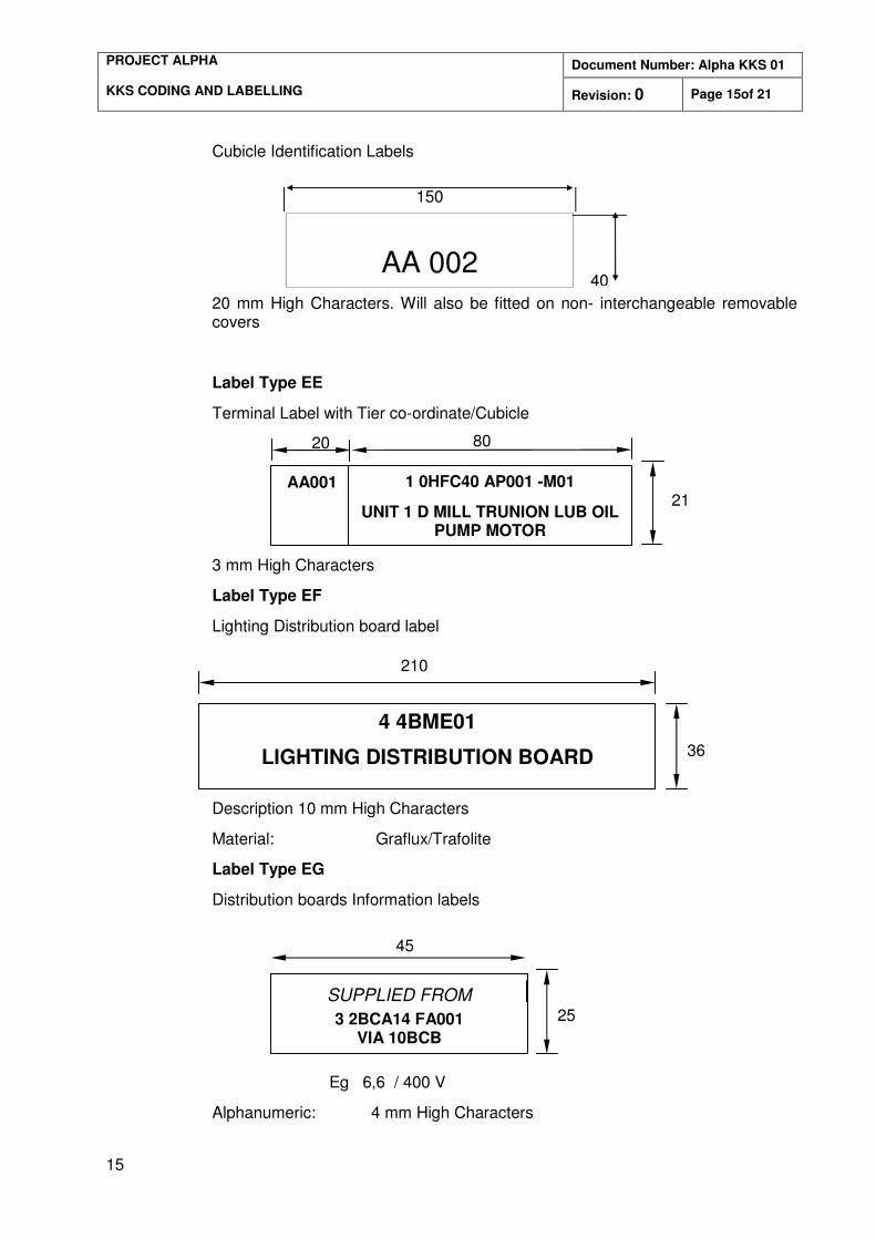
Cubicle Identification Labels
20 mm High Characters. Will also be fitted on non- interchangeable removable covers
Label Type EE
Terminal Label with Tier co-ordinate/Cubicle
(a) (b)
3 mm High Characters
Label Type EF
Lighting Distribution board label
Alphanumeric 10 mm High Characters
Description 10 mm High Characters
Material: Graflux/Trafolite
Label Type EG
Distribution boards Information labels
Eg 6,6 / 400 V
Alphanumeric: 4 mm High Characters
AA 002
150
40
80
21
20
AA001 1 0HFC40 AP001 -M01
UNIT 1 D MILL TRUNION LUB OIL PUMP MOTOR
4 4BME01
LIGHTING DISTRIBUTION BOARD
210
36
45
SUPPLIED FROM
3 2BCA14 FA001 VIA 10BCB
25
Document Number: Alpha KKS 01 PROJECT ALPHA KKS CODING AND LABELLING Revision: 0 Page 16of 21
16
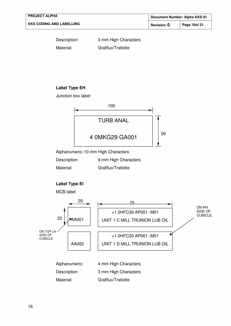
Description: 3 mm High Characters
Material: Grafflux/Trafolite
Label Type EH
Junction box label
Alphanumeric: 10 mm High Characters
Description: 9 mm High Characters
Material: Grafflux/Trafolite
Label Type EI
MCB label
A
(a) (b)
Alphanumeric: 4 mm High Characters
Description: 3 mm High Characters
Material: Grafflux/Trafolite
TURB ANAL
4 0MKG29 GA001
100
50
75 20
20
=1 0HFC30 AP001 -M01
UNIT 1 C MILL TRUNION LUB OIL
AA001
AA002
=1 0HFC20 AP001 -M01
UNIT 1 D MILL TRUNION LUB OIL
ON TOP LH SIDE OF CUBICLE
ON RH SIDE OF CUBICLE
Document Number: Alpha KKS 01 PROJECT ALPHA KKS CODING AND LABELLING Revision: 0 Page 17of 21
17
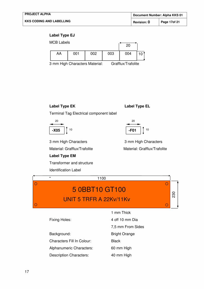
Label Type EJ
MCB Labels
3 mm High Characters Material: Grafflux/Trafolite
Label Type EK Label Type EL
Terminal Tag Electrical component label
3 mm High Characters 3 mm High Characters
Material: Grafflux/Trafolite Material: Grafflux/Trafolite
Label Type EM
Transformer and structure
Identification Label
-
-
-
Material: Cromadek
1 mm Thick
Fixing Holes: 4 off 10 mm Dia
7,5 mm From Sides
Background: Bright Orange
Characters Fill In Colour: Black
Alphanumeric Characters: 60 mm High
Description Characters: 40 mm High
AA 002
003 004 001
20
10
10 -X05
20 20
-F01 10
230
1100
5 0BBT10 GT100
UNIT 5 TRFR A 22Kv/11Kv
Document Number: Alpha KKS 01 PROJECT ALPHA KKS CODING AND LABELLING Revision: 0 Page 18of 21
18
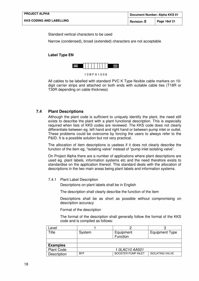
Standard vertical characters to be used
Narrow (condensed), broad (extended) characters are not acceptable
Label Type EN
1 0 B F A 1 0 0 8
All cables to be labelled with standard PVC K Type flexible cable markers on 10-digit carrier strips and attached on both ends with suitable cable ties (T18R or T30R depending on cable thickness)
7.4 Plant Descriptions
Although the plant code is sufficient to uniquely identify the plant, the need still exists to describe the plant with a plant functional description. This is especially required when lists of KKS codes are reviewed. The KKS code does not clearly differentiate between eg. left hand and right hand or between pump inlet or outlet. These problems could be overcome by forcing the users to always refer to the P&ID. It is a possible solution but not very practical.
The allocation of item descriptions is useless if it does not clearly describe the function of the item eg, “isolating valve” instead of “pump inlet isolating valve”.
On Project Alpha there are a number of applications where plant descriptions are used eg. plant labels, information systems etc and the need therefore exists to standardise on the application thereof. This standard deals with the allocation of descriptions in the two main areas being plant labels and information systems.
7.4.1 Plant Label Description
Descriptions on plant labels shall be in English
The description shall clearly describe the function of the item
Descriptions shall be as short as possible without compromising on description accuracy
Format of the description
The format of the description shall generally follow the format of the KKS code and is compiled as follows:
Level 1 2 3 Title System Equipment
Function Equipment Type
Examples Plant Code 1 0LAC10 AA501 Description BFP BOOSTER PUMP INLET ISOLATING VALVE
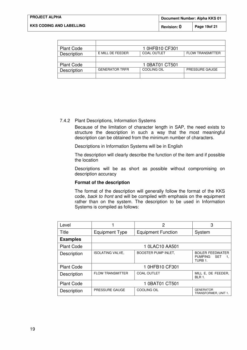
Document Number: Alpha KKS 01 PROJECT ALPHA KKS CODING AND LABELLING Revision: 0 Page 19of 21
19
Plant Code 1 0HFB10 CF301 Description E MILL DE FEEDER COAL OUTLET FLOW TRANSMITTER
Plant Code 1 0BAT01 CT501 Description GENERATOR TRFR COOLING OIL PRESSURE GAUGE
7.4.2 Plant Descriptions, Information Systems
Because of the limitation of character length in SAP, the need exists to structure the description in such a way that the most meaningful description can be obtained from the minimum number of characters.
Descriptions in Information Systems will be in English
The description will clearly describe the function of the item and if possible the location
Descriptions will be as short as possible without compromising on description accuracy
Format of the description
The format of the description will generally follow the format of the KKS code, back to front and will be compiled with emphasis on the equipment rather than on the system. The description to be used in Information Systems is compiled as follows:
Level 1 2 3
Title Equipment Type Equipment Function System
Examples
Plant Code 1 0LAC10 AA501
Description ISOLATING VALVE, BOOSTER PUMP INLET, BOILER FEEDWATER PUMPING SET 1, TURB 1.
Plant Code 1 0HFB10 CF301
Description FLOW TRANSMITTER COAL OUTLET MILL E, DE FEEDER, BLR 1.
Plant Code 1 0BAT01 CT501
Description PRESSURE GAUGE COOLING OIL GENERATOR TRANSFORMER, UNIT 1.
Document Number: Alpha KKS 01 PROJECT ALPHA KKS CODING AND LABELLING Revision: 0 Page 20of 21
20
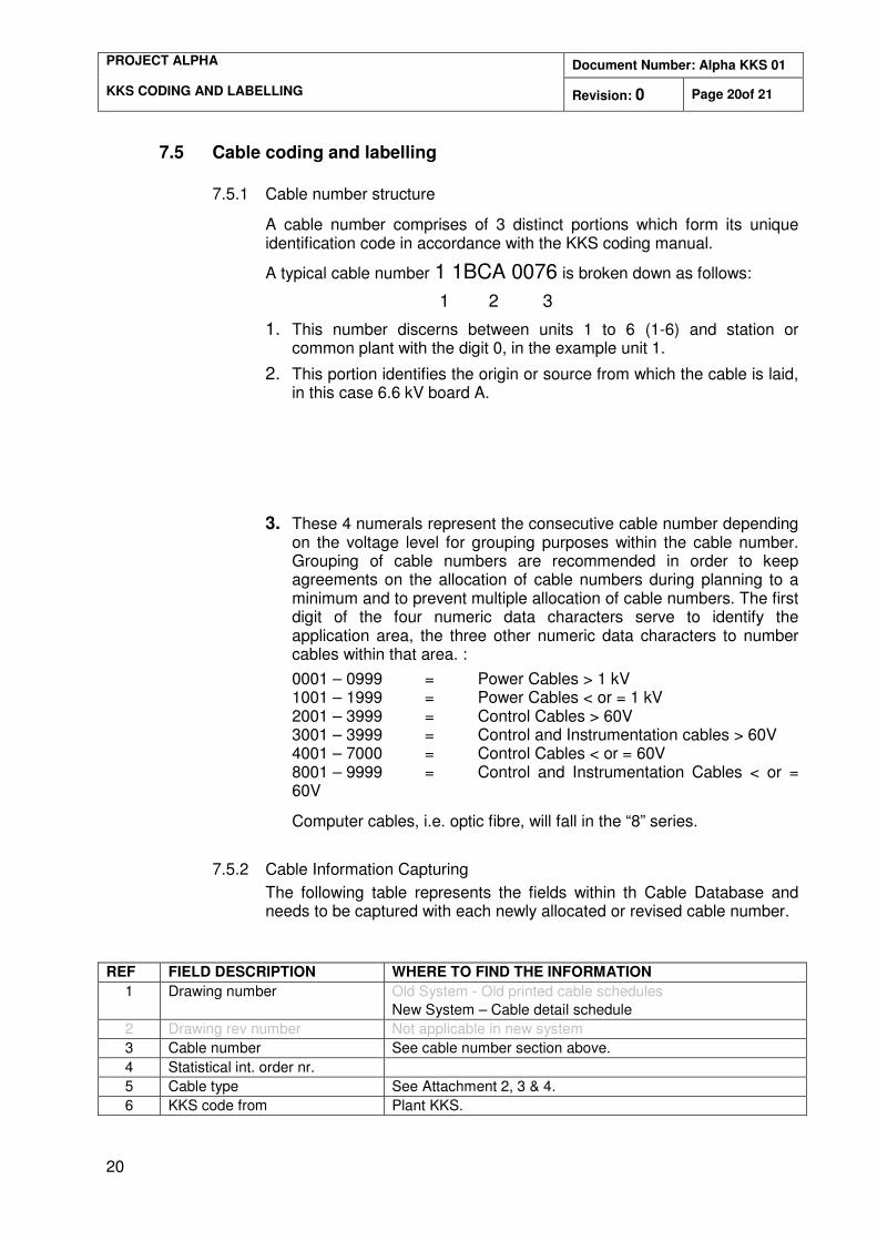
7.5 Cable coding and labelling
7.5.1 Cable number structure
A cable number comprises of 3 distinct portions which form its unique identification code in accordance with the KKS coding manual.
A typical cable number 1 1BCA 0076 is broken down as follows:
1 2 3
1. This number discerns between units 1 to 6 (1-6) and station or common plant with the digit 0, in the example unit 1.
2. This portion identifies the origin or source from which the cable is laid, in this case 6.6 kV board A.
3. These 4 numerals represent the consecutive cable number depending on the voltage level for grouping purposes within the cable number. Grouping of cable numbers are recommended in order to keep agreements on the allocation of cable numbers during planning to a minimum and to prevent multiple allocation of cable numbers. The first digit of the four numeric data characters serve to identify the application area, the three other numeric data characters to number cables within that area. :
0001 – 0999 = Power Cables > 1 kV 1001 – 1999 = Power Cables < or = 1 kV 2001 – 3999 = Control Cables > 60V 3001 – 3999 = Control and Instrumentation cables > 60V 4001 – 7000 = Control Cables < or = 60V 8001 – 9999 = Control and Instrumentation Cables < or = 60V
Computer cables, i.e. optic fibre, will fall in the “8” series.
7.5.2 Cable Information Capturing
The following table represents the fields within th Cable Database and needs to be captured with each newly allocated or revised cable number.
REF FIELD DESCRIPTION WHERE TO FIND THE INFORMATION
1 Drawing number
Old System - Old printed cable schedules
New System – Cable detail schedule
2 Drawing rev number Not applicable in new system
3 Cable number See cable number section above.
4 Statistical int. order nr.
5 Cable type See Attachment 2, 3 & 4.
6 KKS code from Plant KKS.
Document Number: Alpha KKS 01 PROJECT ALPHA KKS CODING AND LABELLING Revision: 0 Page 21of 21
21
7 KKS code to Plant KKS.
8 Cable rev type See Attachment 5.
9 Cable rev number The next sequential number.
10 Contractor identification See Attachment 6. (Applicable during construction period)
11 Remarks Any additional information.
12 Description from Plant description