Embed Size (px)
Citation preview

Questions
Question 1
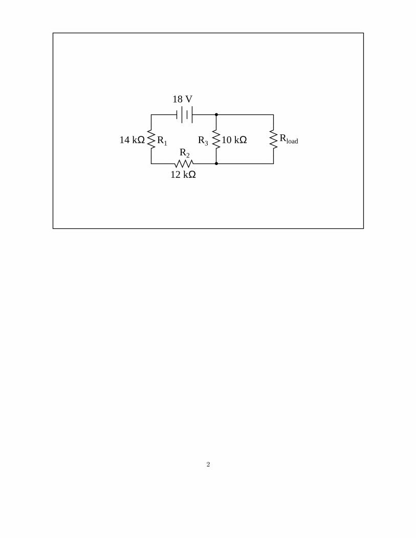
Animation: Applying Thevenin’s theorem
This question consists of a series of images (one per page) that form an animation. Flip the pages withyour fingers to view this animation (or click on the ”next” button on your viewer) frame-by-frame.
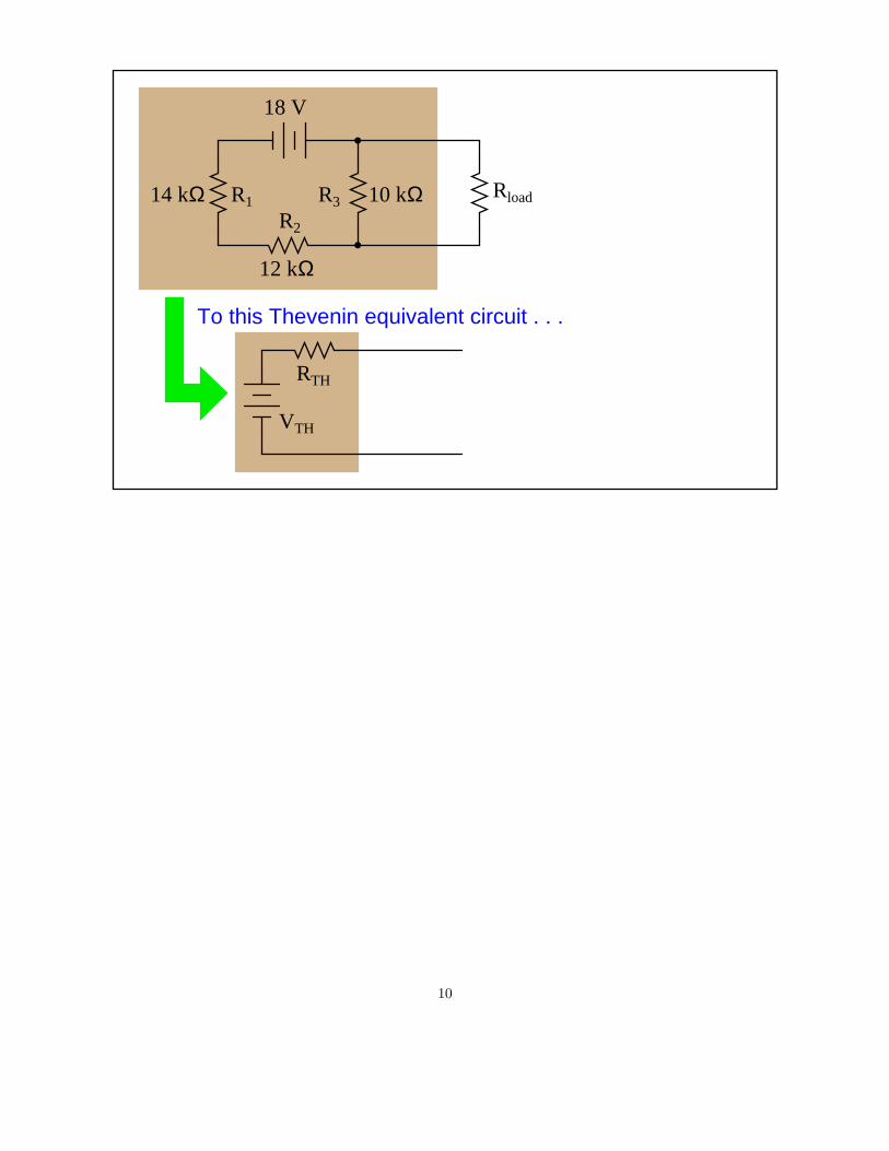
The following animation shows the steps involved in ”Thevenizing” a circuit.
1
RloadR1
R2
R3
18 V
10 kΩ
12 kΩ
14 kΩ
2
RloadR1
R2
R3
18 V
10 kΩ
12 kΩ
14 kΩ
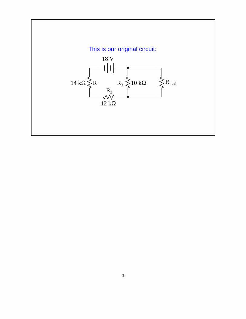
This is our original circuit:
3
RloadR1
R2
R3
18 V
10 kΩ
12 kΩ
14 kΩ
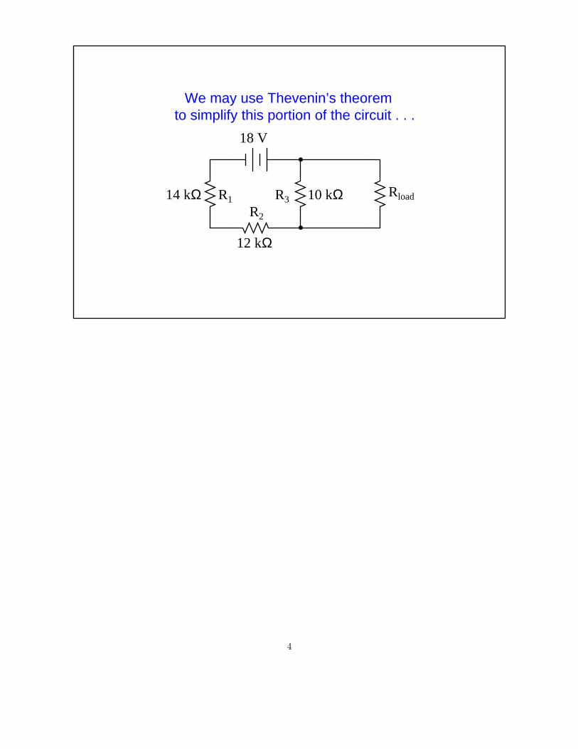
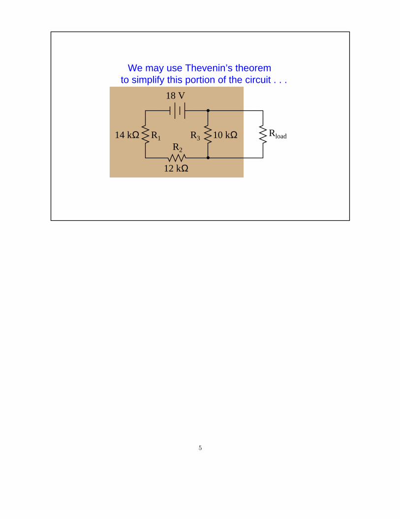
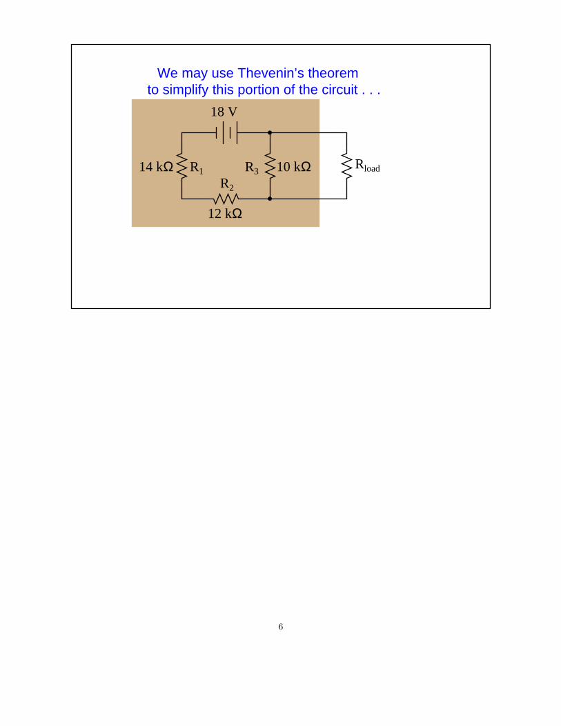
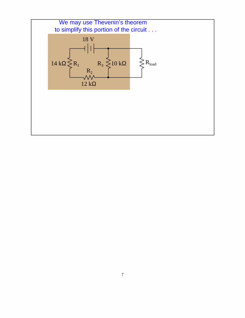
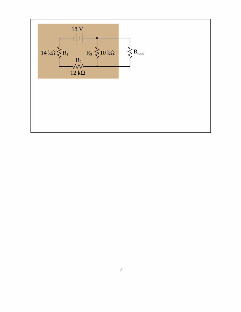
We may use Thevenin’s theoremto simplify this portion of the circuit . . .
4
Rload
We may use Thevenin’s theoremto simplify this portion of the circuit . . .
R1
R2
R3
18 V
10 kΩ
12 kΩ
14 kΩ
5
Rload
We may use Thevenin’s theoremto simplify this portion of the circuit . . .
R1
R2
R3
18 V
10 kΩ
12 kΩ
14 kΩ
6
Rload
We may use Thevenin’s theoremto simplify this portion of the circuit . . .
R1
R2
R3
18 V
10 kΩ
12 kΩ
14 kΩ
7
RloadR1
R2
R3
18 V
10 kΩ
12 kΩ
14 kΩ
8
RloadR1
R2
R3
18 V
10 kΩ
12 kΩ
14 kΩ
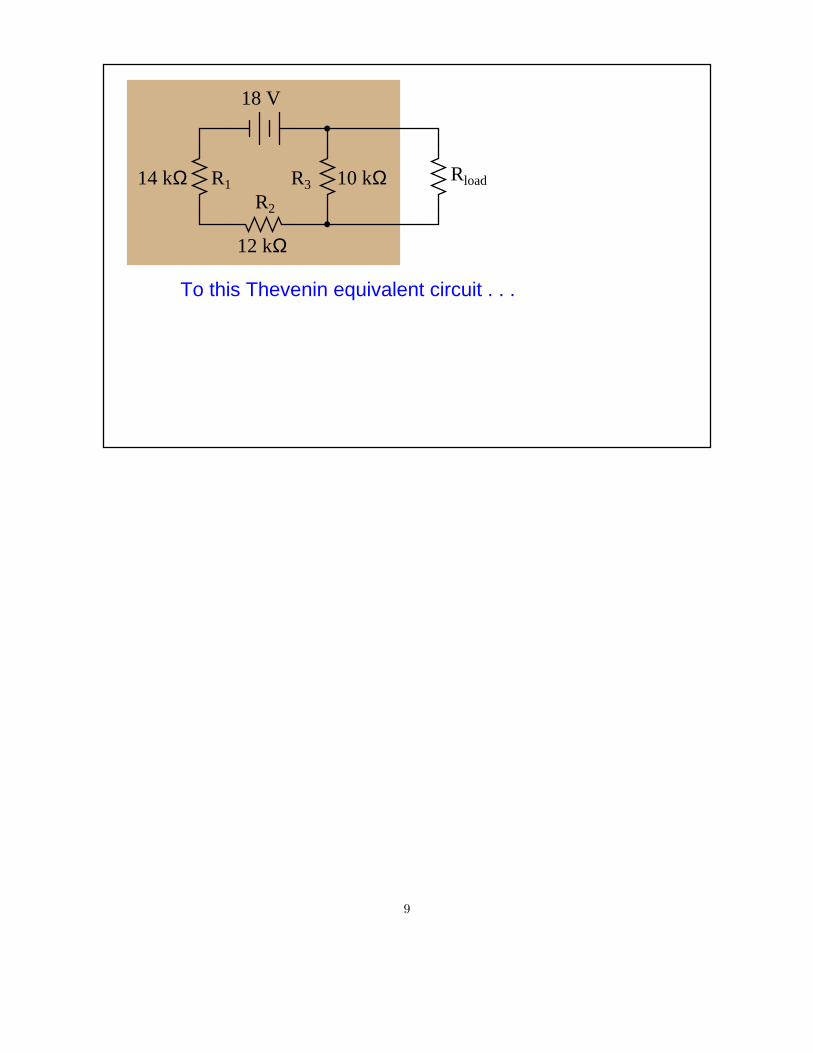
To this Thevenin equivalent circuit . . .
9
RloadR1
R2
R3
18 V
10 kΩ
12 kΩ
14 kΩ
To this Thevenin equivalent circuit . . .
VTH
RTH
10
RloadR1
R2
R3
18 V
10 kΩ
12 kΩ
14 kΩ
VTH
RTH
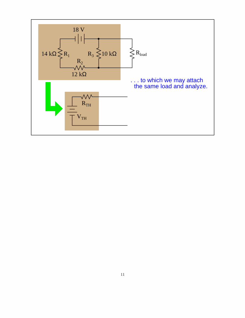
. . . to which we may attachthe same load and analyze.
11

RloadR1
R2
R3
18 V
10 kΩ
12 kΩ
14 kΩ
VTH
RTH
. . . to which we may attachthe same load and analyze.
Rload
12
RloadR1
R2
R3
18 V
10 kΩ
12 kΩ
14 kΩ
VTH
RTH
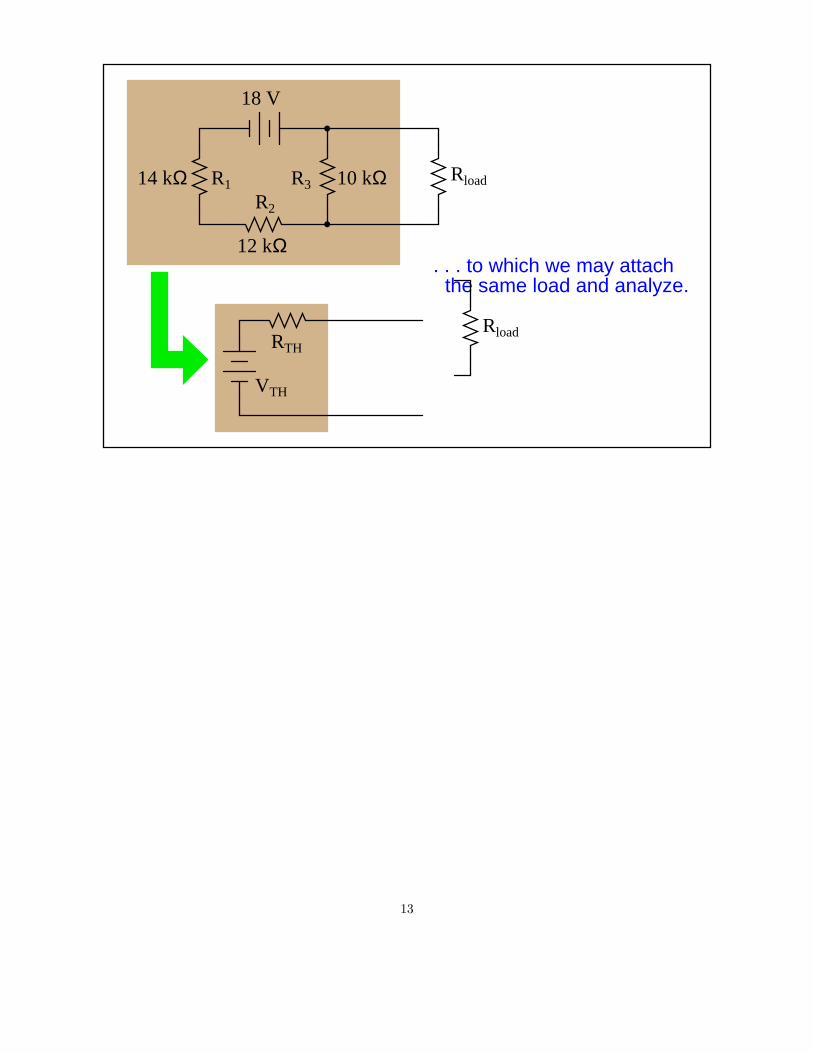
. . . to which we may attachthe same load and analyze.
Rload
13
RloadR1
R2
R3
18 V
10 kΩ
12 kΩ
14 kΩ
VTH
RTH
. . . to which we may attachthe same load and analyze.
Rload
14

RloadR1
R2
R3
18 V
10 kΩ
12 kΩ
14 kΩ
VTH
RTH
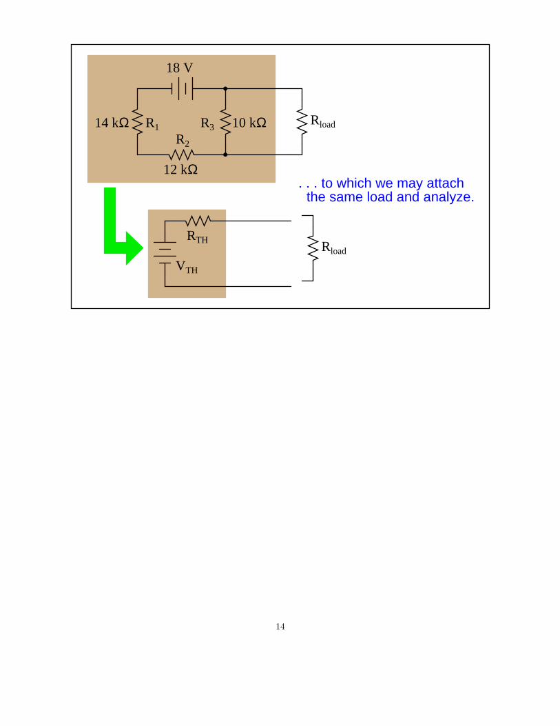
. . . to which we may attachthe same load and analyze.
Rload
15

RloadR1
R2
R3
18 V
10 kΩ
12 kΩ
14 kΩ
VTH
RTH
Rload
16

RloadR1
R2
R3
18 V
10 kΩ
12 kΩ
14 kΩ
VTH
RTH
Rload
the load resistor.First we disconnect
17

RloadR1
R2
R3
18 V
10 kΩ
12 kΩ
14 kΩ
VTH
RTH
the load resistor.First we disconnect
18

Rload
R1
R2
R3
18 V
10 kΩ
12 kΩ
14 kΩ
VTH
RTH
the load resistor.First we disconnect
19

Rload
R1
R2
R3
18 V
10 kΩ
12 kΩ
14 kΩ
VTH
RTH
the load resistor.First we disconnect
20

Rload
R1
R2
R3
18 V
10 kΩ
12 kΩ
14 kΩ
VTH
RTH
21

Rload
R1
R2
R3
18 V
10 kΩ
12 kΩ
14 kΩ
VTH
RTH
Then we calculate howmuch voltage appearsacross the open load
terminals.
22

Rload
R1
R2
R3
18 V
10 kΩ
12 kΩ
14 kΩ
VTH
RTH
Then we calculate howmuch voltage appearsacross the open load
terminals.+
V-
23

Rload
R1
R2
R3
18 V
10 kΩ
12 kΩ
14 kΩ
VTH
RTH
Then we calculate howmuch voltage appearsacross the open load
terminals.+
V-
24

Rload
R1
R2
R3
18 V
10 kΩ
12 kΩ
14 kΩ
VTH
RTH
Then we calculate howmuch voltage appearsacross the open load
terminals.+
V- (18 volts)
10 kΩ
(14 kΩ + 12 kΩ + 10 kΩ)
25

Rload
R1
R2
R3
18 V
10 kΩ
12 kΩ
14 kΩ
VTH
RTH
Then we calculate howmuch voltage appearsacross the open load
terminals.+
V- (18 volts)
10 kΩ
(14 kΩ + 12 kΩ + 10 kΩ)
= 5 volts
26

Rload
R1
R2
R3
18 V
10 kΩ
12 kΩ
14 kΩ
VTH
RTH
+V
-5 V
27

Rload
R1
R2
R3
18 V
10 kΩ
12 kΩ
14 kΩ
VTH
RTH
+V
-5 V
This voltage becomesour Thevenin sourcevoltage . . .
28

Rload
R1
R2
R3
18 V
10 kΩ
12 kΩ
14 kΩ
RTH
+V
-5 V
This voltage becomesour Thevenin sourcevoltage . . .
5 V
29

Rload
R1
R2
R3
18 V
10 kΩ
12 kΩ
14 kΩ
RTH
+V
-5 V
This voltage becomesour Thevenin sourcevoltage . . .
5 V. . . in the Thevenin equivalent circuit.
30

Rload
R1
R2
R3
18 V
10 kΩ
12 kΩ
14 kΩ
RTH
5 V
31

Rload
R1
R2
R3
18 V
10 kΩ
12 kΩ
14 kΩ
RTH
5 V
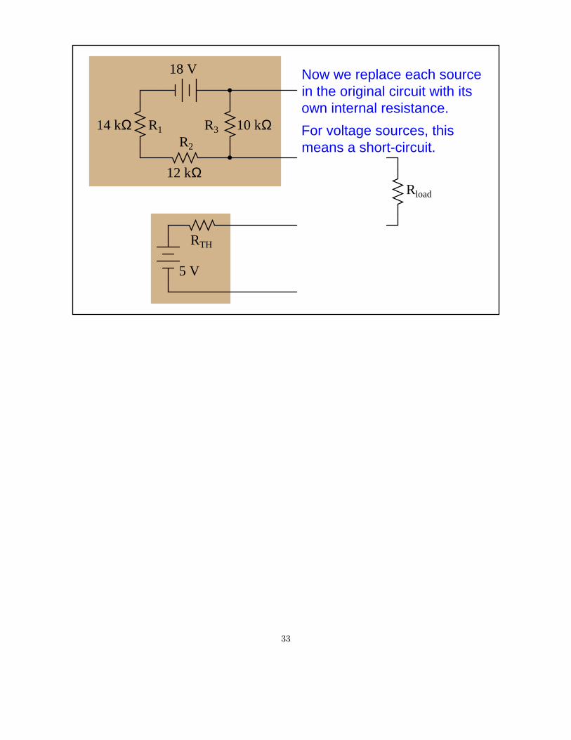
Now we replace each sourcein the original circuit with itsown internal resistance.
32
Rload
R1
R2
R3
18 V
10 kΩ
12 kΩ
14 kΩ
RTH
5 V
Now we replace each sourcein the original circuit with itsown internal resistance.
For voltage sources, thismeans a short-circuit.
33

Rload
R1
R2
R3
18 V
10 kΩ
12 kΩ
14 kΩ
RTH
5 V
Now we replace each sourcein the original circuit with itsown internal resistance.
For voltage sources, thismeans a short-circuit.
34

Rload
R1
R2
R3
18 V
10 kΩ
12 kΩ
14 kΩ
RTH
5 V
Now we replace each sourcein the original circuit with itsown internal resistance.
For voltage sources, thismeans a short-circuit.
35

Rload
R1
R2
R3 10 kΩ
12 kΩ
14 kΩ
RTH
5 V
Now we replace each sourcein the original circuit with itsown internal resistance.
For voltage sources, thismeans a short-circuit.
36

Rload
R1
R2
R3 10 kΩ
12 kΩ
14 kΩ
RTH
5 V
37

Rload
R1
R2
R3 10 kΩ
12 kΩ
14 kΩ
RTH
5 V
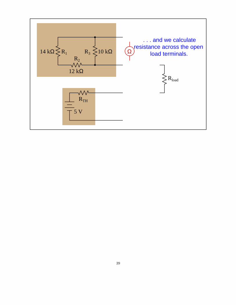
resistance across the openload terminals.
. . . and we calculate
38
Rload
R1
R2
R3 10 kΩ
12 kΩ
14 kΩ
RTH
5 V
resistance across the openload terminals.Ω
. . . and we calculate
39

Rload
R1
R2
R3 10 kΩ
12 kΩ
14 kΩ
RTH
5 V
resistance across the openload terminals.Ω
. . . and we calculate
40

Rload
R1
R2
R3 10 kΩ
12 kΩ
14 kΩ
RTH
5 V
resistance across the openload terminals.Ω
. . . and we calculate
(14 kΩ + 12 kΩ) // 10 kΩ
41

Rload
R1
R2
R3 10 kΩ
12 kΩ
14 kΩ
RTH
5 V
resistance across the openload terminals.Ω
. . . and we calculate
(14 kΩ + 12 kΩ) // 10 kΩ= 7.22 kΩ
42

Rload
R1
R2
R3 10 kΩ
12 kΩ
14 kΩ
RTH
5 V
Ω 7.22 kΩ
43

Rload
R1
R2
R3 10 kΩ
12 kΩ
14 kΩ
RTH
5 V
Ω 7.22 kΩ
This resistance becomesour Thevenin source
resistance . . .
44

Rload
R1
R2
R3 10 kΩ
12 kΩ
14 kΩ
5 V
Ω 7.22 kΩ
This resistance becomesour Thevenin source
resistance . . .
7.22 kΩ
45

Rload
R1
R2
R3 10 kΩ
12 kΩ
14 kΩ
5 V
Ω 7.22 kΩ
This resistance becomesour Thevenin source
resistance . . .
7.22 kΩ
. . . in the Thevenin equivalent circuit.
46

Rload
R1
R2
R3 10 kΩ
12 kΩ
14 kΩ
5 V
7.22 kΩ
18 V
47

Rload
R1
R2
R3 10 kΩ
12 kΩ
14 kΩ
5 V
7.22 kΩ
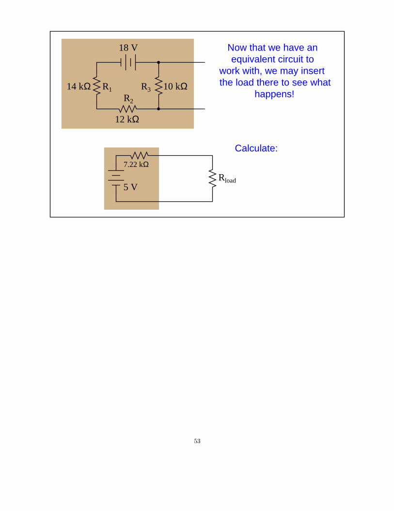
Now that we have an equivalent circuit to
work with, we may insertthe load there to see what
happens!
18 V
48

Rload
R1
R2
R3 10 kΩ
12 kΩ
14 kΩ
5 V
7.22 kΩ
Now that we have an equivalent circuit to
work with, we may insertthe load there to see what
happens!
18 V
49

Rload
R1
R2
R3 10 kΩ
12 kΩ
14 kΩ
5 V
7.22 kΩ
Now that we have an equivalent circuit to
work with, we may insertthe load there to see what
happens!
18 V
50

Rload
R1
R2
R3 10 kΩ
12 kΩ
14 kΩ
5 V
7.22 kΩ
Now that we have an equivalent circuit to
work with, we may insertthe load there to see what
happens!
18 V
51

Rload
R1
R2
R3 10 kΩ
12 kΩ
14 kΩ
5 V
7.22 kΩ
Now that we have an equivalent circuit to
work with, we may insertthe load there to see what
happens!
18 V
52
Rload
R1
R2
R3 10 kΩ
12 kΩ
14 kΩ
5 V
7.22 kΩ
Now that we have an equivalent circuit to
work with, we may insertthe load there to see what
happens!
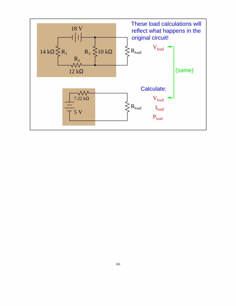
Calculate:
18 V
53

Rload
R1
R2
R3 10 kΩ
12 kΩ
14 kΩ
5 V
7.22 kΩ
Now that we have an equivalent circuit to
work with, we may insertthe load there to see what
happens!
Calculate:
Vload
18 V
54

Rload
R1
R2
R3 10 kΩ
12 kΩ
14 kΩ
5 V
7.22 kΩ
Now that we have an equivalent circuit to
work with, we may insertthe load there to see what
happens!
Calculate:
Vload
Iload
18 V
55

Rload
R1
R2
R3 10 kΩ
12 kΩ
14 kΩ
5 V
7.22 kΩ
Now that we have an equivalent circuit to
work with, we may insertthe load there to see what
happens!
Calculate:
Vload
Iload
Pload
18 V
56

Rload
R1
R2
R3 10 kΩ
12 kΩ
14 kΩ
5 V
7.22 kΩ
Calculate:
Vload
Iload
Pload
18 V
57

Rload
R1
R2
R3 10 kΩ
12 kΩ
14 kΩ
5 V
7.22 kΩ
Calculate:
Vload
Iload
Pload
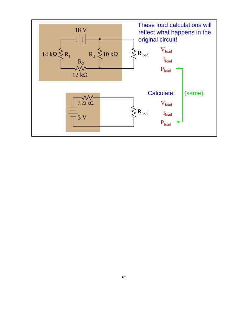
18 VThese load calculations willreflect what happens in theoriginal circuit!
58

Rload
R1
R2
R3 10 kΩ
12 kΩ
14 kΩ
5 V
7.22 kΩ
Calculate:
Vload
Iload
Pload
18 VThese load calculations willreflect what happens in theoriginal circuit!
Rload
59
Rload
R1
R2
R3 10 kΩ
12 kΩ
14 kΩ
5 V
7.22 kΩ
Calculate:
Vload
Iload
Pload
18 VThese load calculations willreflect what happens in theoriginal circuit!
RloadVload
(same)
60

Rload
R1
R2
R3 10 kΩ
12 kΩ
14 kΩ
5 V
7.22 kΩ
Calculate:
Vload
Iload
Pload
18 VThese load calculations willreflect what happens in theoriginal circuit!
RloadVload
(same)
Iload
61
Rload
R1
R2
R3 10 kΩ
12 kΩ
14 kΩ
5 V
7.22 kΩ
Calculate:
Vload
Iload
Pload
18 VThese load calculations willreflect what happens in theoriginal circuit!
RloadVload
(same)
Iload
Pload
62

Rload
R1
R2
R3 10 kΩ
12 kΩ
14 kΩ
5 V
7.22 kΩ
Calculate:
Vload
Iload
Pload
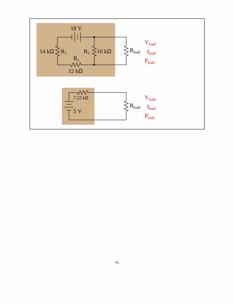
18 VThese load calculations willreflect what happens in theoriginal circuit!
RloadVload
Iload
Pload
63

Rload
R1
R2
R3 10 kΩ
12 kΩ
14 kΩ
5 V
7.22 kΩ Vload
Iload
Pload
18 V
Rload
Vload
Iload
Pload
64
Rload
R1
R2
R3 10 kΩ
12 kΩ
14 kΩ
5 V
7.22 kΩ Vload
Iload
Pload
18 V
Rload
Vload
Iload
Pload
65
Rload
R1
R2
R3 10 kΩ
12 kΩ
14 kΩ
5 V
7.22 kΩ Vload
Iload
Pload
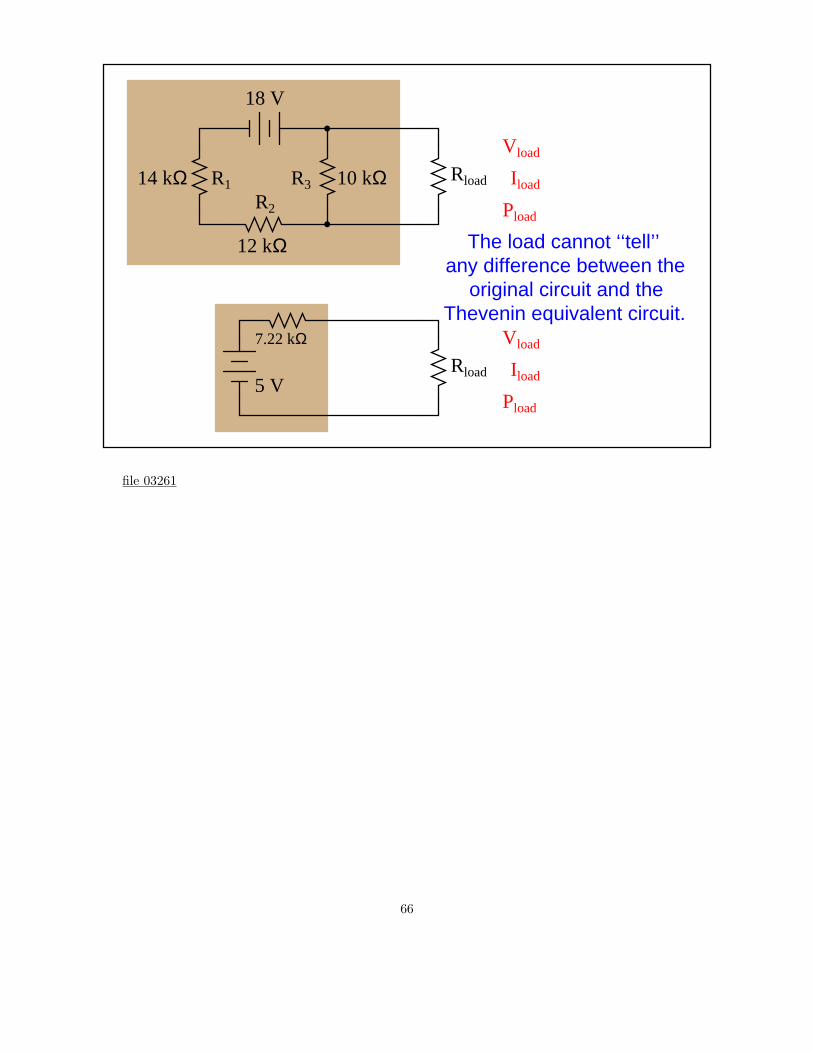
18 V
Rload
Vload
Iload
Pload
The load cannot ‘‘tell’’any difference between the
Thevenin equivalent circuit.original circuit and the
file 03261
66

Answers
Answer 1
Nothing to note here.
67

Notes
Notes 1
The purpose of this animation is to let students see how Thevenin’s theorem may be applied to the
simplification of a resistor network.
68