Embed Size (px)
Citation preview
October 2007 Appendix B 1
APPENDIX B — WORKSHEETS & EXHIBITS
Temporary Construction Ingress/Egress Pad Plan View ................ 5 Worksheet (Large Sites – Two Acres or Larger)
Temporary Construction Ingress/Egress Pad Cross-Section .......... 7 View Worksheet (Large Sites – Two Acres or Larger)
Temporary Construction Ingress/Egress Pad Plan View ................ 9 Worksheet (Small Sites – Less Than Two Acres)
Riprap Slope Protection Worksheet .............................................. 11
Temporary Diversion Worksheet .................................................. 13
Permanent Diversion Worksheet ................................................... 15
Perimeter Diversion Dike Worksheet ............................................ 17
Water Bar Worksheet .................................................................... 19
Rock Check Dam Worksheet ........................................................ 21
Temporary Slope Drain Worksheet ............................................... 23
Grass-Lined Channel Worksheet ................................................... 25
Riprap-Lined Channel Worksheet ................................................. 27
Energy Dissipater Worksheet 1 ..................................................... 29
Energy Dissipater Worksheet 2 ..................................................... 31
Concrete Block Chute Worksheet ................................................. 33
Excavated Drop Inlet Protection Worksheet ................................. 35
Temporary Sediment Trap Rock Dam Worksheet ........................ 37
Temporary Sediment Trap Outlet Worksheet ............................... 39
A worksheet provides the designer a representation of a measure that allows for input of specific design criteria. The plan designer will be required to assess field conditions and apply engineering principles to determine dimensions and specifications. An exhibit is a representa-tive view of a measure. An exhibit often includes standardized dimensions and specifications. Several exhibits are only a representative view of the measure, and will require the designer to assess field conditions and input dimensions and specifications for the measure. These exhibits have been identified with a note.
Worksheet Page

2 Appendix B October 2007
APPENDIX B — WORKSHEETS & EXHIBITS
Temporary Dry Sediment Basin Earthen Dam/ ............................ 41 Embankment Worksheet
Temporary Dry Sediment Basin Spillway Worksheet 1 ............... 43
Temporary Dry Sediment Basin Spillway Worksheet 2 ............... 45
Concrete Washout (Above Grade System) Worksheet ................. 47
Concrete Washout (Below Grade System) Worksheet ................. 49
Surface Roughening – Stair-Step Worksheet ............................... 51
Surface Roughening – Grooving Worksheet ................................ 53
Sod Exhibit 1 ................................................................................. 55
Perimeter Diversion Dike Exhibit 1 .............................................. 57
Water Bar Exhibit 1 ...................................................................... 59
Rock Check Dam Exhibit 1 .......................................................... 61
Rock Check Dam Exhibit 2 .......................................................... 63
Temporary Slope Drain Exhibit 1 ................................................. 65
Rock-Lined Chute Exhibit 1 ........................................................ 67 (requires inclusion of dimensions and specifications)
Reinforced Vegetated Chute Exhibit 1 ........................................ 69 (requires inclusion of dimensions and specifications)
Excavated Drop Inlet Protection Exhibit 1 ................................... 71
Gravel Donut Drop Inlet Protection Exhibit 1 .............................. 73
Gravel Donut Drop Inlet Protection Exhibit 2 .............................. 75
Geotextile Fabric Drop Inlet Protection Exhibit 1 ........................ 77
Geotextile Fabric Drop Inlet Protection Exhibit 2 ........................ 79
Worksheet Page
Exhibit Page

October 2007 Appendix B 3
APPENDIX B — WORKSHEETS & EXHIBITS
Straw Bale Drop Inlet Protection Exhibit 1 .................................. 81
Straw Bale Drop Inlet Protection Exhibit 2 .................................. 83
Block & Gravel Drop Inlet Protection Exhibit 1 .......................... 85
Block & Gravel Drop Inlet Protection Exhibit 2 .......................... 87
Stone Bag Curb Inlet Protection Exhibit 1 ................................... 89
Stone Bag Curb Inlet Protection Exhibit 2 ................................... 91
Block & Gravel Curb Inlet Protection Exhibit 1 .......................... 93
Block & Gravel Curb Inlet Protection Exhibit 2 .......................... 95
Temporary Dry Sediment Basin Riser Pipe Exhibit 1 .................. 97
Silt Fence Exhibit 1 ....................................................................... 99
Silt Fence Exhibit 2 ..................................................................... 101
Silt Fence Exhibit 3 ..................................................................... 103
Straw Bale Dam Exhibit 1 .......................................................... 105
Straw Bale Dam Exhibit 2 .......................................................... 107
Straw Bale Dam Exhibit 3 .......................................................... 109
Straw Bale Dam Exhibit 4 .......................................................... 111
Temporary Stream Crossing – Bridges Exhibit 1 ....................... 113 (requires inclusion of dimensions and specifications)
Temporary Stream Crossing – Culverts Exhibit 1 ...................... 115 (requires inclusion of dimensions and specifications)
Temporary Stream Crossing – Fords Exhibit 1 .......................... 117 (requires inclusion of dimensions and specifications)
Temporary Stream Crossing – Fords Exhibit 2 .......................... 119 (requires inclusion of dimensions and specifications)
Exhibit Page

This page was intentionally left blank.

October 2007 Appendix B 5
WORKSHEET
Temporary Construction Ingress/Egress Pad Plan View Worksheet
(large sites—two acres or larger)
T = _____ inches W = _____ feet
L = _____ feet
Public Road
Geotextile Fabric Underliner
INDOT CA No. 2 Aggregate
L = Ingress/Egress Pad Length W = Ingress/Egress Pad Width T = Aggregate Thickness (Note: For minimum dimensions, see the “Specifications” section of this measure.)
Top-Dress First 50 Feet Adjacent to Public Roadway with 2-3 Inches of INDOT CA No. 53 Aggregate (optional)
Source: Adapted from North Carolina Erosion and Sediment Control Planning and Design Manual, 1993
For information on this measure, see Chapter 7,
page 17

This page was intentionally left blank.

October 2007 Appendix B 7
WORKSHEET
Temporary Construction Ingress/Egress Pad Cross-Section View Worksheet (large sites two acres or larger)
H = _____ inches
Public Road
15 Feet Grade > 2%
Geotextile Fabric Underliner
Diversion Ridge with 3:1 Side Slopes
H = Height of Diversion Ridge (Note: 8 inches minimum)
Source: Adapted from North Carolina Erosion and Sediment Control Planning and Design Manual, 1993
For information on this measure, see Chapter 7,
page 17

This page was intentionally left blank.
October 2007 Appendix B 9
WORKSHEET
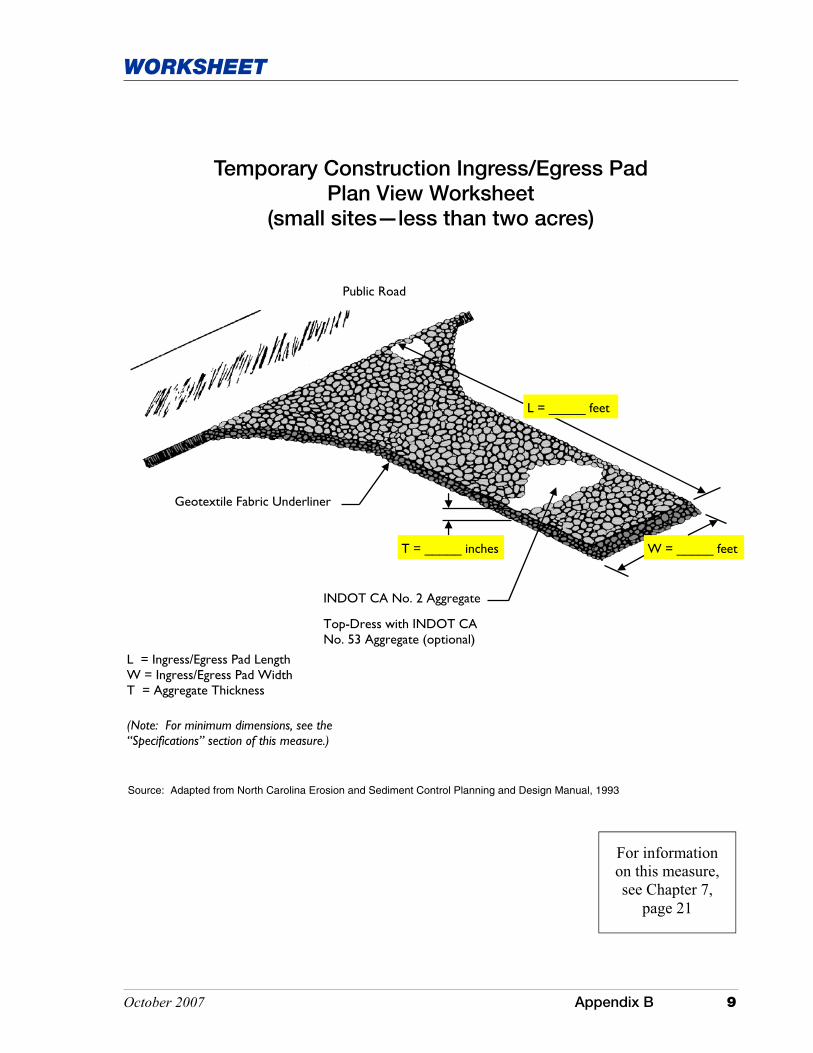
Temporary Construction Ingress/Egress Pad Plan View Worksheet
(small sites—less than two acres)
T = _____ inches W = _____ feet
L = _____ feet
Public Road
Geotextile Fabric Underliner
INDOT CA No. 2 Aggregate
L = Ingress/Egress Pad Length W = Ingress/Egress Pad Width T = Aggregate Thickness
(Note: For minimum dimensions, see the “Specifications” section of this measure.)
Top-Dress with INDOT CA No. 53 Aggregate (optional)
Source: Adapted from North Carolina Erosion and Sediment Control Planning and Design Manual, 1993
For information on this measure, see Chapter 7,
page 21

This page was intentionally left blank.

October 2007 Appendix B 11
WORKSHEET
Smooth foundation under bedding material/ filter medium
Bedding material/ filter medium
Keyway T = Aggregate Thickness (� 2 x d50)
T = _____ feet
1.5 T (min.)
T = ____ feet
Riprap Slope Protection Worksheet
Source: Adapted from North Carolina Erosion and Sediment Control Planning and Design Manual, 1993
For information on this measure, see Chapter 7,
page 69

This page was intentionally left blank.

October 2007 Appendix B 13
WORKSHEET
CD = Channel Depth
CW = Channel Width
RW = Ridge Width
Temporary Diversion Worksheet
For information on this measure, see Chapter 7,
page 75
Protected Area
6 inch freeboard
All constructed slopes 2:1 or flatter
Flow
CD = _____ feet
Allowance for 10% Settlement
CW = _____ feet RW = _____ feet

This page was intentionally left blank.
October 2007 Appendix B 15
WORKSHEET
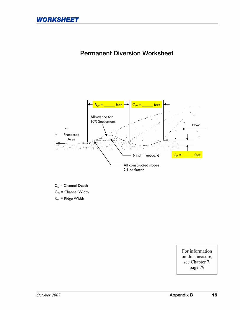
Permanent Diversion Worksheet
For information on this measure, see Chapter 7,
page 79
Protected Area
6 inch freeboard
All constructed slopes 2:1 or flatter
Flow
CD = _____ feet
CD = Channel Depth
CW = Channel Width
RW = Ridge Width
Allowance for 10% Settlement
CW = _____ feet RW = _____ feet

This page was intentionally left blank.

October 2007 Appendix B 17
WORKSHEET
Perimeter Diversion Dike Worksheet
For information on this measure, see Chapter 7,
page 83
6 inch freeboard
All constructed slopes 2:1 or flatter
RH = _____ inches
CW = _____ feet
Allowance for 10% settlement
Flow
CD = _____ inches
RH = Ridge Height
RW = Ridge Base Width
CD = Channel Depth
CW = Channel Top Width
Note: Drainage channel is optional.
Protected Area
RW = _____ feet

This page was intentionally left blank.
October 2007 Appendix B 19
WORKSHEET
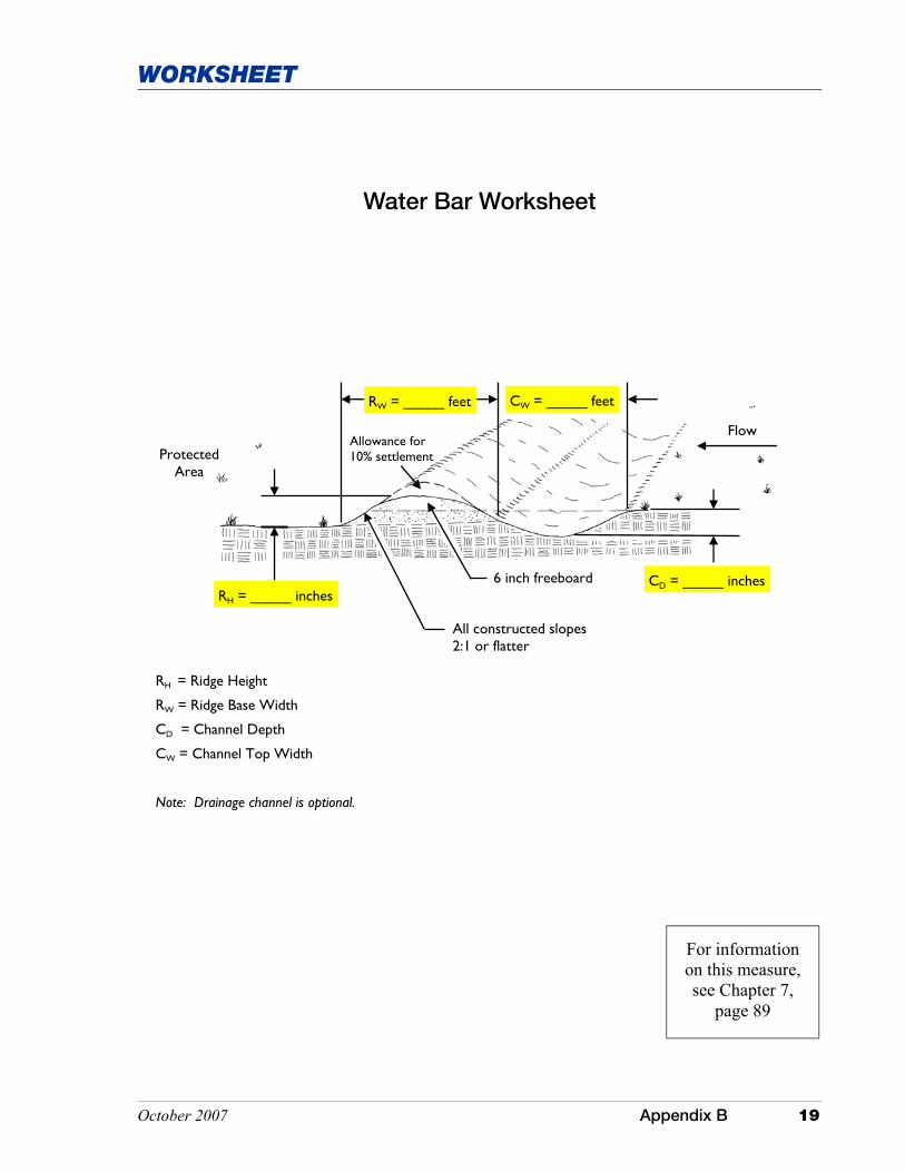
6 inch freeboard
All constructed slopes 2:1 or flatter
RH = _____ inches
CW = _____ feet
Allowance for 10% settlement
Flow
CD = _____ inches
RH = Ridge Height
RW = Ridge Base Width
CD = Channel Depth
CW = Channel Top Width
Note: Drainage channel is optional.
Protected Area
Water Bar Worksheet
For information on this measure, see Chapter 7,
page 89
RW = _____ feet

This page was intentionally left blank.
October 2007 Appendix B 21
WORKSHEET
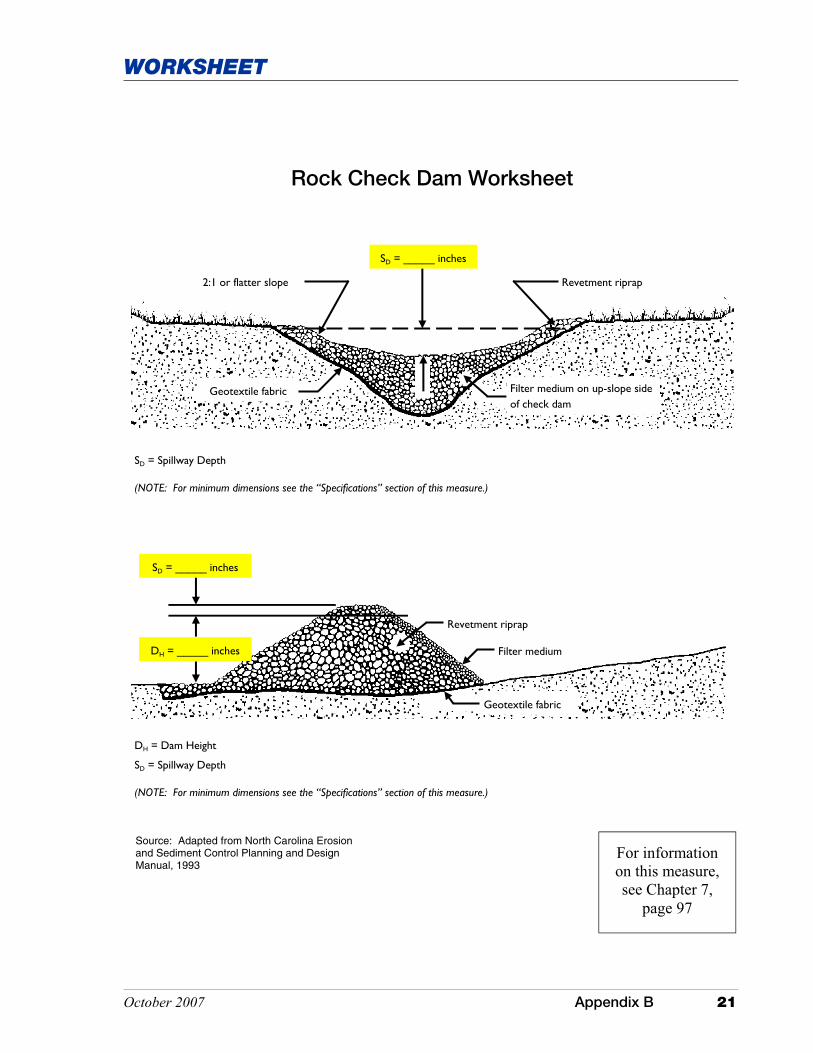
Rock Check Dam Worksheet
DH = Dam Height
SD = Spillway Depth
(NOTE: For minimum dimensions see the “Specifications” section of this measure.)
Revetment riprap
Filter medium
Geotextile fabric
DH = _____ inches
SD = _____ inches
Filter medium on up-slope side of check dam
Geotextile fabric
SD = _____ inches
Revetment riprap 2:1 or flatter slope
SD = Spillway Depth
(NOTE: For minimum dimensions see the “Specifications” section of this measure.)
Source: Adapted from North Carolina Erosion and Sediment Control Planning and Design Manual, 1993
For information on this measure, see Chapter 7,
page 97

This page was intentionally left blank.

October 2007 Appendix B 23
WORKSHEET
Temporary Slope Drain Worksheet
IBH = _____ feet
LSL = _____ feet
Stabilized outlet
PD = _____ inches
IBH = Island Berm Height
IBW = Island Berm Width
DBH = Diversion Berm Height
DBW = Diversion Berm Width
LSL = Level Section Length
TSS = Tie-Down Stake Spacing
PD = Pipe Diameter
(Note: For minimum and maximum dimensions, see the “Specifications” section of this measure.)
IBW = _____ feet
DBW = _____ feet
DBH = _____ feet
TSS = _____ feet
Source: Adapted from North Carolina Erosion and Sediment Control Planning and Design Manual, 1993
For information on this measure, see Chapter 7,
page 103

This page was intentionally left blank.
October 2007 Appendix B 25
WORKSHEET
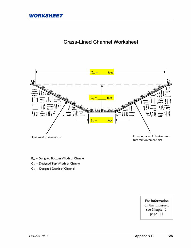
BW = _____ feet
CD = _____ feet
Erosion control blanket over turf reinforcement mat
Turf reinforcement mat
BW = Designed Bottom Width of Channel
CW = Designed Top Width of Channel
CD = Designed Depth of Channel
CW = _____ feet
Grass-Lined Channel Worksheet
For information on this measure, see Chapter 7,
page 111

This page was intentionally left blank.
October 2007 Appendix B 27
WORKSHEET
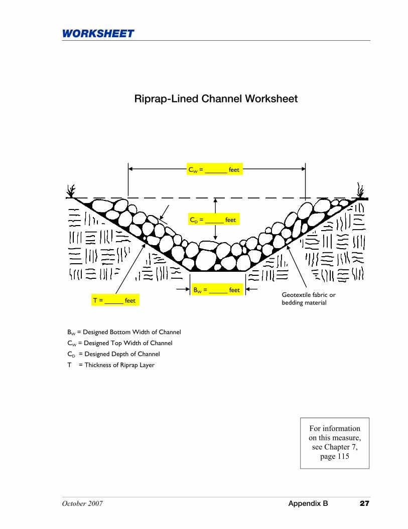
Riprap-Lined Channel Worksheet
For information on this measure, see Chapter 7,
page 115
Geotextile fabric or bedding material T = _____ feet
CD = _____ feet
BW = Designed Bottom Width of Channel
CW = Designed Top Width of Channel
CD = Designed Depth of Channel
T = Thickness of Riprap Layer
BW = _____ feet
CW = ______ feet

This page was intentionally left blank.

October 2007 Appendix B 29
WORKSHEET
AL = _____ feet
AT = _____ feet Geotextile fabric or well-graded aggregate
Check slot (optional)
Drain pipe with flared end section
Stable outlet
Top of apron level with receiving channel Plunge pool
(optional)
AL = Apron Length
AT = Apron Thickness
Energy Dissipater Worksheet 1
For information on this measure, see Chapter 7,
page 121

This page was intentionally left blank.

October 2007 Appendix B 31
WORKSHEET
AT = _____ feet
AW = _____ feet
Drain pipe Stone placed around end of drain pipe to prevent slope erosion and undercutting of the pipe
Stone apron below pipe discharge
Geotextile fabric or well graded aggregate
AT = Apron Thickness AW = Apron Width
Note: AW is the apron width at the narrow end of the apron.
Energy Dissipater Worksheet 2
For information on this measure, see Chapter 7,
page 121

This page was intentionally left blank.

October 2007 Appendix B 33
WORKSHEET
2:1 or flatter slope
Subsurface drain tile offset from center of channel to prevent seepage of up-slope groundwater
Plastic sheeting
Concrete blocks
BTW = Berm Top Width
Geotextile fabric
Bedding material
___:1 slope
BTW = _____ feet
___:1 slope
Concrete Block Chute Worksheet
Source: Adapted from U.S. Department of Agriculture, Natural Resources Conservation Service
For information on this measure, see Chapter 7,
page 131

This page was intentionally left blank.
October 2007 Appendix B 35
WORKSHEET
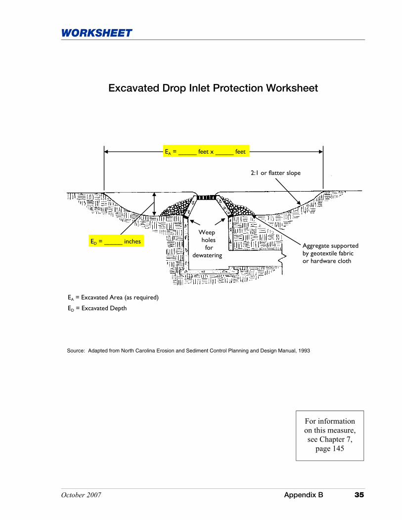
Excavated Drop Inlet Protection Worksheet
Source: Adapted from North Carolina Erosion and Sediment Control Planning and Design Manual, 1993
For information on this measure, see Chapter 7,
page 145
ED = _____ inches Weep holes for dewatering
Aggregate supported by geotextile fabric or hardware cloth
EA = Excavated Area (as required)
ED = Excavated Depth
2:1 or flatter slope
EA = _____ feet x _____ feet

This page was intentionally left blank.
October 2007 Appendix B 37
WORKSHEET
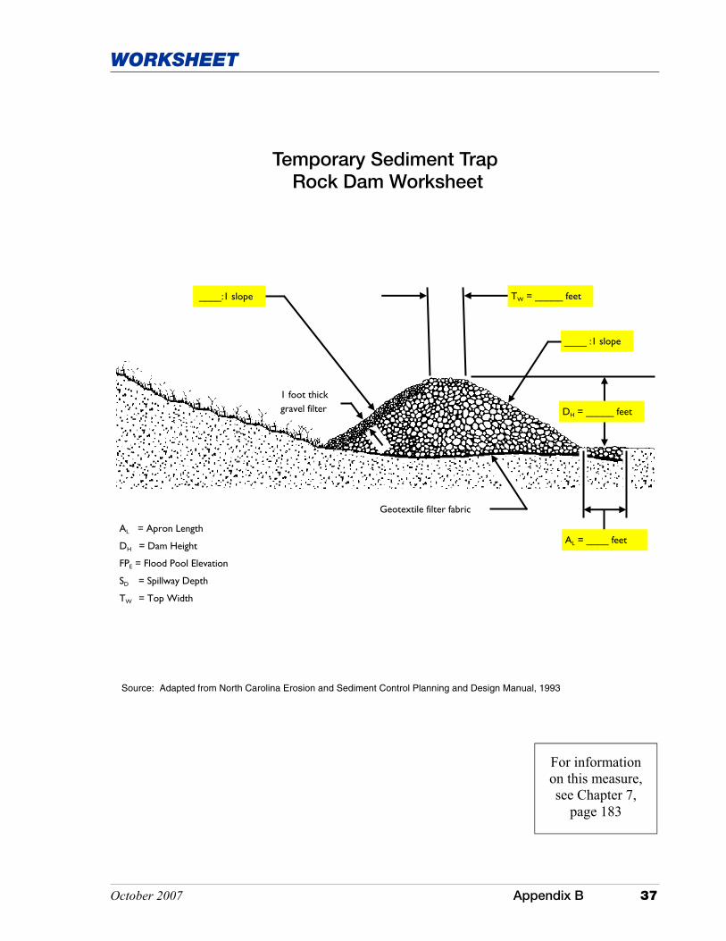
Temporary Sediment Trap Rock Dam Worksheet
Source: Adapted from North Carolina Erosion and Sediment Control Planning and Design Manual, 1993
SD = _____ feet FPE = _____ feet
AL = Apron Length
DH = Dam Height
FPE = Flood Pool Elevation
SD = Spillway Depth
TW = Top Width
Geotextile filter fabric
AL = ____ feet
DH = _____ feet
____ :1 slope
1 foot thick gravel filter
____:1 slope TW = _____ feet
For information on this measure, see Chapter 7,
page 183

This page was intentionally left blank.
October 2007 Appendix B 39
WORKSHEET
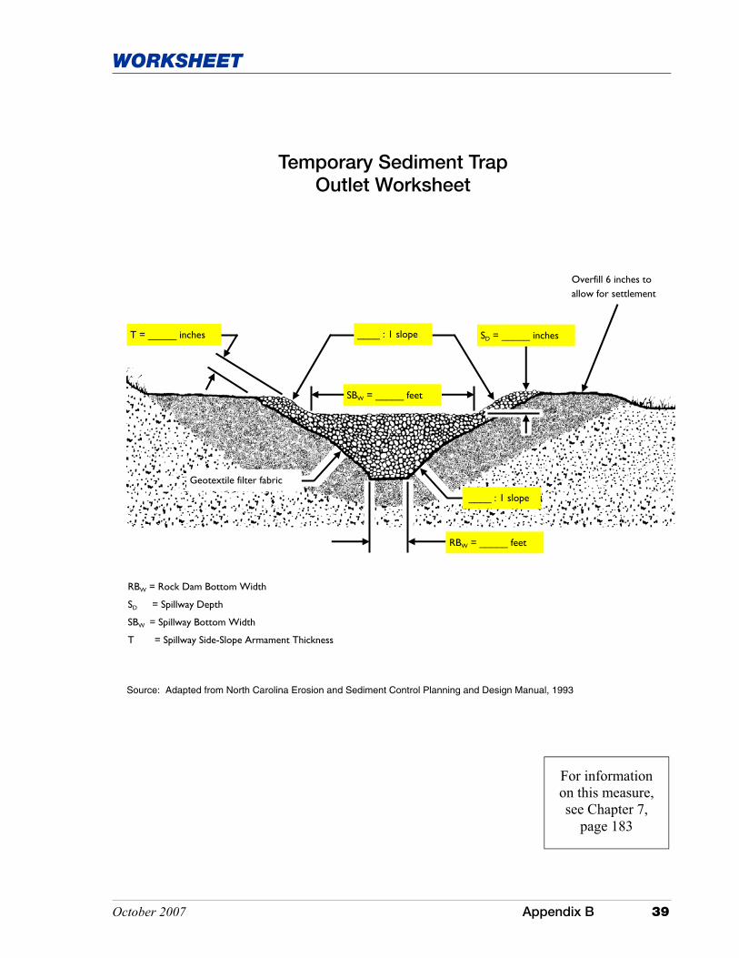
SBW = _____ feet
SD = _____ inches ____ : 1 slope
Overfill 6 inches to allow for settlement
____ : 1 slope
Geotextile filter fabric
T = _____ inches
RBW = _____ feet
RBW = Rock Dam Bottom Width
SD = Spillway Depth
SBW = Spillway Bottom Width
T = Spillway Side-Slope Armament Thickness
Temporary Sediment Trap Outlet Worksheet
Source: Adapted from North Carolina Erosion and Sediment Control Planning and Design Manual, 1993
For information on this measure, see Chapter 7,
page 183

This page was intentionally left blank.
October 2007 Appendix B 41
WORKSHEET
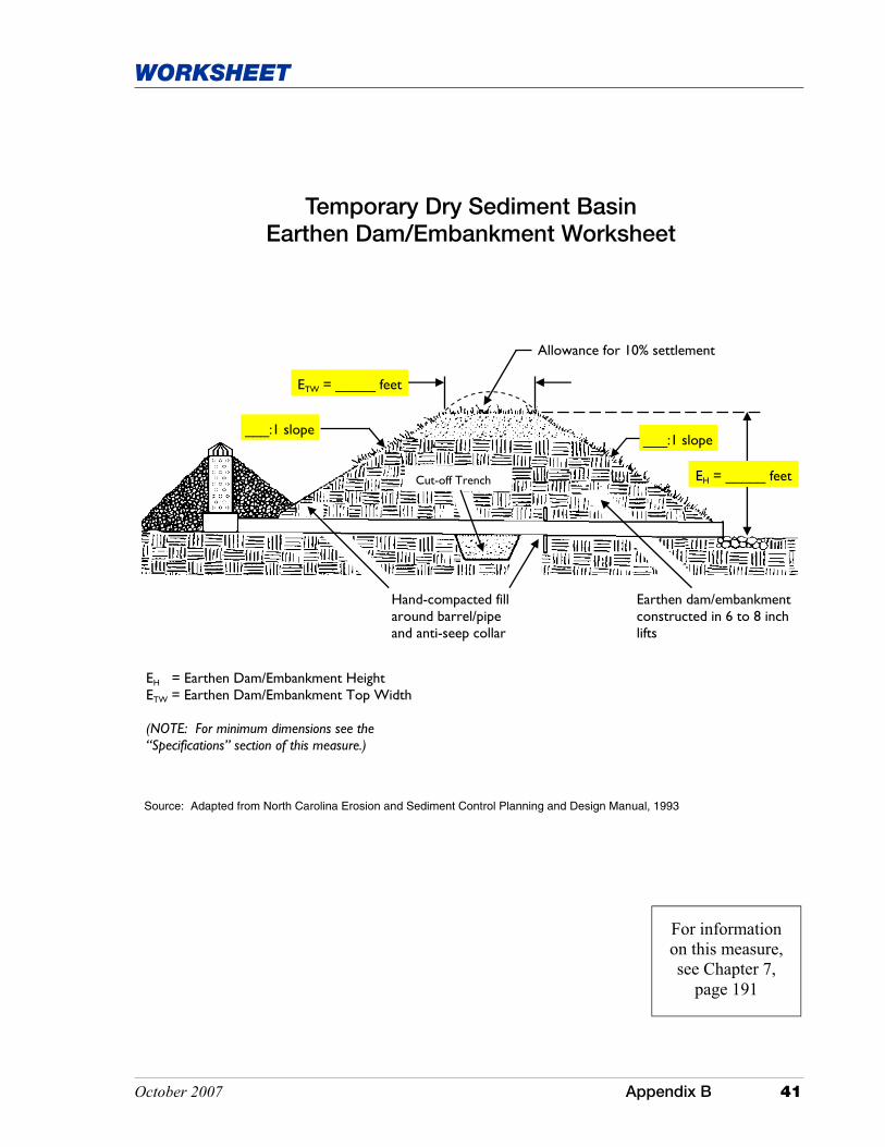
Temporary Dry Sediment Basin Earthen Dam/Embankment Worksheet
Hand-compacted fill around barrel/pipe and anti-seep collar
EH = _____ feet
ETW = _____ feet
___:1 slope ___:1 slope
Allowance for 10% settlement
EH = Earthen Dam/Embankment Height ETW = Earthen Dam/Embankment Top Width (NOTE: For minimum dimensions see the “Specifications” section of this measure.)
Earthen dam/embankment constructed in 6 to 8 inch lifts
Cut-off Trench
Source: Adapted from North Carolina Erosion and Sediment Control Planning and Design Manual, 1993
For information on this measure, see Chapter 7,
page 191

This page was intentionally left blank.
October 2007 Appendix B 43
WORKSHEET
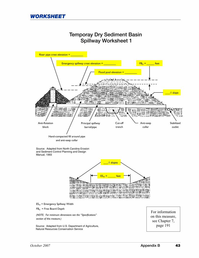
Temporay Dry Sediment Basin Spillway Worksheet 1
Anti-flotation block
Hand-compacted fill around pipe and anti-seep collar
Principal spillway barrel/pipe
Cut-off trench
Anti-seep collar
Stabilized outlet
___:1 slope
Emergency spillway crest elevation = ________ FBD = _____ feet
Flood pool elevation = ________
Riser pipe crest elevation = ________
Source: Adapted from North Carolina Erosion and Sediment Control Planning and Design Manual, 1993
ESW = Emergency Spillway Width
FBD = Free Board Depth
(NOTE: For minimum dimensions see the “Specifications” section of this measure.)
ESW = _____ feet
___:1 slopes
Source: Adapted from U.S. Department of Agriculture, Natural Resources Conservation Service
For information on this measure, see Chapter 7,
page 191

This page was intentionally left blank.

October 2007 Appendix B 45
WORKSHEET
Earthen dam/embankment
Slope
Flow ESW = _____ feet
Slope
Level portion of spillway
Channel approach
1.5 ESW = _____ feet
FBD = _____ feet
LSL = _____ feet
Exit section
Flood pool
Approach channel
___:1 slope
___:1 slope
ESW = Emergency Spillway Width
FBD = Free Board Depth
LSL = Level Section Length
(NOTE: For minimum dimensions see the “Specifications” section of this measure.)
Temporary Dry Sediment Basin Spillway Worksheet 2
Source: Adapted from USDA Natural Resources Conservation Service
For information on this measure, see Chapter 7,
page 191

This page was intentionally left blank.
October 2007 Appendix B 47
WORKSHEET
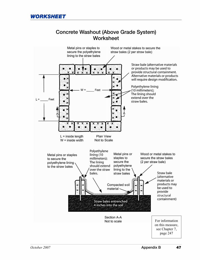
Concrete Washout (Above Grade System) Worksheet
For information on this measure, see Chapter 7,
page 247

This page was intentionally left blank.
October 2007 Appendix B 49
WORKSHEET
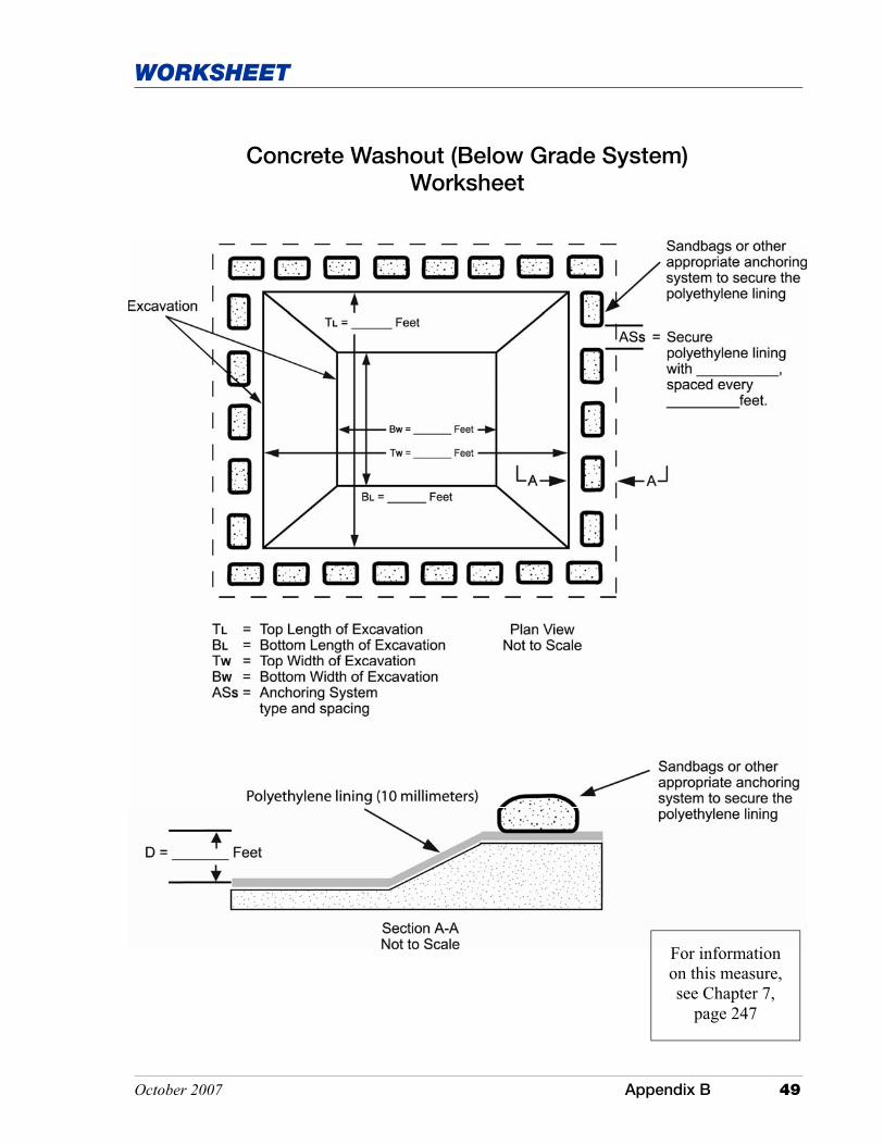
Concrete Washout (Below Grade System) Worksheet
For information on this measure, see Chapter 7,
page 247

This page was intentionally left blank.

October 2007 Appendix B 51
WORKSHEET
H = ____ inches
V = _____ inches Slope
H = Horizontal Cut V = Vertical Cut H > V Note: See “Roughening Slopes (Not to be Mowed)” under the “Specifications” section of this measure.
Surface Roughening – Stair-Step Worksheet
Source: Adapted from North Carolina Erosion and Sediment Control Planning and Design Manual, 1993
For information on this measure, see Chapter 7,
page 297

This page was intentionally left blank.
October 2007 Appendix B 53
WORKSHEET
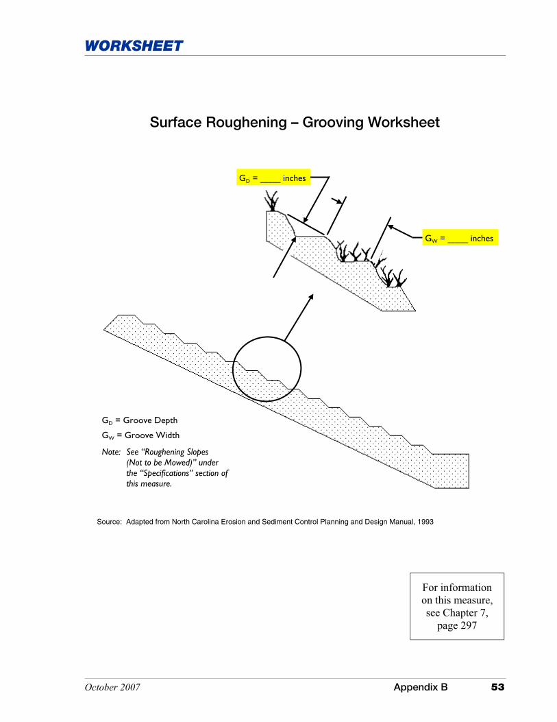
Surface Roughening – Grooving Worksheet
GW = ____ inches
GD = ____ inches
GD = Groove Depth
GW = Groove Width
Note: See “Roughening Slopes (Not to be Mowed)” under the “Specifications” section of this measure.
Source: Adapted from North Carolina Erosion and Sediment Control Planning and Design Manual, 1993
For information on this measure, see Chapter 7,
page 297

This page was intentionally left blank.
October 2007 Appendix B 55
EXHIBIT
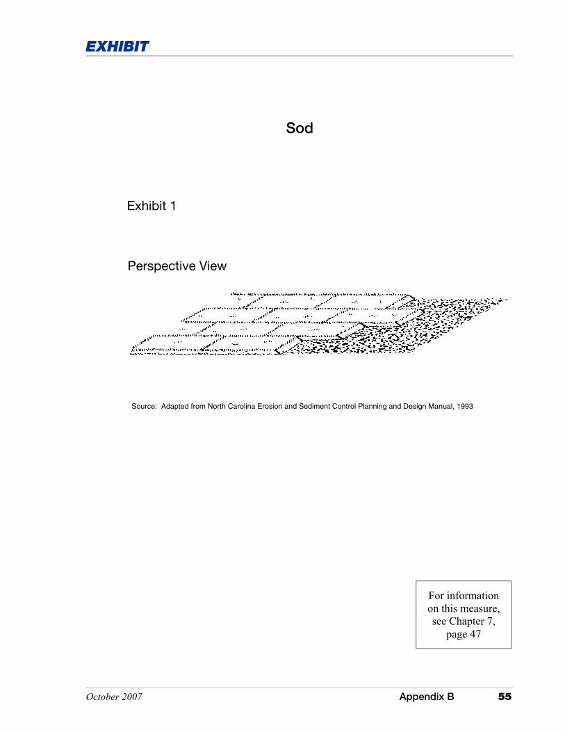
Sod
Exhibit 1
Perspective View
Source: Adapted from North Carolina Erosion and Sediment Control Planning and Design Manual, 1993
For information on this measure, see Chapter 7,
page 47

This page was intentionally left blank.
October 2007 Appendix B 57
EXHIBIT
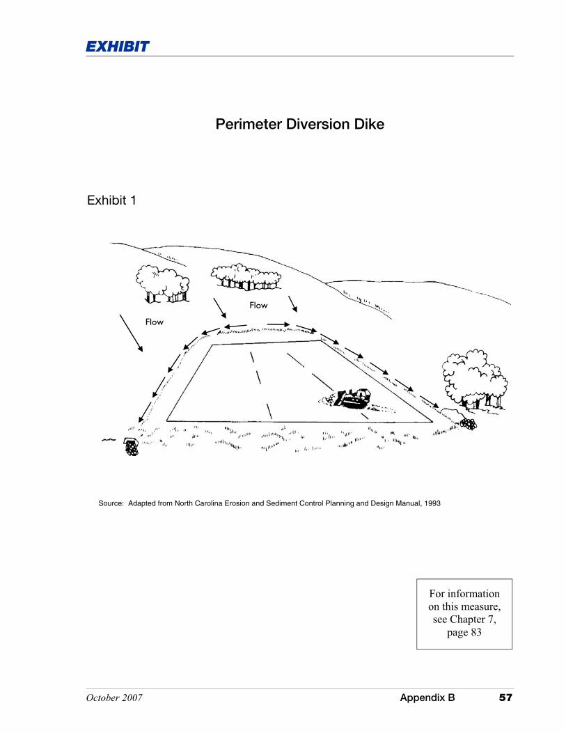
Flow
Flow
Perimeter Diversion Dike
Exhibit 1
Source: Adapted from North Carolina Erosion and Sediment Control Planning and Design Manual, 1993
For information on this measure, see Chapter 7,
page 83

This page was intentionally left blank.
October 2007 Appendix B 59
EXHIBIT
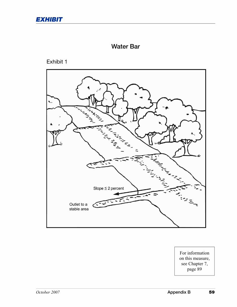
Water Bar
Exhibit 1
For information on this measure, see Chapter 7,
page 89

This page was intentionally left blank.
October 2007 Appendix B 61
EXHIBIT
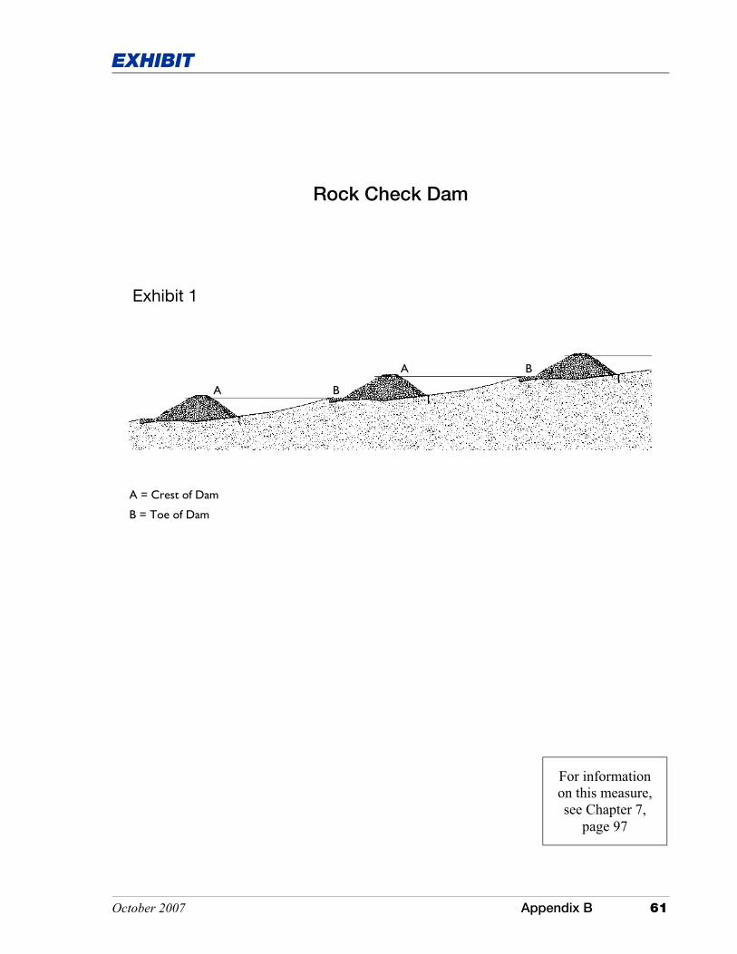
Rock Check Dam
Exhibit 1
A B
A B
A = Crest of Dam
B = Toe of Dam
For information on this measure, see Chapter 7,
page 97

This page was intentionally left blank.

October 2007 Appendix B 63
EXHIBIT
Channel bottom width
Channel top width
Flow
Revetment riprap
Filter medium
Exhibit 2
Rock Check Dam
For information on this measure, see Chapter 7,
page 97

This page was intentionally left blank.

October 2007 Appendix B 65
EXHIBIT
Temporary Slope Drain
Exhibit 1
Flow
Earthen island over inlet section of drain
Anchor stake spacing (maximum of 10 feet)
Stablized outlet
Level section (4 foot min.)
Diversion berm Diversion channel
Anchor stakes
Corrugated, non-perforated, plastic drain pipe
For information on this measure, see Chapter 7,
page 103

This page was intentionally left blank.
October 2007 Appendix B 67
EXHIBIT
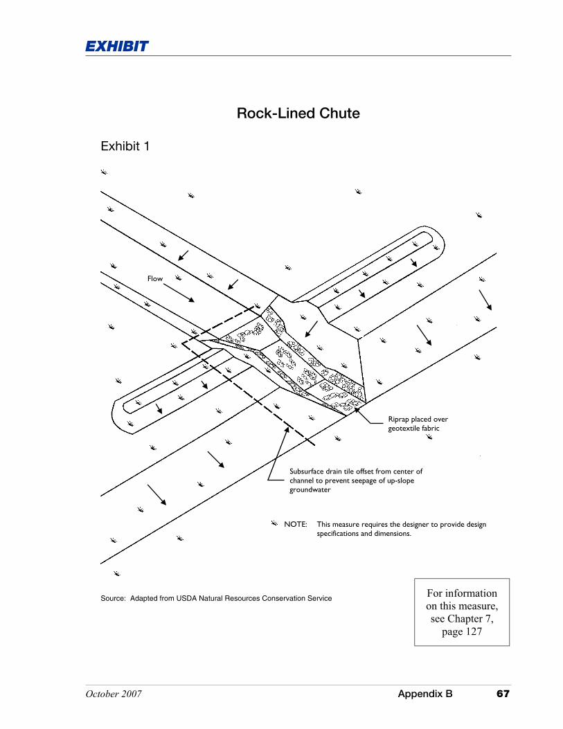
Flow
Riprap placed over geotextile fabric
Subsurface drain tile offset from center of channel to prevent seepage of up-slope groundwater
Rock-Lined Chute
Exhibit 1
Source: Adapted from USDA Natural Resources Conservation Service
NOTE: This measure requires the designer to provide design specifications and dimensions.
For information on this measure, see Chapter 7,
page 127

This page was intentionally left blank.
October 2007 Appendix B 69
EXHIBIT
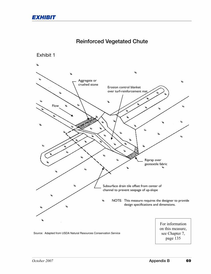
Source: Adapted from USDA Natural Resources Conservation Service
Reinforced Vegetated Chute
Flow
Subsurface drain tile offset from center of channel to prevent seepage of up-slope
Riprap over geotextile fabric
Erosion control blanket over turf-reinforcement mat
Aggregate or crushed stone
Exhibit 1
NOTE: This measure requires the designer to provide design specifications and dimensions.
For information on this measure, see Chapter 7,
page 135

This page was intentionally left blank.

October 2007 Appendix B 71
EXHIBIT
Excavated Drop Inlet Protection
Flow Flow
Flow
Main Flow
Exhibit 1
Source: Adapted from North Carolina Erosion and Sediment Control Planning and Design Manual, 1993
For information on this measure, see Chapter 7,
page 145

This page was intentionally left blank.
October 2007 Appendix B 73
EXHIBIT
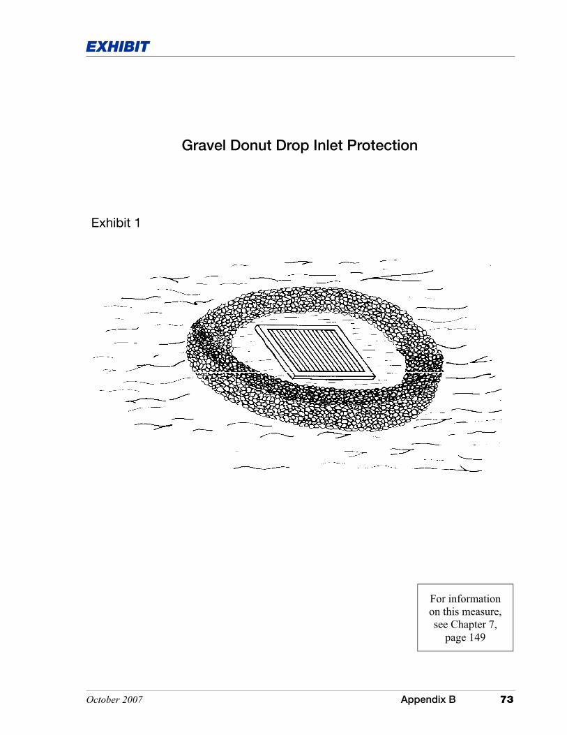
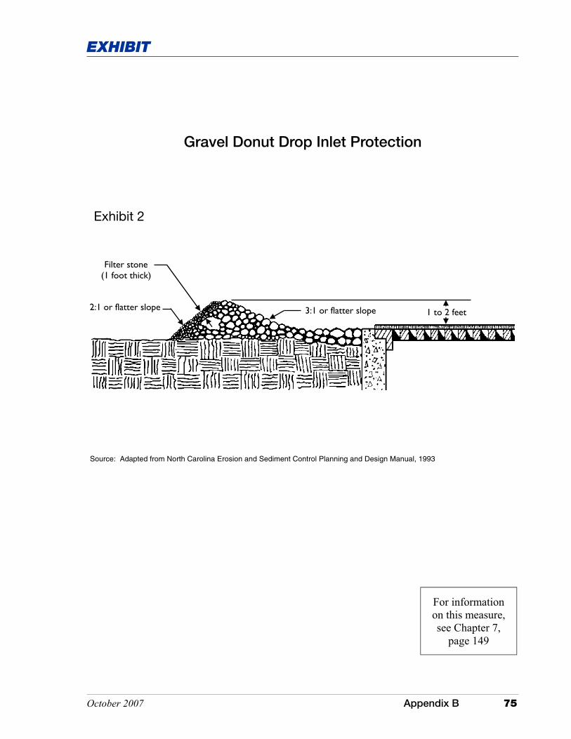
Gravel Donut Drop Inlet Protection
Exhibit 1
For information on this measure, see Chapter 7,
page 149

This page was intentionally left blank.
October 2007 Appendix B 75
EXHIBIT
3:1 or flatter slope 1 to 2 feet 2:1 or flatter slope
Filter stone (1 foot thick)
Exhibit 2
Gravel Donut Drop Inlet Protection
Source: Adapted from North Carolina Erosion and Sediment Control Planning and Design Manual, 1993
For information on this measure, see Chapter 7,
page 149

This page was intentionally left blank.

October 2007 Appendix B 77
EXHIBIT
36 inches (maximum)
12 to 18 inches
18 inches (minimum)
Cross bracing
Exhibit 1
Geotextile Fabric Drop Inlet Protection
Source: Adapted from North Carolina Erosion and Sediment Control Planning and Design Manual, 1993
For information on this measure, see Chapter 7,
page 153

This page was intentionally left blank.
October 2007 Appendix B 79
EXHIBIT
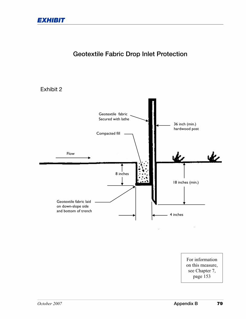
Geotextile Fabric Drop Inlet Protection
Exhibit 2
Flow
Compacted fill
Geotextile fabric
8 inches
18 inches (min.)
36 inch (min.) hardwood post
Geotextile fabric laid on down-slope side and bottom of trench
4 inches
Secured with lathe
For information on this measure, see Chapter 7,
page 153

This page was intentionally left blank.

October 2007 Appendix B 81
EXHIBIT
Two stakes per straw bale
Exhibit 1
Straw Bale Drop Inlet Protection
Source: Adapted from Michigan Soil Erosion and Sedimentation Control Guidebook, 1975
For information on this measure, see Chapter 7,
page 159

This page was intentionally left blank.

October 2007 Appendix B 83
EXHIBIT
Straw Bale Drop Inlet Protection
Exhibit 2
Bales entrenched four (4) inches into the soil
Compacted fill to prevent piping
Flow
Bale turned on its side to prevent deterioration of bindings
Source: Adapted from Michigan Soil Erosion and Sedimentation Control Guidebook, 1975
For information on this measure, see Chapter 7,
page 159

This page was intentionally left blank.

October 2007 Appendix B 85
EXHIBIT
Block & Gravel Drop Inlet Protection
One concrete block, in bottom row of blocks on each side of structure, laid horizontally to allow for dewatering
Aggregate blanket with 2:1 slope or flatter
Exhibit 1
Source: Adapted from North Carolina Erosion and Sediment Control Planning and Design Manual, 1993
For information on this measure, see Chapter 7,
page 163

This page was intentionally left blank.

October 2007 Appendix B 87
EXHIBIT
Block & Gravel Drop Inlet Protection
2:1 or flatter slope
Concrete block laid horizontally for dewatering
Hardware cloth
Exhibit 2
Source: Adapted from North Carolina Erosion and Sediment Control Planning and Design Manual, 1993
For information on this measure, see Chapter 7,
page 163

This page was intentionally left blank.
October 2007 Appendix B 89
EXHIBIT
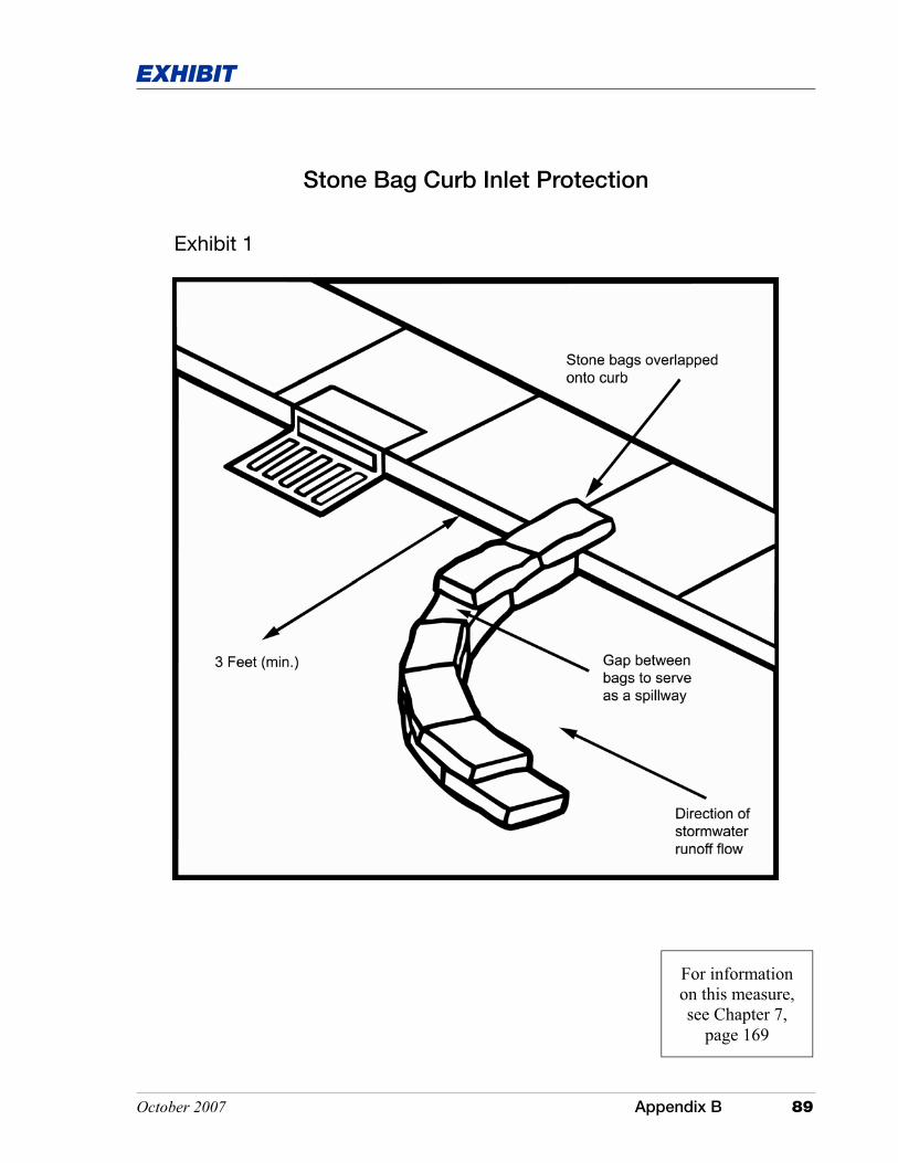
Stone Bag Curb Inlet Protection
Exhibit 1
For information on this measure, see Chapter 7,
page 169

This page was intentionally left blank.

October 2007 Appendix B 91
EXHIBIT
Stone Bag Curb Inlet Protection
Flow
Flow
Spillway at or below curb height
Stone bags tightly stacked and abutted together
Upper layer(s) of stone bags overlapped onto back of curb
Exhibit 2
For information on this measure, see Chapter 7,
page 169

This page was intentionally left blank.

October 2007 Appendix B 93
EXHIBIT
Block & Gravel Curb Inlet Protection
Exhibit 1
Source: Adapted from Virginia Department of Conservation and Recreation, Division of Soil and Water Conservation
For information on this measure, see Chapter 7,
page 173

This page was intentionally left blank.

October 2007 Appendix B 95
EXHIBIT
2” x 4” wooden stud
Filter aggregate
Blocks laid with openings horizontal to the pavement to allow for drainage
Hardware cloth
Exhibit 2
Block & Gravel Curb Inlet Protection
For information on this measure, see Chapter 7,
page 173

This page was intentionally left blank.
October 2007 Appendix B 97
EXHIBIT
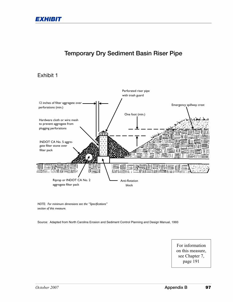
Temporary Dry Sediment Basin Riser Pipe
Hardware cloth or wire mesh to prevent aggregate from plugging perforations
Riprap or INDOT CA No. 2 aggregate filter pack
INDOT CA No. 5 aggre-gate filter stone over filter pack
12 inches of filter aggregate over perforations (min.)
Perforated riser pipe with trash guard
One foot (min.)
Emergency spillway crest
Anti-flotation block
NOTE: For minimum dimensions see the “Specifications” section of this measure.
Exhibit 1
Source: Adapted from North Carolina Erosion and Sediment Control Planning and Design Manual, 1993
For information on this measure, see Chapter 7,
page 191

This page was intentionally left blank.

October 2007 Appendix B 99
EXHIBIT
Silt Fence
End of silt fence turned up-slope to prevent bypass flow and allow for ponding of stormwater runoff
95
100
105
Exhibit 1
Source: Adapted from Commonwealth of Pennsylvania Erosion and Sediment Pollution Control Program Manual, 1990
Silt Fence
For information on this measure, see Chapter 7,
page 215

This page was intentionally left blank.

October 2007 Appendix B 101
EXHIBIT
Silt Fence
Flow
Compacted fill
8 inches
18 inches (min.)
Geotextile fabric
36 inch (min.) hardwood post
Geotextile fabric laid on down-slope side and bottom of trench
4 inches
Exhibit 2
secured with lathe
For information on this measure, see Chapter 7,
page 215

This page was intentionally left blank.

October 2007 Appendix B 103
EXHIBIT
Silt Fence
Silt Fence Post
Exhibit 3
For information on this measure, see Chapter 7,
page 215

This page was intentionally left blank.
October 2007 Appendix B 105
EXHIBIT
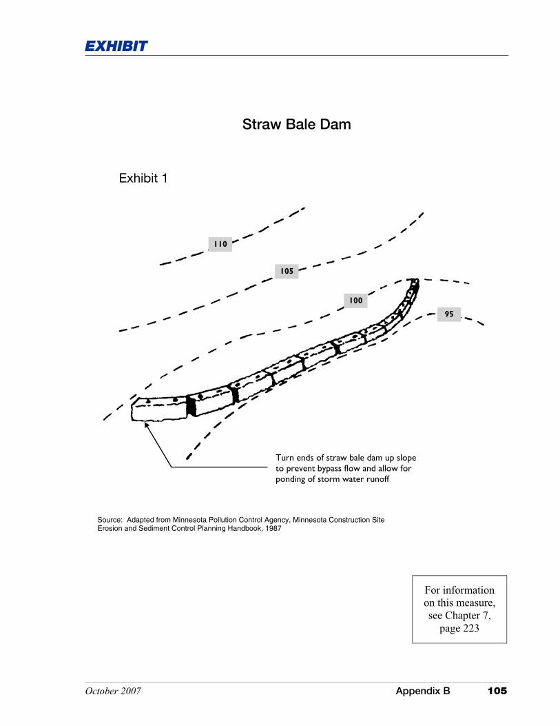
Straw Bale Dam
110
105
100
95
Turn ends of straw bale dam up slope to prevent bypass flow and allow for ponding of storm water runoff
Exhibit 1
Source: Adapted from Minnesota Pollution Control Agency, Minnesota Construction Site Erosion and Sediment Control Planning Handbook, 1987
For information on this measure, see Chapter 7,
page 223

This page was intentionally left blank.
October 2007 Appendix B 107
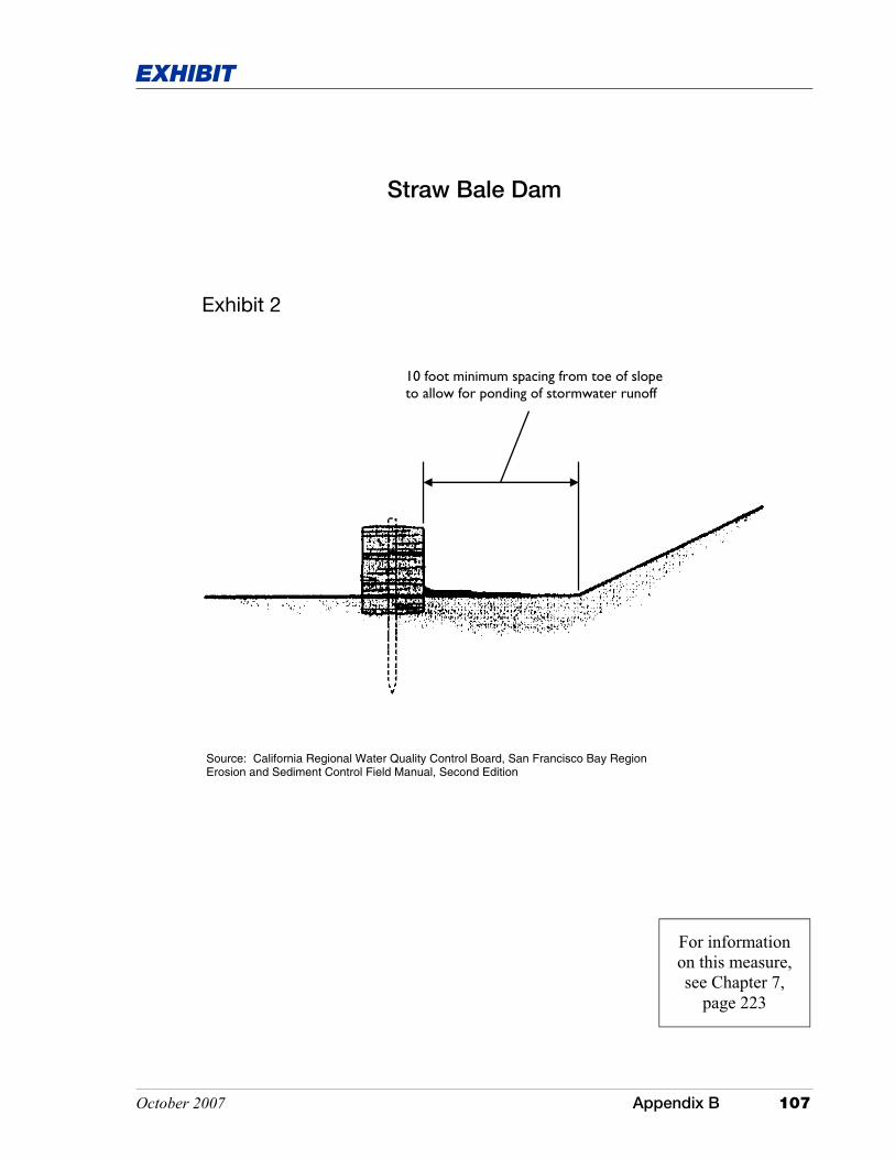
EXHIBIT
10 foot minimum spacing from toe of slope to allow for ponding of stormwater runoff
Straw Bale Dam
Exhibit 2
Source: California Regional Water Quality Control Board, San Francisco Bay Region Erosion and Sediment Control Field Manual, Second Edition
For information on this measure, see Chapter 7,
page 223

This page was intentionally left blank.

October 2007 Appendix B 109
EXHIBIT
Straw Bale Dam
Exhibit 3
For information on this measure, see Chapter 7,
page 223

This page was intentionally left blank.

October 2007 Appendix B 111
EXHIBIT
Straw Bale Dam
Exhibit 4
For information on this measure, see Chapter 7,
page 223

This page was intentionally left blank.

October 2007 Appendix B 113
EXHIBIT
Temporary Stream Crossing - Bridges
Exhibit 1
NOTE: This measure requires the designer to provide design specifications and dimensions.
For information on this measure, see
Chapter 7, page 267

This page was intentionally left blank.
October 2007 Appendix B 115
EXHIBIT
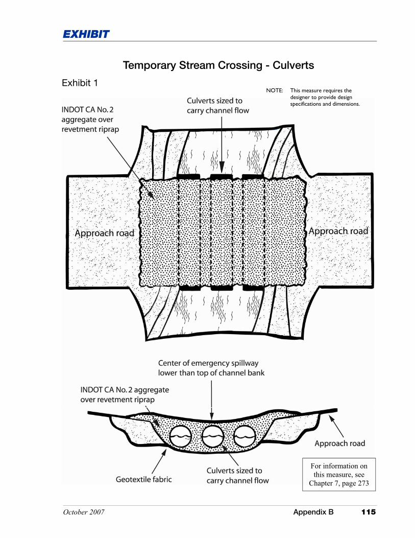
Temporary Stream Crossing - Culverts
Exhibit 1 NOTE: This measure requires the
designer to provide design specifications and dimensions.
For information on this measure, see
Chapter 7, page 273

This page was intentionally left blank.
October 2007 Appendix B 117
EXHIBIT
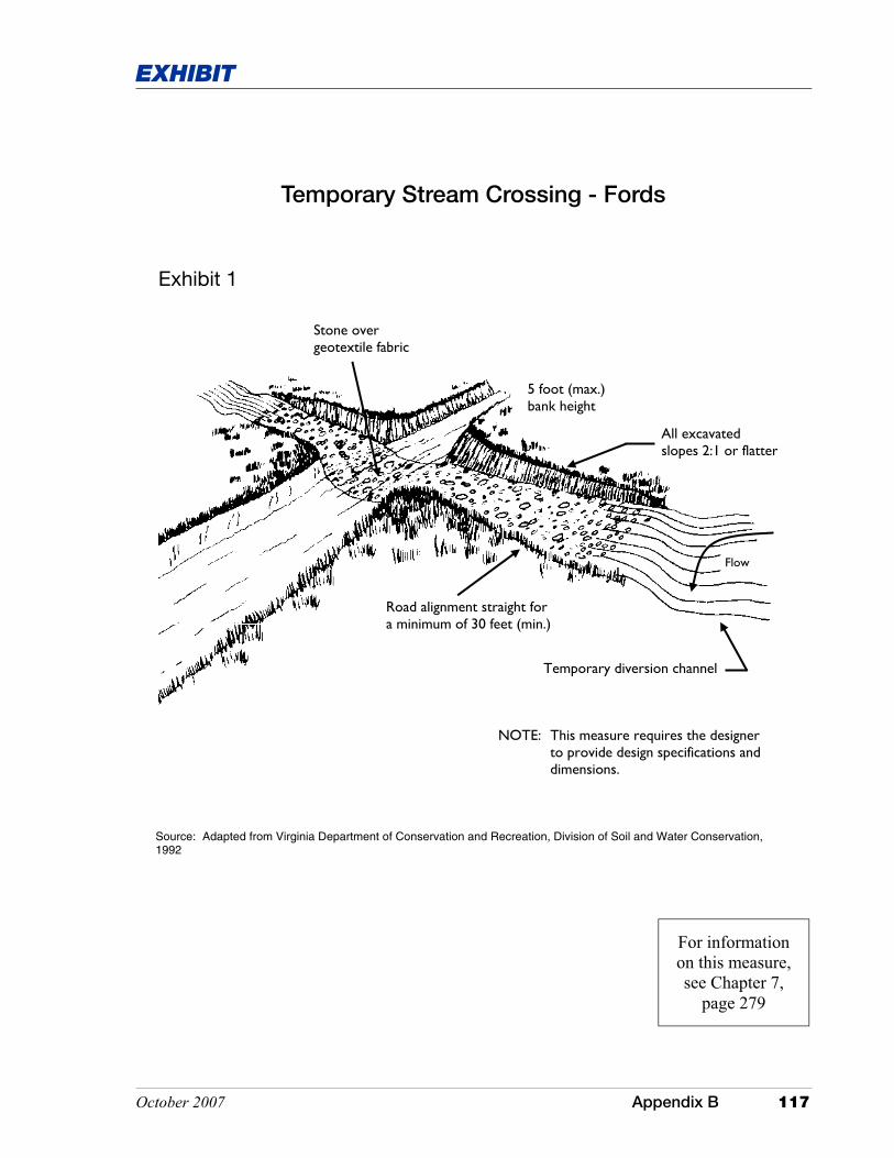
Temporary Stream Crossing - Fords
5 foot (max.) bank height
Stone over geotextile fabric
Road alignment straight for a minimum of 30 feet (min.)
All excavated slopes 2:1 or flatter
Flow
Temporary diversion channel
Exhibit 1
Source: Adapted from Virginia Department of Conservation and Recreation, Division of Soil and Water Conservation, 1992
NOTE: This measure requires the designer to provide design specifications and dimensions.
For information on this measure, see Chapter 7,
page 279

This page was intentionally left blank.
October 2007 Appendix B 119
EXHIBIT
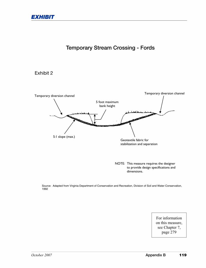
Temporary Stream Crossing - Fords
Temporary diversion channel
5:1 slope (max.) Geotextile fabric for stabilization and separation
Temporary diversion channel
5 foot maximum bank height
Exhibit 2
Source: Adapted from Virginia Department of Conservation and Recreation, Division of Soil and Water Conservation, 1992
NOTE: This measure requires the designer to provide design specifications and dimensions.
For information on this measure, see Chapter 7,
page 279

This page was intentionally left blank.