Embed Size (px)
Citation preview
ALA WAI CANAL FLOOD RISK MANAGEMENT STUDY O’AHU, HAWAI’I
FINAL FEASIBILITY STUDY REPORT WITH INTEGRATED
ENVIRONMENTAL IMPACT STATEMENT
APPENDIX H VALUE ENGINEERING STUDY

This page is intentionally left blank.
0
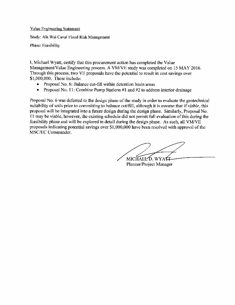
VALUE ENGINEERING STUDY SUMMARY REPORT
Prepared for US Army Corps of Engineers
Ala Wai Canal
Honolulu, Hawaii
Value Engineering Report
May 15, 2016
1
VALUE ENGINEERING TEAM STUDY
DOD SERVICE: USACE VE OFFICER: Elton Choy
Value Engineering Study Report on
Ala Wai Canal
Honolulu, Hawaii
STUDY SPONSOR: U.S. Army Engineering District, Honolulu (POH)
VALUE ENGINEERING FIRM NAME: U.S. Army Corps of Engineers, Honolulu District
VALUE ENGINEERING STUDY TEAM FACILITATOR: Charles W. Fore, Jr., PE, CVS
VALUE ENGINEERING STUDY TEAM MEMBERS:
Cost Engineer: Tracy Kazunaga, USACE, POH
Civil Engineer: Michael Wong, USACE, POH
Cost Engineer & VEO: Elton Choy, USACE, POH
Cost Engineer: Patrick Miramontez, USACE, NWK
Civil Engineer & PM: Michael Wyatt, USACE, POH
2
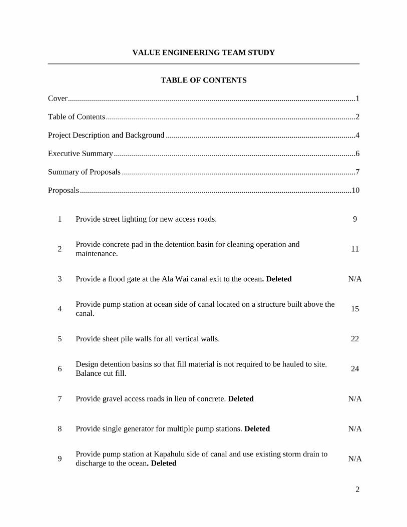
VALUE ENGINEERING TEAM STUDY
TABLE OF CONTENTS
Cover ................................................................................................................................................1
Table of Contents .............................................................................................................................2
Project Description and Background ...............................................................................................4
Executive Summary .........................................................................................................................6
Summary of Proposals .....................................................................................................................7
Proposals ........................................................................................................................................10
1 Provide street lighting for new access roads. 9
2 Provide concrete pad in the detention basin for cleaning operation and
maintenance. 11
3 Provide a flood gate at the Ala Wai canal exit to the ocean. Deleted N/A
4 Provide pump station at ocean side of canal located on a structure built above the
canal. 15
5 Provide sheet pile walls for all vertical walls. 22
6 Design detention basins so that fill material is not required to be hauled to site.
Balance cut fill. 24
7 Provide gravel access roads in lieu of concrete. Deleted N/A
8 Provide single generator for multiple pump stations. Deleted N/A
9 Provide pump station at Kapahulu side of canal and use existing storm drain to
discharge to the ocean. Deleted N/A
3
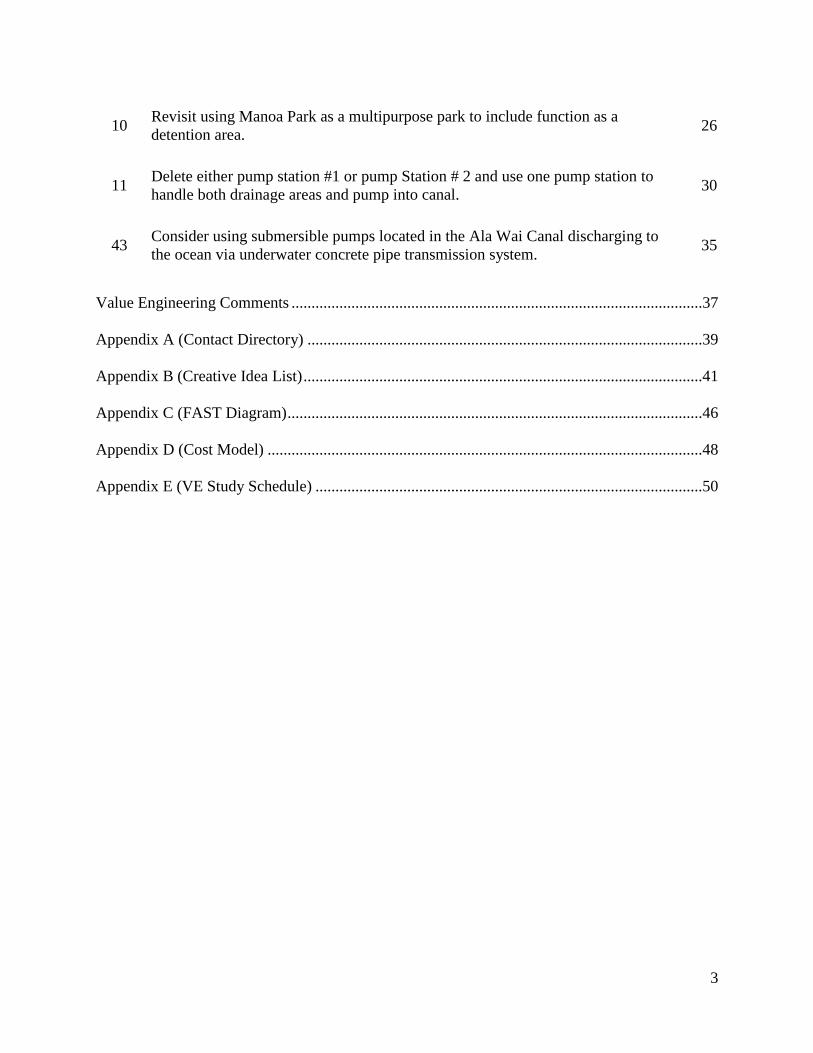
10 Revisit using Manoa Park as a multipurpose park to include function as a
detention area. 26
11 Delete either pump station #1 or pump Station # 2 and use one pump station to
handle both drainage areas and pump into canal. 30
43 Consider using submersible pumps located in the Ala Wai Canal discharging to
the ocean via underwater concrete pipe transmission system. 35
Value Engineering Comments .......................................................................................................37
Appendix A (Contact Directory) ...................................................................................................39
Appendix B (Creative Idea List) ....................................................................................................41
Appendix C (FAST Diagram) ........................................................................................................46
Appendix D (Cost Model) .............................................................................................................48
Appendix E (VE Study Schedule) .................................................................................................50
4
VALUE ENGINEERING TEAM STUDY
PROJECT DESCRIPTION AND BACKGROUND:
PROJECT TITLE: Ala Wai Canal
PROJECT LOCATION: Honolulu, Hawaii
Project Description:
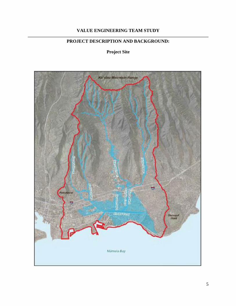
The Ala Wai watershed is located on the southeastern side of the island of Oahu, Hawaii. The
watershed encompasses 19 square miles (12,064 acres) and extends from the ridge of the
Ko’olau Mountains to the nearshore of Mamala Bay. It includes Makiki, Manoa and Palolo
streams, which flow to the Ala Wai Canal. The Ala Wai Canal is a 2-mile long, man-made
waterway constructed during the 1920’s to drain extensive coastal wetlands. This construction
and subsequent draining allowed development of the Waikiki District.
The Ala Wai Watershed contains approximately 200,000 residents and is the most densely
watershed in Hawaii. This watershed contains residential, commercial, educational and
recreational facilities. The Waikiki District is a prime tourist destination that attacks more than
79,000 visitors per day. Because of the tourism industry, Waikiki is the primary economic engine
for the state, providing 7 percent of the gross state product, 7 percent of the civilian jobs in the
state and 9 percent of the State and County tax revenue.
The recommended plan of action by the Feasibility Study is to created debris/retention basins,
add three pump stations, and add flood walls to the Ala Wai Canal.
The Total Investment Cost for this project is $176,427,000 (Based on the Feasibility Study dated
August 2015). Based on a 3.375% discount rate, this investment results in a 2.38 benefit/cost
(B/C) ratio.
5
VALUE ENGINEERING TEAM STUDY
PROJECT DESCRIPTION AND BACKGROUND:
Project Site
6
VALUE ENGINEERING TEAM STUDY
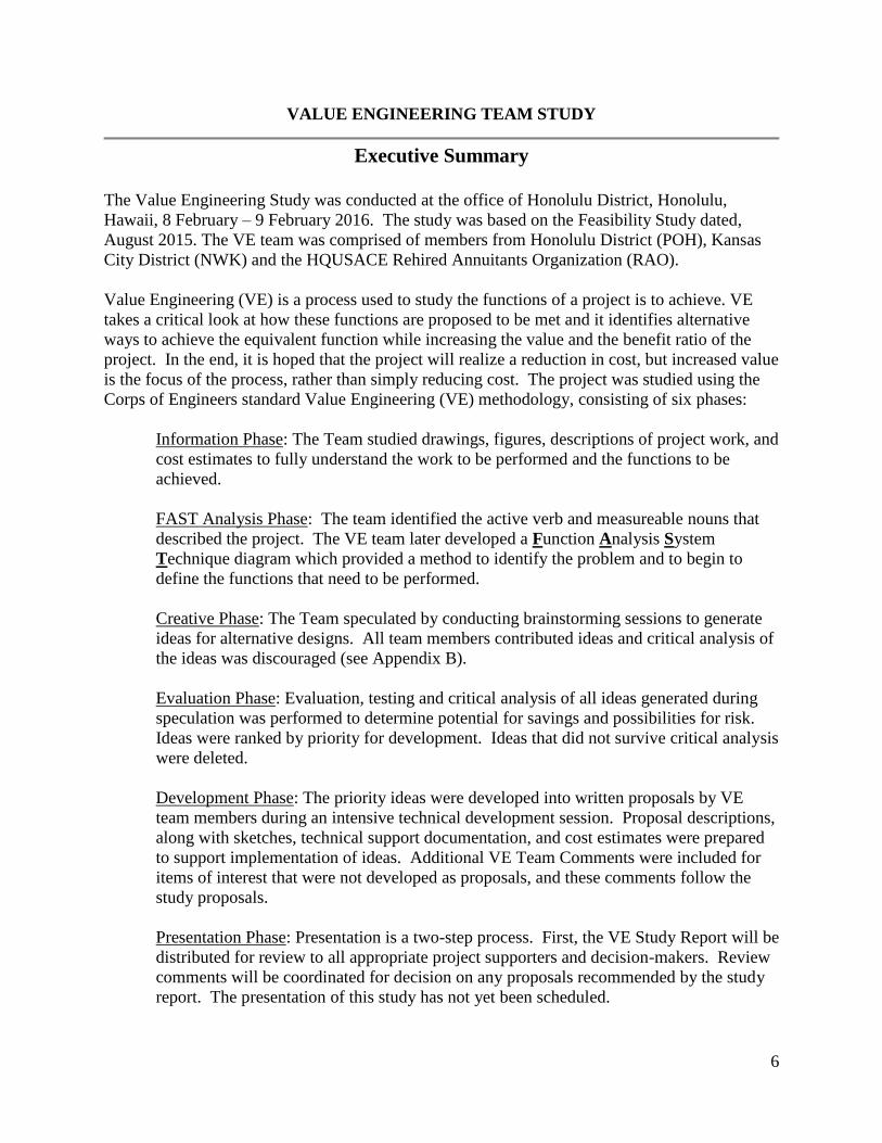
Executive Summary
The Value Engineering Study was conducted at the office of Honolulu District, Honolulu,
Hawaii, 8 February – 9 February 2016. The study was based on the Feasibility Study dated,
August 2015. The VE team was comprised of members from Honolulu District (POH), Kansas
City District (NWK) and the HQUSACE Rehired Annuitants Organization (RAO).
Value Engineering (VE) is a process used to study the functions of a project is to achieve. VE
takes a critical look at how these functions are proposed to be met and it identifies alternative
ways to achieve the equivalent function while increasing the value and the benefit ratio of the
project. In the end, it is hoped that the project will realize a reduction in cost, but increased value
is the focus of the process, rather than simply reducing cost. The project was studied using the
Corps of Engineers standard Value Engineering (VE) methodology, consisting of six phases:
Information Phase: The Team studied drawings, figures, descriptions of project work, and
cost estimates to fully understand the work to be performed and the functions to be
achieved.
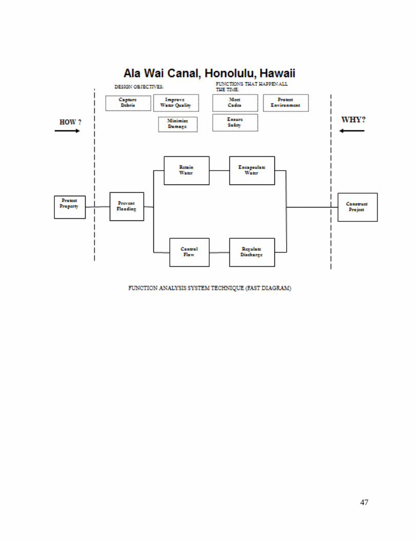
FAST Analysis Phase: The team identified the active verb and measureable nouns that
described the project. The VE team later developed a Function Analysis System
Technique diagram which provided a method to identify the problem and to begin to
define the functions that need to be performed.
Creative Phase: The Team speculated by conducting brainstorming sessions to generate
ideas for alternative designs. All team members contributed ideas and critical analysis of
the ideas was discouraged (see Appendix B).
Evaluation Phase: Evaluation, testing and critical analysis of all ideas generated during
speculation was performed to determine potential for savings and possibilities for risk.
Ideas were ranked by priority for development. Ideas that did not survive critical analysis
were deleted.
Development Phase: The priority ideas were developed into written proposals by VE
team members during an intensive technical development session. Proposal descriptions,
along with sketches, technical support documentation, and cost estimates were prepared
to support implementation of ideas. Additional VE Team Comments were included for
items of interest that were not developed as proposals, and these comments follow the
study proposals.
Presentation Phase: Presentation is a two-step process. First, the VE Study Report will be
distributed for review to all appropriate project supporters and decision-makers. Review
comments will be coordinated for decision on any proposals recommended by the study
report. The presentation of this study has not yet been scheduled.
7
VALUE ENGINEERING TEAM STUDY
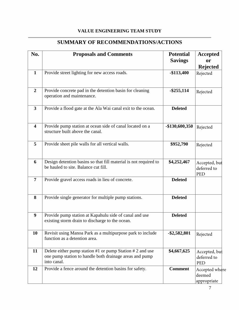
SUMMARY OF RECOMMENDATIONS/ACTIONS
No. Proposals and Comments Potential
Savings
Accepted
or
Rejected 1 Provide street lighting for new access roads. -$113,400
2 Provide concrete pad in the detention basin for cleaning
operation and maintenance. -$255,114
3 Provide a flood gate at the Ala Wai canal exit to the ocean. Deleted
4 Provide pump station at ocean side of canal located on a
structure built above the canal. -$130,600,350
5 Provide sheet pile walls for all vertical walls. $952,790
6 Design detention basins so that fill material is not required to
be hauled to site. Balance cut fill. $4,252,467
7 Provide gravel access roads in lieu of concrete. Deleted
8 Provide single generator for multiple pump stations. Deleted
9 Provide pump station at Kapahulu side of canal and use
existing storm drain to discharge to the ocean. Deleted
10 Revisit using Manoa Park as a multipurpose park to include
function as a detention area. -$2,582,801
11 Delete either pump station #1 or pump Station # 2 and use
one pump station to handle both drainage areas and pump
into canal.
$4,667,625
12 Provide a fence around the detention basins for safety. Comment
Rejected
Rejected
Rejected
Rejected
Accepted, but deferred to PED
Rejected
Accepted, but deferred to PEDAccepted where deemed appropriate
8
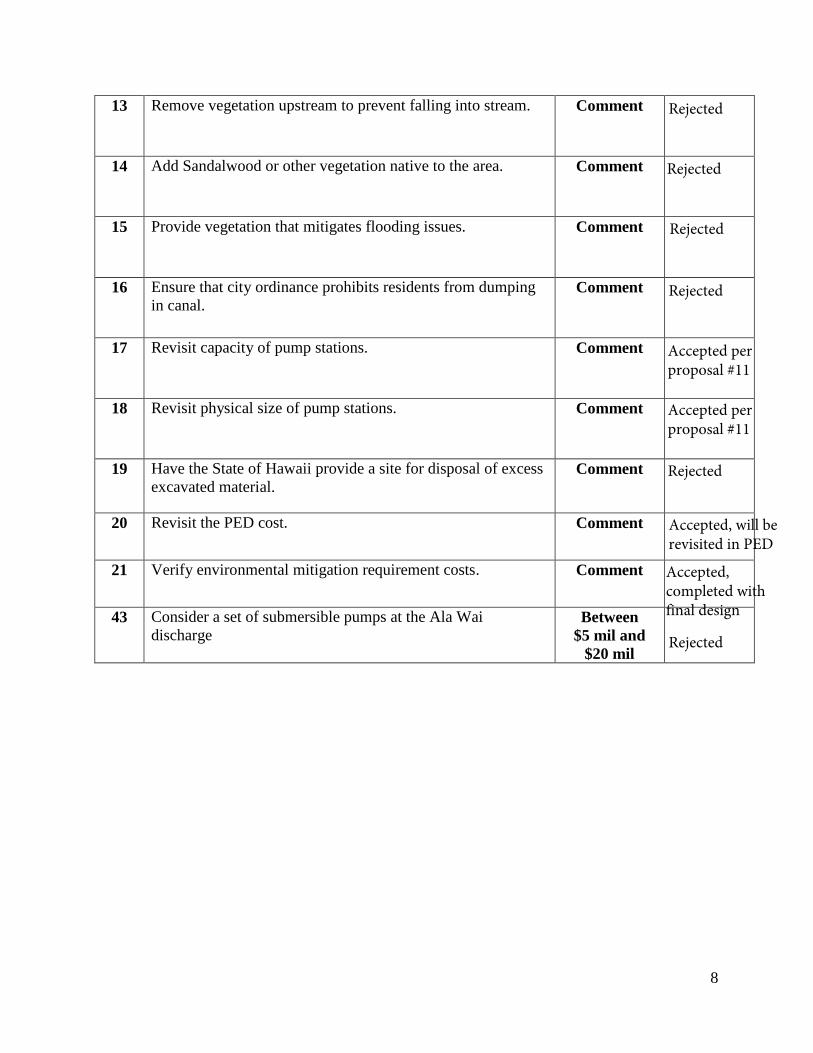
13 Remove vegetation upstream to prevent falling into stream. Comment
14 Add Sandalwood or other vegetation native to the area. Comment
15 Provide vegetation that mitigates flooding issues. Comment
16 Ensure that city ordinance prohibits residents from dumping
in canal. Comment
17 Revisit capacity of pump stations. Comment
18 Revisit physical size of pump stations. Comment
19 Have the State of Hawaii provide a site for disposal of excess
excavated material. Comment
20 Revisit the PED cost. Comment
21 Verify environmental mitigation requirement costs. Comment
43 Consider a set of submersible pumps at the Ala Wai
discharge Between
$5 mil and
$20 mil
Rejected
Rejected
Rejected
Rejected
Accepted per proposal #11
Accepted per proposal #11
Rejected
Accepted, will be revisited in PED
Accepted, completed with final design
Rejected
9
VALUE ENGINEERING PROPOSAL
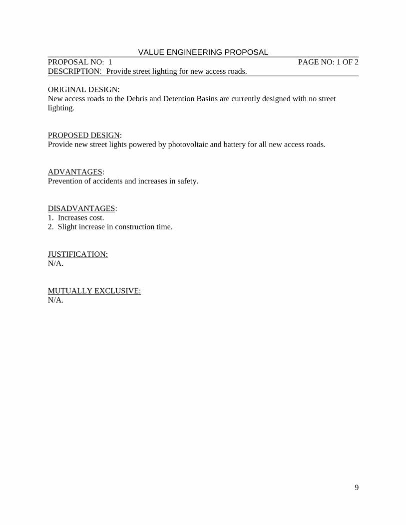
PROPOSAL NO: 1 PAGE NO: 1 OF 2
DESCRIPTION: Provide street lighting for new access roads.
ORIGINAL DESIGN:
New access roads to the Debris and Detention Basins are currently designed with no street
lighting.
PROPOSED DESIGN:
Provide new street lights powered by photovoltaic and battery for all new access roads.
ADVANTAGES:
Prevention of accidents and increases in safety.
DISADVANTAGES:
1. Increases cost.
2. Slight increase in construction time.
JUSTIFICATION:
N/A.
MUTUALLY EXCLUSIVE:
N/A.
10
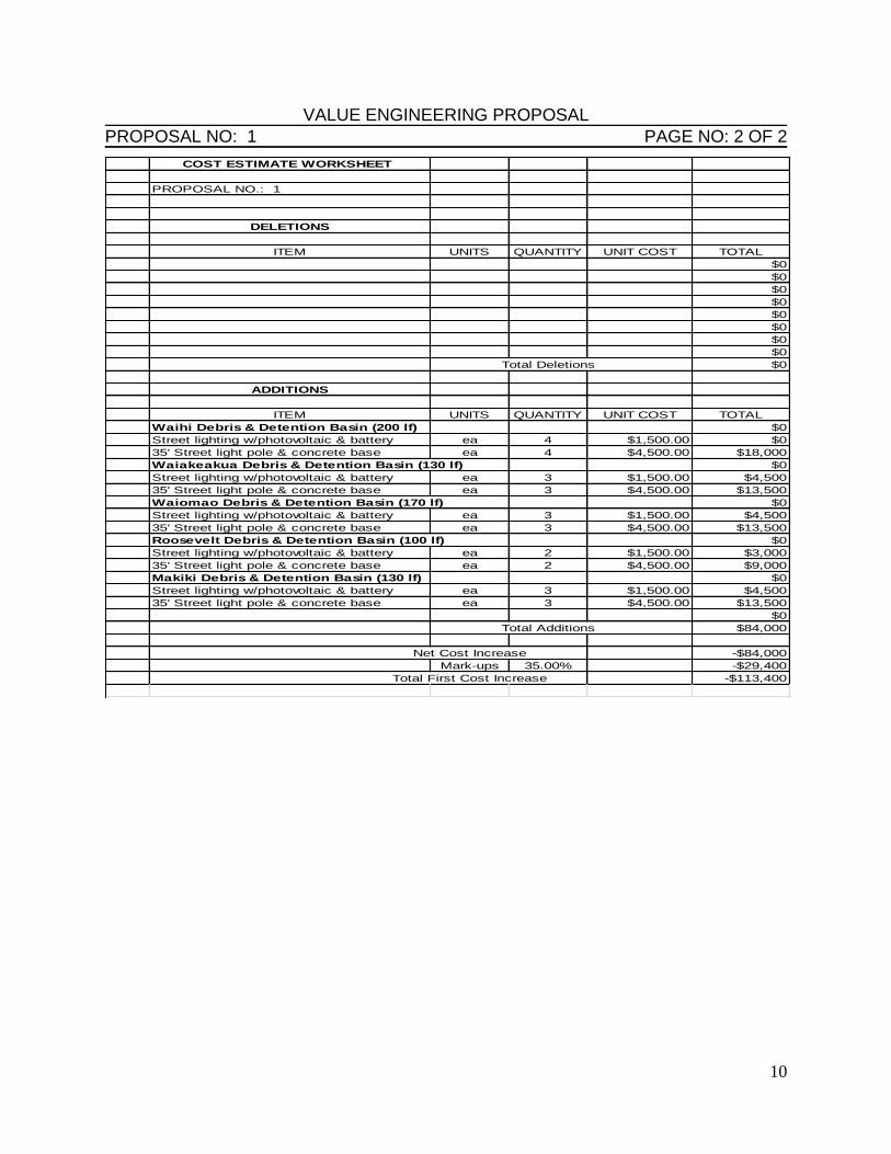
VALUE ENGINEERING PROPOSAL PROPOSAL NO: 1 PAGE NO: 2 OF 2
COST ESTIMATE WORKSHEET
PROPOSAL NO.: 1
DELETIONS
ITEM UNITS QUANTITY UNIT COST TOTAL
$0
$0
$0
$0
$0
$0
$0
$0
Total Deletions $0
ADDITIONS
ITEM UNITS QUANTITY UNIT COST TOTAL
Waihi Debris & Detention Basin (200 lf) $0
Street lighting w/photovoltaic & battery ea 4 $1,500.00 $0
35' Street light pole & concrete base ea 4 $4,500.00 $18,000
Waiakeakua Debris & Detention Basin (130 lf) $0
Street lighting w/photovoltaic & battery ea 3 $1,500.00 $4,500
35' Street light pole & concrete base ea 3 $4,500.00 $13,500
Waiomao Debris & Detention Basin (170 lf) $0
Street lighting w/photovoltaic & battery ea 3 $1,500.00 $4,500
35' Street light pole & concrete base ea 3 $4,500.00 $13,500
Roosevelt Debris & Detention Basin (100 lf) $0
Street lighting w/photovoltaic & battery ea 2 $1,500.00 $3,000
35' Street light pole & concrete base ea 2 $4,500.00 $9,000
Makiki Debris & Detention Basin (130 lf) $0
Street lighting w/photovoltaic & battery ea 3 $1,500.00 $4,500
35' Street light pole & concrete base ea 3 $4,500.00 $13,500
$0
Total Additions $84,000
Net Cost Increase -$84,000
Mark-ups 35.00% -$29,400
Total First Cost Increase -$113,400
11
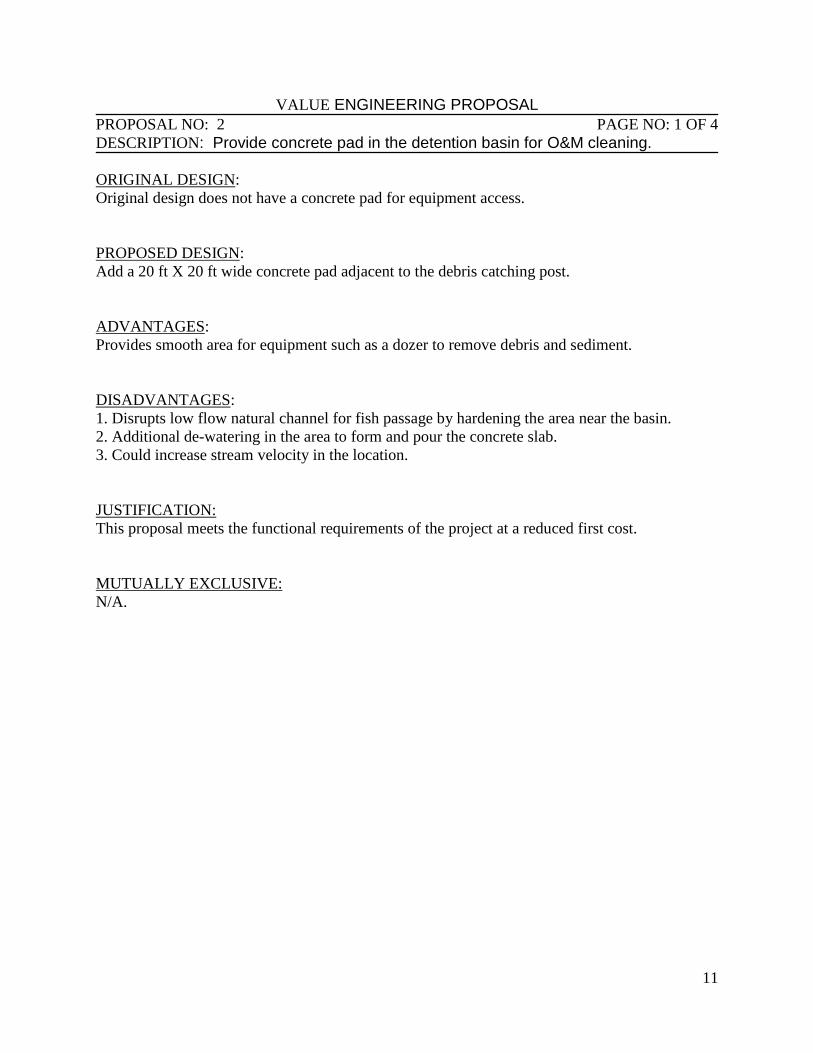
VALUE ENGINEERING PROPOSAL PROPOSAL NO: 2 PAGE NO: 1 OF 4
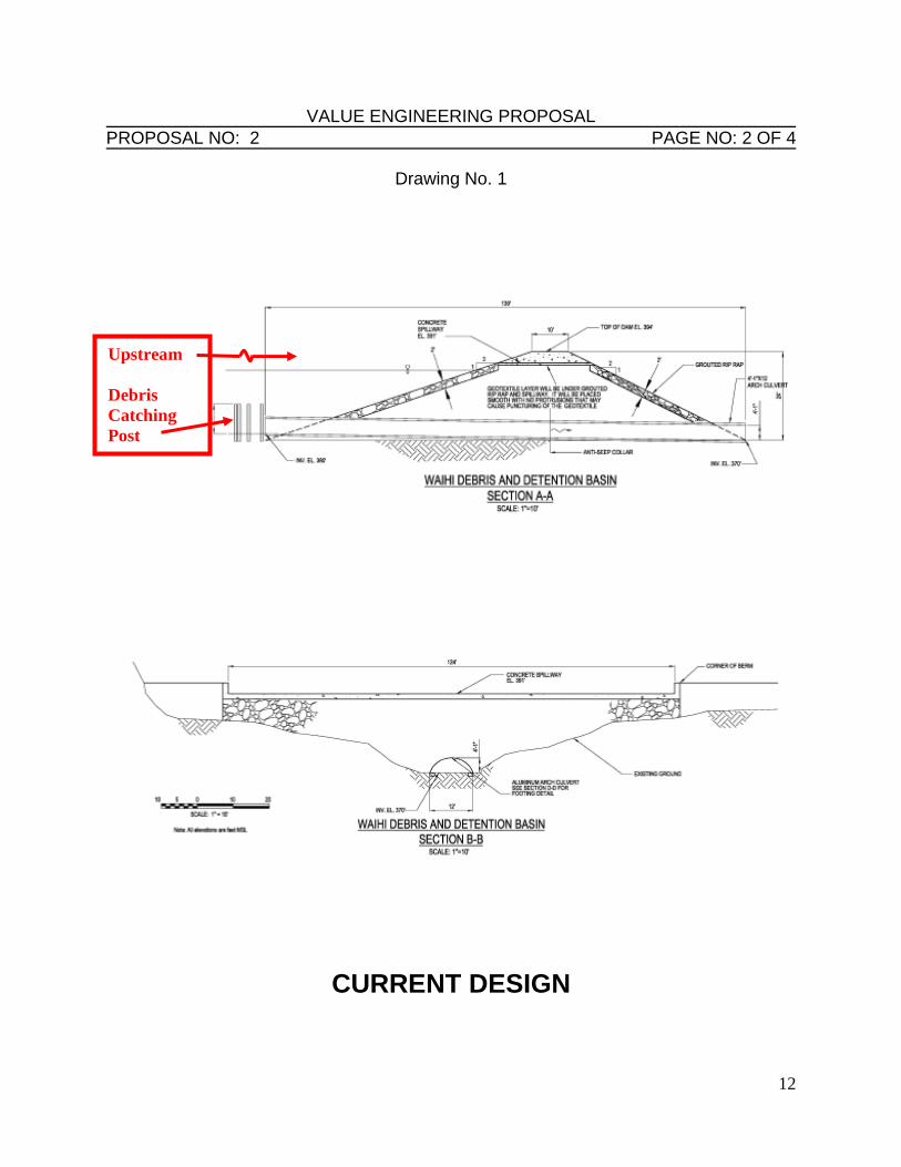
DESCRIPTION: Provide concrete pad in the detention basin for O&M cleaning. ORIGINAL DESIGN:
Original design does not have a concrete pad for equipment access.
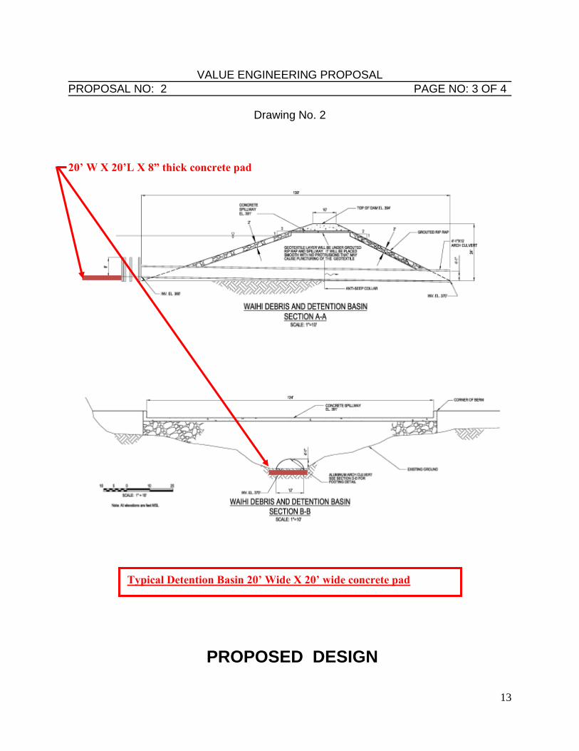
PROPOSED DESIGN:
Add a 20 ft X 20 ft wide concrete pad adjacent to the debris catching post.
ADVANTAGES:
Provides smooth area for equipment such as a dozer to remove debris and sediment.
DISADVANTAGES:
1. Disrupts low flow natural channel for fish passage by hardening the area near the basin.
2. Additional de-watering in the area to form and pour the concrete slab.
3. Could increase stream velocity in the location.
JUSTIFICATION:
This proposal meets the functional requirements of the project at a reduced first cost.
MUTUALLY EXCLUSIVE:
N/A.
12
VALUE ENGINEERING PROPOSAL PROPOSAL NO: 2 PAGE NO: 2 OF 4
Drawing No. 1
CURRENT DESIGN
Upstream
Debris
Catching
Post
13
VALUE ENGINEERING PROPOSAL PROPOSAL NO: 2 PAGE NO: 3 OF 4
Drawing No. 2
20’ W X 20’L X 8” thick concrete pad
PROPOSED DESIGN
Typical Detention Basin 20’ Wide X 20’ wide concrete pad
14
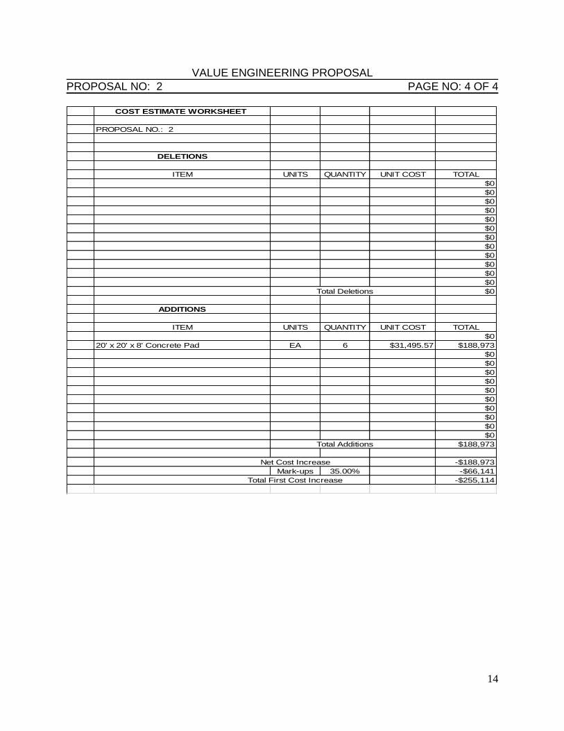
VALUE ENGINEERING PROPOSAL PROPOSAL NO: 2 PAGE NO: 4 OF 4
COST ESTIMATE WORKSHEET
PROPOSAL NO.: 2
DELETIONS
ITEM UNITS QUANTITY UNIT COST TOTAL
$0
$0
$0
$0
$0
$0
$0
$0
$0
$0
$0
$0
Total Deletions $0
ADDITIONS
ITEM UNITS QUANTITY UNIT COST TOTAL
$0
20' x 20' x 8' Concrete Pad EA 6 $31,495.57 $188,973
$0
$0
$0
$0
$0
$0
$0
$0
$0
$0
Total Additions $188,973
Net Cost Increase -$188,973
Mark-ups 35.00% -$66,141
Total First Cost Increase -$255,114
15
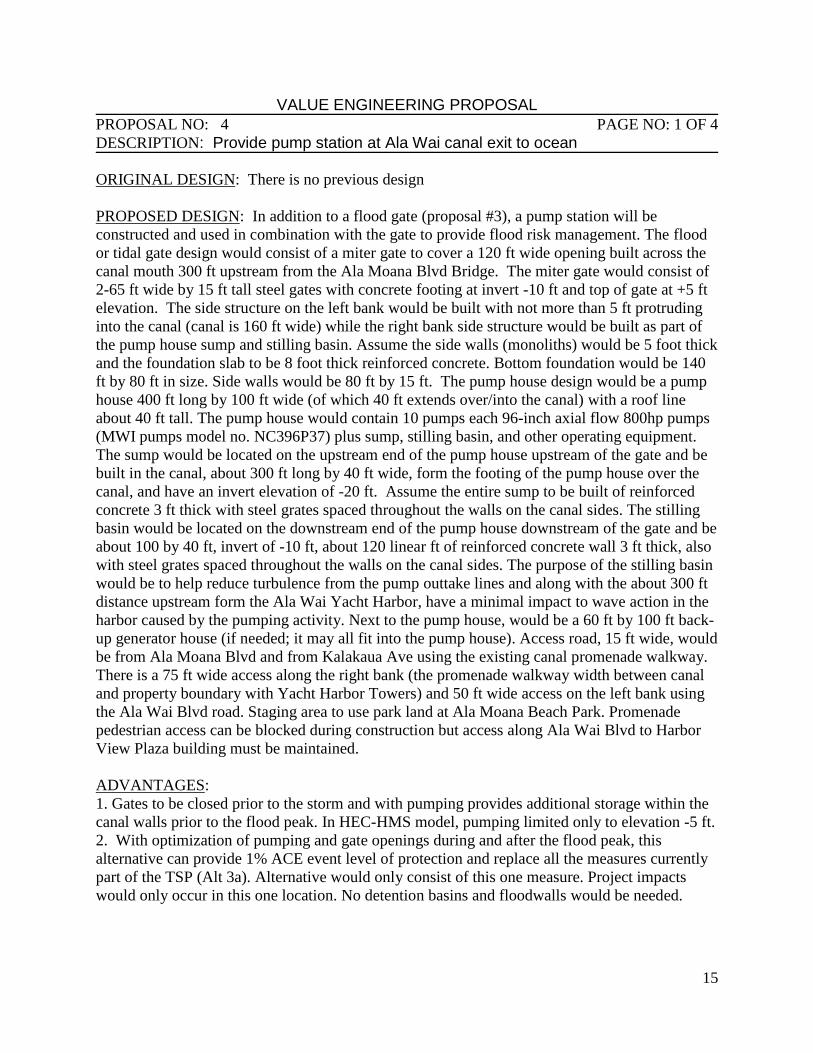
VALUE ENGINEERING PROPOSAL PROPOSAL NO: 4 PAGE NO: 1 OF 4
DESCRIPTION: Provide pump station at Ala Wai canal exit to ocean ORIGINAL DESIGN: There is no previous design
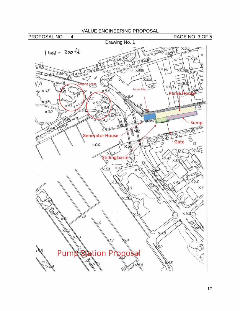
PROPOSED DESIGN: In addition to a flood gate (proposal #3), a pump station will be
constructed and used in combination with the gate to provide flood risk management. The flood
or tidal gate design would consist of a miter gate to cover a 120 ft wide opening built across the
canal mouth 300 ft upstream from the Ala Moana Blvd Bridge. The miter gate would consist of
2-65 ft wide by 15 ft tall steel gates with concrete footing at invert -10 ft and top of gate at +5 ft
elevation. The side structure on the left bank would be built with not more than 5 ft protruding
into the canal (canal is 160 ft wide) while the right bank side structure would be built as part of
the pump house sump and stilling basin. Assume the side walls (monoliths) would be 5 foot thick
and the foundation slab to be 8 foot thick reinforced concrete. Bottom foundation would be 140
ft by 80 ft in size. Side walls would be 80 ft by 15 ft. The pump house design would be a pump
house 400 ft long by 100 ft wide (of which 40 ft extends over/into the canal) with a roof line
about 40 ft tall. The pump house would contain 10 pumps each 96-inch axial flow 800hp pumps
(MWI pumps model no. NC396P37) plus sump, stilling basin, and other operating equipment.
The sump would be located on the upstream end of the pump house upstream of the gate and be
built in the canal, about 300 ft long by 40 ft wide, form the footing of the pump house over the
canal, and have an invert elevation of -20 ft. Assume the entire sump to be built of reinforced
concrete 3 ft thick with steel grates spaced throughout the walls on the canal sides. The stilling
basin would be located on the downstream end of the pump house downstream of the gate and be
about 100 by 40 ft, invert of -10 ft, about 120 linear ft of reinforced concrete wall 3 ft thick, also
with steel grates spaced throughout the walls on the canal sides. The purpose of the stilling basin
would be to help reduce turbulence from the pump outtake lines and along with the about 300 ft
distance upstream form the Ala Wai Yacht Harbor, have a minimal impact to wave action in the
harbor caused by the pumping activity. Next to the pump house, would be a 60 ft by 100 ft back-
up generator house (if needed; it may all fit into the pump house). Access road, 15 ft wide, would
be from Ala Moana Blvd and from Kalakaua Ave using the existing canal promenade walkway.
There is a 75 ft wide access along the right bank (the promenade walkway width between canal
and property boundary with Yacht Harbor Towers) and 50 ft wide access on the left bank using
the Ala Wai Blvd road. Staging area to use park land at Ala Moana Beach Park. Promenade
pedestrian access can be blocked during construction but access along Ala Wai Blvd to Harbor
View Plaza building must be maintained.
ADVANTAGES:
1. Gates to be closed prior to the storm and with pumping provides additional storage within the
canal walls prior to the flood peak. In HEC-HMS model, pumping limited only to elevation -5 ft.
2. With optimization of pumping and gate openings during and after the flood peak, this
alternative can provide 1% ACE event level of protection and replace all the measures currently
part of the TSP (Alt 3a). Alternative would only consist of this one measure. Project impacts
would only occur in this one location. No detention basins and floodwalls would be needed.
16
VALUE ENGINEERING PROPOSAL PROPOSAL NO: 4 PAGE NO: 2 OF 5
DESCRIPTION: Provide pump station at Ala Wai canal exit to ocean DISADVANTAGES:
1. Changes the canal ecosystem during large storm events. By shutting out tidal influence and
pumping out canal and then having canal fill with flood runoff (freshwater) before mixing again
with ocean water when gates are opened would result in killing of fish species. Although most
fish and other aquatic species in canal are mostly invasive species, the rapid mixing of ocean and
freshwater would create ecosystem havoc. Some floating runoff debris and dead fish would be
released into the small boat harbor even with floating trash boom in place. The rapid mixing
would also result in density currents mobilizing bottom sediments into and out of the canal.
These sediments could have an impact to the yacht harbor and near ocean environment.
2. Location of pump house near residential apartments (Yacht Harbor Towers) would result in
noise issues to residents when pumps are running. Noise abatement in structure is needed.
3. Gate and pump house structures to impact view-plane along canal between Ala Moana Blvd
and Kalakaua Ave.
4. Gate and pump house structures to impact recreational uses, canoes, kayaks, and small boats,
when gates are closed and pumps are turned on.
5. Gate opening during and after peak flow event may create turbulence or unwanted currents
into yacht harbor.
JUSTIFICATION:
This proposal meets the functional requirements of the project at a reduced first cost.
MUTUALLY EXCLUSIVE:
N/A
17
VALUE ENGINEERING PROPOSAL PROPOSAL NO: 4 PAGE NO: 3 OF 5
Drawing No. 1
18
VALUE ENGINEERING PROPOSAL PROPOSAL NO: 4 PAGE NO: 4 OF 7
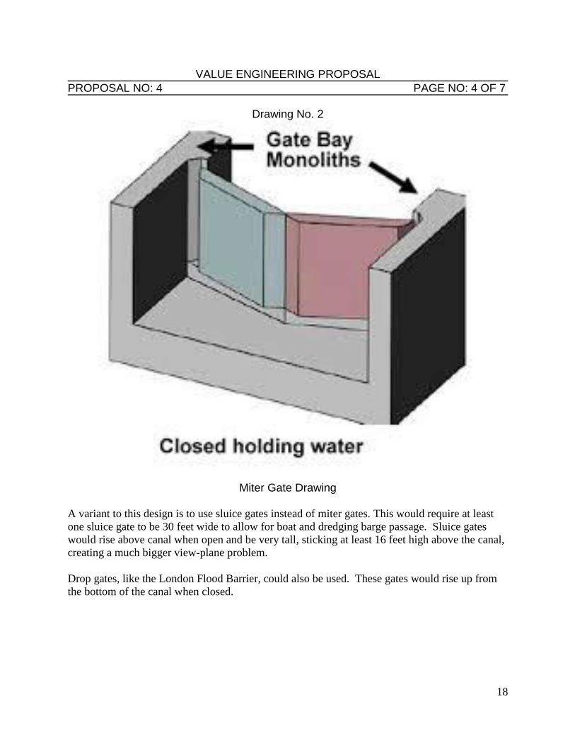
Drawing No. 2
Miter Gate Drawing A variant to this design is to use sluice gates instead of miter gates. This would require at least
one sluice gate to be 30 feet wide to allow for boat and dredging barge passage. Sluice gates
would rise above canal when open and be very tall, sticking at least 16 feet high above the canal,
creating a much bigger view-plane problem.
Drop gates, like the London Flood Barrier, could also be used. These gates would rise up from
the bottom of the canal when closed.
19
VALUE ENGINEERING PROPOSAL
PROPOSAL NO: 4 PAGE NO: 5 OF 7
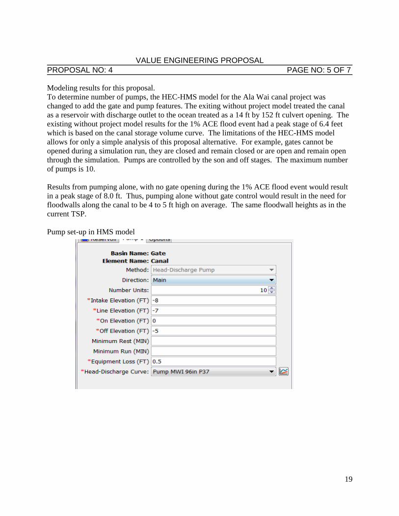
Modeling results for this proposal.
To determine number of pumps, the HEC-HMS model for the Ala Wai canal project was
changed to add the gate and pump features. The exiting without project model treated the canal
as a reservoir with discharge outlet to the ocean treated as a 14 ft by 152 ft culvert opening. The
existing without project model results for the 1% ACE flood event had a peak stage of 6.4 feet
which is based on the canal storage volume curve. The limitations of the HEC-HMS model
allows for only a simple analysis of this proposal alternative. For example, gates cannot be
opened during a simulation run, they are closed and remain closed or are open and remain open
through the simulation. Pumps are controlled by the son and off stages. The maximum number
of pumps is 10.
Results from pumping alone, with no gate opening during the 1% ACE flood event would result
in a peak stage of 8.0 ft. Thus, pumping alone without gate control would result in the need for
floodwalls along the canal to be 4 to 5 ft high on average. The same floodwall heights as in the
current TSP.
Pump set-up in HMS model
20
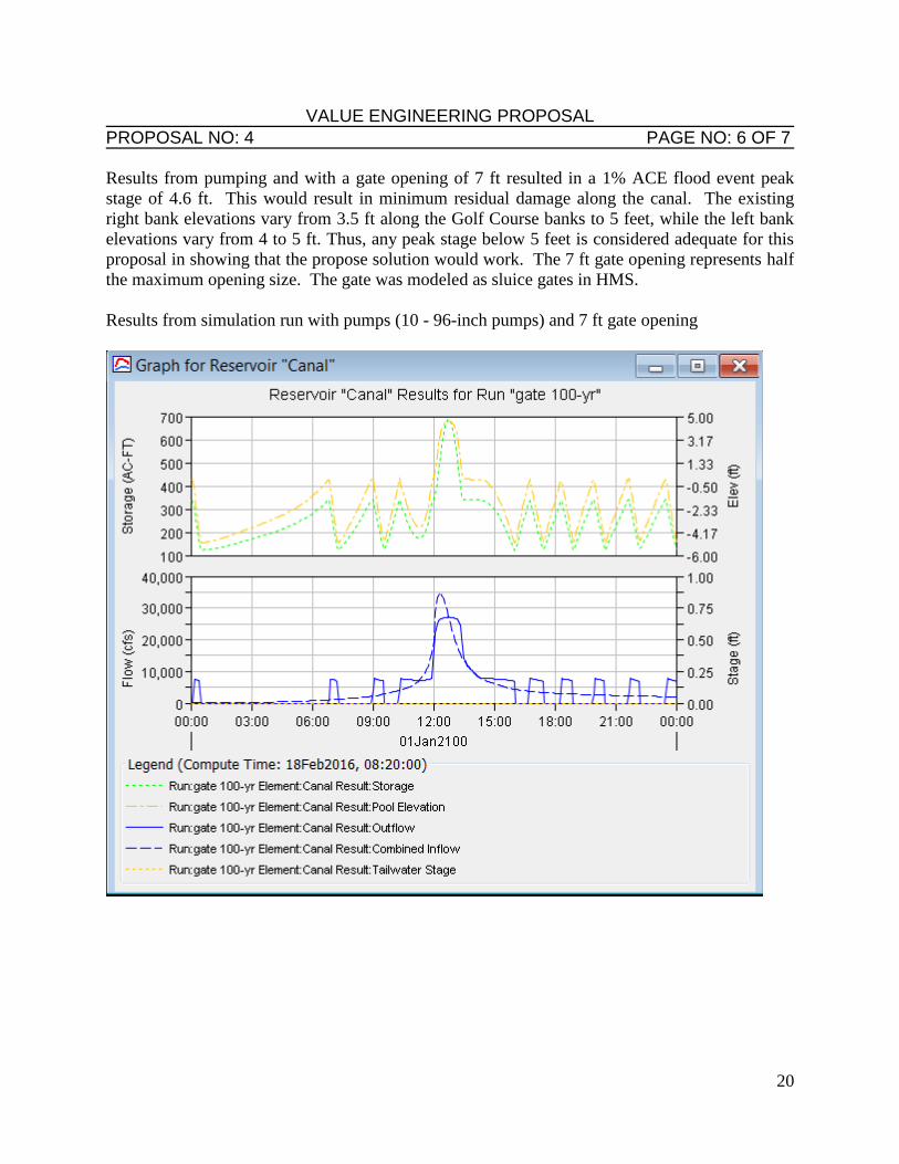
VALUE ENGINEERING PROPOSAL PROPOSAL NO: 4 PAGE NO: 6 OF 7
Results from pumping and with a gate opening of 7 ft resulted in a 1% ACE flood event peak
stage of 4.6 ft. This would result in minimum residual damage along the canal. The existing
right bank elevations vary from 3.5 ft along the Golf Course banks to 5 feet, while the left bank
elevations vary from 4 to 5 ft. Thus, any peak stage below 5 feet is considered adequate for this
proposal in showing that the propose solution would work. The 7 ft gate opening represents half
the maximum opening size. The gate was modeled as sluice gates in HMS.
Results from simulation run with pumps (10 - 96-inch pumps) and 7 ft gate opening
21
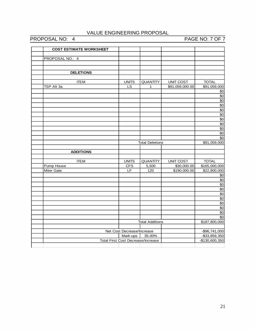
VALUE ENGINEERING PROPOSAL PROPOSAL NO: 4 PAGE NO: 7 OF 7
COST ESTIMATE WORKSHEET
PROPOSAL NO.: 4
DELETIONS
ITEM UNITS QUANTITY UNIT COST TOTAL
TSP Alt 3a LS 1 $91,059,000.00 $91,059,000
$0
$0
$0
$0
$0
$0
$0
$0
$0
$0
$0
Total Deletions $91,059,000
ADDITIONS
ITEM UNITS QUANTITY UNIT COST TOTAL
Pump House CFS 5,500 $30,000.00 $165,000,000
Miter Gate LF 120 $190,000.00 $22,800,000
$0
$0
$0
$0
$0
$0
$0
$0
$0
$0
Total Additions $187,800,000
Net Cost Decrease/Increase -$96,741,000
Mark-ups 35.00% -$33,859,350
Total First Cost Decrease/Increase -$130,600,350
22
VALUE ENGINEERING PROPOSAL PROPOSAL NO: 5 PAGE NO: 1 OF 2
DESCRIPTION: Provide sheet pile walls for all vertical walls.
ORIGINAL DESIGN:
All vertical walls are constructed of concrete in the current design.
PROPOSED DESIGN:
Provide sheet piles in lieu of concrete for all vertical walls.
ADVANTAGES:
1. Reduces cost.
2. Reduces construction time.
DISADVANTAGES:
1. Increased maintenance.
2. Reduced life cycle.
JUSTIFICATION:
This proposal meets the functional requirements of the project at a reduced first cost.
MUTUALLY EXCLUSIVE:
N/A.
23
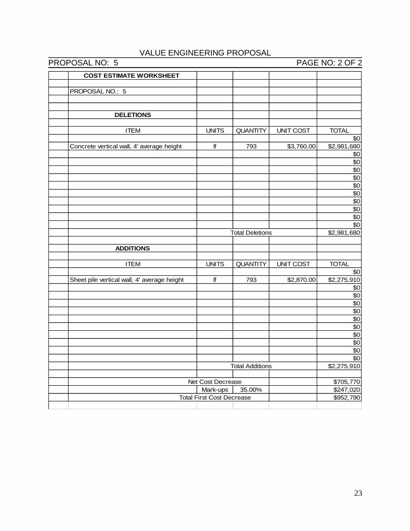
VALUE ENGINEERING PROPOSAL PROPOSAL NO: 5 PAGE NO: 2 OF 2
COST ESTIMATE WORKSHEET
PROPOSAL NO.: 5
DELETIONS
ITEM UNITS QUANTITY UNIT COST TOTAL
$0
Concrete vertical wall, 4' average height lf 793 $3,760.00 $2,981,680
$0
$0
$0
$0
$0
$0
$0
$0
$0
$0
Total Deletions $2,981,680
ADDITIONS
ITEM UNITS QUANTITY UNIT COST TOTAL
$0
Sheet pile vertical wall, 4' average height lf 793 $2,870.00 $2,275,910
$0
$0
$0
$0
$0
$0
$0
$0
$0
$0
Total Additions $2,275,910
Net Cost Decrease $705,770
Mark-ups 35.00% $247,020
Total First Cost Decrease $952,790
24
VALUE ENGINEERING PROPOSAL PROPOSAL NO: 6 PAGE NO: 1 OF 2
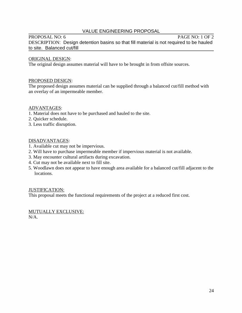
DESCRIPTION: Design detention basins so that fill material is not required to be hauled to site. Balanced cut/fill ORIGINAL DESIGN:
The original design assumes material will have to be brought in from offsite sources.
PROPOSED DESIGN:
The proposed design assumes material can be supplied through a balanced cut/fill method with
an overlay of an impermeable member.
ADVANTAGES:
1. Material does not have to be purchased and hauled to the site.
2. Quicker schedule.
3. Less traffic disruption.
DISADVANTAGES:
1. Available cut may not be impervious.
2. Will have to purchase impermeable member if impervious material is not available.
3. May encounter cultural artifacts during excavation.
4. Cut may not be available next to fill site.
5. Woodlawn does not appear to have enough area available for a balanced cut/fill adjacent to the
locations.
JUSTIFICATION:
This proposal meets the functional requirements of the project at a reduced first cost.
MUTUALLY EXCLUSIVE:
N/A.
25
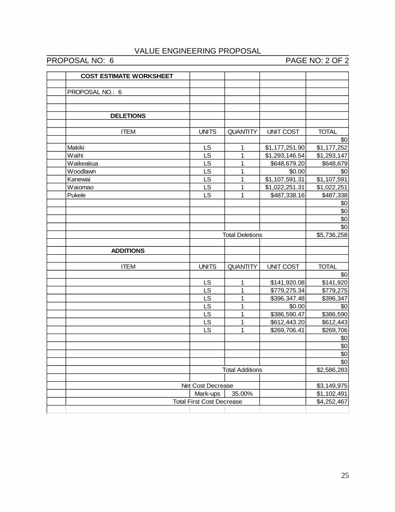
VALUE ENGINEERING PROPOSAL PROPOSAL NO: 6 PAGE NO: 2 OF 2
COST ESTIMATE WORKSHEET
PROPOSAL NO.: 6
DELETIONS
ITEM UNITS QUANTITY UNIT COST TOTAL
$0
Makiki LS 1 $1,177,251.90 $1,177,252
Waihi LS 1 $1,293,146.54 $1,293,147
Waikeakua LS 1 $648,679.20 $648,679
Woodlawn LS 1 $0.00 $0
Kanewai LS 1 $1,107,591.31 $1,107,591
Waiomao LS 1 $1,022,251.31 $1,022,251
Pukele LS 1 $487,338.16 $487,338
$0
$0
$0
$0
Total Deletions $5,736,258
ADDITIONS
ITEM UNITS QUANTITY UNIT COST TOTAL
$0
LS 1 $141,920.08 $141,920
LS 1 $779,275.34 $779,275
LS 1 $396,347.48 $396,347
LS 1 $0.00 $0
LS 1 $386,590.47 $386,590
LS 1 $612,443.20 $612,443
LS 1 $269,706.41 $269,706
$0
$0
$0
$0
Total Additions $2,586,283
Net Cost Decrease $3,149,975
Mark-ups 35.00% $1,102,491
Total First Cost Decrease $4,252,467
26
VALUE ENGINEERING PROPOSAL PROPOSAL NO: 10 PAGE NO: 1 OF 4
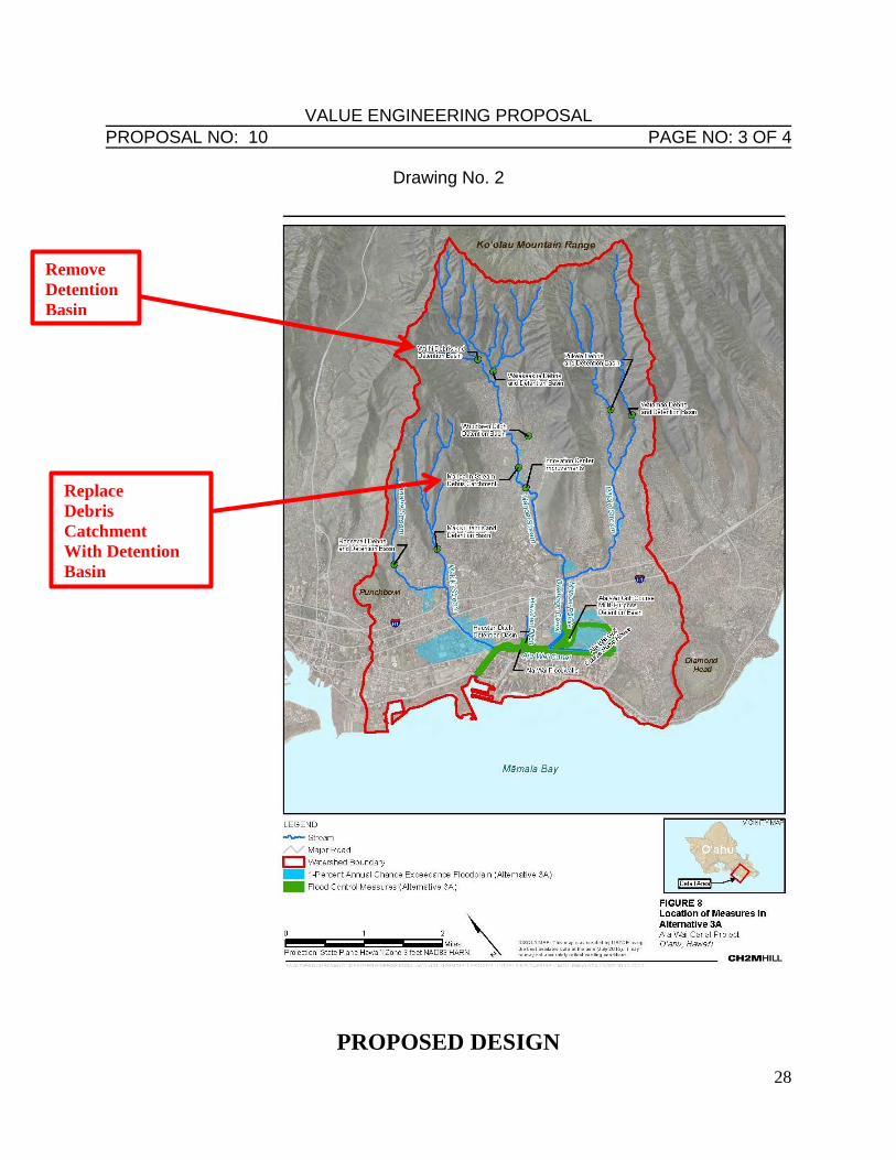
DESCRIPTION: Revisit using Manoa Park as a multipurpose site for debris catchment and
detention
ORIGINAL DESIGN: Manoa Park site was screened out of the initial plan formulation
PROPOSED DESIGN: Integrate Manoa Park in lieu of utilizing either Waihi or Waiakeakua
basins.
ADVANTAGES:
1. Avoid Endangered Species Act impacts
2. Similar costs (???)
DISADVANTAGES:
1. Loss of park use
2. Increased residual damages upstream of Manoa Park
3. Requires reevaluation of economics
JUSTIFICATION:
This proposal meets the functional requirements of the project at a reduced first cost.
MUTUALLY EXCLUSIVE:
N/A.
27
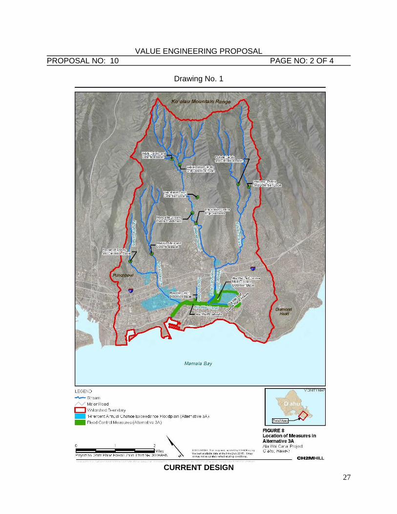
VALUE ENGINEERING PROPOSAL PROPOSAL NO: 10 PAGE NO: 2 OF 4
Drawing No. 1
CURRENT DESIGN
28
VALUE ENGINEERING PROPOSAL PROPOSAL NO: 10 PAGE NO: 3 OF 4
Drawing No. 2
PROPOSED DESIGN
Remove
Detention
Basin
Replace
Debris
Catchment
With Detention
Basin
29
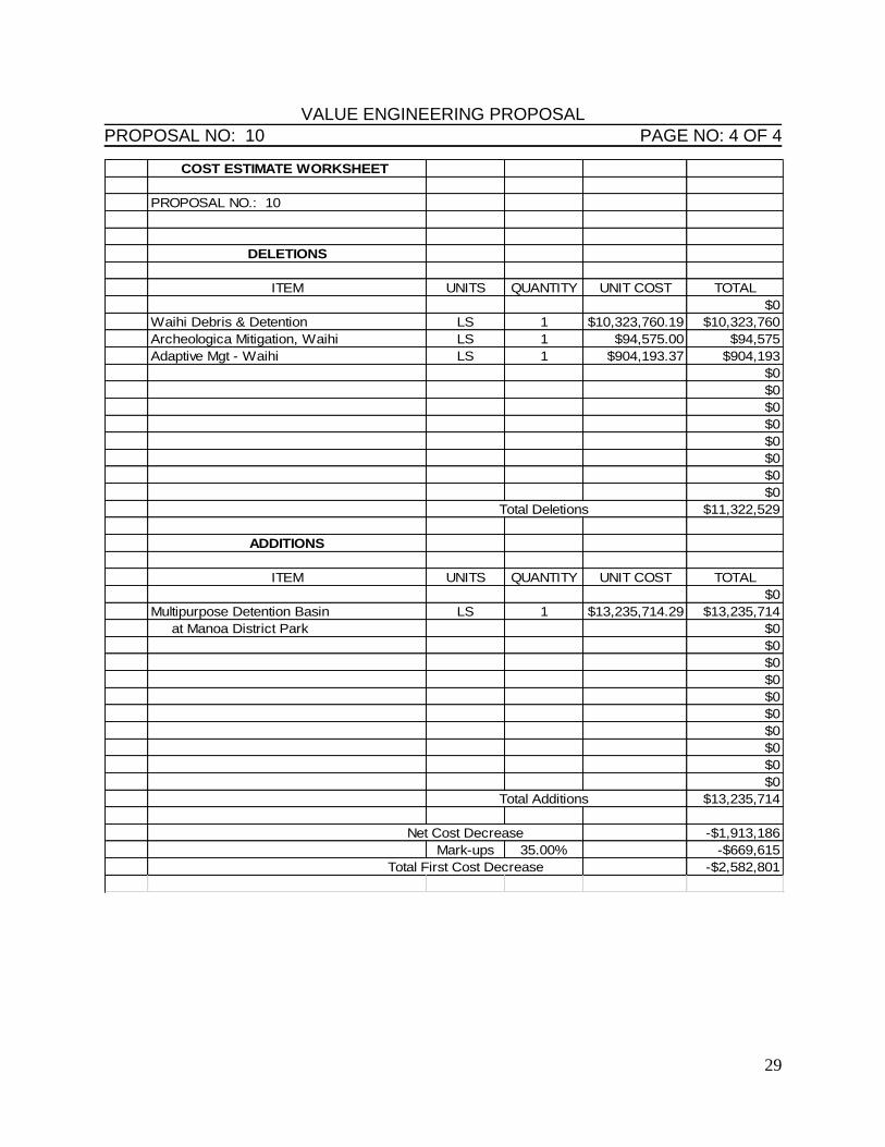
VALUE ENGINEERING PROPOSAL PROPOSAL NO: 10 PAGE NO: 4 OF 4
COST ESTIMATE WORKSHEET
PROPOSAL NO.: 10
DELETIONS
ITEM UNITS QUANTITY UNIT COST TOTAL
$0
Waihi Debris & Detention LS 1 $10,323,760.19 $10,323,760
Archeologica Mitigation, Waihi LS 1 $94,575.00 $94,575
Adaptive Mgt - Waihi LS 1 $904,193.37 $904,193
$0
$0
$0
$0
$0
$0
$0
$0
Total Deletions $11,322,529
ADDITIONS
ITEM UNITS QUANTITY UNIT COST TOTAL
$0
Multipurpose Detention Basin LS 1 $13,235,714.29 $13,235,714
at Manoa District Park $0
$0
$0
$0
$0
$0
$0
$0
$0
$0
Total Additions $13,235,714
Net Cost Decrease -$1,913,186
Mark-ups 35.00% -$669,615
Total First Cost Decrease -$2,582,801
30
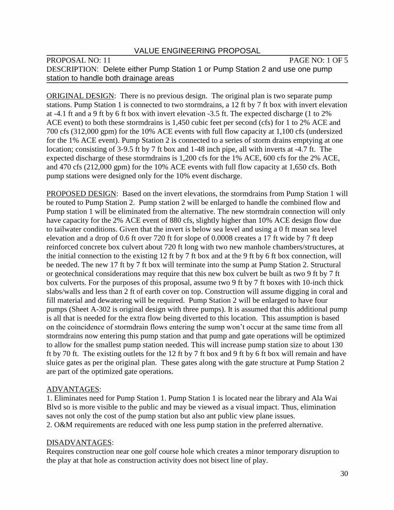
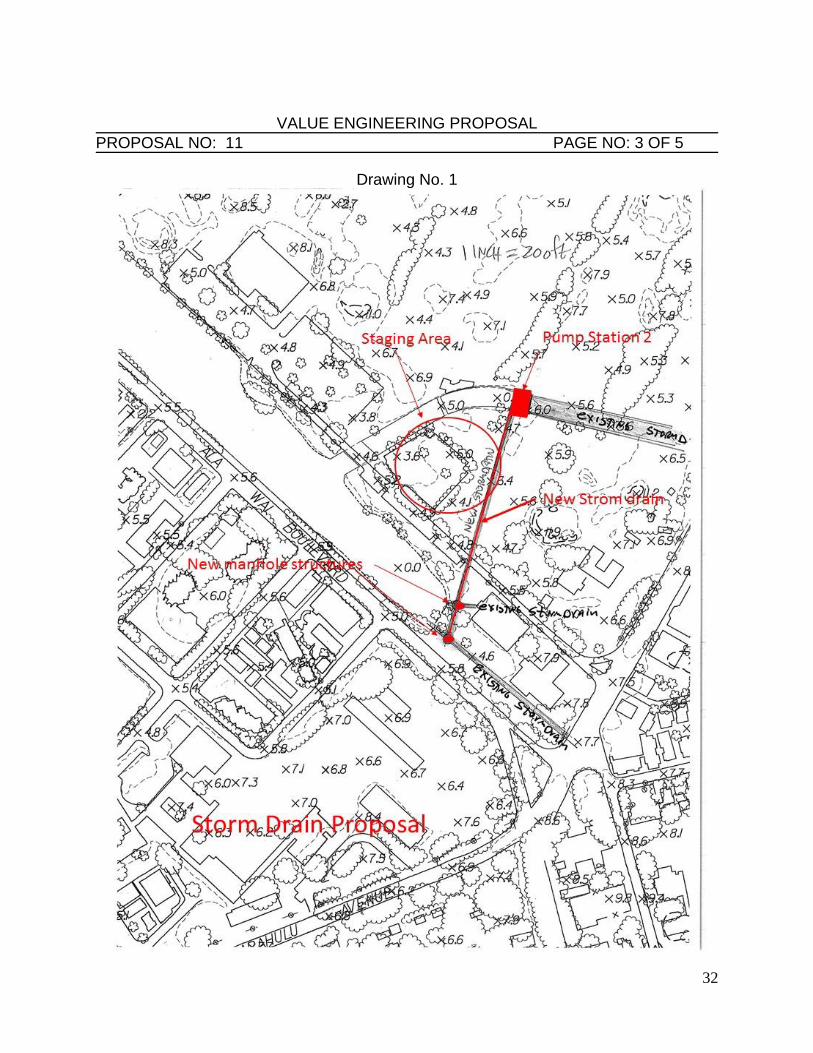
VALUE ENGINEERING PROPOSAL PROPOSAL NO: 11 PAGE NO: 1 OF 5
DESCRIPTION: Delete either Pump Station 1 or Pump Station 2 and use one pump station to handle both drainage areas ORIGINAL DESIGN: There is no previous design. The original plan is two separate pump
stations. Pump Station 1 is connected to two stormdrains, a 12 ft by 7 ft box with invert elevation
at -4.1 ft and a 9 ft by 6 ft box with invert elevation -3.5 ft. The expected discharge (1 to 2%
ACE event) to both these stormdrains is 1,450 cubic feet per second (cfs) for 1 to 2% ACE and
700 cfs (312,000 gpm) for the 10% ACE events with full flow capacity at 1,100 cfs (undersized
for the 1% ACE event). Pump Station 2 is connected to a series of storm drains emptying at one
location; consisting of 3-9.5 ft by 7 ft box and 1-48 inch pipe, all with inverts at -4.7 ft. The
expected discharge of these stormdrains is 1,200 cfs for the 1% ACE, 600 cfs for the 2% ACE,
and 470 cfs (212,000 gpm) for the 10% ACE events with full flow capacity at 1,650 cfs. Both
pump stations were designed only for the 10% event discharge.
PROPOSED DESIGN: Based on the invert elevations, the stormdrains from Pump Station 1 will
be routed to Pump Station 2. Pump station 2 will be enlarged to handle the combined flow and
Pump station 1 will be eliminated from the alternative. The new stormdrain connection will only
have capacity for the 2% ACE event of 880 cfs, slightly higher than 10% ACE design flow due
to tailwater conditions. Given that the invert is below sea level and using a 0 ft mean sea level
elevation and a drop of 0.6 ft over 720 ft for slope of 0.0008 creates a 17 ft wide by 7 ft deep
reinforced concrete box culvert about 720 ft long with two new manhole chambers/structures, at
the initial connection to the existing 12 ft by 7 ft box and at the 9 ft by 6 ft box connection, will
be needed. The new 17 ft by 7 ft box will terminate into the sump at Pump Station 2. Structural
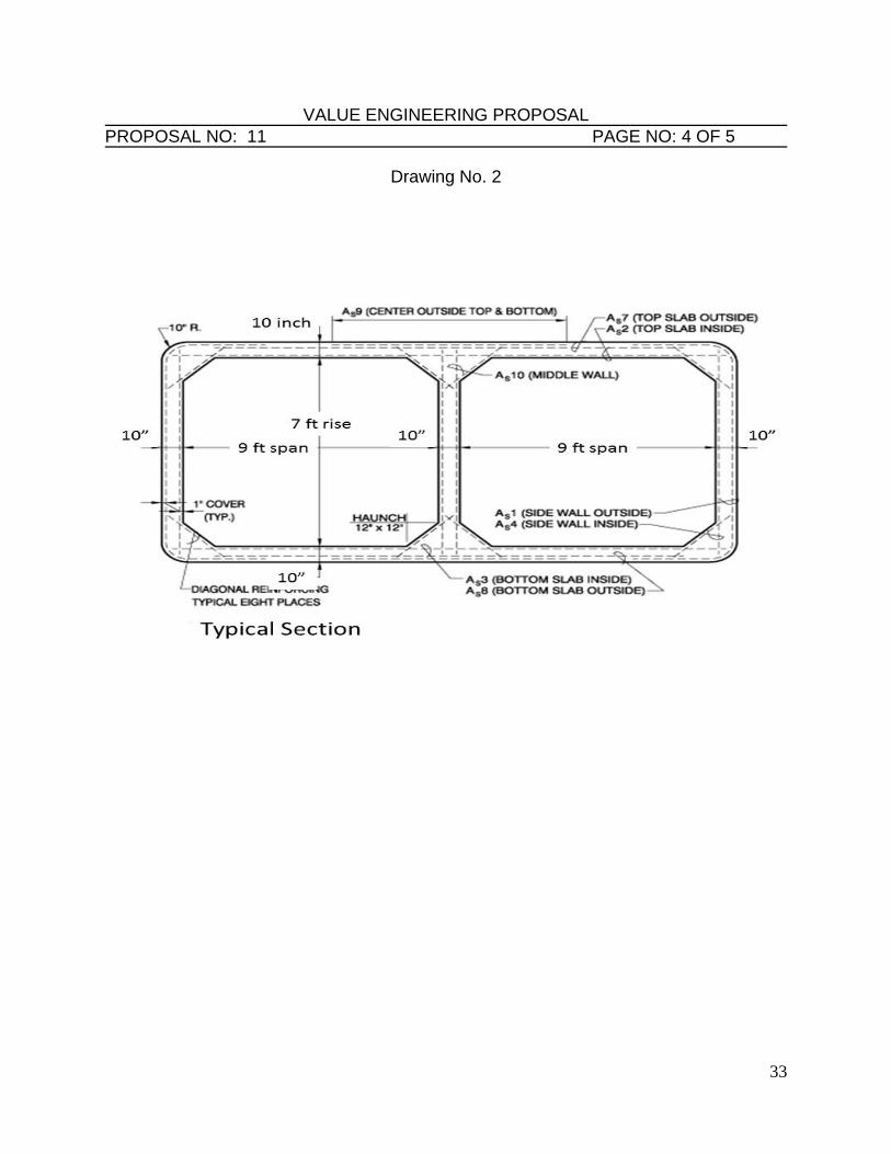
or geotechnical considerations may require that this new box culvert be built as two 9 ft by 7 ft
box culverts. For the purposes of this proposal, assume two 9 ft by 7 ft boxes with 10-inch thick
slabs/walls and less than 2 ft of earth cover on top. Construction will assume digging in coral and
fill material and dewatering will be required. Pump Station 2 will be enlarged to have four
pumps (Sheet A-302 is original design with three pumps). It is assumed that this additional pump
is all that is needed for the extra flow being diverted to this location. This assumption is based
on the coincidence of stormdrain flows entering the sump won’t occur at the same time from all
stormdrains now entering this pump station and that pump and gate operations will be optimized
to allow for the smallest pump station needed. This will increase pump station size to about 130
ft by 70 ft. The existing outlets for the 12 ft by 7 ft box and 9 ft by 6 ft box will remain and have
sluice gates as per the original plan. These gates along with the gate structure at Pump Station 2
are part of the optimized gate operations.
ADVANTAGES:
1. Eliminates need for Pump Station 1. Pump Station 1 is located near the library and Ala Wai
Blvd so is more visible to the public and may be viewed as a visual impact. Thus, elimination
saves not only the cost of the pump station but also ant public view plane issues.
2. O&M requirements are reduced with one less pump station in the preferred alternative.
DISADVANTAGES:
Requires construction near one golf course hole which creates a minor temporary disruption to
the play at that hole as construction activity does not bisect line of play.
31
VALUE ENGINEERING PROPOSAL PROPOSAL NO: 11 PAGE NO: 2 OF 5
JUSTIFICATION:
This proposal meets the functional requirements of the project at a reduced first cost.
MUTUALLY EXCLUSIVE:
N/A.
32
VALUE ENGINEERING PROPOSAL PROPOSAL NO: 11 PAGE NO: 3 OF 5
Drawing No. 1
33
VALUE ENGINEERING PROPOSAL PROPOSAL NO: 11 PAGE NO: 4 OF 5
Drawing No. 2
34
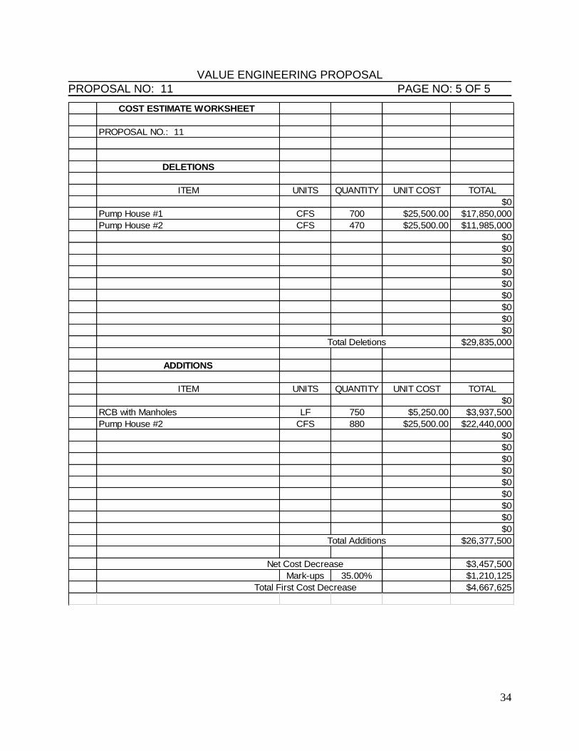
VALUE ENGINEERING PROPOSAL PROPOSAL NO: 11 PAGE NO: 5 OF 5
COST ESTIMATE WORKSHEET
PROPOSAL NO.: 11
DELETIONS
ITEM UNITS QUANTITY UNIT COST TOTAL
$0
Pump House #1 CFS 700 $25,500.00 $17,850,000
Pump House #2 CFS 470 $25,500.00 $11,985,000
$0
$0
$0
$0
$0
$0
$0
$0
$0
Total Deletions $29,835,000
ADDITIONS
ITEM UNITS QUANTITY UNIT COST TOTAL
$0
RCB with Manholes LF 750 $5,250.00 $3,937,500
Pump House #2 CFS 880 $25,500.00 $22,440,000
$0
$0
$0
$0
$0
$0
$0
$0
$0
Total Additions $26,377,500
Net Cost Decrease $3,457,500
Mark-ups 35.00% $1,210,125
Total First Cost Decrease $4,667,625
35
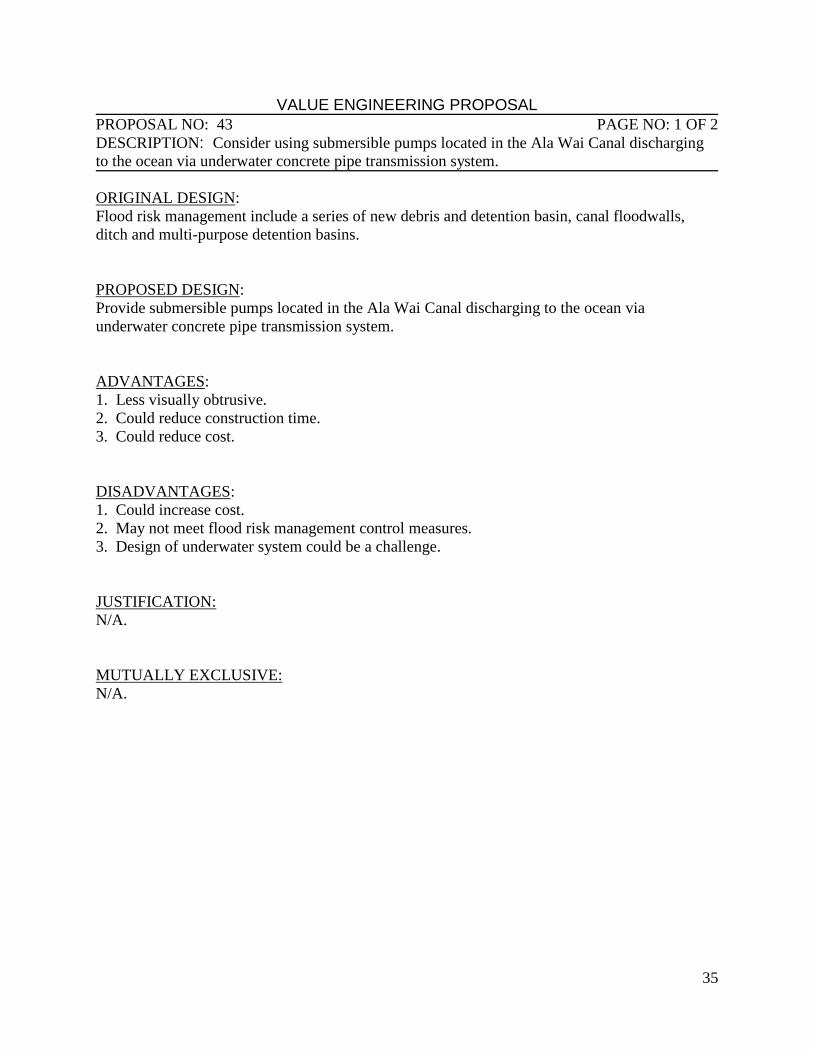
VALUE ENGINEERING PROPOSAL PROPOSAL NO: 43 PAGE NO: 1 OF 2
DESCRIPTION: Consider using submersible pumps located in the Ala Wai Canal discharging
to the ocean via underwater concrete pipe transmission system.
ORIGINAL DESIGN:
Flood risk management include a series of new debris and detention basin, canal floodwalls,
ditch and multi-purpose detention basins.
PROPOSED DESIGN:
Provide submersible pumps located in the Ala Wai Canal discharging to the ocean via
underwater concrete pipe transmission system.
ADVANTAGES:
1. Less visually obtrusive.
2. Could reduce construction time.
3. Could reduce cost.
DISADVANTAGES:
1. Could increase cost.
2. May not meet flood risk management control measures.
3. Design of underwater system could be a challenge.
JUSTIFICATION:
N/A.
MUTUALLY EXCLUSIVE:
N/A.
36
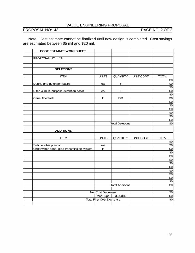
VALUE ENGINEERING PROPOSAL PROPOSAL NO: 43 PAGE NO: 2 OF 2 Note: Cost estimate cannot be finalized until new design is completed. Cost savings are estimated between $5 mil and $20 mil.
COST ESTIMATE WORKSHEET
PROPOSAL NO.: 43
DELETIONS
ITEM UNITS QUANTITY UNIT COST TOTAL
$0
Debris and detention basin ea 5 $0
$0
Ditch & multi-purpose detention basin ea 6 $0
$0
Canal floodwall lf 793 $0
$0
$0
$0
$0
$0
$0
Total Deletions $0
ADDITIONS
ITEM UNITS QUANTITY UNIT COST TOTAL
$0
Submersible pumps ea $0
Underwater conc. pipe transmission system lf $0
$0
$0
$0
$0
$0
$0
$0
$0
$0
Total Additions $0
Net Cost Decrease $0
Mark-ups 35.00% $0
Total First Cost Decrease $0
37
VALUE ENGINEERING COMMENTS
Comment 12. Provide a fence around the detention basins for safety: This suggestion will
probably be incorporated into the design as a safety criteria but it is mentioned because of its
importance to life safety.
Comment 13. Remove vegetation upstream to prevent falling into streams: This
comment is to help address the vegetative debris issue. Debris generation can be
minimized by preventive pruning of vegetation along the streams banks in the watershed.
This prevention then reduces debris for post-flood clean-up and/or any flood problems
such debris may cause during a flood event. Approximately 1.5 miles of stream channel
along Manoa Stream, 1.2 miles along Palolo stream, and 0.3 miles along Makaiki Stream,
would need to be maintained in such a fashion.
Comment 14. Add sandlewood or other vegetation native to the area: This comment
is to help address invasive species vegetation such as Albizia trees which tend to produce
vegetative debris during storms as they have weak branches and root structures and are
prone to fall over or have branches break and fall into streams. Related to Comment 15,
the re-vegetation effort would allow for re-vegetation with native species and species
which do not produce significant woody debris and help with runoff and erosion
reduction. Approximately 200 acres would be re-vegetated in all three valleys, with 100-
125 acres in Manoa Valley, 50-75 acres in Palolo Valley, and 0-25 acres in Makiki
Valley being re-vegetated. These areas would be accessible from current road networks
and would require only limited helicopter support. Approximate cost would be $50,000
per acre.
Comment 15. Provide vegetation that mitigates flooding issues: Similar to Comment
14, this comment is to help address vegetation that can mitigate flood runoff, such as tall
grasses like Vetiver grasses which have deep roots which prevent erosion and help retain
moisture on hillslopes. This would require removal of unwanted vegetative species and
re-vegetation with these types of vegetation. Assume similar acreage as in Comment 14.
Comment 16. Ensure that city ordinance prohibits residents from dumping in
drainage ways: Debris catchment structures are required at detention basins to prevent
blockage to conveyances. A source of this debris is likely homeowners disposing of yard
waste in areas adjacent to waterways. The idea to create a city ordinance to serve as a
deterrent to this practice was brought up, however, it is assumed that the city already
likely has such an ordinance in place.
Comment 17. Revisit capacity of pump stations: Reducing the scale of the pump
stations may result in a reduction in costs. Final hydraulic designs will be completed
during the Feasibility phase which will confirm the capacity required for the pump
stations.
38
Comment 18. Revisit physical size of pump stations: Reducing the physical size of the
pump stations and pump station houses may result in a reduction in costs. Review of the
pump station designs will occur in PED.
Comment 19. Have the State of Hawaii provide a site for disposal of excess excavated
material: Normal practice is to have the construction contractor dispose of excess excavated
material at an approved landfill. This suggestion is to have the excess excavated material
disposed at a site designated by the State of Hawaii. The advantages of this suggestion are that it
would eliminate costly landfill disposal fees and the material could be recycled by the State of
Hawaii at a future project reducing impact to the landfill.
Comment 20. Revisit PED costs: PED costs are currently estimated at approximately
$31million. The methodology for determining these costs was reviewed with the cost
engineer and deemed acceptable, however the scope, schedule and budget for PED will
be developed in detail during that phase of the project and may result in cost savings.
Comment 21. Verify environmental mitigation requirement costs. Environmental mitigation
costs are currently embedded within the cost estimates for project features. The methodology for
determining these costs was reviewed with the cost engineer and deemed acceptable, however
costs will be separated as a separate cost feature in the final estimate. The acceptability to
review agencies of the current mitigation plan is also uncertain may result in cost savings or cost
increases
39
APPENDIX A: CONTACT DIRECTORY
40
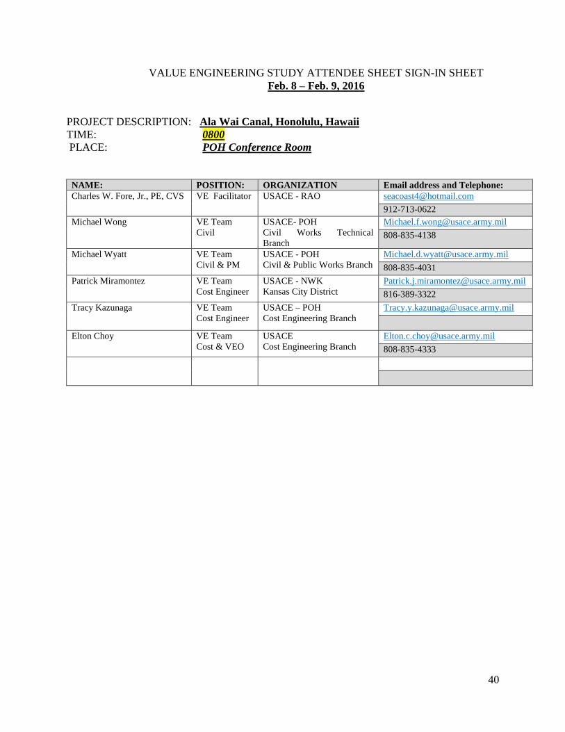
VALUE ENGINEERING STUDY ATTENDEE SHEET SIGN-IN SHEET
Feb. 8 – Feb. 9, 2016
PROJECT DESCRIPTION: Ala Wai Canal, Honolulu, Hawaii
TIME: 0800
PLACE: POH Conference Room
NAME: POSITION: ORGANIZATION Email address and Telephone:
Charles W. Fore, Jr., PE, CVS VE Facilitator USACE - RAO [email protected]
912-713-0622 Michael Wong VE Team
Civil
USACE- POH
Civil Works Technical
Branch
808-835-4138
Michael Wyatt VE Team
Civil & PM
USACE - POH
Civil & Public Works Branch
808-835-4031
Patrick Miramontez VE Team
Cost Engineer
USACE - NWK
Kansas City District
816-389-3322
Tracy Kazunaga VE Team
Cost Engineer
USACE – POH
Cost Engineering Branch
Elton Choy VE Team
Cost & VEO USACE
Cost Engineering Branch [email protected]
808-835-4333

41
APPENDIX B: CREATIVE IDEA LIST
42
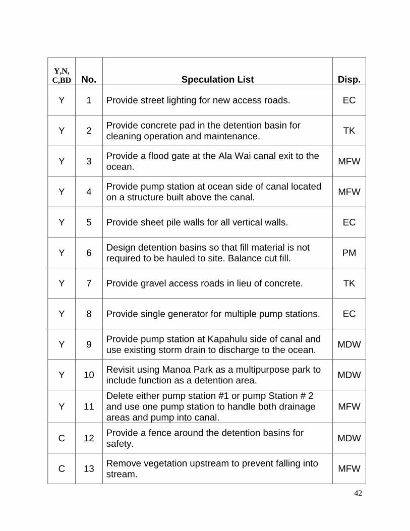
Y,N,
C,BD No. Speculation List Disp.
Y 1 Provide street lighting for new access roads. EC
Y 2 Provide concrete pad in the detention basin for cleaning operation and maintenance.
TK
Y 3 Provide a flood gate at the Ala Wai canal exit to the ocean.
MFW
Y 4 Provide pump station at ocean side of canal located on a structure built above the canal.
MFW
Y 5 Provide sheet pile walls for all vertical walls. EC
Y 6 Design detention basins so that fill material is not required to be hauled to site. Balance cut fill.
PM
Y 7 Provide gravel access roads in lieu of concrete. TK
Y 8 Provide single generator for multiple pump stations. EC
Y 9 Provide pump station at Kapahulu side of canal and use existing storm drain to discharge to the ocean.
MDW
Y 10 Revisit using Manoa Park as a multipurpose park to include function as a detention area.
MDW
Y 11 Delete either pump station #1 or pump Station # 2 and use one pump station to handle both drainage areas and pump into canal.
MFW
C 12 Provide a fence around the detention basins for safety.
MDW
C 13 Remove vegetation upstream to prevent falling into stream.
MFW
43
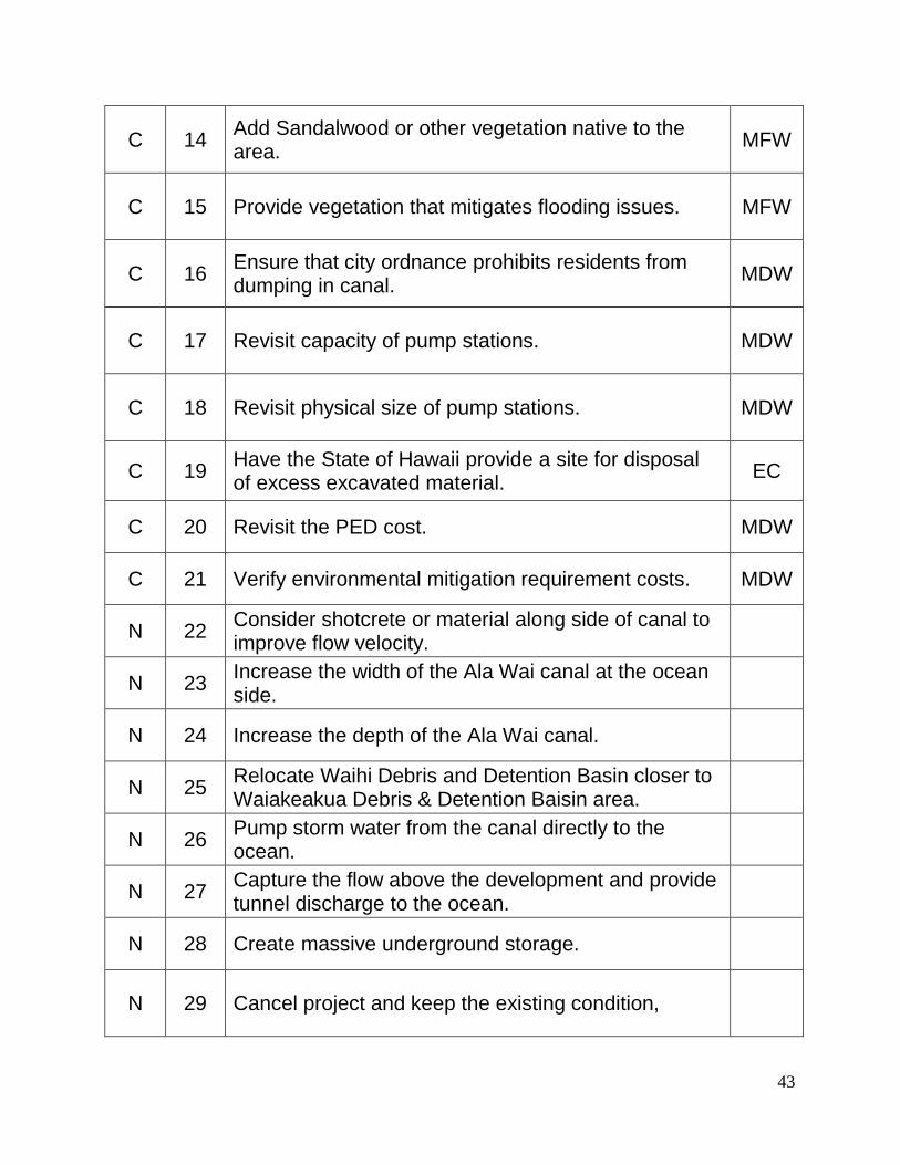
C 14 Add Sandalwood or other vegetation native to the area.
MFW
C 15 Provide vegetation that mitigates flooding issues. MFW
C 16 Ensure that city ordnance prohibits residents from dumping in canal.
MDW
C 17 Revisit capacity of pump stations. MDW
C 18 Revisit physical size of pump stations. MDW
C 19 Have the State of Hawaii provide a site for disposal of excess excavated material.
EC
C 20 Revisit the PED cost. MDW
C 21 Verify environmental mitigation requirement costs. MDW
N 22 Consider shotcrete or material along side of canal to improve flow velocity.
N 23 Increase the width of the Ala Wai canal at the ocean side.
N 24 Increase the depth of the Ala Wai canal.
N 25 Relocate Waihi Debris and Detention Basin closer to Waiakeakua Debris & Detention Baisin area.
N 26 Pump storm water from the canal directly to the ocean.
N 27 Capture the flow above the development and provide tunnel discharge to the ocean.
N 28 Create massive underground storage.
N 29 Cancel project and keep the existing condition,
44
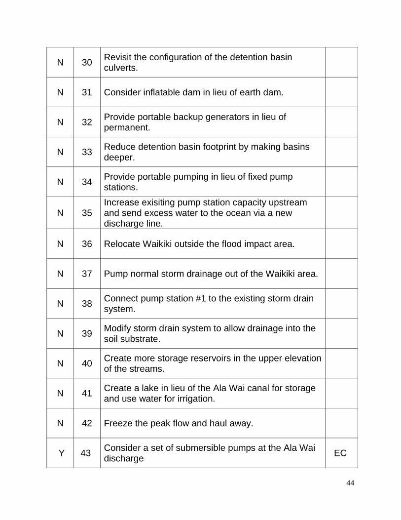
N 30 Revisit the configuration of the detention basin culverts.
N 31 Consider inflatable dam in lieu of earth dam.
N 32 Provide portable backup generators in lieu of permanent.
N 33 Reduce detention basin footprint by making basins deeper.
N 34 Provide portable pumping in lieu of fixed pump stations.
N 35 Increase exisiting pump station capacity upstream and send excess water to the ocean via a new discharge line.
N 36 Relocate Waikiki outside the flood impact area.
N 37 Pump normal storm drainage out of the Waikiki area.
N 38 Connect pump station #1 to the existing storm drain system.
N 39 Modify storm drain system to allow drainage into the soil substrate.
N 40 Create more storage reservoirs in the upper elevation of the streams.
N 41 Create a lake in lieu of the Ala Wai canal for storage and use water for irrigation.
N 42 Freeze the peak flow and haul away.
Y 43 Consider a set of submersible pumps at the Ala Wai discharge
EC
45
Y = Yes
N = No
C = Comment
BD = Being Done
46
APPENDIX C: FAST Diagram
47
48
APPENDIX D: Cost Model
49
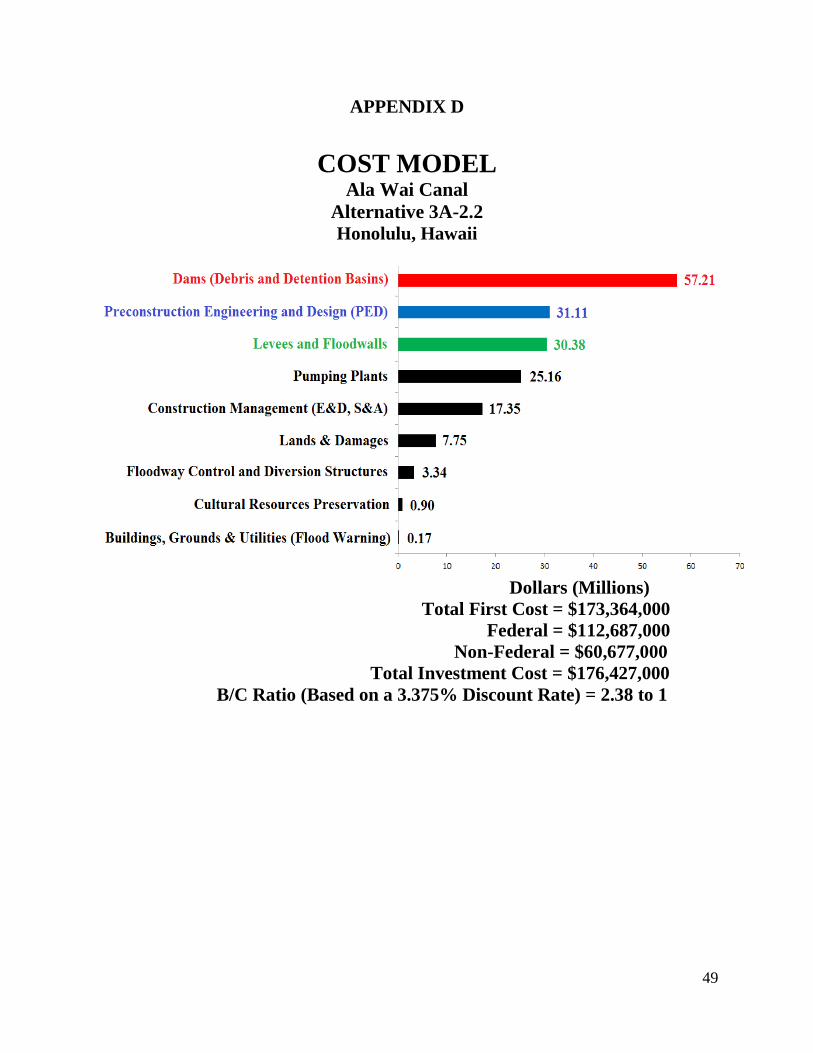
APPENDIX D
COST MODEL
Ala Wai Canal
Alternative 3A-2.2
Honolulu, Hawaii
Dollars (Millions)
Total First Cost = $173,364,000
Federal = $112,687,000
Non-Federal = $60,677,000
Total Investment Cost = $176,427,000
B/C Ratio (Based on a 3.375% Discount Rate) = 2.38 to 1
50
APPENDIX E: Study Schedule
51
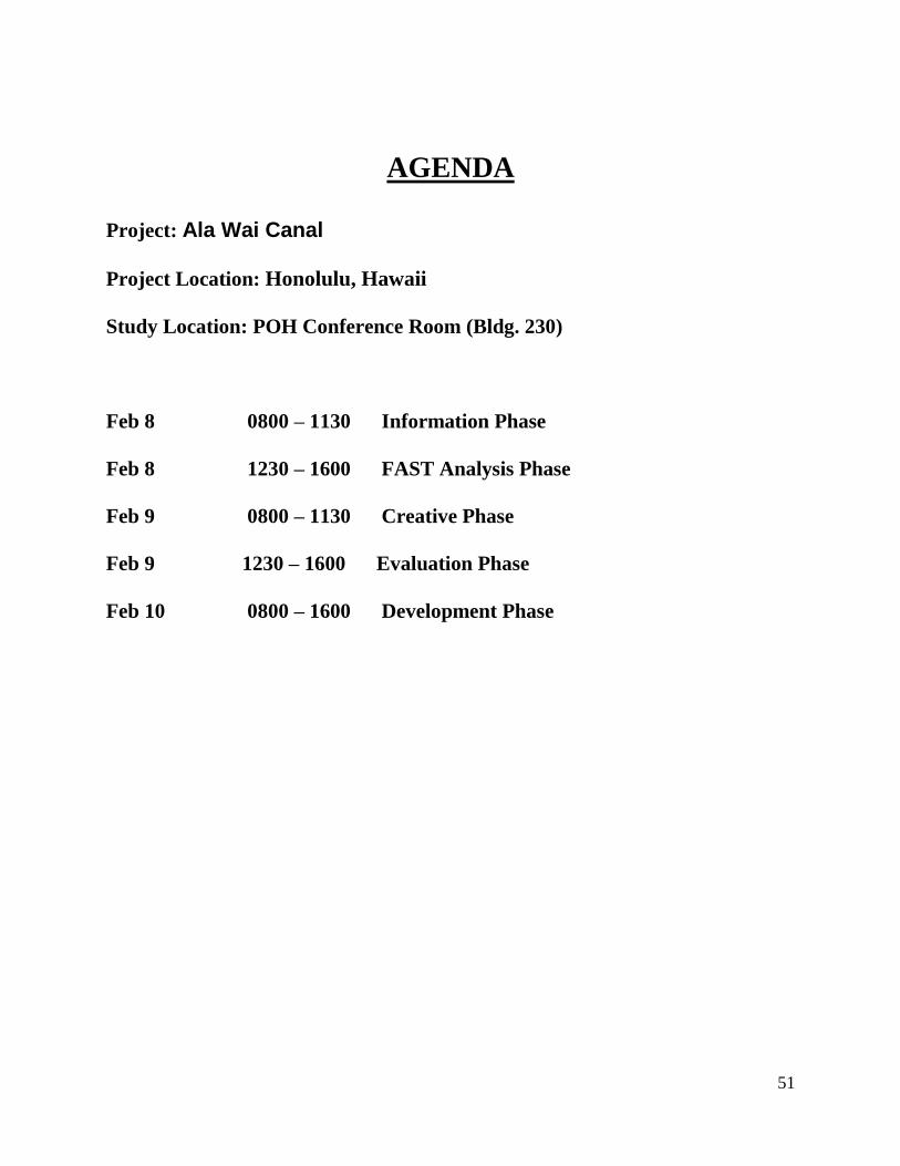
AGENDA
Project: Ala Wai Canal
Project Location: Honolulu, Hawaii
Study Location: POH Conference Room (Bldg. 230)
Feb 8 0800 – 1130 Information Phase
Feb 8 1230 – 1600 FAST Analysis Phase
Feb 9 0800 – 1130 Creative Phase
Feb 9 1230 – 1600 Evaluation Phase
Feb 10 0800 – 1600 Development Phase