Embed Size (px)
Citation preview

INTRODUCTION:
1
www.AriAMetalHardware.com | updated 04/30/2021
ARIA® 1 3/8" R-TEC AUTOMATION® H-RAIL TRAVERSEONE-WAY DRAW SYSTEM INSTALLATION INSTRUCTIONS
Please read all instructions before starting
PARTS LIST:
Basic Components:1. R-TEC Automation® H-Rail Track2. Slim Drapery Motor3. Drive Pulley4. Return Pulley5. Pendant6. Brackets 7. Carriers8. Master Carrier Body & Arms9. Drive Belt10. Drive Belt Clip11. AC Power Transformer power option12. Li-ion Battery power option13. Plain End Caps included; Antiquities Finials sold separately
7
6
8
9
413
7
5
11
12
13
10
2
ONE-WAY BRACKET PLACEMENT:
16" or 24" apartdepending on the
stud positions
48" apart over the remainder of the track
48" apartover the
remainder of the track
48" apartover the
remainder of the track
48" apart over the remainder of the track
16" or 24" apartdepending on the
stud positions
Splice Return PulleyDrive Pulley H-Rail Track Bracket End Cap
Slim Drapery Motor with Li-ion Battery
(110v AC Power Transformer options available)
1 1/8" 2 1/2" 2 1/2" 1 1/8"
Length of Track 48" 72" 96" 120" 144"
Number of Brackets Included 3 4 5 6 6
*Add 1 bracket for each splice used. Place 1 bracket on each side of a splice.
It's recommended to use 1 bracket beside each pulley and an adjacent bracket no more than 24" away. On the remaining part of the H-Rail Track, bracket-to-bracket distances should be no more than 48". Also, 1 bracket should be placed on each side of a splice if used.
The AriA® 1 3/8" R-TEC Automation® H-Rail Traverse Systems are used to electronically control the drapery using a Slim Drapery Motor and Remote Control. By using a Remote Control or the R-TEC Automation® App via a smartphone or tablet, the operator can open and close the drapery smoothly and precisely.
The maximum width for this system is 12' continuous (in select finishes) and 24' spliced. The maximum drapery weight is 77 lbs.
BRACKET ASSEMBLY:
The AriA® 1 3/8" R-TEC Automation® H-Rail Traverse Systems can be mounted on the wall or ceiling.
Wall options include single brackets with either a 3 1/2" or 6" projection, or a double bracket with 3" and 7 1/2" projections.
Ceiling options include a single or double bracket with 2 3/8" drop, or a low-profile ceiling bracket with a 5/32" drop.

www.AriAMetalHardware.com | updated 04/30/2021
2
ONE-WAY DRAW TRACK ASSEMBLY:
NOTE: System length does not include decorative additions such as finials. Additional measurement below required for these options.
Step 1. Calculate R-TEC Automation® H-Rail Track Length.
Track Length no finials = System Length - 7 1/2"
Example: 72" System Length - 7 1/2" = 64 1/2" Track Length
Track Length = System Length - 7 1/2"
Calculate:
= - 7 1/2"
Overall Length with finials = System Length - 1 1/2" + (Finial Length x 2)
Example: 72" System Length - 1 1/2" + (4 1/8" x 2) = 78 3/4" Overall Length
Overall Length = System Length - 1 1/2" + (Finial Length x 2)
Calculate:
= - 1 1/2" + ( x 2)
78 3/4" Overall
Length with Finials
4 1/8" Finial
Step 2. Use a Track Splice if required for length. The R-TEC Automation® H-Rail Track is available in a continuous length up to 12' (select finishes), and can be spliced up to a maximum length of 24'.
Step 3. Spray both sides of the H-Rail Track with silicone.
Step 4. Install all attachment hardware.
NOTE: The wall mount and cover are not installed at this time.
1 7/16"
Step 5. Assemble the Drive Belt Clip to the Drive Belt and leave the cap off.
Cap
Step 6. Assemble the Master Carrier Body to the Drive Belt Clip.
Drive Belt Clip
Drive Belt
72" System Length
with Finials
with Finials
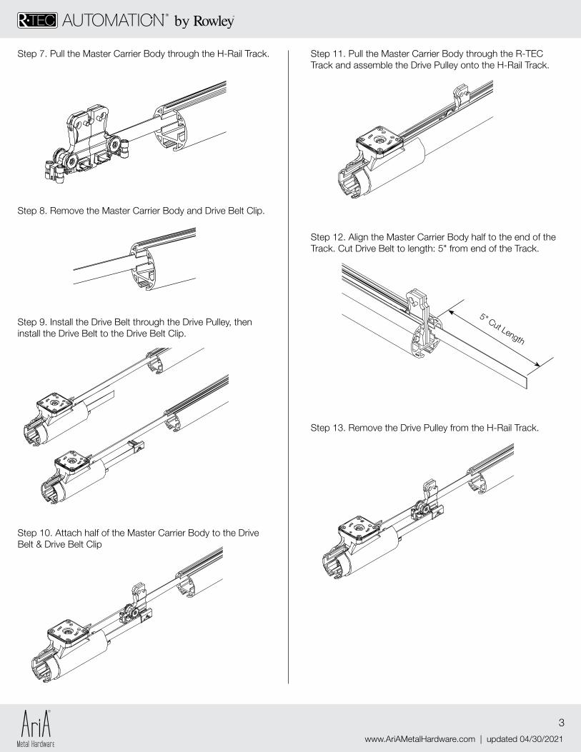
Step 11. Pull the Master Carrier Body through the R-TEC Track and assemble the Drive Pulley onto the H-Rail Track.
Step 13. Remove the Drive Pulley from the H-Rail Track.
www.AriAMetalHardware.com | updated 04/30/2021
3
Step 7. Pull the Master Carrier Body through the H-Rail Track.
Step 9. Install the Drive Belt through the Drive Pulley, then install the Drive Belt to the Drive Belt Clip.
Step 10. Attach half of the Master Carrier Body to the Drive Belt & Drive Belt Clip
Step 8. Remove the Master Carrier Body and Drive Belt Clip.
5" Cut Length
Step 12. Align the Master Carrier Body half to the end of the Track. Cut Drive Belt to length: 5" from end of the Track.
www.AriAMetalHardware.com | updated 04/30/2021
4
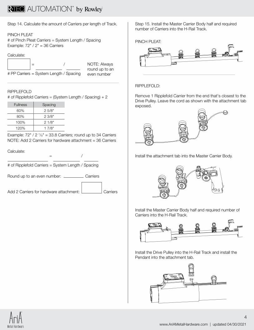
Step 15. Install the Master Carrier Body half and required number of Carriers into the H-Rail Track.
PINCH PLEAT:
RIPPLEFOLD:
Remove 1 Ripplefold Carrier from the end that's closest to the Drive Pulley. Leave the cord as shown with the attachment tab exposed.
Install the attachment tab into the Master Carrier Body.
Install the Master Carrier Body half and required number of Carriers into the H-Rail Track.
Install the Drive Pulley into the H-Rail Track and install the Pendant into the attachment tab.
RIPPLEFOLD # of Ripplefold Carriers = (System Length / Spacing) + 2
Example: 72" / 2 1/8" = 33.8 Carriers; round up to 34 CarriersNOTE: Add 2 Carriers for hardware attachment = 36 Carriers
Fullness Spacing
60% 2 5/8"
80% 2 3/8"
100% 2 1/8"
120% 1 7/8"
# of Ripplefold Carriers = System Length / Spacing
Round up to an even number:
Add 2 Carriers for hardware attachment:
Carriers
Carriers
Calculate: = /
Step 14. Calculate the amount of Carriers per length of Track.
PINCH PLEAT# of Pinch Pleat Carriers = System Length / SpacingExample: 72" / 2" = 36 Carriers
NOTE: Always round up to an even number# PP Carriers = System Length / Spacing
Calculate:
= /
www.AriAMetalHardware.com | updated 04/30/2021
5
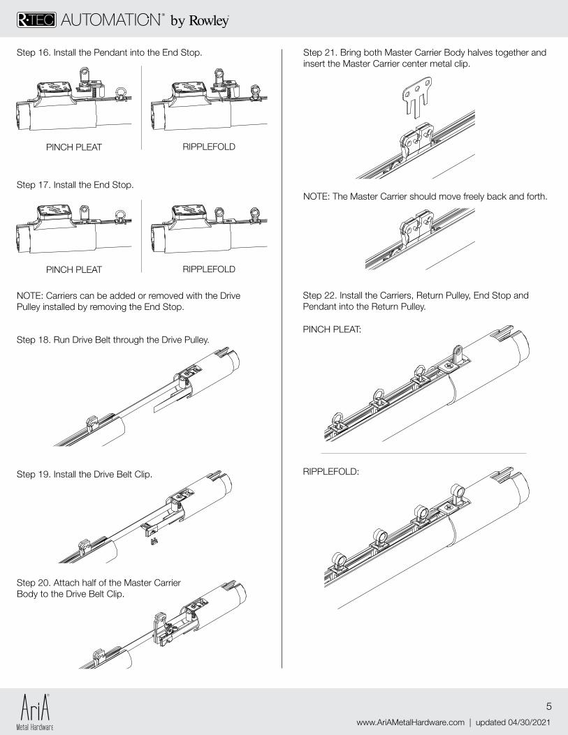
Step 17. Install the End Stop.
Step 16. Install the Pendant into the End Stop.
PINCH PLEAT RIPPLEFOLD
NOTE: Carriers can be added or removed with the Drive Pulley installed by removing the End Stop.
PINCH PLEAT RIPPLEFOLD
Step 21. Bring both Master Carrier Body halves together and insert the Master Carrier center metal clip.
NOTE: The Master Carrier should move freely back and forth.
Step 22. Install the Carriers, Return Pulley, End Stop and Pendant into the Return Pulley.
PINCH PLEAT:
RIPPLEFOLD:
Step 18. Run Drive Belt through the Drive Pulley.
Step 19. Install the Drive Belt Clip.
Step 20. Attach half of the Master Carrier Body to the Drive Belt Clip.
www.AriAMetalHardware.com | updated 04/30/2021
6DOWNLOAD INSTRUCTIONS:
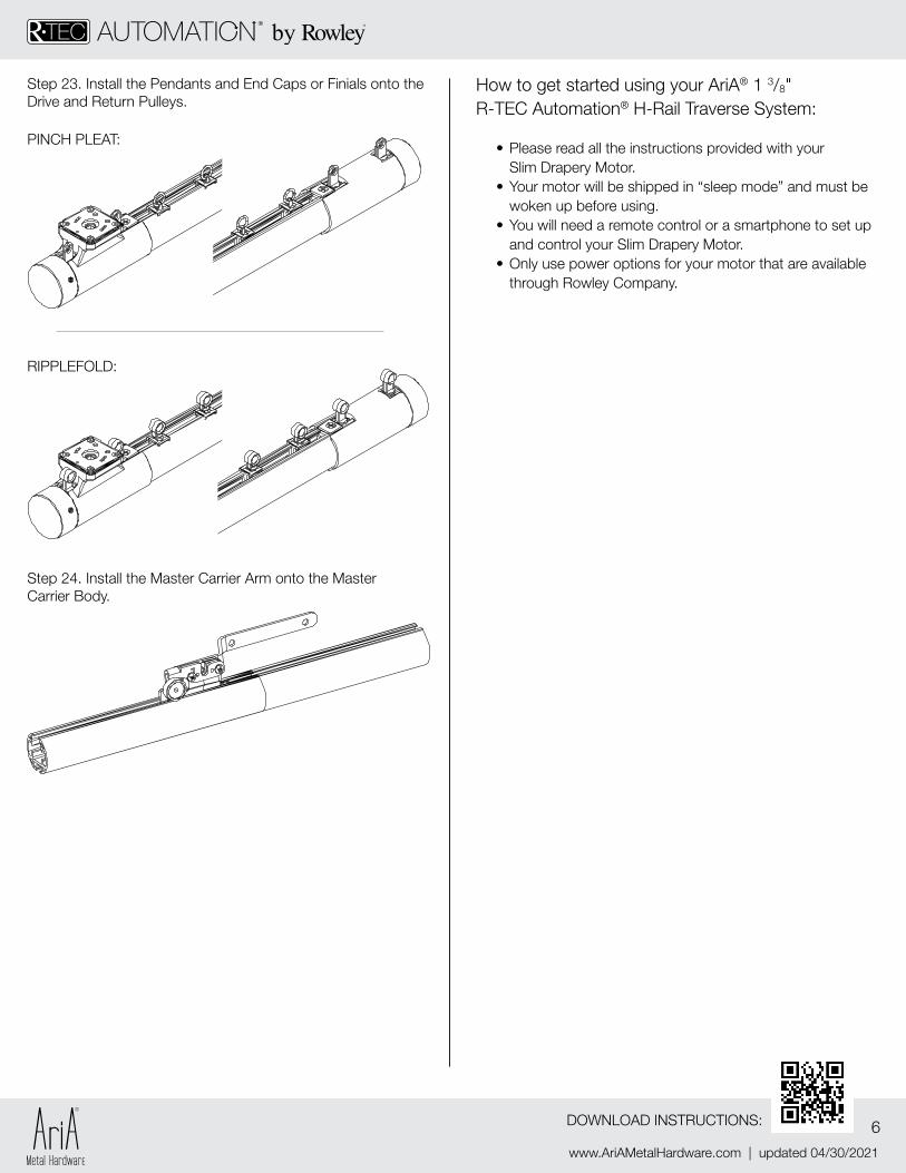
How to get started using your AriA® 1 3/8" R-TEC Automation® H-Rail Traverse System:
• Please read all the instructions provided with your Slim Drapery Motor.
• Your motor will be shipped in “sleep mode” and must be woken up before using.
• You will need a remote control or a smartphone to set up and control your Slim Drapery Motor.
• Only use power options for your motor that are available through Rowley Company.
Step 23. Install the Pendants and End Caps or Finials onto the Drive and Return Pulleys.
Step 24. Install the Master Carrier Arm onto the Master Carrier Body.
PINCH PLEAT:
RIPPLEFOLD: