Embed Size (px)
Citation preview
ASML, Brion and Computational Lithography
Neal Callan15 October 2008, Veldhoven
Slide 2 |
’02 ’03 ’04 ’05 ’06 ’07 ’08 ’09 ’10 ’11 ’12 ’13 ’14Year of production start*
Res
olut
ion,
"Shr
ink"
(nm
)
100
80
60
40
30
20
50
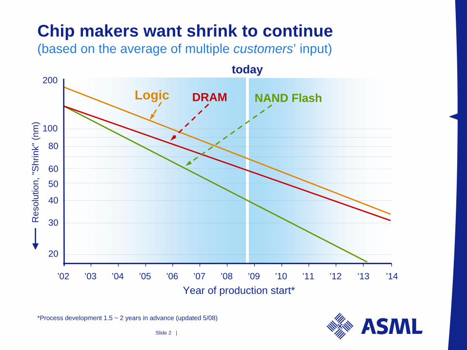
*Process development 1.5 ~ 2 years in advance (updated 5/08)
200
Chip makers want shrink to continue (based on the average of multiple customers’ input)
today
DRAMLogic NAND Flash
Slide 3 |
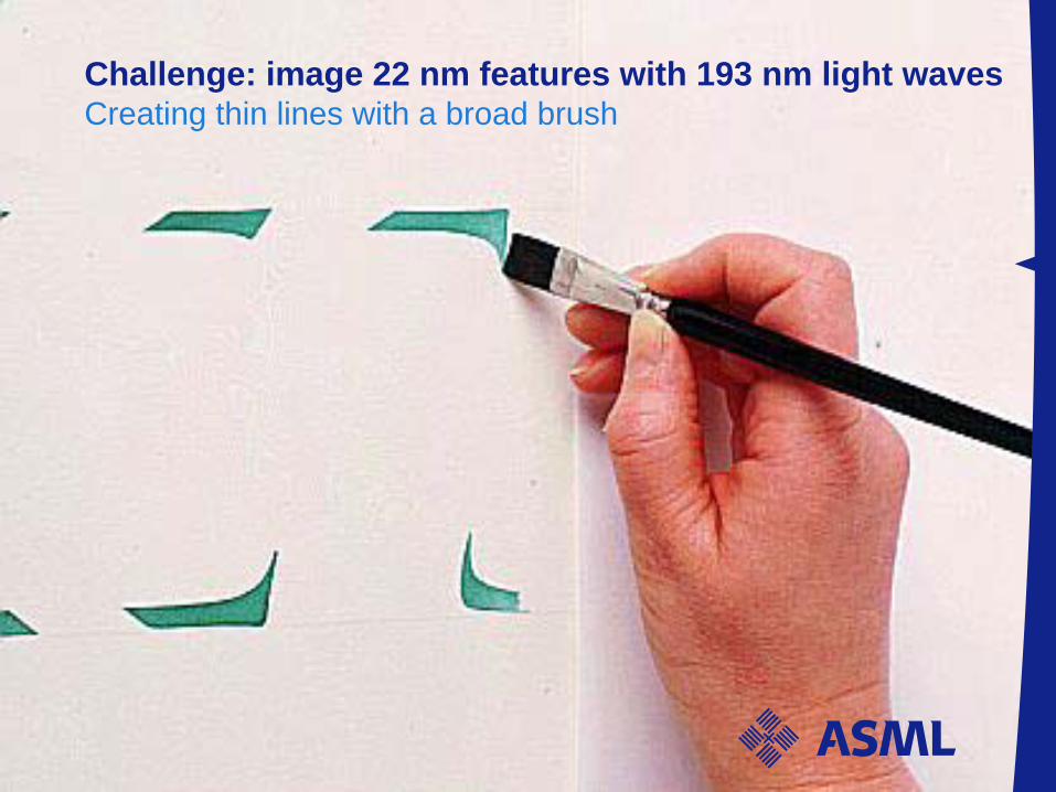
Challenge: image 22 nm features with 193 nm light waves Creating thin lines with a broad brush
Slide 4 |
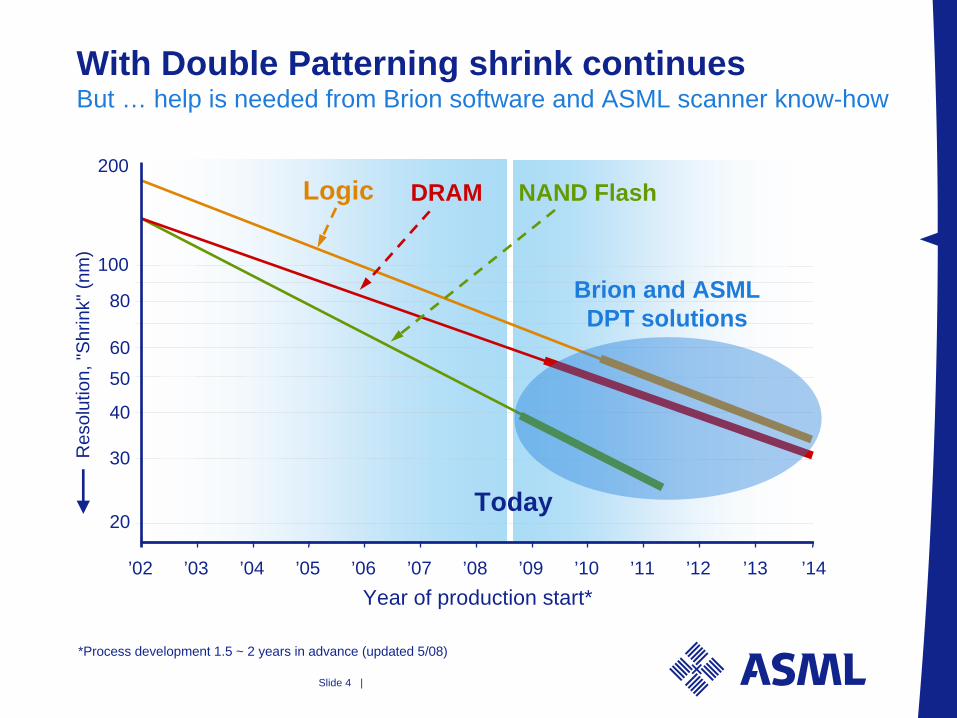
Today
’02 ’03 ’04 ’05 ’06 ’07 ’08 ’09 ’10 ’11 ’12 ’13 ’14Year of production start*
Res
olut
ion,
"Shr
ink"
(nm
)
100
80
60
40
30
20
50
*Process development 1.5 ~ 2 years in advance (updated 5/08)
200
With Double Patterning shrink continues But … help is needed from Brion software and ASML scanner know-how
Brion and ASML DPT solutions
DRAMLogic NAND Flash
Slide 5 |
Contents
1. Computational Lithography today
2. Brion and Holistic Lithographya. Combine mask and shape of light source =
Source-Mask Optimization (SMO)
b. Improved mask designs -- Open standards for mask design
c. The need to match scanners
Slide 6 |
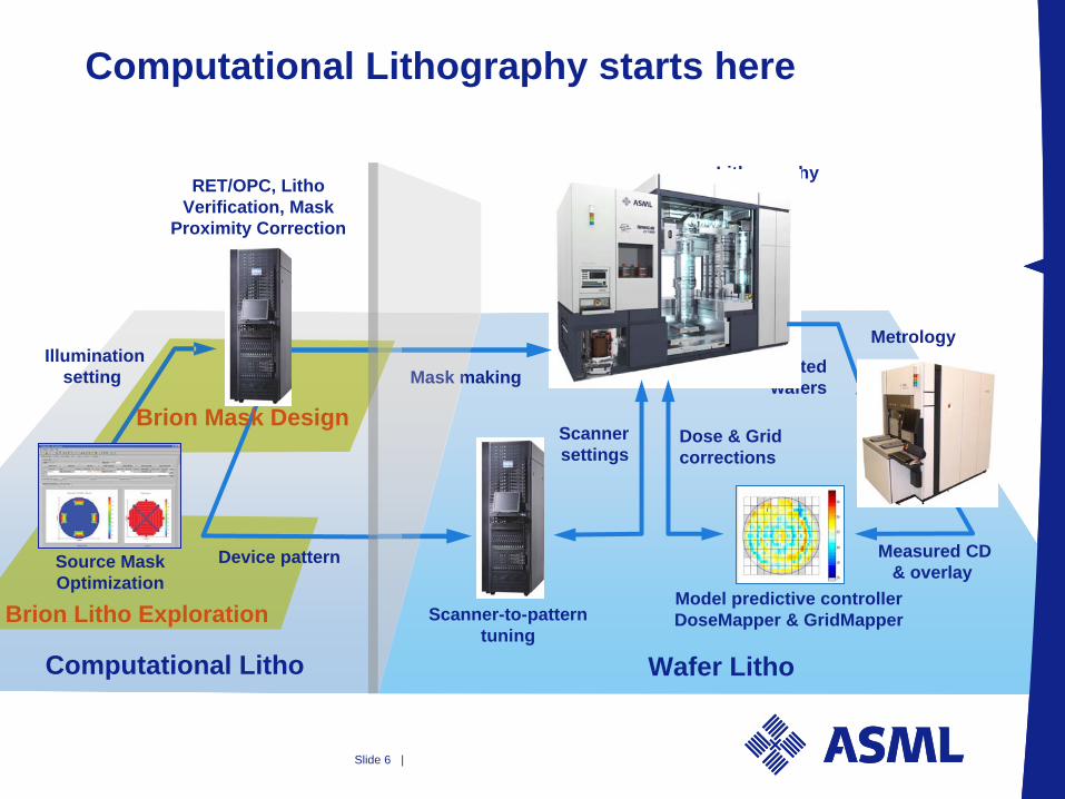
Computational Lithography starts here
LithographyRET/OPC, Litho
Verification, MaskProximity Correction
Scanner-to-patterntuning
Metrology
Model predictive controllerDoseMapper & GridMapper
Printed wafers
Measured CD& overlay
Computational Litho Wafer Litho
Mask making
Dose & Gridcorrections
Scannersettings
Source Mask Optimization
Brion Litho Exploration
Device pattern
Brion Mask Design
Illuminationsetting
Slide 7 |
Contents
1. Computational Lithography today
2. Brion and Holistic Lithographya. Combine mask and shape of light source =
Source-Mask Optimization (SMO)
b. Improved mask designs -- Open standards for mask design
c. The need to match scanners
Slide 8 |
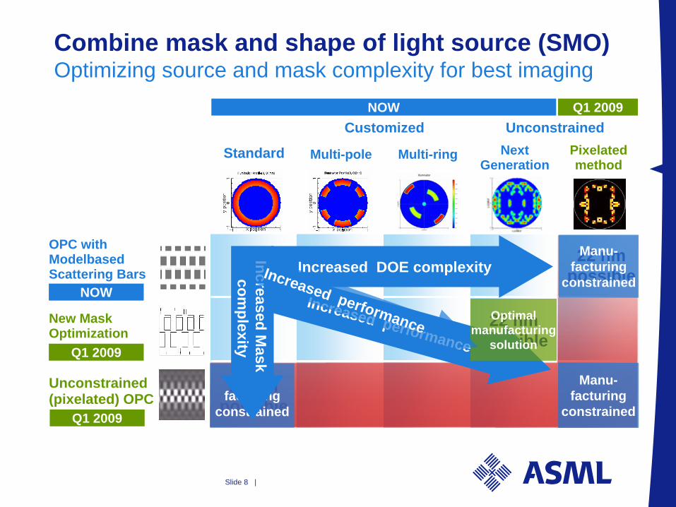
Combine mask and shape of light source (SMO) Optimizing source and mask complexity for best imaging
Standard
Customized Unconstrained
Multi-pole Multi-ring Next Generation
Pixelated method
OPC with Modelbased Scattering Bars
New MaskOptimization
Unconstrained(pixelated) OPC
22 nmpossible
22 nmpossible
22 nmpossible
Manu-facturing
constrained
Manu-facturing
constrained
Manu-facturing
constrained
Increased DOE complexity
Increased performance
Increased Mask
complexity
Optimalmanufacturing
solution
Increased performance
NOW
Q1 2009
Q1 2009
NOW Q1 2009
Slide 9 |
Contents
1. Computational Lithography today
2. Brion and Holistic Lithographya. Combine mask and shape of light source =
Source-Mask Optimization (SMO)
b. Improved mask designs -- Open standards for mask design
c. The need to match scanners
Slide 10 |
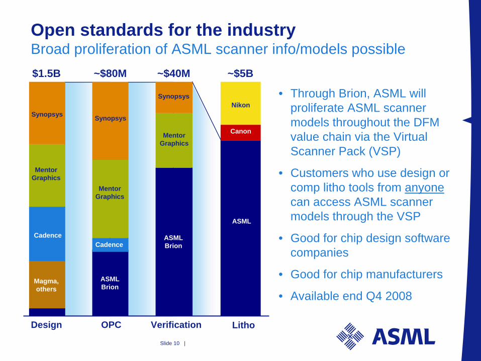
Open standards for the industry Broad proliferation of ASML scanner info/models possible
• Through Brion, ASML will proliferate ASML scanner models throughout the DFM value chain via the Virtual Scanner Pack (VSP)
• Customers who use design or comp litho tools from anyone can access ASML scanner models through the VSP
• Good for chip design software companies
• Good for chip manufacturers
• Available end Q4 2008
Litho
~$5B
ASML
Canon
Nikon
Verification
~$40M
Synopsys
MentorGraphics
ASMLBrion
Design
$1.5B
Synopsys
MentorGraphics
Cadence
Magma,others
OPC
~$80M
Synopsys
MentorGraphics
ASMLBrion
Cadence
Slide 11 |
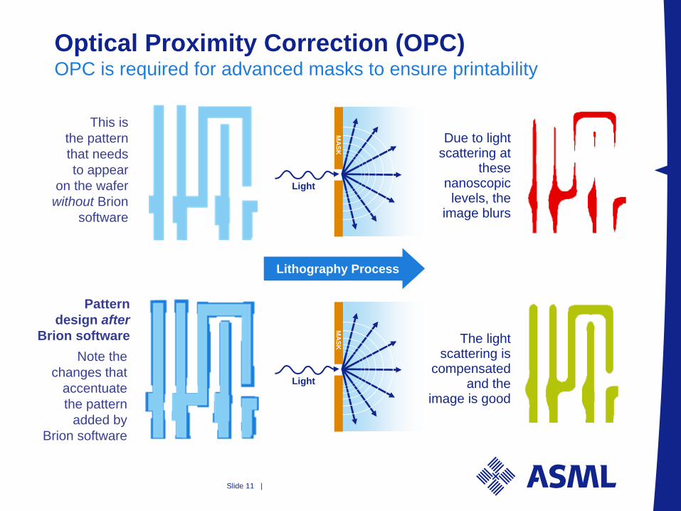
Optical Proximity Correction (OPC) OPC is required for advanced masks to ensure printability
This is the pattern that needs to appear
on the wafer without Brion
software
Pattern design after
Brion softwareNote the
changes that accentuate the pattern
added by Brion software
Due to light scattering at
these nanoscopic levels, the
image blurs
The light scattering is
compensated and the
image is goodLight
MASK
Lithography Process
Light
MASK
Slide 12 |
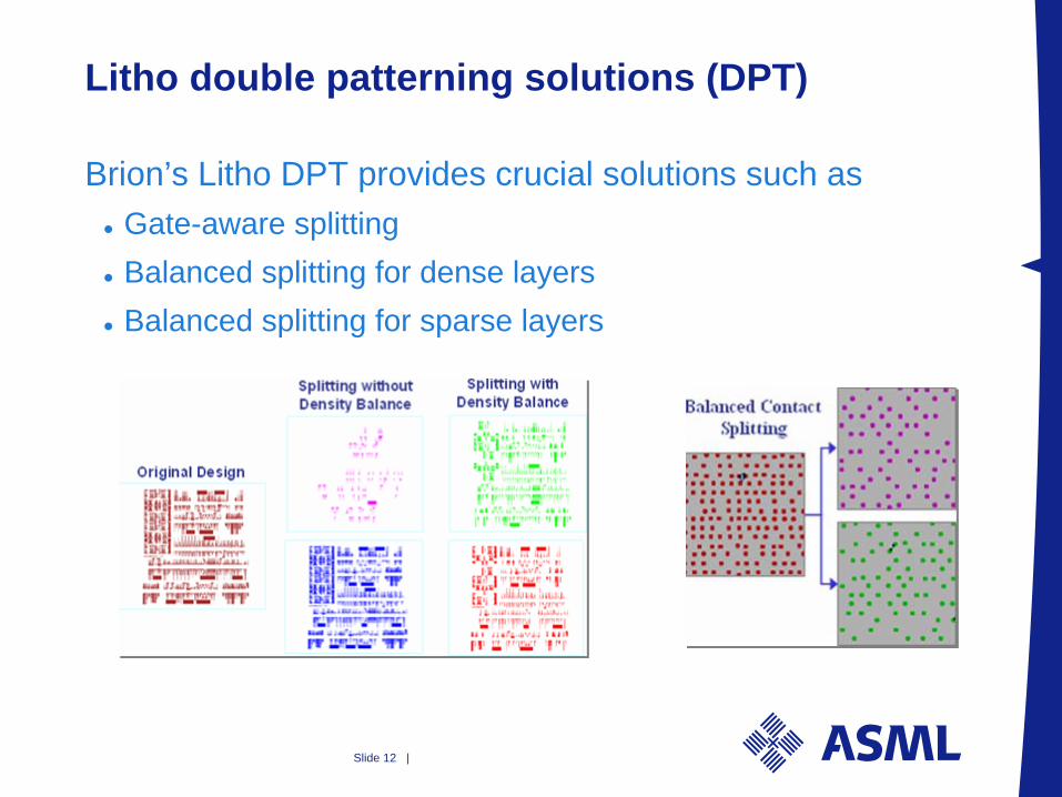
Litho double patterning solutions (DPT)
Brion’s Litho DPT provides crucial solutions such asGate-aware splittingBalanced splitting for dense layersBalanced splitting for sparse layers
Slide 13 |
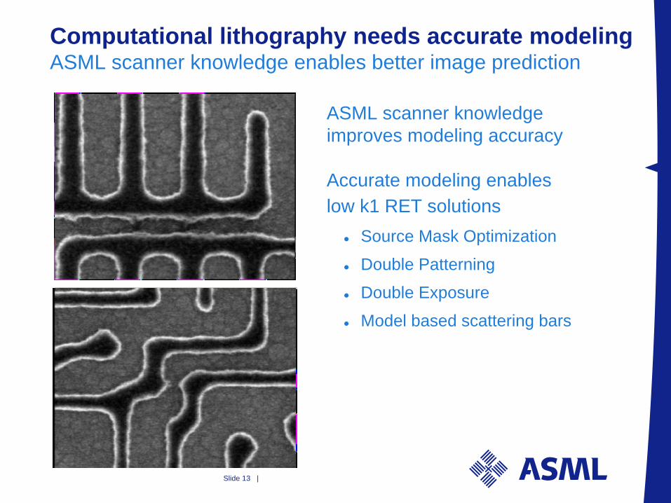
Computational lithography needs accurate modeling ASML scanner knowledge enables better image prediction
ASML scanner knowledge improves modeling accuracy
Accurate modeling enables low k1 RET solutions
Source Mask Optimization
Double Patterning
Double Exposure
Model based scattering bars
Slide 14 |
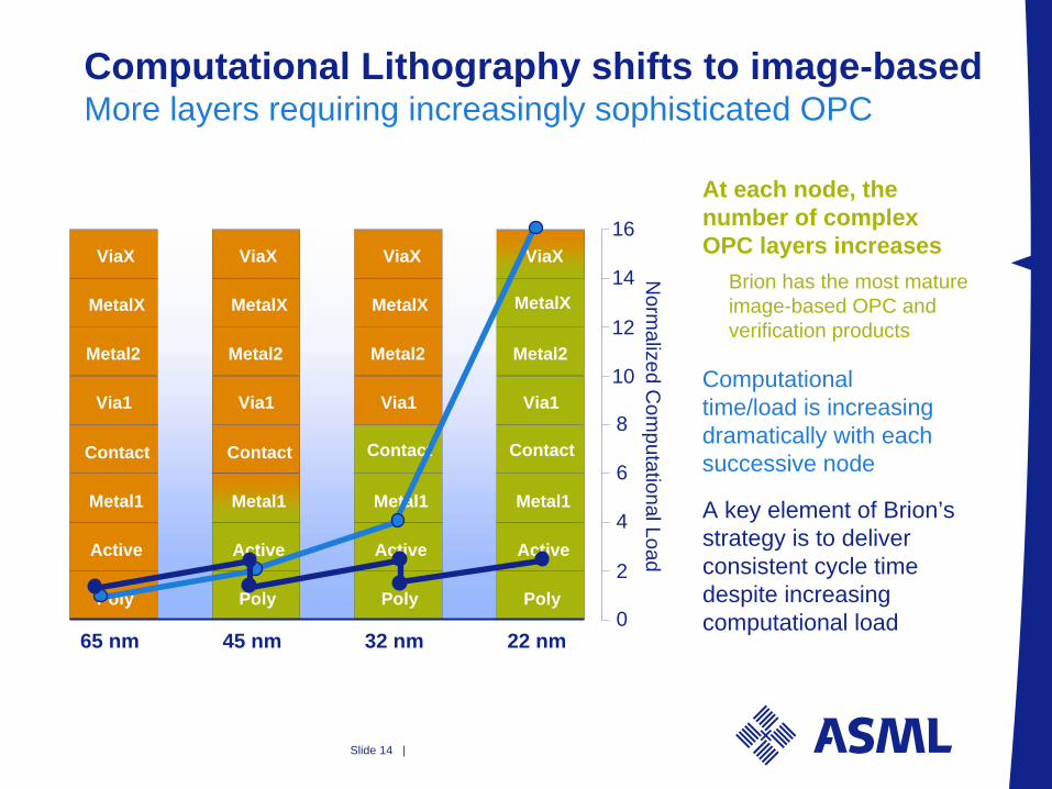
Computational Lithography shifts to image-based More layers requiring increasingly sophisticated OPC
45 nm 32 nm 22 nm65 nm
Poly
Active
Metal1
Contact
Via1
Metal2
MetalX
ViaX
Poly
Active
Metal1
Contact
Via1
Metal2
MetalX
ViaX
Poly
Active
Metal1
Contact
Via1
Metal2
MetalX
ViaX
Poly
Active
Metal1
Contact
Via1
Metal2
ViaX
0
2
4
6
8
10
12
14
16
Norm
alized Com
putational Load
MetalX
At each node, the number of complex OPC layers increases
Brion has the most mature image-based OPC and verification products
Computational time/load is increasing dramatically with each successive node
A key element of Brion’s strategy is to deliver consistent cycle time despite increasing computational load
Slide 15 |
Contents
1. Computational Lithography today
2. Brion and Holistic Lithographya. Combine mask and shape of light source =
Source-Mask Optimization (SMO)
b. Improved mask designs -- Open standards for mask design
c. The need to match scanners
Slide 16 |
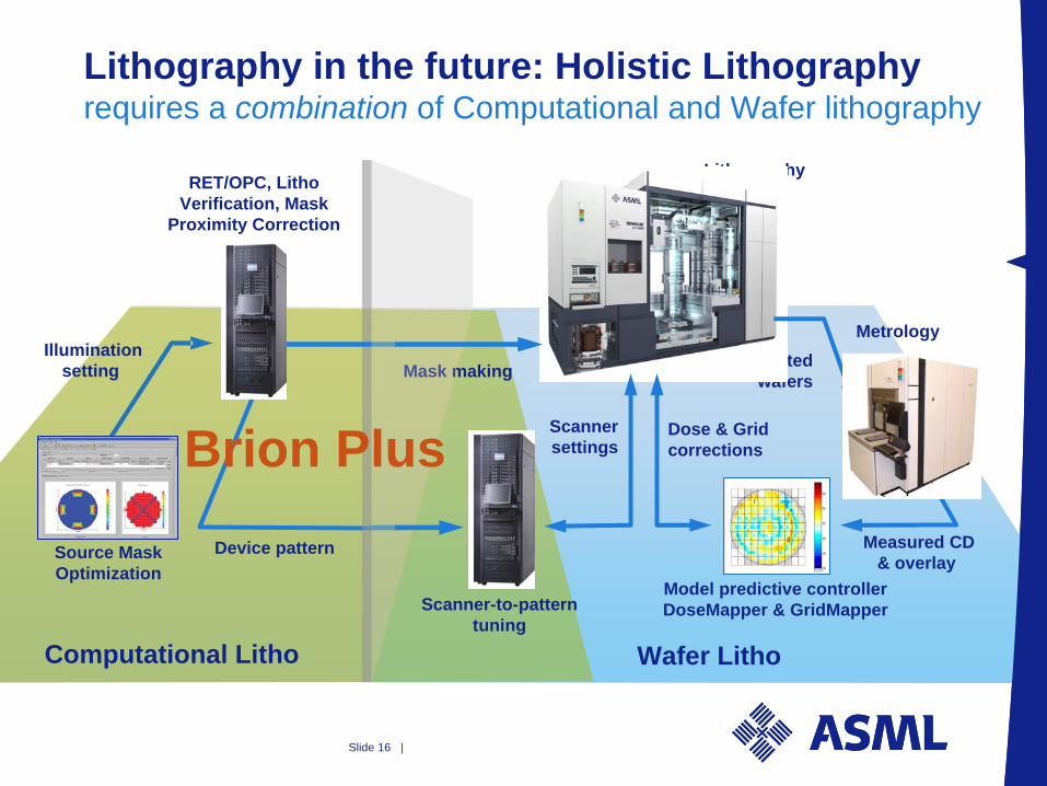
Lithography in the future: Holistic Lithography requires a combination of Computational and Wafer lithography
Lithography
Source Mask Optimization
RET/OPC, LithoVerification, Mask
Proximity Correction
Scanner-to-patterntuning
Metrology
Model predictive controllerDoseMapper & GridMapper
Illuminationsetting
Device pattern
Printed wafers
Measured CD& overlay
Computational Litho Wafer Litho
Mask making
Dose & Gridcorrections
ScannersettingsBrion Plus
Slide 17 |
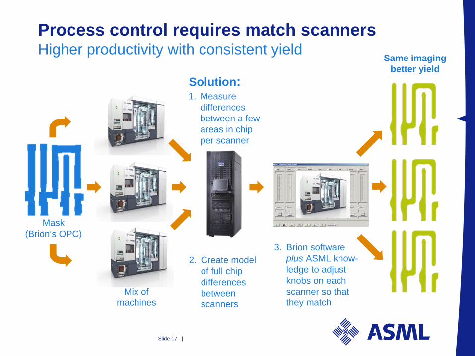
Process control requires match scanners Higher productivity with consistent yield
Mix of machines
2. Create model of full chip differences between scanners
Solution:1. Measure
differences between a few areas in chip per scanner
Same imaging better yield
Mask (Brion’s OPC)
3. Brion software plus ASML know- ledge to adjust knobs on each scanner so that they match

Slide 18 |
Added complexity to match scanners Simple core structures no longer enough
Yesterday --Simple, core patterns were matched
NAND wordline
Periphery
Today --All critical patterns need to be simultaneously matched
High performance SRAM
Slide 19 |
In Summary
• Brion + ASML optimizes the design to the scannersSource-Mask OptimizationDouble PatterningVirtual Scanner Pack
• Brion + ASML optimizes the scanners to the designsHolistic Lithography -- matching