Embed Size (px)
Citation preview
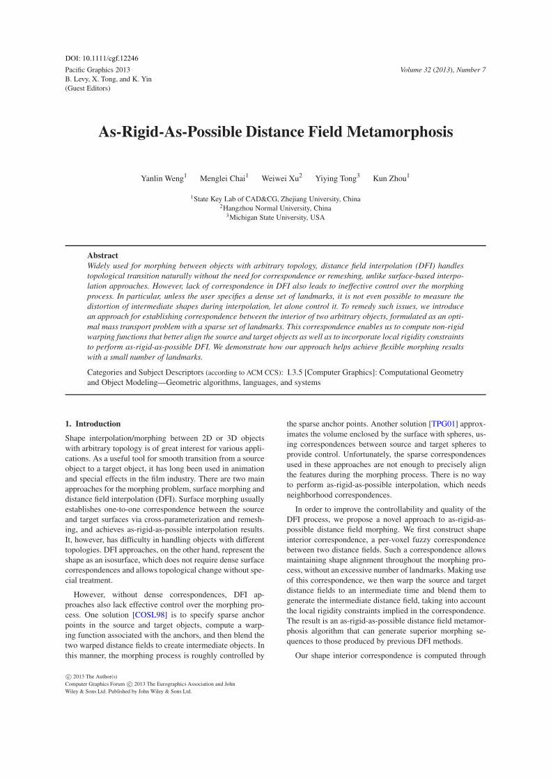
Pacific Graphics 2013B. Levy, X. Tong, and K. Yin(Guest Editors)
Volume 32 (2013), Number 7
As-Rigid-As-Possible Distance Field Metamorphosis
Yanlin Weng1 Menglei Chai1 Weiwei Xu2 Yiying Tong3 Kun Zhou1
1State Key Lab of CAD&CG, Zhejiang University, China2Hangzhou Normal University, China
3Michigan State University, USA
Abstract
Widely used for morphing between objects with arbitrary topology, distance field interpolation (DFI) handles
topological transition naturally without the need for correspondence or remeshing, unlike surface-based interpo-
lation approaches. However, lack of correspondence in DFI also leads to ineffective control over the morphing
process. In particular, unless the user specifies a dense set of landmarks, it is not even possible to measure the
distortion of intermediate shapes during interpolation, let alone control it. To remedy such issues, we introduce
an approach for establishing correspondence between the interior of two arbitrary objects, formulated as an opti-
mal mass transport problem with a sparse set of landmarks. This correspondence enables us to compute non-rigid
warping functions that better align the source and target objects as well as to incorporate local rigidity constraints
to perform as-rigid-as-possible DFI. We demonstrate how our approach helps achieve flexible morphing results
with a small number of landmarks.
Categories and Subject Descriptors (according to ACM CCS): I.3.5 [Computer Graphics]: Computational Geometryand Object Modeling—Geometric algorithms, languages, and systems
1. Introduction
Shape interpolation/morphing between 2D or 3D objectswith arbitrary topology is of great interest for various appli-cations. As a useful tool for smooth transition from a sourceobject to a target object, it has long been used in animationand special effects in the film industry. There are two mainapproaches for the morphing problem, surface morphing anddistance field interpolation (DFI). Surface morphing usuallyestablishes one-to-one correspondence between the sourceand target surfaces via cross-parameterization and remesh-ing, and achieves as-rigid-as-possible interpolation results.It, however, has difficulty in handling objects with differenttopologies. DFI approaches, on the other hand, represent theshape as an isosurface, which does not require dense surfacecorrespondences and allows topological change without spe-cial treatment.
However, without dense correspondences, DFI ap-proaches also lack effective control over the morphing pro-cess. One solution [COSL98] is to specify sparse anchorpoints in the source and target objects, compute a warp-ing function associated with the anchors, and then blend thetwo warped distance fields to create intermediate objects. Inthis manner, the morphing process is roughly controlled by
the sparse anchor points. Another solution [TPG01] approx-imates the volume enclosed by the surface with spheres, us-ing correspondences between source and target spheres toprovide control. Unfortunately, the sparse correspondencesused in these approaches are not enough to precisely alignthe features during the morphing process. There is no wayto perform as-rigid-as-possible interpolation, which needsneighborhood correspondences.
In order to improve the controllability and quality of theDFI process, we propose a novel approach to as-rigid-as-possible distance field morphing. We first construct shapeinterior correspondence, a per-voxel fuzzy correspondencebetween two distance fields. Such a correspondence allowsmaintaining shape alignment throughout the morphing pro-cess, without an excessive number of landmarks. Making useof this correspondence, we then warp the source and targetdistance fields to an intermediate time and blend them togenerate the intermediate distance field, taking into accountthe local rigidity constraints implied in the correspondence.The result is an as-rigid-as-possible distance field metamor-phosis algorithm that can generate superior morphing se-quences to those produced by previous DFI methods.
Our shape interior correspondence is computed through
c© 2013 The Author(s)
Computer Graphics Forum c© 2013 The Eurographics Association and John
Wiley & Sons Ltd. Published by John Wiley & Sons Ltd.
DOI: 10.1111/cgf.12246
Y. Weng et al. / As-Rigid-As-Possible Distance Field Metamorphosis
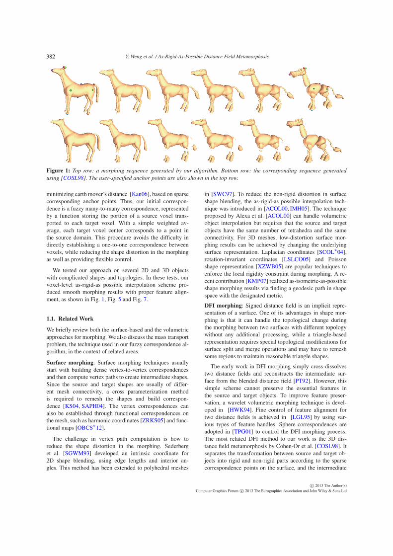
Figure 1: Top row: a morphing sequence generated by our algorithm. Bottom row: the corresponding sequence generated
using [COSL98]. The user-specified anchor points are also shown in the top row.
minimizing earth mover’s distance [Kan06], based on sparsecorresponding anchor points. Thus, our initial correspon-dence is a fuzzy many-to-many correspondence, representedby a function storing the portion of a source voxel trans-ported to each target voxel. With a simple weighted av-erage, each target voxel center corresponds to a point inthe source domain. This procedure avoids the difficulty indirectly establishing a one-to-one correspondence betweenvoxels, while reducing the shape distortion in the morphingas well as providing flexible control.
We tested our approach on several 2D and 3D objectswith complicated shapes and topologies. In these tests, ourvoxel-level as-rigid-as possible interpolation scheme pro-duced smooth morphing results with proper feature align-ment, as shown in Fig. 1, Fig. 5 and Fig. 7.
1.1. Related Work
We briefly review both the surface-based and the volumetricapproaches for morphing. We also discuss the mass transportproblem, the technique used in our fuzzy correspondence al-gorithm, in the context of related areas.
Surface morphing: Surface morphing techniques usuallystart with building dense vertex-to-vertex correspondencesand then compute vertex paths to create intermediate shapes.Since the source and target shapes are usually of differ-ent mesh connectivity, a cross parameterization methodis required to remesh the shapes and build correspon-dence [KS04, SAPH04]. The vertex correspondences canalso be established through functional correspondences onthe mesh, such as harmonic coordinates [ZRKS05] and func-tional maps [OBCS∗12].
The challenge in vertex path computation is how toreduce the shape distortion in the morphing. Sederberget al. [SGWM93] developed an intrinsic coordinate for2D shape blending, using edge lengths and interior an-gles. This method has been extended to polyhedral meshes
in [SWC97]. To reduce the non-rigid distortion in surfaceshape blending, the as-rigid-as possible interpolation tech-nique was introduced in [ACOL00, IMH05]. The techniqueproposed by Alexa et al. [ACOL00] can handle volumetricobject interpolation but requires that the source and targetobjects have the same number of tetrahedra and the sameconnectivity. For 3D meshes, low-distortion surface mor-phing results can be achieved by changing the underlyingsurface representation. Laplacian coordinates [SCOL∗04],rotation-invariant coordinates [LSLCO05] and Poissonshape representation [XZWB05] are popular techniques toenforce the local rigidity constraint during morphing. A re-cent contribution [KMP07] realized as-isometric-as-possibleshape morphing results via finding a geodesic path in shapespace with the designated metric.
DFI morphing: Signed distance field is an implicit repre-sentation of a surface. One of its advantages in shape mor-phing is that it can handle the topological change duringthe morphing between two surfaces with different topologywithout any additional processing, while a triangle-basedrepresentation requires special topological modifications forsurface split and merge operations and may have to remeshsome regions to maintain reasonable triangle shapes.
The early work in DFI morphing simply cross-dissolvestwo distance fields and reconstructs the intermediate sur-face from the blended distance field [PT92]. However, thissimple scheme cannot preserve the essential features inthe source and target objects. To improve feature preser-vation, a wavelet volumetric morphing technique is devel-oped in [HWK94]. Fine control of feature alignment fortwo distance fields is achieved in [LGL95] by using var-ious types of feature handles. Sphere correspondences areadopted in [TPG01] to control the DFI morphing process.The most related DFI method to our work is the 3D dis-tance field metamorphosis by Cohen-Or et al. [COSL98]. Itseparates the transformation between source and target ob-jects into rigid and non-rigid parts according to the sparsecorrespondence points on the surface, and the intermediate
c© 2013 The Author(s)
Computer Graphics Forum c© 2013 The Eurographics Association and John Wiley & Sons Ltd
382
Y. Weng et al. / As-Rigid-As-Possible Distance Field Metamorphosis
distance field is generated by blending the warped distancefields.
As described earlier, the advantage of our algorithm is tocompute a dense shape interior correspondence, which al-lows the shape alignment to be consistent with the 3D ob-jects enclosed by the surfaces. To our knowledge, ours isthe first algorithm that incorporates local rigidity constraintsinto DFI morhping, leading to reduced distortion.
Mass transport: We model the morphing problem as amass transport problem, a shape transformation with a masspreservation property, where the weighted 2D or 3D volumeis treated as the mass to be transported. The optimal masstransport of this sort was first considered in 1781 by GaspardMonge, who referred to it as the “Earth Mover’s Distance”(EMD). Its modern formulation first appeared in [Kan06].Optimal mass transport has been applied to image regis-tration [HZTA04], content-based image retrieval [RTG00]and feature similarity measure [GD05]. In [MY11], EMDis also applied to topology free 2D image morphing. How-ever, explicit non-rigid distortion control is not directlyavailable in this method, which hinders its application toshape morphing with the feature preservation requirement.In [LPD11, SNB∗12], EMD is used to compute soft corre-spondences between surfaces.
1.2. Overview
We present the overall framework here, before elaboratingon the algorithm in the following sections.
The two given 3D solid objects, a source Ω0 and a tar-get Ω1, are represented as signed distance fields to their re-spective boundary surfaces, D0 and D1, stored on a volumet-ric grid. More precisely, for any point q in the domain, thevalue of D0(q) (or D1(q)) is defined as the signed shortestEuclidean distance between q and the boundary of Ω0 (orΩ1), negative for points inside the objects and positive forthe outside points. Our goal is to continuously deform Ω0 toΩ1 and produce the in-between objects Ωt ,0 < t < 1 (i.e.,Dt ,0 < t < 1). The user can specify a set of anchor pointpairs (pi
0, pi1),1 ≤ i ≤ K, such that point pi
0 in the sourcedomain corresponds to point pi
1 in the target domain.
Our algorithm first establishes a fuzzy correspondence be-tween the interiors of Ω0 and Ω1 (Sec. 2). Treating morphingas a process of transporting the mass of Ω0 to Ω1, we formu-late the correspondence as the solution to an optimal masstransport problem from the interior voxels of Ω0 to those ofΩ1. The underlying physical optimality of this correspon-dence makes the morphing results reasonable, in the sensethat it moves the voxels with the minimum total transportcost. To produce correspondences consistent with the user-specified anchor pairs, we define a mass transportation costinduced by the anchor points.
Making use of the above correspondence, we use thin
plate spline interpolation to compute warping functionsW0→1 and W1→0 that can align the shapes of Ω0 and Ω1
as well as possible (Sec. 3.1), i.e.,
W0→1(Ω0)≈ Ω1, W1→0(Ω1)≈ Ω0. (1)
Next, given a morphing parameter t ∈ [0,1], we find warp-ing functions W0→t (W1→t ) that can transform Ω0 (Ω1) totime t (Sec. 3.2) as an as-rigid-as-possible interpolation be-tween the identity transformation and W0→1 (W1→0). Wethen compute their inverses, the backward mapping func-tions Bt→0 and Bt→1. Finally, the distance field Dt at t canbe evaluated as the interpolation of D0 and D1 guided by thebackward mappings:
Dt(v) = (1− t)D0(Bt→0(v))+ tD1(Bt→1(v)), (2)
where v is an arbitrary voxel in the domain.
Once we have the distance field, we can use the marchingcubes method [LC87] to extract the zero set surface, whichis represented as a triangular mesh. Note that the extractedmeshes at contiguous time frames may have different num-ber of vertices/triangles and connectivity, and it is difficultto enforce any temporal coherence between the two meshes.Fortunately, in practice, we found that the generated morph-ing sequences exhibit smooth transition as demonstrated inour video demo. It is also possible to use the recent surfacetracking technique [BHLW12] to track the correspondencefor the mesh sequence and improve the mesh coherence.
2. Shape Interior Correspondence
We formulate the desired shape interior correspondence be-tween Ω0 and Ω1 as the optimal mass transport. Supposethat the total mass of a solid object is a constant value 1,evenly distributed among its interior voxels. The problem isthen to find a mapping f that transports all the mass fromthe interior voxels of Ω0 to those of Ω1 with the minimaltransportation cost.
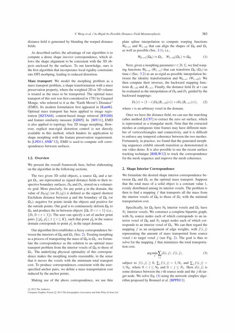
Specifically, let Ω0 have N0 interior voxels and Ω1 haveN1 interior voxels. We construct a complete bipartite graph,with N0 source nodes each of which corresponds to an in-terior voxel of Ω0 and N1 target nodes each of which cor-responds to an interior voxel of Ω1. We can then regard themapping f as an assignment of edge weights, with f (i, j)representing the amount of mass transported from sourcevoxel i to target voxel j (see Fig. 2). The goal is thus tosolve for the mapping f that minimizes the total transporta-tion cost,
argminf
∑i, j
d(i, j) · f (i, j), (3)
subject to f (i, j) ≥ 0, ∑i f (i, j) = 1/N1 and ∑ j f (i, j) =1/N0, where 0 < i ≤ N0 and 0 < j ≤ N1. Here d(i, j) issome distance between the i-th source node and the j-th tar-get node. We solve Eq. (3) using the network simplex algo-rithm proposed by Bonneel et al. [BPPH11].
c© 2013 The Author(s)
Computer Graphics Forum c© 2013 The Eurographics Association and John Wiley & Sons Ltd
383
Y. Weng et al. / As-Rigid-As-Possible Distance Field Metamorphosis
f (i, j)
i j
Figure 2: Illustration of shape interior correspondence. For
every source node i and target node j, f (i, j) represents the
amount of mass transported from source voxel i to target
voxel j.
The distance d(i, j) between source nodes and targetnodes should be defined with the correspondence of user-specified anchor point pairs taken into account. Intuitively,if (i, j) is an anchor point pair, d(i, j) should be a mini-mal value to favor the mass transportation between the twonodes. Inspired by Zayer et al.’s work [ZRKS05], we com-pute a K-dimensional vector field in either of the sourceor target domains with respect to the K anchor point pairs.Specifically, for each source anchor point i, we compute aharmonic field hi
0 in the source domain with Dirichlet bound-ary conditions by setting its value to 1 at this anchor pointand to 0 at all other source anchor points. This is equivalentto solving the following linear system in the volumetric grid
∆hi0 = 0, with h
i0(p
i0) = 1, h
i0(p
j0) = 0, j 6= i, (4)
where ∆ = ∂2
∂x2 +∂2
∂y2 +∂2
∂z2 is the Laplacian operator. In our
current implementation, the Laplacian at voxel v, ∆hi0(v),
is calculated as hi0(v)−
16 ∑u∈Ψ(v) hi
0(u), where Ψ(v) rep-resents v’s 6-connected neighboring voxels.
Solving the above equation for all K source anchor pointsgives us a K-dimensional vector field h0 = (h1
0, ...,hK0 ). Sim-
ilarly we can compute a K-dimensional vector field h1 =(h1
1, ...,hK1 ) in the target domain. We then define the distance
between source node i and target node j as
d(i, j) = ‖h0(vi0)−h1(v
j1)‖, (5)
where vi0 and v
j1 are the positions of the i-th source node and
the j-th target node respectively.
Note that unlike [ZRKS05], we cannot directly use theharmonic fields to construct the correspondence as this maymake exterior regions of the source correspond to interior re-gions of the target or vice versa. We only use harmonic fieldsto calculate the distance between source and target nodes.The final correspondence is computed by minimizing the to-tal mass transportation cost.
The minimizer f of the total transportation cost gives amany-to-many correspondence: for each target node j, anysource node i that has a nonzero f (i, j) could partially cor-respond to j. To perform DFI, we need to compute a uniquecorresponding position in the source domain for each targetnode j. For this purpose, we first find the source node withthe largest f (i, j) with given j, i.e., l = argmaxi f (i, j). The
source corresponding position of the j-th target node, qj0, is
then computed through
qj0 =
∑k∈ϒ(l) f (k, j)vk0
∑k∈ϒ(l) f (k, j), (6)
where ϒ(l) is the 3× 3× 3 volume grid centered at sourcenode l. We can compute the target corresponding position qi
1of every source node i in a similar way.
Although we compute a unique corresponding position inthe source for each target node, such a correspondence isnot a one-to-one mapping between the source and target do-mains. Our intuition is that although the corresponding posi-tion of each individual node may not be optimal, the corre-sponding positions of all nodes can be used as a good guid-ance to aligning the source and target shapes. Note that aswe only need a fuzzy correspondence, we can also compute
qj0 as the the average position of all source nodes having
nonzero f (i, j) values. According to our experiments, thishardly affects the final morphing results.
3. As-Rigid-As-Possible Distance Field Interpolation
We first describe how to compute warping functions thatalign the source and target shapes as well as possible, thenintroduce an algorithm to perform as-rigid-as-possible inter-polation for these warping functions and generate the inter-mediate shape.
3.1. Computing Warping Functions
We employ thin plate spline (TPS) interpolation [Boo89] tocompute the warping functions from the dense correspon-dence computed in the previous section.
Specifically, to compute the warping function W1→0 fromthe target shape to the source shape, we solve the followingproblem
W1→0 = argminW
∑j
‖W (vj1)− q
j0‖
2 +λ
∫|D2
W |2, (7)
where D2W is the matrix of second-order partial derivativesof W and the matrix norm used in |D2W |2 is the Frobeniusnorm. The first term preserves the interior correspondence,and the second term ensures the smoothness of the warping.The weight λ is set to 0.5 in all of our tests.
The above problem has a closed form solution when re-stricted to the following form:
W1→0(p) = a1 +a2 px +a3 py +a4 pz +∑j
ciϕ(‖p− vj1‖),
(8)where px, py and pz indicate coordinate components of p,ϕ(r) = r2 logr is the kernel function, and a1, a2, a3, a4
and c j are mapping coefficients (∈ R3) solved from Eq. (7),
c© 2013 The Author(s)
Computer Graphics Forum c© 2013 The Eurographics Association and John Wiley & Sons Ltd
384
Y. Weng et al. / As-Rigid-As-Possible Distance Field Metamorphosis
i
j
k
l
i
k
l
j
i
j
k
l
(a) (b)
ik
l
j
(c) (d)
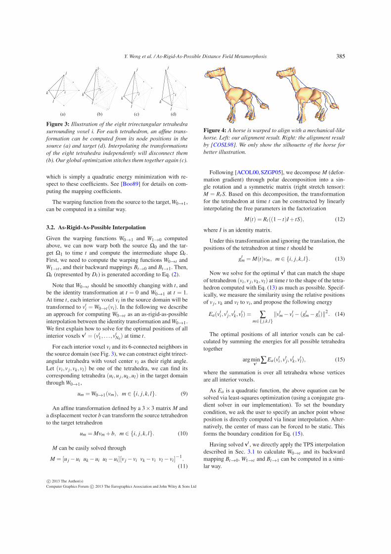
Figure 3: Illustration of the eight trirectangular tetrahedra
surrounding voxel i. For each tetrahedron, an affine trans-
formation can be computed from its node positions in the
source (a) and target (d). Interpolating the transformations
of the eight tetrahedra independently will disconnect them
(b). Our global optimization stitches them together again (c).
which is simply a quadratic energy minimization with re-spect to these coefficients. See [Boo89] for details on com-puting the mapping coefficients.
The warping function from the source to the target, W0→1,can be computed in a similar way.
3.2. As-Rigid-As-Possible Interpolation
Given the warping functions W0→1 and W1→0 computedabove, we can now warp both the source Ω0 and the tar-get Ω1 to time t and compute the intermediate shape Ωt .First, we need to compute the warping functions W0→t andW1→t , and their backward mappings Bt→0 and Bt→1. Then,Ωt (represented by Dt ) is generated according to Eq. (2).
Note that W0→t should be smoothly changing with t, andbe the identity transformation at t = 0 and W0→1 at t = 1.At time t, each interior voxel vi in the source domain will betransformed to vt
i =W0→t (vi). In the following we describean approach for computing W0→t as an as-rigid-as-possibleinterpolation between the identity transformation and W0→1.We first explain how to solve for the optimal positions of allinterior voxels vt = (vt
1, . . .,vtN0) at time t.
For each interior voxel vi and its 6-connected neighbors inthe source domain (see Fig. 3), we can construct eight trirect-angular tetrahedra with voxel center vi as their right angle.Let (vi,v j,vk,vl) be one of the tetrahedra, we can find itscorresponding tetrahedra (ui,u j,uk,ul) in the target domainthrough W0→1,
um =W0→1(vm), m ∈ i, j,k, l. (9)
An affine transformation defined by a 3×3 matrix M anda displacement vector b can transform the source tetrahedronto the target tetrahedron
um = Mvm +b, m ∈ i, j,k, l. (10)
M can be easily solved through
M = [u j − ui uk − ui ul − ui][v j − vi vk − vi vl − vi]−1.(11)
Figure 4: A horse is warped to align with a mechanical-like
horse. Left: our alignment result. Right: the alignment result
by [COSL98]. We only show the silhouette of the horse for
better illustration.
Following [ACOL00,SZGP05], we decompose M (defor-mation gradient) through polar decomposition into a sin-gle rotation and a symmetric matrix (right stretch tensor):M = RrS. Based on this decomposition, the transformationfor the tetrahedron at time t can be constructed by linearlyinterpolating the free parameters in the factorization
M(t) = Rt((1− t)I+ tS), (12)
where I is an identity matrix.
Under this transformation and ignoring the translation, thepositions of the tetrahedron at time t should be
gtm = M(t)vm, m ∈ i, j,k, l. (13)
Now we solve for the optimal vt that can match the shapeof tetrahedron (vi,v j,vk,vl) at time t to the shape of the tetra-hedron computed with Eq. (13) as much as possible. Specif-ically, we measure the similarity using the relative positionsof v j , vk and vl to vi, and propose the following energy
Ea(vti ,v
tj,v
tk,v
tl) = ∑
m∈ j,k,l
‖vtm − v
ti − (gt
m − gti)‖
2. (14)
The optimal positions of all interior voxels can be cal-culated by summing the energies for all possible tetrahedratogether
argminvt
∑Ea(vti ,v
tj,v
tk,v
tl), (15)
where the summation is over all tetrahedra whose verticesare all interior voxels.
As Ea is a quadratic function, the above equation can besolved via least-squares optimization (using a conjugate gra-dient solver in our implementation). To set the boundarycondition, we ask the user to specify an anchor point whoseposition is directly computed via linear interpolation. Alter-natively, the center of mass can be forced to be static. Thisforms the boundary condition for Eq. (15).
Having solved vt , we directly apply the TPS interpolationdescribed in Sec. 3.1 to calculate W0→t and its backwardmapping Bt→0. W1→t and Bt→1 can be computed in a simi-lar way.
c© 2013 The Author(s)
Computer Graphics Forum c© 2013 The Eurographics Association and John Wiley & Sons Ltd
385
Y. Weng et al. / As-Rigid-As-Possible Distance Field Metamorphosis
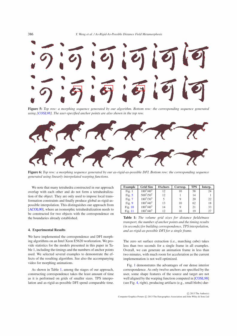
Figure 5: Top row: a morphing sequence generated by our algorithm. Bottom row: the corresponding sequence generated
using [COSL98]. The user-specified anchor points are also shown in the top row.
Figure 6: Top row: a morphing sequence generated by our as-rigid-as-possible DFI. Bottom row: the corresponding sequence
generated using linearly interpolated warping functions.
We note that many tetrahedra constructed in our approachoverlap with each other and do not form a tetrahedraliza-tion of the object. They are only used to impose local trans-formation constraints and finally produce global as-rigid-as-possible interpolation. This distinguishes our approach from[ACOL00], where an isomorphic tetrahedralization needs tobe constructed for two objects with the correspondence onthe boundaries already established.
4. Experimental Results
We have implemented the correspondence and DFI morph-ing algorithms on an Intel Xeon E5620 workstation. We pro-vide statistics for the models presented in this paper in Ta-ble 1, including the timings and the numbers of anchor pointsused. We selected several examples to demonstrate the ef-fects of the resulting algorithm. See also the accompanyingvideo for morphing animations.
As shown in Table 1, among the stages of our approach,constructing correspondence takes the least amount of timeas it is performed on grids of smaller sizes. TPS interpo-lation and as-rigid-as-possible DFI spend comparable time.
Example Grid Size #Achors Corresp. TPS Interp.
Fig. 1 1803/403 12 10 58 24Fig. 5 5002/502 12 1 14 1Fig. 7 1803/303 5 9 20 22Fig. 9 1803/403 13 10 62 18Fig. 10 1803/403 14 9 21 33Fig. 11 1803/403 12 10 19 27
Table 1: The volume grid sizes for distance fields/mass
transport, the number of anchor points and the timing results
(in seconds) for building correspondence, TPS interpolation,
and as-rigid-as-possible DFI for a single frame.
The zero set surface extraction (i.e., marching cube) takesless than two seconds for a single frame in all examples.Overall, we can generate an animation frame in less thantwo minutes, with much room for acceleration as the currentimplementation is not well optimized.
Fig. 1 demonstrates the advantages of our dense interiorcorrespondence. As only twelve anchors are specified by theuser, some shape features of the source and target are notwell aligned by the warping function computed in [COSL98](see Fig. 4, right), producing artifacts (e.g., small blobs) dur-
c© 2013 The Author(s)
Computer Graphics Forum c© 2013 The Eurographics Association and John Wiley & Sons Ltd
386
Y. Weng et al. / As-Rigid-As-Possible Distance Field Metamorphosis
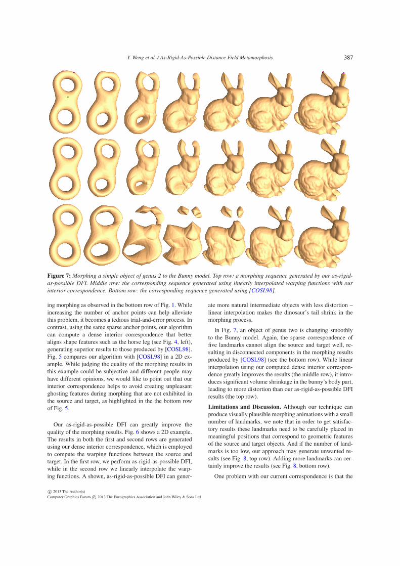
Figure 7: Morphing a simple object of genus 2 to the Bunny model. Top row: a morphing sequence generated by our as-rigid-
as-possible DFI. Middle row: the corresponding sequence generated using linearly interpolated warping functions with our
interior correspondence. Bottom row: the corresponding sequence generated using [COSL98].
ing morphing as observed in the bottom row of Fig. 1. Whileincreasing the number of anchor points can help alleviatethis problem, it becomes a tedious trial-and-error process. Incontrast, using the same sparse anchor points, our algorithmcan compute a dense interior correspondence that betteraligns shape features such as the horse leg (see Fig. 4, left),generating superior results to those produced by [COSL98].Fig. 5 compares our algorithm with [COSL98] in a 2D ex-ample. While judging the quality of the morphing results inthis example could be subjective and different people mayhave different opinions, we would like to point out that ourinterior correspondence helps to avoid creating unpleasantghosting features during morphing that are not exhibited inthe source and target, as highlighted in the the bottom rowof Fig. 5.
Our as-rigid-as-possible DFI can greatly improve thequality of the morphing results. Fig. 6 shows a 2D example.The results in both the first and second rows are generatedusing our dense interior correspondence, which is employedto compute the warping functions between the source andtarget. In the first row, we perform as-rigid-as-possible DFI,while in the second row we linearly interpolate the warp-ing functions. A shown, as-rigid-as-possible DFI can gener-
ate more natural intermediate objects with less distortion –linear interpolation makes the dinosaur’s tail shrink in themorphing process.
In Fig. 7, an object of genus two is changing smoothlyto the Bunny model. Again, the sparse correspondence offive landmarks cannot align the source and target well, re-sulting in disconnected components in the morphing resultsproduced by [COSL98] (see the bottom row). While linearinterpolation using our computed dense interior correspon-dence greatly improves the results (the middle row), it intro-duces significant volume shrinkage in the bunny’s body part,leading to more distortion than our as-rigid-as-possible DFIresults (the top row).
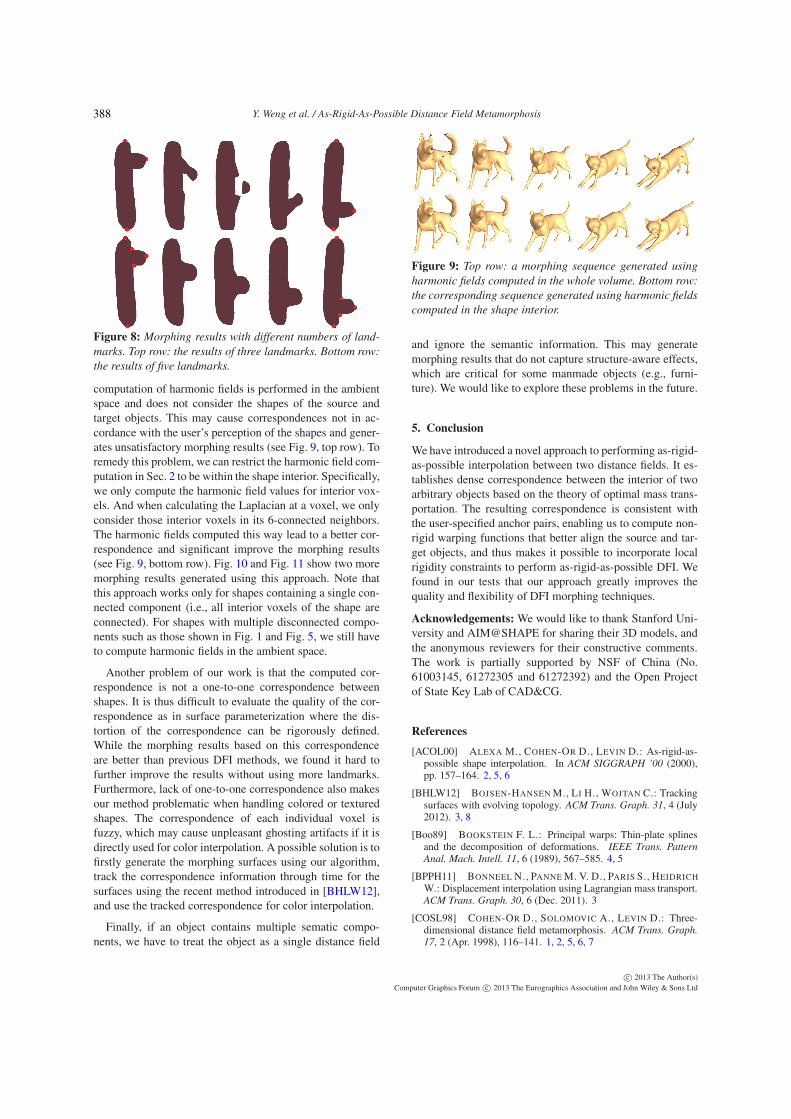
Limitations and Discussion. Although our technique canproduce visually plausible morphing animations with a smallnumber of landmarks, we note that in order to get satisfac-tory results these landmarks need to be carefully placed inmeaningful positions that correspond to geometric featuresof the source and target objects. And if the number of land-marks is too low, our approach may generate unwanted re-sults (see Fig. 8, top row). Adding more landmarks can cer-tainly improve the results (see Fig. 8, bottom row).
One problem with our current correspondence is that the
c© 2013 The Author(s)
Computer Graphics Forum c© 2013 The Eurographics Association and John Wiley & Sons Ltd
387
Y. Weng et al. / As-Rigid-As-Possible Distance Field Metamorphosis
Figure 8: Morphing results with different numbers of land-
marks. Top row: the results of three landmarks. Bottom row:
the results of five landmarks.
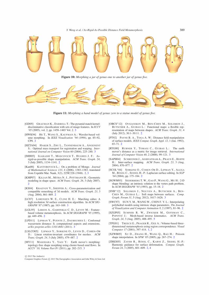
computation of harmonic fields is performed in the ambientspace and does not consider the shapes of the source andtarget objects. This may cause correspondences not in ac-cordance with the user’s perception of the shapes and gener-ates unsatisfactory morphing results (see Fig. 9, top row). Toremedy this problem, we can restrict the harmonic field com-putation in Sec. 2 to be within the shape interior. Specifically,we only compute the harmonic field values for interior vox-els. And when calculating the Laplacian at a voxel, we onlyconsider those interior voxels in its 6-connected neighbors.The harmonic fields computed this way lead to a better cor-respondence and significant improve the morphing results(see Fig. 9, bottom row). Fig. 10 and Fig. 11 show two moremorphing results generated using this approach. Note thatthis approach works only for shapes containing a single con-nected component (i.e., all interior voxels of the shape areconnected). For shapes with multiple disconnected compo-nents such as those shown in Fig. 1 and Fig. 5, we still haveto compute harmonic fields in the ambient space.
Another problem of our work is that the computed cor-respondence is not a one-to-one correspondence betweenshapes. It is thus difficult to evaluate the quality of the cor-respondence as in surface parameterization where the dis-tortion of the correspondence can be rigorously defined.While the morphing results based on this correspondenceare better than previous DFI methods, we found it hard tofurther improve the results without using more landmarks.Furthermore, lack of one-to-one correspondence also makesour method problematic when handling colored or texturedshapes. The correspondence of each individual voxel isfuzzy, which may cause unpleasant ghosting artifacts if it isdirectly used for color interpolation. A possible solution is tofirstly generate the morphing surfaces using our algorithm,track the correspondence information through time for thesurfaces using the recent method introduced in [BHLW12],and use the tracked correspondence for color interpolation.
Finally, if an object contains multiple sematic compo-nents, we have to treat the object as a single distance field
Figure 9: Top row: a morphing sequence generated using
harmonic fields computed in the whole volume. Bottom row:
the corresponding sequence generated using harmonic fields
computed in the shape interior.
and ignore the semantic information. This may generatemorphing results that do not capture structure-aware effects,which are critical for some manmade objects (e.g., furni-ture). We would like to explore these problems in the future.
5. Conclusion
We have introduced a novel approach to performing as-rigid-as-possible interpolation between two distance fields. It es-tablishes dense correspondence between the interior of twoarbitrary objects based on the theory of optimal mass trans-portation. The resulting correspondence is consistent withthe user-specified anchor pairs, enabling us to compute non-rigid warping functions that better align the source and tar-get objects, and thus makes it possible to incorporate localrigidity constraints to perform as-rigid-as-possible DFI. Wefound in our tests that our approach greatly improves thequality and flexibility of DFI morphing techniques.
Acknowledgements: We would like to thank Stanford Uni-versity and AIM@SHAPE for sharing their 3D models, andthe anonymous reviewers for their constructive comments.The work is partially supported by NSF of China (No.61003145, 61272305 and 61272392) and the Open Projectof State Key Lab of CAD&CG.
References
[ACOL00] ALEXA M., COHEN-OR D., LEVIN D.: As-rigid-as-possible shape interpolation. In ACM SIGGRAPH ’00 (2000),pp. 157–164. 2, 5, 6
[BHLW12] BOJSEN-HANSEN M., LI H., WOJTAN C.: Trackingsurfaces with evolving topology. ACM Trans. Graph. 31, 4 (July2012). 3, 8
[Boo89] BOOKSTEIN F. L.: Principal warps: Thin-plate splinesand the decomposition of deformations. IEEE Trans. Pattern
Anal. Mach. Intell. 11, 6 (1989), 567–585. 4, 5
[BPPH11] BONNEEL N., PANNE M. V. D., PARIS S., HEIDRICH
W.: Displacement interpolation using Lagrangian mass transport.ACM Trans. Graph. 30, 6 (Dec. 2011). 3
[COSL98] COHEN-OR D., SOLOMOVIC A., LEVIN D.: Three-dimensional distance field metamorphosis. ACM Trans. Graph.
17, 2 (Apr. 1998), 116–141. 1, 2, 5, 6, 7
c© 2013 The Author(s)
Computer Graphics Forum c© 2013 The Eurographics Association and John Wiley & Sons Ltd
388
Y. Weng et al. / As-Rigid-As-Possible Distance Field Metamorphosis
Figure 10: Morphing a jar of genus one to another jar of genus five.
Figure 11: Morphing a hand model of genus zero to a statue model of genus five.
[GD05] GRAUMAN K., DARRELL T.: The pyramid match kernel:discriminative classification with sets of image features. In ICCV
’05 (2005), vol. 2, pp. 1458–1465 Vol. 2. 3
[HWK94] HE T., WANG S., KAUFMAN A.: Wavelet-based vol-ume morphing. In IEEE Visualization ’94 (1994), pp. 85–92,CP8. 2
[HZTA04] HAKER S., ZHU L., TANNENBAUM A., ANGENENT
S.: Optimal mass transport for registration and warping. Inter-
national Journal on Computer Vision 60 (2004), 225–240. 3
[IMH05] IGARASHI T., MOSCOVICH T., HUGHES J. F.: As-rigid-as-possible shape manipulation. ACM Trans. Graph. 24,3 (July 2005), 1134–1141. 2
[Kan06] KANTOROVICH L.: On a problem of Monge. Journal
of Mathematical Sciences 133, 4 (2006), 1383–1383, translatedfrom Uspekhi Mat. Nauk, 3(2), 225lC226 (1948). 2, 3
[KMP07] KILIAN M., MITRA N. J., POTTMANN H.: Geometricmodeling in shape space. ACM Trans. Graph. 26, 3 (July 2007).2
[KS04] KRAEVOY V., SHEFFER A.: Cross-parameterization andcompatible remeshing of 3d models. ACM Trans. Graph. 23, 3(Aug. 2004), 861–869. 2
[LC87] LORENSEN W. E., CLINE H. E.: Marching cubes: Ahigh resolution 3d surface construction algorithm. In ACM SIG-
GRAPH ’87 (1987), pp. 163–169. 3
[LGL95] LERIOS A., GARFINKLE C. D., LEVOY M.: Feature-based volume metamorphosis. In ACM SIGGRAPH ’95 (1995),pp. 449–456. 2
[LPD11] LIPMAN Y., PUENTE J., DAUBECHIES I.: Conformalwasserstein distance: Ii. computational aspects and extensions.arXiv preprint arXiv:1103.4681 (2011). 3
[LSLCO05] LIPMAN Y., SORKINE O., LEVIN D., COHEN-OR
D.: Linear rotation-invariant coordinates for meshes. ACM
Trans. Graph. 24, 3 (July 2005), 479–487. 2
[MY11] MAKIHARA Y., YAGI Y.: Earth mover’s morphing:topology-free shape morphing using cluster-based emd flows. InACCV ’10, Volume Part IV (2011), pp. 202–215. 3
[OBCS∗12] OVSJANIKOV M., BEN-CHEN M., SOLOMON J.,BUTSCHER A., GUIBAS L.: Functional maps: a flexible rep-resentation of maps between shapes. ACM Trans. Graph. 31, 4(July 2012), 30:1–30:11. 2
[PT92] PAYNE B. A., TOGA A. W.: Distance field manipulationof surface models. IEEE Comput. Graph. Appl. 12, 1 (Jan. 1992),65–71. 2
[RTG00] RUBNER Y., TOMASI C., GUIBAS L.: The earthmover’s distance as a metric for image retrieval. International
Journal of Computer Vision 40, 2 (2000), 99–121. 3
[SAPH04] SCHREINER J., ASIRVATHAM A., PRAUN E., HOPPE
H.: Inter-surface mapping. ACM Trans. Graph. 23, 3 (Aug.2004), 870–877. 2
[SCOL∗04] SORKINE O., COHEN-OR D., LIPMAN Y., ALEXA
M., RÖSSL C., SEIDEL H.-P.: Laplacian surface editing. In SGP
’04 (2004), pp. 175–184. 2
[SGWM93] SEDERBERG T. W., GAO P., WANG G., MU H.: 2-Dshape blending: an intrinsic solution to the vertex path problem.In ACM SIGGRAPH ’93 (1993), pp. 15–18. 2
[SNB∗12] SOLOMON J., NGUYEN A., BUTSCHER A., BEN-CHEN M., GUIBAS L.: Soft maps between surfaces. Comp.
Graph. Forum 31, 5 (Aug. 2012), 1617–1626. 3
[SWC97] SUN Y. M., WANG W., CHIN F. Y. L.: Interpolatingpolyhedral models using intrinsic shape parameters. The Journal
of Visualization and Computer Animation 8, 2 (1997), 81–96. 2
[SZGP05] SUMNER R. W., ZWICKER M., GOTSMAN C.,POPOVIC J.: Mesh-based inverse kinematics. ACM Trans.
Graph. 24, 3 (Aug. 2005), 488–495. 5
[TPG01] TREECE G., PRAGER R., GEE A.: Volume-based three-dimensional metamorphosis using region correspondence. Visual
Computer 17 (2001), 397–414. 1, 2
[XZWB05] XU D., ZHANG H., WANG Q., BAO H.: Poissonshape interpolation. In SPM ’05 (2005), pp. 267–274. 2
[ZRKS05] ZAYER R., RÖSSL C., KARNI Z., SEIDEL H.-P.:Harmonic guidance for surface deformation. Comput. Graph.
Forum 24, 3 (2005), 601–609. 2, 4
c© 2013 The Author(s)
Computer Graphics Forum c© 2013 The Eurographics Association and John Wiley & Sons Ltd
389