Embed Size (px)
Citation preview

1
www.pilotwww.pilot--rc.comrc.com
Wingspan: 88 in
Wingarea: 1479.8 sp in
Length: 78.8 in
Engine: 50CC
Assembly Manual for
Decathlon 107”Decathlon 107”--180”180”

2
INTRODUCTION
Thank you for purchasing our Decathlon plane. At Pilot we strive to build the best performing Quick Build ARF aircraft available today.
The Decathlon is manufactured using advanced building techniques for maximum strength and lightest weight. The kit features many premium light weight carbon fiber components, hardware, genuine Oracover(Ultracote) covering, laser cut wood, and the best adhesives. The Decathlon’s light weight allows optimum flight performance from exciting aerobatics or just relaxing.
At Pilot we make every effort to provide the highest quality products and customer service. Our goal is a happy customer having a wonderful time assembling and flying Pilot model aircraft.
More information on website
www.pilotwww.pilot--rc.comrc.com
3
WARRANTYWARRANTY
■ All Pilot-RC products are guaranteed against defects for 30 days of receiving your airplane. This warranty is limited to construction or production defects in both material and workmanship , it does not cover any component parts damaged through use or modification .
■ The manufacture cannot supervise the assembly, operation or maintenance, and is not responsible for radio malfunctions. Please ensure your radio system is in good condition. We are not responsible for any accident or damage while using this product. It isimpossible to determine for certain whether crash damage was the result of improper installation of our products, a radio system failure, or pilot error. Model airplane owners use our products at their own risk.
■ Pilot-RC will not be liable for any costs, unless agreed and proved beyond doubt the failure was due to faulty materials or fabrication. Any agreed cost will not exceed the cost of the airframe and not include engine, radio equipment or third party claims.
■ Should you wish to return a product or receive replacement parts, all shipping cost must be paid by the customer.
4
ATTENTIONATTENTION
Email: [email protected] , [email protected]:+86 760 88781293FAX: +86 760 88780293Address: No.34, Chengnan Er Road , Zhongshan city, 528400, Guangdong Province, China
■ Do not regard this plane as a toy!■ To ensure safety, please read the instruction manual thoroughly before assembly.■ Building and operating an RC Plane of this nature requires previous experience and competence to an experienced level. This plane is not for a beginner!■ If you are in doubt have an experienced pilot at hand. Diligent practicing and correct guidance is essential, accidents can cause bodily harm and property damage. ■ Seek assistance from an experienced person or airplane model clubs in assembly, operation and maintenance to ensure successful training.■ Fly only in a registered RC model club airfield that is approved by your local Academy of Model Aeronautics (AMA).
Pilot-RC has the right to revise the plane, the instructions and the limited warranty without
notice. If you have any problems and questions please contact Pilot –RC at:
5
Introduction………………….………..….…….…………
Warranty…………………….……..….…..……………….. Attention…………….…………..….……..………………..
FuselageRudder Assembly
Rudder Control Horns………..…….…...……………. Tail Wheel Installation…………..…….......................
Landing Gear Assembly .Main Landing Gear Installation………….…..………. Pants Installation…………..….……………………….
Servos Wing Servo Assembly
Servo Arm Installation………….….…………………. Aileron Control Horns………….……….…………….. Servo Installation…….…………..……………………
Rudder Servo AssemblyServo Tray Installation….…….….......……………… Servo Installation……….….……...………………….
Elevator Servo AssemblyServo Arm Installation………….……………………. Elevator Control Horns……………....….…………… Servo Installation……………….....………………….
Engine installation Firewall Assembly……….…….....………………….. Engine Assembly……….…..……..…………………. Throttle Servo Assembly….….…...…….…………… Ignition Module………….…….……………………… Hatch And Fuel Tank………….….……....…………..
Final AssemblySwitch Assembly………….….……....……………….Wing Assembly………….….……....…………………Elevator Assembly……………….….……....………..CG And Control Throws……………………………… Flight Preparation…...…………….….…..…………..Led Option…..………….….……....………………….
INDEX
2
3
4
17
19
68
1011
131415
232425
28
3029
3132
34
3739
4240
35
6
Fuselage
Rudder Assembly
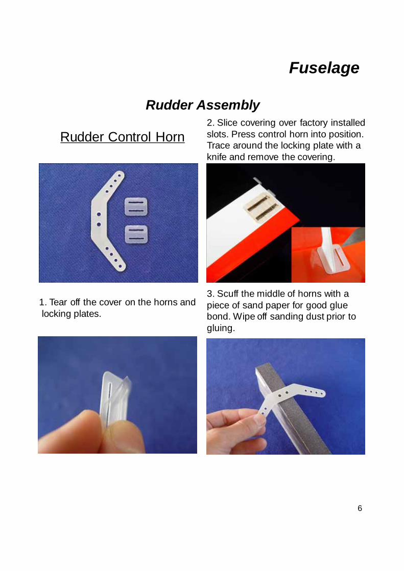
Rudder Control Horn
1. Tear off the cover on the horns and locking plates.
2. Slice covering over factory installed slots. Press control horn into position. Trace around the locking plate with a knife and remove the covering.
3. Scuff the middle of horns with a piece of sand paper for good glue bond. Wipe off sanding dust prior to gluing.
7
Rudder Assembly
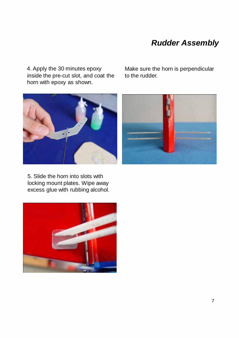
4. Apply the 30 minutes epoxy inside the pre-cut slot, and coat the horn with epoxy as shown.
Make sure the horn is perpendicular to the rudder.
5. Slide the horn into slots with locking mount plates. Wipe away excess glue with rubbing alcohol.
8
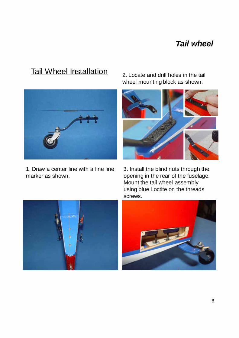
Tail Wheel Installation
Tail wheel
1. Draw a center line with a fine line marker as shown.
3. Install the blind nuts through the opening in the rear of the fuselage. Mount the tail wheel assembly using blue Loctite on the threads screws.
2. Locate and drill holes in the tail wheel mounting block as shown.
9
Tail wheel
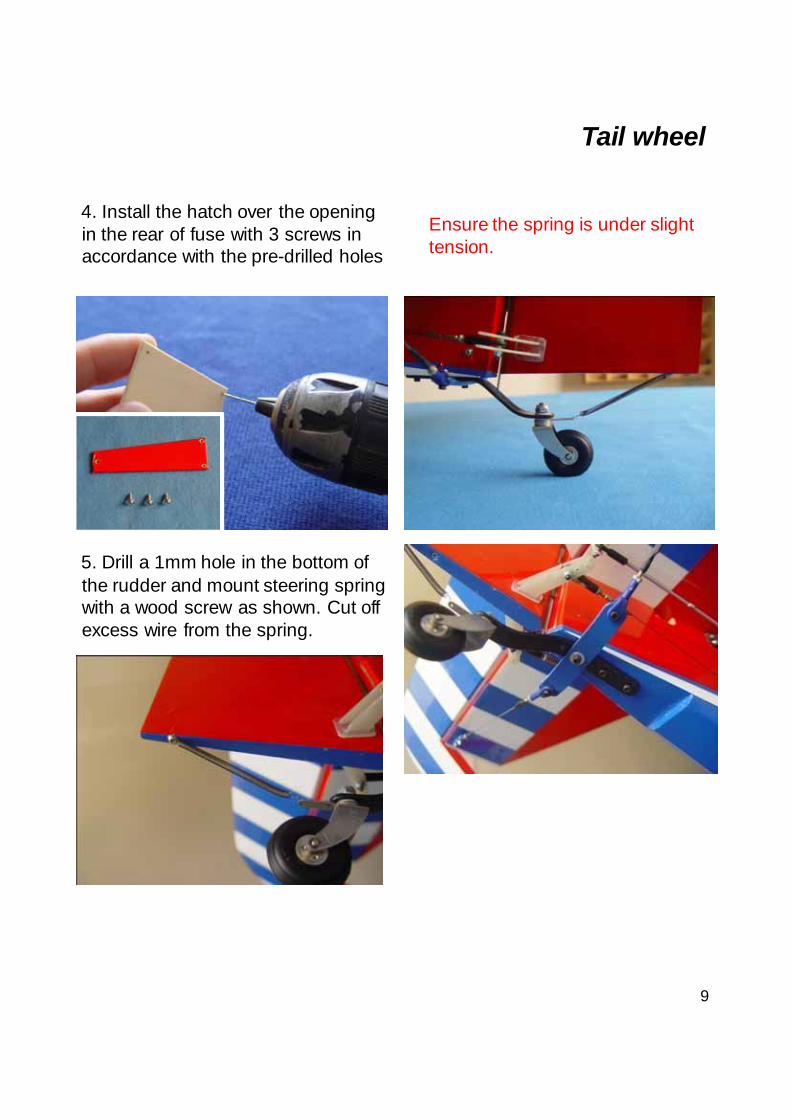
5. Drill a 1mm hole in the bottom of the rudder and mount steering spring with a wood screw as shown. Cut off excess wire from the spring.
4. Install the hatch over the opening in the rear of fuse with 3 screws in accordance with the pre-drilled holes
Ensure the spring is under slight tension.
10
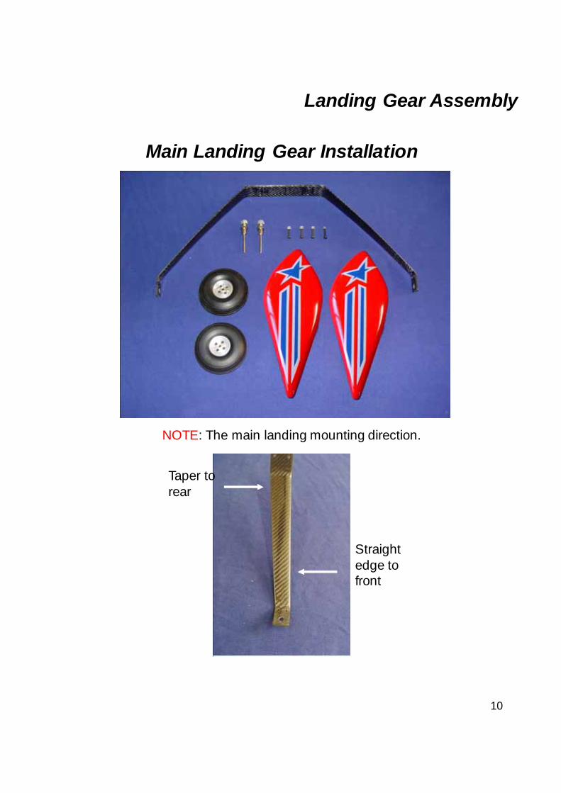
Main Landing Gear Installation
Landing Gear Assembly
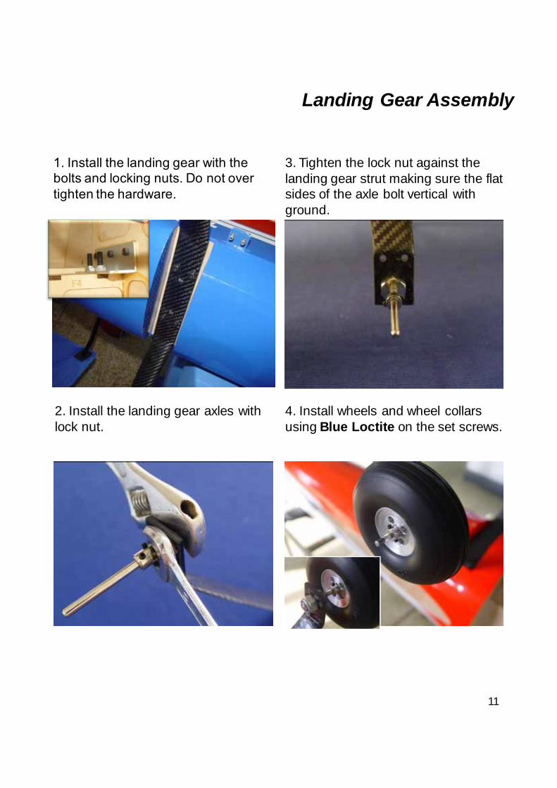
NOTE: The main landing mounting direction.
Taper to rear
Straight edge to front
11
Landing Gear Assembly
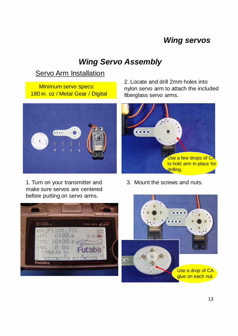
2. Install the landing gear axles with lock nut.
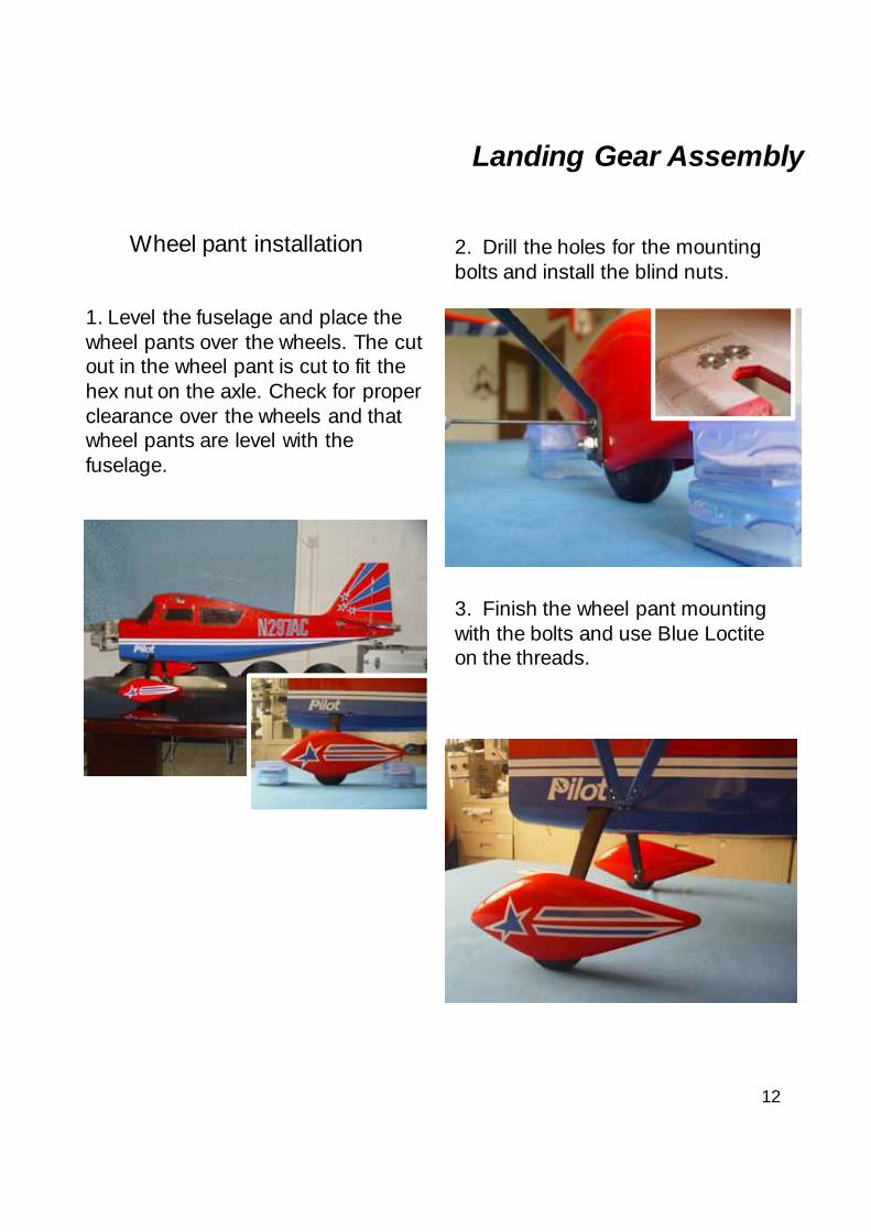
4. Install wheels and wheel collars using Blue Loctite on the set screws.
3. Tighten the lock nut against the landing gear strut making sure the flat sides of the axle bolt vertical with ground.
1. Install the landing gear with the bolts and locking nuts. Do not over tighten the hardware.
12
Landing Gear Assembly
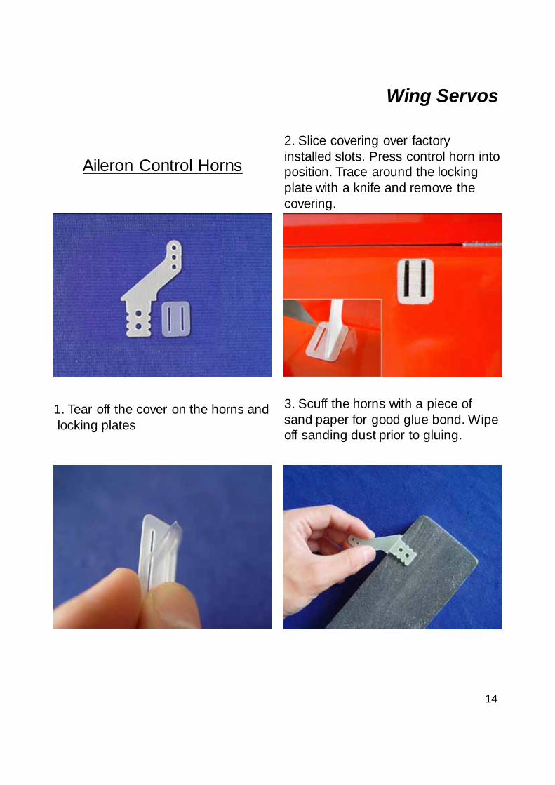
1. Level the fuselage and place the wheel pants over the wheels. The cut out in the wheel pant is cut to fit the hex nut on the axle. Check for proper clearance over the wheels and that wheel pants are level with the fuselage.
2. Drill the holes for the mounting bolts and install the blind nuts.
3. Finish the wheel pant mounting with the bolts and use Blue Loctite on the threads.
Wheel pant installation
13
Wing servos
Wing Servo Assembly
Minimum servo specs:
Servo Arm Installation
1. Turn on your transmitter and make sure servos are centered before putting on servo arms.
2. Locate and drill 2mm holes into nylon servo arm to attach the included fiberglass servo arms.
3. Mount the screws and nuts.
180 in. oz / Metal Gear / Digital
Use a drop of CA glue on each nut.
Use a few drops of CA to hold arm in place for drilling.
14
Aileron Control Horns
1. Tear off the cover on the horns and locking plates
2. Slice covering over factory installed slots. Press control horn into position. Trace around the locking plate with a knife and remove the covering.
3. Scuff the horns with a piece of sand paper for good glue bond. Wipe off sanding dust prior to gluing.
Wing Servos
15
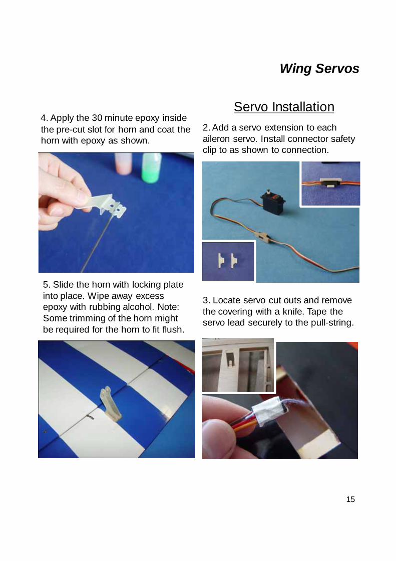
4. Apply the 30 minute epoxy inside the pre-cut slot for horn and coat the horn with epoxy as shown.
5. Slide the horn with locking plate into place. Wipe away excess epoxy with rubbing alcohol. Note: Some trimming of the horn might be required for the horn to fit flush.
Servo Installation
Wing Servos
2. Add a servo extension to each aileron servo. Install connector safety clip to as shown to connection.
3. Locate servo cut outs and remove the covering with a knife. Tape the servo lead securely to the pull-string.
16
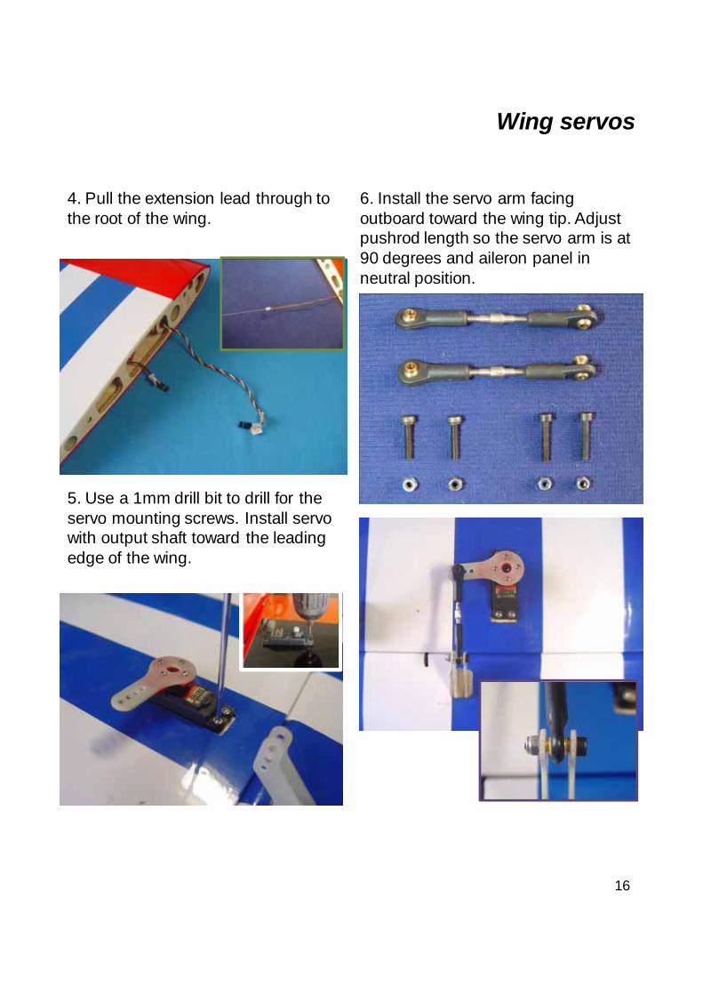
4. Pull the extension lead through to the root of the wing.
5. Use a 1mm drill bit to drill for the servo mounting screws. Install servo with output shaft toward the leading edge of the wing.
Wing servos
6. Install the servo arm facing outboard toward the wing tip. Adjust pushrod length so the servo arm is at 90 degrees and aileron panel in neutral position.
17
Rudder servo Assembly
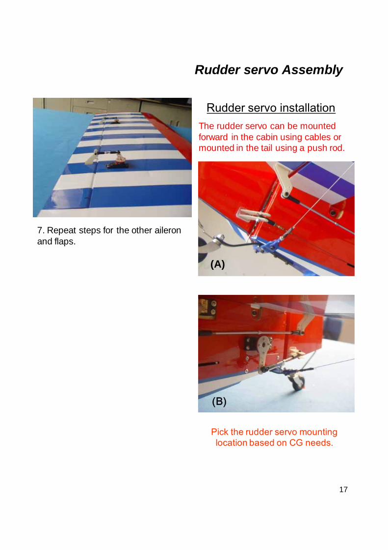
Rudder servo installationThe rudder servo can be mounted forward in the cabin using cables or mounted in the tail using a push rod.
(A)
(B)
7. Repeat steps for the other aileron and flaps.
Pick the rudder servo mounting location based on CG needs.
(B)
18
Rudder Servo Assembly
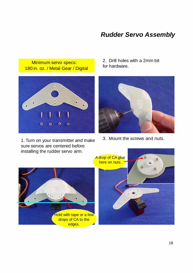
1. Turn on your transmitter and make sure servos are centered before installing the rudder servo arm.
2. Drill holes with a 2mm bit for hardware.
A drop of CA glue here on nuts.
3. Mount the screws and nuts.
Minimum servo specs:180 in. oz. / Metal Gear / Digital
Hold with tape or a few drops of CA to the
edges.
19
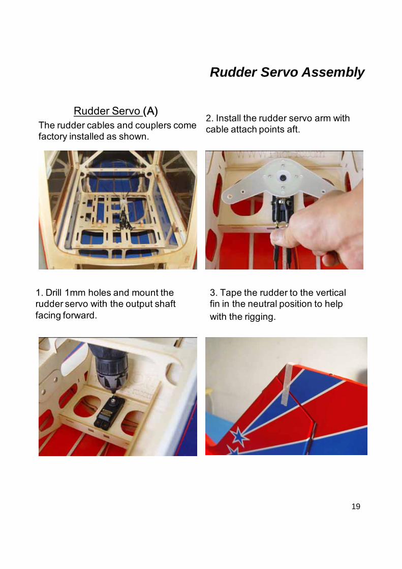
2. Install the rudder servo arm with cable attach points aft.
Rudder Servo Assembly
The rudder cables and couplers come factory installed as shown.
Rudder Servo (A)
1. Drill 1mm holes and mount the rudder servo with the output shaft facing forward.
3. Tape the rudder to the vertical fin in the neutral position to help with the rigging.
20
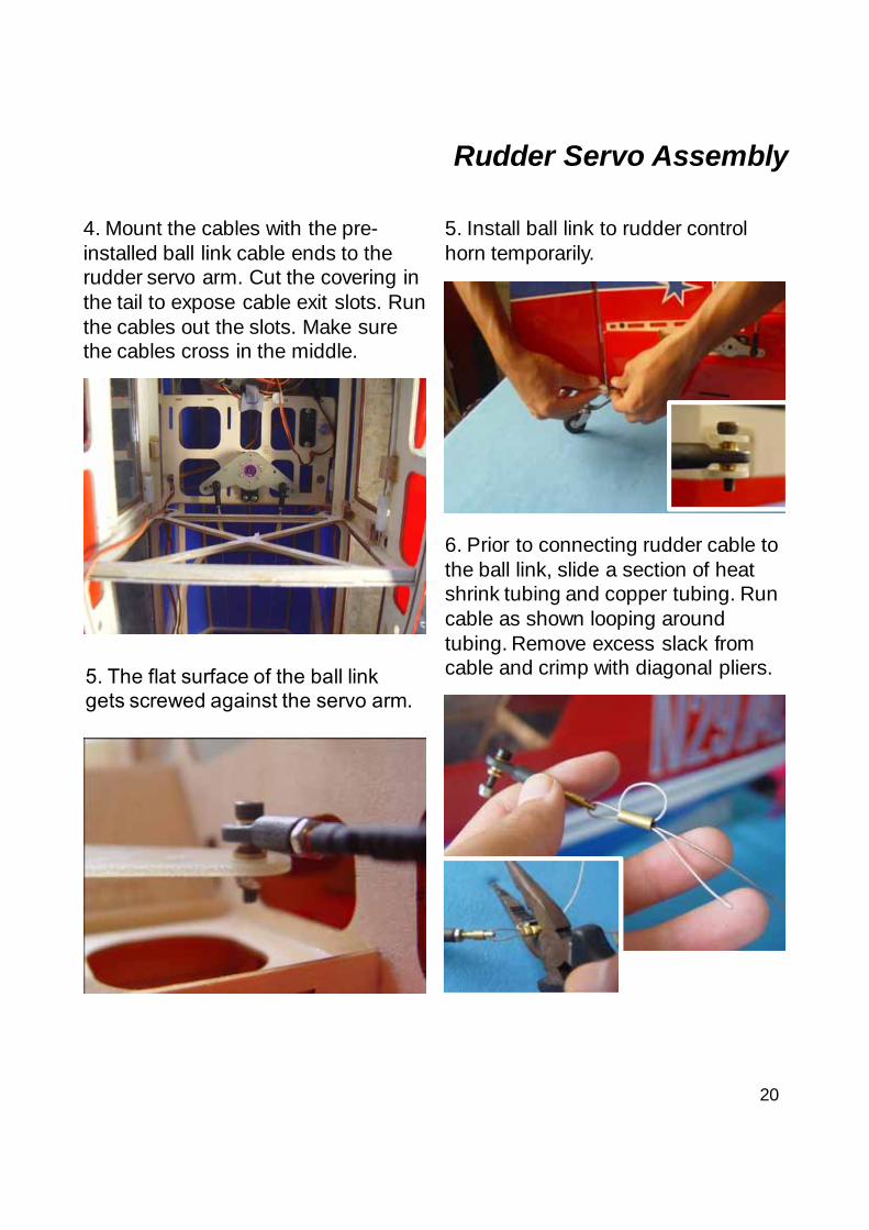
4. Mount the cables with the pre-installed ball link cable ends to the rudder servo arm. Cut the covering in the tail to expose cable exit slots. Run the cables out the slots. Make sure the cables cross in the middle.
5. Install ball link to rudder control horn temporarily.
6. Prior to connecting rudder cable to the ball link, slide a section of heat shrink tubing and copper tubing. Run cable as shown looping around tubing. Remove excess slack from cable and crimp with diagonal pliers.
Rudder Servo Assembly
5. The flat surface of the ball link gets screwed against the servo arm.
21
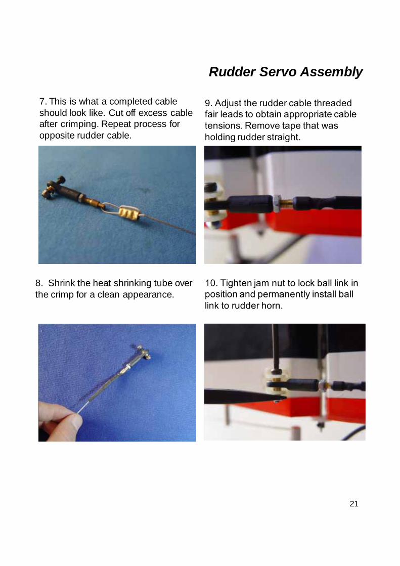
7. This is what a completed cable should look like. Cut off excess cable after crimping. Repeat process for opposite rudder cable.
9. Adjust the rudder cable threaded fair leads to obtain appropriate cable tensions. Remove tape that was holding rudder straight.
10..
Rudder Servo Assembly
8. Shrink the heat shrinking tube over the crimp for a clean appearance.
10. Tighten jam nut to lock ball link in position and permanently install ball link to rudder horn.
22
Rudder Servo Assembly
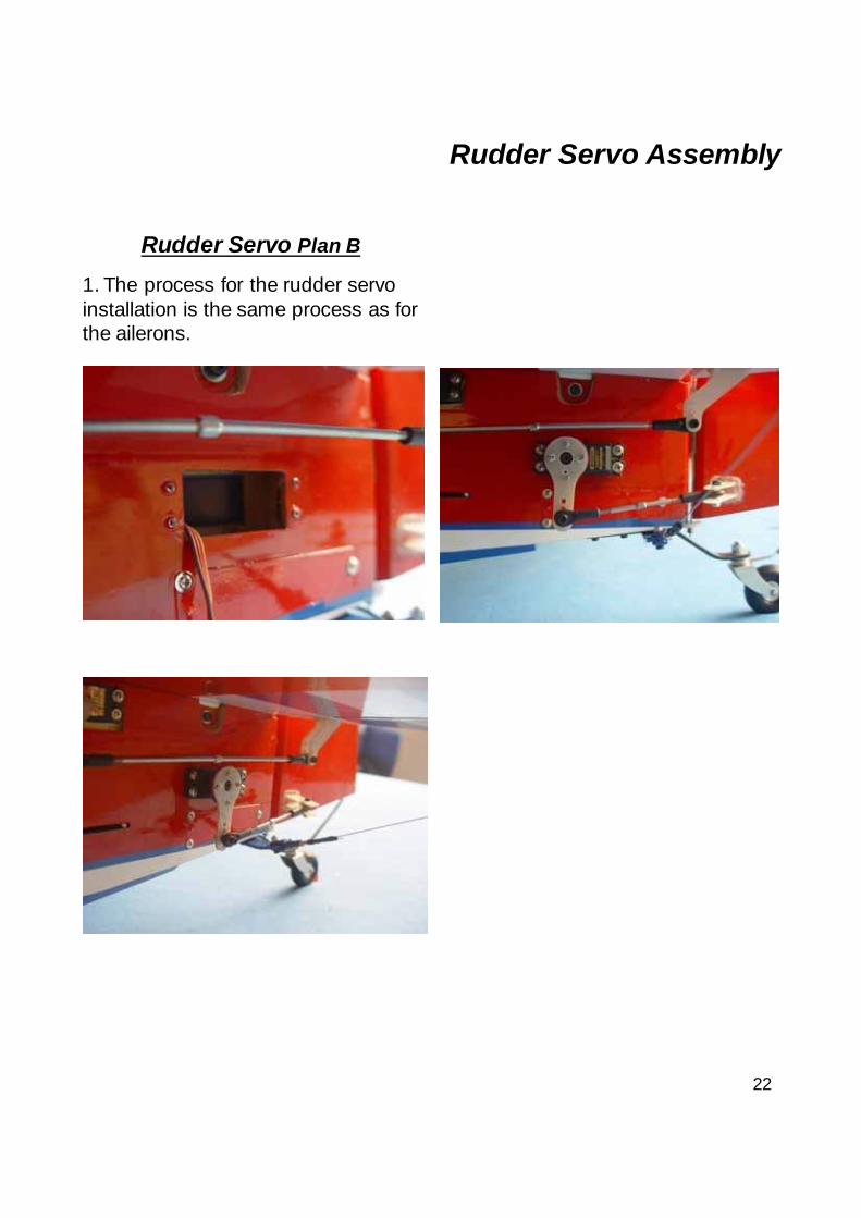
Rudder Servo Plan B
1. The process for the rudder servo installation is the same process as for the ailerons.
23
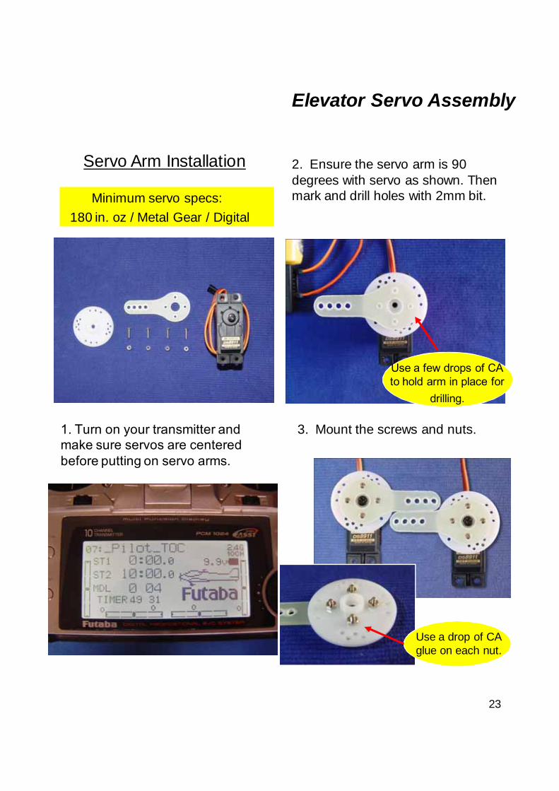
Elevator Servo Assembly
Minimum servo specs:
1. Turn on your transmitter and make sure servos are centered before putting on servo arms.
2. Ensure the servo arm is 90 degrees with servo as shown. Then mark and drill holes with 2mm bit.
3. Mount the screws and nuts.
180 in. oz / Metal Gear / Digital
Use a drop of CA glue on each nut.
Servo Arm Installation
Use a few drops of CA to hold arm in place for
drilling.
24
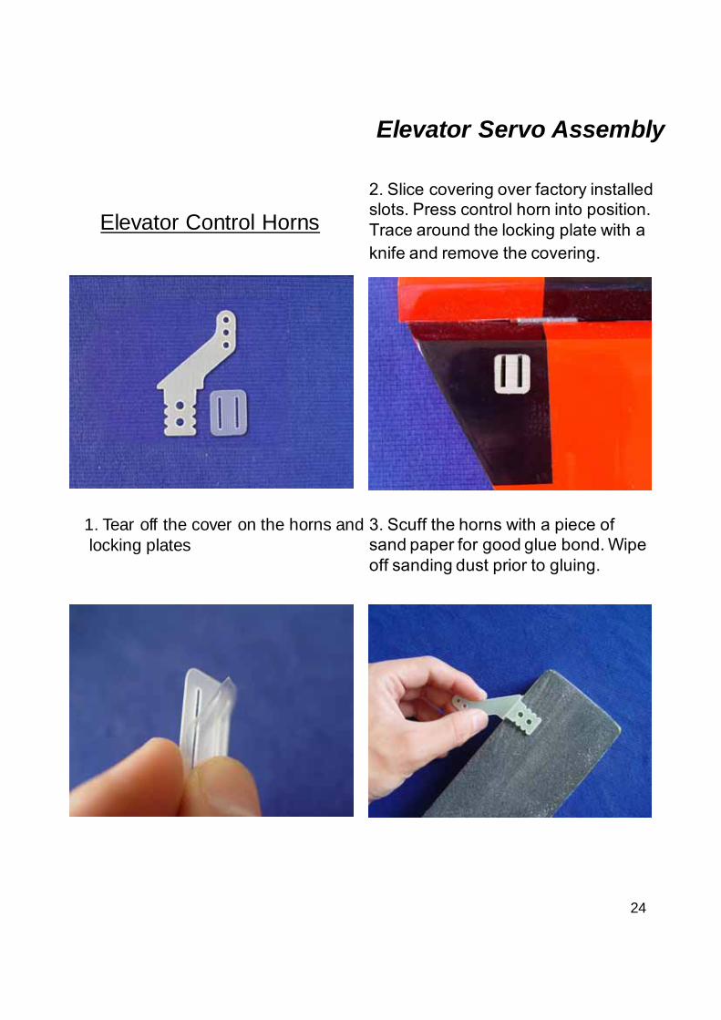
Elevator Control Horns
1. Tear off the cover on the horns and locking plates
2. Slice covering over factory installed slots. Press control horn into position. Trace around the locking plate with a knife and remove the covering.
3. Scuff the horns with a piece of sand paper for good glue bond. Wipe off sanding dust prior to gluing.
Elevator Servo Assembly
25
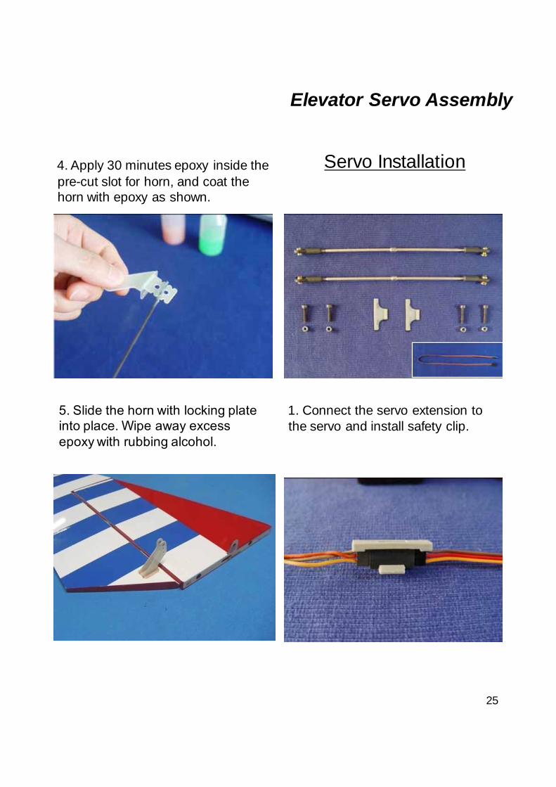
4. Apply 30 minutes epoxy inside the pre-cut slot for horn, and coat the horn with epoxy as shown.
Servo Installation
Elevator Servo Assembly
1. Connect the servo extension to the servo and install safety clip.
5. Slide the horn with locking plate into place. Wipe away excess epoxy with rubbing alcohol.
26
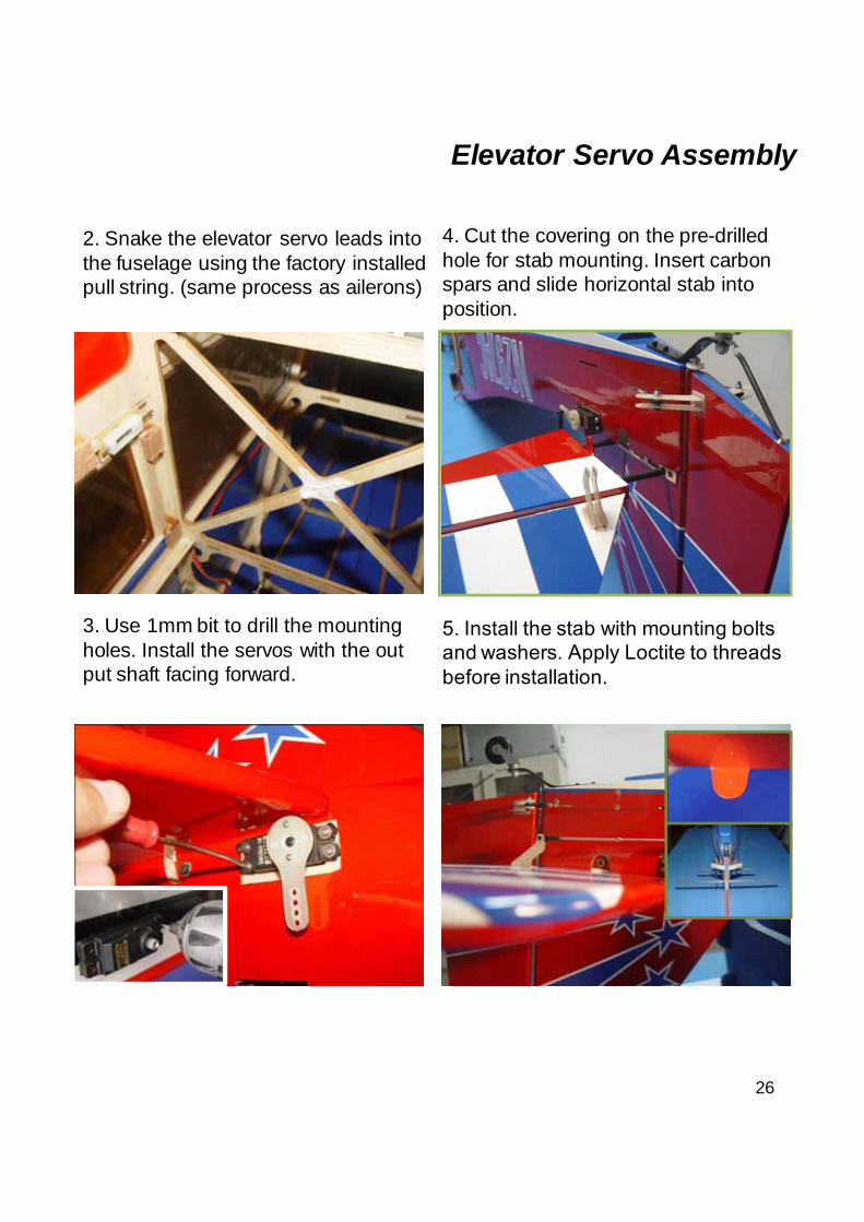
3. Use 1mm bit to drill the mounting holes. Install the servos with the out put shaft facing forward.
2. Snake the elevator servo leads into the fuselage using the factory installed pull string. (same process as ailerons)
4. Cut the covering on the pre-drilled hole for stab mounting. Insert carbon spars and slide horizontal stab into position.
Elevator Servo Assembly
5. Install the stab with mounting bolts and washers. Apply Loctite to threads before installation.
27
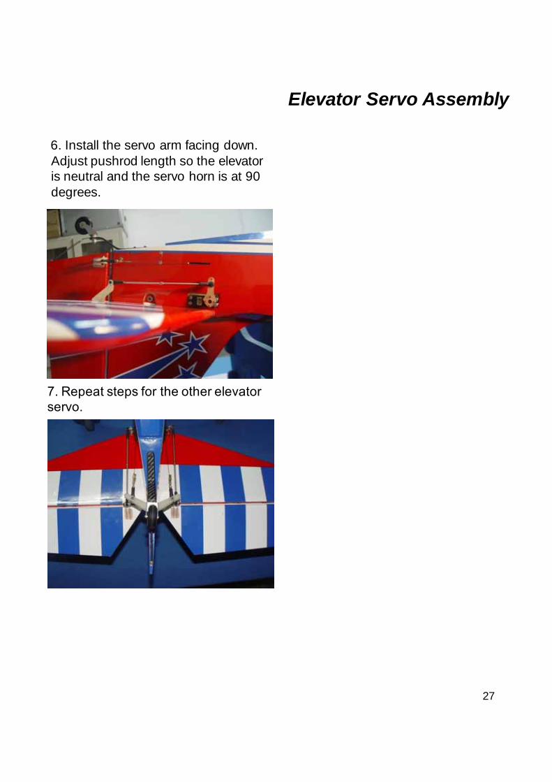
6. Install the servo arm facing down. Adjust pushrod length so the elevator is neutral and the servo horn is at 90 degrees.
Elevator Servo Assembly
7. Repeat steps for the other elevator servo.
28
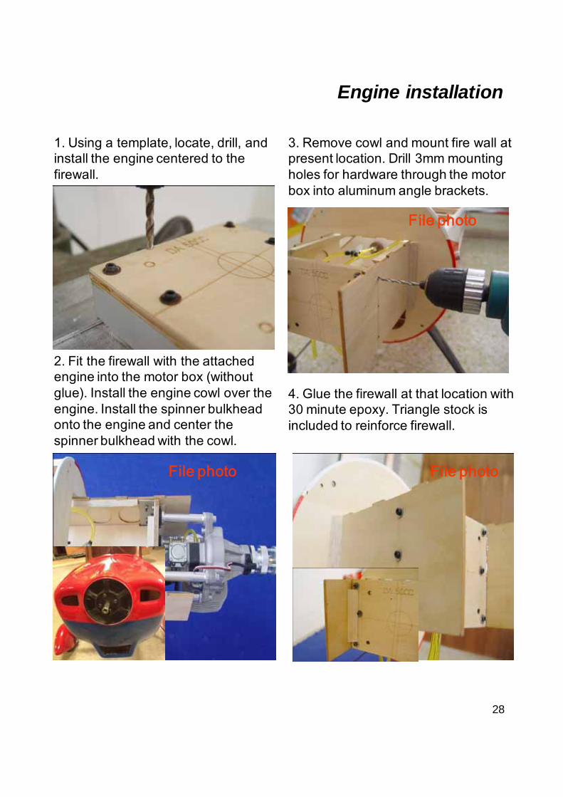
Engine installation
move
1. Using a template, locate, drill, and install the engine centered to the firewall.
2. Fit the firewall with the attached engine into the motor box (without glue). Install the engine cowl over the engine. Install the spinner bulkhead onto the engine and center the spinner bulkhead with the cowl.
3. Remove cowl and mount fire wall at present location. Drill 3mm mounting holes for hardware through the motor box into aluminum angle brackets.
File photo
4. Glue the firewall at that location with 30 minute epoxy. Triangle stock is included to reinforce firewall.
File photo
File photo
29
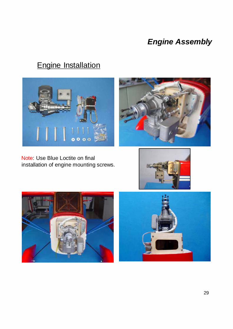
Engine Installation
Engine Assembly
Note: Use Blue Loctite on final installation of engine mounting screws.
30
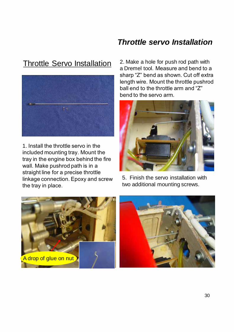
Throttle servo Installation
A drop of glue on nut
5. Finish the servo installation with two additional mounting screws.
Throttle Servo Installation
1. Install the throttle servo in the included mounting tray. Mount the tray in the engine box behind the fire wall. Make pushrod path is in a straight line for a precise throttle linkage connection. Epoxy and screw the tray in place.
2. Make a hole for push rod path with a Dremel tool. Measure and bend to a sharp “Z” bend as shown. Cut off extra length wire. Mount the throttle pushrod ball end to the throttle arm and “Z” bend to the servo arm.
31
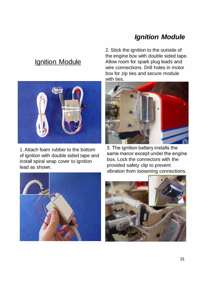
Ignition Module
Ignition Module
1. Attach foam rubber to the bottom of ignition with double sided tape and install spiral wrap cover to ignition lead as shown.
2. Stick the ignition to the outside of the engine box with double sided tape. Allow room for spark plug leads and wire connections. Drill holes in motor box for zip ties and secure module with ties.
3. The ignition battery installs the same manor except under the engine box. Lock the connectors with the provided safety clip to prevent vibration from loosening connections.
32
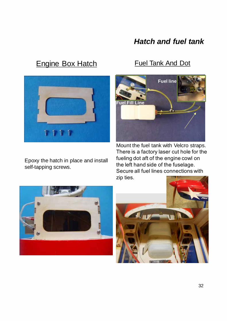
Engine Box Hatch
Epoxy the hatch in place and install self-tapping screws.
Fuel Tank And Dot
Mount the fuel tank with Velcro straps. There is a factory laser cut hole for the fueling dot aft of the engine cowl on the left hand side of the fuselage. Secure all fuel lines connections with zip ties.
Hatch and fuel tank
Fuel line
Fuel Fill Line
33
Cowl Assembly
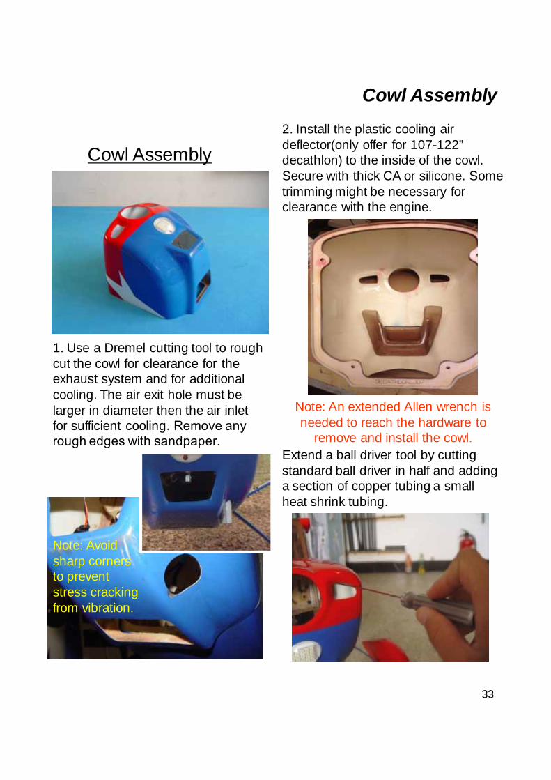
Cowl Assembly
1. Use a Dremel cutting tool to rough cut the cowl for clearance for the exhaust system and for additional cooling. The air exit hole must be larger in diameter then the air inlet for sufficient cooling. Remove any rough edges with sandpaper.
Note: Avoid sharp corners to prevent stress cracking from vibration.
Extend a ball driver tool by cutting standard ball driver in half and adding a section of copper tubing a small heat shrink tubing.
2. Install the plastic cooling air deflector(only offer for 107-122” decathlon) to the inside of the cowl. Secure with thick CA or silicone. Some trimming might be necessary for clearance with the engine.
Note: An extended Allen wrench is needed to reach the hardware to
remove and install the cowl.
34
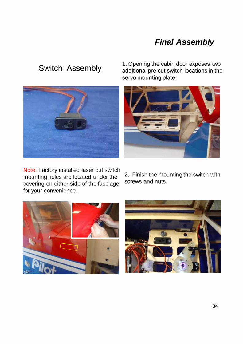
Switch Assembly
Note: Factory installed laser cut switch mounting holes are located under the covering on either side of the fuselage for your convenience.
2. Finish the mounting the switch with screws and nuts.
1. Opening the cabin door exposes two additional pre cut switch locations in the servo mounting plate.
Final Assembly
35
Wing Assembly
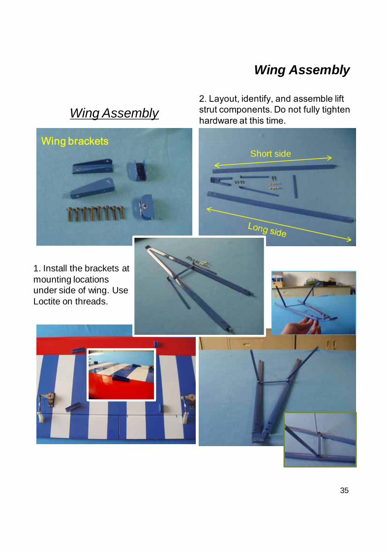
Wing Assembly
Short side
1. Install the brackets at mounting locations under side of wing. Use Loctite on threads.
Wing brackets
2. Layout, identify, and assemble lift strut components. Do not fully tighten hardware at this time.
36
Wing Assembly
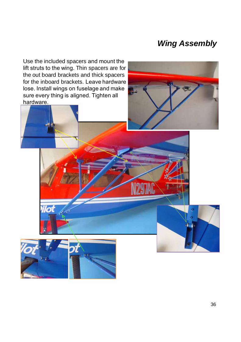
Use the included spacers and mount the lift struts to the wing. Thin spacers are for the out board brackets and thick spacers for the inboard brackets. Leave hardware lose. Install wings on fuselage and make sure every thing is aligned. Tighten all hardware.
37
Elevator Assembly
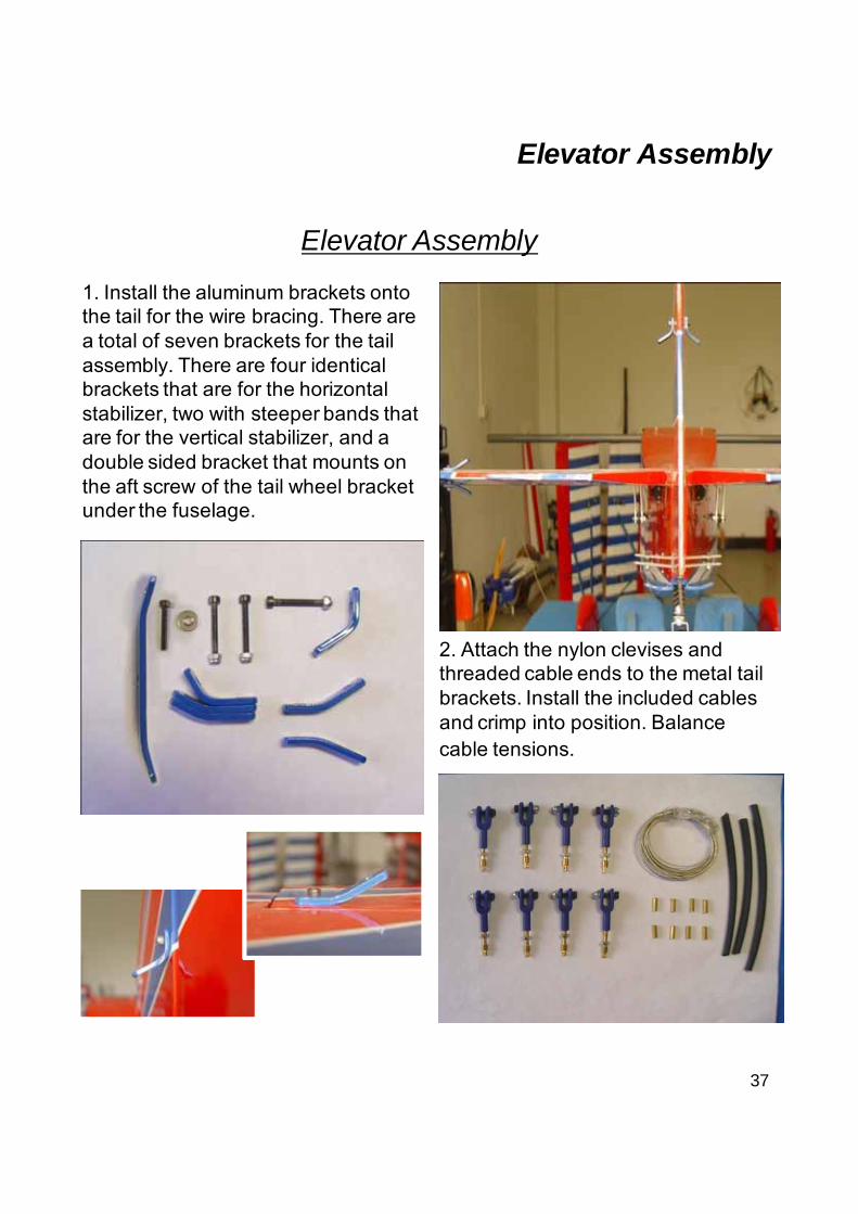
Elevator Assembly
1. Install the aluminum brackets onto the tail for the wire bracing. There are a total of seven brackets for the tail assembly. There are four identical brackets that are for the horizontal stabilizer, two with steeper bands that are for the vertical stabilizer, and a double sided bracket that mounts on the aft screw of the tail wheel bracket under the fuselage.
2. Attach the nylon clevises and threaded cable ends to the metal tail brackets. Install the included cables and crimp into position. Balance cable tensions.
38
Elevator Assembly
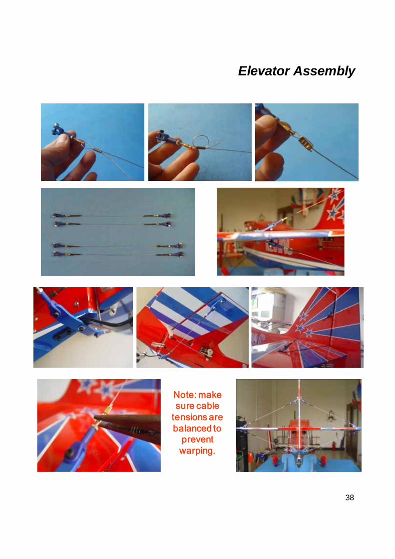
Note: make sure cable
tensions are balanced to
prevent warping.
39
CG And Control Throws
■After you have a few flights under you belt you can change control deflections based on personal preference as well as adjust the CG back in 1/4" intervals.
Elevator: 40 Degrees on High rate
12 Degrees on Low rate
Aileron: 30 Degrees on High rate
12 Degrees on Low rate
Rudder: 45 Degrees on High rate
40 Degrees on Low rate
Throttle: Adjust idle –full
■ Set exponential up to approximately 40% on your elevator to make great landings on low rates and 70% exponential on High Rate.
The First Flight set upCenter Of Gravity
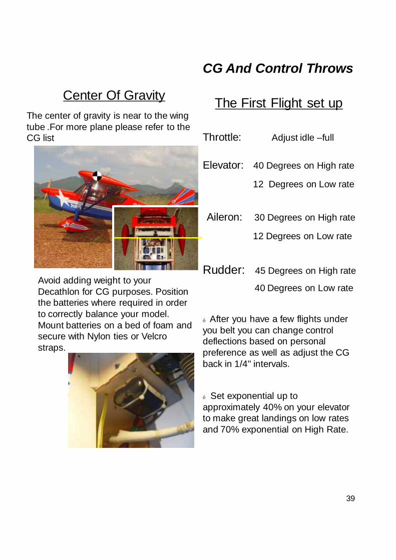
Avoid adding weight to your Decathlon for CG purposes. Position the batteries where required in order to correctly balance your model. Mount batteries on a bed of foam and secure with Nylon ties or Velcro straps.
The center of gravity is near to the wing tube .For more plane please refer to the CG list
Center of gravity
40
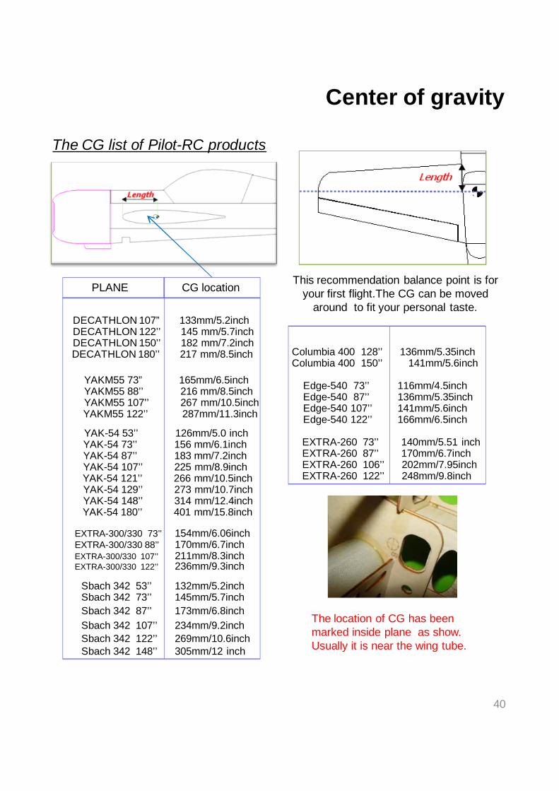
EXTRA-300/330 73’’ 154mm/6.06inch EXTRA-300/330 88’’ 170mm/6.7inch EXTRA-300/330 107’’ 211mm/8.3inch EXTRA-300/330 122’’ 236mm/9.3inch
EXTRA-260 73’’ 140mm/5.51 inch EXTRA-260 87’’ 170mm/6.7inch EXTRA-260 106’’ 202mm/7.95inch EXTRA-260 122’’ 248mm/9.8inch
The CG list of Pilot-RC products
YAK-54 73’’ 156 mm/6.1inch YAK-54 87’’ 183 mm/7.2inch YAK-54 107’’ 225 mm/8.9inch YAK-54 121’’ 266 mm/10.5inch YAK-54 129’’ 273 mm/10.7inch YAK-54 148’’ 314 mm/12.4inch
Edge-540 87’’ 136mm/5.35inch Edge-540 107’’ 141mm/5.6inch
Sbach 342 73’’ 145mm/5.7inch Sbach 342 87’’ 173mm/6.8inch
Sbach 342 107’’ 234mm/9.2inch Sbach 342 122’’ 269mm/10.6inch Sbach 342 148’’ 305mm/12 inch
Edge-540 122’’ 166mm/6.5inch
YAK-54 180’’ 401 mm/15.8inch
This recommendation balance point is for your first flight.The CG can be moved
around to fit your personal taste.
CG locationPLANE
The location of CG has been marked inside plane as show. Usually it is near the wing tube.
Edge-540 73’’ 116mm/4.5inch
YAK-54 53’’ 126mm/5.0 inch
Sbach 342 53’’ 132mm/5.2inch
YAKM55 73” 165mm/6.5inch YAKM55 88’’ 216 mm/8.5inch YAKM55 107’’ 267 mm/10.5inch YAKM55 122’’ 287mm/11.3inch
DECATHLON 107” 133mm/5.2inch DECATHLON 122’’ 145 mm/5.7inch DECATHLON 150’’ 182 mm/7.2inch DECATHLON 180’’ 217 mm/8.5inch Columbia 400 128’’ 136mm/5.35inch
Columbia 400 150’’ 141mm/5.6inch
41
■ Make sure you have the right model programmed into your transmitter.■ Check the direction of each control surface before flight.■ Remember something wrong on the ground, never improves in the air.■ Do a range check of the radio system with the engine running and check with. ■ Monitor battery voltage after each flight in case one servo is draining your battery.■ Recheck all screws, horns and linkages for slop after your maiden fight and always check for damage in the event of a rough landing.■ Have an experienced pilot perform the maiden flight if you have any doubts in your skills.■ Take a break after you first flight and let the adrenaline burn off by bragging to your fellow members how good it flies.■ Fly conservatively your first few flights.■ Listen to your engine run and have an observer with you to remember what you talked about during the flight and encase you get into trouble. ■ Always balance your props, vibration is a killer.■ Remember nose heavy airplanes fly all the time, tail heavy airplanes fly only once. Be on the CG!■ Fly 3D two mistakes high in the beginning and not close to people, other planes, or the run way. ■ Being a center of the runway hog does not endear you to fellow modelers.
Flight Preparation
42
Flight Preparation
■Check with the engine manufacturer’s for recommended running temperature and make sure that it is not exceeded.
■ Pilot-RC doesn't accept responsibility for any damage from improper engine cooling.
43
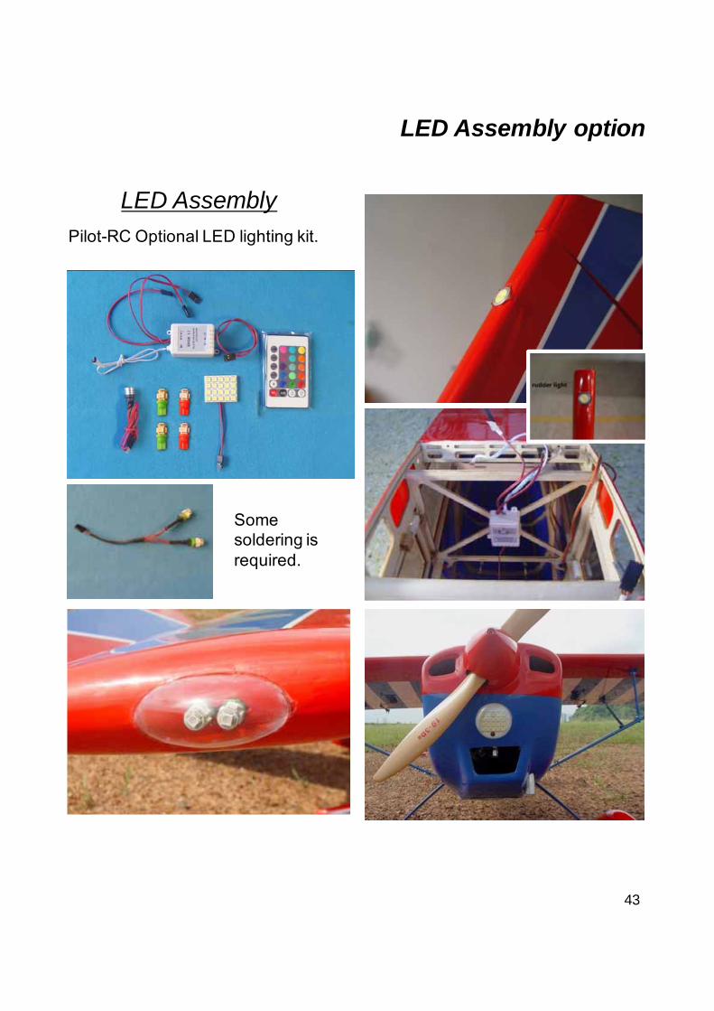
LED Assembly option
LED Assembly
Pilot-RC Optional LED lighting kit.
Some soldering is required.


![KAMOME K-7 RUDDER - kamome- · PDF fileleft drawing. ] 4. ... [Neck bearing] 主舵 [Main rudder ... [Link mechanism] ラダーキャリア [Rudder carrier](https://img.pdfslide.net/doc/110x75/5aa194617f8b9ac67a8bf8f2/kamome-k-7-rudder-kamome-drawing-4-neck-bearing-main-rudder.jpg)