Embed Size (px)
Citation preview

NORDSON CORPORATION � DAWSONVILLE, GEORGIA � USA
www.nordson.com
ATS Melters
Customer Product ManualPart 331149G
Issued 11/05

� 2005 Nordson CorporationAll rights reserved
Part 331149G
Nordson Corporation welcomes requests for information, comments and inquiries about its products.General information about Nordson can be found on the Internet using the following address:
http://www.nordson.com.
Address all correspondence to:
Nordson CorporationAttn: Nonwovens Marketing Department
12 Nordson DriveDawsonville, GA 30534
Notice
This is a Nordson Corporation publication which is protected by copyright. Original copyright date 1999. No part of this document may be photocopied, reproduced, or translated to another language without the prior written consent of
Nordson Corporation. The information contained in this publication is subject to change without notice.
Trademarks
AccuJet, AeroCharge, Apogee, AquaGuard, Asymtek, Automove, Baitgun, Blue Box, CanWorks, Century, CF, Clean Coat, CleanSleeve, CleanSpray,ColorMax, Control Coat, Coolwave, Cross-Cut, Cyclo-Kinetic, Dispensejet, DispenseMate, DuraBlue, Durafiber, Dura-Screen, Durasystem, Easy Coat,Easymove Plus, Ecodry, Econo-Coat, e.dot, EFD, e stylized, ETI, Excel 2000, Fillmaster, FlexiCoat, Flexi-Spray, Flex-O-Coat, Flow Sentry, Fluidmove,
FoamMelt, FoamMix, Heli-flow, Helix, Horizon, Hot Shot, iControl, iFlow, Isocoil, Isocore, Iso-Flo, iTRAX, Kinetix, Little Squirt, Magnastatic, March, MEG,Meltex, Microcoat, Micromark, MicroSet, Millennium, Mini Squirt, Mountaingate, MultiScan, Nordson, OptiMix, Package of Values, Pattern View, PermaFlo,Plasmod, Porous Coat, PowderGrid, Powderware, Printplus, Prism, ProBlue, Pro-Flo, ProLink, Pro-Meter, Pro-Stream, RBX, Rhino, Saturn, Scoreguard,Seal Sentry, Select Charge, Select Coat, Select Cure, Slautterback, Smart-Coat, Solder Plus, Spectrum, Speed-Coat, SureBead, Sure Clean, Sure Coat,
Sure-Max, Tracking Plus, Trends, Tribomatic, Ultrasaver, UpTime, Vantage, Veritec, VersaBlue, Versa-Coat, Versa-Screen, Versa-Spray, Walcom,Watermark, and When you expect more. are registered trademarks of Nordson Corporation.
Accubar, Advanced Plasma Systems, AeroDeck, AeroWash, AltaBlueAquaCure, ATS, Auto-Flo, AutoScan, Blue Series, Check Mate, Classicblue,Controlled Fiberization, Control Weave, CPX, DispensLink, Dry Cure, DuraBraid, DuraCoat, DuraDrum, DuraPail, Easy Clean, EasyOn, Eclipse, E-Nordson,
Equi=Bead, ESP, Fill Sentry, G−Net, G−Site, HDLV, iON, Iso-Flex, iTrend, Lacquer Cure, Lean Cell, LogiComm, Maverick, Maxima, MicroFin, MicroMax,MiniBlue, Minimeter, Multifil, Myritex, OptiStroke, PatternPro, PCI, Powder Pilot, Powercure, Primarc, Process Sentry, Prodigy, Pulse Spray, Quad Cure,Ready Coat, Royal Blue, Select Series, Sensomatic, Shaftshield, SheetAire, Smart, SolidBlue, Spectral, Spectronic, SpeedKing, Spray Works, Summit,
Sure Brand, SureSeal, Sure Wrap, Swirl Coat, Tempus, ThruWave, Trade Plus, Trak, TrueBlue, Ultra, Ultrasmart, Universal, Vista, Web Cure, and2 Rings (Design) are trademarks of Nordson Corporation.
Designations and trademarks stated in this document may be brands that, when used by third parties for their own purposes, could lead to violation of the owners’ rights.
Loctite is a registered trademark of Loctite Corporation.Never Seez is a registered trademark of Bostik Inc.
Parker Lubricant is a registered trademark of Parker Seal. Viton is a registered trademark of DuPont Dow Elastomers. L.L.C.
Table of Contents i
Part 331149G� 2005 Nordson Corporation
Table of Contents
Safety 1-1. . . . . . . . . . . . . . . . . . . . . . . . . . . . . . . . . . . . . . . . . . . . . . . . . . . . . Safety Alert Symbols 1-1. . . . . . . . . . . . . . . . . . . . . . . . . . . . . . . . . . . . . . . . Responsibilities of the Equipment Owner 1-2. . . . . . . . . . . . . . . . . . . . . .
Safety Information 1-2. . . . . . . . . . . . . . . . . . . . . . . . . . . . . . . . . . . . . . . Instructions, Requirements, and Standards 1-2. . . . . . . . . . . . . . . . . . User Qualifications 1-3. . . . . . . . . . . . . . . . . . . . . . . . . . . . . . . . . . . . . . .
Applicable Industry Safety Practices 1-3. . . . . . . . . . . . . . . . . . . . . . . . . . Intended Use of the Equipment 1-3. . . . . . . . . . . . . . . . . . . . . . . . . . . . Instructions and Safety Messages 1-3. . . . . . . . . . . . . . . . . . . . . . . . . . Installation Practices 1-4. . . . . . . . . . . . . . . . . . . . . . . . . . . . . . . . . . . . . Operating Practices 1-4. . . . . . . . . . . . . . . . . . . . . . . . . . . . . . . . . . . . . . Maintenance and Repair Practices 1-5. . . . . . . . . . . . . . . . . . . . . . . . .
Equipment Safety Information 1-5. . . . . . . . . . . . . . . . . . . . . . . . . . . . . . . . Equipment Shutdown 1-6. . . . . . . . . . . . . . . . . . . . . . . . . . . . . . . . . . . . .
Relieving System Hydraulic Pressure 1-6. . . . . . . . . . . . . . . . . . . . . De-energizing the System 1-6. . . . . . . . . . . . . . . . . . . . . . . . . . . . . . Disabling the Guns 1-6. . . . . . . . . . . . . . . . . . . . . . . . . . . . . . . . . . . .
General Safety Warnings and Cautions 1-7. . . . . . . . . . . . . . . . . . . . . . Other Safety Precautions 1-10. . . . . . . . . . . . . . . . . . . . . . . . . . . . . . . . . First Aid 1-10. . . . . . . . . . . . . . . . . . . . . . . . . . . . . . . . . . . . . . . . . . . . . . . .
Safety Labels and Tags 1-11. . . . . . . . . . . . . . . . . . . . . . . . . . . . . . . . . . . . .
Description 2-1. . . . . . . . . . . . . . . . . . . . . . . . . . . . . . . . . . . . . . . . . . . . . . . . Introduction 2-1. . . . . . . . . . . . . . . . . . . . . . . . . . . . . . . . . . . . . . . . . . . . . . . . Product Description 2-2. . . . . . . . . . . . . . . . . . . . . . . . . . . . . . . . . . . . . . . . .
Intended Use 2-2. . . . . . . . . . . . . . . . . . . . . . . . . . . . . . . . . . . . . . . . . . . . Limitations of Use 2-2. . . . . . . . . . . . . . . . . . . . . . . . . . . . . . . . . . . . . . . .
Hot Melt System Overview 2-3. . . . . . . . . . . . . . . . . . . . . . . . . . . . . . . . . . Melter 2-4. . . . . . . . . . . . . . . . . . . . . . . . . . . . . . . . . . . . . . . . . . . . . . . . . . Hoses 2-4. . . . . . . . . . . . . . . . . . . . . . . . . . . . . . . . . . . . . . . . . . . . . . . . . . Applicators 2-4. . . . . . . . . . . . . . . . . . . . . . . . . . . . . . . . . . . . . . . . . . . . . . Metering Stations 2-5. . . . . . . . . . . . . . . . . . . . . . . . . . . . . . . . . . . . . . . . Drum Unloaders 2-5. . . . . . . . . . . . . . . . . . . . . . . . . . . . . . . . . . . . . . . . . ACMs 2-5. . . . . . . . . . . . . . . . . . . . . . . . . . . . . . . . . . . . . . . . . . . . . . . . . .
Melter Overview 2-6. . . . . . . . . . . . . . . . . . . . . . . . . . . . . . . . . . . . . . . . . . . . Control System 2-9. . . . . . . . . . . . . . . . . . . . . . . . . . . . . . . . . . . . . . . . . . Hydraulic System 2-10. . . . . . . . . . . . . . . . . . . . . . . . . . . . . . . . . . . . . . . . Drive System 2-10. . . . . . . . . . . . . . . . . . . . . . . . . . . . . . . . . . . . . . . . . . . .
Table of Contentsii
Part 331149G � 2005 Nordson Corporation
Installation 3-1. . . . . . . . . . . . . . . . . . . . . . . . . . . . . . . . . . . . . . . . . . . . . . . . Introduction 3-1. . . . . . . . . . . . . . . . . . . . . . . . . . . . . . . . . . . . . . . . . . . . . . . . Preliminary Tasks 3-2. . . . . . . . . . . . . . . . . . . . . . . . . . . . . . . . . . . . . . . . . .
Check the Parts Inventory 3-2. . . . . . . . . . . . . . . . . . . . . . . . . . . . . . . . . Select the Applicator Locations 3-3. . . . . . . . . . . . . . . . . . . . . . . . . . . . Select the Melter Location 3-3. . . . . . . . . . . . . . . . . . . . . . . . . . . . . . . . .
Mechanical Installation 3-6. . . . . . . . . . . . . . . . . . . . . . . . . . . . . . . . . . . . . . Install the Applicators and the Melter 3-6. . . . . . . . . . . . . . . . . . . . . . . Install a Line-Speed Generator 3-6. . . . . . . . . . . . . . . . . . . . . . . . . . . . . Install Hoses 3-7. . . . . . . . . . . . . . . . . . . . . . . . . . . . . . . . . . . . . . . . . . . . Connect Air to the Melter 3-11. . . . . . . . . . . . . . . . . . . . . . . . . . . . . . . . . . Connect Air to the Applicators 3-11. . . . . . . . . . . . . . . . . . . . . . . . . . . . . Change the Circulation in a Manifold 3-12. . . . . . . . . . . . . . . . . . . . . . . . Connect a Bulk Fill System to the Melter 3-13. . . . . . . . . . . . . . . . . . . .
Electrical Installation 3-13. . . . . . . . . . . . . . . . . . . . . . . . . . . . . . . . . . . . . . . . Prevent Electrical Noise 3-13. . . . . . . . . . . . . . . . . . . . . . . . . . . . . . . . . . Connect Hose and Applicator Cordsets 3-14. . . . . . . . . . . . . . . . . . . . . Connect the Wiring for Applicator Solenoid Valves 3-19. . . . . . . . . . . . Connect I/O Devices 3-19. . . . . . . . . . . . . . . . . . . . . . . . . . . . . . . . . . . . . Install a Network Cable 3-20. . . . . . . . . . . . . . . . . . . . . . . . . . . . . . . . . . . Connect Power 3-21. . . . . . . . . . . . . . . . . . . . . . . . . . . . . . . . . . . . . . . . . .
Record of System Configuration 3-22. . . . . . . . . . . . . . . . . . . . . . . . . . . . . .
Setup 4-1. . . . . . . . . . . . . . . . . . . . . . . . . . . . . . . . . . . . . . . . . . . . . . . . . . . . . Introduction 4-1. . . . . . . . . . . . . . . . . . . . . . . . . . . . . . . . . . . . . . . . . . . . . . . . About Pre-2000 PanelMate and PanelView Software 4-2. . . . . . . . . . . . System Navigation and Interface 4-4. . . . . . . . . . . . . . . . . . . . . . . . . . . . .
Displaying Screens 4-4. . . . . . . . . . . . . . . . . . . . . . . . . . . . . . . . . . . . . . . Entering the Password 4-6. . . . . . . . . . . . . . . . . . . . . . . . . . . . . . . . . . . . Determining Zone Names and Numbers 4-7. . . . . . . . . . . . . . . . . . . . Entering Values 4-10. . . . . . . . . . . . . . . . . . . . . . . . . . . . . . . . . . . . . . . . . .
System Setup 4-13. . . . . . . . . . . . . . . . . . . . . . . . . . . . . . . . . . . . . . . . . . . . . . Selecting Units of Measurement 4-13. . . . . . . . . . . . . . . . . . . . . . . . . . . Setting the PLC Clock 4-14. . . . . . . . . . . . . . . . . . . . . . . . . . . . . . . . . . . . Enabling or Disabling Temperature Zones 4-16. . . . . . . . . . . . . . . . . . . Setting Zone Temperatures 4-18. . . . . . . . . . . . . . . . . . . . . . . . . . . . . . . . Entering a Temperature Offset 4-20. . . . . . . . . . . . . . . . . . . . . . . . . . . . . Setting Up Sequential Startup 4-22. . . . . . . . . . . . . . . . . . . . . . . . . . . . . Setting Up Startup Delay 4-25. . . . . . . . . . . . . . . . . . . . . . . . . . . . . . . . . . Setting Temperature Alarms 4-27. . . . . . . . . . . . . . . . . . . . . . . . . . . . . . . Setting the Shutdown Temperature 4-31. . . . . . . . . . . . . . . . . . . . . . . . . Setting Up Temperature Setback 4-32. . . . . . . . . . . . . . . . . . . . . . . . . . . Setting PID Values 4-37. . . . . . . . . . . . . . . . . . . . . . . . . . . . . . . . . . . . . . . Setting Up Pumps for Key-to-Line Control 4-40. . . . . . . . . . . . . . . . . . . Setting the Pump Pressure 4-45. . . . . . . . . . . . . . . . . . . . . . . . . . . . . . . . Setting the Applicator Air Ramps 4-47. . . . . . . . . . . . . . . . . . . . . . . . . . . Setting Pressure Alarms 4-52. . . . . . . . . . . . . . . . . . . . . . . . . . . . . . . . . . Saving Settings 4-58. . . . . . . . . . . . . . . . . . . . . . . . . . . . . . . . . . . . . . . . . . Resetting Parameters to Factory Values 4-60. . . . . . . . . . . . . . . . . . . . Recording Your Settings 4-61. . . . . . . . . . . . . . . . . . . . . . . . . . . . . . . . . .
System Flushing 4-62. . . . . . . . . . . . . . . . . . . . . . . . . . . . . . . . . . . . . . . . . . .
Table of Contents iii
Part 331149G� 2005 Nordson Corporation
Setup (contd)Control Valve Adjustment 4-62. . . . . . . . . . . . . . . . . . . . . . . . . . . . . . . . . . . .
Adjusting Recirculation Pressure: Pressure-Fed Applicator/PCV 4-64Adjusting Recirculation Pressure: Pressure-FedApplicator/AOPCV 4-66. . . . . . . . . . . . . . . . . . . . . . . . . . . . . . . . . . . . . . . Adjusting Recirculation Pressure: Pressure-Fed Applicator/FCV 4-69Adjusting Recirculation Pressure: Single-Pump MeteringApplicator in a Continuous Application 4-71. . . . . . . . . . . . . . . . . . . . . . Adjusting Recirculation Pressure: Single-Pump MeteringApplicator in an Intermittent Application 4-73. . . . . . . . . . . . . . . . . . . . . Adjusting Recirculation Pressure: Multi-Pump Metering Applicator 4-76Adjusting Recirculation Pressure: Universal Slice Applicator 4-78. . .
Records of Settings 4-80. . . . . . . . . . . . . . . . . . . . . . . . . . . . . . . . . . . . . . . . .
Operation 5-1. . . . . . . . . . . . . . . . . . . . . . . . . . . . . . . . . . . . . . . . . . . . . . . . . Introduction 5-1. . . . . . . . . . . . . . . . . . . . . . . . . . . . . . . . . . . . . . . . . . . . . . . . Starting the System 5-2. . . . . . . . . . . . . . . . . . . . . . . . . . . . . . . . . . . . . . . . . Loading Settings 5-6. . . . . . . . . . . . . . . . . . . . . . . . . . . . . . . . . . . . . . . . . . . Monitoring System Activity 5-8. . . . . . . . . . . . . . . . . . . . . . . . . . . . . . . . . . . Operating a Pump in the Manual Mode 5-13. . . . . . . . . . . . . . . . . . . . . . . . Adjusting Pump Output in the Automatic Mode 5-17. . . . . . . . . . . . . . . . . Entering and Exiting the Setback Mode 5-19. . . . . . . . . . . . . . . . . . . . . . . . Acknowledging Alarms 5-23. . . . . . . . . . . . . . . . . . . . . . . . . . . . . . . . . . . . . . Setting Up Automatic Startup 5-25. . . . . . . . . . . . . . . . . . . . . . . . . . . . . . . . Shutting Down the System 5-27. . . . . . . . . . . . . . . . . . . . . . . . . . . . . . . . . .
Maintenance 6-1. . . . . . . . . . . . . . . . . . . . . . . . . . . . . . . . . . . . . . . . . . . . . . Introduction 6-1. . . . . . . . . . . . . . . . . . . . . . . . . . . . . . . . . . . . . . . . . . . . . . . . Required Tools and Supplies 6-1. . . . . . . . . . . . . . . . . . . . . . . . . . . . . . . . . Recommended Maintenance Schedule 6-2. . . . . . . . . . . . . . . . . . . . . . . . Preparation for Maintenance Activities 6-3. . . . . . . . . . . . . . . . . . . . . . . .
Removing Power 6-4. . . . . . . . . . . . . . . . . . . . . . . . . . . . . . . . . . . . . . . . Relieving System Pressure 6-5. . . . . . . . . . . . . . . . . . . . . . . . . . . . . . . .
Remove Power to the Motors 6-5. . . . . . . . . . . . . . . . . . . . . . . . . . . Relieve Pressure at the Melter Manifolds 6-5. . . . . . . . . . . . . . . . . Relieve Pressure at the Applicators 6-6. . . . . . . . . . . . . . . . . . . . . .
Removing a Panel 6-7. . . . . . . . . . . . . . . . . . . . . . . . . . . . . . . . . . . . . . . Closing a Pre-Pump Filter Valve 6-7. . . . . . . . . . . . . . . . . . . . . . . . . . . Draining the System 6-8. . . . . . . . . . . . . . . . . . . . . . . . . . . . . . . . . . . . . .
Pump-Drain Method 6-8. . . . . . . . . . . . . . . . . . . . . . . . . . . . . . . . . . . Manifold-Drain Method 6-9. . . . . . . . . . . . . . . . . . . . . . . . . . . . . . . . . Reservoir-Drain Method 6-10. . . . . . . . . . . . . . . . . . . . . . . . . . . . . . . .
Maintenance Procedures 6-11. . . . . . . . . . . . . . . . . . . . . . . . . . . . . . . . . . . . Cleaning or Replacing a Manifold Filter Screen 6-11. . . . . . . . . . . . . . .
Remove the Manifold Filter 6-12. . . . . . . . . . . . . . . . . . . . . . . . . . . . . Clean the Manifold Filter Screen 6-12. . . . . . . . . . . . . . . . . . . . . . . . . Install the Manifold Filter 6-13. . . . . . . . . . . . . . . . . . . . . . . . . . . . . . . .
Replacing the Manifold Filter Bushing O-Rings 6-14. . . . . . . . . . . . . . . Checking a Pressure Relief Valve 6-16. . . . . . . . . . . . . . . . . . . . . . . . . . Cleaning Inside the Electrical Cabinet 6-17. . . . . . . . . . . . . . . . . . . . . . . Checking the Torque on a Pump Bolt 6-17. . . . . . . . . . . . . . . . . . . . . . .
Table of Contentsiv
Part 331149G � 2005 Nordson Corporation
Maintenance (contd)Cleaning or Replacing a Pre-Pump Filter Valve 6-18. . . . . . . . . . . . . . .
Remove the Pre-Pump Filter Valve 6-18. . . . . . . . . . . . . . . . . . . . . . . Clean the Pre-Pump Filter Valve Screen 6-18. . . . . . . . . . . . . . . . . . Install the Pre-Pump Filter Valve 6-19. . . . . . . . . . . . . . . . . . . . . . . . .
Changing the Oil in a Reducer 6-20. . . . . . . . . . . . . . . . . . . . . . . . . . . . . Cleaning (Flushing) the System 6-21. . . . . . . . . . . . . . . . . . . . . . . . . . . .
Flush the Melter and Supply Hoses 6-21. . . . . . . . . . . . . . . . . . . . . . Flush the Applicators and Any Return Hoses 6-22. . . . . . . . . . . . . . Restore the System to Normal Operation 6-23. . . . . . . . . . . . . . . . .
Cleaning Parts 6-24. . . . . . . . . . . . . . . . . . . . . . . . . . . . . . . . . . . . . . . . . . .
Temperature Control System 7-1. . . . . . . . . . . . . . . . . . . . . . . . . . . . . . . Introduction 7-1. . . . . . . . . . . . . . . . . . . . . . . . . . . . . . . . . . . . . . . . . . . . . . . . Temperature Control System Overview 7-2. . . . . . . . . . . . . . . . . . . . . . . . Troubleshooting Tables 7-3. . . . . . . . . . . . . . . . . . . . . . . . . . . . . . . . . . . . . .
Alarm Messages 7-3. . . . . . . . . . . . . . . . . . . . . . . . . . . . . . . . . . . . . . . . . Component Heating Problems 7-7. . . . . . . . . . . . . . . . . . . . . . . . . . . . .
Repair Procedures 7-16. . . . . . . . . . . . . . . . . . . . . . . . . . . . . . . . . . . . . . . . . Replacing a Hopper Heater Strip 7-17. . . . . . . . . . . . . . . . . . . . . . . . . . . Replacing an RTD or Thermoswitch 7-18. . . . . . . . . . . . . . . . . . . . . . . . Replacing a Manifold Heater Plate 7-20. . . . . . . . . . . . . . . . . . . . . . . . .
Hydraulic System 8-1. . . . . . . . . . . . . . . . . . . . . . . . . . . . . . . . . . . . . . . . . . Introduction 8-1. . . . . . . . . . . . . . . . . . . . . . . . . . . . . . . . . . . . . . . . . . . . . . . . Hydraulic System Overview 8-2. . . . . . . . . . . . . . . . . . . . . . . . . . . . . . . . . .
Major Components and Hydraulic Schematics 8-2. . . . . . . . . . . . . . . Run Mode, Pressure-Fed Applicator 8-4. . . . . . . . . . . . . . . . . . . . . . Run Mode, Metering Applicator 8-5. . . . . . . . . . . . . . . . . . . . . . . . . . Recirculation Mode, Metering Applicator 8-6. . . . . . . . . . . . . . . . . . Drain Mode 8-7. . . . . . . . . . . . . . . . . . . . . . . . . . . . . . . . . . . . . . . . . . .
Pre-Pump Filter Valve 8-8. . . . . . . . . . . . . . . . . . . . . . . . . . . . . . . . . . . . Manifold 8-8. . . . . . . . . . . . . . . . . . . . . . . . . . . . . . . . . . . . . . . . . . . . . . . .
Manifold Positions and Streams 8-8. . . . . . . . . . . . . . . . . . . . . . . . . Manifold Components 8-9. . . . . . . . . . . . . . . . . . . . . . . . . . . . . . . . . . Manifold Circulation 8-11. . . . . . . . . . . . . . . . . . . . . . . . . . . . . . . . . . . .
Hoses 8-11. . . . . . . . . . . . . . . . . . . . . . . . . . . . . . . . . . . . . . . . . . . . . . . . . . Troubleshooting Tables 8-12. . . . . . . . . . . . . . . . . . . . . . . . . . . . . . . . . . . . . .
Leakage Problems 8-12. . . . . . . . . . . . . . . . . . . . . . . . . . . . . . . . . . . . . . . Adhesive Output Problems 8-13. . . . . . . . . . . . . . . . . . . . . . . . . . . . . . . .
Repair Procedures 8-15. . . . . . . . . . . . . . . . . . . . . . . . . . . . . . . . . . . . . . . . . Replacing a Pump 8-16. . . . . . . . . . . . . . . . . . . . . . . . . . . . . . . . . . . . . . .
Prepare to Remove the Pump 8-16. . . . . . . . . . . . . . . . . . . . . . . . . . . Remove the Drive and Pump Assembly 8-18. . . . . . . . . . . . . . . . . . . Remove and Inspect the Pump 8-20. . . . . . . . . . . . . . . . . . . . . . . . . . Install the Drive and Pump Assembly 8-22. . . . . . . . . . . . . . . . . . . . .
Replacing a Valve 8-23. . . . . . . . . . . . . . . . . . . . . . . . . . . . . . . . . . . . . . . . Remove the Valve 8-24. . . . . . . . . . . . . . . . . . . . . . . . . . . . . . . . . . . . . Install the Valve 8-25. . . . . . . . . . . . . . . . . . . . . . . . . . . . . . . . . . . . . . .
Cleaning or Replacing a Hopper/Grid/Reservoir Assembly 8-26. . . . . Remove the Assembly 8-26. . . . . . . . . . . . . . . . . . . . . . . . . . . . . . . . . Install the Assembly 8-28. . . . . . . . . . . . . . . . . . . . . . . . . . . . . . . . . . . .
Table of Contents v
Part 331149G� 2005 Nordson Corporation
Hydraulic System (contd)Removing and Installing a Manifold 8-28. . . . . . . . . . . . . . . . . . . . . . . . .
Remove the Manifold 8-28. . . . . . . . . . . . . . . . . . . . . . . . . . . . . . . . . . Install the Manifold 8-30. . . . . . . . . . . . . . . . . . . . . . . . . . . . . . . . . . . . .
Upgrading/Downgrading a Manifold Position 8-32. . . . . . . . . . . . . . . . . Add a Manifold to a Blank Manifold Position 8-32. . . . . . . . . . . . . . . Remove a Manifold from a Position 8-34. . . . . . . . . . . . . . . . . . . . . . Change a Manifold from Single to Dual or Dual to Single 8-35. . . .
Drive System 9-1. . . . . . . . . . . . . . . . . . . . . . . . . . . . . . . . . . . . . . . . . . . . . . Introduction 9-1. . . . . . . . . . . . . . . . . . . . . . . . . . . . . . . . . . . . . . . . . . . . . . . . Drive System Overview 9-2. . . . . . . . . . . . . . . . . . . . . . . . . . . . . . . . . . . . . Troubleshooting Tables 9-3. . . . . . . . . . . . . . . . . . . . . . . . . . . . . . . . . . . . . .
Alarm Messages 9-4. . . . . . . . . . . . . . . . . . . . . . . . . . . . . . . . . . . . . . . . . Drive System Problems 9-5. . . . . . . . . . . . . . . . . . . . . . . . . . . . . . . . . . .
Drive Assembly Component Replacement 9-6. . . . . . . . . . . . . . . . . . . . . Removing a Drive Assembly 9-6. . . . . . . . . . . . . . . . . . . . . . . . . . . . . . . Replacing a Drive Assembly Component 9-8. . . . . . . . . . . . . . . . . . . . Installing a Drive Assembly 9-10. . . . . . . . . . . . . . . . . . . . . . . . . . . . . . . .
Pressure Monitoring 10-1. . . . . . . . . . . . . . . . . . . . . . . . . . . . . . . . . . . . . . . Introduction 10-1. . . . . . . . . . . . . . . . . . . . . . . . . . . . . . . . . . . . . . . . . . . . . . . . Pressure Monitoring Overview 10-2. . . . . . . . . . . . . . . . . . . . . . . . . . . . . . .
Location of Pressure Transducers 10-3. . . . . . . . . . . . . . . . . . . . . . . . . . Pressure Transducer Specifications 10-4. . . . . . . . . . . . . . . . . . . . . . . .
Troubleshooting Tables 10-4. . . . . . . . . . . . . . . . . . . . . . . . . . . . . . . . . . . . . . Alarm Messages 10-5. . . . . . . . . . . . . . . . . . . . . . . . . . . . . . . . . . . . . . . . . Pressure Problems 10-6. . . . . . . . . . . . . . . . . . . . . . . . . . . . . . . . . . . . . . .
Pressure Transducer Check 10-8. . . . . . . . . . . . . . . . . . . . . . . . . . . . . . . . . Pressure Transducer Replacement 10-10. . . . . . . . . . . . . . . . . . . . . . . . . . .
Removing a Pressure Transducer 10-10. . . . . . . . . . . . . . . . . . . . . . . . . . Installing a Pressure Transducer 10-12. . . . . . . . . . . . . . . . . . . . . . . . . . .
Level Control Option 11-1. . . . . . . . . . . . . . . . . . . . . . . . . . . . . . . . . . . . . . . Introduction 11-1. . . . . . . . . . . . . . . . . . . . . . . . . . . . . . . . . . . . . . . . . . . . . . . . Level Control Option Overview 11-2. . . . . . . . . . . . . . . . . . . . . . . . . . . . . . . Troubleshooting Tables 11-4. . . . . . . . . . . . . . . . . . . . . . . . . . . . . . . . . . . . . .
Alarm Messages 11-5. . . . . . . . . . . . . . . . . . . . . . . . . . . . . . . . . . . . . . . . . Level Control Problems 11-6. . . . . . . . . . . . . . . . . . . . . . . . . . . . . . . . . . .
Troubleshooting Procedures 11-8. . . . . . . . . . . . . . . . . . . . . . . . . . . . . . . . . Checking a Level Control Probe 11-8. . . . . . . . . . . . . . . . . . . . . . . . . . . . Checking a Level Control Probe Cable 11-10. . . . . . . . . . . . . . . . . . . . . .
Maintenance and Repair Procedures 11-12. . . . . . . . . . . . . . . . . . . . . . . . . . Calibrating a Level Control Transmitter 11-12. . . . . . . . . . . . . . . . . . . . . . Recording Level Control Transmitter Calibration Data 11-14. . . . . . . . . Recalibrating a Level Control Transmitter 11-16. . . . . . . . . . . . . . . . . . . . Replacing a Level Control Probe 11-17. . . . . . . . . . . . . . . . . . . . . . . . . . .
Remove the Level Control Probe 11-17. . . . . . . . . . . . . . . . . . . . . . . . Install the Level Control Probe 11-18. . . . . . . . . . . . . . . . . . . . . . . . . . .
Replacing a Level Control Probe Cable 11-19. . . . . . . . . . . . . . . . . . . . . Cleaning or Replacing a Bulk Fill Valve Filter Screen 11-21. . . . . . . . . .
Remove the Filter 11-21. . . . . . . . . . . . . . . . . . . . . . . . . . . . . . . . . . . . . . Clean the Filter Screen 11-22. . . . . . . . . . . . . . . . . . . . . . . . . . . . . . . . . Install the Filter 11-22. . . . . . . . . . . . . . . . . . . . . . . . . . . . . . . . . . . . . . . .
Replacing an H20 Module 11-23. . . . . . . . . . . . . . . . . . . . . . . . . . . . . . . . .
Table of Contentsvi
Part 331149G � 2005 Nordson Corporation
Parts 12-1. . . . . . . . . . . . . . . . . . . . . . . . . . . . . . . . . . . . . . . . . . . . . . . . . . . . . . Using the Illustrated Parts Lists 12-1. . . . . . . . . . . . . . . . . . . . . . . . . . . . . . Hopper Assembly Parts Lists 12-3. . . . . . . . . . . . . . . . . . . . . . . . . . . . . . . .
25-kg Single Melter Hopper Parts 12-4. . . . . . . . . . . . . . . . . . . . . . . . . . 50-kg Single Melter Hopper Parts 12-6. . . . . . . . . . . . . . . . . . . . . . . . . . 100-kg Single Melter Hopper Parts 12-8. . . . . . . . . . . . . . . . . . . . . . . . . 50-kg Dual Melter Hopper Parts 12-10. . . . . . . . . . . . . . . . . . . . . . . . . . . . 100-kg Dual Melter Hopper Parts 12-12. . . . . . . . . . . . . . . . . . . . . . . . . . . 200-kg Dual Melter Hopper Parts 12-14. . . . . . . . . . . . . . . . . . . . . . . . . . . 25-kg Twin Melter Hopper Parts 12-16. . . . . . . . . . . . . . . . . . . . . . . . . . . . 50-kg Twin Melter Hopper Parts 12-18. . . . . . . . . . . . . . . . . . . . . . . . . . . . 100-kg Twin Melter Hopper Parts 12-20. . . . . . . . . . . . . . . . . . . . . . . . . .
Common Assembly Parts Lists 12-22. . . . . . . . . . . . . . . . . . . . . . . . . . . . . . . Pre-Pump Filter Valve Parts List 12-24. . . . . . . . . . . . . . . . . . . . . . . . . . . . . . Cover/Lid and Level Control Parts Lists 12-27. . . . . . . . . . . . . . . . . . . . . . .
Single Melter (Without Level Control) Cover/Lid Parts 12-28. . . . . . . . . One-Lid Dual Melter (Without Level Control) Cover/Lid Parts 12-30. . . Two-Lid Dual Melter or Twin Melter (Without Level Control)Cover/Lid Parts 12-32. . . . . . . . . . . . . . . . . . . . . . . . . . . . . . . . . . . . . . . . . . Single Melter (With Level Control) Cover/Lid Parts 12-34. . . . . . . . . . . . One-Lid Dual Melter (With Level Control) Cover/Lid Parts 12-36. . . . . Two-Lid Dual Melter (With Level Control) Cover/Lid Parts 12-38. . . . . Twin Melter (With Level Control) Cover/Lid Parts 12-40. . . . . . . . . . . . . H20-2 Bulk Fill Valve Parts 12-42. . . . . . . . . . . . . . . . . . . . . . . . . . . . . . . . H20 Module Parts 12-44. . . . . . . . . . . . . . . . . . . . . . . . . . . . . . . . . . . . . . . . H20-2 Bulk Fill Valve Filter Parts 12-46. . . . . . . . . . . . . . . . . . . . . . . . . . .
Manifold and Control Valve Parts Lists 12-47. . . . . . . . . . . . . . . . . . . . . . . . Manifold and Control Valve Interface Parts 12-48. . . . . . . . . . . . . . . . . . Blank Manifold Parts 12-50. . . . . . . . . . . . . . . . . . . . . . . . . . . . . . . . . . . . . Single-Stream Manifold Parts 12-51. . . . . . . . . . . . . . . . . . . . . . . . . . . . . . Dual-Stream Manifold Parts 12-55. . . . . . . . . . . . . . . . . . . . . . . . . . . . . . . Manifold Filter Parts 12-58. . . . . . . . . . . . . . . . . . . . . . . . . . . . . . . . . . . . . . Pressure Relief Valve Parts 12-60. . . . . . . . . . . . . . . . . . . . . . . . . . . . . . . Pressure Transducer Parts 12-62. . . . . . . . . . . . . . . . . . . . . . . . . . . . . . . . Pressure Control Valve Parts 12-64. . . . . . . . . . . . . . . . . . . . . . . . . . . . . . Flow Control Valve Parts 12-66. . . . . . . . . . . . . . . . . . . . . . . . . . . . . . . . . . Air-Operated Pressure Control Valve Parts 12-68. . . . . . . . . . . . . . . . . . Pneumatic Assembly Parts 12-70. . . . . . . . . . . . . . . . . . . . . . . . . . . . . . . .
Drive and Pump Parts Lists 12-73. . . . . . . . . . . . . . . . . . . . . . . . . . . . . . . . . . Drive and Pump Interface Parts 12-74. . . . . . . . . . . . . . . . . . . . . . . . . . . . Drive Parts 12-76. . . . . . . . . . . . . . . . . . . . . . . . . . . . . . . . . . . . . . . . . . . . . . Single-Stream Pump Parts 12-78. . . . . . . . . . . . . . . . . . . . . . . . . . . . . . . . Dual-Stream Pump Parts 12-80. . . . . . . . . . . . . . . . . . . . . . . . . . . . . . . . .
Electrical System Parts Lists 12-82. . . . . . . . . . . . . . . . . . . . . . . . . . . . . . . . . 240 VAC Electrical Parts 12-82. . . . . . . . . . . . . . . . . . . . . . . . . . . . . . . . . . 400 VAC Electrical Parts 12-82. . . . . . . . . . . . . . . . . . . . . . . . . . . . . . . . . . XL3 Option Parts 12-82. . . . . . . . . . . . . . . . . . . . . . . . . . . . . . . . . . . . . . . .
Table of Contents vii
Part 331149G� 2005 Nordson Corporation
Parts (contd)Hoses and Hose Fittings 12-83. . . . . . . . . . . . . . . . . . . . . . . . . . . . . . . . . . . .
M-Style Hoses (8 mm) 12-83. . . . . . . . . . . . . . . . . . . . . . . . . . . . . . . . . . . . M-Style Hoses (13 mm) 12-84. . . . . . . . . . . . . . . . . . . . . . . . . . . . . . . . . . . Hose-to-Melter Fittings 12-85. . . . . . . . . . . . . . . . . . . . . . . . . . . . . . . . . . . Hose-to-Applicator Fittings 12-86. . . . . . . . . . . . . . . . . . . . . . . . . . . . . . . . Swivel Fittings 12-87. . . . . . . . . . . . . . . . . . . . . . . . . . . . . . . . . . . . . . . . . . . Adapter Fittings 12-87. . . . . . . . . . . . . . . . . . . . . . . . . . . . . . . . . . . . . . . . . .
Adapter, Splitter, and Extension Cables 12-88. . . . . . . . . . . . . . . . . . . . . . . M-Style Adapter and Splitter Cables 12-88. . . . . . . . . . . . . . . . . . . . . . . . M-Style Extension Cables 12-89. . . . . . . . . . . . . . . . . . . . . . . . . . . . . . . . .
Optional Accessories 12-92. . . . . . . . . . . . . . . . . . . . . . . . . . . . . . . . . . . . . . . Caster Kit 12-92. . . . . . . . . . . . . . . . . . . . . . . . . . . . . . . . . . . . . . . . . . . . . . . Hydraulic Pressure Gauges 12-92. . . . . . . . . . . . . . . . . . . . . . . . . . . . . . .
Recommended Spare Parts and Supplies 12-94. . . . . . . . . . . . . . . . . . . . .
Technical Data 13-1. . . . . . . . . . . . . . . . . . . . . . . . . . . . . . . . . . . . . . . . . . . . . Specifications 13-1. . . . . . . . . . . . . . . . . . . . . . . . . . . . . . . . . . . . . . . . . . . . . .
Melter Specifications 13-1. . . . . . . . . . . . . . . . . . . . . . . . . . . . . . . . . . . . . Hose Specifications 13-2. . . . . . . . . . . . . . . . . . . . . . . . . . . . . . . . . . . . . . Pressure Transducer Specifications 13-2. . . . . . . . . . . . . . . . . . . . . . . . Torque Specifications 13-2. . . . . . . . . . . . . . . . . . . . . . . . . . . . . . . . . . . . .
Pneumatic Assembly Schematic 13-3. . . . . . . . . . . . . . . . . . . . . . . . . . . . . . Hydraulic Schematics 13-3. . . . . . . . . . . . . . . . . . . . . . . . . . . . . . . . . . . . . . . Electrical Schematics and Wiring Diagrams 13-4. . . . . . . . . . . . . . . . . . . .
Melter Electrical Schematics 13-4. . . . . . . . . . . . . . . . . . . . . . . . . . . . . . . Melter Electrical Receptacle Pin Positions 13-4. . . . . . . . . . . . . . . . . . . Melter Manifold Heater Harness 13-5. . . . . . . . . . . . . . . . . . . . . . . . . . . . M-Style Hose Wiring Diagrams 13-6. . . . . . . . . . . . . . . . . . . . . . . . . . . . Pressure Transducer Wiring Diagram 13-12. . . . . . . . . . . . . . . . . . . . . . . Level Control Probe Wiring Diagram 13-12. . . . . . . . . . . . . . . . . . . . . . . .
Explanation of the Melter Configuration Code 13-14. . . . . . . . . . . . . . . . . .

Table of Contentsviii
Part 331149G � 2005 Nordson Corporation
Safety 1-1
A1EN−01−[XX−SAFE]−10� 2005 Nordson Corporation Issued 4-02
Section 1Safety
Read this section before using the equipment. This section containsrecommendations and practices applicable to the safe installation,operation, and maintenance (hereafter referred to as “use”) of the productdescribed in this document (hereafter referred to as “equipment”). Additionalsafety information, in the form of task-specific safety alert messages,appears as appropriate throughout this document.
WARNING: Failure to follow the safety messages, recommendations, andhazard avoidance procedures provided in this document can result inpersonal injury, including death, or damage to equipment or property.
Safety Alert SymbolsThe following safety alert symbol and signal words are used throughout thisdocument to alert the reader to personal safety hazards or to identifyconditions that may result in damage to equipment or property. Comply withall safety information that follows the signal word.
WARNING: Indicates a potentially hazardous situation that, if not avoided,can result in serious personal injury, including death.
CAUTION: Indicates a potentially hazardous situation that, if not avoided,can result in minor or moderate personal injury.
CAUTION: (Used without the safety alert symbol) Indicates a potentiallyhazardous situation that, if not avoided, can result in damage to equipmentor property.
Safety1-2
A1EN−01−[XX−SAFE]−10 � 2005 Nordson CorporationIssued 4-02
Responsibilities of the Equipment Owner Equipment owners are responsible for managing safety information,ensuring that all instructions and regulatory requirements for use of theequipment are met, and for qualifying all potential users.
Safety Information � Research and evaluate safety information from all applicable sources,
including the owner-specific safety policy, best industry practices,governing regulations, material manufacturer’s product information, andthis document.
� Make safety information available to equipment users in accordancewith governing regulations. Contact the authority having jurisdiction forinformation.
� Maintain safety information, including the safety labels affixed to theequipment, in readable condition.
Instructions, Requirements, and Standards � Ensure that the equipment is used in accordance with the information
provided in this document, governing codes and regulations, and bestindustry practices.
� If applicable, receive approval from your facility’s engineering or safetydepartment, or other similar function within your organization, beforeinstalling or operating the equipment for the first time.
� Provide appropriate emergency and first aid equipment.
� Conduct safety inspections to ensure required practices are beingfollowed.
� Re-evaluate safety practices and procedures whenever changes aremade to the process or equipment.
Safety 1-3
A1EN−01−[XX−SAFE]−10� 2005 Nordson Corporation Issued 4-02
User Qualifications Equipment owners are responsible for ensuring that users:
� receive safety training appropriate to their job function as directed bygoverning regulations and best industry practices
� are familiar with the equipment owner’s safety and accidentprevention policies and procedures
� receive, equipment- and task-specific training from another qualifiedindividual
NOTE: Nordson can provide equipment-specific installation,operation, and maintenance training. Contact your Nordsonrepresentative for information
� possess industry- and trade-specific skills and a level of experienceappropriate to their job function
� are physically capable of performing their job function and are notunder the influence of any substance that degrades their mentalcapacity or physical capabilities
Applicable Industry Safety Practices The following safety practices apply to the use of the equipment in themanner described in this document. The information provided here is notmeant to include all possible safety practices, but represents the best safetypractices for equipment of similar hazard potential used in similar industries.
Intended Use of the Equipment � Use the equipment only for the purposes described and within the limits
specified in this document.
� Do not modify the equipment.
� Do not use incompatible materials or unapproved auxiliary devices.Contact your Nordson representative if you have any questions onmaterial compatibility or the use of non-standard auxiliary devices.
Instructions and Safety Messages � Read and follow the instructions provided in this document and other
referenced documents.
� Familiarize yourself with the location and meaning of the safety warninglabels and tags affixed to the equipment. Refer to Safety Labels andTags at the end of this section.
� If you are unsure of how to use the equipment, contact your Nordsonrepresentative for assistance.
Safety1-4
A1EN−01−[XX−SAFE]−10 � 2005 Nordson CorporationIssued 4-02
Installation Practices � Install the equipment in accordance with the instructions provided in this
document and in the documentation provided with auxiliary devices.
� Ensure that the equipment is rated for the environment in which it will beused and that the processing characteristics of the material will notcreate a hazardous environment. Refer to the Material Safety DataSheet (MSDS) for the material.
� If the required installation configuration does not match the installationinstructions, contact your Nordson representative for assistance.
� Position the equipment for safe operation. Observe the requirements forclearance between the equipment and other objects.
� Install lockable power disconnects to isolate the equipment and allindependently powered auxiliary devices from their power sources.
� Properly ground all equipment. Contact your local building codeenforcement agency for specific requirements.
� Ensure that fuses of the correct type and rating are installed in fusedequipment.
� Contact the authority having jurisdiction to determine the requirement forinstallation permits or inspections.
Operating Practices � Familiarize yourself with the location and operation of all safety devices
and indicators.
� Confirm that the equipment, including all safety devices (guards,interlocks, etc.), is in good working order and that the requiredenvironmental conditions exist.
� Use the personal protective equipment (PPE) specified for each task.Refer to Equipment Safety Information or the material manufacturer’sinstructions and MSDS for PPE requirements.
� Do not use equipment that is malfunctioning or shows signs of apotential malfunction.
Safety 1-5
A1EN−01−[XX−SAFE]−10� 2005 Nordson Corporation Issued 4-02
Maintenance and Repair Practices � Perform scheduled maintenance activities at the intervals described in
this document.
� Relieve system hydraulic and pneumatic pressure before servicing theequipment.
� De-energize the equipment and all auxiliary devices before servicing theequipment.
� Use only new factory-authorized refurbished or replacement parts.
� Read and comply with the manufacturer’s instructions and the MSDSsupplied with equipment cleaning compounds.
NOTE: MSDSs for cleaning compounds that are sold by Nordson areavailable at www.nordson.com or by calling your Nordsonrepresentative.
� Confirm the correct operation of all safety devices before placing theequipment back into operation.
� Dispose of waste cleaning compounds and residual process materialsaccording to governing regulations. Refer to the applicable MSDS orcontact the authority having jurisdiction for information.
� Keep equipment safety warning labels clean. Replace worn or damagedlabels.
Equipment Safety Information This equipment safety information is applicable to the following types ofNordson equipment:
� hot melt and cold adhesive application equipment and all relatedaccessories
� pattern controllers, timers, detection and verification systems, and allother optional process control devices
Safety1-6
A1EN−01−[XX−SAFE]−10 � 2005 Nordson CorporationIssued 4-02
Equipment Shutdown To safely complete many of the procedures described in this document, theequipment must first be shut down. The level of shut down required variesby the type of equipment in use and the procedure being completed. If required, shut down instructions are specified at the start of theprocedure. The levels of shut down are:
Relieving System Hydraulic Pressure Completely relieve system hydraulic pressure before breaking any hydraulicconnection or seal. Refer to the melter-specific product manual forinstructions on relieving system hydraulic pressure.
De-energizing the System Isolate the system (melter, hoses, guns, and optional devices) from allpower sources before accessing any unprotected high-voltage wiring orconnection point.
1. Turn off the equipment and all auxiliary devices connected to theequipment (system).
2. To prevent the equipment from being accidentally energized, lock andtag the disconnect switch(es) or circuit breaker(s) that provide inputelectrical power to the equipment and optional devices.
NOTE: Government regulations and industry standards dictate specificrequirements for the isolation of hazardous energy sources. Refer to theappropriate regulation or standard.
Disabling the Guns All electrical or mechanical devices that provide an activation signal to theguns, gun solenoid valve(s), or the melter pump must be disabled beforework can be performed on or around a gun that is connected to apressurized system.
1. Turn off or disconnect the gun triggering device (pattern controller, timer,PLC, etc.).
2. Disconnect the input signal wiring to the gun solenoid valve(s).
3. Reduce the air pressure to the gun solenoid valve(s) to zero; thenrelieve the residual air pressure between the regulator and the gun.
Safety 1-7
A1EN−01−[XX−SAFE]−10� 2005 Nordson Corporation Issued 4-02
General Safety Warnings and CautionsTable 1-1 contains the general safety warnings and cautions that apply toNordson hot melt and cold adhesive equipment. Review the table andcarefully read all of the warnings or cautions that apply to the type ofequipment described in this manual.
Equipment types are designated in Table 1-1 as follows:
HM = Hot melt (melters, hoses, guns, etc.)
PC = Process control
CA = Cold adhesive (dispensing pumps, pressurized container, andguns)
Table 1-1 General Safety Warnings and Cautions
EquipmentType Warning or Caution
HM
WARNING: Hazardous vapors! Before processing any polyurethanereactive (PUR) hot melt or solvent-based material through acompatible Nordson melter, read and comply with the material’sMSDS. Ensure that the material’s processing temperature andflashpoints will not be exceeded and that all requirements for safehandling, ventilation, first aid, and personal protective equipment aremet. Failure to comply with MSDS requirements can cause personalinjury, including death.
HM
WARNING: Reactive material! Never clean any aluminum componentor flush Nordson equipment with halogenated hydrocarbon fluids.Nordson melters and guns contain aluminum components that mayreact violently with halogenated hydrocarbons. The use ofhalogenated hydrocarbon compounds in Nordson equipment cancause personal injury, including death.
HM, CA
WARNING: System pressurized! Relieve system hydraulic pressurebefore breaking any hydraulic connection or seal. Failure to relievethe system hydraulic pressure can result in the uncontrolled release ofhot melt or cold adhesive, causing personal injury.
HM
WARNING: Molten material! Wear eye or face protection, clothing thatprotects exposed skin, and heat-protective gloves when servicingequipment that contains molten hot melt. Even when solidified, hotmelt can still cause burns. Failure to wear appropriate personalprotective equipment can result in personal injury.
Continued...
Safety1-8
A1EN−01−[XX−SAFE]−10 � 2005 Nordson CorporationIssued 4-02
General Safety Warnings and Cautions (contd)
Table 1-1 General Safety Warnings and Cautions (contd)
EquipmentType Warning or Caution
HM, PC
WARNING: Equipment starts automatically! Remote triggeringdevices are used to control automatic hot melt guns. Before workingon or near an operating gun, disable the gun’s triggering device andremove the air supply to the gun’s solenoid valve(s). Failure to disablethe gun’s triggering device and remove the supply of air to thesolenoid valve(s) can result in personal injury.
HM, CA, PC
WARNING: Risk of electrocution! Even when switched off andelectrically isolated at the disconnect switch or circuit breaker, theequipment may still be connected to energized auxiliary devices.De-energize and electrically isolate all auxiliary devices beforeservicing the equipment. Failure to properly isolate electrical power toauxiliary equipment before servicing the equipment can result inpersonal injury, including death.
HM. CA, PC
WARNING: Risk of fire or explosion! Nordson adhesive equipment isnot rated for use in explosive environments and should not be usedwith solvent-based adhesives that can create an explosiveatmosphere when processed. Refer to the MSDS for the adhesive todetermine its processing characteristics and limitations. The use ofincompatible solvent-based adhesives or the improper processing ofsolvent-based adhesives can result in personal injury, including death.
HM, CA, PC
WARNING: Allow only personnel with appropriate training andexperience to operate or service the equipment. The use of untrainedor inexperienced personnel to operate or service the equipment canresult in injury, including death, to themselves and others and candamage the equipment.
Continued...
Table 1-1 General Safety Warnings and Cautions (contd)
Safety 1-9
A1EN−01−[XX−SAFE]−10� 2005 Nordson Corporation Issued 4-02
EquipmentType Warning or Caution
HM
CAUTION: Hot surfaces! Avoid contact with the hot metal surfaces ofguns, hoses, and certain components of the melter. If contact can notbe avoided, wear heat-protective gloves and clothing when workingaround heated equipment. Failure to avoid contact with hot metalsurfaces can result in personal injury.
HM
CAUTION: Some Nordson melters are specifically designed toprocess polyurethane reactive (PUR) hot melt. Attempting to processPUR in equipment not specifically designed for this purpose candamage the equipment and cause premature reaction of the hot melt.If you are unsure of the equipment’s ability to process PUR, contactyour Nordson representative for assistance.
HM, CA
CAUTION: Before using any cleaning or flushing compound on or inthe equipment, read and comply with the manufacturer’s instructionsand the MSDS supplied with the compound. Some cleaningcompounds can react unpredictably with hot melt or cold adhesive,resulting in damage to the equipment.
HM
CAUTION: Nordson hot melt equipment is factory tested withNordson Type R fluid that contains polyester adipate plasticizer.Certain hot melt materials can react with Type R fluid and form a solidgum that can clog the equipment. Before using the equipment,confirm that the hot melt is compatible with Type R fluid.
Safety1-10
A1EN−01−[XX−SAFE]−10 � 2005 Nordson CorporationIssued 4-02
Other Safety Precautions � Do not use an open flame to heat hot melt system components.
� Check high pressure hoses daily for signs of excessive wear, damage,or leaks.
� Never point a dispensing handgun at yourself or others.
� Suspend dispensing handguns by their proper suspension point.
First Aid If molten hot melt comes in contact with your skin:
1. Do NOT attempt to remove the molten hot melt from your skin.
2. Immediately soak the affected area in clean, cold water until the hot melta has cooled.
3. Do NOT attempt to remove the solidified hot melt from your skin.
4. In case of severe burns, treat for shock.
5. Seek expert medical attention immediately. Give the MSDS for the hotmelt to the medical personnel providing treatment.
Safety 1-11
A1EN−01−[XX−SAFE]−10� 2005 Nordson Corporation Issued 4-02
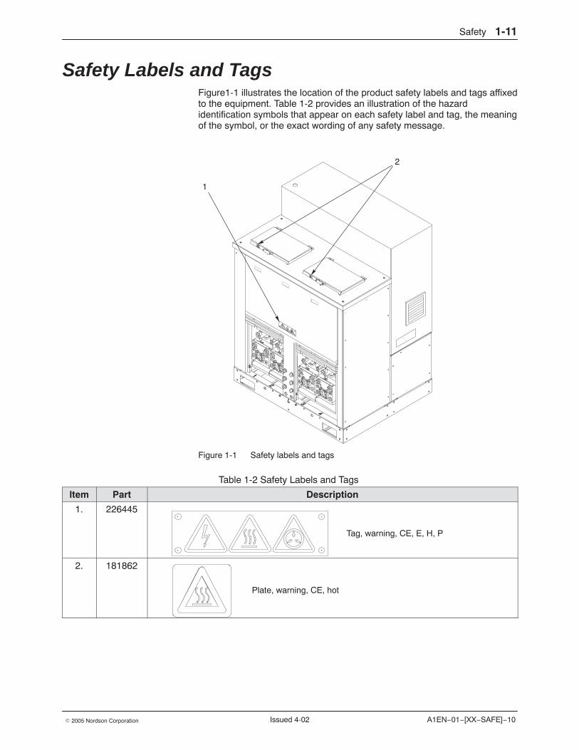
Safety Labels and Tags Figure1-1 illustrates the location of the product safety labels and tags affixedto the equipment. Table 1-2 provides an illustration of the hazardidentification symbols that appear on each safety label and tag, the meaningof the symbol, or the exact wording of any safety message.
2
1
Figure 1-1 Safety labels and tags
Table 1-2 Safety Labels and Tags
Item Part Description
1. 226445
Tag, warning, CE, E, H, P
2. 181862
Plate, warning, CE, hot

Safety1-12
A1EN−01−[XX−SAFE]−10 � 2005 Nordson CorporationIssued 4-02
Description 2-1
Part 331149G� 2005 Nordson Corporation
Section 2Description
Introduction This manual describes how to install, operate, and service an AdvancedTechnology System (ATS) adhesive melter. It also explains how the melterworks with other major components of a hot melt system.
ATS melters are configurable, which means each melter is constructedaccording to specific choices made when it was ordered. ATS melters mayhave:
� a 25-kg, 50-kg, or 100-kg single tank (single melters); a 50-kg,100-kg, or 200-kg dual tank (dual melters); or two 25-kg, 50-kg, or100-kg single tanks (twin melters)
� one to four single-stream or dual-stream pumps of varying outputrates, allowing the possibility of 1−8 adhesive streams
� one to four 10:1 or 20:1 reducer-ratio motor assemblies (drives),depending on the number of pumps
� pressure control valves, flow control valves, or air-operated pressurecontrol valves for recirculation pressure adjustment
� post-filter pressure monitoring for all adhesive streams and optionalpre-filter pressure monitoring for all adhesive streams
� optional level indication and level control
To determine the exact configuration of your melter, refer to Explanation ofthe Melter Configuration Code in Section 13, Technical Data.
Description2-2
Part 331149G � 2005 Nordson Corporation
Product Description Nordson ATS adhesive melters are used in conjunction with Nordson hotmelt hoses and applicators to create a hot melt application system.
The melter liquifies solid-form hot melt and maintains the hot melt at thedesired temperature. When the applicators are activated, the melter pumpsthe liquified hot melt through the hoses and out the applicator nozzles,where it is commonly applied to the surface of a product.
Intended Use ATS melters are specifically designed to:
� melt and pump solid-form hot melt materials that are engineered tobe liquified and extruded at temperatures below 230 �C (450 �F)
� be used with compatible hot melt hoses and applicators that aremanufactured by Nordson Corporation
� be used in non-explosive environments
Limitations of Use Use ATS melters only for the purpose for which they are designed.ATS melters should not be used:
� to melt or pump polyurethane reactive hot melt materials or anyother material that creates a health or safety hazard when heated
� in environments that will require the melter to be cleaned using awater wash or spray
Description 2-3
Part 331149G� 2005 Nordson Corporation
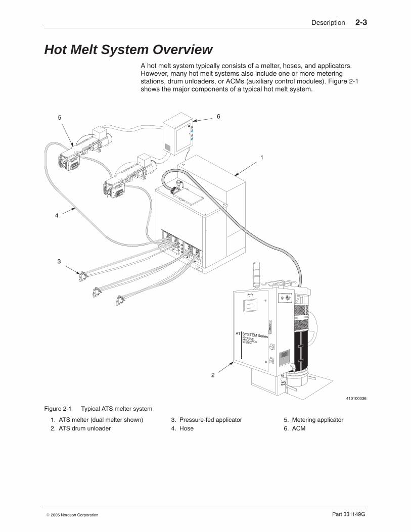
Hot Melt System Overview A hot melt system typically consists of a melter, hoses, and applicators.However, many hot melt systems also include one or more meteringstations, drum unloaders, or ACMs (auxiliary control modules). Figure 2-1shows the major components of a typical hot melt system.
410100036
1
4
5
3
6
2
ÎÎÎÎ
Figure 2-1 Typical ATS melter system
1. ATS melter (dual melter shown)2. ATS drum unloader
3. Pressure-fed applicator4. Hose
5. Metering applicator6. ACM
Description2-4
Part 331149G � 2005 Nordson Corporation
Melter The ATS melter is the main component of a hot melt system. The meltermelts adhesive and delivers it through heated hoses to applicators thatdispense the adhesive onto a product. The melter also provides power toheat the hoses and applicators. The melter’s control system, usually aprogrammable logic controller (PLC), controls the temperature of theadhesive inside the melter, hoses, and applicators and the rate at which theadhesive is pumped. The next part of this section, Melter Overview,provides more information about the melter.
Hoses Heated hoses carry the adhesive in a hot melt system from one componentto another. Hoses may function in three ways: as supply hoses, as returnhoses, or as cascade hoses. Supply hoses carry adhesive from a meltermanifold to remotely located applicators or metering stations. If the meltermanifold is externally circulating, return hoses recirculate undispensedadhesive back to the melter. In cases where adhesive is supplied from thesame melter manifold to more than one metering applicator or meteringstation, cascade hoses transfer the adhesive from the outlet of one meteringapplicator or metering station to the inlet of another.
Applicators Applicators dispense adhesive onto a product or surface. Two types ofapplicators are typically used in ATS systems: metering applicators andpressure-fed applicators. A metering applicator has its own metering pumpand motor to control its adhesive output. A pressure-fed applicator does nothave a metering pump or a motor—it dispenses adhesive supplied by themelter’s metering pumps.
Description 2-5
Part 331149G� 2005 Nordson Corporation
Metering Stations A metering station is similar to a metering applicator except that it suppliesadhesive, through cascade hoses, to dispensing modules that are remotelylocated. The metering station performs the same function as a meteringapplicator while reducing the amount of space required for equipment onthe production line.
Drum Unloaders Drum unloaders are used for high-volume applications in which the supplyof heated adhesive in the melter must be consistently maintained. The drumunloader melts adhesive and transfers it to the melter hopper throughheated hoses. This eliminates the need for operators to manually refill themelter hopper with adhesive and enables the melter to maintain theadhesive at a more constant temperature.
ACMs ACMs (auxiliary control modules) are typically used to add temperature andmotor control zones to a system that has already used all the zonesavailable on the melter. ACMs can
� communicate with the melter control system, allowing you to use themelter control system’s operator interface to (1) control thetemperature of the heated zones that are connected to the ACM and(2) to control the speed of the pumps on the meteringapplicators/stations that are connected to the ACM
� provide the power to heat applicators and/or hoses
� receive safety interlock signals from the melter control system
The number of ACMs required in an ATS system is determined by thenumber of temperature and/or motor control zones that cannot be controlledby the melter. Because each hose uses one temperature control zone, eachpressure-fed applicator uses 1−4 temperature control zones, and eachmetering applicator or metering station uses 4−10 temperature controlzones, it is possible for a system to have more temperature control zonesthan the melter can accommodate. In addition, metering applicators andmetering stations must always be connected to an ACM that includes amotor controller. For more information on ACMs, refer to the ACM manual.
Description2-6
Part 331149G � 2005 Nordson Corporation
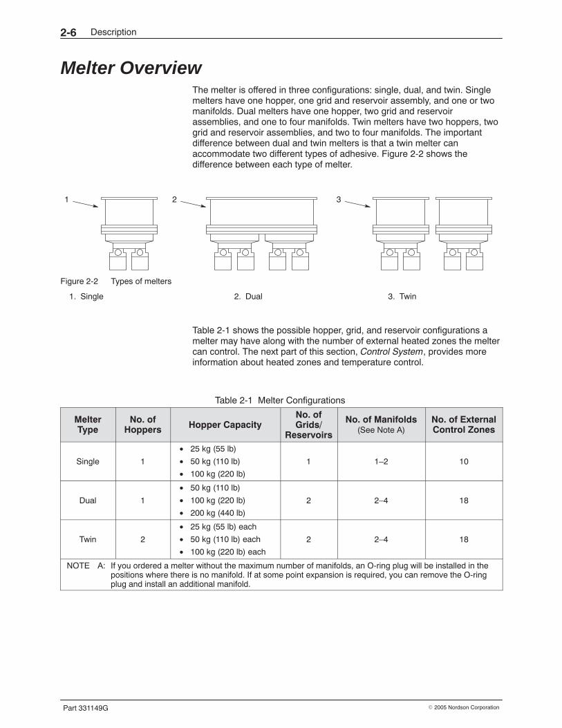
Melter Overview The melter is offered in three configurations: single, dual, and twin. Singlemelters have one hopper, one grid and reservoir assembly, and one or twomanifolds. Dual melters have one hopper, two grid and reservoirassemblies, and one to four manifolds. Twin melters have two hoppers, twogrid and reservoir assemblies, and two to four manifolds. The importantdifference between dual and twin melters is that a twin melter canaccommodate two different types of adhesive. Figure 2-2 shows thedifference between each type of melter.
1 2 3
Figure 2-2 Types of melters
1. Single 2. Dual 3. Twin
Table 2-1 shows the possible hopper, grid, and reservoir configurations amelter may have along with the number of external heated zones the meltercan control. The next part of this section, Control System, provides moreinformation about heated zones and temperature control.
Table 2-1 Melter Configurations
MelterType
No. ofHoppers Hopper Capacity
No. ofGrids/
Reservoirs
No. of Manifolds(See Note A)
No. of ExternalControl Zones
Single 1
• 25 kg (55 lb)
• 50 kg (110 lb)
• 100 kg (220 lb)
1 1–2 10
Dual 1
• 50 kg (110 lb)
• 100 kg (220 lb)
• 200 kg (440 lb)
2 2–4 18
Twin 2
• 25 kg (55 lb) each
• 50 kg (110 lb) each
• 100 kg (220 lb) each
2 2–4 18
NOTE A: If you ordered a melter without the maximum number of manifolds, an O-ring plug will be installed in thepositions where there is no manifold. If at some point expansion is required, you can remove the O-ringplug and install an additional manifold.
Description 2-7
Part 331149G� 2005 Nordson Corporation
All ATS melters have the following major systems with which you should befamiliar:
� the control system, which controls and monitors system operationand usually includes some type of operator interface
� the hydraulic system, which includes all the hoppers, grids,reservoirs, pumps, and manifolds on the melter
� the drive system, which includes the motors and reducers that drivethe pumps
Each of these systems is described in more detail in the following passages.Figures 2-3 and 2-4 show the key parts of a typical ATS melter.
6
1
2
3
4
5
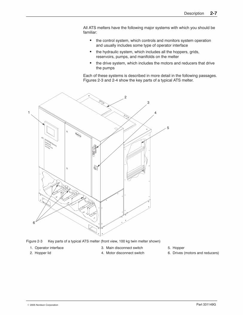
Figure 2-3 Key parts of a typical ATS melter (front view, 100 kg twin melter shown)
1. Operator interface2. Hopper lid
3. Main disconnect switch4. Motor disconnect switch
5. Hopper6. Drives (motors and reducers)
Description2-8
Part 331149G � 2005 Nordson Corporation
Melter Overview (contd)
1
2
3
4
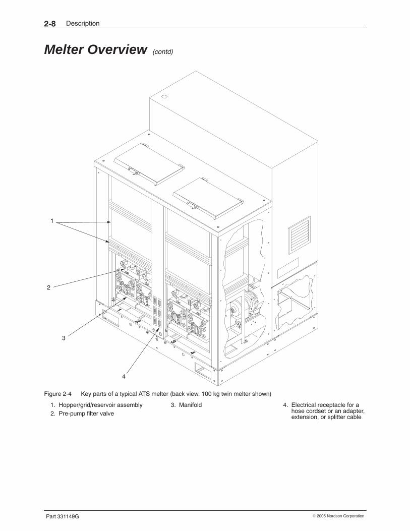
Figure 2-4 Key parts of a typical ATS melter (back view, 100 kg twin melter shown)
1. Hopper/grid/reservoir assembly2. Pre-pump filter valve
3. Manifold 4. Electrical receptacle for ahose cordset or an adapter,extension, or splitter cable
Description 2-9
Part 331149G� 2005 Nordson Corporation
Control System The melter will have either one of several available control systems suppliedby Nordson (such as the Allen-Bradley PLC-5, SLC-500, and ControlLogixprocessors or the Siemens PLC) or a control system you have supplied.The operator interface may be provided through a touchscreen on themelter, through the parent machine PLC, or through a remote control panelusing a Supervisory Control and Data Acquisition (SCADA) softwarepackage. Whatever the control system configuration of the melter is, thepurpose of the control system is to
� start and stop the hot melt system� take the hot melt system in or out of the setback mode� provide the power to heat the heated components (zones)� provide the power to run the pump motors� control the temperature setpoints of all melter heated zones� control the temperature setpoints of all ACM heated zones� control the speed of the melter pump motors� control the speed of metering applicator/station pump motors
(through an ACM)� monitor the system pressure� control the bulk fill process (if the level control option is used)� provide alarms
The only melter functions that are not controlled through the controlsystem’s operator interface are the system power and motor lockoutfunctions. There are mechanical disconnect switches for these functions onthe front of the melter, as shown in Figure 2-3. If an ACM is used, it hasseparate power and motor disconnect switches.
A heated zone, or temperature control zone, is any component that isheated and for which the temperature is controlled. Heated componentshave one or more heaters and a temperature-sensing device, such as aplatinum resistance temperature detector (RTD). Most heated zones alsohave an overtemperature thermoswitch or thermostat. The heaters for gridsand reservoirs are cast-in. Hoppers are heated by replacable heater strips.Manifolds are heated by a replaceable heater plate. Hoses are heated bynon-replaceable spirally wrapped resistive heating elements. Applicatorsare heated by replaceable cartridge-type heaters. The sensors andthermoswitches for all heated components (except hoses) are replaceable.
The heated zones on the melter are the hoppers, grids, reservoirs, andmanifolds. These are known as internal zones. Other heated zones includeeach hose and the adhesive manifolds and heated air manifolds onapplicators. These are known as external zones. Table 2-1 shows thenumber of external heated zones each type of melter can control.
Description2-10
Part 331149G � 2005 Nordson Corporation
Control System (contd)
The electrical cabinet in which the control system and most of the melter’selectrical components are housed is manufactured according to therequirements of each customer order. Refer to the electrical cabinetdocumentation provided with the melter to learn more about theconfiguration of the electrical cabinet on your melter.
Hydraulic System Adhesive is supplied to the melter, either manually or via a bulk-fill valve,through the hopper lid. The hopper, grid, and reservoir melt the adhesiveand supply it to the melter manifold, where the adhesive is then transferredby the pump inside the manifold to the supply hose. Each manifold on themelter is either a single-stream manifold or a dual-stream manifold. Asingle-stream manifold has a single-stream pump that supplies a singlemetered stream of adhesive. A dual-stream manifold has a dual-streampump that supplies two metered streams of adhesive. Refer to Table 2-1earlier in this section for the possible hopper, grid, reservoir, and manifoldconfigurations a melter may have.
A manifold may be either internally circulating or externally circulating.Internally circulating manifolds are used when applicators are fed by supplyhoses and have no return hoses. Externally circulating manifolds are usedwhen applicators are connected to the manifolds with both supply andreturn hoses. For a more detailed overview of the hydraulic system, refer toSection 8, Hydraulic System.
Drive System The drive system includes the motors and reducers that drive the melterpumps. A melter may have from one to four drives, depending on thenumber of pumps. The speed of the pump motors is controlled through thecontrol system. For a more detailed overview of the drive system, refer toSection 9, Drive System.
Installation 3-1
Part 331149G� 2005 Nordson Corporation
Section 3Installation
WARNING: Allow only personnel with appropriate training and experienceto operate or service the equipment. The use of untrained or inexperiencedpersonnel to operate or service the equipment can result in injury, includingdeath, to themselves and others, and damage to the equipment.
Introduction This section of the manual provides procedures for installing the melter andhoses. It does not include procedures for installing
� applicators� ACMs (if required)
Instead, it refers you to the manuals for these components at theappropriate place in the installation procedures.
NOTE: An ACM is a separate controller used in systems that require eitherthe control of an external motor (such as one on a metering applicator) orthe control of more external heated zones than the melter alone can control.
NOTE: Procedures for programming system settings and preparing thesystem for operation are in the next section, Setup.
Installation3-2
Part 331149G � 2005 Nordson Corporation
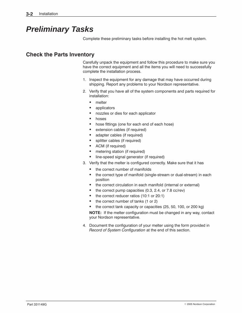
Preliminary Tasks Complete these preliminary tasks before installing the hot melt system.
Check the Parts Inventory Carefully unpack the equipment and follow this procedure to make sure youhave the correct equipment and all the items you will need to successfullycomplete the installation process.
1. Inspect the equipment for any damage that may have occurred duringshipping. Report any problems to your Nordson representative.
2. Verify that you have all of the system components and parts required forinstallation:
� melter� applicators� nozzles or dies for each applicator� hoses� hose fittings (one for each end of each hose)� extension cables (if required)� adapter cables (if required)� splitter cables (if required)� ACM (if required)� metering station (if required)� line-speed signal generator (if required)
3. Verify that the melter is configured correctly. Make sure that it has
� the correct number of manifolds� the correct type of manifold (single-stream or dual-stream) in each
position� the correct circulation in each manifold (internal or external)� the correct pump capacities (0.3, 2.4, or 7.8 cc/rev)� the correct reducer ratios (10:1 or 20:1)� the correct number of tanks (1 or 2)� the correct tank capacity or capacities (25, 50, 100, or 200 kg)
NOTE: If the melter configuration must be changed in any way, contactyour Nordson representative.
4. Document the configuration of your melter using the form provided inRecord of System Configuration at the end of this section.
Installation 3-3
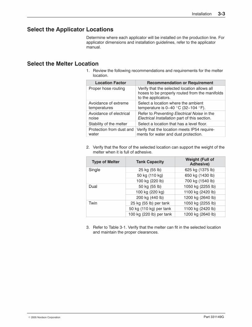
Part 331149G� 2005 Nordson Corporation
Select the Applicator Locations Determine where each applicator will be installed on the production line. Forapplicator dimensions and installation guidelines, refer to the applicatormanual.
Select the Melter Location 1. Review the following recommendations and requirements for the melter
location.
Location Factor Recommendation or RequirementProper hose routing Verify that the selected location allows all
hoses to be properly routed from the manifoldsto the applicators.
Avoidance of extremetemperatures
Select a location where the ambienttemperature is 0−40 �C (32−104 �F).
Avoidance of electricalnoise
Refer to Preventing Electrical Noise in theElectrical Installation part of this section.
Stability of the melter Select a location that has a level floor.Protection from dust andwater
Verify that the location meets IP54 require-ments for water and dust protection.
2. Verify that the floor of the selected location can support the weight of themelter when it is full of adhesive.
Type of Melter Tank Capacity Weight (Full ofAdhesive)
Single 25 kg (55 lb) 625 kg (1375 lb)Single50 kg (110 kg) 650 kg (1430 lb)100 kg (220 lb) 700 kg (1540 lb)
Dual 50 kg (55 lb) 1050 kg (2255 lb)Dual100 kg (220 kg) 1100 kg (2420 lb)200 kg (440 lb) 1200 kg (2640 lb)
Twin 25 kg (55 lb) per tank 1050 kg (2255 lb)Twin50 kg (110 kg) per tank 1100 kg (2420 lb)100 kg (220 lb) per tank 1200 kg (2640 lb)
3. Refer to Table 3-1. Verify that the melter can fit in the selected locationand maintain the proper clearances.
Installation3-4
Part 331149G � 2005 Nordson Corporation
Select the Melter Location (contd)
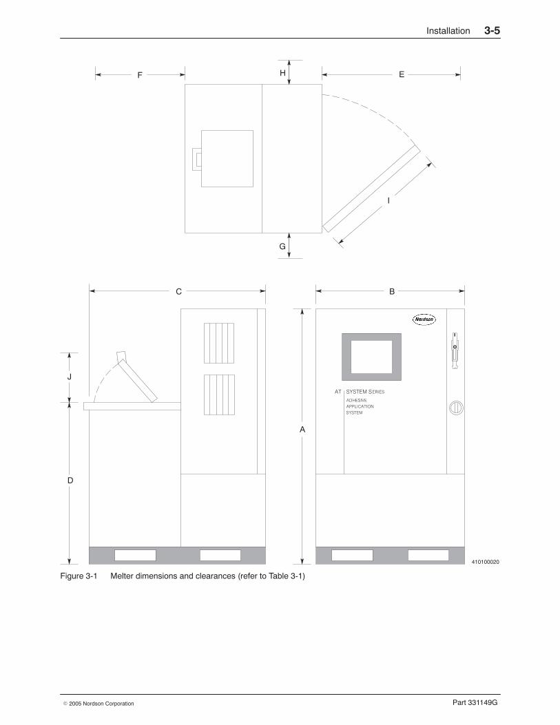
Table 3-1 Melter Dimensions and Clearances (see Figure 3-1)
Dimensions Single Melter Dual/Twin MelterA
Height of melter
without casters: 1630 mm (64 in.)
with casters: 1765 mm (69.5 in.)
without casters: 1780 mm (70.1 in.)
with casters: 1915 mm (75 in.)B
Width of melter917 mm (35 in.) 1350 mm (53 in.)
C
Depth of melter1100 mm (43 in.) 1100 mm (43 in.)
D
Height of mechanicalenclosure
small hopper without casters:1130 mm (44.5 in.)
small hopper with casters:1270 mm (50 in.)
small hopper without casters:1130 mm (44.5 in.)
small hopper with casters:1270 mm (50 in.)
large hopper without casters:1473 mm (58 in.)
large hopper with casters:1612 mm (63.5 in.)
large hopper without casters:1473 mm (58 in.)
large hopper with casters:1612 mm (63.5 in.)
ClearancesE
Front of melter1219 mm (48 in.) 1219 mm (48 in.)
F
Back of melter915 mm (36 in.) 915 mm (36 in.)
G
Left side 305 mm (12 in.) 305 mm (12 in.)
H
Right side305 mm (12 in.) 305 mm (12 in.)
I
Electrical cabinet door800 mm (31.5 in.)
left door: 635 mm (25 in.)
right door: 622 mm (24.5 in.)J
Hopper lid432 mm (17 in.) 432 mm (17 in.)
Installation 3-5
Part 331149G� 2005 Nordson Corporation
410100020
A
BC
D
EF
G
H
J
I
Figure 3-1 Melter dimensions and clearances (refer to Table 3-1)
Installation3-6
Part 331149G � 2005 Nordson Corporation
Mechanical Installation Use these procedures to install the system mechanically. Before performingthese procedures, complete the procedures in Preliminary Tasks.
Install the Applicators and the Melter 1. Install the applicators on the production line in the selected locations.
Refer to the applicator manuals for installation procedures.
2. If the system includes a metering station, refer to the manual for thatequipment to install the metering station.
3. If the system includes an ACM, refer to the ACM manual to install theACM.
4. Move the melter to the selected location using a suitable forklift. For adual or twin melter, the forklift must have a separation between the forks(from the inside edge of one fork to the other) of at least 840 mm(33 in.).
NOTE: A single melter weighs 600 kg (1,320 lb) and a dual or twinmelter weighs 1000 kg (2,200 lb).
5. (melters mounted on casters only) Attach the four casters to the base ofthe melter while the melter is held up by the forklift.
NOTE: Casters are available in a kit. Refer to Optional Accessories inSection 12, Parts, for the kit part number.
6. Set the melter on the floor and
� (melters with casters) lock the casters� (melters without casters) insert shims, if needed, to level the unit
NOTE: It is not necessary to bolt the melter to the floor.
Install a Line-Speed Generator If the melter system is equipped with a dedicated line-speed signalgenerator, install it on the production line so that the ratio of parent-machineshaft rotation to tachometer shaft rotation is 1:1. The tachometer shaftshould make one revolution for each revolution of the parent-machine shaft.
Installation 3-7
Part 331149G� 2005 Nordson Corporation
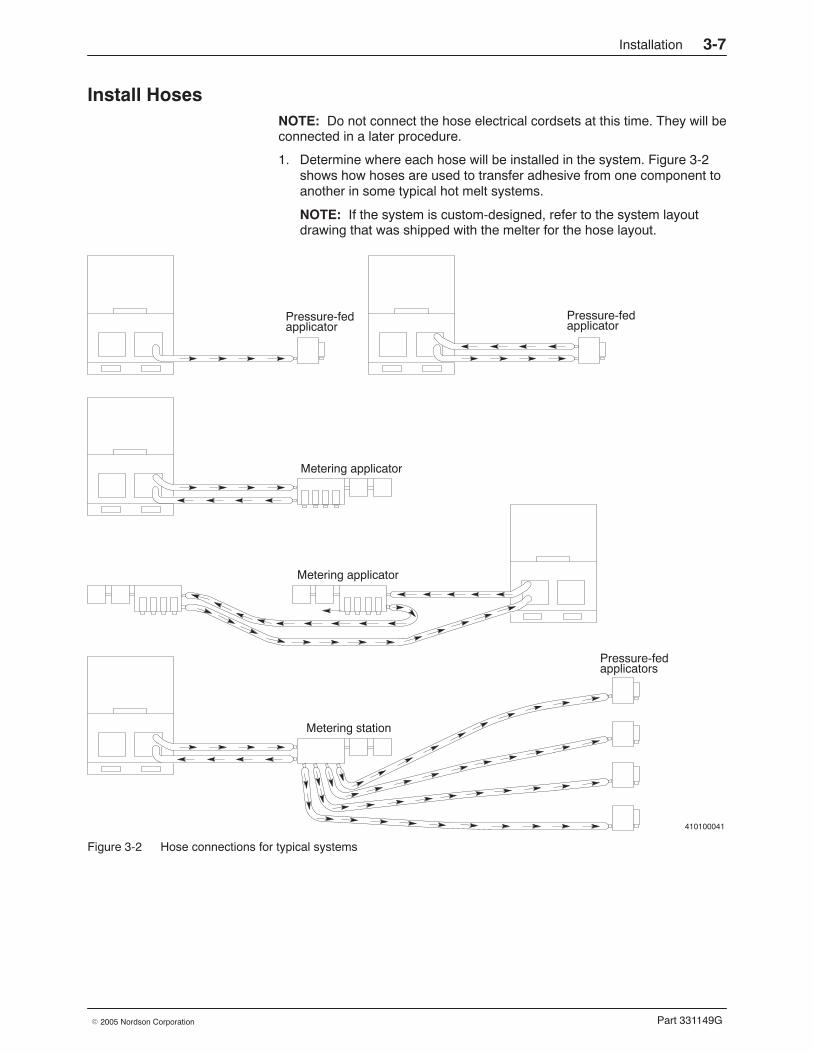
Install Hoses NOTE: Do not connect the hose electrical cordsets at this time. They will beconnected in a later procedure.
1. Determine where each hose will be installed in the system. Figure 3-2shows how hoses are used to transfer adhesive from one component toanother in some typical hot melt systems.
NOTE: If the system is custom-designed, refer to the system layoutdrawing that was shipped with the melter for the hose layout.
410100041
Pressure-fedapplicator
Pressure-fedapplicator
Metering applicator
Metering applicator
Pressure-fedapplicators
Metering station
Figure 3-2 Hose connections for typical systems
Installation3-8
Part 331149G � 2005 Nordson Corporation
Install Hoses (contd)
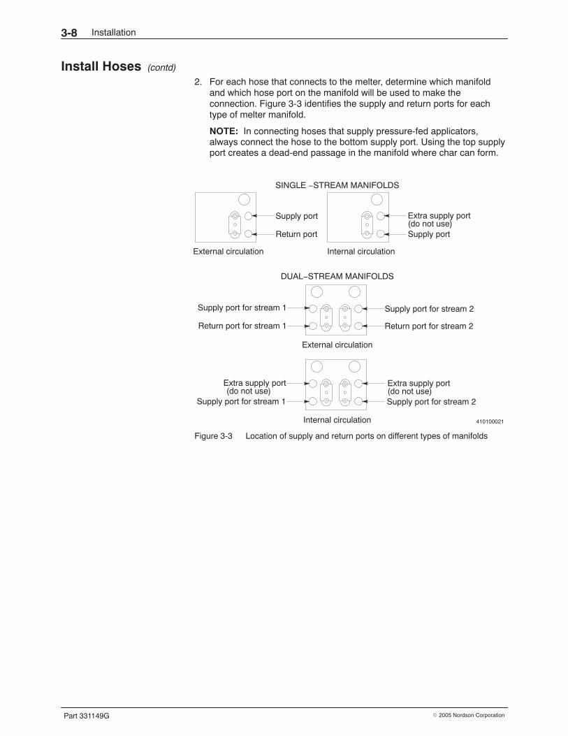
2. For each hose that connects to the melter, determine which manifoldand which hose port on the manifold will be used to make theconnection. Figure 3-3 identifies the supply and return ports for eachtype of melter manifold.
NOTE: In connecting hoses that supply pressure-fed applicators,always connect the hose to the bottom supply port. Using the top supplyport creates a dead-end passage in the manifold where char can form.
410100021
Supply port
Return port
External circulation
Extra supply port
Supply port
Internal circulation
Supply port for stream 1
Return port for stream 1
Supply port for stream 2
Return port for stream 2
Extra supply port
SINGLE −STREAM MANIFOLDS
DUAL−STREAM MANIFOLDS
External circulation
Internal circulation
(do not use)Extra supply port(do not use)Supply port for stream 2Supply port for stream 1
(do not use)
Figure 3-3 Location of supply and return ports on different types of manifolds
Installation 3-9
Part 331149G� 2005 Nordson Corporation
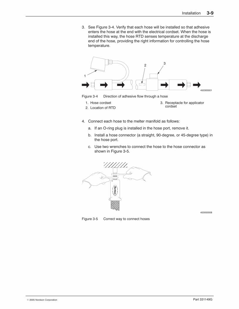
3. See Figure 3-4. Verify that each hose will be installed so that adhesiveenters the hose at the end with the electrical cordset. When the hose isinstalled this way, the hose RTD senses temperature at the dischargeend of the hose, providing the right information for controlling the hosetemperature.
450300001
32
1
Figure 3-4 Direction of adhesive flow through a hose
1. Hose cordset2. Location of RTD
3. Receptacle for applicatorcordset
4. Connect each hose to the melter manifold as follows:
a. If an O-ring plug is installed in the hose port, remove it.
b. Install a hose connector (a straight, 90-degree, or 45-degree type) inthe hose port.
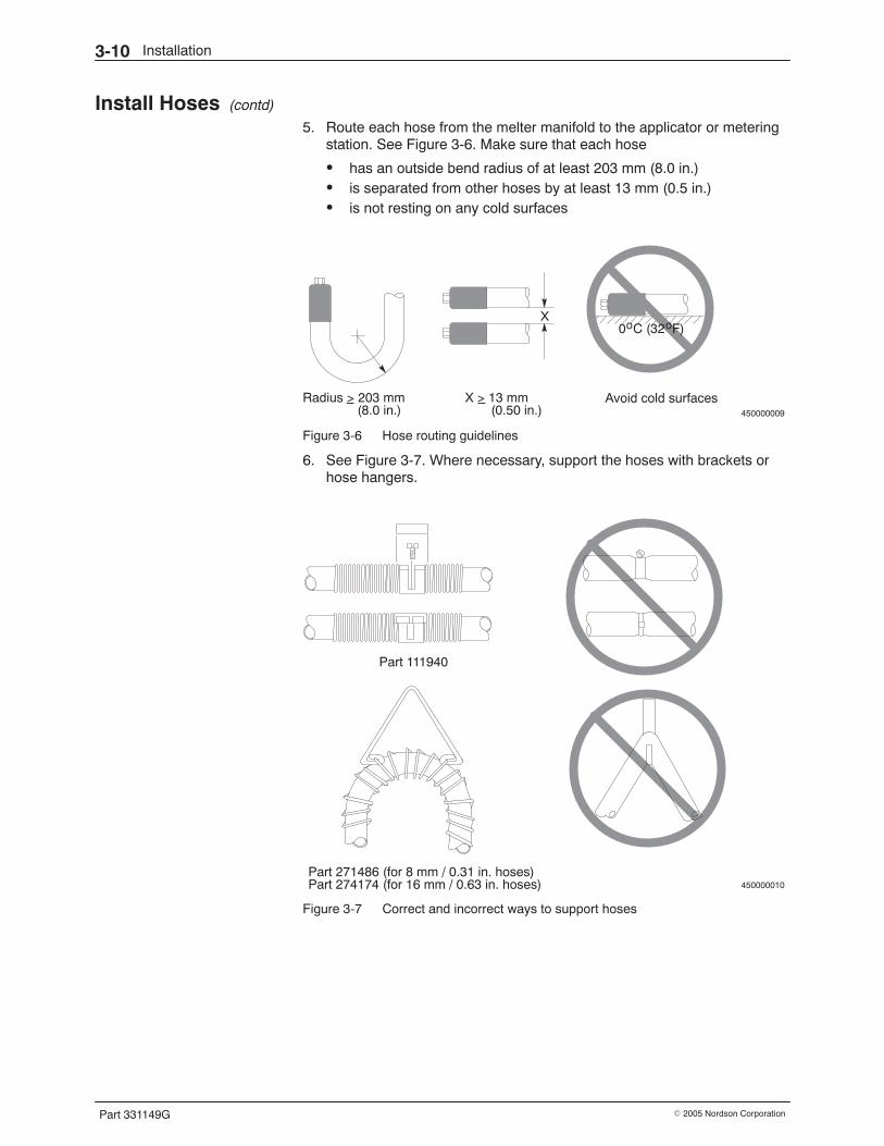
c. Use two wrenches to connect the hose to the hose connector asshown in Figure 3-5.
450000008
ÎÎÎÎÎ
Figure 3-5 Correct way to connect hoses
Installation3-10
Part 331149G � 2005 Nordson Corporation
Install Hoses (contd)
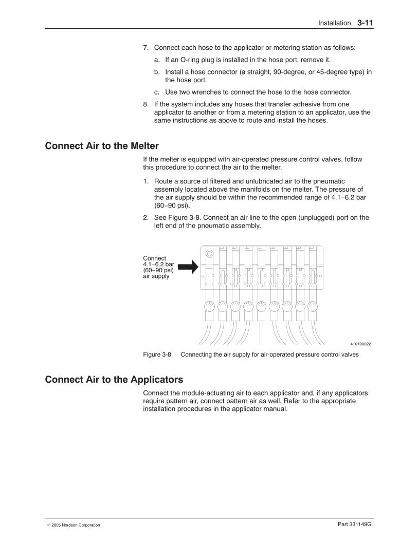
5. Route each hose from the melter manifold to the applicator or meteringstation. See Figure 3-6. Make sure that each hose
� has an outside bend radius of at least 203 mm (8.0 in.)� is separated from other hoses by at least 13 mm (0.5 in.)� is not resting on any cold surfaces
450000009
X
Radius > 203 mm(8.0 in.)
_ X > 13 mm_(0.50 in.)
Avoid cold surfaces
0 C (32 F)o o
Figure 3-6 Hose routing guidelines
6. See Figure 3-7. Where necessary, support the hoses with brackets orhose hangers.
450000010
Part 111940
Part 271486 (for 8 mm / 0.31 in. hoses)Part 274174 (for 16 mm / 0.63 in. hoses)
Figure 3-7 Correct and incorrect ways to support hoses
Installation 3-11
Part 331149G� 2005 Nordson Corporation
7. Connect each hose to the applicator or metering station as follows:
a. If an O-ring plug is installed in the hose port, remove it.
b. Install a hose connector (a straight, 90-degree, or 45-degree type) inthe hose port.
c. Use two wrenches to connect the hose to the hose connector.
8. If the system includes any hoses that transfer adhesive from oneapplicator to another or from a metering station to an applicator, use thesame instructions as above to route and install the hoses.
Connect Air to the Melter If the melter is equipped with air-operated pressure control valves, followthis procedure to connect the air to the melter.
1. Route a source of filtered and unlubricated air to the pneumaticassembly located above the manifolds on the melter. The pressure ofthe air supply should be within the recommended range of 4.1−6.2 bar(60−90 psi).
2. See Figure 3-8. Connect an air line to the open (unplugged) port on theleft end of the pneumatic assembly.
410100022
Connect4.1−6.2 bar(60−90 psi)air supply
Figure 3-8 Connecting the air supply for air-operated pressure control valves
Connect Air to the Applicators Connect the module-actuating air to each applicator and, if any applicatorsrequire pattern air, connect pattern air as well. Refer to the appropriateinstallation procedures in the applicator manual.
Installation3-12
Part 331149G � 2005 Nordson Corporation
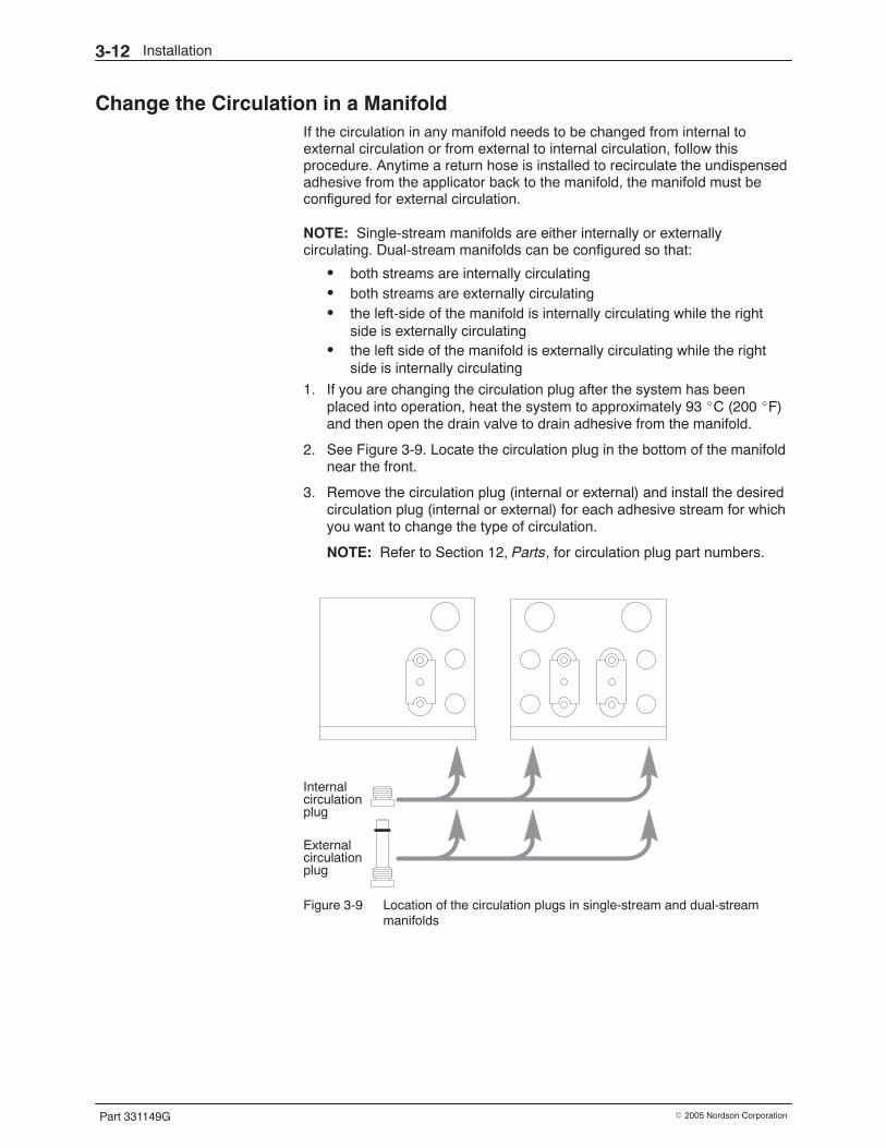
Change the Circulation in a Manifold If the circulation in any manifold needs to be changed from internal toexternal circulation or from external to internal circulation, follow thisprocedure. Anytime a return hose is installed to recirculate the undispensedadhesive from the applicator back to the manifold, the manifold must beconfigured for external circulation.
NOTE: Single-stream manifolds are either internally or externallycirculating. Dual-stream manifolds can be configured so that:
� both streams are internally circulating� both streams are externally circulating� the left-side of the manifold is internally circulating while the right
side is externally circulating� the left side of the manifold is externally circulating while the right
side is internally circulating
1. If you are changing the circulation plug after the system has beenplaced into operation, heat the system to approximately 93 �C (200 �F)and then open the drain valve to drain adhesive from the manifold.
2. See Figure 3-9. Locate the circulation plug in the bottom of the manifoldnear the front.
3. Remove the circulation plug (internal or external) and install the desiredcirculation plug (internal or external) for each adhesive stream for whichyou want to change the type of circulation.
NOTE: Refer to Section 12, Parts, for circulation plug part numbers.
Internal
External
circulationplug
circulationplug
Figure 3-9 Location of the circulation plugs in single-stream and dual-streammanifolds
Installation 3-13
Part 331149G� 2005 Nordson Corporation
Connect a Bulk Fill System to the Melter If applicable, connect a bulk fill system to the melter. Refer to the bulk fillsystem manual for installation procedures. Return here to continue.
Electrical Installation Use these procedures to install the system electrically. Before performingthese procedures, complete the procedures in Preliminary Tasks andMechanical Installation.
Prevent Electrical Noise Follow the guidelines below when routing cables, cordsets, and wiring toensure that the equipment will operate as intended.
� Verify that all equipment is properly grounded.
� Keep all wire runs and cabling as short as possible.
� Avoid running wires parallel to conductors that carry high current,especially in the same conduit or wire trough.
� Avoid routing wiring and cables close to brush-type motors.
Installation3-14
Part 331149G � 2005 Nordson Corporation
Connect Hose and Applicator Cordsets Use this procedure to make the electrical connections between the externalheated zones and the melter. The cordsets and cables used to do this canbe identified by the shape of their connectors: square (applicator adhesivezone), round (applicator air zone), and rectangular (hose zone).
1. See Figure 3-10. Determine the type of hoses used in the system:M-style hoses or universal hoses. M-style hoses have a receptacle atthe discharge end of the hose for connecting the applicator’s heatedadhesive zone. Universal hoses do not have this receptacle.
450000011
ÄÄÄÄÄÄ
ÄÄÄÄÄÄÄÄÄÄÄÄÄÄÄ
ÄÄÄÄÄÄÄÄÄ
M-style hose
Universal hose
Receptacle forheated adhesive zone
Figure 3-10 Examples of an M-style and a Universal hose
2. Count the melter’s receptacles for connecting external heated zones.Then use the following table to determine the maximum number ofexternal heated zones that can be connected to the melter
� without using splitter cables� using splitter cables
No. of Connectorson Melter
Maximum Zones(using no splitter cables)
Maximum Zones(using splitter cables)
5 5 109 9 18
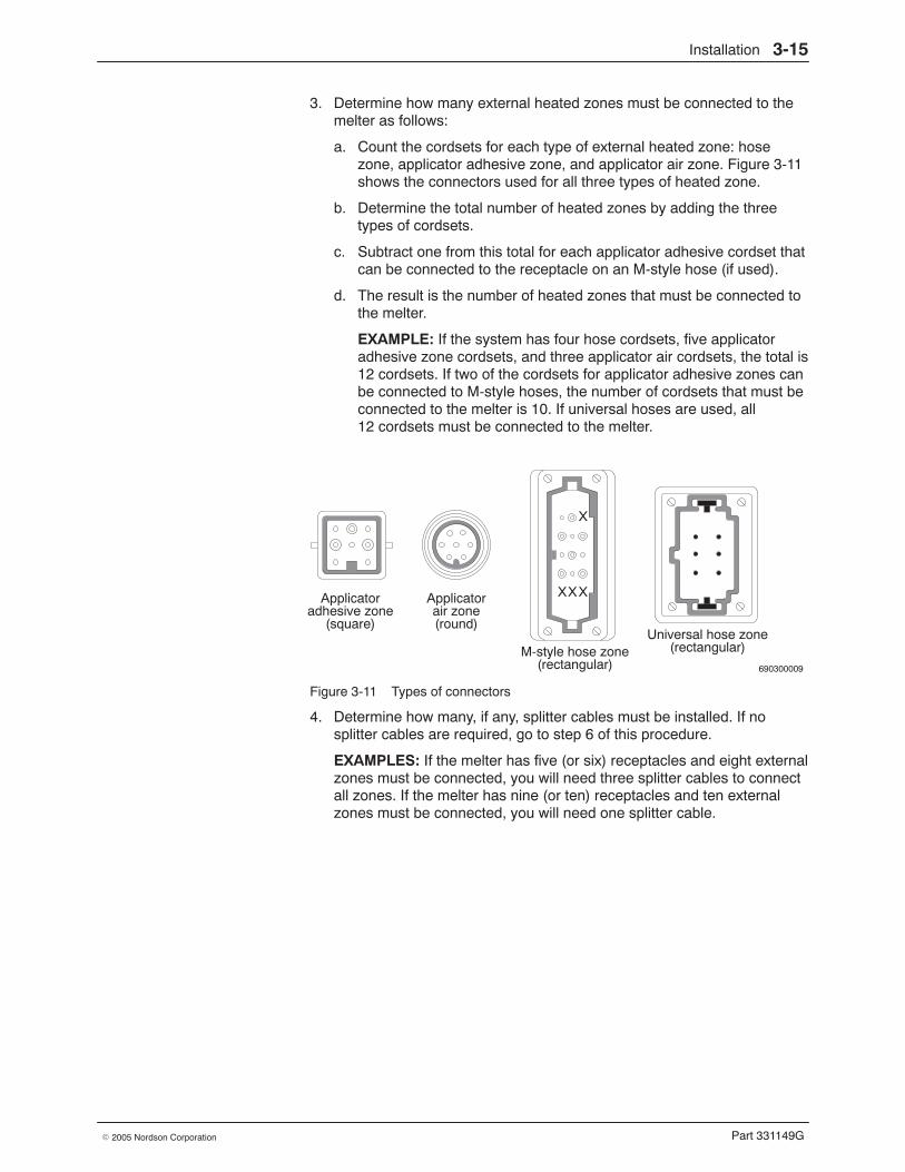
Installation 3-15
Part 331149G� 2005 Nordson Corporation
3. Determine how many external heated zones must be connected to themelter as follows:
a. Count the cordsets for each type of external heated zone: hosezone, applicator adhesive zone, and applicator air zone. Figure 3-11shows the connectors used for all three types of heated zone.
b. Determine the total number of heated zones by adding the threetypes of cordsets.
c. Subtract one from this total for each applicator adhesive cordset thatcan be connected to the receptacle on an M-style hose (if used).
d. The result is the number of heated zones that must be connected tothe melter.
EXAMPLE: If the system has four hose cordsets, five applicatoradhesive zone cordsets, and three applicator air cordsets, the total is12 cordsets. If two of the cordsets for applicator adhesive zones canbe connected to M-style hoses, the number of cordsets that must beconnected to the melter is 10. If universal hoses are used, all12 cordsets must be connected to the melter.
690300009
Applicator Applicator
X
XXX
M-style hose zoneUniversal hose zone
adhesive zone(square)
air zone(round)
(rectangular)(rectangular)
Figure 3-11 Types of connectors
4. Determine how many, if any, splitter cables must be installed. If nosplitter cables are required, go to step 6 of this procedure.
EXAMPLES: If the melter has five (or six) receptacles and eight externalzones must be connected, you will need three splitter cables to connectall zones. If the melter has nine (or ten) receptacles and ten externalzones must be connected, you will need one splitter cable.
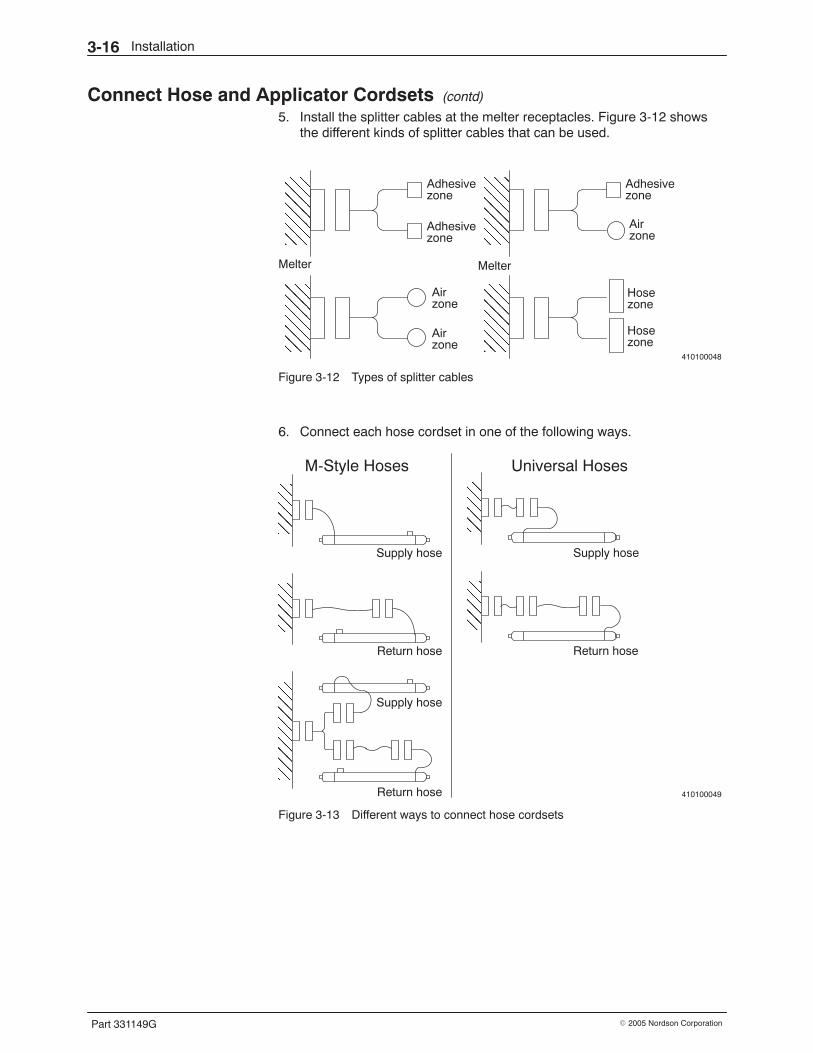
Installation3-16
Part 331149G � 2005 Nordson Corporation
Connect Hose and Applicator Cordsets (contd)
5. Install the splitter cables at the melter receptacles. Figure 3-12 showsthe different kinds of splitter cables that can be used.
410100048
ÌÌÌÌÌÌÌÌÌÌÌÌÌÌÌÌÌÌÌÌÌÌÌÌÌÌÌÌÌÌ
ÌÌÌÌÌÌÌÌÌÌÌÌÌÌÌÌÌÌÌÌ
Adhesivezone
Airzone
Hosezone
Melter
Adhesivezone
Airzone
Melter
Hosezone
Adhesivezone
Airzone
Figure 3-12 Types of splitter cables
6. Connect each hose cordset in one of the following ways.
410100049
ÌÌÌÌÌÌÌÌ
ÌÌÌÌÌÌÌÌ
ÌÌÌÌÌÌ
ÌÌÌÌÌÌ
ÌÌÌÌÌÌÌÌÌÌÌÌ
M-Style Hoses Universal Hoses
Supply hose
Return hose
Supply hose
Return hose
Supply hose
Return hose
Figure 3-13 Different ways to connect hose cordsets
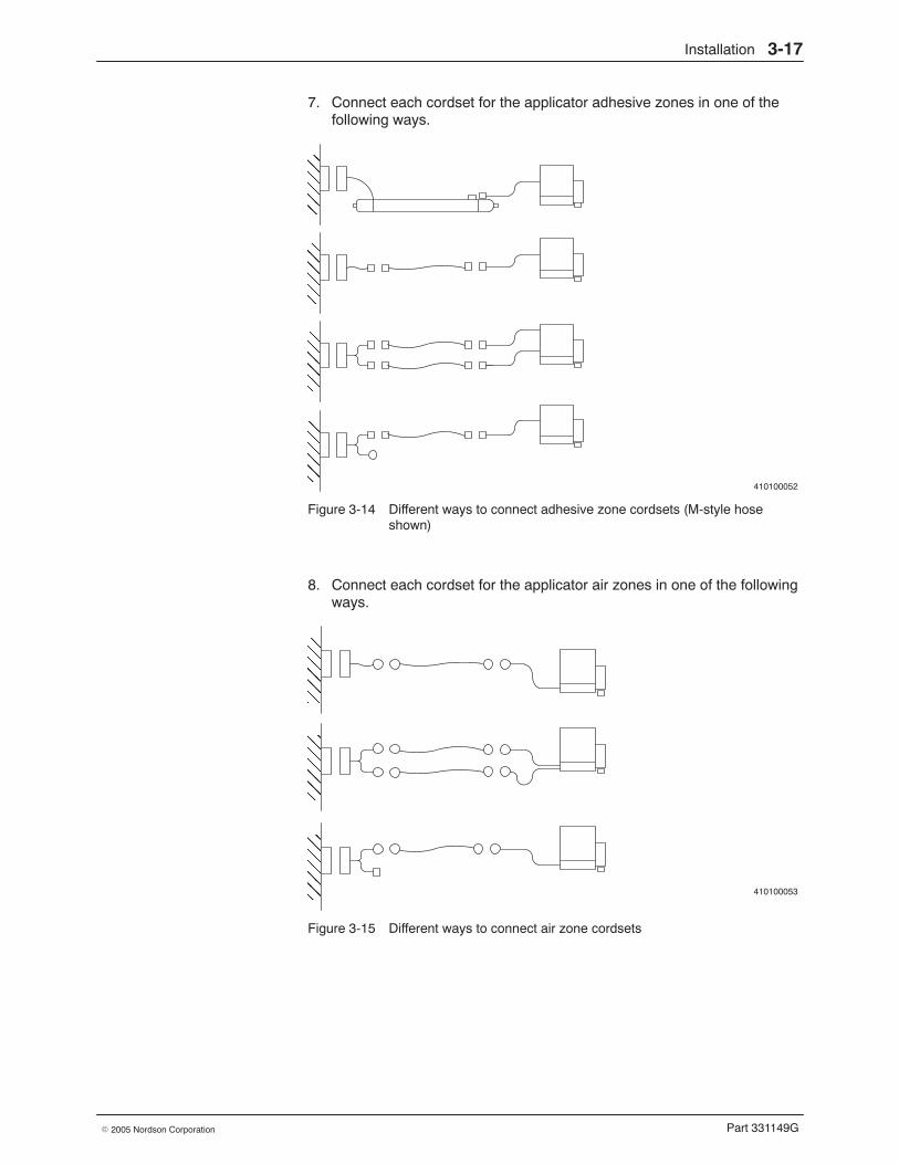
Installation 3-17
Part 331149G� 2005 Nordson Corporation
7. Connect each cordset for the applicator adhesive zones in one of thefollowing ways.
410100052
ÌÌÌÌÌÌÌÌÌÌÌÌÌÌÌÌÌÌÌÌÌÌÌÌÌÌÌÌÌÌÌÌ
Figure 3-14 Different ways to connect adhesive zone cordsets (M-style hoseshown)
8. Connect each cordset for the applicator air zones in one of the followingways.
410100053
ÌÌÌÌÌÌÌÌÌÌÌÌÌÌÌÌÌÌÌÌÌÌÌÌ
Figure 3-15 Different ways to connect air zone cordsets
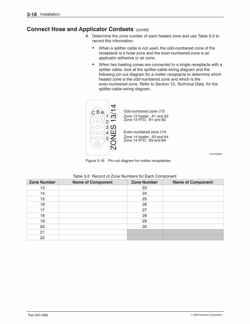
Installation3-18
Part 331149G � 2005 Nordson Corporation
Connect Hose and Applicator Cordsets (contd)
9. Determine the zone number of each heated zone and use Table 3-2 torecord this information.
� When a splitter cable is not used, the odd-numbered zone of thereceptacle is a hose zone and the even-numbered zone is anapplicator adhesive or air zone.
� When two heating zones are connected to a single receptacle with asplitter cable, look at the splitter-cable wiring diagram and thefollowing pin-out diagram for a melter receptacle to determine whichheated zone is the odd-numbered zone and which is theeven-numbered zone. Refer to Section 12, Technical Data, for thesplitter-cable wiring diagram.
410102004
ZO
NE
S 1
3/14 Odd-numbered zone (13)
Zone 13 heater: A1 and A2Zone 13 RTD: B1 and B2
Even-numbered zone (14)Zone 14 heater: A3 and A4Zone 14 RTD: B3 and B4
C B A12345
Figure 3-16 Pin-out diagram for melter receptacles
Table 3-2 Record of Zone Numbers for Each Component
Zone Number Name of Component Zone Number Name of Component13 2314 2415 2516 2617 2718 2819 2920 302122
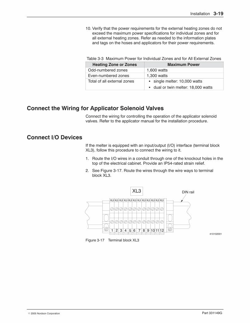
Installation 3-19
Part 331149G� 2005 Nordson Corporation
10. Verify that the power requirements for the external heating zones do notexceed the maximum power specifications for individual zones and forall external heating zones. Refer as needed to the information platesand tags on the hoses and applicators for their power requirements.
Table 3-3 Maximum Power for Individual Zones and for All External Zones
Heating Zone or Zones Maximum PowerOdd-numbered zones 1,600 wattsEven-numbered zones 1,300 wattsTotal of all external zones � single melter: 10,000 watts
� dual or twin melter: 18,000 watts
Connect the Wiring for Applicator Solenoid Valves Connect the wiring for controlling the operation of the applicator solenoidvalves. Refer to the applicator manual for the installation procedure.
Connect I/O Devices If the melter is equipped with an input/output (I/O) interface (terminal blockXL3), follow this procedure to connect the wiring to it.
1. Route the I/O wires in a conduit through one of the knockout holes in thetop of the electrical cabinet. Provide an IP54-rated strain relief.
2. See Figure 3-17. Route the wires through the wire ways to terminalblock XL3.
410102001
XL3
1 2 3 4 5 6 7 8 9 10 1112
XL3 XL3 XL3 XL3 XL3 XL3 XL3 XL3 XL3 XL3 XL3 XL3
DIN rail
Figure 3-17 Terminal block XL3
Installation3-20
Part 331149G � 2005 Nordson Corporation
Connect I/O Devices (contd)
3. Make the appropriate connections for each one of the I/O capabilitiesyou plan to use. The connections for each capability are shown inTable 3-4.
Table 3-4 Wiring Connections for I/O Capabilities
I/O Capability Explanation Terminals at XL3System Ready Sends a signal when all melter heating zones are up to
temperature and the system is ready to pump adhesive1 and 2
Alarm Sends a signal anytime an alarm occurs in the hot melt system 3 and 424 VDC Provides 24 VDC power 5 (common) and 12
(+24 V)Motor 4start/stop
Provides the ability to start or stop melter motor no. 4 remotely 6
Motor 3start/stop
Provides the ability to start or stop melter motor no. 3 remotely 7
Motor 2start/stop
Provides the ability to start or stop melter motor no. 2 remotely 8
Motor 1start/stop
Provides the ability to start or stop melter motor no. 1 remotely 9
Line-speedsignal input
Supplies the 0−10 VDC line-speed signal to the melter controlsystem
10 (+ VDC) and 11(common)
Install a Network Cable If you plan to link the melter system to a communications network, followthis procedure to connect the network cable.
1. Route the network cable through one of the knockout holes in the top ofthe electrical cabinet. Provide an IP54-rated strain relief.
2. Connect the network cable to the PLC or network card.
3. If the system is equipped with an ACM, refer to the ACM manual forprocedures for making the ACM network connections.
Installation 3-21
Part 331149G� 2005 Nordson Corporation
Connect Power
WARNING: Risk of equipment damage, personal injury, or death.Disconnect and lock out electrical power.
1. Disconnect and lock out electrical power at the plant circuit breaker.
CAUTION: Risk of equipment damage. Do not connect the melter to a linevoltage other than the voltage stated on the ID plate.
2. Route a service line that meets the following requirements to the melter:
Melter Type Service Current Draw at200−240 VAC
Current Draw at400 VAC Wire Size
Single 200−240 VAC Δ, 3 ∅,50/60 Hz
60 A 35 A 16 mm2 (6 AWG)with at least a105 �C (221 �F)Dual or twin 380−415 VAC Wye
(with neutral), 50/60 Hz100 A 64 A 105 �C (221 �F)
rating
3. Remove the knockout for the electrical service line. It is located on top ofthe electrical cabinet on the right side.
4. Route the service line into the cabinet. Provide an IP54-rated strainrelief.
5. See Figure 3-18. Connect L1, L2, and L3 to terminals 2, 4, and 6 oncircuit breaker 1Q21.
6. Connect the ground wire to ground stud PE.
410102002
2 4 6
1 3 5
1Q211Z71
L1 L2 L3G
PE
Figure 3-18 Electrical service line connections
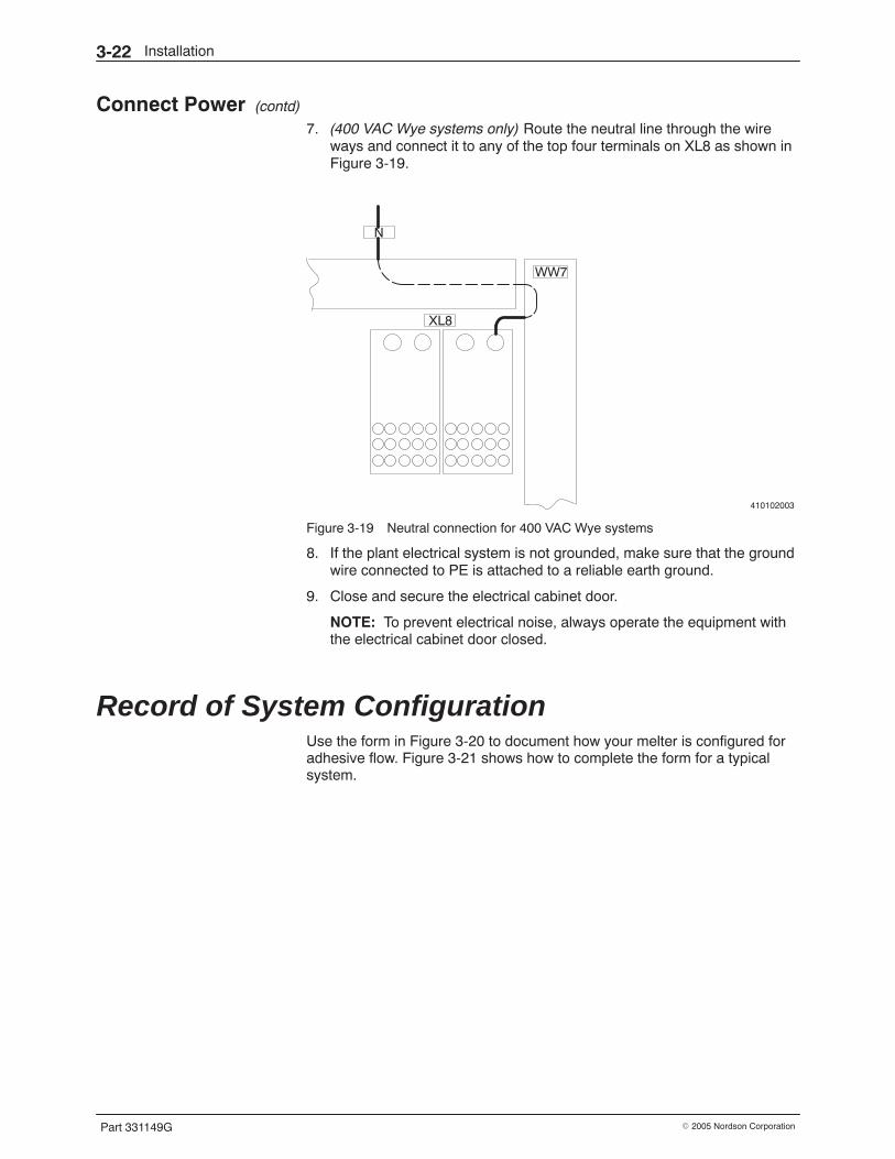
Installation3-22
Part 331149G � 2005 Nordson Corporation
Connect Power (contd)
7. (400 VAC Wye systems only) Route the neutral line through the wireways and connect it to any of the top four terminals on XL8 as shown inFigure 3-19.
410102003
N
XL8
WW7
Figure 3-19 Neutral connection for 400 VAC Wye systems
8. If the plant electrical system is not grounded, make sure that the groundwire connected to PE is attached to a reliable earth ground.
9. Close and secure the electrical cabinet door.
NOTE: To prevent electrical noise, always operate the equipment withthe electrical cabinet door closed.
Record of System Configuration Use the form in Figure 3-20 to document how your melter is configured foradhesive flow. Figure 3-21 shows how to complete the form for a typicalsystem.
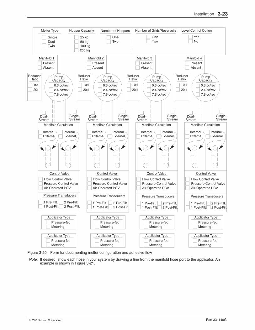
Installation 3-23
Part 331149G� 2005 Nordson Corporation
Hopper Capacity
25 kg50 kg100 kg200 kg
Manifold 1
PresentAbsent
ReducerRatio
10:1
20:1
PumpCapacity
0.3 cc/rev2.4 cc/rev7.8 cc/rev
Dual-Stream
Single-Stream
Manifold Circulation
InternalExternal
Control Valve
Flow Control ValvePressure Control ValveAir-Operated PCV
InternalExternal
Applicator Type
Pressure-fedMetering
ReducerRatio
10:1
20:1
PumpCapacity
0.3 cc/rev2.4 cc/rev7.8 cc/rev
Dual-Stream
Single-Stream
Manifold Circulation
InternalExternal
Control Valve
Flow Control ValvePressure Control ValveAir-Operated PCV
InternalExternal
Applicator Type
Pressure-fedMetering
ReducerRatio
10:1
20:1
PumpCapacity
0.3 cc/rev2.4 cc/rev7.8 cc/rev
Dual-Stream
Single-Stream
Manifold Circulation
InternalExternal
Control Valve
Flow Control ValvePressure Control ValveAir-Operated PCV
InternalExternal
Applicator Type
Pressure-fedMetering
ReducerRatio
10:1
20:1
PumpCapacity
0.3 cc/rev2.4 cc/rev7.8 cc/rev
Dual-Stream
Single-Stream
Manifold Circulation
InternalExternal
Control Valve
Flow Control ValvePressure Control ValveAir-Operated PCV
InternalExternal
Applicator Type
Pressure-fedMetering
Number of Grids/Reservoirs Level Control Option
Manifold 2
PresentAbsent
Manifold 3
PresentAbsent
Manifold 4
PresentAbsent
OneTwo
YesNo
Number of Hoppers
OneTwo
Pressure Transducers
1 Pre-Filt.1 Post-Filt.
2 Pre-Filt.2 Post-Filt.
Pressure Transducers
1 Pre-Filt.1 Post-Filt.
2 Pre-Filt.2 Post-Filt.
Pressure Transducers
1 Pre-Filt.1 Post-Filt.
2 Pre-Filt.2 Post-Filt.
Pressure Transducers
1 Pre-Filt.1 Post-Filt.
2 Pre-Filt.2 Post-Filt.
Melter Type
SingleDualTwin
Applicator Type
Pressure-fedMetering
Applicator Type
Pressure-fedMetering
Applicator Type
Pressure-fedMetering
Applicator Type
Pressure-fedMetering
Figure 3-20 Form for documenting melter configuration and adhesive flow
Note: If desired, show each hose in your system by drawing a line from the manifold hose port to the applicator. Anexample is shown in Figure 3-21.
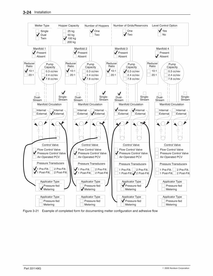
Installation3-24
Part 331149G � 2005 Nordson Corporation
Hopper Capacity
25 kg50 kg100 kg200 kg
Manifold 1
PresentAbsent
ReducerRatio
10:1
20:1
PumpCapacity
0.3 cc/rev2.4 cc/rev7.8 cc/rev
Dual-Stream
Single-Stream
Manifold Circulation
InternalExternal
Control Valve
Flow Control ValvePressure Control ValveAir-Operated PCV
InternalExternal
Applicator Type
Pressure-fedMetering
ReducerRatio
10:1
20:1
PumpCapacity
0.3 cc/rev2.4 cc/rev7.8 cc/rev
Dual-Stream
Single-Stream
Manifold Circulation
InternalExternal
Control Valve
Flow Control ValvePressure Control ValveAir-Operated PCV
InternalExternal
Applicator Type
Pressure-fedMetering
ReducerRatio
10:1
20:1
PumpCapacity
0.3 cc/rev2.4 cc/rev7.8 cc/rev
Dual-Stream
Single-Stream
Manifold Circulation
InternalExternal
Control Valve
Flow Control ValvePressure Control ValveAir-Operated PCV
InternalExternal
Applicator Type
Pressure-fedMetering
ReducerRatio
10:1
20:1
PumpCapacity
0.3 cc/rev2.4 cc/rev7.8 cc/rev
Dual-Stream
Single-Stream
Manifold Circulation
InternalExternal
Control Valve
Flow Control ValvePressure Control ValveAir-Operated PCV
InternalExternal
Applicator Type
Pressure-fedMetering
Number of Grids/Reservoirs Level Control Option
Manifold 2
PresentAbsent
Manifold 3
PresentAbsent
Manifold 4
PresentAbsent
OneTwo
YesNo
Number of Hoppers
OneTwo
Pressure Transducers
1 Pre-Filt.1 Post-Filt.
2 Pre-Filt.2 Post-Filt.
Pressure Transducers
1 Pre-Filt.1 Post-Filt.
2 Pre-Filt.2 Post-Filt.
Pressure Transducers
1 Pre-Filt.1 Post-Filt.
2 Pre-Filt.2 Post-Filt.
Pressure Transducers
1 Pre-Filt.1 Post-Filt.
2 Pre-Filt.2 Post-Filt.
Melter Type
SingleDualTwin
Applicator Type
Pressure-fedMetering
Applicator Type
Pressure-fedMetering
Applicator Type
Pressure-fedMetering
Applicator Type
Pressure-fedMetering
Figure 3-21 Example of completed form for documenting melter configuration and adhesive flow
Setup 4-1
Part 331149G� 2005 Nordson Corporation
Section 4Setup
WARNING: Allow only qualified personnel to perform the following tasks.Follow the safety instructions in this document and all other relateddocumentation.
WARNING: Allow only personnel with appropriate training and experienceto operate or service the equipment. The use of untrained or inexperiencedpersonnel to operate or service the equipment can result in injury, includingdeath, to themselves and others, and damage to the equipment.
Introduction This section provides procedures for setting up the melter control systemprior to operation and changing settings at any time. It also includesprocedures for flushing the system and adjusting a control valve inpreparation for initial operation.
Before performing any procedures in this section, complete the mechanicaland electrical installation procedures in the previous section, Installation.
Procedures for operating the melter are in the next section, Operation.
NOTE: Nordson gives you the option of two different operator interfaces:PanelMate or PanelView. Sample screens from a system with thePanelMate interface are used to illustrate the procedures in this manual, butthe PanelView screens are similar in appearance and function. If yourmelter has an operator interface other than PanelMate or PanelView,contact your Nordson representative as needed for assistance in setting upthe control system for your operation.
NOTE: If your system is equipped with an ACM, refer to the ACM manualfor additional setup and operating instructions.
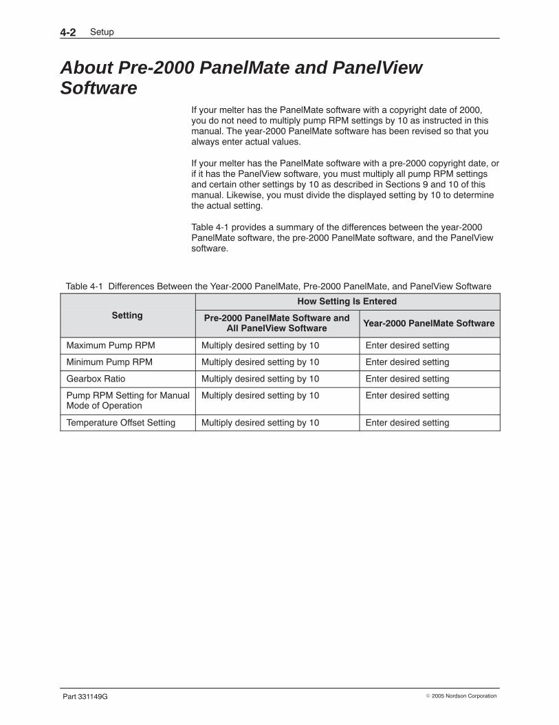
Setup4-2
Part 331149G � 2005 Nordson Corporation
About Pre-2000 PanelMate and PanelViewSoftware
If your melter has the PanelMate software with a copyright date of 2000,you do not need to multiply pump RPM settings by 10 as instructed in thismanual. The year-2000 PanelMate software has been revised so that youalways enter actual values.
If your melter has the PanelMate software with a pre-2000 copyright date, orif it has the PanelView software, you must multiply all pump RPM settingsand certain other settings by 10 as described in Sections 9 and 10 of thismanual. Likewise, you must divide the displayed setting by 10 to determinethe actual setting.
Table 4-1 provides a summary of the differences between the year-2000PanelMate software, the pre-2000 PanelMate software, and the PanelViewsoftware.
Table 4-1 Differences Between the Year-2000 PanelMate, Pre-2000 PanelMate, and PanelView Software
How Setting Is Entered
Setting Pre-2000 PanelMate Software andAll PanelView Software Year-2000 PanelMate Software
Maximum Pump RPM Multiply desired setting by 10 Enter desired setting
Minimum Pump RPM Multiply desired setting by 10 Enter desired setting
Gearbox Ratio Multiply desired setting by 10 Enter desired setting
Pump RPM Setting for ManualMode of Operation
Multiply desired setting by 10 Enter desired setting
Temperature Offset Setting Multiply desired setting by 10 Enter desired setting

Setup 4-3
Part 331149G� 2005 Nordson Corporation
This page intentionally left blank.
Setup4-4
Part 331149G � 2005 Nordson Corporation
System Navigation and Interface This part of Section 4 explains how to navigate and use the operatorinterface menus and screens.
Displaying Screens Use the navigational chart shown in Figure 4-1 to display the menu orscreen you want to use. To move from one screen to another, touch theappropriate button on the operator interface.
NOTE: If your system was set up with password protection, you must enterthe correct password to display the Main Configuration Menu or any screenthat appears on the Main Configuration Menu. Additional screens may bepassword protected in some systems. Refer to the next procedure, Enteringthe Password, for instructions on how to enter the password.
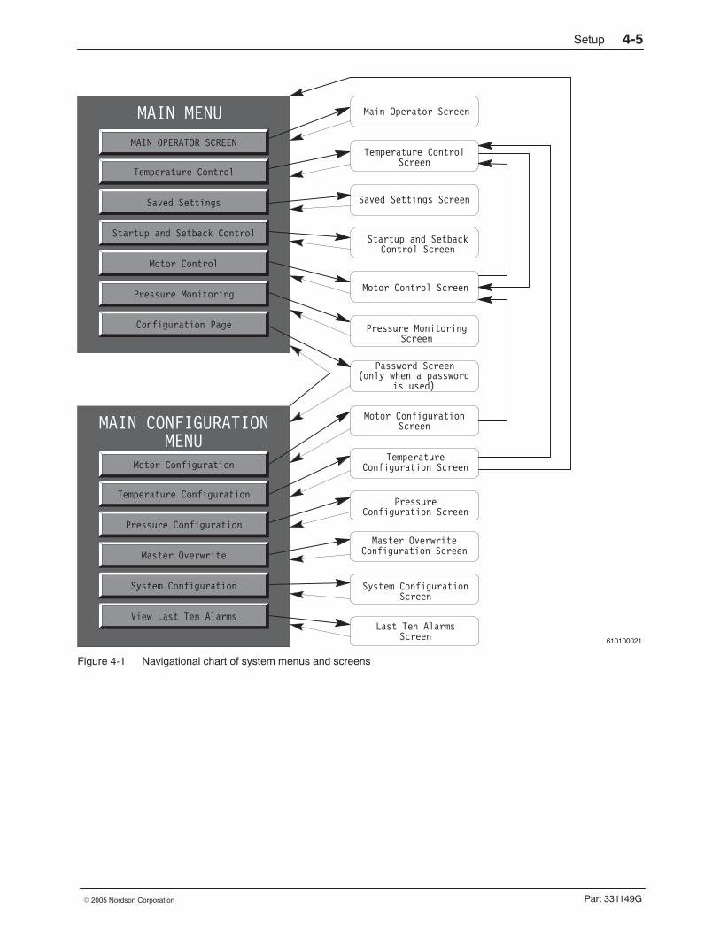
Setup 4-5
Part 331149G� 2005 Nordson Corporation
610100021
MAIN MENU
MAIN OPERATOR SCREEN
Temperature Control
Saved Settings
Startup and Setback Control
Motor Control
Pressure Monitoring
Configuration Page
MAIN CONFIGURATION
Motor Configuration
Temperature Configuration
Pressure Configuration
Master Overwrite
System Configuration
View Last Ten Alarms
MENU
Main Operator Screen
Temperature Control
Saved Settings Screen
Startup and Setback
Motor Control Screen
Pressure Monitoring
Motor Configuration
Temperature
Pressure
Master Overwrite
System Configuration
Last Ten Alarms
Screen
Control Screen
Screen
Screen
Configuration Screen
Configuration Screen
Screen
Screen
Configuration Screen
Password Screen(only when a password
(is used)
Figure 4-1 Navigational chart of system menus and screens
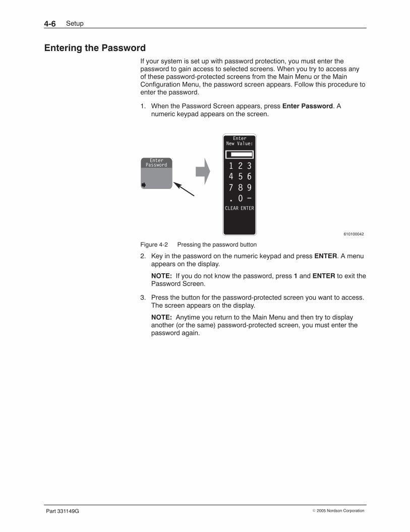
Setup4-6
Part 331149G � 2005 Nordson Corporation
Entering the Password If your system is set up with password protection, you must enter thepassword to gain access to selected screens. When you try to access anyof these password-protected screens from the Main Menu or the MainConfiguration Menu, the password screen appears. Follow this procedure toenter the password.
1. When the Password Screen appears, press Enter Password. Anumeric keypad appears on the screen.
610100042
EnterPassword
EnterNew Value:
1 2 34 5 67 8 9. 0 −
CLEAR ENTER
Figure 4-2 Pressing the password button
2. Key in the password on the numeric keypad and press ENTER. A menuappears on the display.
NOTE: If you do not know the password, press 1 and ENTER to exit thePassword Screen.
3. Press the button for the password-protected screen you want to access.The screen appears on the display.
NOTE: Anytime you return to the Main Menu and then try to displayanother (or the same) password-protected screen, you must enter thepassword again.
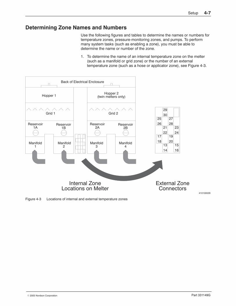
Setup 4-7
Part 331149G� 2005 Nordson Corporation
Determining Zone Names and Numbers Use the following figures and tables to determine the names or numbers fortemperature zones, pressure-monitoring zones, and pumps. To performmany system tasks (such as enabling a zone), you must be able todetermine the name or number of the zone.
1. To determine the name of an internal temperature zone on the melter(such as a manifold or grid zone) or the number of an externaltemperature zone (such as a hose or applicator zone), see Figure 4-3.
410100029
Manifold1
Manifold2
Grid 1
Hopper 1
Back of Electrical Enclosure
Reservoir1A
Reservoir1B
Hopper 2(twin melters only)
Grid 2
Reservoir2A
Reservoir2B
Manifold3
Manifold4
25
26
29
3027
28
17
18
21
2219
20
23
24
13
14
15
16
Internal ZoneLocations on Melter
External ZoneConnectors
Figure 4-3 Locations of internal and external temperature zones
Setup4-8
Part 331149G � 2005 Nordson Corporation
Determining Zone Names and Numbers (contd)
2. To determine the number of an internal temperature zone, refer toTable 4-2. On some screens, internal temperature zones are referred toby number instead of by name.
Table 4-2 Temperature Zone Numbers
Zone Name Zone No. Zone Name Zone No.
Grid 1 1 Hopper 1 7
Grid 2 2 Hopper 2 8
Reservoir 1A 3 Manifold 1 9
Reservoir 1B 4 Manifold 2 10
Reservoir 2A 5 Manifold 3 11
Reservoir 2B 6 Manifold 4 12
NOTE: All zones are shown on the operator interface, even when youhave purchased a melter that is not equipped with all zones. Systemswith a single hopper will not have a hopper 2. Some systems will nothave grid 2, reservoir 2A and 2B, and hopper 2. The total number ofmanifolds can vary from only one to as many as four.
3. If you prefer to use application-specific names or numbers for yourexternal temperature zones, use Table 4-3 to provide a cross-referencebetween the Nordson number and your own naming system.
Table 4-3 Customer-Specified Names for External Temperature Zones
Zone No. Customer-SpecifiedZone Name Zone No. Customer-Specified
Zone Name
13 23 See Note A.
14 24
15 25
16 26
17 27
18 28
19 29
20 30
21 31 See Note B.
22 32 See Note B.
NOTE A: Single-tank melters have only 10 external temperature zones.
B: On standard melters, this zone is reserved for heating the optionalbulk-fill valve.
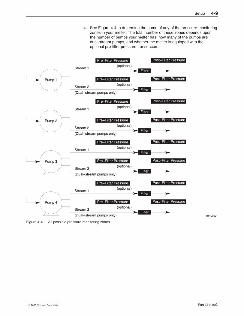
Setup 4-9
Part 331149G� 2005 Nordson Corporation
4. See Figure 4-4 to determine the name of any of the pressure-monitoringzones in your melter. The total number of these zones depends uponthe number of pumps your melter has, how many of the pumps aredual-stream pumps, and whether the melter is equipped with theoptional pre-filter pressure transducers.
410100031
Pre−Filter Pressure
Filter
Post−Filter Pressure
Stream 1(optional)
Pre−Filter Pressure
Filter
Post−Filter Pressure
Stream 2(optional)
(Dual−stream pumps only)
Pump 1
Pre−Filter Pressure
Filter
Post−Filter Pressure
Stream 1(optional)
Pre−Filter Pressure
Filter
Post−Filter Pressure
Stream 2(optional)
(Dual−stream pumps only)
Pump 2
Pre−Filter Pressure
Filter
Post−Filter Pressure
Stream 1(optional)
Pre−Filter Pressure
Filter
Post−Filter Pressure
Stream 2(optional)
(Dual−stream pumps only)
Pump 3
Pre−Filter Pressure
Filter
Post−Filter Pressure
Stream 1(optional)
Pre−Filter Pressure
Filter
Post−Filter Pressure
Stream 2(optional)
(Dual−stream pumps only)
Pump 4
Figure 4-4 All possible pressure-monitoring zones
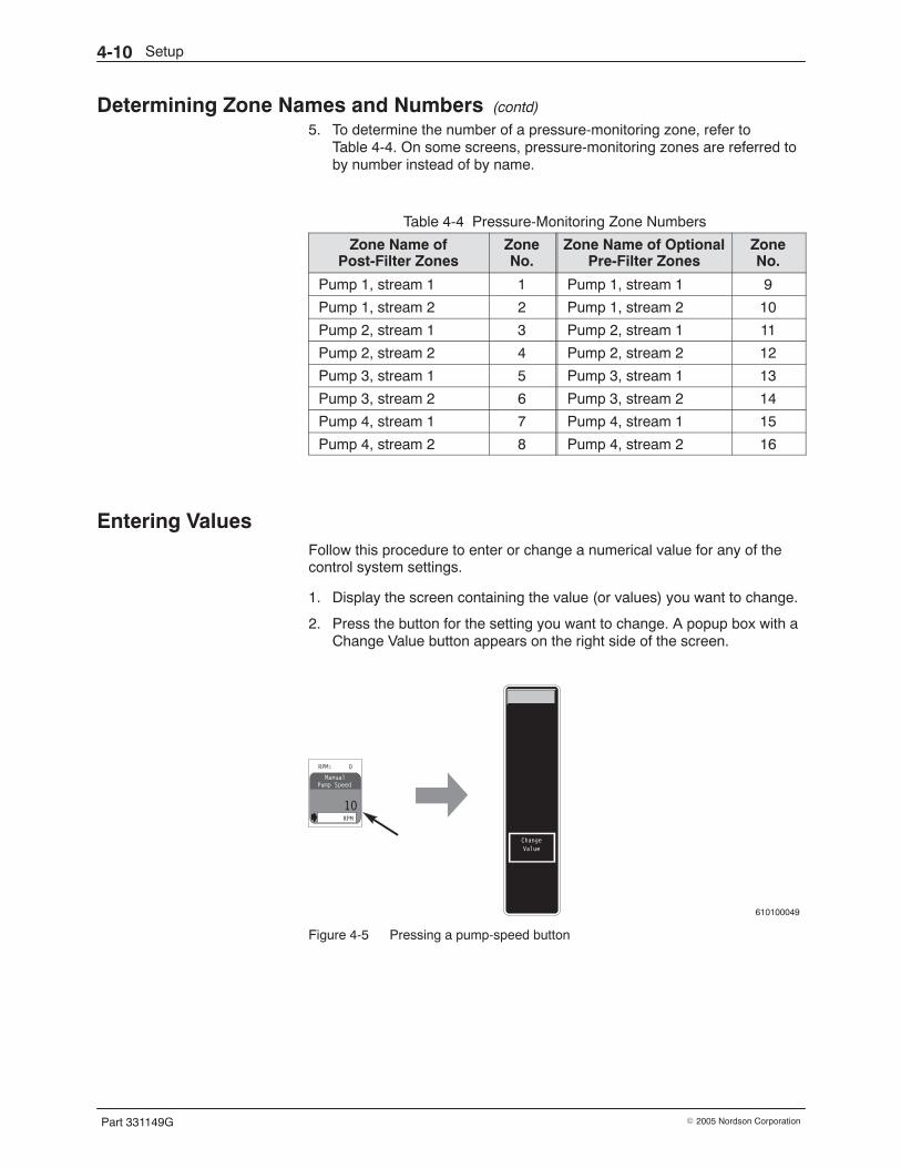
Setup4-10
Part 331149G � 2005 Nordson Corporation
Determining Zone Names and Numbers (contd)
5. To determine the number of a pressure-monitoring zone, refer toTable 4-4. On some screens, pressure-monitoring zones are referred toby number instead of by name.
Table 4-4 Pressure-Monitoring Zone Numbers
Zone Name ofPost-Filter Zones
ZoneNo.
Zone Name of OptionalPre-Filter Zones
ZoneNo.
Pump 1, stream 1 1 Pump 1, stream 1 9
Pump 1, stream 2 2 Pump 1, stream 2 10
Pump 2, stream 1 3 Pump 2, stream 1 11
Pump 2, stream 2 4 Pump 2, stream 2 12
Pump 3, stream 1 5 Pump 3, stream 1 13
Pump 3, stream 2 6 Pump 3, stream 2 14
Pump 4, stream 1 7 Pump 4, stream 1 15
Pump 4, stream 2 8 Pump 4, stream 2 16
Entering Values Follow this procedure to enter or change a numerical value for any of thecontrol system settings.
1. Display the screen containing the value (or values) you want to change.
2. Press the button for the setting you want to change. A popup box with aChange Value button appears on the right side of the screen.
610100049
Figure 4-5 Pressing a pump-speed button
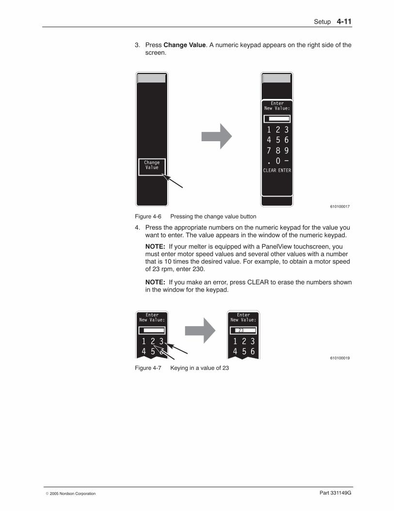
Setup 4-11
Part 331149G� 2005 Nordson Corporation
3. Press Change Value. A numeric keypad appears on the right side of thescreen.
610100017
ChangeValue
EnterNew Value:
1 2 34 5 67 8 9. 0 −
CLEAR ENTER
Figure 4-6 Pressing the change value button
4. Press the appropriate numbers on the numeric keypad for the value youwant to enter. The value appears in the window of the numeric keypad.
NOTE: If your melter is equipped with a PanelView touchscreen, youmust enter motor speed values and several other values with a numberthat is 10 times the desired value. For example, to obtain a motor speedof 23 rpm, enter 230.
NOTE: If you make an error, press CLEAR to erase the numbers shownin the window for the keypad.
610100019
EnterNew Value:
1 2 34 5 6
EnterNew Value:
1 2 34 5 6
23
Figure 4-7 Keying in a value of 23
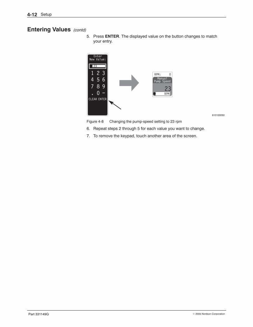
Setup4-12
Part 331149G � 2005 Nordson Corporation
Entering Values (contd)
5. Press ENTER. The displayed value on the button changes to matchyour entry.
610100050
EnterNew Value:
1 2 34 5 67 8 9. 0 −
CLEAR ENTER
Manual
23RPM
Pump Speed
RPM: 0
23
Figure 4-8 Changing the pump-speed setting to 23 rpm
6. Repeat steps 2 through 5 for each value you want to change.
7. To remove the keypad, touch another area of the screen.
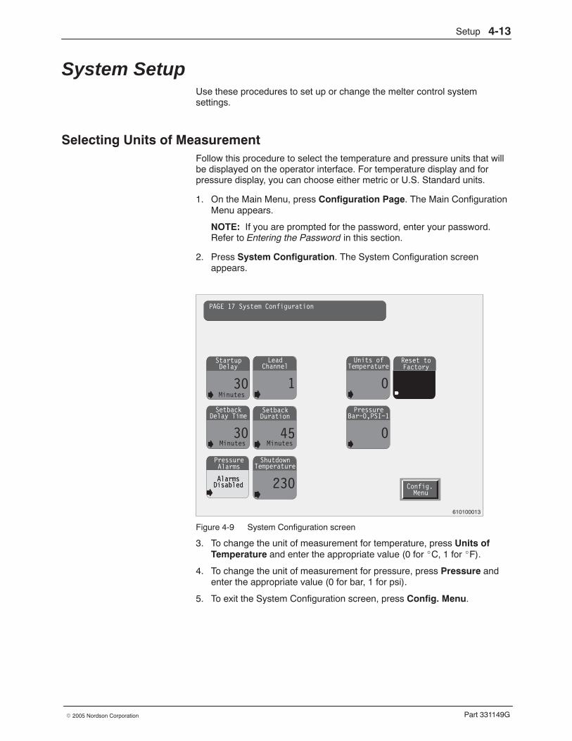
Setup 4-13
Part 331149G� 2005 Nordson Corporation
System Setup Use these procedures to set up or change the melter control systemsettings.
Selecting Units of Measurement Follow this procedure to select the temperature and pressure units that willbe displayed on the operator interface. For temperature display and forpressure display, you can choose either metric or U.S. Standard units.
1. On the Main Menu, press Configuration Page. The Main ConfigurationMenu appears.
NOTE: If you are prompted for the password, enter your password.Refer to Entering the Password in this section.
2. Press System Configuration. The System Configuration screenappears.
Startup
30
Delay
AlarmsDisabled
PressureAlarms
Lead
1
Channel
Setback
30
Delay TimeSetback
45
Duration
Units of
0
Temperature
Pressure
0
Bar−0,PSI−1
Minutes
Shutdown
230
Temperature
AlarmsDisabled
Reset toFactory
Config.Menu
PAGE 17 System Configuration
Minutes Minutes
610100013
Figure 4-9 System Configuration screen
3. To change the unit of measurement for temperature, press Units ofTemperature and enter the appropriate value (0 for �C, 1 for �F).
4. To change the unit of measurement for pressure, press Pressure andenter the appropriate value (0 for bar, 1 for psi).
5. To exit the System Configuration screen, press Config. Menu.
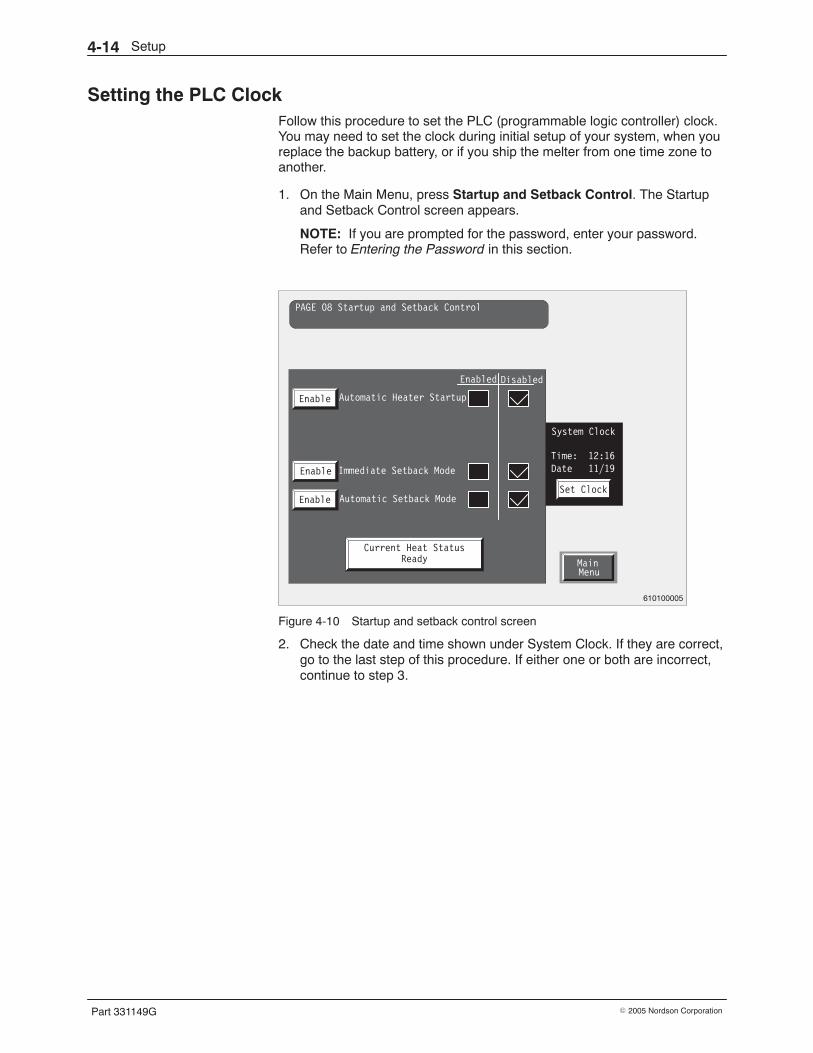
Setup4-14
Part 331149G � 2005 Nordson Corporation
Setting the PLC Clock Follow this procedure to set the PLC (programmable logic controller) clock.You may need to set the clock during initial setup of your system, when youreplace the backup battery, or if you ship the melter from one time zone toanother.
1. On the Main Menu, press Startup and Setback Control. The Startupand Setback Control screen appears.
NOTE: If you are prompted for the password, enter your password.Refer to Entering the Password in this section.
MainMenu
PAGE 08 Startup and Setback Control
Automatic Heater Startup
Enabled Disabled
Enable
Immediate Setback Mode
Automatic Setback Mode
Enable
Enable
Current Heat StatusReady
Set Clock
System Clock
Time: 12:16Date 11/19
610100005
Figure 4-10 Startup and setback control screen
2. Check the date and time shown under System Clock. If they are correct,go to the last step of this procedure. If either one or both are incorrect,continue to step 3.
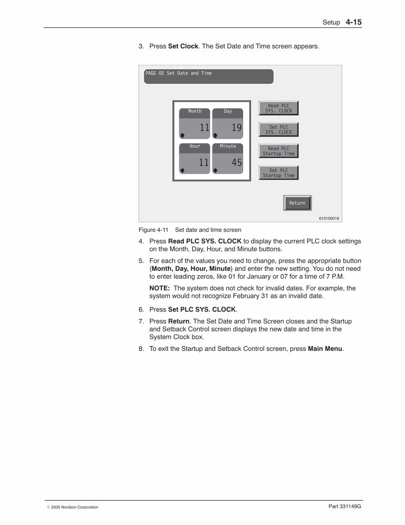
Setup 4-15
Part 331149G� 2005 Nordson Corporation
3. Press Set Clock. The Set Date and Time screen appears.
Return
PAGE 02 Set Date and Time
Month
11
Day
19
Hour
11
Minute
45
Read PLCSYS. CLOCK
Set PLCSYS. CLOCK
Read PLCStartup Time
Set PLCStartup Time
610100016
Figure 4-11 Set date and time screen
4. Press Read PLC SYS. CLOCK to display the current PLC clock settingson the Month, Day, Hour, and Minute buttons.
5. For each of the values you need to change, press the appropriate button(Month, Day, Hour, Minute) and enter the new setting. You do not needto enter leading zeros, like 01 for January or 07 for a time of 7 P.M.
NOTE: The system does not check for invalid dates. For example, thesystem would not recognize February 31 as an invalid date.
6. Press Set PLC SYS. CLOCK.
7. Press Return. The Set Date and Time Screen closes and the Startupand Setback Control screen displays the new date and time in theSystem Clock box.
8. To exit the Startup and Setback Control screen, press Main Menu.
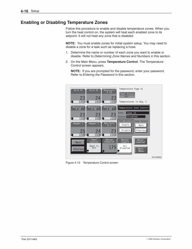
Setup4-16
Part 331149G � 2005 Nordson Corporation
Enabling or Disabling Temperature Zones Follow this procedure to enable and disable temperature zones. When youturn the heat control on, the system will heat each enabled zone to itssetpoint. It will not heat any zone that is disabled.
NOTE: You must enable zones for initial system setup. You may need todisable a zone for a task such as replacing a hose.
1. Determine the name or number of each zone you want to enable ordisable. Refer to Determining Zone Names and Numbers in this section.
2. On the Main Menu, press Temperature Control. The TemperatureControl screen appears.
NOTE: If you are prompted for the password, enter your password.Refer to Entering the Password in this section.
Heat Status
Zone:
Status:
AllDisabled
Zone 13
Disabled
Temperature Zone Control
MasterEnable
MotorControl
MainMenu
Zone Action
Enable
Disable
Next
Previous
Zone Select
Next
23100
Temperature Page #1
Off
Temperatures in Deg. C
Heat isOn
HeatControlHeat isOff
HeatControl
Grid #1 Grid #2
24100
Manifold
23100
# 1Hopper 2
24100
Hopper 1
25100
Reservoir
23100
# 1BReservoir
23100
# 2AReservoir
23100
# 2B
Reservoir
23100
# 1A
Master
175
Setpoint
Zone Action
Enable
Disable
PreviousPrevious
610100003
Figure 4-12 Temperature Control screen
Setup 4-17
Part 331149G� 2005 Nordson Corporation
3. Use the following table to determine which steps you should follow next.The table directs you to the fastest way to enable zones based uponyour objective. It also shows which steps to follow next if you want todisable one or more zones.
Objective Steps to Follow
To enable all zones or most zones.(This is the usual objective duringinitial setup.)
Complete step 4 and (if theyapply) steps 5 and 6.
To enable one zone or several zones Complete steps 7 through 10.
To disable one or more zones Complete steps 7 through 10.
To check the status of one or morezones
Complete steps 7 through 10
4. Press Master Enable and then press Enable All Zones in the box thatpops up on the screen. The Master Enable status changes from “AllDisabled” or “Partially Enabled” to “All Enabled” as all disabled zonesare enabled.
NOTE: If one or more of the external zones are not used on yourmelter, you will see the Alarm screen with the message “Open RTD.”There will be one open-RTD alarm for each unconnected external zone.The system automatically disables all zones on which open-RTD alarmsoccur.
5. If the Alarm screen appears on the panel, press Acknowledge AllAlarms. This action removes the Alarm screen.
6. If you want to disable any of the connected zones, continue to the nextstep. If you do not want to disable any zones, skip to step 10.
7. Press Next or Previous under Zone Select to display the appropriatezone.
8. Press Enable or Disable. The status of the zone changes to “ZoneEnabled” or “Zone Disabled” to match your choice.
9. Repeat steps 7 and 8 for each zone to be enabled or disabled.
10. To exit the Temperature Control screen, press Main Menu or MotorControl.
11. Record the status of each zone (enabled or disabled). The tables at theend of this section provide a place to record all your settings.
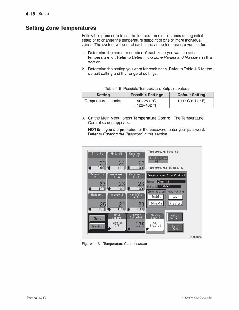
Setup4-18
Part 331149G � 2005 Nordson Corporation
Setting Zone Temperatures Follow this procedure to set the temperatures of all zones during initialsetup or to change the temperature setpoint of one or more individualzones. The system will control each zone at the temperature you set for it.
1. Determine the name or number of each zone you want to set atemperature for. Refer to Determining Zone Names and Numbers in thissection.
2. Determine the setting you want for each zone. Refer to Table 4-5 for thedefault setting and the range of settings.
Table 4-5 Possible Temperature Setpoint Values
Setting Possible Settings Default Setting
Temperature setpoint 50−250 �C (122−482 �F)
100 �C (212 �F)
3. On the Main Menu, press Temperature Control. The TemperatureControl screen appears.
NOTE: If you are prompted for the password, enter your password.Refer to Entering the Password in this section.
Heat Status
Zone:
Status:
AllEnabled
Zone 13
Enabled
Temperature Zone Control
MasterEnable
MotorControl
MainMenu
Zone Action
Enable
Disable
Next
Previous
Zone Select
Next
23100
Temperature Page #1
Off
Temperatures in Deg. C
Heat isOn
HeatControlHeat isOff
HeatControl
Grid #1 Grid #2
24100
Manifold
23100
# 1Hopper 2
24100
Hopper 1
25100
Reservoir
23100
# 1BReservoir
23100
# 2AReservoir
23100
# 2B
Reservoir
23100
# 1A
Master
175
Setpoint
Zone Action
Enable
Disable
Previous
610100043
Figure 4-13 Temperature Control screen
Setup 4-19
Part 331149G� 2005 Nordson Corporation
4. Use the following table to determine which steps of this procedure youshould follow next. The table directs you to the fastest way to set zonetemperatures based upon your objective.
Objective Next Step
To perform initial setup and enter thesame setpoint for all or most zones
Go to step 5.
To perform initial setup and enterdifferent setpoints for all or mostzones
Go to step 7.
To change one or several setpoints(either during initial setup or at a latertime)
Go to step 7.
To check one or more setpoints Go to step 7.
5. Press Master Setpoint and enter the desired temperature. Thetemperature you enter becomes the setpoint for all temperature zones,including any disabled zones.
NOTE: You can enter any (valid) setting on a master overwrite buttonexcept the one shown on the button. For example, if a value of 175 iscurrently shown on the button and that happens to be the setting youwant to enter, you must first enter some other value (such as 174 or176) and then change it to 175 by repeating the process. Or you maydecide that a setting as close as possible to 175 (such as 174 or 176) isacceptable.
6. If the master settings you entered in the previous step are the settingsyou want for all zones, go to step 12. If you want to change the setpointfor one or more zones, continue to the next step.
7. Locate the appropriate temperature-zone button for the zone you wantto set up or modify. If necessary, press Next or Previous in the lowerleft corner of the screen to display the group of temperature-zonebuttons that include the desired zone.
8. Press the appropriate temperature-zone button and enter the desiredtemperature setpoint.
9. Press Next or Previous under Zone Select to check the status of thezone. The Current Zone # changes to show the zone you have selected.
10. Check the Status of the zone. If the Status is “Disabled” and you want toenable the zone, press Enable to change the status to “Enabled.”
11. Repeat steps 7 through 10 for each temperature zone you want to setup or modify.
12. To exit the Temperature Control screen, press Main Menu or MotorControl.
13. Record your settings. The tables at the end of this section provide aplace to record all your settings.
Setup4-20
Part 331149G � 2005 Nordson Corporation
Entering a Temperature Offset Follow this procedure if you want to enter a temperature offset for one ormore temperature zones in your system.
Explanation
In some temperature zones, the temperature of the adhesive (or, in somecases, of the air) may rise or fall significantly between the point wheretemperature is sensed and the point where the material is applied. Thetemperature offset feature gives you a way to compensate for thisdifference. For example, if want an application temperature of 200 �C (392�F) and you are losing 5 �C (9 �F) between the point of sensing and thepoint of application, you can enter a minus 5 �C (minus 9 �F) for the offset.The system subtracts this number of degrees from the temperaturefeedback from the sensor, causing the zone to be heated approximately5 �C (9 �F) higher than the setpoint temperature of 200 �C (392 �F). As aresult, the air will exit at the application point close to the desired applicationtemperature of 200 �C (392 �F).
Procedure 1. Determine the name or number of each air temperature zone you want
to enter a temperature offset for. Refer to Determining Zone Names andNumbers in this section.
2. Determine the setting you want for each zone. Refer to Table 4-6 for thedefault setting and the range of settings.
Table 4-6 Possible Temperature Offset Settings
Setting Possible Settings Default Setting
Temperature offset -9.9 to 9.9 �C (-9.9 to 9.9 �F)
0 �C (0 �F)
3. On the Main Menu, press Configuration Page. The Main ConfigurationMenu appears.
NOTE: If you are prompted for the password, enter your password.Refer to Entering the Password in this section.

Setup 4-21
Part 331149G� 2005 Nordson Corporation
4. Press Temperature Configuration. The Temperature Configurationscreen appears.
Gain
600
ProportionalGain
10
DerivativeGain
98
IntegralOffset
0
Setback
50
ValueLow Fault
10
DeltaHigh Fault
10
DeltaWarning
3
Delta
Config.Menu
Enable
Disable
TempControl
MainMenu
Current Zone #: TZone 14
PreviousZone
NextZone
Temperatures in Deg. C
Zone Sequential StartupStatus: Follow lead Zone
Follow Lead
Stand Alone
Zone ActivationStatus: Zone Enabled
+/−deg.
610100010
Figure 4-14 Temperature Configuration screen
5. Press Previous Zone or Next Zone to select the zone you want to set.
6. Press Offset and enter the offset value. To have the system subtractfrom the sensor feedback for the zone, enter a negative number. Tohave the system add to the sensor feedback for the zone, enter apositive number.
NOTE: If your melter is equipped with a PanelView touchscreen, enteran offset value that is 10 times the desired value. For example, if youwant a temperature offset of 5.5 degrees, enter 55.
7. Repeat steps 5 and 6 for each zone that you want to enter an offset for.
8. To exit the Temperature Configuration screen, press one of thefollowing: Main Menu, Temp. Control, or Config. Menu.
9. Record your settings. The tables at the end of this section provide aplace to record all your settings.
Setup4-22
Part 331149G � 2005 Nordson Corporation
Setting Up Sequential Startup Follow this procedure to set up the sequential startup feature for yoursystem.
Explanation
Sequential startup gives you a way to prevent char and associatedproblems that may occur when some zones reach their setpoints quicklyand then wait for the slower zones to reach theirs. The feature works byallowing you to use the current temperature of a zone that heats slowly(such as the hopper or manifold) as the setpoint of rapidly heating zones(such as applicators and hoses). With this change, the fast-heating zonesheat up at essentially the same rate as the selected slow-heating zone.
To set up the sequential startup feature, you specify a lead temperaturezone for all other zones to follow. During startup, the actual temperature ofthe lead zone is used as the setpoint for the follower zones until thetemperature of the lead zone is approaching its setpoint (or, to be precise,until it rises above the setpoint minus the warning band setting). Then allzones heat up separately to the setpoints you have entered for them.
In addition, anytime the temperature of a following zone reaches atemperature equal to its setpoint minus the warning band setting, thesystem removes this zone from sequential startup and allows the zone tocontinue to its setpoint independently.
Procedure 1. Determine the number of the lead heating zone and the numbers of the
following zones. Refer to Determining Zone Names and Numbers in thissection.
NOTE: Select as the lead zone the zone that takes the longest to reachits temperature setpoint. In most systems, a hopper zone is the last tofully heat up.
2. On the Main Menu, press Configuration Page. The Main ConfigurationMenu appears.
NOTE: If you are prompted for the password, enter your password.Refer to Entering the Password in this section.
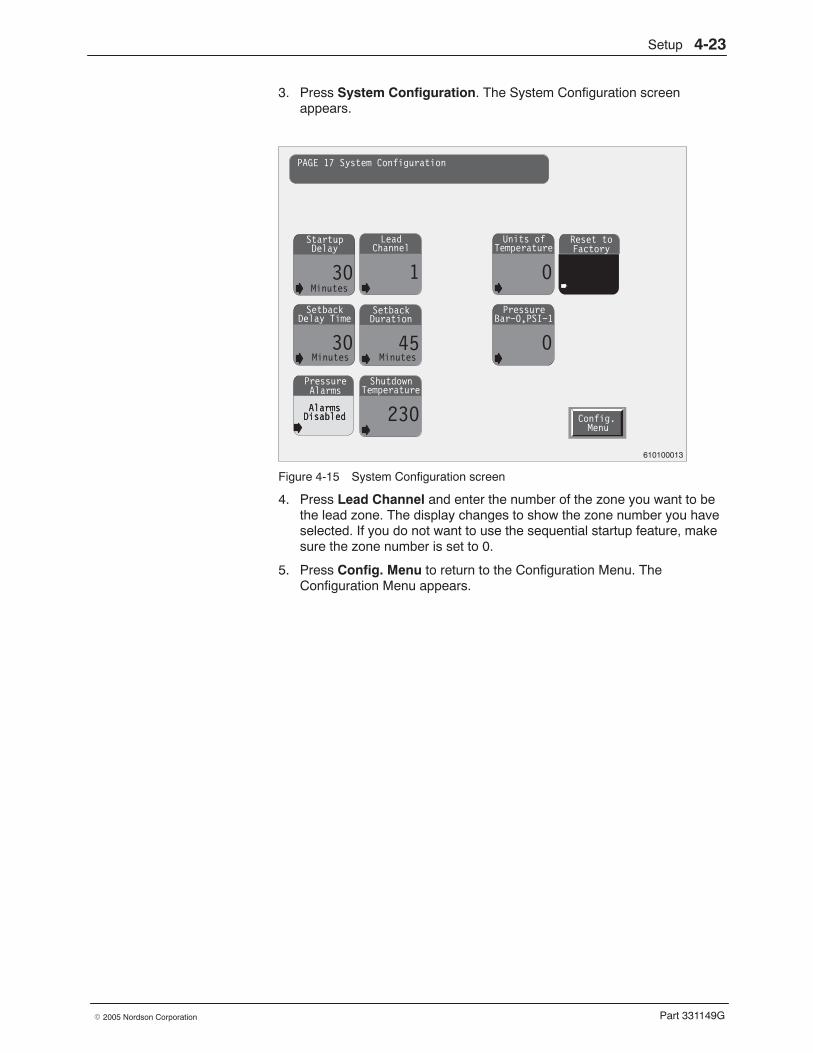
Setup 4-23
Part 331149G� 2005 Nordson Corporation
3. Press System Configuration. The System Configuration screenappears.
Startup
30
Delay
AlarmsDisabled
PressureAlarms
Lead
1
Channel
Setback
30
Delay TimeSetback
45
Duration
Units of
0
Temperature
Pressure
0
Bar−0,PSI−1
Minutes
Shutdown
230
Temperature
AlarmsDisabled
Reset toFactory
Config.Menu
PAGE 17 System Configuration
Minutes Minutes
610100013
Figure 4-15 System Configuration screen
4. Press Lead Channel and enter the number of the zone you want to bethe lead zone. The display changes to show the zone number you haveselected. If you do not want to use the sequential startup feature, makesure the zone number is set to 0.
5. Press Config. Menu to return to the Configuration Menu. TheConfiguration Menu appears.
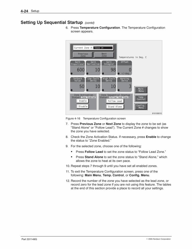
Setup4-24
Part 331149G � 2005 Nordson Corporation
Setting Up Sequential Startup (contd)
6. Press Temperature Configuration. The Temperature Configurationscreen appears.
Gain
600
ProportionalGain
10
DerivativeGain
98
IntegralOffset
0
Setback
50
ValueLow Fault
10
DeltaHigh Fault
10
DeltaWarning
3
Delta
Config.Menu
Enable
Disable
TempControl
MainMenu
Current Zone #: TZone 14
PreviousZone
NextZone
Temperatures in Deg. C
Zone Sequential StartupStatus: Follow lead Zone
Follow Lead
Stand Alone
Zone ActivationStatus: Zone Enabled
+/−deg.
610100010
Figure 4-16 Temperature Configuration screen
7. Press Previous Zone or Next Zone to display the zone to be set (as“Stand Alone” or “Follow Lead”). The Current Zone # changes to showthe zone you have selected.
8. Check the Zone Activation Status. If necessary, press Enable to changethe status to “Zone Enabled.”
9. For the selected zone, choose one of the following:
� Press Follow Lead to set the zone status to “Follow Lead Zone.”
� Press Stand Alone to set the zone status to “Stand Alone,” whichallows the zone to heat at its own pace.
10. Repeat steps 7 through 9 until you have set all enabled zones.
11. To exit the Temperature Configuration screen, press one of thefollowing: Main Menu, Temp. Control, or Config. Menu.
12. Record the number of the zone you have selected as the lead zone, orrecord zero for the lead zone if you are not using this feature. The tablesat the end of this section provide a place to record all your settings.
Setup 4-25
Part 331149G� 2005 Nordson Corporation
Setting Up Startup Delay Follow this procedure to set up the startup delay feature.
Explanation
The startup delay feature gives you a way to ensure that all of the adhesivein the system is sufficiently melted before the pumps can be started. If thestartup delay feature is not used, the system enters the ready state whenthe temperatures of all zones are close enough to their setpoints that a lowtemperature warning will not occur. In some systems this does not give theadhesive in the reservoir enough time to melt. To prevent this situation, youcan specify an additional period of time (in minutes) for the adhesive tocontinue melting. The system will not enter the ready state until the timeperiod has elapsed, thus preventing the pumps from being started beforethe adhesive is sufficiently melted.
Procedure 1. Determine the setting you want for the startup delay. Refer to Table 4-7
for the default setting and the range of settings.
Table 4-7 Possible Startup Delay Settings
Setting Possible Settings Default Setting
Startup delay 0−120 minutes 20 minutes
2. On the Main Menu, press Configuration Page. The Main ConfigurationMenu appears.
NOTE: If you are prompted for the password, enter your password.Refer to Entering the Password in this section.
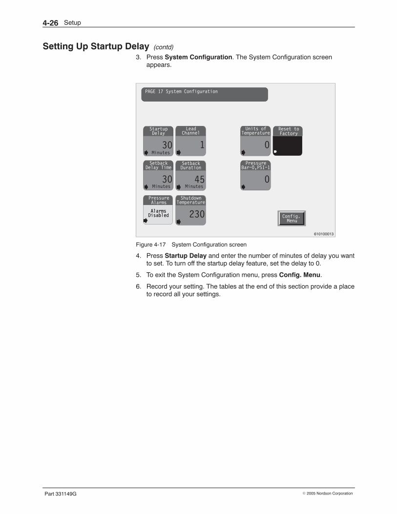
Setup4-26
Part 331149G � 2005 Nordson Corporation
Setting Up Startup Delay (contd)
3. Press System Configuration. The System Configuration screenappears.
Startup
30
Delay
AlarmsDisabled
PressureAlarms
Lead
1
Channel
Setback
30
Delay TimeSetback
45
Duration
Units of
0
Temperature
Pressure
0
Bar−0,PSI−1
Minutes
Shutdown
230
Temperature
AlarmsDisabled
Reset toFactory
Config.Menu
PAGE 17 System Configuration
Minutes Minutes
610100013
Figure 4-17 System Configuration screen
4. Press Startup Delay and enter the number of minutes of delay you wantto set. To turn off the startup delay feature, set the delay to 0.
5. To exit the System Configuration menu, press Config. Menu.
6. Record your setting. The tables at the end of this section provide a placeto record all your settings.
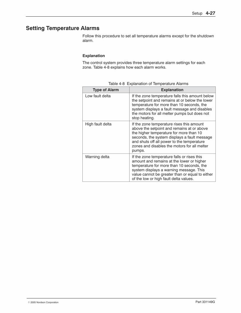
Setup 4-27
Part 331149G� 2005 Nordson Corporation
Setting Temperature Alarms Follow this procedure to set all temperature alarms except for the shutdownalarm.
Explanation
The control system provides three temperature alarm settings for eachzone. Table 4-8 explains how each alarm works.
Table 4-8 Explanation of Temperature Alarms
Type of Alarm Explanation
Low fault delta If the zone temperature falls this amount belowthe setpoint and remains at or below the lowertemperature for more than 10 seconds, thesystem displays a fault message and disablesthe motors for all melter pumps but does notstop heating.
High fault delta If the zone temperature rises this amountabove the setpoint and remains at or abovethe higher temperature for more than 10seconds, the system displays a fault messageand shuts off all power to the temperaturezones and disables the motors for all melterpumps.
Warning delta If the zone temperature falls or rises thisamount and remains at the lower or highertemperature for more than 10 seconds, thesystem displays a warning message. Thisvalue cannot be greater than or equal to eitherof the low or high fault delta values.
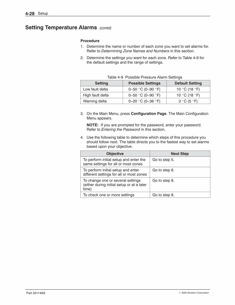
Setup4-28
Part 331149G � 2005 Nordson Corporation
Setting Temperature Alarms (contd)
Procedure 1. Determine the name or number of each zone you want to set alarms for.
Refer to Determining Zone Names and Numbers in this section.
2. Determine the settings you want for each zone. Refer to Table 4-9 forthe default settings and the range of settings.
Table 4-9 Possible Pressure Alarm Settings
Setting Possible Settings Default Setting
Low fault delta 0−50 �C (0−90 �F) 10 �C (18 �F)
High fault delta 0−50 �C (0−90 �F) 10 �C (18 �F)
Warning delta 0−20 �C (0−36 �F) 3 �C (5 �F)
3. On the Main Menu, press Configuration Page. The Main ConfigurationMenu appears.
NOTE: If you are prompted for the password, enter your password.Refer to Entering the Password in this section.
4. Use the following table to determine which steps of this procedure youshould follow next. The table directs you to the fastest way to set alarmsbased upon your objective.
Objective Next Step
To perform initial setup and enter thesame settings for all or most zones
Go to step 5.
To perform initial setup and enterdifferent settings for all or most zones
Go to step 8.
To change one or several settings(either during initial setup or at a latertime)
Go to step 8.
To check one or more settings Go to step 8.
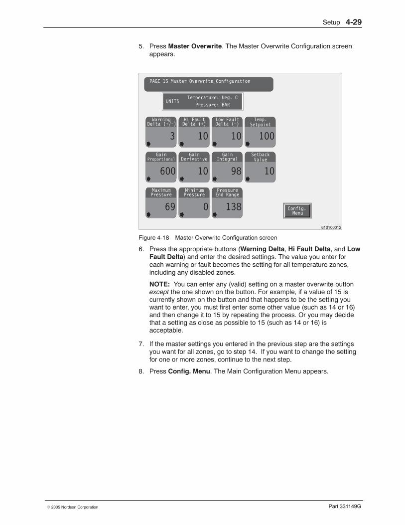
Setup 4-29
Part 331149G� 2005 Nordson Corporation
5. Press Master Overwrite. The Master Overwrite Configuration screenappears.
Gain
600
ProportionalGain
10
DerivativeGain
98
IntegralSetback
10
Maximum
69
PressureMinimum
0
PressurePressure
138
End Range
Warning
3
Delta (+/−)Hi Fault
10
Delta (+)Low Fault
10
Delta (−)Temp.
100
Config.Menu
PAGE 15 Master Overwrite Configuration
UNITSTemperature: Deg. C
Pressure: BAR
Setpoint
Value
610100012
Figure 4-18 Master Overwrite Configuration screen
6. Press the appropriate buttons (Warning Delta, Hi Fault Delta, and LowFault Delta) and enter the desired settings. The value you enter foreach warning or fault becomes the setting for all temperature zones,including any disabled zones.
NOTE: You can enter any (valid) setting on a master overwrite buttonexcept the one shown on the button. For example, if a value of 15 iscurrently shown on the button and that happens to be the setting youwant to enter, you must first enter some other value (such as 14 or 16)and then change it to 15 by repeating the process. Or you may decidethat a setting as close as possible to 15 (such as 14 or 16) isacceptable.
7. If the master settings you entered in the previous step are the settingsyou want for all zones, go to step 14. If you want to change the settingfor one or more zones, continue to the next step.
8. Press Config. Menu. The Main Configuration Menu appears.
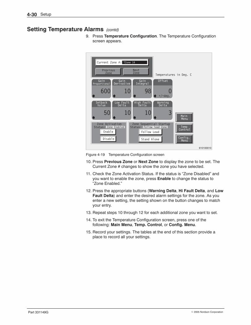
Setup4-30
Part 331149G � 2005 Nordson Corporation
Setting Temperature Alarms (contd)
9. Press Temperature Configuration. The Temperature Configurationscreen appears.
Gain
600
ProportionalGain
10
DerivativeGain
98
IntegralOffset
0
Setback
50
ValueLow Fault
10
DeltaHigh Fault
10
DeltaWarning
3
Delta
Config.Menu
Enable
Disable
TempControl
MainMenu
Current Zone #: TZone 14
PreviousZone
NextZone
Temperatures in Deg. C
Zone Sequential StartupStatus: Follow lead Zone
Follow Lead
Stand Alone
Zone ActivationStatus: Zone Enabled
+/−deg.
610100010
Figure 4-19 Temperature Configuration screen
10. Press Previous Zone or Next Zone to display the zone to be set. TheCurrent Zone # changes to show the zone you have selected.
11. Check the Zone Activation Status. If the status is “Zone Disabled” andyou want to enable the zone, press Enable to change the status to“Zone Enabled.”
12. Press the appropriate buttons (Warning Delta, Hi Fault Delta, and LowFault Delta) and enter the desired alarm settings for the zone. As youenter a new setting, the setting shown on the button changes to matchyour entry.
13. Repeat steps 10 through 12 for each additional zone you want to set.
14. To exit the Temperature Configuration screen, press one of thefollowing: Main Menu, Temp. Control, or Config. Menu.
15. Record your settings. The tables at the end of this section provide aplace to record all your settings.
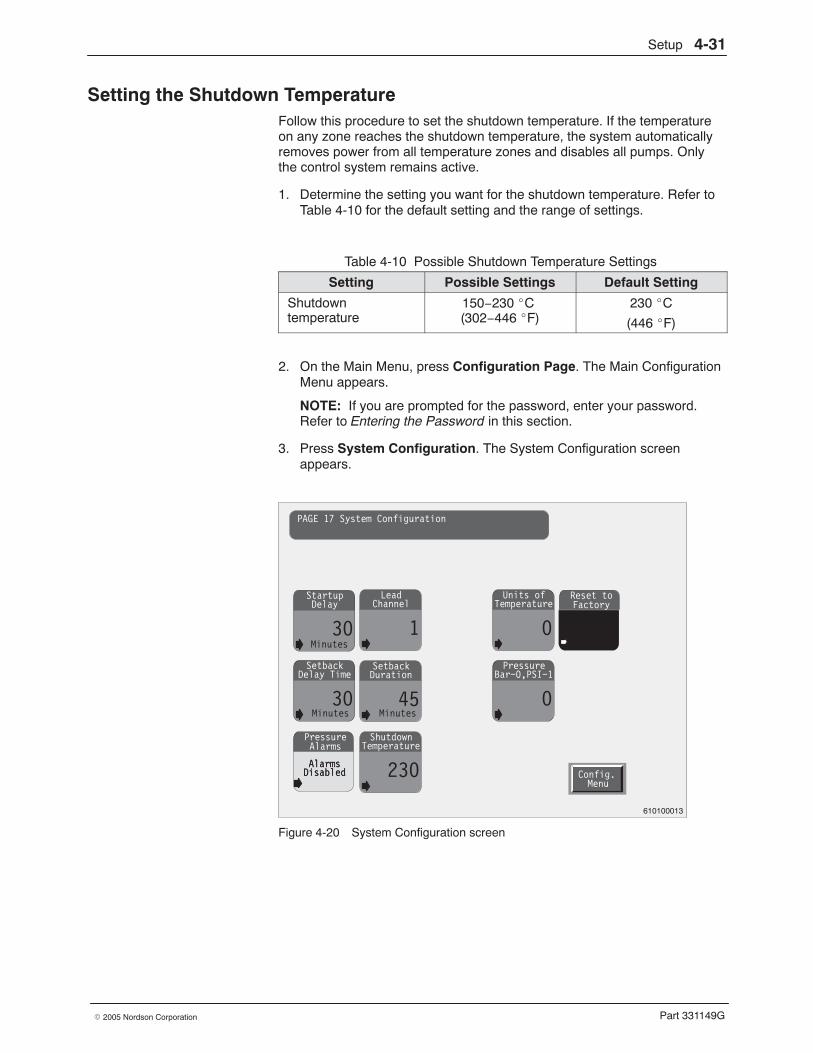
Setup 4-31
Part 331149G� 2005 Nordson Corporation
Setting the Shutdown Temperature Follow this procedure to set the shutdown temperature. If the temperatureon any zone reaches the shutdown temperature, the system automaticallyremoves power from all temperature zones and disables all pumps. Onlythe control system remains active.
1. Determine the setting you want for the shutdown temperature. Refer toTable 4-10 for the default setting and the range of settings.
Table 4-10 Possible Shutdown Temperature Settings
Setting Possible Settings Default Setting
Shutdowntemperature
150−230 �C (302−446 �F)
230 �C
(446 �F)
2. On the Main Menu, press Configuration Page. The Main ConfigurationMenu appears.
NOTE: If you are prompted for the password, enter your password.Refer to Entering the Password in this section.
3. Press System Configuration. The System Configuration screenappears.
Startup
30
Delay
AlarmsDisabled
PressureAlarms
Lead
1
Channel
Setback
30
Delay TimeSetback
45
Duration
Units of
0
Temperature
Pressure
0
Bar−0,PSI−1
Minutes
Shutdown
230
Temperature
AlarmsDisabled
Reset toFactory
Config.Menu
PAGE 17 System Configuration
Minutes Minutes
610100013
Figure 4-20 System Configuration screen
Setup4-32
Part 331149G � 2005 Nordson Corporation
Setting the Shutdown Temperature (contd)
4. Press Shutdown Temperature and enter the desired temperature. Thedisplay changes to show the temperature you entered.
5. To exit the System Configuration menu, press Config. Menu.
6. Record your setting. The tables at the end of this section provide a placeto record all your settings.
Setting Up Temperature Setback Follow this procedure to set up the temperature setback feature. Tomanually enter or exit the setback mode, refer to Entering and Exiting theSetback Mode in Section 5, Operation.
Explanation
The temperature setback feature is designed to prevent char formation andto conserve energy during breaks in production. When the system entersthe setback mode, it drops the temperature of each enabled zone by thesetback amount (the number of degrees previously entered) and then keepseach zone at the reduced temperature. Setback can be applied to all zonesor just to selected individual zones.
The system can be placed in the setback mode in two different ways: eitherthrough immediate setback or through automatic setback. Immediatesetback occurs when an operator manually places the system in thesetback mode through the Startup and Setback Control screen. Automaticsetback occurs when the pumps have remained inactive for theuser-specified amount of time and the system activates the setback mode.
The system can also exit the setback mode in different ways. When thesystem is in immediate setback, an operator can remove the system fromthe setback mode, or the system can automatically exit setback mode afterthe pumps have remained inactive for the user-specified amount of time.When the system is in automatic setback, an operator must always removethe system from the setback mode through the Startup and Setback Controlscreen.
If the system is in the setback mode when automatic startup occurs, it willautomatically exit the setback mode and return the zones to their normaloperating setpoints.
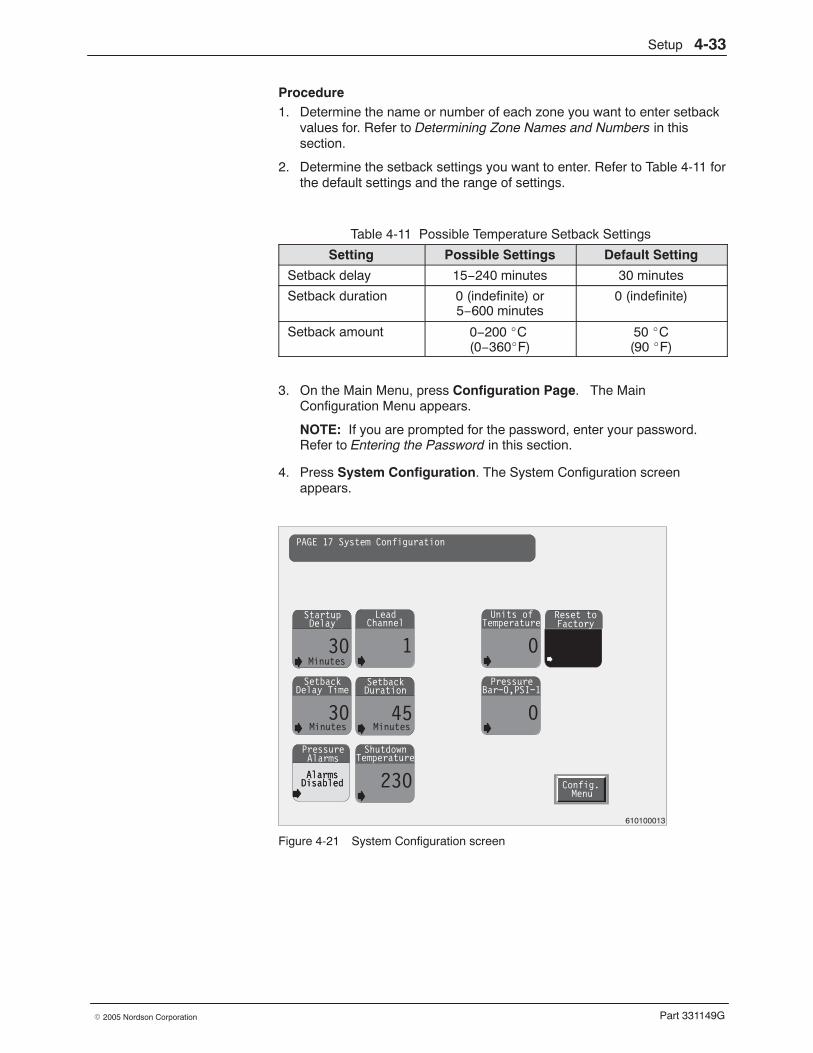
Setup 4-33
Part 331149G� 2005 Nordson Corporation
Procedure 1. Determine the name or number of each zone you want to enter setback
values for. Refer to Determining Zone Names and Numbers in thissection.
2. Determine the setback settings you want to enter. Refer to Table 4-11 forthe default settings and the range of settings.
Table 4-11 Possible Temperature Setback Settings
Setting Possible Settings Default Setting
Setback delay 15−240 minutes 30 minutes
Setback duration 0 (indefinite) or5−600 minutes
0 (indefinite)
Setback amount 0−200 �C (0−360�F)
50 �C(90 �F)
3. On the Main Menu, press Configuration Page. The MainConfiguration Menu appears.
NOTE: If you are prompted for the password, enter your password.Refer to Entering the Password in this section.
4. Press System Configuration. The System Configuration screenappears.
Startup
30Delay
AlarmsDisabled
PressureAlarms
Lead
1Channel
Setback
30Delay Time
Setback
45Duration
Units of
0Temperature
Pressure
0Bar−0,PSI−1
Minutes
Shutdown
230Temperature
AlarmsDisabled
Reset toFactory
Config.Menu
PAGE 17 System Configuration
Minutes Minutes
610100013
Figure 4-21 System Configuration screen
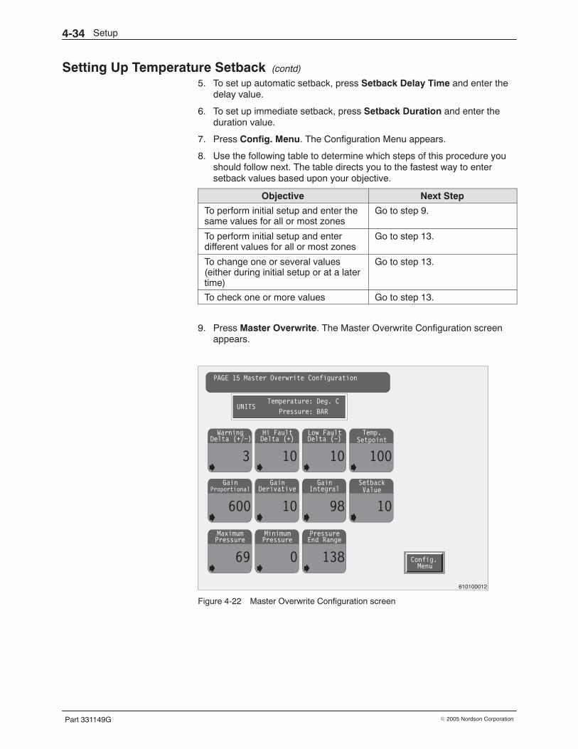
Setup4-34
Part 331149G � 2005 Nordson Corporation
Setting Up Temperature Setback (contd)
5. To set up automatic setback, press Setback Delay Time and enter thedelay value.
6. To set up immediate setback, press Setback Duration and enter theduration value.
7. Press Config. Menu. The Configuration Menu appears.
8. Use the following table to determine which steps of this procedure youshould follow next. The table directs you to the fastest way to entersetback values based upon your objective.
Objective Next Step
To perform initial setup and enter thesame values for all or most zones
Go to step 9.
To perform initial setup and enterdifferent values for all or most zones
Go to step 13.
To change one or several values(either during initial setup or at a latertime)
Go to step 13.
To check one or more values Go to step 13.
9. Press Master Overwrite. The Master Overwrite Configuration screenappears.
Gain
600
ProportionalGain
10
DerivativeGain
98
IntegralSetback
10
Maximum
69
PressureMinimum
0
PressurePressure
138
End Range
Warning
3
Delta (+/−)Hi Fault
10
Delta (+)Low Fault
10
Delta (−)Temp.
100
Config.Menu
PAGE 15 Master Overwrite Configuration
UNITSTemperature: Deg. C
Pressure: BAR
Setpoint
Value
610100012
Figure 4-22 Master Overwrite Configuration screen
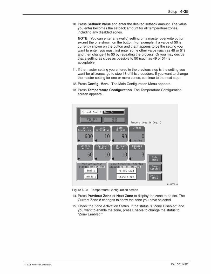
Setup 4-35
Part 331149G� 2005 Nordson Corporation
10. Press Setback Value and enter the desired setback amount. The valueyou enter becomes the setback amount for all temperature zones,including any disabled zones.
NOTE: You can enter any (valid) setting on a master overwrite buttonexcept the one shown on the button. For example, if a value of 50 iscurrently shown on the button and that happens to be the setting youwant to enter, you must first enter some other value (such as 49 or 51)and then change it to 50 by repeating the process. Or you may decidethat a setting as close as possible to 50 (such as 49 or 51) isacceptable.
11. If the master setting you entered in the previous step is the setting youwant for all zones, go to step 18 of this procedure. If you want to changethe master setting for one or more zones, continue to the next step.
12. Press Config. Menu. The Main Configuration Menu appears.
13. Press Temperature Configuration. The Temperature Configurationscreen appears.
Gain
600
ProportionalGain
10
DerivativeGain
98
IntegralOffset
0
Setback
50
ValueLow Fault
10
DeltaHigh Fault
10
DeltaWarning
3
Delta
Config.Menu
Enable
Disable
TempControl
MainMenu
Current Zone #: TZone 14
PreviousZone
NextZone
Temperatures in Deg. C
Zone Sequential StartupStatus: Follow lead Zone
Follow Lead
Stand Alone
Zone ActivationStatus: Zone Enabled
+/−deg.
610100010
Figure 4-23 Temperature Configuration screen
14. Press Previous Zone or Next Zone to display the zone to be set. TheCurrent Zone # changes to show the zone you have selected.
15. Check the Zone Activation Status. If the status is “Zone Disabled” andyou want to enable the zone, press Enable to change the status to“Zone Enabled.”
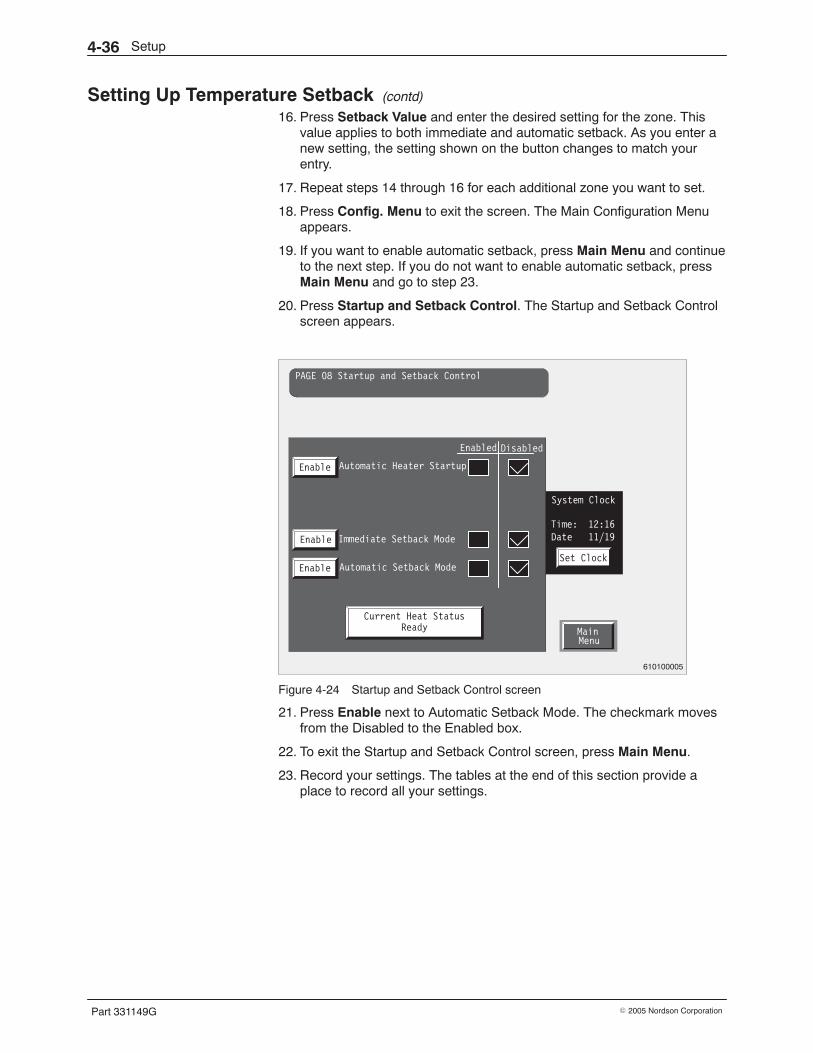
Setup4-36
Part 331149G � 2005 Nordson Corporation
Setting Up Temperature Setback (contd)
16. Press Setback Value and enter the desired setting for the zone. Thisvalue applies to both immediate and automatic setback. As you enter anew setting, the setting shown on the button changes to match yourentry.
17. Repeat steps 14 through 16 for each additional zone you want to set.
18. Press Config. Menu to exit the screen. The Main Configuration Menuappears.
19. If you want to enable automatic setback, press Main Menu and continueto the next step. If you do not want to enable automatic setback, pressMain Menu and go to step 23.
20. Press Startup and Setback Control. The Startup and Setback Controlscreen appears.
MainMenu
PAGE 08 Startup and Setback Control
Automatic Heater Startup
Enabled Disabled
Enable
Immediate Setback Mode
Automatic Setback Mode
Enable
Enable
Current Heat StatusReady
Set Clock
System Clock
Time: 12:16Date 11/19
610100005
Figure 4-24 Startup and Setback Control screen
21. Press Enable next to Automatic Setback Mode. The checkmark movesfrom the Disabled to the Enabled box.
22. To exit the Startup and Setback Control screen, press Main Menu.
23. Record your settings. The tables at the end of this section provide aplace to record all your settings.
Setup 4-37
Part 331149G� 2005 Nordson Corporation
Setting PID Values Follow this procedure to set PID (proportional/integral/derivative) values.
Explanation
The melter is shipped with default PID values that will work well for most, ifnot all, temperature zones. Nordson recommends that you do not changethe PID values unless you encounter a temperature control problem for oneor more zones. If you have experience in PID tuning, you can use thisprocedure to change the values.
The following procedure assumes that you already know the PID values youwant to enter.
Procedure 1. Determine the name or number of each zone you want to enter new PID
values for. Refer to Determining Zone Names and Numbers in thissection.
2. Determine the settings you want for each zone.
3. On the Main Menu, press Configuration Page. The Main ConfigurationMenu appears.
NOTE: If you are prompted for the password, enter your password.Refer to Entering the Password in this section.
4. Use the following table to determine which steps of this procedure youshould follow next. The table directs you to the fastest way to set PIDvalues based upon your objective.
Objective Next Step
To perform initial setup and enter thesame PID values for all or most zones
Go to step 5.
To perform initial setup and enterdifferent PID settings for all or mostzones
Go to step 8.
To change one or several settings(either during initial setup or at a latertime)
Go to step 8.
To check one or more settings Go to step 8.
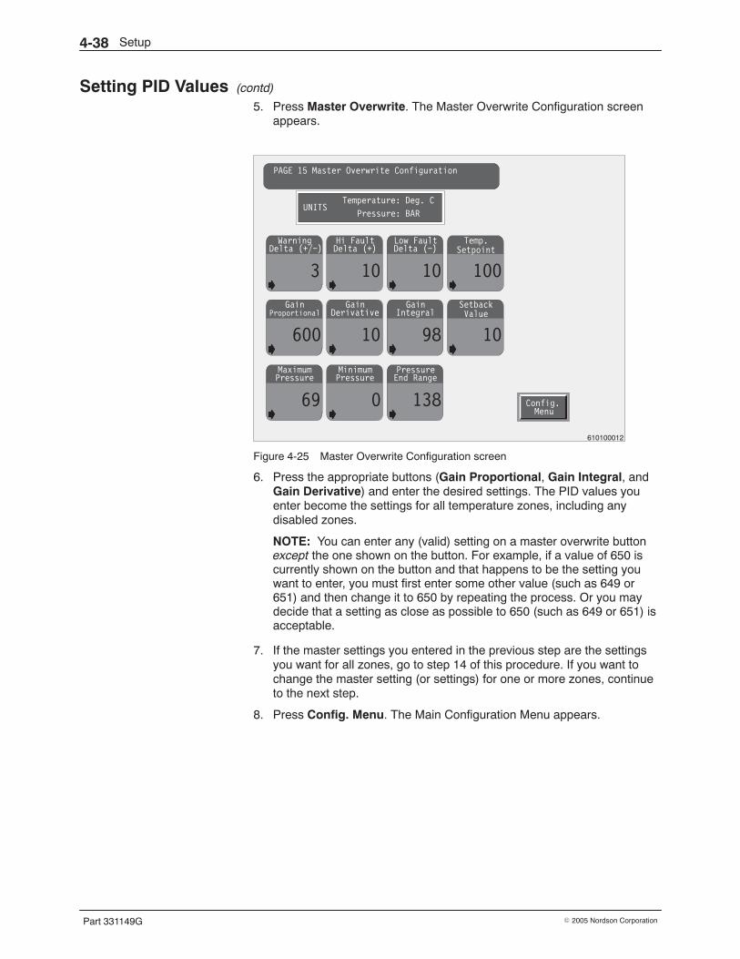
Setup4-38
Part 331149G � 2005 Nordson Corporation
Setting PID Values (contd)
5. Press Master Overwrite. The Master Overwrite Configuration screenappears.
Gain
600
ProportionalGain
10
DerivativeGain
98
IntegralSetback
10
Maximum
69
PressureMinimum
0
PressurePressure
138
End Range
Warning
3
Delta (+/−)Hi Fault
10
Delta (+)Low Fault
10
Delta (−)Temp.
100
Config.Menu
PAGE 15 Master Overwrite Configuration
UNITSTemperature: Deg. C
Pressure: BAR
Setpoint
Value
610100012
Figure 4-25 Master Overwrite Configuration screen
6. Press the appropriate buttons (Gain Proportional, Gain Integral, andGain Derivative) and enter the desired settings. The PID values youenter become the settings for all temperature zones, including anydisabled zones.
NOTE: You can enter any (valid) setting on a master overwrite buttonexcept the one shown on the button. For example, if a value of 650 iscurrently shown on the button and that happens to be the setting youwant to enter, you must first enter some other value (such as 649 or651) and then change it to 650 by repeating the process. Or you maydecide that a setting as close as possible to 650 (such as 649 or 651) isacceptable.
7. If the master settings you entered in the previous step are the settingsyou want for all zones, go to step 14 of this procedure. If you want tochange the master setting (or settings) for one or more zones, continueto the next step.
8. Press Config. Menu. The Main Configuration Menu appears.
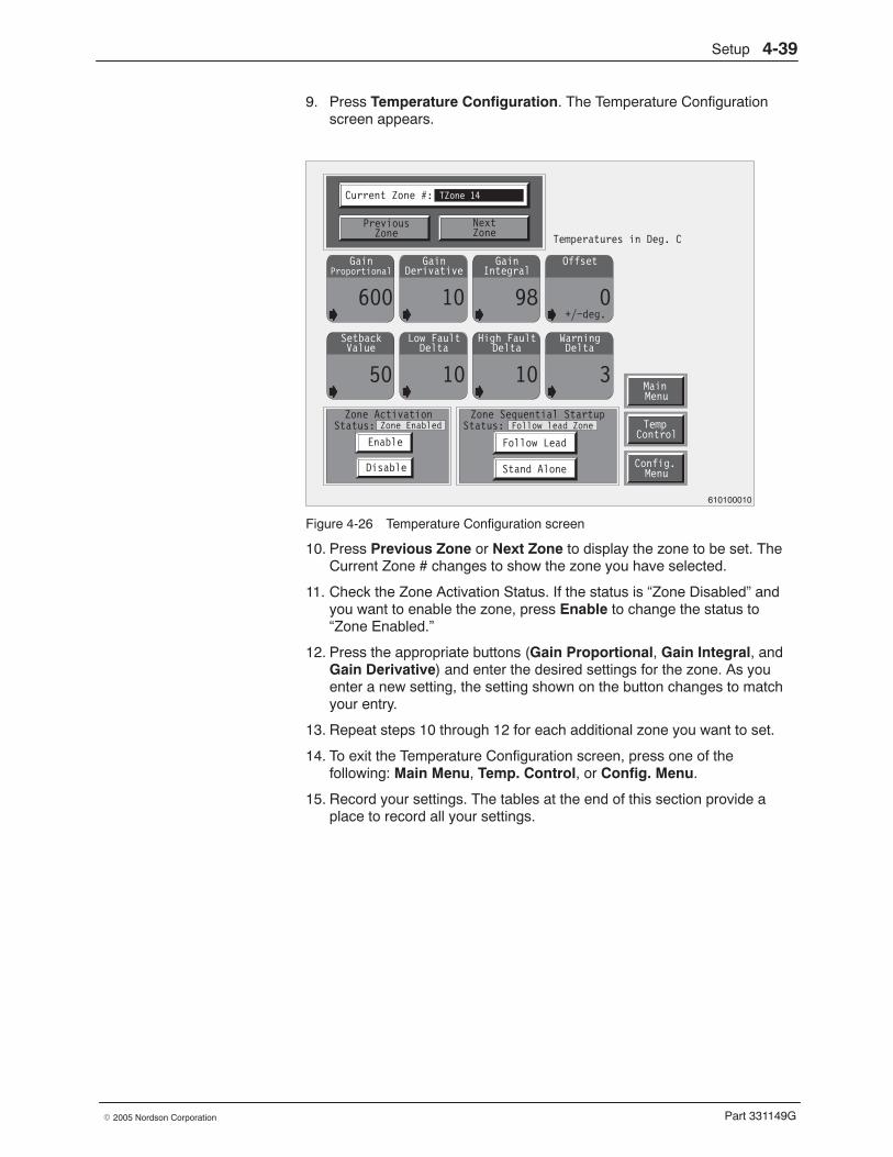
Setup 4-39
Part 331149G� 2005 Nordson Corporation
9. Press Temperature Configuration. The Temperature Configurationscreen appears.
Gain
600
ProportionalGain
10
DerivativeGain
98
IntegralOffset
0
Setback
50
ValueLow Fault
10
DeltaHigh Fault
10
DeltaWarning
3
Delta
Config.Menu
Enable
Disable
TempControl
MainMenu
Current Zone #: TZone 14
PreviousZone
NextZone
Temperatures in Deg. C
Zone Sequential StartupStatus: Follow lead Zone
Follow Lead
Stand Alone
Zone ActivationStatus: Zone Enabled
+/−deg.
610100010
Figure 4-26 Temperature Configuration screen
10. Press Previous Zone or Next Zone to display the zone to be set. TheCurrent Zone # changes to show the zone you have selected.
11. Check the Zone Activation Status. If the status is “Zone Disabled” andyou want to enable the zone, press Enable to change the status to“Zone Enabled.”
12. Press the appropriate buttons (Gain Proportional, Gain Integral, andGain Derivative) and enter the desired settings for the zone. As youenter a new setting, the setting shown on the button changes to matchyour entry.
13. Repeat steps 10 through 12 for each additional zone you want to set.
14. To exit the Temperature Configuration screen, press one of thefollowing: Main Menu, Temp. Control, or Config. Menu.
15. Record your settings. The tables at the end of this section provide aplace to record all your settings.
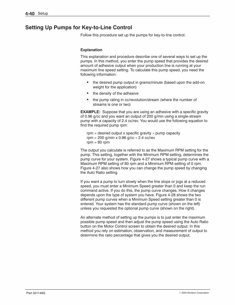
Setup4-40
Part 331149G � 2005 Nordson Corporation
Setting Up Pumps for Key-to-Line Control Follow this procedure set up the pumps for key-to-line control.
Explanation
This explanation and procedure describe one of several ways to set up thepumps. In this method, you enter the pump speed that provides the desiredamount of adhesive output when your production line is running at yourmaximum line speed setting. To calculate this pump speed, you need thefollowing information:
� the desired pump output in grams/minute (based upon the add-onweight for the application)
� the density of the adhesive
� the pump rating in cc/revolution/stream (where the number ofstreams is one or two)
EXAMPLE: Suppose that you are using an adhesive with a specific gravityof 0.96 g/cc and you want an output of 200 g/min using a single-streampump with a capacity of 2.4 cc/rev. You would use the following equation tofind the required pump rpm:
rpm = desired output x specific gravity ÷ pump capacityrpm = 200 g/min x 0.96 g/cc ÷ 2.4 cc/revrpm = 80 rpm
The output you calculate is referred to as the Maximum RPM setting for thepump. This setting, together with the Minimum RPM setting, determines thepump curve for your system. Figure 4-27 shows a typical pump curve with aMaximum RPM setting of 80 rpm and a Minimum RPM setting of 0 rpm.Figure 4-27 also shows how you can change the pump speed by changingthe Auto Ratio setting.
If you want a pump to turn slowly when the line stops or jogs at a reducedspeed, you must enter a Minimum Speed greater than 0 and keep the runcommand active. If you do this, the pump curve changes. How it changesdepends upon the type of system you have. Figure 4-28 shows the twodifferent pump curves when a Minimum Speed setting greater than 0 isentered. Your system has the standard pump curve (shown on the left)unless you requested the optional pump curve (shown on the right).
An alternate method of setting up the pumps is to just enter the maximumpossible pump speed and then adjust the pump speed using the Auto Ratiobutton on the Motor Control screen to obtain the desired output. In thismethod you rely on estimation, observation, and measurement of output todetermine the ratio percentage that gives you the desired output.
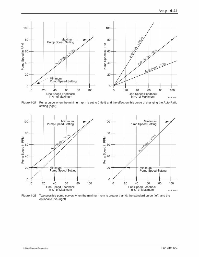
Setup 4-41
Part 331149G� 2005 Nordson Corporation
610104001
100
80
60
40
20
0
Pum
p S
peed
in R
PM
100806040200Line Speed Feedback
in % of Maximum
100
80
60
40
20
0
Pum
p S
peed
in R
PM
100806040200Line Speed Feedback
in % of Maximum
MinimumPump Speed Setting
MaximumPump Speed Setting
Figure 4-27 Pump curve when the minimum rpm is set to 0 (left) and the effect on this curve of changing the Auto Ratiosetting (right)
610104002
100
80
60
40
20
0
Pum
p S
peed
in R
PM
100806040200Line Speed Feedback
in % of Maximum
100
80
60
40
20
0
Pum
p S
peed
in R
PM
100806040200Line Speed Feedback
in % of Maximum
MinimumPump Speed Setting
MaximumPump Speed Setting
MinimumPump Speed Setting
MaximumPump Speed Setting
Figure 4-28 Two possible pump curves when the minimum rpm is greater than 0: the standard curve (left) and theoptional curve (right)
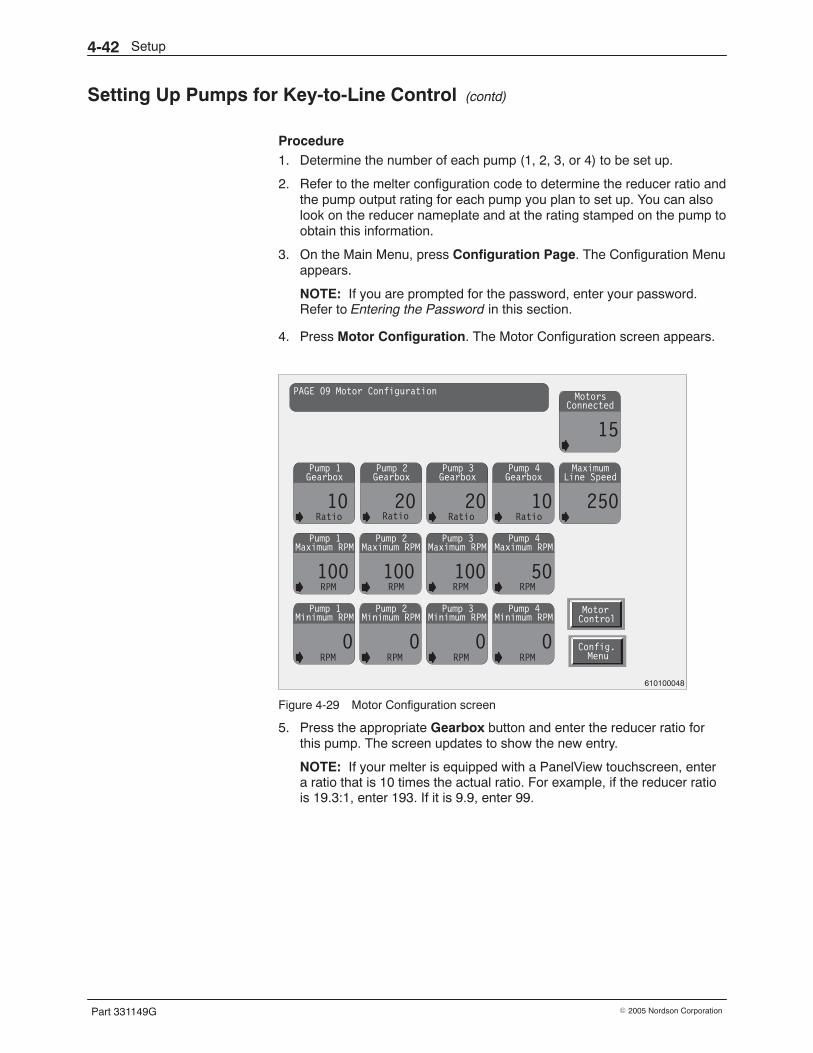
Setup4-42
Part 331149G � 2005 Nordson Corporation
Setting Up Pumps for Key-to-Line Control (contd)
Procedure 1. Determine the number of each pump (1, 2, 3, or 4) to be set up.
2. Refer to the melter configuration code to determine the reducer ratio andthe pump output rating for each pump you plan to set up. You can alsolook on the reducer nameplate and at the rating stamped on the pump toobtain this information.
3. On the Main Menu, press Configuration Page. The Configuration Menuappears.
NOTE: If you are prompted for the password, enter your password.Refer to Entering the Password in this section.
4. Press Motor Configuration. The Motor Configuration screen appears.
Pump 1
10
GearboxPump 3
20
GearboxPump 4
10
GearboxMaximum
250
Line Speed
Motors
15
Connected
Pump 1
100
Maximum RPMPump 2
100
Maximum RPMPump 3
100
Maximum RPMPump 4
50
Maximum RPM
Pump 1
0
Minimum RPMPump 2
0
Minimum RPMPump 3
0
Minimum RPMPump 4
0
Minimum RPMMotorControl
Config.Menu
PAGE 09 Motor Configuration
Ratio Ratio Ratio
RPM RPM RPM RPM
RPM RPM RPM RPM
Pump 2
20
Gearbox
Ratio
610100048
Figure 4-29 Motor Configuration screen
5. Press the appropriate Gearbox button and enter the reducer ratio forthis pump. The screen updates to show the new entry.
NOTE: If your melter is equipped with a PanelView touchscreen, entera ratio that is 10 times the actual ratio. For example, if the reducer ratiois 19.3:1, enter 193. If it is 9.9, enter 99.
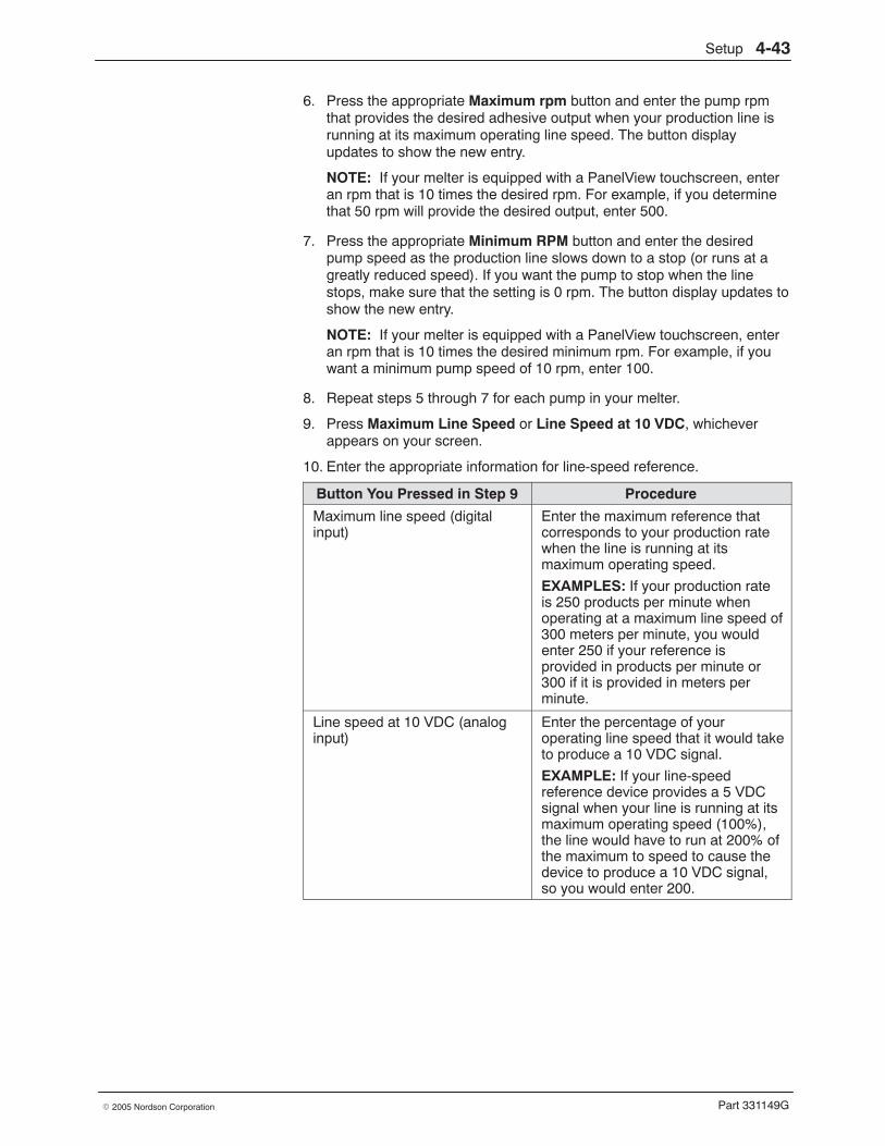
Setup 4-43
Part 331149G� 2005 Nordson Corporation
6. Press the appropriate Maximum rpm button and enter the pump rpmthat provides the desired adhesive output when your production line isrunning at its maximum operating line speed. The button displayupdates to show the new entry.
NOTE: If your melter is equipped with a PanelView touchscreen, enteran rpm that is 10 times the desired rpm. For example, if you determinethat 50 rpm will provide the desired output, enter 500.
7. Press the appropriate Minimum RPM button and enter the desiredpump speed as the production line slows down to a stop (or runs at agreatly reduced speed). If you want the pump to stop when the linestops, make sure that the setting is 0 rpm. The button display updates toshow the new entry.
NOTE: If your melter is equipped with a PanelView touchscreen, enteran rpm that is 10 times the desired minimum rpm. For example, if youwant a minimum pump speed of 10 rpm, enter 100.
8. Repeat steps 5 through 7 for each pump in your melter.
9. Press Maximum Line Speed or Line Speed at 10 VDC, whicheverappears on your screen.
10. Enter the appropriate information for line-speed reference.
Button You Pressed in Step 9 Procedure
Maximum line speed (digitalinput)
Enter the maximum reference thatcorresponds to your production ratewhen the line is running at itsmaximum operating speed.
EXAMPLES: If your production rateis 250 products per minute whenoperating at a maximum line speed of300 meters per minute, you wouldenter 250 if your reference isprovided in products per minute or300 if it is provided in meters perminute.
Line speed at 10 VDC (analoginput)
Enter the percentage of youroperating line speed that it would taketo produce a 10 VDC signal.
EXAMPLE: If your line-speedreference device provides a 5 VDCsignal when your line is running at itsmaximum operating speed (100%),the line would have to run at 200% ofthe maximum to speed to cause thedevice to produce a 10 VDC signal,so you would enter 200.
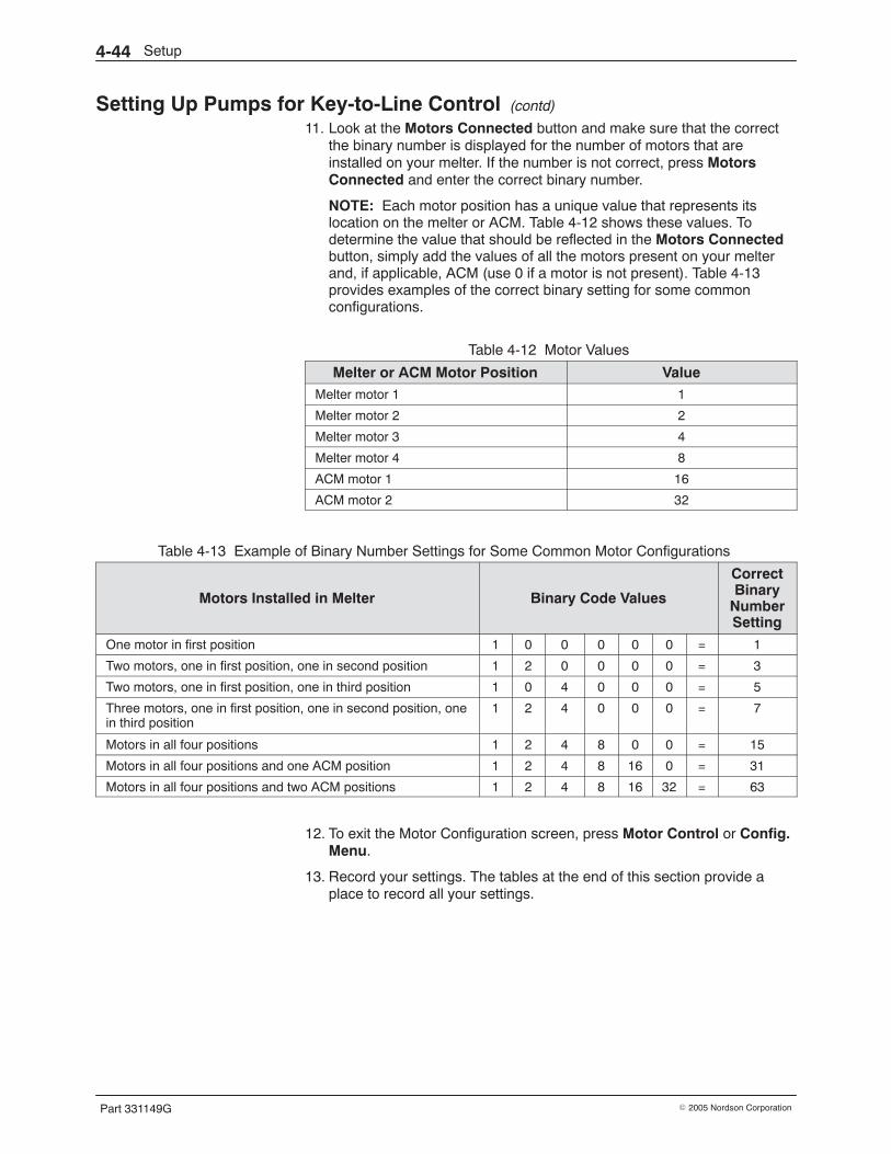
Setup4-44
Part 331149G � 2005 Nordson Corporation
Setting Up Pumps for Key-to-Line Control (contd)
11. Look at the Motors Connected button and make sure that the correctthe binary number is displayed for the number of motors that areinstalled on your melter. If the number is not correct, press MotorsConnected and enter the correct binary number.
NOTE: Each motor position has a unique value that represents itslocation on the melter or ACM. Table 4-12 shows these values. Todetermine the value that should be reflected in the Motors Connectedbutton, simply add the values of all the motors present on your melterand, if applicable, ACM (use 0 if a motor is not present). Table 4-13provides examples of the correct binary setting for some commonconfigurations.
Table 4-12 Motor Values
Melter or ACM Motor Position ValueMelter motor 1 1
Melter motor 2 2
Melter motor 3 4
Melter motor 4 8
ACM motor 1 16
ACM motor 2 32
Table 4-13 Example of Binary Number Settings for Some Common Motor Configurations
Motors Installed in Melter Binary Code Values
CorrectBinary
NumberSetting
One motor in first position 1 0 0 0 0 0 = 1
Two motors, one in first position, one in second position 1 2 0 0 0 0 = 3
Two motors, one in first position, one in third position 1 0 4 0 0 0 = 5
Three motors, one in first position, one in second position, onein third position
1 2 4 0 0 0 = 7
Motors in all four positions 1 2 4 8 0 0 = 15
Motors in all four positions and one ACM position 1 2 4 8 16 0 = 31
Motors in all four positions and two ACM positions 1 2 4 8 16 32 = 63
12. To exit the Motor Configuration screen, press Motor Control or Config.Menu.
13. Record your settings. The tables at the end of this section provide aplace to record all your settings.
Setup 4-45
Part 331149G� 2005 Nordson Corporation
Setting the Pump Pressure If your system was factory-configured for pump pressure PID control, theMelter Motor Control screen will look like the one shown in Figure 4-30.Note that for this particular system configuration the Auto Ratio Line andActual RPM value boxes for pump 3 have been changed to Auto Press SP(setpoint) and Actual Press (pressure), respectively. When pump 3 isoperating in the manual mode, its actual RPM will only be displayed abovethe Manual Pump Speed RPM setting.
Pump pressure PID control is required if the adhesive output to a meteringpump must be at a particular pressure regardless of flow. One of the ATSmelter pumps will be dedicated to supplying such a metering pump withadhesive—follow this procedure to set the pressure for that pump.
Explanation
When in the automatic mode, the ATS melter pump dedicated to supplying ametering pump at a particular pressure (hereafter referred to as pump x)operates in a closed-loop pressure-feedback mode, which means it will notfollow the line-speed reference signal. The pressure transducer thatprovides the pressure feedback is located on the metering pump to which isadhesive is being supplied and is factory-configured for each individual ATSmelter system.
When pump x is running in the closed-loop pressure-feedback mode, thecontrol system will generate alarms to warn the operator if the pressure istoo low. When the motor is at 100% of rated speed for 2 minutes, a warningappears on the Last 10 Alarms screen. If this warning is not acknowledgedwithin 10 minutes, all melter motors and any auxiliary equipment will shutdown. The warning text is as follows:
ATS Motor 1 PID LaggingATS Motor 2 PID LaggingATS Motor 3 PID LaggingATS Motor 4 PID Lagging
If necessary, the pump pressure PID settings can be adjusted. However,these settings are not accessible from the operator touchscreen—anychanges to the pump pressure PID values must be made while online to thePLC.
When in the manual mode, pump x uses the manual mode rpm setting, thusoperating like the other melter pumps.
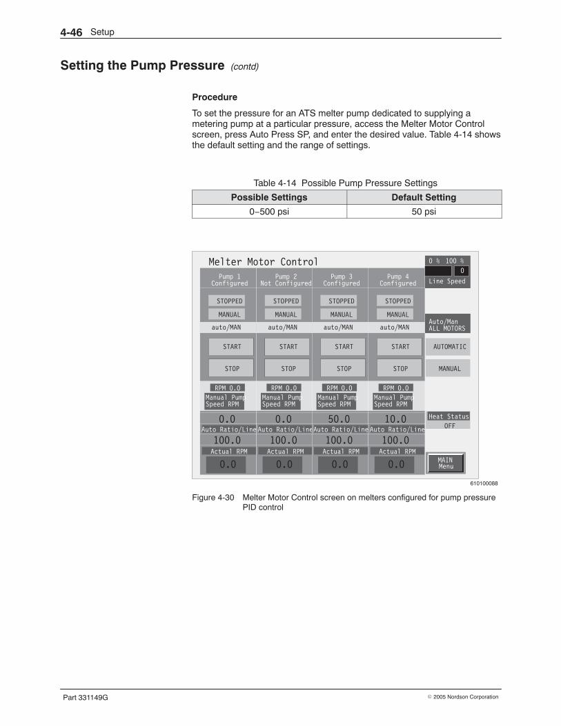
Setup4-46
Part 331149G � 2005 Nordson Corporation
Setting the Pump Pressure (contd)
Procedure
To set the pressure for an ATS melter pump dedicated to supplying ametering pump at a particular pressure, access the Melter Motor Controlscreen, press Auto Press SP, and enter the desired value. Table 4-14 showsthe default setting and the range of settings.
Table 4-14 Possible Pump Pressure Settings
Possible Settings Default Setting
0−500 psi 50 psi
MAINMenu
Melter Motor ControlPump 1
Configured
STOPPED
MANUAL
auto/MAN
START
STOP
RPM 0.0
Manual PumpSpeed RPM
0.0Auto Ratio/Line
Actual RPM
100.0
0.0
Pump 2Not Configured
STOPPED
MANUAL
auto/MAN
START
STOP
RPM 0.0
Manual PumpSpeed RPM
0.0Auto Ratio/Line
Actual RPM
100.0
0.0
Pump 3Configured
STOPPED
MANUAL
auto/MAN
START
STOP
RPM 0.0
Manual PumpSpeed RPM
50.0Auto Ratio/Line
Actual RPM
100.0
0.0
Pump 4Configured
STOPPED
MANUAL
auto/MAN
START
STOP
RPM 0.0
Manual PumpSpeed RPM
10.0Auto Ratio/Line
Actual RPM
100.0
0.0
AUTOMATIC
MANUAL
Auto/ManALL MOTORS
Line Speed
0
0 % 100 %
Heat Status
OFF
610100088
Figure 4-30 Melter Motor Control screen on melters configured for pump pressurePID control
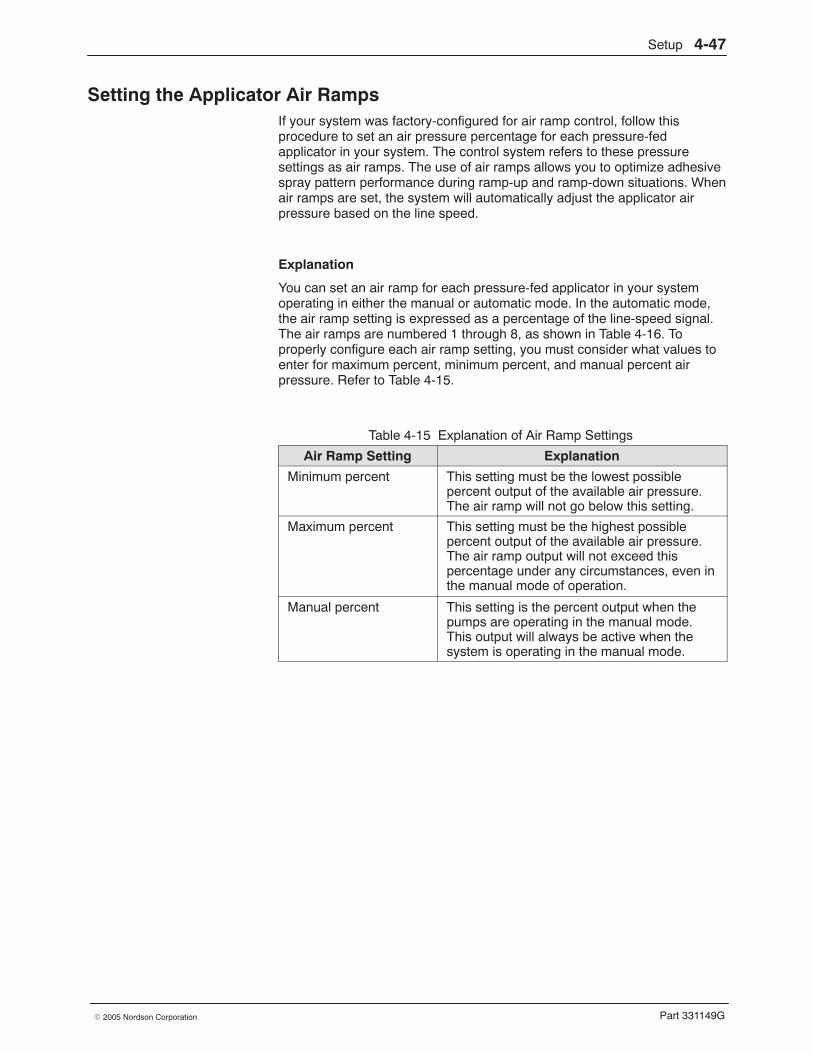
Setup 4-47
Part 331149G� 2005 Nordson Corporation
Setting the Applicator Air Ramps If your system was factory-configured for air ramp control, follow thisprocedure to set an air pressure percentage for each pressure-fedapplicator in your system. The control system refers to these pressuresettings as air ramps. The use of air ramps allows you to optimize adhesivespray pattern performance during ramp-up and ramp-down situations. Whenair ramps are set, the system will automatically adjust the applicator airpressure based on the line speed.
Explanation
You can set an air ramp for each pressure-fed applicator in your systemoperating in either the manual or automatic mode. In the automatic mode,the air ramp setting is expressed as a percentage of the line-speed signal.The air ramps are numbered 1 through 8, as shown in Table 4-16. Toproperly configure each air ramp setting, you must consider what values toenter for maximum percent, minimum percent, and manual percent airpressure. Refer to Table 4-15.
Table 4-15 Explanation of Air Ramp Settings
Air Ramp Setting Explanation
Minimum percent This setting must be the lowest possiblepercent output of the available air pressure.The air ramp will not go below this setting.
Maximum percent This setting must be the highest possiblepercent output of the available air pressure.The air ramp output will not exceed thispercentage under any circumstances, even inthe manual mode of operation.
Manual percent This setting is the percent output when thepumps are operating in the manual mode.This output will always be active when thesystem is operating in the manual mode.
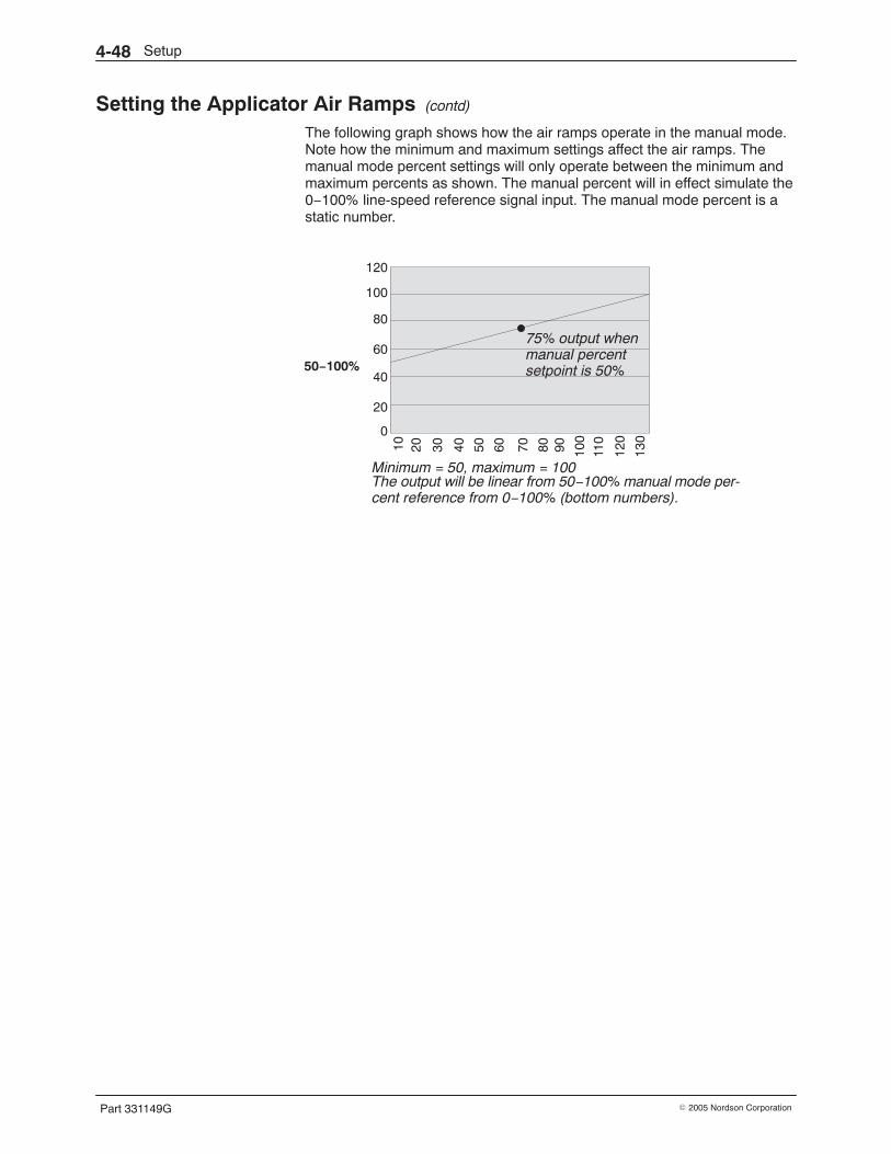
Setup4-48
Part 331149G � 2005 Nordson Corporation
Setting the Applicator Air Ramps (contd)
The following graph shows how the air ramps operate in the manual mode.Note how the minimum and maximum settings affect the air ramps. Themanual mode percent settings will only operate between the minimum andmaximum percents as shown. The manual percent will in effect simulate the0−100% line-speed reference signal input. The manual mode percent is astatic number.
120
100
80
60
40
20
0
10 20 30 40 50 60 70 80 90 100
110
120
130
Minimum = 50, maximum = 100
50−100%
The output will be linear from 50−100% manual mode per-cent reference from 0−100% (bottom numbers).
75% output whenmanual percentsetpoint is 50%
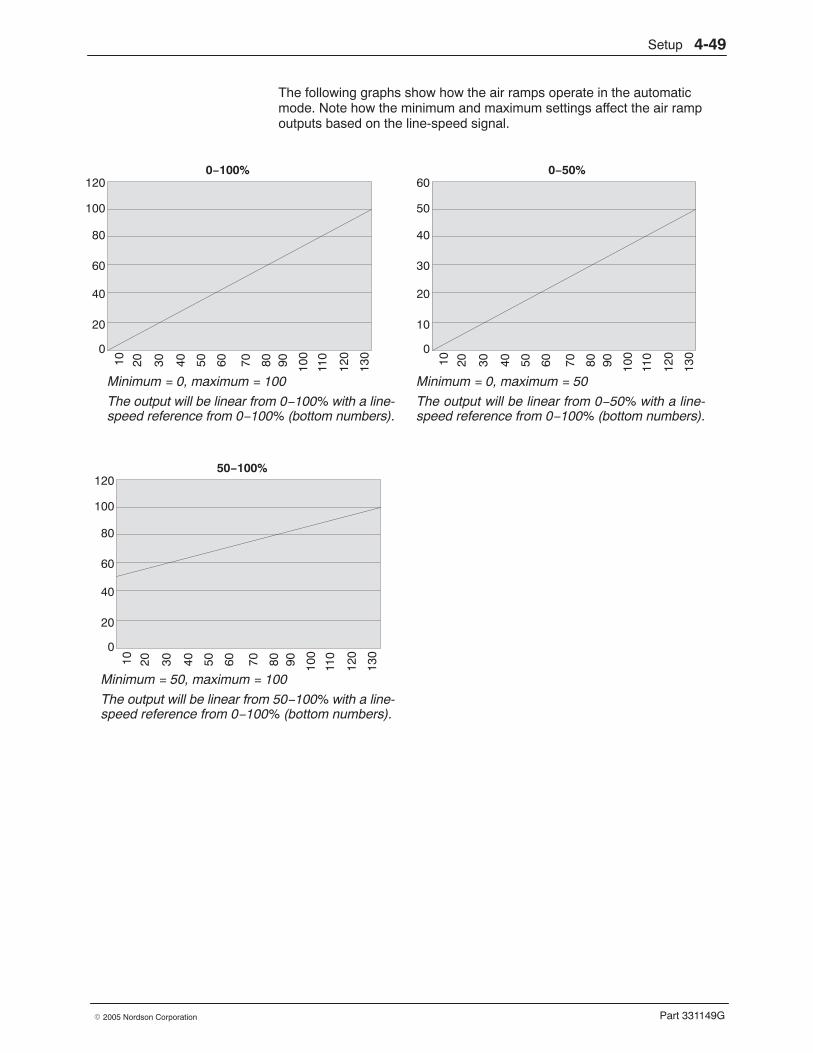
Setup 4-49
Part 331149G� 2005 Nordson Corporation
The following graphs show how the air ramps operate in the automaticmode. Note how the minimum and maximum settings affect the air rampoutputs based on the line-speed signal.
120
100
80
60
40
20
0
60
50
40
30
20
10
0
120
100
80
60
40
20
0
Minimum = 0, maximum = 100
The output will be linear from 0−100% with a line-speed reference from 0−100% (bottom numbers).
0−100% 0−50%
Minimum = 0, maximum = 50
The output will be linear from 0−50% with a line-speed reference from 0−100% (bottom numbers).
Minimum = 50, maximum = 100
The output will be linear from 50−100% with a line-speed reference from 0−100% (bottom numbers).
50−100%
10 20 30 40 50 60 70 80 90 100
110
120
130 10 20 30 40 50 60 70 80 90 100
110
120
130
10 20 30 40 50 60 70 80 90 100
110
120
130
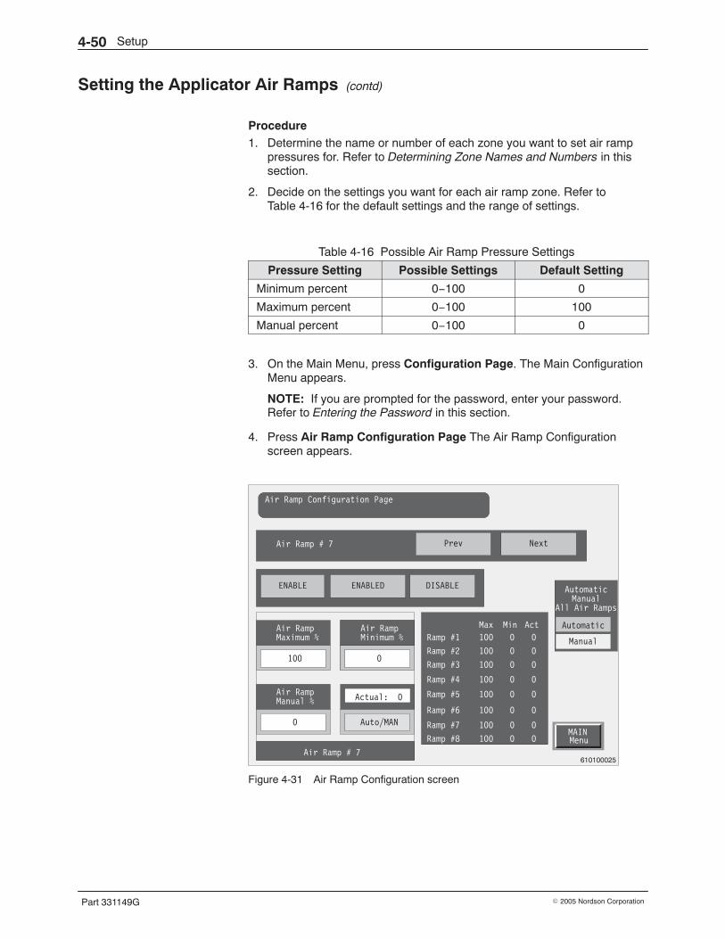
Setup4-50
Part 331149G � 2005 Nordson Corporation
Setting the Applicator Air Ramps (contd)
Procedure 1. Determine the name or number of each zone you want to set air ramp
pressures for. Refer to Determining Zone Names and Numbers in thissection.
2. Decide on the settings you want for each air ramp zone. Refer toTable 4-16 for the default settings and the range of settings.
Table 4-16 Possible Air Ramp Pressure Settings
Pressure Setting Possible Settings Default Setting
Minimum percent 0−100 0
Maximum percent 0−100 100
Manual percent 0−100 0
3. On the Main Menu, press Configuration Page. The Main ConfigurationMenu appears.
NOTE: If you are prompted for the password, enter your password.Refer to Entering the Password in this section.
4. Press Air Ramp Configuration Page The Air Ramp Configurationscreen appears.
MAINMenu
Air Ramp Configuration Page
610100025
Air Ramp # 7 Prev Next
ENABLE ENABLED DISABLE
Air RampMaximum %
100
Air RampMinimum %
100
Auto/MAN
Air RampMinimum %
0
Air RampManual %
0
Actual: 0
Air Ramp # 7
Ramp #1
Ramp #2
Ramp #3
Ramp #4
Ramp #5
Ramp #6
Ramp #7
Ramp #8
100
100
100
100
100
100
100
100
0
0
0
0
0
0
0
0
0
0
0
0
0
0
0
0
Max Min Act Automatic
Manual
AutomaticManual
All Air Ramps
Figure 4-31 Air Ramp Configuration screen
Setup 4-51
Part 331149G� 2005 Nordson Corporation
5. Press the Prev or Next buttons until the desired air ramp number isshown.
6. Press the Air Ramp Maximum %, Air Ramp Minimum %, and AirRamp Manual % buttons and enter the desired value for each. Thebutton displays update to show the new entries.
7. Press the Enable button to enable the air ramps.
8. Press the Automatic button to place the air ramp operation in theautomatic mode.
9. To exit the Air Ramp Configuration screen, press Main Menu.
10. Record your settings. The tables at the end of this section provide aplace to record all your settings.
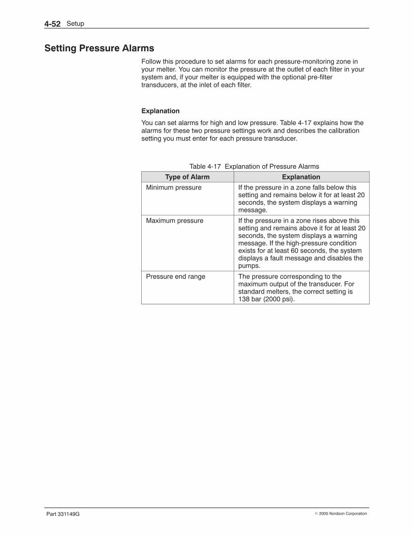
Setup4-52
Part 331149G � 2005 Nordson Corporation
Setting Pressure Alarms Follow this procedure to set alarms for each pressure-monitoring zone inyour melter. You can monitor the pressure at the outlet of each filter in yoursystem and, if your melter is equipped with the optional pre-filtertransducers, at the inlet of each filter.
Explanation
You can set alarms for high and low pressure. Table 4-17 explains how thealarms for these two pressure settings work and describes the calibrationsetting you must enter for each pressure transducer.
Table 4-17 Explanation of Pressure Alarms
Type of Alarm Explanation
Minimum pressure If the pressure in a zone falls below thissetting and remains below it for at least 20seconds, the system displays a warningmessage.
Maximum pressure If the pressure in a zone rises above thissetting and remains above it for at least 20seconds, the system displays a warningmessage. If the high-pressure conditionexists for at least 60 seconds, the systemdisplays a fault message and disables thepumps.
Pressure end range The pressure corresponding to themaximum output of the transducer. Forstandard melters, the correct setting is138 bar (2000 psi).
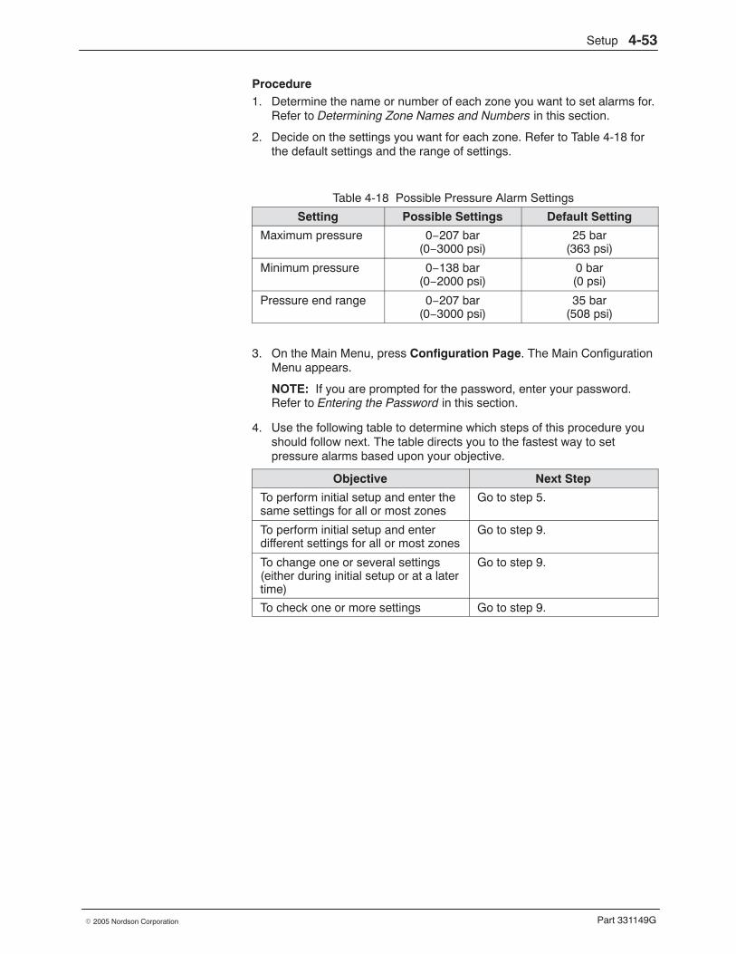
Setup 4-53
Part 331149G� 2005 Nordson Corporation
Procedure 1. Determine the name or number of each zone you want to set alarms for.
Refer to Determining Zone Names and Numbers in this section.
2. Decide on the settings you want for each zone. Refer to Table 4-18 forthe default settings and the range of settings.
Table 4-18 Possible Pressure Alarm Settings
Setting Possible Settings Default Setting
Maximum pressure 0−207 bar(0−3000 psi)
25 bar(363 psi)
Minimum pressure 0−138 bar(0−2000 psi)
0 bar(0 psi)
Pressure end range 0−207 bar(0−3000 psi)
35 bar(508 psi)
3. On the Main Menu, press Configuration Page. The Main ConfigurationMenu appears.
NOTE: If you are prompted for the password, enter your password.Refer to Entering the Password in this section.
4. Use the following table to determine which steps of this procedure youshould follow next. The table directs you to the fastest way to setpressure alarms based upon your objective.
Objective Next Step
To perform initial setup and enter thesame settings for all or most zones
Go to step 5.
To perform initial setup and enterdifferent settings for all or most zones
Go to step 9.
To change one or several settings(either during initial setup or at a latertime)
Go to step 9.
To check one or more settings Go to step 9.
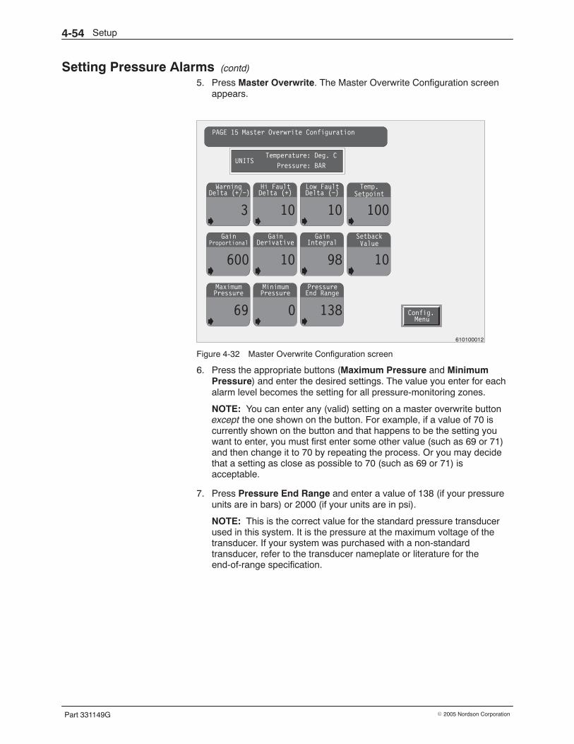
Setup4-54
Part 331149G � 2005 Nordson Corporation
Setting Pressure Alarms (contd)
5. Press Master Overwrite. The Master Overwrite Configuration screenappears.
Gain
600
ProportionalGain
10
DerivativeGain
98
IntegralSetback
10
Maximum
69
PressureMinimum
0
PressurePressure
138
End Range
Warning
3
Delta (+/−)Hi Fault
10
Delta (+)Low Fault
10
Delta (−)Temp.
100
Config.Menu
PAGE 15 Master Overwrite Configuration
UNITSTemperature: Deg. C
Pressure: BAR
Setpoint
Value
610100012
Figure 4-32 Master Overwrite Configuration screen
6. Press the appropriate buttons (Maximum Pressure and MinimumPressure) and enter the desired settings. The value you enter for eachalarm level becomes the setting for all pressure-monitoring zones.
NOTE: You can enter any (valid) setting on a master overwrite buttonexcept the one shown on the button. For example, if a value of 70 iscurrently shown on the button and that happens to be the setting youwant to enter, you must first enter some other value (such as 69 or 71)and then change it to 70 by repeating the process. Or you may decidethat a setting as close as possible to 70 (such as 69 or 71) isacceptable.
7. Press Pressure End Range and enter a value of 138 (if your pressureunits are in bars) or 2000 (if your units are in psi).
NOTE: This is the correct value for the standard pressure transducerused in this system. It is the pressure at the maximum voltage of thetransducer. If your system was purchased with a non-standardtransducer, refer to the transducer nameplate or literature for theend-of-range specification.
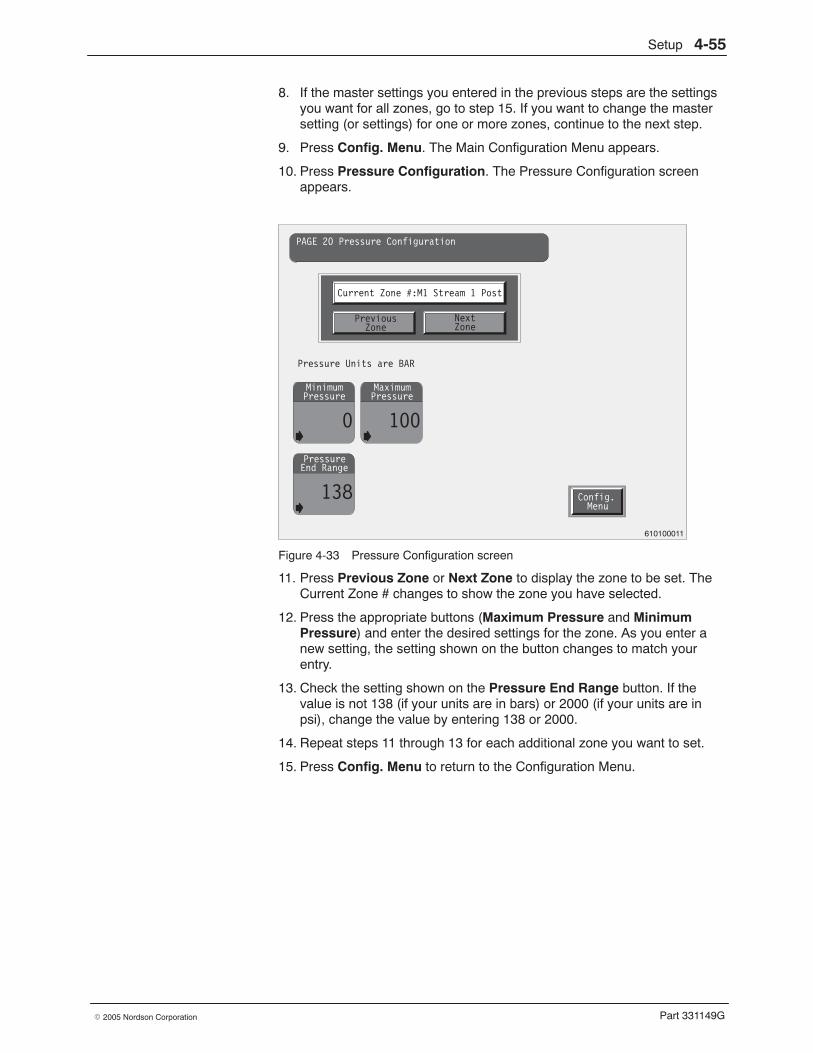
Setup 4-55
Part 331149G� 2005 Nordson Corporation
8. If the master settings you entered in the previous steps are the settingsyou want for all zones, go to step 15. If you want to change the mastersetting (or settings) for one or more zones, continue to the next step.
9. Press Config. Menu. The Main Configuration Menu appears.
10. Press Pressure Configuration. The Pressure Configuration screenappears.
Config.Menu
Minimum
0
PressureMaximum
100
Pressure
Pressure
138
End Range
PAGE 20 Pressure Configuration
Current Zone #:M1 Stream 1 Post
PreviousZone
NextZone
Pressure Units are BAR
610100011
Figure 4-33 Pressure Configuration screen
11. Press Previous Zone or Next Zone to display the zone to be set. TheCurrent Zone # changes to show the zone you have selected.
12. Press the appropriate buttons (Maximum Pressure and MinimumPressure) and enter the desired settings for the zone. As you enter anew setting, the setting shown on the button changes to match yourentry.
13. Check the setting shown on the Pressure End Range button. If thevalue is not 138 (if your units are in bars) or 2000 (if your units are inpsi), change the value by entering 138 or 2000.
14. Repeat steps 11 through 13 for each additional zone you want to set.
15. Press Config. Menu to return to the Configuration Menu.
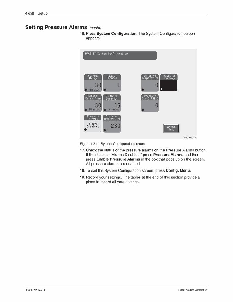
Setup4-56
Part 331149G � 2005 Nordson Corporation
Setting Pressure Alarms (contd)
16. Press System Configuration. The System Configuration screenappears.
Startup
30
Delay
AlarmsDisabled
PressureAlarms
Lead
1
Channel
Setback
30
Delay TimeSetback
45
Duration
Units of
0
Temperature
Pressure
0
Bar−0,PSI−1
Minutes
Shutdown
230
Temperature
AlarmsDisabled
Reset toFactory
Config.Menu
PAGE 17 System Configuration
Minutes Minutes
610100013
Figure 4-34 System Configuration screen
17. Check the status of the pressure alarms on the Pressure Alarms button.If the status is “Alarms Disabled,” press Pressure Alarms and thenpress Enable Pressure Alarms in the box that pops up on the screen.All pressure alarms are enabled.
18. To exit the System Configuration screen, press Config. Menu.
19. Record your settings. The tables at the end of this section provide aplace to record all your settings.

Setup 4-57
Part 331149G� 2005 Nordson Corporation
This page intentionally left blank.
Setup4-58
Part 331149G � 2005 Nordson Corporation
Saving Settings Follow this procedure to save your settings. For the procedure to load savedsettings, refer to Section 5, Operation.
Explanation
The saved settings feature allows you to save from two to five groups ofmelter settings (or recipes). You can then load any of these recipes at alater time when you want to run a different application. The number ofrecipes you can save depends on the type of PLC and the number oftemperature zones your melter has.
NOTE: This feature saves only process-related values: temperaturesetpoints, automatic pump ratios, and the line-speed reference setting. Thesaved information does not include settings such as alarms, temperatureoffsets, and sequential startup. These values remain the same when youchange settings groups unless you reset them individually.
Procedure 1. Follow the procedures described earlier in this section to enter
appropriate values for all the settings you want to save.
NOTE: If your current values have not been saved and you want tokeep them as a settings group or recipe, you must save them (using thisprocedure) before you start making changes. Then you can save therevised settings as another recipe (settings group).
2. On the Main Menu, press Saved Settings. The Saved Settings screenappears.
NOTE: If you are prompted for the password, enter your password.Refer to Entering the Password in this section.
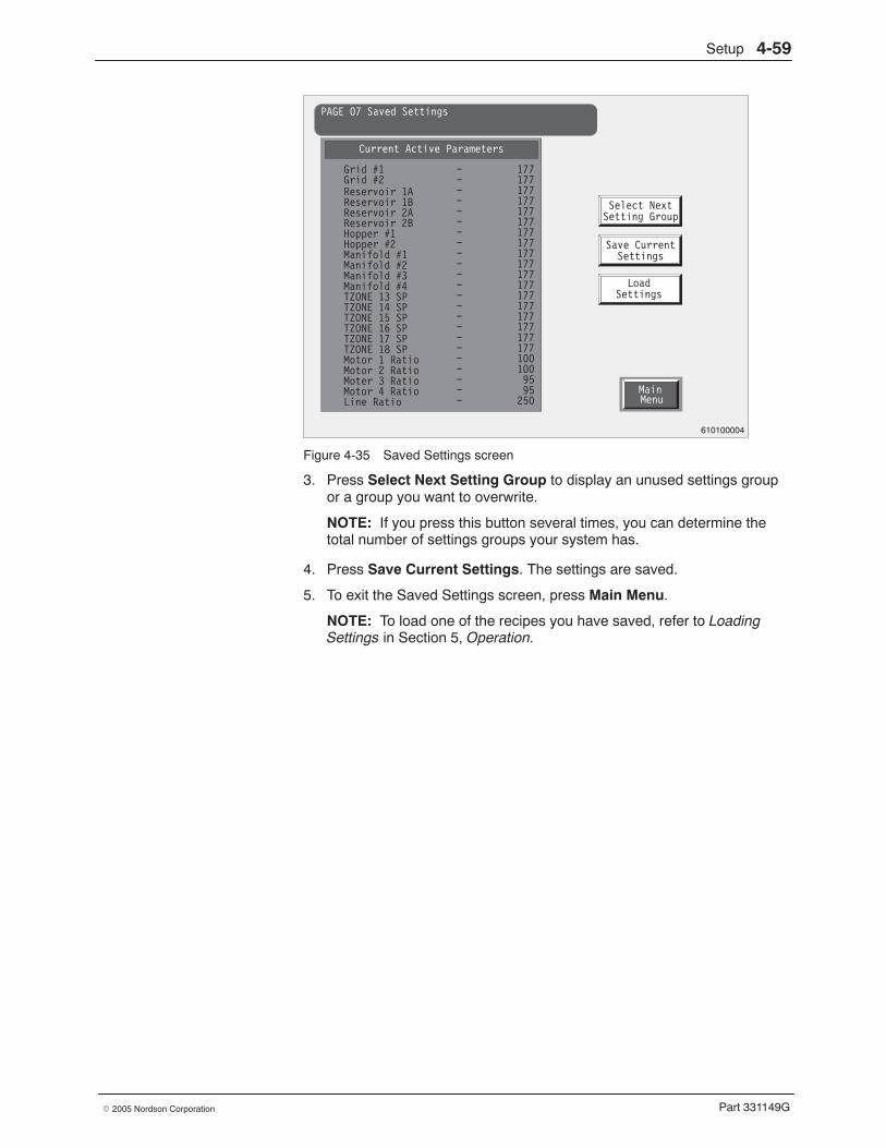
Setup 4-59
Part 331149G� 2005 Nordson Corporation
Save Current
Load
Settings
Settings
Select NextSetting Group
MainMenu
PAGE 07 Saved Settings
Current Active Parameters
Grid #1Grid #2Reservoir 1AReservoir 1BReservoir 2AReservoir 2BHopper #1Hopper #2Manifold #1Manifold #2Manifold #3Manifold #4TZONE 13 SPTZONE 14 SPTZONE 15 SPTZONE 16 SPTZONE 17 SPTZONE 18 SPMotor 1 RatioMotor 2 RatioMoter 3 RatioMotor 4 RatioLine Ratio
− 177−−−−−−−−−−−−−−−−−−−−−−
1771771771771771771771771771771771771771771771771771001009595
250
610100004
Figure 4-35 Saved Settings screen
3. Press Select Next Setting Group to display an unused settings groupor a group you want to overwrite.
NOTE: If you press this button several times, you can determine thetotal number of settings groups your system has.
4. Press Save Current Settings. The settings are saved.
5. To exit the Saved Settings screen, press Main Menu.
NOTE: To load one of the recipes you have saved, refer to LoadingSettings in Section 5, Operation.
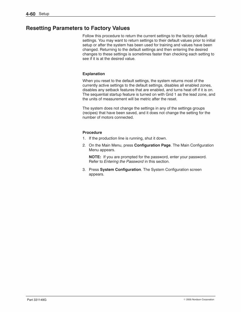
Setup4-60
Part 331149G � 2005 Nordson Corporation
Resetting Parameters to Factory Values Follow this procedure to return the current settings to the factory defaultsettings. You may want to return settings to their default values prior to initialsetup or after the system has been used for training and values have beenchanged. Returning to the default settings and then entering the desiredchanges to these settings is sometimes faster than checking each setting tosee if it is at the desired value.
Explanation
When you reset to the default settings, the system returns most of thecurrently active settings to the default settings, disables all enabled zones,disables any setback features that are enabled, and turns heat off if it is on.The sequential startup feature is turned on with Grid 1 as the lead zone, andthe units of measurement will be metric after the reset.
The system does not change the settings in any of the settings groups(recipes) that have been saved, and it does not change the setting for thenumber of motors connected.
Procedure 1. If the production line is running, shut it down.
2. On the Main Menu, press Configuration Page. The Main ConfigurationMenu appears.
NOTE: If you are prompted for the password, enter your password.Refer to Entering the Password in this section.
3. Press System Configuration. The System Configuration screenappears.
Setup 4-61
Part 331149G� 2005 Nordson Corporation
Startup
30
Delay
AlarmsDisabled
PressureAlarms
Lead
1
Channel
Setback
30
Delay TimeSetback
45
Duration
Units of
0
Temperature
Pressure
0
Bar−0,PSI−1
Minutes
Shutdown
230
Temperature
AlarmsDisabled
Reset toFactory
Config.Menu
PAGE 17 System Configuration
Minutes Minutes
610100013
Figure 4-36 System Configuration screen
4. Press Reset to Factory. The system resets values to the factorydefaults.
5. To exit the System Configuration screen, press Config. Menu.
Recording Your Settings Use the tables in the Records of Settings at the end of this section to recordyour settings and other key process information. If you have more than onegroup of settings (recipes) that you want to record, you can make copies ofthe tables.
Setup4-62
Part 331149G � 2005 Nordson Corporation
System Flushing The entire hot melt system should be flushed with adhesive before it isplaced into normal operation. Go to Flushing (Cleaning) the System inSection 6, Maintenance, to flush the system. Return here to continue.
Control Valve Adjustment The recirculation pressure of an adhesive stream is set by adjusting thecontrol valve for that stream. There are three types of control valve:pressure control valve (PCV), flow control valve (FCV), and air-operatedpressure control valve (AOPCV). Figure 4-37 shows the three types ofcontrol valve.
This part of Section 4 includes seven different procedures for adjusting therecirculation pressure in an adhesive stream: three for streams that supplypressure-fed applicators and four for steams that supply meteringapplicators. To select the correct procedure for any of the adhesive streamsyour melter produces, refer to Table 4-19 if the stream supplies apressure-fed applicator and to Table 4-20 if the stream supplies a meteringapplicator. A melter can produce from one to eight adhesive streams,depending upon the configuration of the melter.
Table 4-19 Recirculation Pressure Adjustment Procedures for Pressure-Fed Applicators
Type of ApplicatorType of Control Valve in
Melter Manifold(see Figure 4-37)
Procedure to Use
Pressure-fed Pressure control valve (PCV) Adjusting Recirculation Pressure: Pressure-FedApplicator/PCV
Pressure-fed Air-operated pressure controlvalve (AOPCV)
Adjusting Recirculation Pressure: Pressure-FedApplicator/AOPCV
Pressure-fed Flow control valve (FCV) Adjusting Recirculation Pressure: Pressure-FedApplicator/FCV
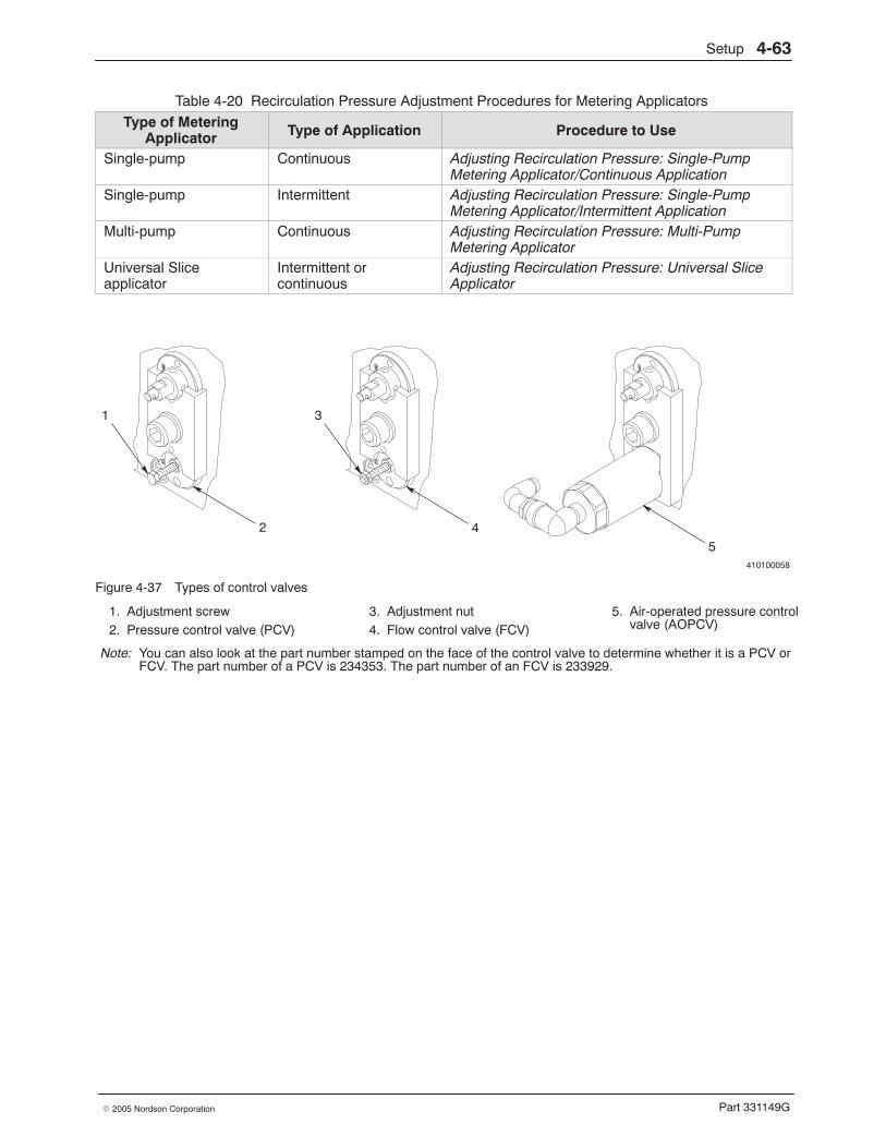
Setup 4-63
Part 331149G� 2005 Nordson Corporation
Table 4-20 Recirculation Pressure Adjustment Procedures for Metering Applicators
Type of MeteringApplicator Type of Application Procedure to Use
Single-pump Continuous Adjusting Recirculation Pressure: Single-PumpMetering Applicator/Continuous Application
Single-pump Intermittent Adjusting Recirculation Pressure: Single-PumpMetering Applicator/Intermittent Application
Multi-pump Continuous Adjusting Recirculation Pressure: Multi-PumpMetering Applicator
Universal Sliceapplicator
Intermittent orcontinuous
Adjusting Recirculation Pressure: Universal SliceApplicator
410100058
1 3
2 45
Figure 4-37 Types of control valves
1. Adjustment screw2. Pressure control valve (PCV)
3. Adjustment nut4. Flow control valve (FCV)
5. Air-operated pressure controlvalve (AOPCV)
Note: You can also look at the part number stamped on the face of the control valve to determine whether it is a PCV orFCV. The part number of a PCV is 234353. The part number of an FCV is 233929.
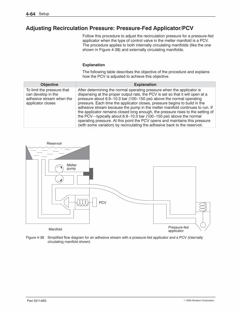
Setup4-64
Part 331149G � 2005 Nordson Corporation
Adjusting Recirculation Pressure: Pressure-Fed Applicator/PCV Follow this procedure to adjust the recirculation pressure for a pressure-fedapplicator when the type of control valve in the melter manifold is a PCV.The procedure applies to both internally circulating manifolds (like the oneshown in Figure 4-38) and externally circulating manifolds.
Explanation
The following table describes the objective of the procedure and explainshow the PCV is adjusted to achieve this objective.
Objective ExplanationTo limit the pressure thatcan develop in theadhesive stream when theapplicator closes
After determining the normal operating pressure when the applicator isdispensing at the proper output rate, the PCV is set so that it will open at apressure about 6.9−10.3 bar (100−150 psi) above the normal operatingpressure. Each time the applicator closes, pressure begins to build in theadhesive stream because the pump in the melter manifold continues to run. Ifthe applicator remains closed long enough, the pressure rises to the setting ofthe PCV—typically about 6.9−10.3 bar (100−150 psi) above the normaloperating pressure. At this point the PCV opens and maintains this pressure(with some variation) by recirculating the adhesive back to the reservoir.
Reservoir
Melterpump
PCV
Manifold Pressure-fedapplicator
Figure 4-38 Simplified flow diagram for an adhesive stream with a pressure-fed applicator and a PCV (internallycirculating manifold shown)
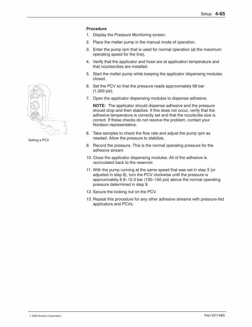
Setting a PCV
Setup 4-65
Part 331149G� 2005 Nordson Corporation
Procedure 1. Display the Pressure Monitoring screen.
2. Place the melter pump in the manual mode of operation.
3. Enter the pump rpm that is used for normal operation (at the maximumoperating speed for the line).
4. Verify that the applicator and hose are at application temperature andthat nozzles/dies are installed.
5. Start the melter pump while keeping the applicator dispensing modulesclosed.
6. Set the PCV so that the pressure reads approximately 69 bar(1,000 psi).
7. Open the applicator dispensing modules to dispense adhesive.
NOTE: The applicator should dispense adhesive and the pressureshould drop and then stabilize. If this does not occur, verify that theadhesive temperature is correctly set and that the nozzle/die size iscorrect. If these checks do not resolve the problem, contact yourNordson representative.
8. Take samples to check the flow rate and adjust the pump rpm asneeded. Allow the pressure to stabilize.
9. Record the pressure. This is the normal operating pressure for theadhesive stream.
10. Close the applicator dispensing modules. All of the adhesive isrecirculated back to the reservoir.
11. With the pump running at the same speed that was set in step 3 (oradjusted in step 8), turn the PCV clockwise until the pressure isapproximately 6.9−10.3 bar (100−150 psi) above the normal operatingpressure determined in step 9.
12. Secure the locking nut on the PCV.
13. Repeat this procedure for any other adhesive streams with pressure-fedapplicators and PCVs.
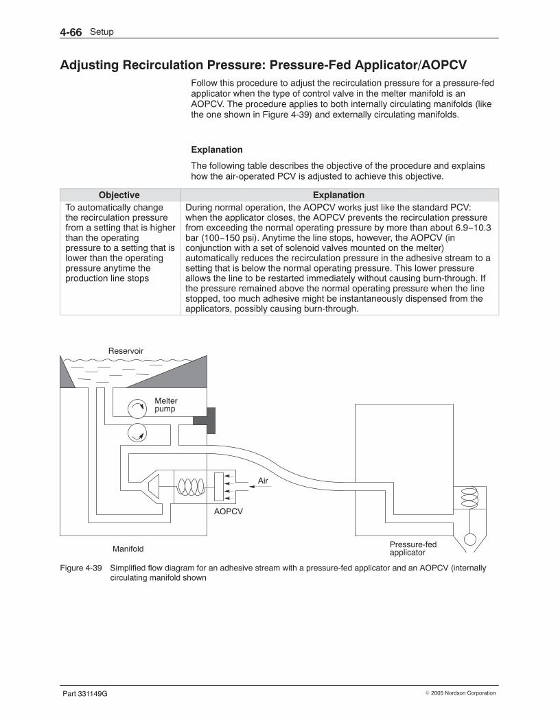
Setup4-66
Part 331149G � 2005 Nordson Corporation
Adjusting Recirculation Pressure: Pressure-Fed Applicator/AOPCV Follow this procedure to adjust the recirculation pressure for a pressure-fedapplicator when the type of control valve in the melter manifold is anAOPCV. The procedure applies to both internally circulating manifolds (likethe one shown in Figure 4-39) and externally circulating manifolds.
Explanation
The following table describes the objective of the procedure and explainshow the air-operated PCV is adjusted to achieve this objective.
Objective ExplanationTo automatically changethe recirculation pressurefrom a setting that is higherthan the operatingpressure to a setting that islower than the operatingpressure anytime theproduction line stops
During normal operation, the AOPCV works just like the standard PCV:when the applicator closes, the AOPCV prevents the recirculation pressurefrom exceeding the normal operating pressure by more than about 6.9−10.3bar (100−150 psi). Anytime the line stops, however, the AOPCV (inconjunction with a set of solenoid valves mounted on the melter)automatically reduces the recirculation pressure in the adhesive stream to asetting that is below the normal operating pressure. This lower pressureallows the line to be restarted immediately without causing burn-through. Ifthe pressure remained above the normal operating pressure when the linestopped, too much adhesive might be instantaneously dispensed from theapplicators, possibly causing burn-through.
Reservoir
Melterpump
AOPCV
Manifold Pressure-fedapplicator
Air
Figure 4-39 Simplified flow diagram for an adhesive stream with a pressure-fed applicator and an AOPCV (internallycirculating manifold shown
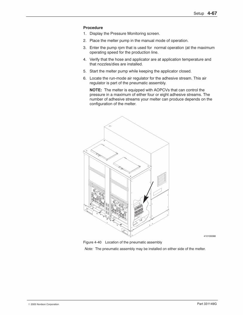
Setup 4-67
Part 331149G� 2005 Nordson Corporation
Procedure 1. Display the Pressure Monitoring screen.
2. Place the melter pump in the manual mode of operation.
3. Enter the pump rpm that is used for normal operation (at the maximumoperating speed for the production line.
4. Verify that the hose and applicator are at application temperature andthat nozzles/dies are installed.
5. Start the melter pump while keeping the applicator closed.
6. Locate the run-mode air regulator for the adhesive stream. This airregulator is part of the pneumatic assembly.
NOTE: The melter is equipped with AOPCVs that can control thepressure in a maximum of either four or eight adhesive streams. Thenumber of adhesive streams your melter can produce depends on theconfiguration of the melter.
410100068
Figure 4-40 Location of the pneumatic assembly
Note: The pneumatic assembly may be installed on either side of the melter.
Setup4-68
Part 331149G � 2005 Nordson Corporation
Procedure (contd)
7. Energize the AOPCV solenoid valve that corresponds to the adhesivestream being measured. This action activates the run-mode pressuresetting of the AOPCV.
8. Adjust the pressure at the run-mode air regulator so that the adhesivepressure reads approximately 69 bar (1,000 psi).
9. Open the applicator dispensing modules.
NOTE: The applicator should dispense adhesive and the pressureshould drop and then stabilize. If this does not occur, verify that theadhesive temperature is correctly set and that the nozzle/die size iscorrect. If these checks do not resolve the problem, contact yourNordson representative.
10. Record the adhesive pressure. This is the normal operating pressure forthe adhesive stream.
11. Close the applicator dispensing modules. All of the adhesive isrecirculated back to the reservoir.
12. With the pump running at the same speed that was set in step 3,increase the setting at the run-mode air regulator until the adhesivepressure reads approximately 6.9−10.3 bar (100−150 psi) higher thanthe pressure you recorded in step 6. This is the maximum pressure inthe stream when the applicator closes and all of the adhesive isrecirculated back to the reservoir.
13. De-energize the AOPCV solenoid. This action activates the stop-modepressure setting of the AOPCV.
14. Locate the stop-mode air regulator of the AOPCV. This regulator is atthe left end of the pneumatic assembly.
15. Adjust the air regulator until the adhesive pressure is the desiredminimum pressure for the stream (and all other streams) when theproduction line is stopped. This adhesive pressure will drop to thispressure anytime the line stops.
16. Repeat this procedure (except for steps 13−15) for any other adhesivestreams with pressure-fed applicators and AOPCVs.
Setup 4-69
Part 331149G� 2005 Nordson Corporation
Adjusting Recirculation Pressure: Pressure-Fed Applicator/FCV Follow this procedure to adjust the recirculation pressure for a pressure-fedapplicator when the type of control valve in the melter manifold is an FCV.
Explanation
The following table describes the objective of the procedure and explainshow the FCV is adjusted to achieve this objective.
Objective ExplanationTo set the recirculationpressure (the pressurewhen the applicator isclosed) to the samepressure that exists whenthe applicator is open
After determining the normal operating pressure when the applicator isdispensing, the applicator is closed so that all of the adhesive is recirculated.The FCV is adjusted so that the recirculation pressure is the same as theoperating pressure. This setup prevents the pressure buildup that occurswhen the applicator closes in a system with a PCV, especially when there isa long interval before the applicator reopens. The result is more consistentpatterns, with even adhesive distribution from beginning to end.
Reservoir
Melterpump
FCV
ManifoldPressure-fed
Returnvalve
applicator
Figure 4-41 Simplified flow diagram for an adhesive stream with a pressure-fed applicator and an FCV
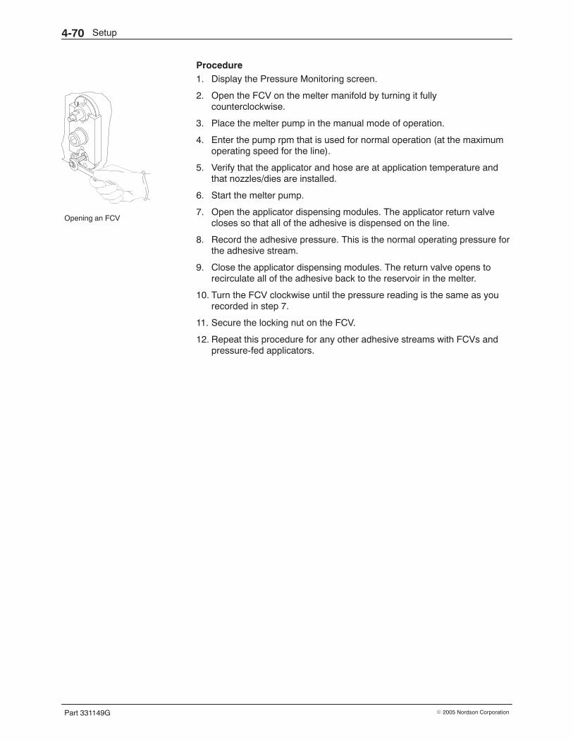
Opening an FCV
Setup4-70
Part 331149G � 2005 Nordson Corporation
Procedure 1. Display the Pressure Monitoring screen.
2. Open the FCV on the melter manifold by turning it fullycounterclockwise.
3. Place the melter pump in the manual mode of operation.
4. Enter the pump rpm that is used for normal operation (at the maximumoperating speed for the line).
5. Verify that the applicator and hose are at application temperature andthat nozzles/dies are installed.
6. Start the melter pump.
7. Open the applicator dispensing modules. The applicator return valvecloses so that all of the adhesive is dispensed on the line.
8. Record the adhesive pressure. This is the normal operating pressure forthe adhesive stream.
9. Close the applicator dispensing modules. The return valve opens torecirculate all of the adhesive back to the reservoir in the melter.
10. Turn the FCV clockwise until the pressure reading is the same as yourecorded in step 7.
11. Secure the locking nut on the FCV.
12. Repeat this procedure for any other adhesive streams with FCVs andpressure-fed applicators.
Setup 4-71
Part 331149G� 2005 Nordson Corporation
Adjusting Recirculation Pressure: Single-Pump Metering Applicator in aContinuous Application
Follow this procedure to adjust the recirculation pressure for a single-pumpmetering applicator in a continuous application.
NOTE: This procedure is written for adhesive streams that supply a singlemetering applicator. If the adhesive stream supplies more than one meteringapplicator, use this same procedure with the necessary modifications insome of the steps.
Explanation
The following table describes the objective of the procedure and explainshow the PCV is adjusted to achieve this objective.
Objective ExplanationTo ensure that a sufficientfeed pressure exists in thesupply to the applicatormetering pump
To ensure a sufficient supply of adhesive, the melter pump is set to provideabout 25% more adhesive than the applicator pump dispenses on theproduction line. While the applicator pump is off and all of the adhesive isrecirculating, the PCV is set to 13.8 bar (200 psi). Then the applicator isstarted. If the pressure drops, the PCV is adjusted to maintain a minimumfeed pressure of at least 13.8 bar (200 psi). Maintaining a sufficient feedpressure prevents cavitation of the applicator pump.
Reservoir
Melterpump
PCV
ManifoldMetering applicator
Applicatorpump
Returnvalve
PCV
PressuregaugeP
Figure 4-42 Simplified flow diagram for an adhesive stream that supplies a single-pump metering applicator in acontinuous application
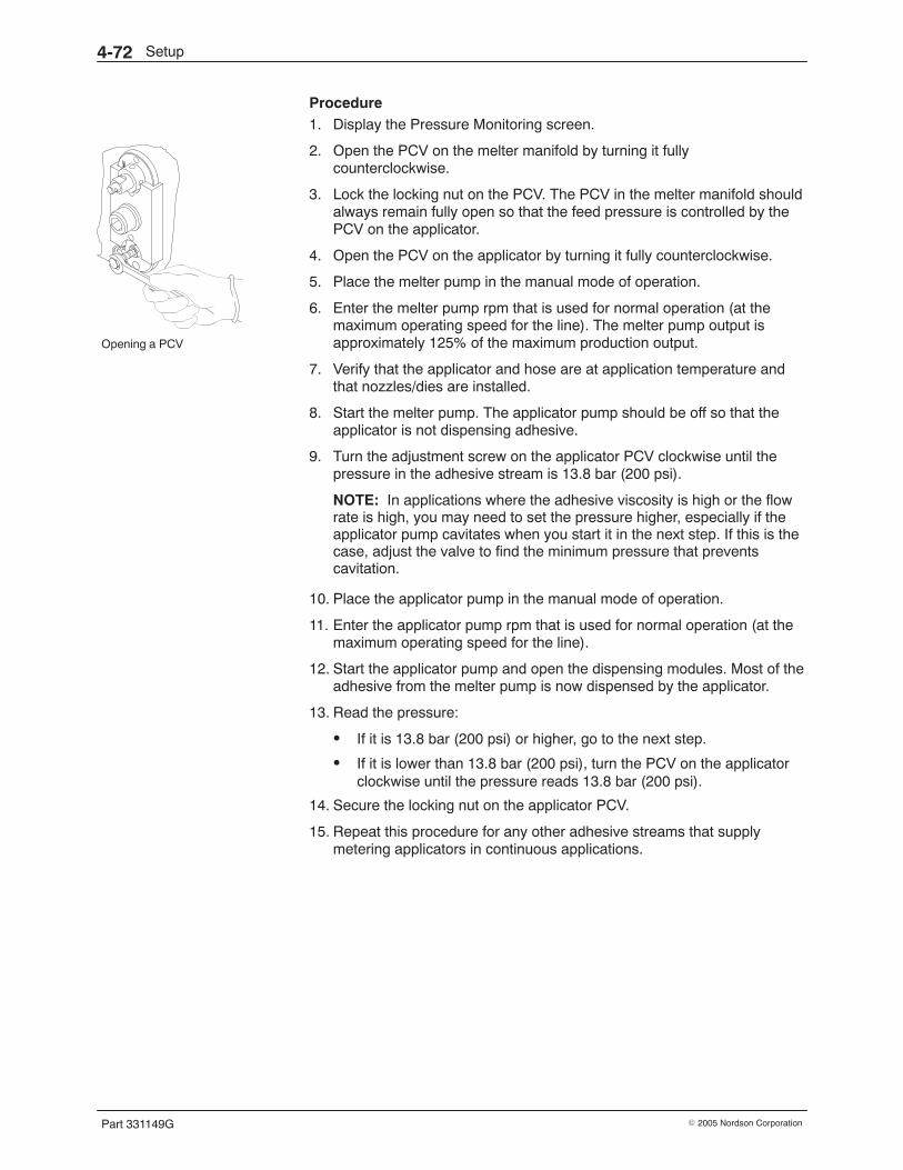
Opening a PCV
Setup4-72
Part 331149G � 2005 Nordson Corporation
Procedure 1. Display the Pressure Monitoring screen.
2. Open the PCV on the melter manifold by turning it fullycounterclockwise.
3. Lock the locking nut on the PCV. The PCV in the melter manifold shouldalways remain fully open so that the feed pressure is controlled by thePCV on the applicator.
4. Open the PCV on the applicator by turning it fully counterclockwise.
5. Place the melter pump in the manual mode of operation.
6. Enter the melter pump rpm that is used for normal operation (at themaximum operating speed for the line). The melter pump output isapproximately 125% of the maximum production output.
7. Verify that the applicator and hose are at application temperature andthat nozzles/dies are installed.
8. Start the melter pump. The applicator pump should be off so that theapplicator is not dispensing adhesive.
9. Turn the adjustment screw on the applicator PCV clockwise until thepressure in the adhesive stream is 13.8 bar (200 psi).
NOTE: In applications where the adhesive viscosity is high or the flowrate is high, you may need to set the pressure higher, especially if theapplicator pump cavitates when you start it in the next step. If this is thecase, adjust the valve to find the minimum pressure that preventscavitation.
10. Place the applicator pump in the manual mode of operation.
11. Enter the applicator pump rpm that is used for normal operation (at themaximum operating speed for the line).
12. Start the applicator pump and open the dispensing modules. Most of theadhesive from the melter pump is now dispensed by the applicator.
13. Read the pressure:
� If it is 13.8 bar (200 psi) or higher, go to the next step.
� If it is lower than 13.8 bar (200 psi), turn the PCV on the applicatorclockwise until the pressure reads 13.8 bar (200 psi).
14. Secure the locking nut on the applicator PCV.
15. Repeat this procedure for any other adhesive streams that supplymetering applicators in continuous applications.
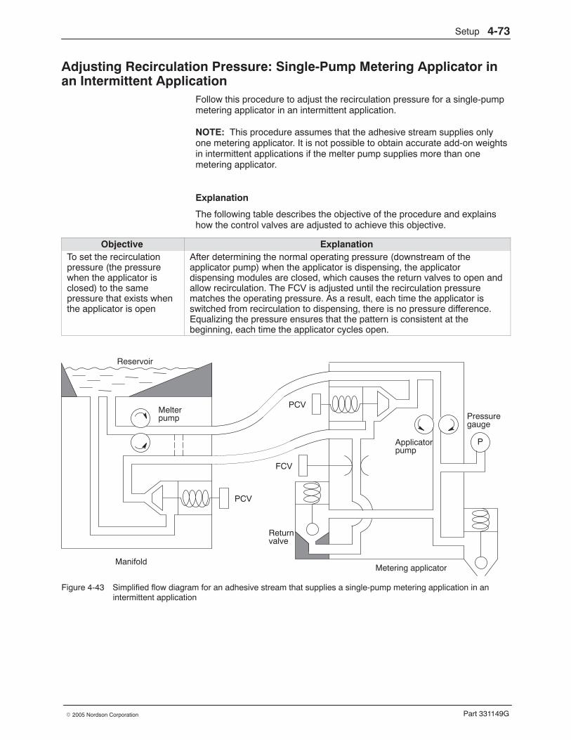
Setup 4-73
Part 331149G� 2005 Nordson Corporation
Adjusting Recirculation Pressure: Single-Pump Metering Applicator inan Intermittent Application
Follow this procedure to adjust the recirculation pressure for a single-pumpmetering applicator in an intermittent application.
NOTE: This procedure assumes that the adhesive stream supplies onlyone metering applicator. It is not possible to obtain accurate add-on weightsin intermittent applications if the melter pump supplies more than onemetering applicator.
Explanation
The following table describes the objective of the procedure and explainshow the control valves are adjusted to achieve this objective.
Objective ExplanationTo set the recirculationpressure (the pressurewhen the applicator isclosed) to the samepressure that exists whenthe applicator is open
After determining the normal operating pressure (downstream of theapplicator pump) when the applicator is dispensing, the applicatordispensing modules are closed, which causes the return valves to open andallow recirculation. The FCV is adjusted until the recirculation pressurematches the operating pressure. As a result, each time the applicator isswitched from recirculation to dispensing, there is no pressure difference.Equalizing the pressure ensures that the pattern is consistent at thebeginning, each time the applicator cycles open.
Reservoir
Melterpump
PCV
ManifoldMetering applicator
Applicatorpump
Returnvalve
PCV
FCV
Pressuregauge
P
Figure 4-43 Simplified flow diagram for an adhesive stream that supplies a single-pump metering application in anintermittent application
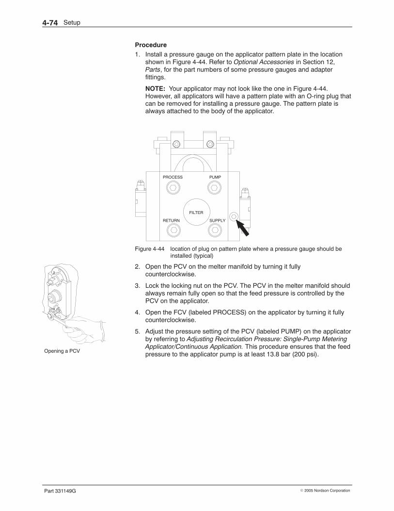
Opening a PCV
Setup4-74
Part 331149G � 2005 Nordson Corporation
Procedure 1. Install a pressure gauge on the applicator pattern plate in the location
shown in Figure 4-44. Refer to Optional Accessories in Section 12,Parts, for the part numbers of some pressure gauges and adapterfittings.
NOTE: Your applicator may not look like the one in Figure 4-44.However, all applicators will have a pattern plate with an O-ring plug thatcan be removed for installing a pressure gauge. The pattern plate isalways attached to the body of the applicator.
Figure 4-44 location of plug on pattern plate where a pressure gauge should beinstalled (typical)
2. Open the PCV on the melter manifold by turning it fullycounterclockwise.
3. Lock the locking nut on the PCV. The PCV in the melter manifold shouldalways remain fully open so that the feed pressure is controlled by thePCV on the applicator.
4. Open the FCV (labeled PROCESS) on the applicator by turning it fullycounterclockwise.
5. Adjust the pressure setting of the PCV (labeled PUMP) on the applicatorby referring to Adjusting Recirculation Pressure: Single-Pump MeteringApplicator/Continuous Application. This procedure ensures that the feedpressure to the applicator pump is at least 13.8 bar (200 psi).
Setup 4-75
Part 331149G� 2005 Nordson Corporation
6. Verify that the applicator and hose are at application temperature andthat nozzles/dies are installed.
7. With the applicator open and the applicator pump running at its normaloperating speed, record the pressure shown on the applicator pressuregauge.
8. Close the applicator dispensing modules. The return valves on theapplicator open and recirculate all of the adhesive back to the reservoir.
9. Turn the FCV on the applicator clockwise until the pressure reading onthe applicator pressure gauge is the same as you recorded in step 6.
10. Secure the locking nut on the FCV.
11. Repeat this procedure for any other adhesive streams that supplymetering applicators in intermittent applications.
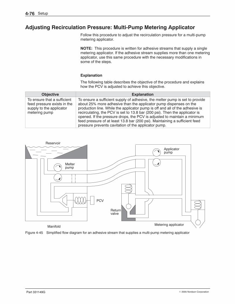
Setup4-76
Part 331149G � 2005 Nordson Corporation
Adjusting Recirculation Pressure: Multi-Pump Metering Applicator Follow this procedure to adjust the recirculation pressure for a multi-pumpmetering applicator.
NOTE: This procedure is written for adhesive streams that supply a singlemetering applicator. If the adhesive stream supplies more than one meteringapplicator, use this same procedure with the necessary modifications insome of the steps.
Explanation
The following table describes the objective of the procedure and explainshow the PCV is adjusted to achieve this objective.
Objective ExplanationTo ensure that a sufficientfeed pressure exists in thesupply to the applicatormetering pump
To ensure a sufficient supply of adhesive, the melter pump is set to provideabout 25% more adhesive than the applicator pump dispenses on theproduction line. While the applicator pump is off and all of the adhesive isrecirculating, the PCV is set to 13.8 bar (200 psi). Then the applicator isopened. If the pressure drops, the PCV is adjusted to maintain a minimumfeed pressure of at least 13.8 bar (200 psi). Maintaining a sufficient feedpressure prevents cavitation of the applicator pump.
Reservoir
Melterpump
PCV
Manifold Metering applicator
Applicatorpump
Returnvalve
Figure 4-45 Simplified flow diagram for an adhesive stream that supplies a multi-pump metering applicator
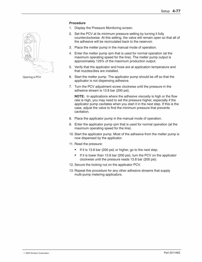
Opening a PCV
Setup 4-77
Part 331149G� 2005 Nordson Corporation
Procedure 1. Display the Pressure Monitoring screen.
2. Set the PCV at its minimum pressure setting by turning it fullycounterclockwise. At this setting, the valve will remain open so that all ofthe adhesive will be recirculated back to the reservoir.
3. Place the melter pump in the manual mode of operation.
4. Enter the melter pump rpm that is used for normal operation (at themaximum operating speed for the line). The melter pump output isapproximately 125% of the maximum production output.
5. Verify that the applicator and hose are at application temperature andthat nozzles/dies are installed.
6. Start the melter pump. The applicator pump should be off so that theapplicator is not dispensing adhesive.
7. Turn the PCV adjustment screw clockwise until the pressure in theadhesive stream is 13.8 bar (200 psi).
NOTE: In applications where the adhesive viscosity is high or the flowrate is high, you may need to set the pressure higher, especially if theapplicator pump cavitates when you start it in the next step. If this is thecase, adjust the valve to find the minimum pressure that preventscavitation.
8. Place the applicator pump in the manual mode of operation.
9. Enter the applicator pump rpm that is used for normal operation (at themaximum operating speed for the line).
10. Start the applicator pump. Most of the adhesive from the melter pump isnow dispensed by the applicator.
11. Read the pressure:
� If it is 13.8 bar (200 psi) or higher, go to the next step.
� If it is lower than 13.8 bar (200 psi), turn the PCV on the applicatorclockwise until the pressure reads 13.8 bar (200 psi).
12. Secure the locking nut on the applicator PCV.
13. Repeat this procedure for any other adhesive streams that supplymulti-pump metering applicators.
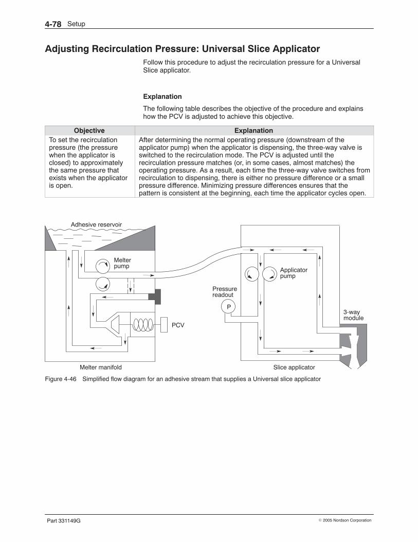
Setup4-78
Part 331149G � 2005 Nordson Corporation
Adjusting Recirculation Pressure: Universal Slice Applicator Follow this procedure to adjust the recirculation pressure for a UniversalSlice applicator.
Explanation
The following table describes the objective of the procedure and explainshow the PCV is adjusted to achieve this objective.
Objective ExplanationTo set the recirculationpressure (the pressurewhen the applicator isclosed) to approximatelythe same pressure thatexists when the applicatoris open.
After determining the normal operating pressure (downstream of theapplicator pump) when the applicator is dispensing, the three-way valve isswitched to the recirculation mode. The PCV is adjusted until therecirculation pressure matches (or, in some cases, almost matches) theoperating pressure. As a result, each time the three-way valve switches fromrecirculation to dispensing, there is either no pressure difference or a smallpressure difference. Minimizing pressure differences ensures that thepattern is consistent at the beginning, each time the applicator cycles open.
Adhesive reservoir
Melterpump
PCV
Melter manifold Slice applicator
Applicatorpump
Pressurereadout
3-waymodule
P
Figure 4-46 Simplified flow diagram for an adhesive stream that supplies a Universal slice applicator
Setup 4-79
Part 331149G� 2005 Nordson Corporation
Procedure 1. Adjust the pressure setting of the PCV in the melter manifold by
referring to Adjusting Recirculation Pressure: Multi-Pump MeteringApplicator. This procedure ensures that the applicator pump has asufficient feed pressure.
2. Verify that the applicator pump is set to the manual mode of operation.Also verify that the applicator pump rpm is set to the speed used fornormal operation (at the maximum operating speed for the line).
3. Display the pressure readout for the Slice applicator.
NOTE: To perform step 3, the Slice applicator must be equipped withthe optional pressure transducer.
4. Verify that the applicator and hose are at application temperature andthat nozzles/dies are installed.
5. Start the applicator pump and actuate the three-way valve to dispenseadhesive.
6. Record the pressure at the applicator. This is the dispensing pressure.
7. De-energize the three-way valve so that all of the adhesive isrecirculated.
8. Adjust the PCV in the melter manifold as follows:
� If the pressure recorded in step 5 was above 6.9 bar (100 psi),adjust the PCV until the pressure at the applicator reads the sameas in step 5.
� If the pressure recorded in step 5 was 6.9 bar (100 psi) or below,adjust the PCV until the pressure at the applicator is 6.9 bar(100 psi).
NOTE: If you have difficulty obtaining accurate add-on weights, contactyour Nordson representative.
9. Tighten the locking nut on the PCV.
10. Repeat this procedure for any other adhesive streams that supplyUniversal Slice applicators.
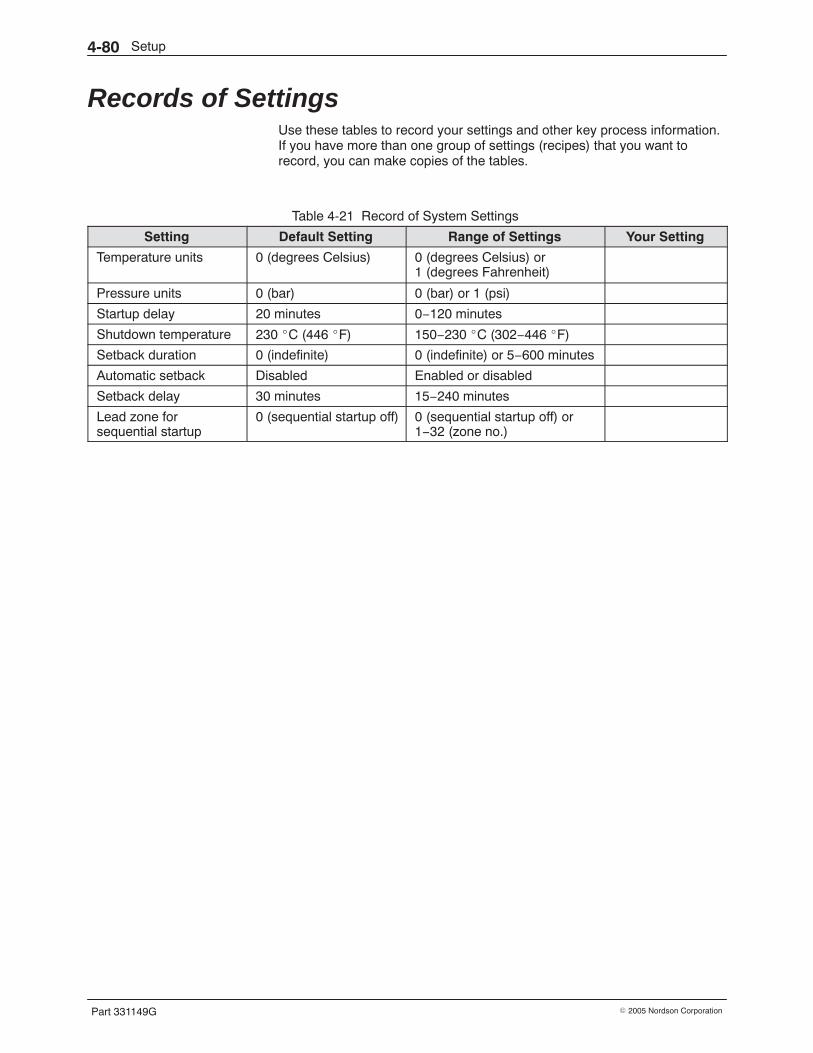
Setup4-80
Part 331149G � 2005 Nordson Corporation
Records of Settings Use these tables to record your settings and other key process information.If you have more than one group of settings (recipes) that you want torecord, you can make copies of the tables.
Table 4-21 Record of System Settings
Setting Default Setting Range of Settings Your Setting
Temperature units 0 (degrees Celsius) 0 (degrees Celsius) or1 (degrees Fahrenheit)
Pressure units 0 (bar) 0 (bar) or 1 (psi)
Startup delay 20 minutes 0−120 minutes
Shutdown temperature 230 �C (446 �F) 150−230 �C (302−446 �F)
Setback duration 0 (indefinite) 0 (indefinite) or 5−600 minutes
Automatic setback Disabled Enabled or disabled
Setback delay 30 minutes 15−240 minutes
Lead zone forsequential startup
0 (sequential startup off) 0 (sequential startup off) or1−32 (zone no.)
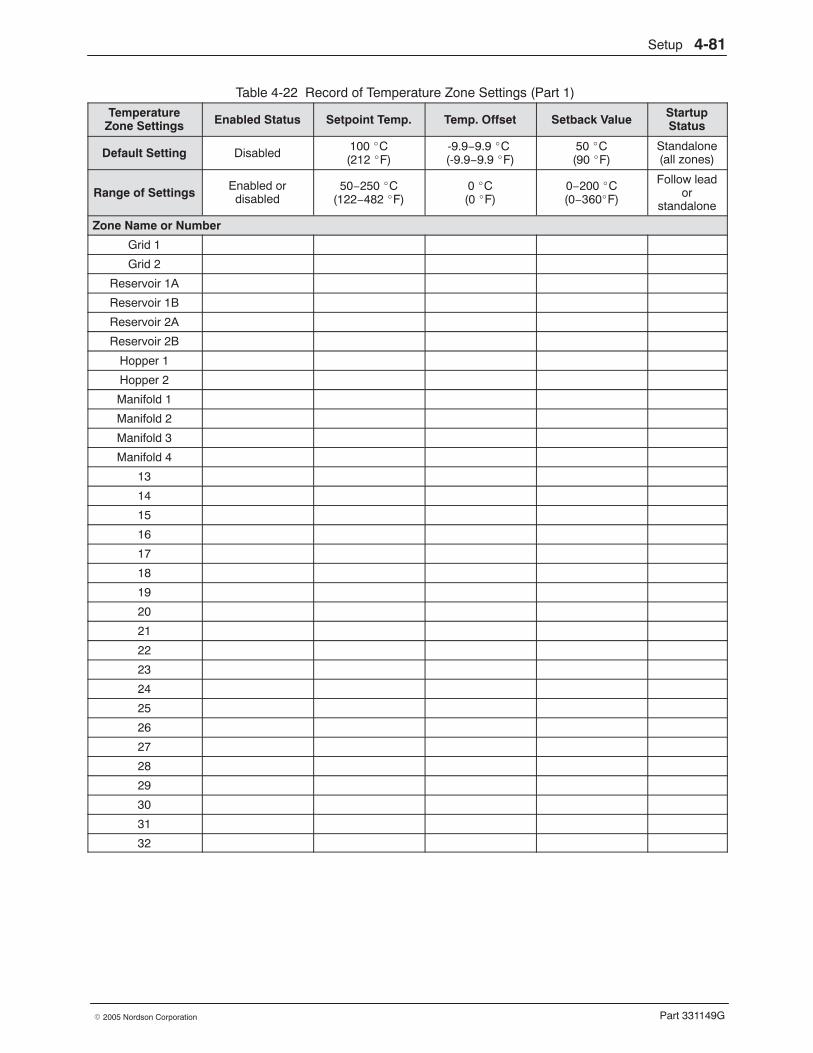
Setup 4-81
Part 331149G� 2005 Nordson Corporation
Table 4-22 Record of Temperature Zone Settings (Part 1)
TemperatureZone Settings Enabled Status Setpoint Temp. Temp. Offset Setback Value Startup
Status
Default Setting Disabled 100 �C(212 �F)
-9.9−9.9 �C (-9.9−9.9 �F)
50 �C(90 �F)
Standalone(all zones)
Range of Settings Enabled ordisabled
50−250 �C(122−482 �F)
0 �C(0 �F)
0−200 �C(0−360�F)
Follow leador
standalone
Zone Name or Number
Grid 1
Grid 2
Reservoir 1A
Reservoir 1B
Reservoir 2A
Reservoir 2B
Hopper 1
Hopper 2
Manifold 1
Manifold 2
Manifold 3
Manifold 4
13
14
15
16
17
18
19
20
21
22
23
24
25
26
27
28
29
30
31
32
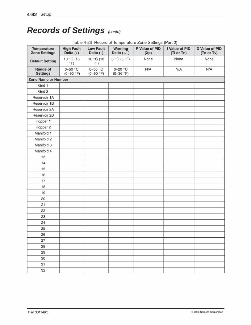
Setup4-82
Part 331149G � 2005 Nordson Corporation
Records of Settings (contd)
Table 4-23 Record of Temperature Zone Settings (Part 2)
TemperatureZone Settings
High FaultDelta (+)
Low FaultDelta (−)
WarningDelta (+/−)
P Value of PID(Xp)
I Value of PID(Ti or Tn)
D Value of PID(Td or Tv)
Default Setting 10 �C (18�F)
10 �C (18�F)
3 �C (5 �F) None None None
Range ofSettings
0−50 �C (0−90 �F)
0−50 �C(0−90 �F)
0−20 �C(0−36 �F)
N/A N/A N/A
Zone Name or Number
Grid 1
Grid 2
Reservoir 1A
Reservoir 1B
Reservoir 2A
Reservoir 2B
Hopper 1
Hopper 2
Manifold 1
Manifold 2
Manifold 3
Manifold 4
13
14
15
16
17
18
19
20
21
22
23
24
25
26
27
28
29
30
31
32
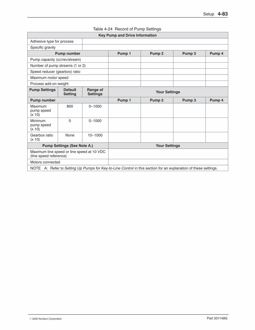
Setup 4-83
Part 331149G� 2005 Nordson Corporation
Table 4-24 Record of Pump Settings
Key Pump and Drive Information
Adhesive type for process
Specific gravity
Pump number Pump 1 Pump 2 Pump 3 Pump 4
Pump capacity (cc/rev/stream)
Number of pump streams (1 or 2)
Speed reducer (gearbox) ratio
Maximum motor speed
Process add-on weight
Pump Settings DefaultSetting
Range ofSettings Your Settings
Pump number Pump 1 Pump 2 Pump 3 Pump 4
Maximumpump speed(x 10)
800 0−1000
Minimumpump speed(x 10)
0 0−1000
Gearbox ratio(x 10)
None 10−1000
Pump Settings (See Note A.) Your Settings
Maximum line speed or line speed at 10 VDC(line speed reference)
Motors connected
NOTE A: Refer to Setting Up Pumps for Key-to-Line Control in this section for an explanation of these settings.
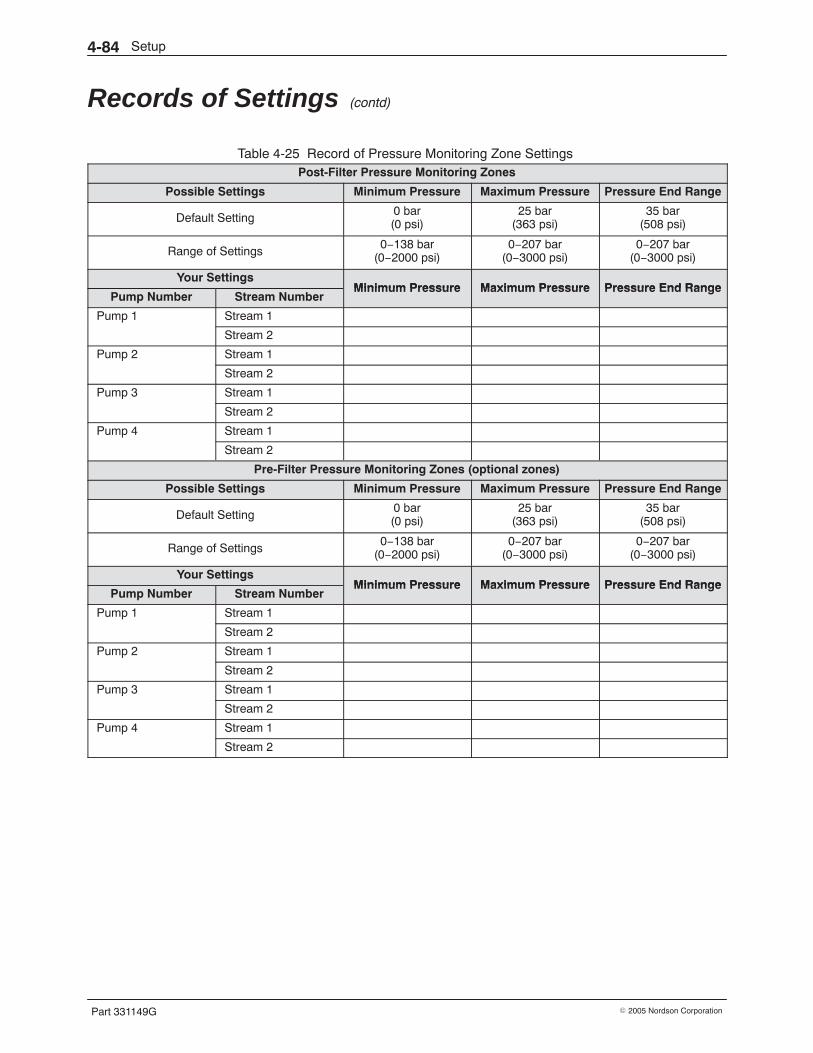
Setup4-84
Part 331149G � 2005 Nordson Corporation
Records of Settings (contd)
Table 4-25 Record of Pressure Monitoring Zone Settings Post-Filter Pressure Monitoring Zones
Possible Settings Minimum Pressure Maximum Pressure Pressure End Range
Default Setting0 bar(0 psi)
25 bar(363 psi)
35 bar(508 psi)
Range of Settings0−138 bar
(0−2000 psi)0−207 bar
(0−3000 psi)0−207 bar
(0−3000 psi)
Your SettingsMinimum Pressure Maximum Pressure Pressure End Range
Pump Number Stream NumberMinimum Pressure Maximum Pressure Pressure End Range
Pump 1 Stream 1p
Stream 2
Pump 2 Stream 1p
Stream 2
Pump 3 Stream 1p
Stream 2
Pump 4 Stream 1p
Stream 2
Pre-Filter Pressure Monitoring Zones (optional zones)
Possible Settings Minimum Pressure Maximum Pressure Pressure End Range
Default Setting0 bar(0 psi)
25 bar(363 psi)
35 bar(508 psi)
Range of Settings0−138 bar
(0−2000 psi)0−207 bar
(0−3000 psi)0−207 bar
(0−3000 psi)
Your SettingsMinimum Pressure Maximum Pressure Pressure End Range
Pump Number Stream NumberMinimum Pressure Maximum Pressure Pressure End Range
Pump 1 Stream 1p
Stream 2
Pump 2 Stream 1p
Stream 2
Pump 3 Stream 1p
Stream 2
Pump 4 Stream 1p
Stream 2
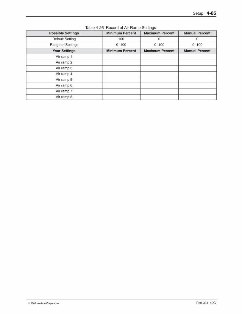
Setup 4-85
Part 331149G� 2005 Nordson Corporation
Table 4-26 Record of Air Ramp Settings Possible Settings Minimum Percent Maximum Percent Manual Percent
Default Setting 100 0 0
Range of Settings 0−100 0−100 0−100
Your Settings Minimum Percent Maximum Percent Manual PercentYour Settings Minimum Percent Maximum Percent Manual Percent
Air ramp 1
Air ramp 2
Air ramp 3
Air ramp 4
Air ramp 5
Air ramp 6
Air ramp 7
Air ramp 8

Setup4-86
Part 331149G � 2005 Nordson Corporation
Operation 5-1
Part 331149G� 2005 Nordson Corporation
Section 5Operation
WARNING: Allow only personnel with appropriate training and experienceto operate or service the equipment. The use of untrained or inexperiencedpersonnel to operate or service the equipment can result in injury, includingdeath, to themselves and others, and damage to the equipment.
Introduction This section provides procedures for operating a melter that uses either aPanelMate or PanelView operator interface. Before operating the melter forthe first time, make sure you have
� completed the mechanical and electrical installation procedures inSection 3, Installation
� set up the control system for your operation using Section 4, Setup
� flushed the system and adjusted the control valves as described inSection 4, Setup
For basic information about using the operator interface, such as how todetermine zone numbers or enter values, refer to System Navigation andInterface in Section 4, Setup.
NOTE: Nordson gives you the option of two different operator interfaces:PanelMate or PanelView. Sample screens from a system with thePanelMate interface are used to illustrate the procedures in this manual, butthe PanelView screens are similar in appearance and function. If yourmelter has an operator interface other than PanelMate or PanelView,contact your Nordson representative as needed for assistance in operatingthe system.
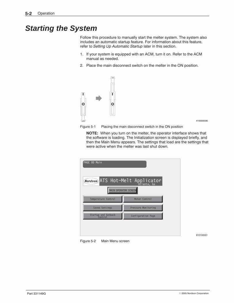
Operation5-2
Part 331149G � 2005 Nordson Corporation
Starting the System Follow this procedure to manually start the melter system. The system alsoincludes an automatic startup feature. For information about this feature,refer to Setting Up Automatic Startup later in this section.
1. If your system is equipped with an ACM, turn it on. Refer to the ACMmanual as needed.
2. Place the main disconnect switch on the melter in the ON position.
410000006OFF
ON
Figure 5-1 Placing the main disconnect switch in the ON position
NOTE: When you turn on the melter, the operator interface shows thatthe software is loading. The Initialization screen is displayed briefly, andthen the Main Menu appears. The settings that load are the settings thatwere active when the melter was last shut down.
PAGE 00 Main
ATS Hot−Melt ApplicatorAtlanta, Ga
MAIN OPERATOR SCREEN
Temperature Control Motor Control
Saved Settings Pressure Monitoring
Startup and Setback Configuration PageControl
610100001
Figure 5-2 Main Menu screen
Operation 5-3
Part 331149G� 2005 Nordson Corporation
3. If the melter motor disconnect switch is OFF, turn it to the ON position.
410000005
OFF
ON
Figure 5-3 Placing the motor disconnect switch in the ON position
4. On the Main Menu, press Temperature Control. The TemperatureControl screen appears.
NOTE: If you are prompted for the password, enter your password. Forinformation on how to do this, refer to Entering the Password inSection 4, Setup.
Heat Status
Zone:
Status:
AllEnabled
Zone 13
Enabled
Temperature Zone Control
MasterEnable
MotorControl
MainMenu
Zone Action
Enable
Disable
Next
Previous
Zone Select
Next
23170
Temperature Page #1
Off
Temperatures in Deg. C
Heat isOn
HeatControlHeat isOff
HeatControl
Grid #1 Grid #2
24170
Manifold
23170
# 1Hopper 2
24170
Hopper 1
25170
Reservoir
23170
# 1BReservoir
23170
# 2AReservoir
23170
# 2B
Reservoir
23170
# 1A
Master
175
Setpoint
Zone Action
Enable
Disable
Previous
610100044
Figure 5-4 Temperature Control screen
5. Press Next (or Previous) to verify that the status of each temperaturezone is correct: either “Zone Enabled” or “Zone Disabled.” To changethe status of a zone, press Enable or Disable.
6. If your system does not have level control, check the level of adhesive inthe hopper. If the hopper is less than 50% full, add adhesive to bring thelevel to within 25 mm (1 in.) of the top of the hopper.
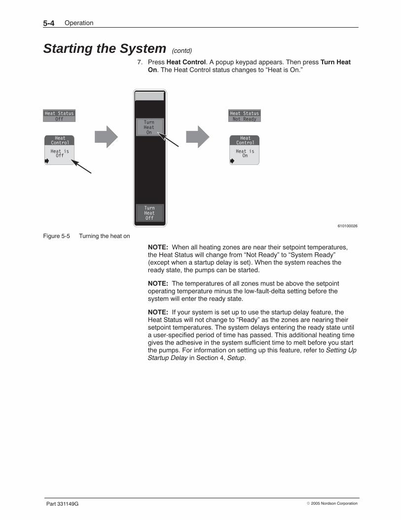
Operation5-4
Part 331149G � 2005 Nordson Corporation
Starting the System (contd)
7. Press Heat Control. A popup keypad appears. Then press Turn HeatOn. The Heat Control status changes to “Heat is On.”
610100026
Heat isOff
HeatControl
Heat StatusOff
Heat isOn
HeatControl
Heat StatusNot Ready
TurnHeatOn
TurnHeatOff
Figure 5-5 Turning the heat on
NOTE: When all heating zones are near their setpoint temperatures,the Heat Status will change from “Not Ready” to “System Ready”(except when a startup delay is set). When the system reaches theready state, the pumps can be started.
NOTE: The temperatures of all zones must be above the setpointoperating temperature minus the low-fault-delta setting before thesystem will enter the ready state.
NOTE: If your system is set up to use the startup delay feature, theHeat Status will not change to “Ready” as the zones are nearing theirsetpoint temperatures. The system delays entering the ready state untila user-specified period of time has passed. This additional heating timegives the adhesive in the system sufficient time to melt before you startthe pumps. For information on setting up this feature, refer to Setting UpStartup Delay in Section 4, Setup.
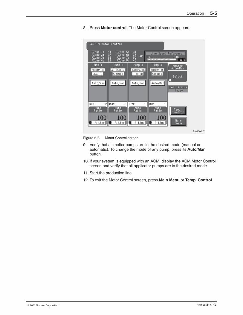
Operation 5-5
Part 331149G� 2005 Nordson Corporation
8. Press Motor control. The Motor Control screen appears.
Auto
100% Line
RatioAuto
100% Line
Ratio Temp.Control
MainMenu
PAGE 09 Motor Control
Auto
100% Line
Ratio
RPM: 52 RPM: 51 RPM: 70
Auto/Man Auto/Man Auto/Man
PZone 1:PZone 2:PZone 3:PZone 4:
41375229
PZone 5:PZone 6:PZone 7:PZone 8:
31335046
BAR
Pump 1 Pump 2 Pump 3
Line Speed Reference0% 100%
Pump 4
Heat StatusReady
MasterAuto/Man
Select
AUTOMATIC
STARTED
AUTOMATIC
STARTED
AUTOMATIC
STARTED
80%
AUTOMATIC
Auto
100% Line
Ratio
RPM: 61
Auto/Man
Pump 4
STARTED
610100047
Figure 5-6 Motor Control screen
9. Verify that all melter pumps are in the desired mode (manual orautomatic). To change the mode of any pump, press its Auto/Manbutton.
10. If your system is equipped with an ACM, display the ACM Motor Controlscreen and verify that all applicator pumps are in the desired mode.
11. Start the production line.
12. To exit the Motor Control screen, press Main Menu or Temp. Control.
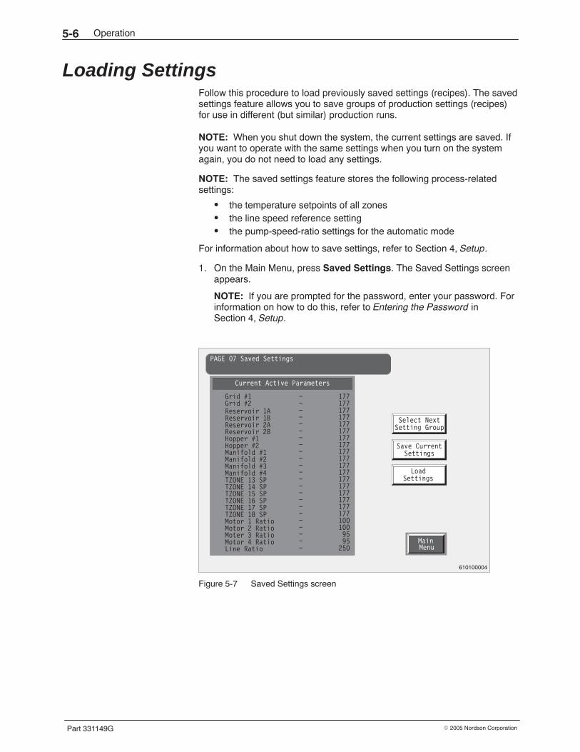
Operation5-6
Part 331149G � 2005 Nordson Corporation
Loading Settings Follow this procedure to load previously saved settings (recipes). The savedsettings feature allows you to save groups of production settings (recipes)for use in different (but similar) production runs.
NOTE: When you shut down the system, the current settings are saved. Ifyou want to operate with the same settings when you turn on the systemagain, you do not need to load any settings.
NOTE: The saved settings feature stores the following process-relatedsettings:
� the temperature setpoints of all zones� the line speed reference setting� the pump-speed-ratio settings for the automatic mode
For information about how to save settings, refer to Section 4, Setup.
1. On the Main Menu, press Saved Settings. The Saved Settings screenappears.
NOTE: If you are prompted for the password, enter your password. Forinformation on how to do this, refer to Entering the Password inSection 4, Setup.
Save Current
Load
Settings
Settings
Select NextSetting Group
MainMenu
PAGE 07 Saved Settings
Current Active Parameters
Grid #1Grid #2Reservoir 1AReservoir 1BReservoir 2AReservoir 2BHopper #1Hopper #2Manifold #1Manifold #2Manifold #3Manifold #4TZONE 13 SPTZONE 14 SPTZONE 15 SPTZONE 16 SPTZONE 17 SPTZONE 18 SPMotor 1 RatioMotor 2 RatioMoter 3 RatioMotor 4 RatioLine Ratio
− 177−−−−−−−−−−−−−−−−−−−−−−
1771771771771771771771771771771771771771771771771771001009595
250
610100004
Figure 5-7 Saved Settings screen
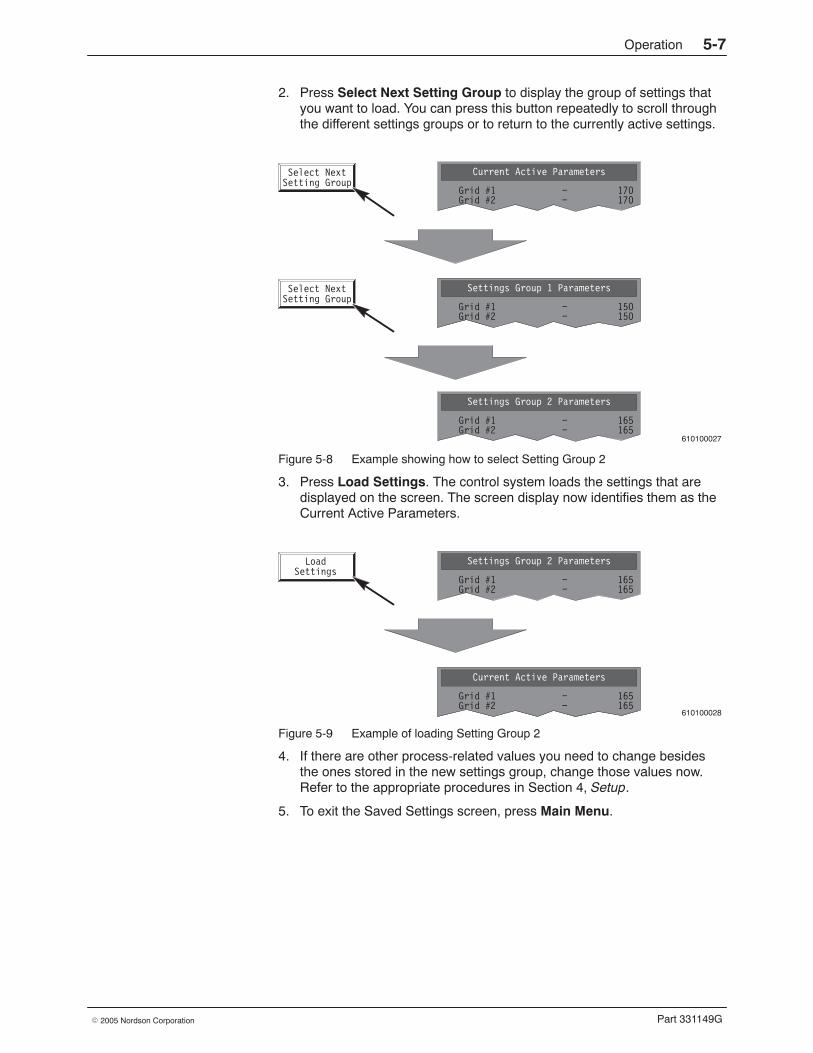
Operation 5-7
Part 331149G� 2005 Nordson Corporation
2. Press Select Next Setting Group to display the group of settings thatyou want to load. You can press this button repeatedly to scroll throughthe different settings groups or to return to the currently active settings.
610100027
Select NextSetting Group
Current Active Parameters
Grid #1Grid #2
− 170− 170
Select NextSetting Group
Current Active Parameters
Grid #1Grid #2
− 170− 170
Settings Group 1 Parameters
Grid #1Grid #2
− 150− 150
Settings Group 2 Parameters
Grid #1Grid #2
− 165− 165
Figure 5-8 Example showing how to select Setting Group 2
3. Press Load Settings. The control system loads the settings that aredisplayed on the screen. The screen display now identifies them as theCurrent Active Parameters.
610100028
LoadSettings
Settings Group 2 Parameters
Grid #1Grid #2
− 165− 165
Current Active Parameters
Grid #1Grid #2
− 170− 170
Current Active Parameters
Grid #1Grid #2
− 165− 165
Figure 5-9 Example of loading Setting Group 2
4. If there are other process-related values you need to change besidesthe ones stored in the new settings group, change those values now.Refer to the appropriate procedures in Section 4, Setup.
5. To exit the Saved Settings screen, press Main Menu.
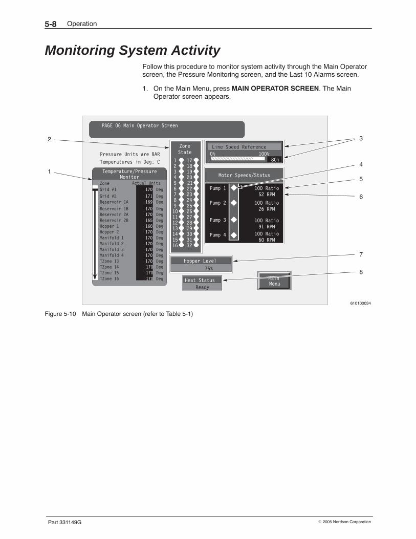
Operation5-8
Part 331149G � 2005 Nordson Corporation
Monitoring System Activity Follow this procedure to monitor system activity through the Main Operatorscreen, the Pressure Monitoring screen, and the Last 10 Alarms screen.
1. On the Main Menu, press MAIN OPERATOR SCREEN. The MainOperator screen appears.
610100034
MainMenu
PAGE 06 Main Operator Screen
Heat Status
Ready
ZoneState
12345678910111213141516
17181920212223242526272829303132
Pump 1
Pump 2
Pump 3
Pump 4
100 Ratio52 RPM
100 Ratio26 RPM
100 Ratio91 RPM
100 Ratio60 RPM
Motor Speeds/Status
Hopper Level
75%
Temperatures in Deg. C
Pressure Units are BAR
Temperature/PressureMonitor
Zone Actual Units
170 DegGrid #1
Grid #2Reservoir 1A
Reservoir 1BReservoir 2AReservoir 2BHopper 1Hopper 2Manifold 1Manifold 2Manifold 3Manifold 4TZone 13TZone 14TZone 15TZone 16
171169
170170165168170170170170170170170170170
DegDeg
DegDegDegDegDegDegDegDegDegDegDegDegDeg
Line Speed Reference
0% 100%80%
2
15
4
6
7
8
3
Figure 5-10 Main Operator screen (refer to Table 5-1)
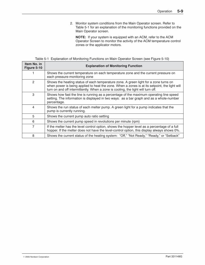
Operation 5-9
Part 331149G� 2005 Nordson Corporation
2. Monitor system conditions from the Main Operator screen. Refer toTable 5-1 for an explanation of the monitoring functions provided on theMain Operator screen.
NOTE: If your system is equipped with an ACM, refer to the ACMOperator Screen to monitor the activity of the ACM temperature controlzones or the applicator motors.
Table 5-1 Explanation of Monitoring Functions on Main Operator Screen (see Figure 5-10)
Item No. inFigure 5-10 Explanation of Monitoring Function
1 Shows the current temperature on each temperature zone and the current pressure oneach pressure-monitoring zone
2 Shows the heating status of each temperature zone. A green light for a zone turns onwhen power is being applied to heat the zone. When a zones is at its setpoint, the light willturn on and off intermittently. When a zone is cooling, the light will turn off.
3 Shows how fast the line is running as a percentage of the maximum operating line speedsetting. The information is displayed in two ways: as a bar graph and as a whole-numberpercentage.
4 Shows the run status of each melter pump. A green light for a pump indicates that thepump is currently running.
5 Shows the current pump auto ratio setting
6 Shows the current pump speed in revolutions per minute (rpm)
7 If the melter has the level control option, shows the hopper level as a percentage of a fullhopper. If the melter does not have the level-control option, this display always shows 0%.
8 Shows the current status of the heating system: “Off,” “Not Ready,” “Ready,” or “Setback”
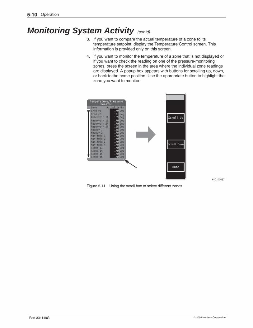
Operation5-10
Part 331149G � 2005 Nordson Corporation
Monitoring System Activity (contd)
3. If you want to compare the actual temperature of a zone to itstemperature setpoint, display the Temperature Control screen. Thisinformation is provided only on this screen.
4. If you want to monitor the temperature of a zone that is not displayed orif you want to check the reading on one of the pressure-monitoringzones, press the screen in the area where the individual zone readingsare displayed. A popup box appears with buttons for scrolling up, down,or back to the home position. Use the appropriate button to highlight thezone you want to monitor.
610100037
Temperature/PressureMonitor
Zone Actual Units170 DegGrid #1
Grid #2Reservoir 1AReservoir 1BReservoir 2AReservoir 2BHopper 1Hopper 2Manifold 1Manifold 2Manifold 3Manifold 4TZone 13TZone 14TZone 15TZone 16
171169170170165168170170170170170170170170170
DegDegDegDegDegDegDegDegDegDegDegDegDegDegDeg
Scroll Down
Scroll Up
Home
Figure 5-11 Using the scroll box to select different zones
Operation 5-11
Part 331149G� 2005 Nordson Corporation
5. If you want to see only the pressure-monitoring zones, press MainMenu to exit the screen and then, from the Main Menu, press PressureMonitoring. The Pressure Monitoring screen appears. You can read thepressure on any of the zones that your system is equipped to monitor.
NOTE: Some of the pressure-monitoring zones shown on the screenmay not be active. Only manifolds that contain dual-stream pumps areequipped to monitor pressure on stream 2. And only systems that areequipped with optional pre-filter pressure transducers can display thepre-filter system pressure.
Stream #2Pre Post
Stream #1Pre Post
Stream #2Pre Post
Stream #1Pre Post
Stream #2Pre PostPump #4
Stream #1Pre Post
Stream #2Pre Post
PAGE 10 Pressure Monitoring
MainMenu
Pump #1Stream #1
Pre Post
Pump #2
Pump #3
Pressure Units are BAR
75 70 72 68
82 77 80 75
60 51 55 50
90 80 85 80
610100007
Figure 5-12 Pressure Monitoring screen
Operation5-12
Part 331149G � 2005 Nordson Corporation
Monitoring System Activity (contd)
6. To see the last ten alarms that have occurred, press Main Menu toreturn to the Main Menu. Then press Configuration Page on the MainMenu and View Last Ten Alarms on the Main Configuration Menu. TheLast 10 Alarms screen appears, displaying the most recent alarm at thetop of the list.
7. To exit the screen, press Main Menu.
Config.Menu
PAGE 19 Last 10 Alarms
Alarm description Date TimeMotor #4 Frequency Inverter Fault1.
2.
3.
4.
5.
6.
7.
8.
9.
10.
Data Valve Out of Range − 457
TZONE1 High Temperature Fault
TZONE2 High Temperature Fault
WARNING: Motor #1 Running and Bypass is Op
No Alarm Recorded for this Memory Location
No Alarm Recorded for this Memory Location
No Alarm Recorded for this Memory Location
9/14 15:28
9/14 15:33
9/14 15:43
9/14 15:47
9/14 15:49
9/14 15:54
6/22 12:38
TZONE1 High Temperature Fault
WARNING: Motor #1 Running and Bypass is Op
610100014
Figure 5-13 Last 10 Alarms screen
Operation 5-13
Part 331149G� 2005 Nordson Corporation
Operating a Pump in the Manual Mode Follow this procedure to manually control the output of a pump. The pumpswork differently in the manual and automatic modes:
� In the manual mode, you can control pump output by setting a pumpspeed in revolutions per minute (rpm), and you can start or stop apump.
� In the automatic mode, you can control pump output by changing theratio of pump speed to line speed, but you cannot start or stop apump from the operator interface. In an emergency, you can stop thepumps by placing the motor disconnect switch on the melter in theOFF position, or, if the melter is equipped with the XL3 input/outputoption, you can stop or start each pump remotely.
NOTE: When a pump is placed in the manual mode of operation, it runs atthe speed you set and is not affected by line speed if the line is running. Forinformation about how to set up the pumps for the automatic mode ofoperation, refer to Setting Up Pumps for Key-to-Line Control in Section 4,Setup. For information about how to adjust pump output in the automaticmode, refer to the next procedure, Adjusting Pump Output in the AutomaticMode.
1. See Figure 5-14. Determine the number for the pump (or pumps) youwant to operate.
Figure 5-14 Location of pump numbers
Operation5-14
Part 331149G � 2005 Nordson Corporation
Operating a Pump in the Manual Mode (contd)
2. On the Main Menu, press Motor Control. The Motor Control screenappears.
NOTE: If you are prompted for the password, enter your password. Forinformation on how to do this, refer to Entering the Password inSection 4, Setup.
NOTE: If your system is equipped with an ACM, display the ACM MotorControl Screen to operate the applicator pumps.
Manual
15RPM
Pump SpeedManual
53RPM
Pump Speed Temp.Control
MainMenu
PAGE 09 Motor Control
Manual
80RPM
Pump Speed
START
STOP
RPM: 0 RPM: 0 RPM: 0
Auto/Man
START
STOP
Auto/Man
START
STOP
Auto/Man
PZone 1:PZone 2:PZone 3:PZone 4:
0040
PZone 5:PZone 6:PZone 7:PZone 8:
0000
BAR
Pump 1 Pump 2 Pump 3
Line Speed Reference0% 100%
Pump 4
Heat StatusReady
MasterAuto/Man
Select
MANUAL
STOPPED
MANUAL
STOPPED
MANUAL
STOPPED
80%
AUTOMATIC
Auto
95% Line
Ratio
RPM: 0
Auto/Man
Pump 4
STOPPED
610100046
Figure 5-15 Motor Control screen
Operation 5-15
Part 331149G� 2005 Nordson Corporation
3. Determine from the screen whether the pump you want to operate is inthe manual mode or automatic mode (see Figure 5-15). If the pump is inthe automatic mode, press Auto/Man (automatic/manual) to place thepump in the manual mode. The pump display changes to show thepump in the manual mode.
NOTE: You can change the status of all pumps from automatic tomanual by pressing Master Auto/Man and then pressing Manual in thebox that pops up on the screen.
610100051
AUTOMATIC
Auto
100% Line
Ratio
RPM: 0
Auto/Man
Pump 1
STOPPED
Manual
10RPM
Pump Speed
START
STOP
RPM: 0
Auto/Man
Pump 1
MANUAL
STOPPED
Figure 5-16 Changing from automatic to manual pump mode
4. To stop the pump, press STOP. The pump stops.
Operation5-16
Part 331149G � 2005 Nordson Corporation
Operating a Pump in the Manual Mode (contd)
5. To change a pump speed, press the appropriate pump button and enterthe desired rpm. The screen updates to display the new speed.
NOTE: If your melter is equipped with a PanelView touchscreen, enteran rpm that is 10 times the desired rpm. For example, if you want to seta pump speed at 35 rpm, multiply 35 by 10 and enter 350.
610100052
ChangeValue
Manual
10RPM
Pump Speed
RPM: 0
EnterNew Value:
1 2 34 5 67 8 9. 0 −
CLEAR ENTER
EnterNew Value:
1 2 34 5 67 8 9. 0 −
CLEAR ENTER
Manual
35RPM
Pump Speed
RPM: 035
Figure 5-17 Changing a pump speed setting to 35 rpm
6. Press START. The pump starts and runs at the set speed.
NOTE: The Heat Status must be “Ready” to start a pump.
7. To adjust the pump speed, press the appropriate pump button again andenter a higher or lower rpm setting.
8. When your task is complete, press the STOP button. The pump stops.
9. To return the pump to the automatic mode, press Auto/Man. The pumpreturns to the automatic mode and will start running at the speed set forthe automatic mode when the production line is started.
NOTE: You can change all pumps from the manual to the automaticmode by pressing Master Auto/Man and then pressing Automatic inthe box that pops up on the screen.
10. To exit the Motor Control screen, press Main Menu or Temp. Control.
Operation 5-17
Part 331149G� 2005 Nordson Corporation
Adjusting Pump Output in the Automatic Mode Follow this procedure to adjust the output of a pump in the automatic(key-to-line) mode.
1. Determine the number of the pump you want to adjust the output for. Onthe back of the melter, the manifolds and corresponding pumps arenumbered from one to four, left to right.
2. On the Main Menu, press Motor Control. The Motor Control screenappears.
NOTE: If you are prompted for the password, enter your password. Forinformation on how to do this, refer to Entering the Password inSection 4, Setup.
NOTE: If your system is equipped with an ACM, display the ACM MotorControl Screen to adjust the output of the applicator pumps.
NOTE: Usually the pump will already be in the automatic mode whenyou want to adjust pump output. If the pump is in the manual mode,press Auto/Man (automatic/manual) to place the pump in the automaticmode. The screen changes to show the pump in the automatic mode. Oryou can change the status of all pumps from automatic to manual bypressing Master Auto/Man and then pressing Manual on the box thatpops up on the screen.
Auto
100% Line
RatioAuto
100% Line
Ratio Temp.Control
MainMenu
PAGE 09 Motor Control
Auto
100% Line
Ratio
RPM: 52 RPM: 51 RPM: 70
Auto/Man Auto/Man Auto/Man
PZone 1:PZone 2:PZone 3:PZone 4:
41375229
PZone 5:PZone 6:PZone 7:PZone 8:
31335046
BAR
Pump 1 Pump 2 Pump 3
Line Speed Reference0% 100%
Pump 4
Heat StatusReady
MasterAuto/Man
Select
AUTOMATIC
STARTED
AUTOMATIC
STARTED
AUTOMATIC
STARTED
80%
AUTOMATIC
Auto
100% Line
Ratio
RPM: 61
Auto/Man
Pump 4
STARTED
610100047
Figure 5-18 Motor Control screen
Operation5-18
Part 331149G � 2005 Nordson Corporation
Adjusting Pump Output in the Automatic Mode (contd)
3. Press the appropriate pump button and enter a higher ratio percentageto increase the pump speed or a lower ratio percentage to decrease thepump speed. The pump speed will immediately increase or decreasebased upon the new setting.
NOTE: You can set the percentage to a number higher than 100% ifdesired.
4. To exit the Motor Control screen, press Main Menu or Temp. Control.
610100040
ChangeValue
Auto
100100% Line
Ratio
RPM: 52
EnterNew Value:
1 2 34 5 67 8 9. 0 −
CLEAR ENTER
EnterNew Value:
1 2 34 5 67 8 9. 0 −
CLEAR ENTER
Auto
9090% Line
Ratio
RPM: 4690
Figure 5-19 Example of adjusting the pump speed from 100% to 90% of its maximum speed setting
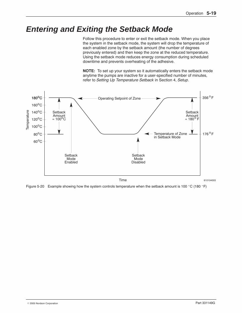
Operation 5-19
Part 331149G� 2005 Nordson Corporation
Entering and Exiting the Setback Mode Follow this procedure to enter or exit the setback mode. When you placethe system in the setback mode, the system will drop the temperature ofeach enabled zone by the setback amount (the number of degreespreviously entered) and then keep the zone at the reduced temperature.Using the setback mode reduces energy consumption during scheduleddowntime and prevents overheating of the adhesive.
NOTE: To set up your system so it automatically enters the setback modeanytime the pumps are inactive for a user-specified number of minutes,refer to Setting Up Temperature Setback in Section 4, Setup.
610104003
Operating Setpoint of Zone180 C
160 C
140 C
120 C
100 C
80 C
60 C
Tem
pera
ture
Time
SetbackAmount= 100 C
SetbackMode
Enabled
SetbackMode
Disabled
Temperature of Zonein Setback Mode
o
o
o
o
o
o
o
o
SetbackAmount= 180 Fo
180 Co 356 Fo
176 Fo
Figure 5-20 Example showing how the system controls temperature when the setback amount is 100 �C (180 �F)
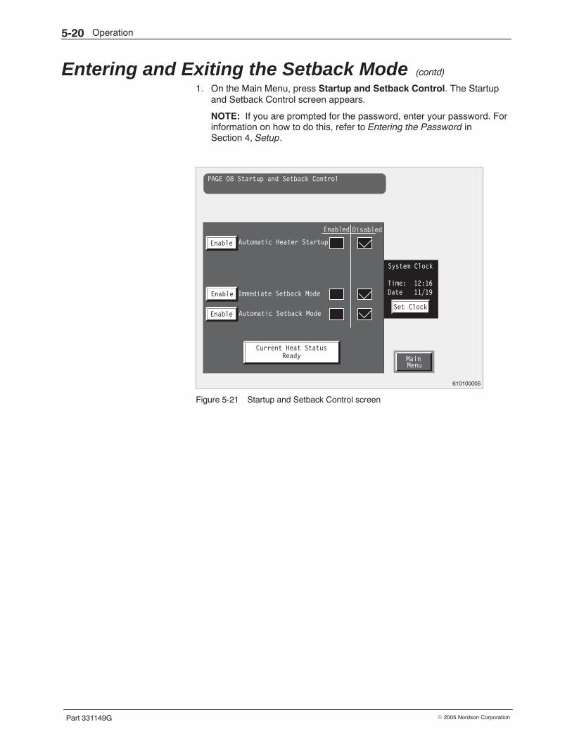
Operation5-20
Part 331149G � 2005 Nordson Corporation
Entering and Exiting the Setback Mode (contd)
1. On the Main Menu, press Startup and Setback Control. The Startupand Setback Control screen appears.
NOTE: If you are prompted for the password, enter your password. Forinformation on how to do this, refer to Entering the Password inSection 4, Setup.
MainMenu
PAGE 08 Startup and Setback Control
Automatic Heater Startup
Enabled Disabled
Enable
Immediate Setback Mode
Automatic Setback Mode
Enable
Enable
Current Heat StatusReady
Set Clock
System Clock
Time: 12:16Date 11/19
610100005
Figure 5-21 Startup and Setback Control screen
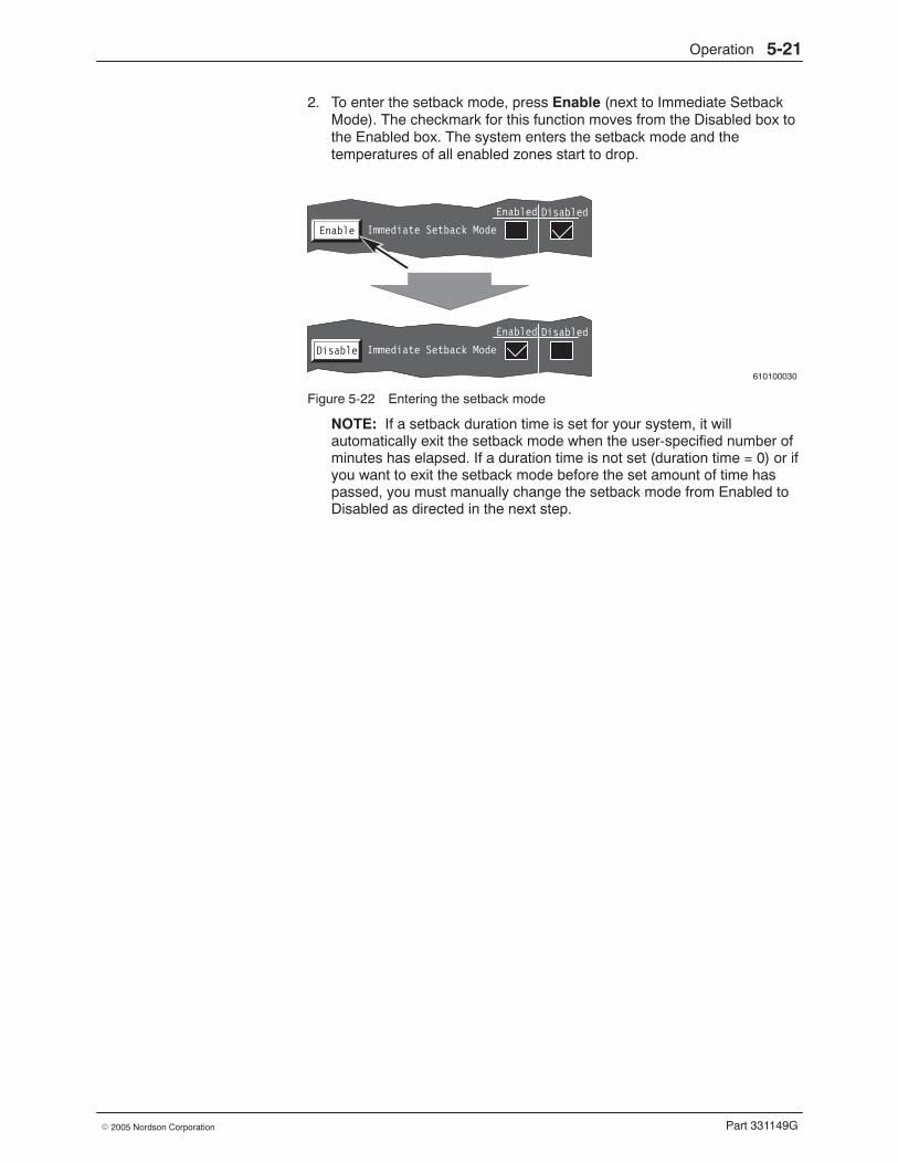
Operation 5-21
Part 331149G� 2005 Nordson Corporation
2. To enter the setback mode, press Enable (next to Immediate SetbackMode). The checkmark for this function moves from the Disabled box tothe Enabled box. The system enters the setback mode and thetemperatures of all enabled zones start to drop.
610100030
Enabled Disabled
Immediate Setback ModeEnable
Enabled Disabled
Immediate Setback ModeDisable
Figure 5-22 Entering the setback mode
NOTE: If a setback duration time is set for your system, it willautomatically exit the setback mode when the user-specified number ofminutes has elapsed. If a duration time is not set (duration time = 0) or ifyou want to exit the setback mode before the set amount of time haspassed, you must manually change the setback mode from Enabled toDisabled as directed in the next step.
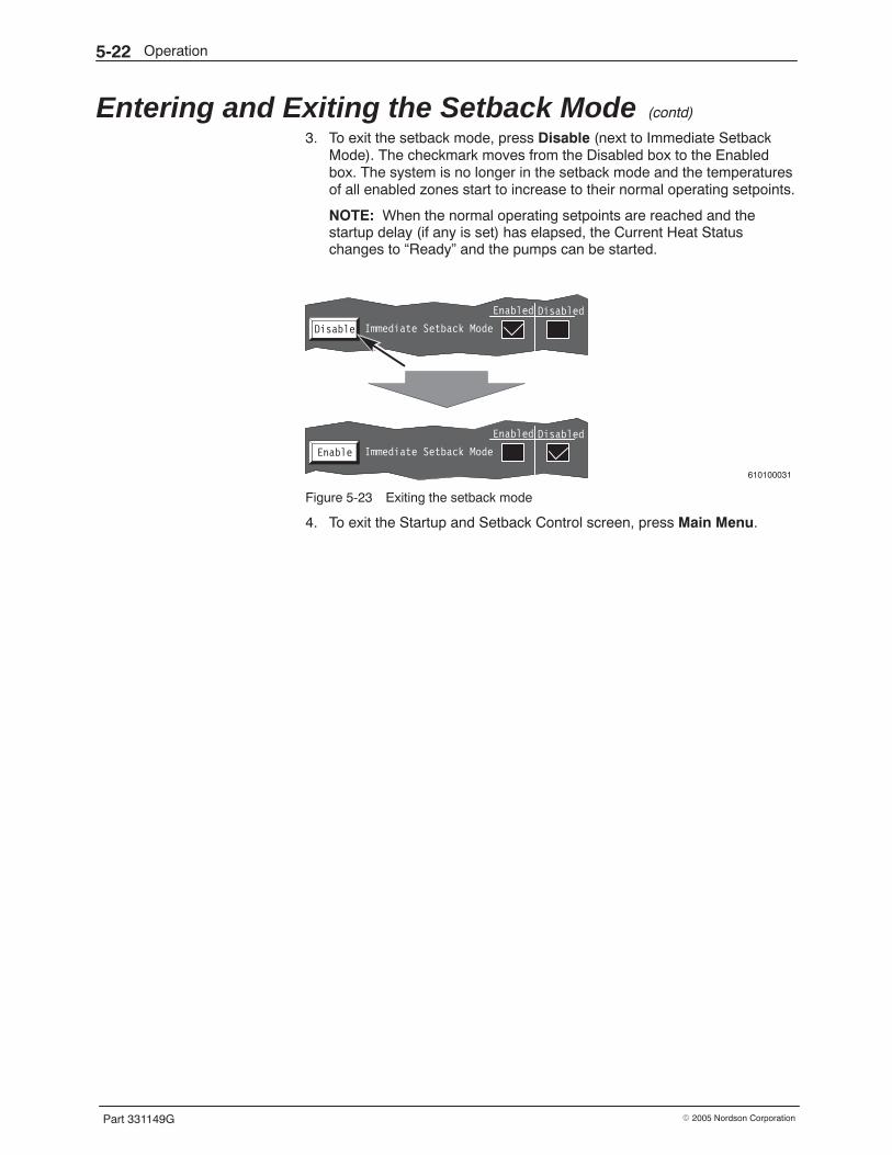
Operation5-22
Part 331149G � 2005 Nordson Corporation
Entering and Exiting the Setback Mode (contd)
3. To exit the setback mode, press Disable (next to Immediate SetbackMode). The checkmark moves from the Disabled box to the Enabledbox. The system is no longer in the setback mode and the temperaturesof all enabled zones start to increase to their normal operating setpoints.
NOTE: When the normal operating setpoints are reached and thestartup delay (if any is set) has elapsed, the Current Heat Statuschanges to “Ready” and the pumps can be started.
610100031
Enabled Disabled
Immediate Setback ModeEnable
Enabled Disabled
Immediate Setback ModeDisable
Figure 5-23 Exiting the setback mode
4. To exit the Startup and Setback Control screen, press Main Menu.
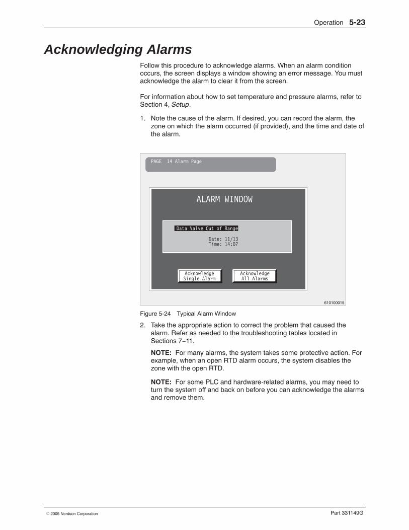
Operation 5-23
Part 331149G� 2005 Nordson Corporation
Acknowledging Alarms Follow this procedure to acknowledge alarms. When an alarm conditionoccurs, the screen displays a window showing an error message. You mustacknowledge the alarm to clear it from the screen.
For information about how to set temperature and pressure alarms, refer toSection 4, Setup.
1. Note the cause of the alarm. If desired, you can record the alarm, thezone on which the alarm occurred (if provided), and the time and date ofthe alarm.
PAGE 14 Alarm Page
ALARM WINDOW
Date: 11/13Time: 14:07
AcknowledgeSingle Alarm
AcknowledgeAll Alarms
Data Valve Out of Range
610100015
Figure 5-24 Typical Alarm Window
2. Take the appropriate action to correct the problem that caused thealarm. Refer as needed to the troubleshooting tables located inSections 7−11.
NOTE: For many alarms, the system takes some protective action. Forexample, when an open RTD alarm occurs, the system disables thezone with the open RTD.
NOTE: For some PLC and hardware-related alarms, you may need toturn the system off and back on before you can acknowledge the alarmsand remove them.
Operation5-24
Part 331149G � 2005 Nordson Corporation
Acknowledging Alarms (contd)
3. Acknowledge the alarm in one of the following two ways:
� To acknowledge only the alarm shown on the screen, pressAcknowledge Single Alarm. This action adds the alarm to the listof the last ten alarms that you can view.
� To acknowledge the alarm shown on the screen plus any otheralarms that may exist, press Acknowledge All Alarms. This actionadds the displayed alarm to the list of the last ten alarms that youcan view but does not add any additional alarms that may exist.
4. When you have acknowledged all existing alarms, the alarm window willbe removed from the screen.
5. To view the last ten alarms, display the Main Menu and then pressConfiguration Page. On the Main Configuration Menu, press View LastTen Alarms.
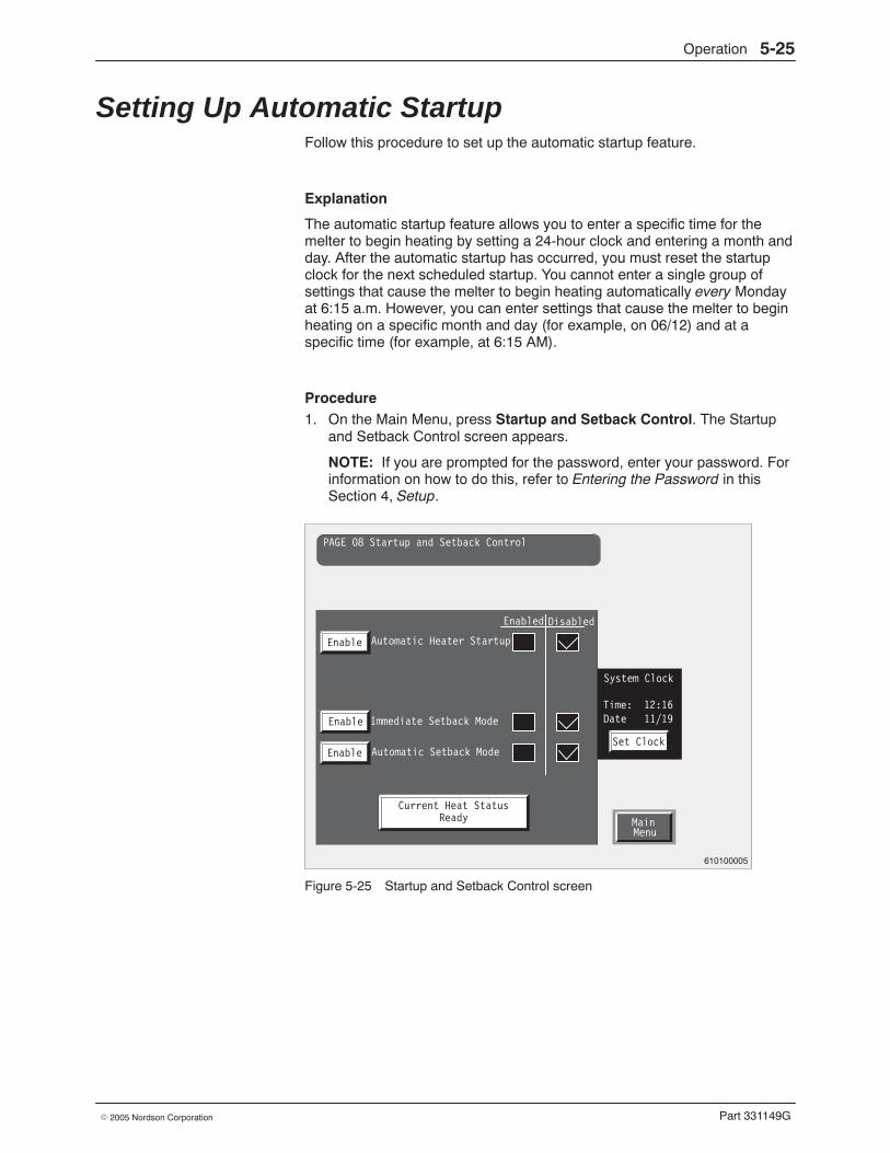
Operation 5-25
Part 331149G� 2005 Nordson Corporation
Setting Up Automatic Startup Follow this procedure to set up the automatic startup feature.
Explanation
The automatic startup feature allows you to enter a specific time for themelter to begin heating by setting a 24-hour clock and entering a month andday. After the automatic startup has occurred, you must reset the startupclock for the next scheduled startup. You cannot enter a single group ofsettings that cause the melter to begin heating automatically every Mondayat 6:15 a.m. However, you can enter settings that cause the melter to beginheating on a specific month and day (for example, on 06/12) and at aspecific time (for example, at 6:15 AM).
Procedure 1. On the Main Menu, press Startup and Setback Control. The Startup
and Setback Control screen appears.
NOTE: If you are prompted for the password, enter your password. Forinformation on how to do this, refer to Entering the Password in thisSection 4, Setup.
MainMenu
PAGE 08 Startup and Setback Control
Automatic Heater Startup
Enabled Disabled
Enable
Immediate Setback Mode
Automatic Setback Mode
Enable
Enable
Current Heat StatusReady
Set Clock
System Clock
Time: 12:16Date 11/19
610100005
Figure 5-25 Startup and Setback Control screen
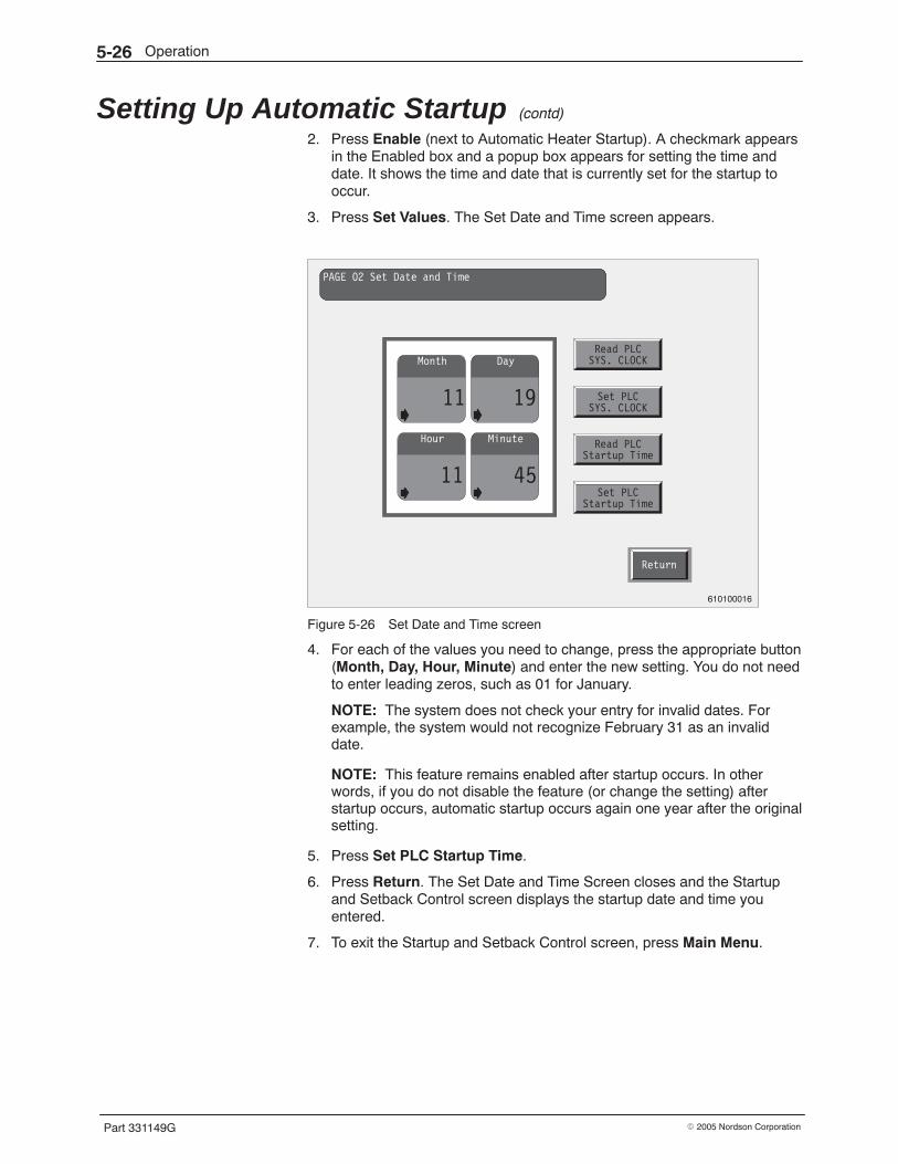
Operation5-26
Part 331149G � 2005 Nordson Corporation
Setting Up Automatic Startup (contd)
2. Press Enable (next to Automatic Heater Startup). A checkmark appearsin the Enabled box and a popup box appears for setting the time anddate. It shows the time and date that is currently set for the startup tooccur.
3. Press Set Values. The Set Date and Time screen appears.
Return
PAGE 02 Set Date and Time
Month
11
Day
19
Hour
11
Minute
45
Read PLCSYS. CLOCK
Set PLCSYS. CLOCK
Read PLCStartup Time
Set PLCStartup Time
610100016
Figure 5-26 Set Date and Time screen
4. For each of the values you need to change, press the appropriate button(Month, Day, Hour, Minute) and enter the new setting. You do not needto enter leading zeros, such as 01 for January.
NOTE: The system does not check your entry for invalid dates. Forexample, the system would not recognize February 31 as an invaliddate.
NOTE: This feature remains enabled after startup occurs. In otherwords, if you do not disable the feature (or change the setting) afterstartup occurs, automatic startup occurs again one year after the originalsetting.
5. Press Set PLC Startup Time.
6. Press Return. The Set Date and Time Screen closes and the Startupand Setback Control screen displays the startup date and time youentered.
7. To exit the Startup and Setback Control screen, press Main Menu.
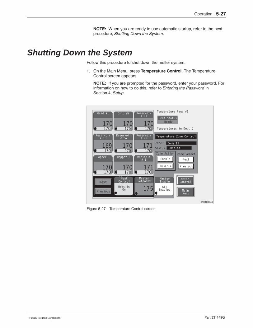
Operation 5-27
Part 331149G� 2005 Nordson Corporation
NOTE: When you are ready to use automatic startup, refer to the nextprocedure, Shutting Down the System.
Shutting Down the System Follow this procedure to shut down the melter system.
1. On the Main Menu, press Temperature Control. The TemperatureControl screen appears.
NOTE: If you are prompted for the password, enter your password. Forinformation on how to do this, refer to Entering the Password inSection 4, Setup.
Heat Status
Zone:
Status:
AllEnabled
Zone 13
Enabled
Temperature Zone Control
MasterEnable
MotorControl
MainMenu
Zone Action
Enable
Disable
Next
Previous
Zone Select
Next
170170
Temperature Page #1
Ready
Temperatures in Deg. C
Heat isOn
HeatControlHeat is
On
HeatControl
Grid #1 Grid #2
170170
Manifold
171170
# 1Hopper 2
170170
Hopper 1
170170
Reservoir
169170
# 1BReservoir
170170
# 2AReservoir
171170
# 2B
Reservoir
170170
# 1A
Master
175
Setpoint
Zone Action
Enable
Disable
PreviousPrevious
610100045
Figure 5-27 Temperature Control screen
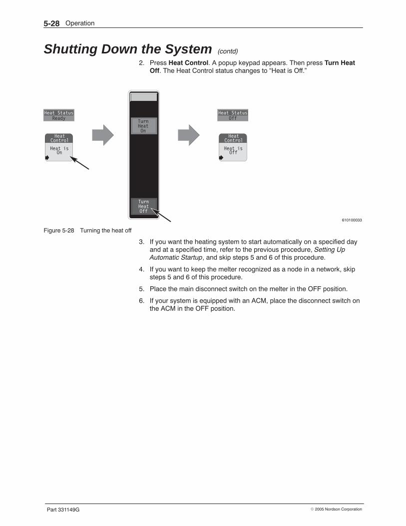
Operation5-28
Part 331149G � 2005 Nordson Corporation
Shutting Down the System (contd)
2. Press Heat Control. A popup keypad appears. Then press Turn HeatOff. The Heat Control status changes to “Heat is Off.”
610100033
Heat isOn
HeatControl
Heat StatusReady
Heat isOff
HeatControl
Heat StatusOff
TurnHeatOn
TurnHeatOff
Figure 5-28 Turning the heat off
3. If you want the heating system to start automatically on a specified dayand at a specified time, refer to the previous procedure, Setting UpAutomatic Startup, and skip steps 5 and 6 of this procedure.
4. If you want to keep the melter recognized as a node in a network, skipsteps 5 and 6 of this procedure.
5. Place the main disconnect switch on the melter in the OFF position.
6. If your system is equipped with an ACM, place the disconnect switch onthe ACM in the OFF position.
Maintenance 6-1
Part 331149G� 2005 Nordson Corporation
Section 6Maintenance
WARNING: Allow only personnel with appropriate training and experienceto operate or service the equipment. The use of untrained or inexperiencedpersonnel to operate or service the equipment can result in injury, includingdeath, to themselves and others, and damage to the equipment.
Introduction Performing routine maintenance can extend the life of the melter anddecrease downtime. This section provides a schedule of recommendedmaintenance activities and some maintenance procedures. Beforeperforming any maintenance procedures, review Section 1, Safety.
WARNING: Attempting any other maintenance procedures can result inequipment damage, improper system operation, or personal injury.
Required Tools and Supplies To perform maintenance or repairs, you will need:
� a set of metric socket wrenches� a set of metric Allen (hex) wrenches� a set of metric T-handle hex keys� a set of metric open-ended wrenches� flat-blade and Phillips-head screwdrivers� drain pans and large waste containers� other tools as noted
You will also need a sufficient inventory of spare parts and supplies. Eachprocedure is preceded by a list of the parts and supplies you will need.Refer to Section 12, Parts, for the part numbers for all parts and supplies.
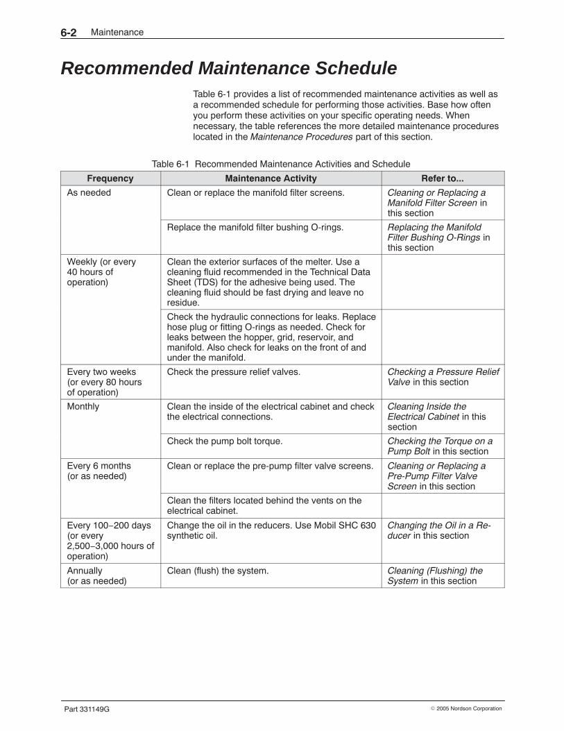
Maintenance6-2
Part 331149G � 2005 Nordson Corporation
Recommended Maintenance Schedule Table 6-1 provides a list of recommended maintenance activities as well asa recommended schedule for performing those activities. Base how oftenyou perform these activities on your specific operating needs. Whennecessary, the table references the more detailed maintenance procedureslocated in the Maintenance Procedures part of this section.
Table 6-1 Recommended Maintenance Activities and Schedule
Frequency Maintenance Activity Refer to...
As needed Clean or replace the manifold filter screens. Cleaning or Replacing aManifold Filter Screen inthis section
Replace the manifold filter bushing O-rings. Replacing the ManifoldFilter Bushing O-Rings inthis section
Weekly (or every40 hours ofoperation)
Clean the exterior surfaces of the melter. Use acleaning fluid recommended in the Technical DataSheet (TDS) for the adhesive being used. Thecleaning fluid should be fast drying and leave noresidue.
Check the hydraulic connections for leaks. Replacehose plug or fitting O-rings as needed. Check forleaks between the hopper, grid, reservoir, andmanifold. Also check for leaks on the front of andunder the manifold.
Every two weeks(or every 80 hoursof operation)
Check the pressure relief valves. Checking a Pressure ReliefValve in this section
Monthly Clean the inside of the electrical cabinet and checkthe electrical connections.
Cleaning Inside theElectrical Cabinet in thissection
Check the pump bolt torque. Checking the Torque on aPump Bolt in this section
Every 6 months(or as needed)
Clean or replace the pre-pump filter valve screens. Cleaning or Replacing aPre-Pump Filter ValveScreen in this section
Clean the filters located behind the vents on theelectrical cabinet.
Every 100−200 days(or every2,500−3,000 hours ofoperation)
Change the oil in the reducers. Use Mobil SHC 630synthetic oil.
Changing the Oil in a Re-ducer in this section
Annually(or as needed)
Clean (flush) the system. Cleaning (Flushing) theSystem in this section
Maintenance 6-3
Part 331149G� 2005 Nordson Corporation
Preparation for Maintenance Activities To safely perform many of the maintenance, troubleshooting, and repairprocedures in this manual, you may need to perform one or more of thefollowing procedures:
� removing power� relieving system pressure� removing a panel� closing a pre-pump filter valve� draining the system
Refer to these procedures as noted throughout this manual.
WARNING: To service any part of the mechanical system that containsadhesive, you should start with the system warm or hot. Some proceduresrequire the adhesive to be at least at its softening point. Others require it tobe at application temperature. To protect yourself from burns caused by hotadhesive and metal surfaces, service the equipment with the adhesive atthe lowest temperature possible.
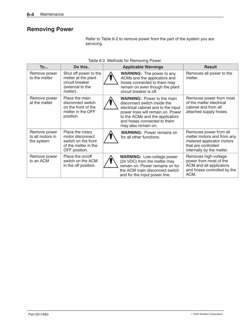
Maintenance6-4
Part 331149G � 2005 Nordson Corporation
Removing Power
Refer to Table 6-2 to remove power from the part of the system you areservicing.
Table 6-2 Methods for Removing Power
To... Do this.. Applicable Warnings Result
Remove powerto the melter
Shut off power to themelter at the plantcircuit breaker(external to themelter).
WARNING: The power to anyACMs and the applicators andhoses connected to them mayremain on even though the plantcircuit breaker is off.
Removes all power to themelter.
Remove powerat the melter
Place the maindisconnect switchon the front of themelter in the OFFposition.
WARNING: Power to the maindisconnect switch inside theelectrical cabinet and to the inputpower lines will remain on. Powerto the ACMs and the applicatorsand hoses connected to themmay also remain on.
Removes power from mostof the melter electricalcabinet and from allattached supply hoses.
Remove powerto all motors inthe system
Place the rotarymotor disconnectswitch on the frontof the melter in theOFF position.
WARNING: Power remains onfor all other functions.
Removes power from allmelter motors and from anymetered applicator motorsthat are controlledinternally by the melter.
Remove powerto an ACM
Place the on/offswitch on the ACMin the off position.
WARNING: Low-voltage power(24 VDC) from the melter mayremain on. Power remains on forthe ACM main disconnect switchand for the input power line.
Removes high-voltagepower from most of theACM and all applicatorsand hoses controlled by theACM.
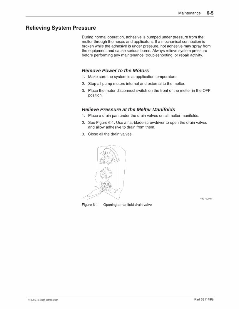
Maintenance 6-5
Part 331149G� 2005 Nordson Corporation
Relieving System Pressure
During normal operation, adhesive is pumped under pressure from themelter through the hoses and applicators. If a mechanical connection isbroken while the adhesive is under pressure, hot adhesive may spray fromthe equipment and cause serious burns. Always relieve system pressurebefore performing any maintenance, troubleshooting, or repair activity.
Remove Power to the Motors 1. Make sure the system is at application temperature.
2. Stop all pump motors internal and external to the melter.
3. Place the motor disconnect switch on the front of the melter in the OFFposition.
Relieve Pressure at the Melter Manifolds 1. Place a drain pan under the drain valves on all melter manifolds.
2. See Figure 6-1. Use a flat-blade screwdriver to open the drain valvesand allow adhesive to drain from them.
3. Close all the drain valves.
410100004
Figure 6-1 Opening a manifold drain valve
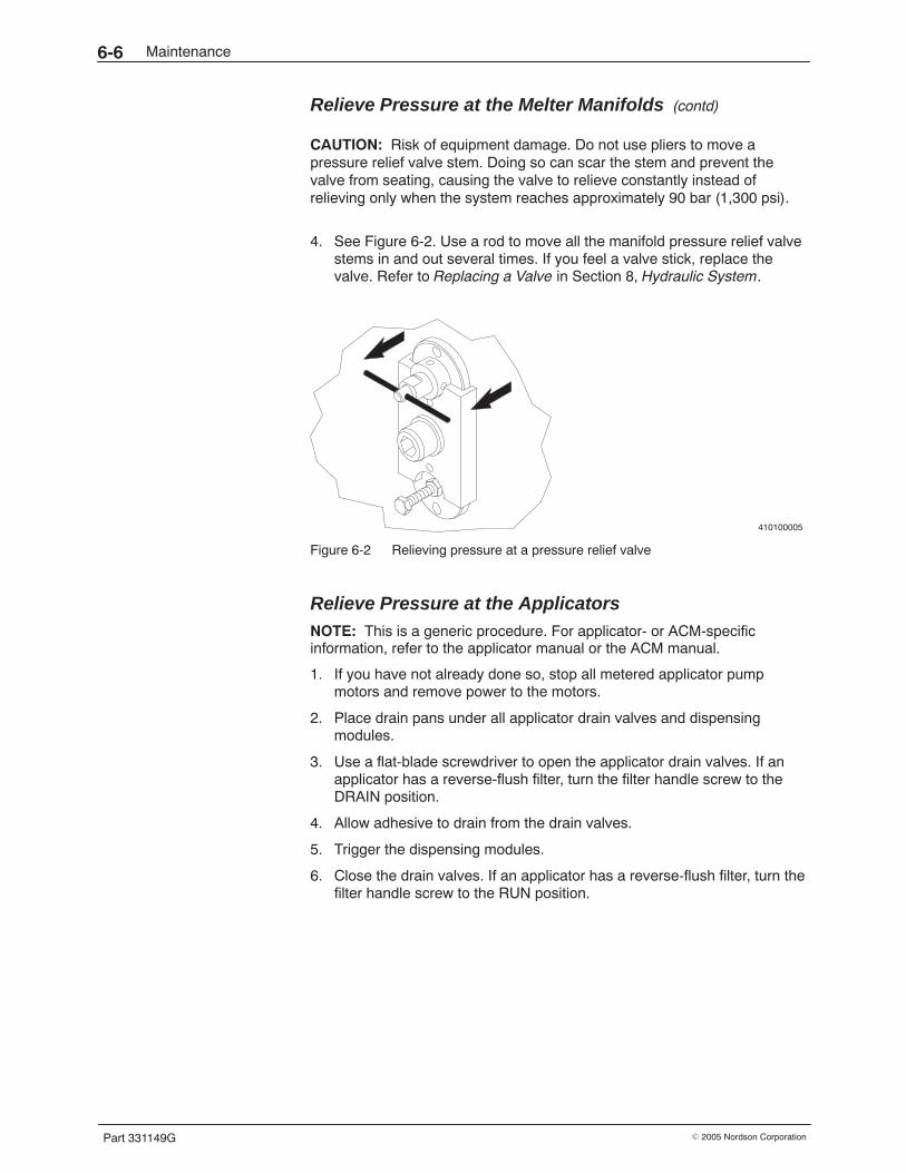
Maintenance6-6
Part 331149G � 2005 Nordson Corporation
Relieve Pressure at the Melter Manifolds (contd)
CAUTION: Risk of equipment damage. Do not use pliers to move apressure relief valve stem. Doing so can scar the stem and prevent thevalve from seating, causing the valve to relieve constantly instead ofrelieving only when the system reaches approximately 90 bar (1,300 psi).
4. See Figure 6-2. Use a rod to move all the manifold pressure relief valvestems in and out several times. If you feel a valve stick, replace thevalve. Refer to Replacing a Valve in Section 8, Hydraulic System.
410100005
Figure 6-2 Relieving pressure at a pressure relief valve
Relieve Pressure at the Applicators NOTE: This is a generic procedure. For applicator- or ACM-specificinformation, refer to the applicator manual or the ACM manual.
1. If you have not already done so, stop all metered applicator pumpmotors and remove power to the motors.
2. Place drain pans under all applicator drain valves and dispensingmodules.
3. Use a flat-blade screwdriver to open the applicator drain valves. If anapplicator has a reverse-flush filter, turn the filter handle screw to theDRAIN position.
4. Allow adhesive to drain from the drain valves.
5. Trigger the dispensing modules.
6. Close the drain valves. If an applicator has a reverse-flush filter, turn thefilter handle screw to the RUN position.
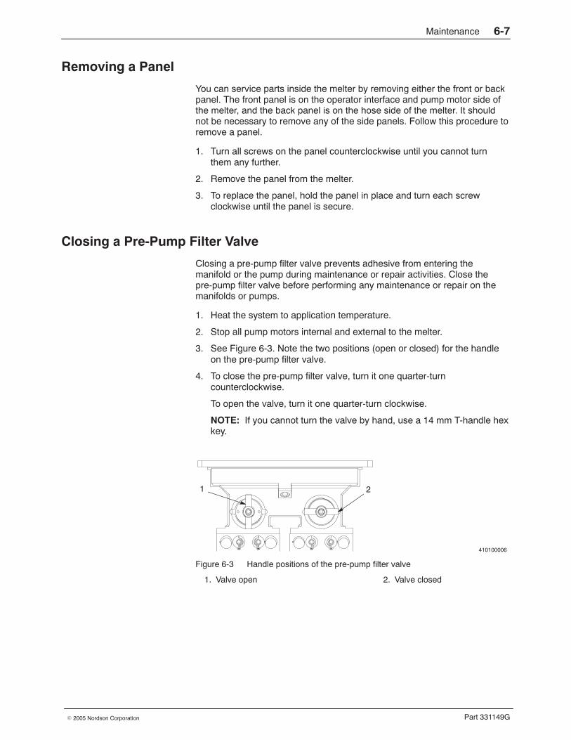
Maintenance 6-7
Part 331149G� 2005 Nordson Corporation
Removing a Panel
You can service parts inside the melter by removing either the front or backpanel. The front panel is on the operator interface and pump motor side ofthe melter, and the back panel is on the hose side of the melter. It shouldnot be necessary to remove any of the side panels. Follow this procedure toremove a panel.
1. Turn all screws on the panel counterclockwise until you cannot turnthem any further.
2. Remove the panel from the melter.
3. To replace the panel, hold the panel in place and turn each screwclockwise until the panel is secure.
Closing a Pre-Pump Filter Valve
Closing a pre-pump filter valve prevents adhesive from entering themanifold or the pump during maintenance or repair activities. Close thepre-pump filter valve before performing any maintenance or repair on themanifolds or pumps.
1. Heat the system to application temperature.
2. Stop all pump motors internal and external to the melter.
3. See Figure 6-3. Note the two positions (open or closed) for the handleon the pre-pump filter valve.
4. To close the pre-pump filter valve, turn it one quarter-turncounterclockwise.
To open the valve, turn it one quarter-turn clockwise.
NOTE: If you cannot turn the valve by hand, use a 14 mm T-handle hexkey.
410100006
1 2
Figure 6-3 Handle positions of the pre-pump filter valve
1. Valve open 2. Valve closed
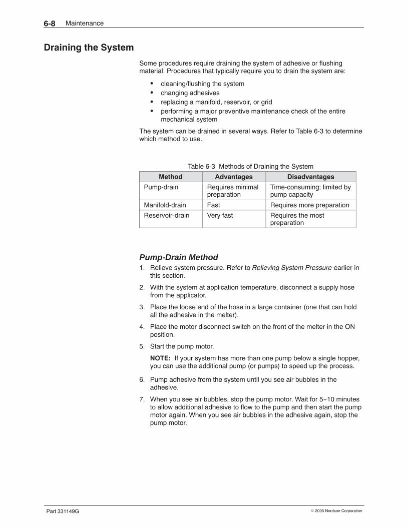
Maintenance6-8
Part 331149G � 2005 Nordson Corporation
Draining the System
Some procedures require draining the system of adhesive or flushingmaterial. Procedures that typically require you to drain the system are:
� cleaning/flushing the system� changing adhesives� replacing a manifold, reservoir, or grid� performing a major preventive maintenance check of the entire
mechanical system
The system can be drained in several ways. Refer to Table 6-3 to determinewhich method to use.
Table 6-3 Methods of Draining the System
Method Advantages Disadvantages
Pump-drain Requires minimalpreparation
Time-consuming; limited bypump capacity
Manifold-drain Fast Requires more preparation
Reservoir-drain Very fast Requires the mostpreparation
Pump-Drain Method 1. Relieve system pressure. Refer to Relieving System Pressure earlier in
this section.
2. With the system at application temperature, disconnect a supply hosefrom the applicator.
3. Place the loose end of the hose in a large container (one that can holdall the adhesive in the melter).
4. Place the motor disconnect switch on the front of the melter in the ONposition.
5. Start the pump motor.
NOTE: If your system has more than one pump below a single hopper,you can use the additional pump (or pumps) to speed up the process.
6. Pump adhesive from the system until you see air bubbles in theadhesive.
7. When you see air bubbles, stop the pump motor. Wait for 5−10 minutesto allow additional adhesive to flow to the pump and then start the pumpmotor again. When you see air bubbles in the adhesive again, stop thepump motor.
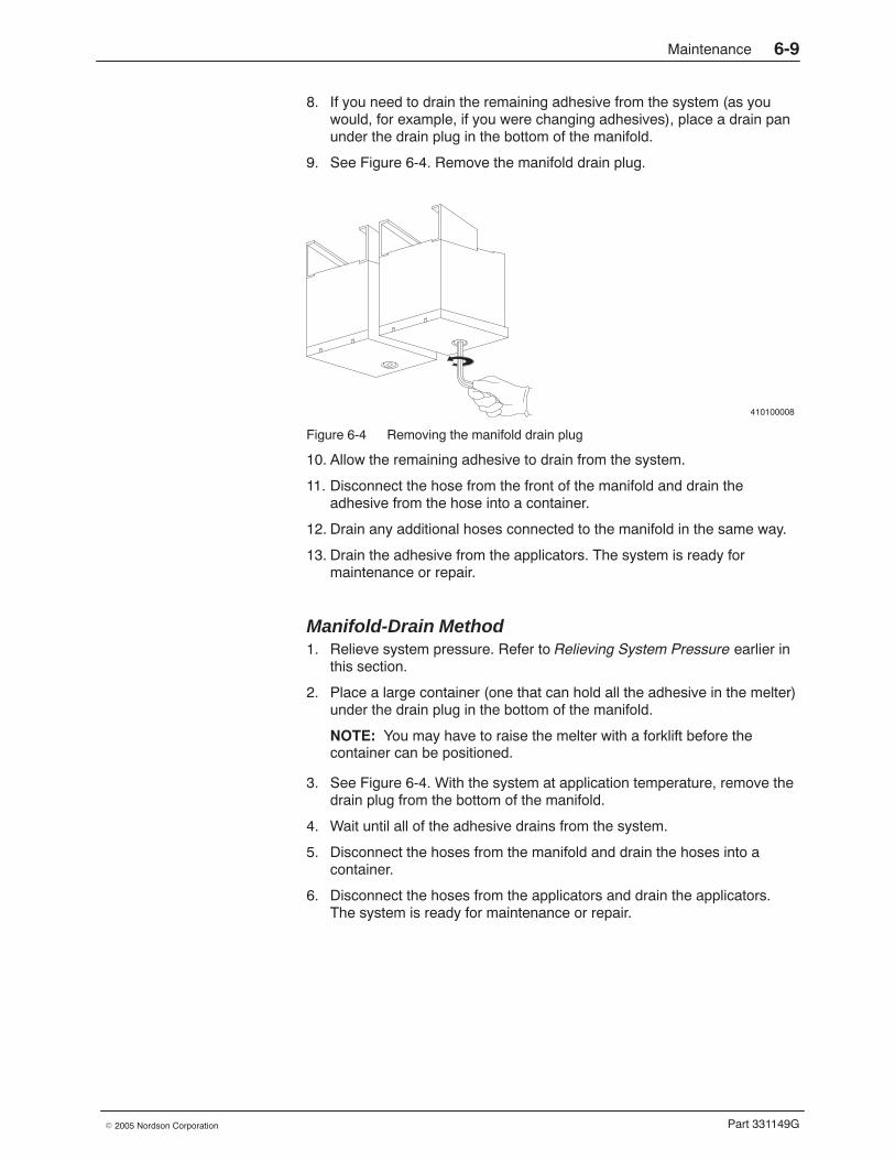
Maintenance 6-9
Part 331149G� 2005 Nordson Corporation
8. If you need to drain the remaining adhesive from the system (as youwould, for example, if you were changing adhesives), place a drain panunder the drain plug in the bottom of the manifold.
9. See Figure 6-4. Remove the manifold drain plug.
410100008
Figure 6-4 Removing the manifold drain plug
10. Allow the remaining adhesive to drain from the system.
11. Disconnect the hose from the front of the manifold and drain theadhesive from the hose into a container.
12. Drain any additional hoses connected to the manifold in the same way.
13. Drain the adhesive from the applicators. The system is ready formaintenance or repair.
Manifold-Drain Method 1. Relieve system pressure. Refer to Relieving System Pressure earlier in
this section.
2. Place a large container (one that can hold all the adhesive in the melter)under the drain plug in the bottom of the manifold.
NOTE: You may have to raise the melter with a forklift before thecontainer can be positioned.
3. See Figure 6-4. With the system at application temperature, remove thedrain plug from the bottom of the manifold.
4. Wait until all of the adhesive drains from the system.
5. Disconnect the hoses from the manifold and drain the hoses into acontainer.
6. Disconnect the hoses from the applicators and drain the applicators.The system is ready for maintenance or repair.
Maintenance6-10
Part 331149G � 2005 Nordson Corporation
Reservoir-Drain Method 1. Relieve system pressure. Refer to Relieving System Pressure earlier in
this section.
2. Place a large container (one that can hold all the adhesive in the melter)under the bottom of the manifold.
NOTE: You may have to raise the melter with a forklift before thecontainer can be positioned.
3. With the system at application temperature, close the pre-pump filtervalve by turning it one quarter-turn counterclockwise.
NOTE: You may want to drain the adhesive from the manifold toprevent the adhesive from solidifying in the manifold after the manifold isremoved. If so, refer to the previous procedure, Manifold-Drain Method.
4. Remove the manifold. Refer to Remove the Manifold in Section 8,Hydraulic System.
5. Turn the pre-pump valve one-quarter turn clockwise to open the valve.
6. Allow all of the adhesive to drain from the system.
7. Disconnect the hoses from the applicators and drain the applicators.
The system is ready for maintenance or repair.
Maintenance 6-11
Part 331149G� 2005 Nordson Corporation
Maintenance Procedures Perform these maintenance procedures as needed or as recommended inTable 6-1.
Cleaning or Replacing a Manifold Filter Screen Clean or replace the manifold filter screen(s) as needed. Cleaning the filterscreens prevents char and debris from clogging the filters and reducing theflow of adhesive through the system. If, as you are performing thisprocedure, you notice that a filter screen is damaged, replace it. You willneed the following items to perform this procedure:
� drain pan� appropriate tools, including a T-handle hex key� cleaning supplies (if needed, refer to the melter manual)� replacement filter screen (if needed)� replacement O-ring� O-ring lubricant� anti-seize lubricant
NOTE: To prevent downtime, Nordson Corporation recommendsmaintaining at least two complete filter assemblies so that a clean filterassembly can be installed and used while the dirty filter screen is beingcleaned.
NOTE: If you are cleaning melter and applicator filter screens at the sametime, clean the melter filter screens first.
CAUTION: See Figure 6-5. Remove only the manifold filter when cleaningor replacing a filter screen—do not remove the filter bushing or retainer.Doing so could damage the seal and result in leakage.
12
Figure 6-5 Correct and incorrect methods for removing a filter
1. Filter removed 2. Filter and bushing removed
Maintenance6-12
Part 331149G � 2005 Nordson Corporation
Remove the Manifold Filter 1. Relieve system pressure. Refer to Relieving System Pressure in the
melter manual as needed
2. See Figure 6-6. Use a T-handle hex key to turn the filtercounterclockwise to loosen it and then pull the filter straight out of themanifold over a drain pan.
Figure 6-6 Removing a manifold filter
3. Wipe any spilled adhesive from the manifold and from the front of thefilter cavity.
NOTE: To return to operation immediately, install a spare filter. Refer toInstall the Manifold Filter later in this procedure.
Clean the Manifold Filter Screen 1. See Figure 6-7. Disassemble the filter.
ÂÂÂÂÂÂ
1
2
3
4
Figure 6-7 Manifold filter components
1. Bung2. O-ring
3. Filter screen4. End cap
Maintenance 6-13
Part 331149G� 2005 Nordson Corporation
2. Inspect the filter screen (3). If there are any dents, tears, or blockages inthe screen, obtain a new screen and skip to step 4.
3. If the filter screen is not damaged, refer to Cleaning Parts in the meltermanual to clean the screen.
4. Apply O-ring lubricant to a new O-ring (2) and reassemble the filter.
5. Apply anti-seize lubricant to the filter threads.
Install the Manifold Filter 1. Make sure the system is at application temperature.
CAUTION: Risk of equipment damage. To prevent damage to the filterscreen, the system must be at application temperature when the filter isreinstalled.
2. Push the filter into the manifold until it stops.
3. Use a T-handle hex key to turn the filter clockwise to secure it.
4. Use one of the following methods to purge air from the adhesive streamfor which the filter screen was cleaned or replaced:
� Remove the supply hose fitting and allow adhesive to drain from thehose port until the air is purged (this is the quickest method).
� Open the drain valve of the applicator that the adhesive streamsupplies and allow adhesive to drain from the applicator until the airis purged.
Maintenance6-14
Part 331149G � 2005 Nordson Corporation
Replacing the Manifold Filter Bushing O-Rings
Replace the manifold filter bushing O-rings as needed. You will need thefollowing items to perform this procedure:
� drain pan� appropriate tools, including a T-handle hex key� replacement O-rings� O-ring lubricant
1. Relieve system pressure. Refer to Relieving System Pressure in themelter manual as needed.
2. Heat the system until the manifold is above the melting temperature ofthe adhesive and then drain the manifold. Refer to Draining the Systemin the melter manual as needed.
3. See Figure 6-8. Use an 8-mm T-handle hex key to loosen the manifoldfilter (2).
4. Use a 5-mm hex wrench to remove the bushing retainer (1).
5. Remove the manifold filter and bushing (2, 3).
6. Remove the damaged O-rings (4) from the bushing and clean anydebris out of the grooves.
7. Lubricate new O-rings and install them in the grooves.
8. Insert the filter and bushing in the the filter bore.
9. With the filter threads loose (to ensure that the retainer will not interferewith the filter top), insert the bushing in the filter bore and hold it in thisposition until the solid adhesive caught in the O-ring gland has melted.
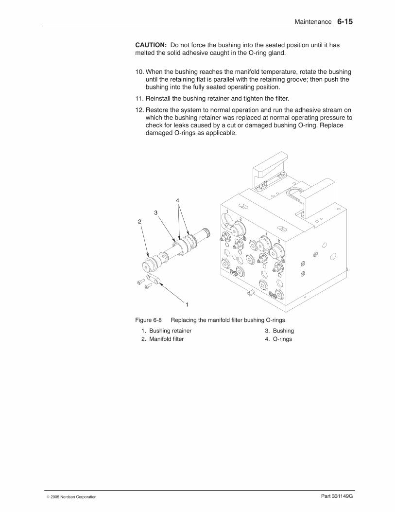
Maintenance 6-15
Part 331149G� 2005 Nordson Corporation
CAUTION: Do not force the bushing into the seated position until it hasmelted the solid adhesive caught in the O-ring gland.
10. When the bushing reaches the manifold temperature, rotate the bushinguntil the retaining flat is parallel with the retaining groove; then push thebushing into the fully seated operating position.
11. Reinstall the bushing retainer and tighten the filter.
12. Restore the system to normal operation and run the adhesive stream onwhich the bushing retainer was replaced at normal operating pressure tocheck for leaks caused by a cut or damaged bushing O-ring. Replacedamaged O-rings as applicable.
4
3
1
2
Figure 6-8 Replacing the manifold filter bushing O-rings
1. Bushing retainer2. Manifold filter
3. Bushing4. O-rings
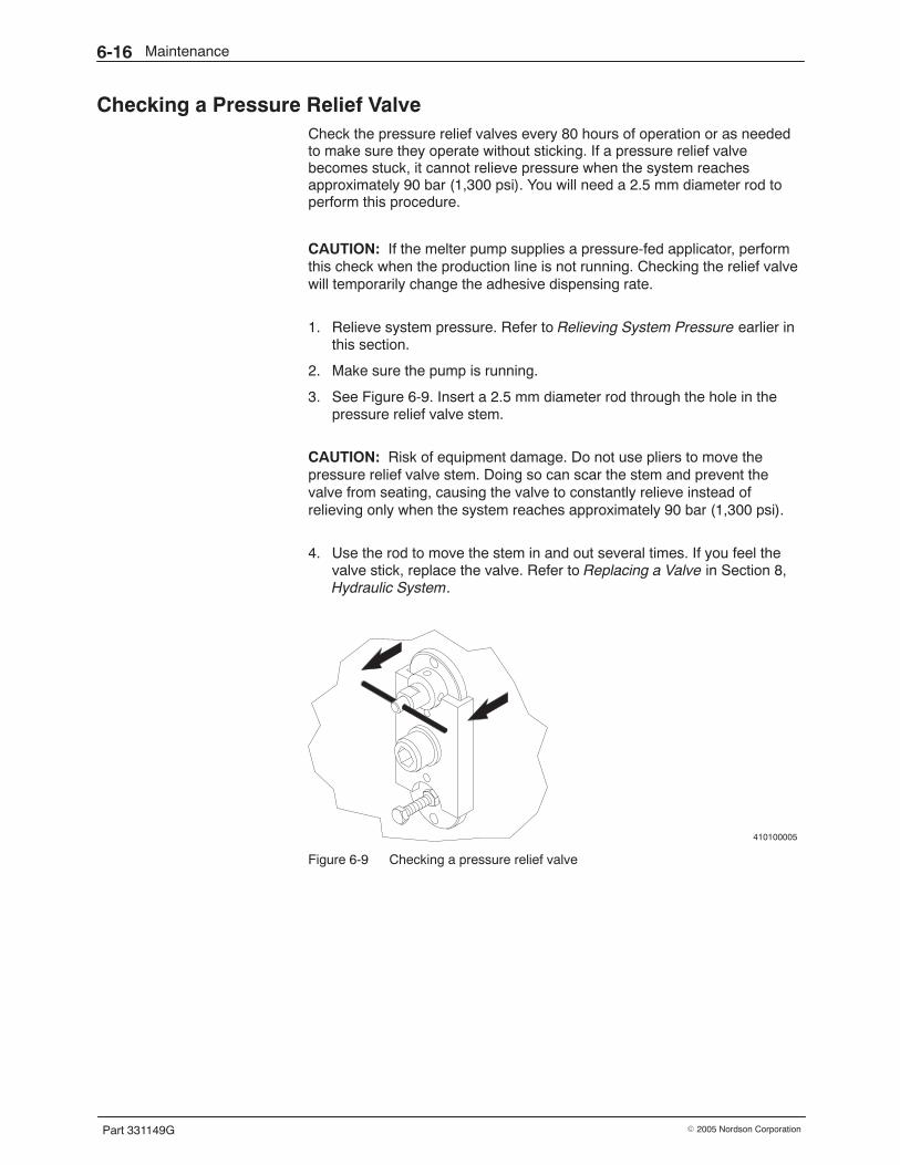
Maintenance6-16
Part 331149G � 2005 Nordson Corporation
Checking a Pressure Relief Valve Check the pressure relief valves every 80 hours of operation or as neededto make sure they operate without sticking. If a pressure relief valvebecomes stuck, it cannot relieve pressure when the system reachesapproximately 90 bar (1,300 psi). You will need a 2.5 mm diameter rod toperform this procedure.
CAUTION: If the melter pump supplies a pressure-fed applicator, performthis check when the production line is not running. Checking the relief valvewill temporarily change the adhesive dispensing rate.
1. Relieve system pressure. Refer to Relieving System Pressure earlier inthis section.
2. Make sure the pump is running.
3. See Figure 6-9. Insert a 2.5 mm diameter rod through the hole in thepressure relief valve stem.
CAUTION: Risk of equipment damage. Do not use pliers to move thepressure relief valve stem. Doing so can scar the stem and prevent thevalve from seating, causing the valve to constantly relieve instead ofrelieving only when the system reaches approximately 90 bar (1,300 psi).
4. Use the rod to move the stem in and out several times. If you feel thevalve stick, replace the valve. Refer to Replacing a Valve in Section 8,Hydraulic System.
410100005
Figure 6-9 Checking a pressure relief valve
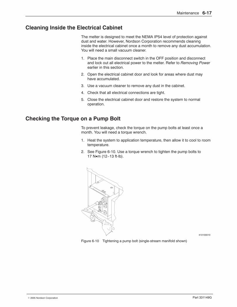
Maintenance 6-17
Part 331149G� 2005 Nordson Corporation
Cleaning Inside the Electrical Cabinet
The melter is designed to meet the NEMA IP54 level of protection againstdust and water. However, Nordson Corporation recommends cleaninginside the electrical cabinet once a month to remove any dust accumulation.You will need a small vacuum cleaner.
1. Place the main disconnect switch in the OFF position and disconnectand lock out all electrical power to the melter. Refer to Removing Powerearlier in this section.
2. Open the electrical cabinet door and look for areas where dust mayhave accumulated.
3. Use a vacuum cleaner to remove any dust in the cabinet.
4. Check that all electrical connections are tight.
5. Close the electrical cabinet door and restore the system to normaloperation.
Checking the Torque on a Pump Bolt
To prevent leakage, check the torque on the pump bolts at least once amonth. You will need a torque wrench.
1. Heat the system to application temperature, then allow it to cool to roomtemperature.
2. See Figure 6-10. Use a torque wrench to tighten the pump bolts to17 N•m (12−13 ft-lb).
410100010
Figure 6-10 Tightening a pump bolt (single-stream manifold shown)
Maintenance6-18
Part 331149G � 2005 Nordson Corporation
Cleaning or Replacing a Pre-Pump Filter Valve
Clean the pre-pump filter valve screen(s) every six months or as needed.Cleaning the filter screens prevents char and debris from clogging the filterand reducing the flow of adhesive through the system. If, as you areperforming this procedure, you notice that a filter screen is damaged,replace it. You will need the following items to perform this procedure:
� drain pan� appropriate tools� cleaning supplies (if needed, refer to Table 6-4)� replacement pre-pump filter valve screen (if needed)� replacement O-ring� O-ring lubricant
NOTE: To prevent downtime, Nordson Corporation recommendsmaintaining at least two complete filter valve assemblies so that a cleanfilter valve can be installed and used while the dirty filter screen is beingcleaned.
Remove the Pre-Pump Filter Valve 1. Relieve system pressure. Refer to Relieving System Pressure earlier in
this section.
2. Close the pre-pump filter valve. Refer to Closing a Pre-Pump FilterValve earlier in this section.
3. Pull the pre-pump filter valve straight out of the reservoir and hold it overa drain pan.
4. Wipe any spilled adhesive from the reservoir and filter cavity.
NOTE: To return to operation immediately, install a spare filter valve.Refer to Install the Pre-Pump Filter Valve later in this procedure.
Clean the Pre-Pump Filter Valve Screen 1. See Figure 6-11. Turn the filter upside down to let the screen fall out.
NOTE: If the screen is stuck, use a flat-blade screwdriver to pry it loose.
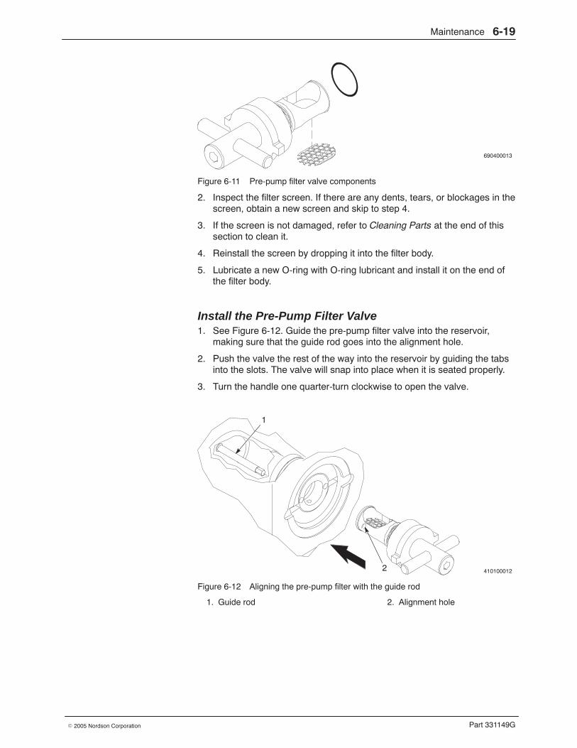
Maintenance 6-19
Part 331149G� 2005 Nordson Corporation
690400013
Figure 6-11 Pre-pump filter valve components
2. Inspect the filter screen. If there are any dents, tears, or blockages in thescreen, obtain a new screen and skip to step 4.
3. If the screen is not damaged, refer to Cleaning Parts at the end of thissection to clean it.
4. Reinstall the screen by dropping it into the filter body.
5. Lubricate a new O-ring with O-ring lubricant and install it on the end ofthe filter body.
Install the Pre-Pump Filter Valve 1. See Figure 6-12. Guide the pre-pump filter valve into the reservoir,
making sure that the guide rod goes into the alignment hole.
2. Push the valve the rest of the way into the reservoir by guiding the tabsinto the slots. The valve will snap into place when it is seated properly.
3. Turn the handle one quarter-turn clockwise to open the valve.
410100012
1
2
Figure 6-12 Aligning the pre-pump filter with the guide rod
1. Guide rod 2. Alignment hole
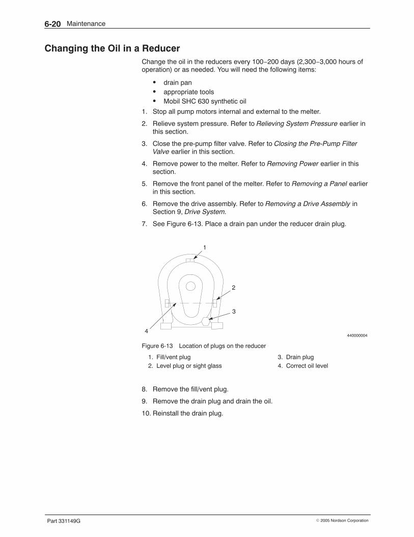
Maintenance6-20
Part 331149G � 2005 Nordson Corporation
Changing the Oil in a Reducer Change the oil in the reducers every 100−200 days (2,300−3,000 hours ofoperation) or as needed. You will need the following items:
� drain pan� appropriate tools� Mobil SHC 630 synthetic oil
1. Stop all pump motors internal and external to the melter.
2. Relieve system pressure. Refer to Relieving System Pressure earlier inthis section.
3. Close the pre-pump filter valve. Refer to Closing the Pre-Pump FilterValve earlier in this section.
4. Remove power to the melter. Refer to Removing Power earlier in thissection.
5. Remove the front panel of the melter. Refer to Removing a Panel earlierin this section.
6. Remove the drive assembly. Refer to Removing a Drive Assembly inSection 9, Drive System.
7. See Figure 6-13. Place a drain pan under the reducer drain plug.
440000004
3
2
4
1
Figure 6-13 Location of plugs on the reducer
1. Fill/vent plug2. Level plug or sight glass
3. Drain plug4. Correct oil level
8. Remove the fill/vent plug.
9. Remove the drain plug and drain the oil.
10. Reinstall the drain plug.
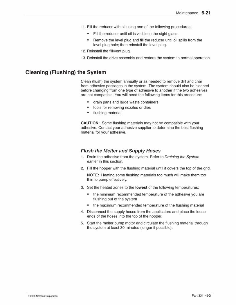
Maintenance 6-21
Part 331149G� 2005 Nordson Corporation
11. Fill the reducer with oil using one of the following procedures:
� Fill the reducer until oil is visible in the sight glass.
� Remove the level plug and fill the reducer until oil spills from thelevel plug hole; then reinstall the level plug.
12. Reinstall the fill/vent plug.
13. Reinstall the drive assembly and restore the system to normal operation.
Cleaning (Flushing) the System
Clean (flush) the system annually or as needed to remove dirt and charfrom adhesive passages in the system. The system should also be cleanedbefore changing from one type of adhesive to another if the two adhesivesare not compatible. You will need the following items for this procedure:
� drain pans and large waste containers� tools for removing nozzles or dies� flushing material
CAUTION: Some flushing materials may not be compatible with youradhesive. Contact your adhesive supplier to determine the best flushingmaterial for your adhesive.
Flush the Melter and Supply Hoses 1. Drain the adhesive from the system. Refer to Draining the System
earlier in this section.
2. Fill the hopper with the flushing material until it covers the top of the grid.
NOTE: Heating some flushing materials too much will make them toothin to pump effectively.
3. Set the heated zones to the lowest of the following temperatures:
� the minimum recommended temperature of the adhesive you areflushing out of the system
� the maximum recommended temperature of the flushing material
4. Disconnect the supply hoses from the applicators and place the looseends of the hoses into the top of the hopper.
5. Start the melter pump motor and circulate the flushing material throughthe system at least 30 minutes (longer if possible).
Maintenance6-22
Part 331149G � 2005 Nordson Corporation
Flush the Melter and Supply Hoses (contd)
6. Stop the melter pump motor and allow the system to cool:
Cool Down Time ActionEight hours or more Go to step 7.Less than eight hours Go to step 8.
7. After the system has cooled, open the hopper lid and remove the layerof adhesive and char that has collected on the surface of the flushingmaterial.
8. Remove and clean (or replace) the manifold filter screen. Refer toCleaning or Replacing a Manifold Filter Screen earlier in this section.
9. Remove the supply hoses from the hopper and reconnect them to theapplicators.
10. Go to the next procedure to flush the applicators and any return hoses.
Flush the Applicators and Any Return Hoses NOTE: For applicator-specific flushing procedures, refer to the applicatormanual.
1. Set the internal and external zone temperatures such that the applicatorzones and the adhesive are above the melting point of the adhesive.
2. Relieve system pressure. Refer to Relieving System Pressure earlier inthis section.
3. Place a drain pan under the dispensing modules on the applicators.
4. Remove the nozzles or dies from the applicators.
5. Start the melter and (if applicable) applicator pump motors to transferthe flushing material through the dispensing modules. Continue pumpinguntil the flushing material is clear and free of any contaminants.
NOTE: If you filter the flushing material as it drains, it can be reused.
6. Stop the melter and (if applicable) applicator pump motors.
7. If there are any return hoses, disconnect them from the melter manifoldand place the ends of the hoses into a container.
8. Start the melter and applicator pump motors to transfer the flushingmaterial through the return hoses. Continue pumping until the flushingmaterial is clear and free of any contaminants.
9. Stop the melter and applicator pump motors.
10. Reconnect the return hoses to the melter.
Maintenance 6-23
Part 331149G� 2005 Nordson Corporation
Restore the System to Normal Operation 1. Add adhesive to the hopper.
2. Heat the system to the recommended application temperature of theadhesive.
3. Disconnect the supply hoses from the applicators and pump theadhesive into a container until it is clean and free of contaminants.
4. Reconnect the supply hoses to the applicators and pump the adhesivethrough the dispensing modules until it is clean and free ofcontaminants.
5. Reinstall nozzles or dies on the applicators.
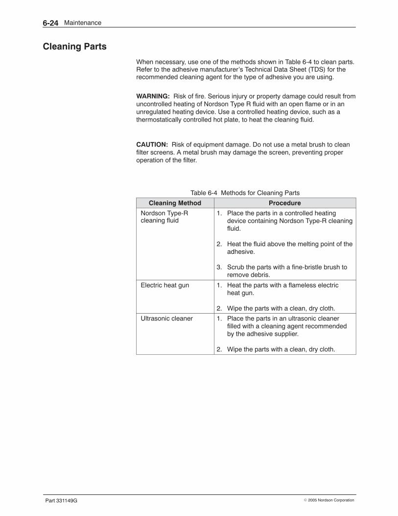
Maintenance6-24
Part 331149G � 2005 Nordson Corporation
Cleaning Parts
When necessary, use one of the methods shown in Table 6-4 to clean parts.Refer to the adhesive manufacturer’s Technical Data Sheet (TDS) for therecommended cleaning agent for the type of adhesive you are using.
WARNING: Risk of fire. Serious injury or property damage could result fromuncontrolled heating of Nordson Type R fluid with an open flame or in anunregulated heating device. Use a controlled heating device, such as athermostatically controlled hot plate, to heat the cleaning fluid.
CAUTION: Risk of equipment damage. Do not use a metal brush to cleanfilter screens. A metal brush may damage the screen, preventing properoperation of the filter.
Table 6-4 Methods for Cleaning Parts
Cleaning Method Procedure
Nordson Type-Rcleaning fluid
1. Place the parts in a controlled heatingdevice containing Nordson Type-R cleaningfluid.
2. Heat the fluid above the melting point of theadhesive.
3. Scrub the parts with a fine-bristle brush toremove debris.
Electric heat gun 1. Heat the parts with a flameless electricheat gun.
2. Wipe the parts with a clean, dry cloth.
Ultrasonic cleaner 1. Place the parts in an ultrasonic cleanerfilled with a cleaning agent recommendedby the adhesive supplier.
2. Wipe the parts with a clean, dry cloth.
Temperature Control System 7-1
Part 331149G� 2005 Nordson Corporation
Section 7Temperature Control System
WARNING: Allow only personnel with appropriate training and experienceto operate or service the equipment. The use of untrained or inexperiencedpersonnel to operate or service the equipment can result in injury, includingdeath, to themselves and others, and damage to the equipment.
Introduction The section contains troubleshooting and repair procedures for the melter’stemperature control system, which includes the controls and the heaters,resistance temperature detectors (RTDs), and thermoswitches on heatedcomponents. For electrical schematics and wiring diagrams, refer toElectrical Schematics and Wiring Diagrams in Section 13, Technical Data.
Troubleshooting of the temperature control system begins when the controlsystem provides an alarm or when a component (heated zone) does notheat properly. If you try all the troubleshooting suggestions in this sectionand still cannot solve the problem, contact your Nordson representative forassistance
Other troubleshooting information in this manual is located as follows:
� For hydraulic system problems, such as too much or too littleadhesive output, refer to Section 8, Hydraulic System.
� For drive system problems, such as a failed motor, refer toSection 9, Drive System.
� For system pressure problems, such as excessively high or lowsystem pressure, refer to Section 10, Pressure Monitoring.
� For level control problems, refer to Section 11, Level Control Option.
� For applicator or adhesive pattern problems, refer to the applicatormanual.
You will need a sufficient inventory of spare parts and supplies. Eachprocedure is preceded by a list of the parts and supplies you will need.Refer to Section 12, Parts, for the part numbers for all parts and supplies.
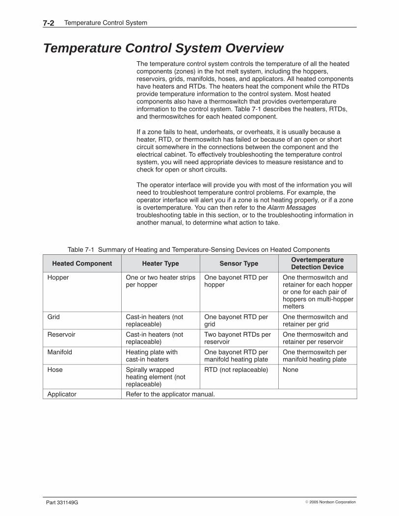
Temperature Control System7-2
Part 331149G � 2005 Nordson Corporation
Temperature Control System Overview The temperature control system controls the temperature of all the heatedcomponents (zones) in the hot melt system, including the hoppers,reservoirs, grids, manifolds, hoses, and applicators. All heated componentshave heaters and RTDs. The heaters heat the component while the RTDsprovide temperature information to the control system. Most heatedcomponents also have a thermoswitch that provides overtemperatureinformation to the control system. Table 7-1 describes the heaters, RTDs,and thermoswitches for each heated component.
If a zone fails to heat, underheats, or overheats, it is usually because aheater, RTD, or thermoswitch has failed or because of an open or shortcircuit somewhere in the connections between the component and theelectrical cabinet. To effectively troubleshooting the temperature controlsystem, you will need appropriate devices to measure resistance and tocheck for open or short circuits.
The operator interface will provide you with most of the information you willneed to troubleshoot temperature control problems. For example, theoperator interface will alert you if a zone is not heating properly, or if a zoneis overtemperature. You can then refer to the Alarm Messagestroubleshooting table in this section, or to the troubleshooting information inanother manual, to determine what action to take.
Table 7-1 Summary of Heating and Temperature-Sensing Devices on Heated Components
Heated Component Heater Type Sensor Type OvertemperatureDetection Device
Hopper One or two heater stripsper hopper
One bayonet RTD perhopper
One thermoswitch andretainer for each hopperor one for each pair ofhoppers on multi-hoppermelters
Grid Cast-in heaters (notreplaceable)
One bayonet RTD pergrid
One thermoswitch andretainer per grid
Reservoir Cast-in heaters (notreplaceable)
Two bayonet RTDs perreservoir
One thermoswitch andretainer per reservoir
Manifold Heating plate withcast-in heaters
One bayonet RTD permanifold heating plate
One thermoswitch permanifold heating plate
Hose Spirally wrappedheating element (notreplaceable)
RTD (not replaceable) None
Applicator Refer to the applicator manual.
Temperature Control System 7-3
Part 331149G� 2005 Nordson Corporation
Troubleshooting Tables These troubleshooting tables describe problems you may encounter andprovide corrective actions for handling those problems. Refer to theappropriate troubleshooting table for the type of problem you areexperiencing:
� Alarm Messages� Component Heating Problems
WARNING: Always wear heat-protective clothing, goggles (ANSI Z87.1 orequivalent), and safety gloves when working with hot melt equipment.
WARNING: Risk of equipment damage, personal injury, or death. Onlyqualifed personnel may perform electrical troubleshooting activities. Followelectrical safety procedures and observe all high-voltage indicators.
WARNING: Before performing any electrical troubleshooting activity,disconnect and lock out electrical power as appropriate. Refer to RemovingPower in Section 6, Maintenance.
Alarm Messages Anytime an alarm occurs during the operation of the melter, the controlsystem will display an alarm message on the alarm screen andautomatically take the appropriate action. Depending on how serious thealarm is, the system will respond in one of the three ways, as shown inTable 7-2. Table 7-3 provides troubleshooting advice for each type of alarmmessage.
NOTE: These alarm messages are typical for a standard PanelMate orPanelView operator interface. The operator interface for your control systemmay differ.
NOTE: For ACM alarm-message troubleshooting, refer to the ACM manual.
Temperature Control System7-4
Part 331149G � 2005 Nordson Corporation
Alarm Messages (contd)
Table 7-2 Types of Temperature Control Alarms and Resulting System Response
Warning Alarms System Response
� High Temperature Warning
� Low Temperature Warning
� Data Value Out of Range
Warning is displayed on the alarm screen. Noaction is required.
Fault Alarms System Response
� Low Temperature Fault Removes the run-permissive signal from thepumps, disabling the pumps. Continues to heat allenabled zones
Shutdown Alarms System Response
� High Temperature Fault
� Overtemperature Thermoswitch Fault
� Main Contactor Failure
� 1794-IR8 RTD Module #1 Fault
� 1794-IR8 RTD Module #2 Fault
� 1794-IR8 RTD Module #3 Fault
� 1794-IR8 RTD Module #4 Fault
� 1794-IR8 RTD Module #5 Fault
� 1794-IE8 Analog Input Module #1 Fault
� 1771-SDN DeviceNet Scanner Fault
� 1794-ADN DNet IO Module Fault
� CE-1 Extension Cable Fault
� RTD Open Circuit
� RTD Short Circuit
Removes the run-permissive signal from thepumps, disabling the pumps, and removes powerfrom all heated zones
Temperature Control System 7-5
Part 331149G� 2005 Nordson Corporation
Table 7-3 Troubleshooting Advice for Temperature Control Alarms
Alarm Message Explanation Recommended Action
[Name of Zone]High TemperatureFault
The temperature on this zone is highenough to activate the hightemperature fault. The differencebetween the actual temperature andthe setpoint temperature is equal toor greater than the high fault deltasetting.
If this fault occurs frequently, considerincreasing the high fault delta setting. If thisfault occurs after changing the setpoint orchanging a PID value, adjust the PID tuningto prevent temperature overshoot. If thisfault occurs for no apparent reason, and ifthe zone is an external zone, make sure atemperature runaway has not occurred.Check the solid-state relay for the zone.
[Name of Zone]Low TemperatureFault
The temperature on this zone is lowenough to activate the lowtemperature fault. The differencebetween the actual temperature andthe setpoint temperature is equal toor greater than the low fault deltasetting.
Check for the following problems:
� heater failure (refer to the nexttroubleshooting table, ComponentHeating Problems)
� blown fuse (refer to the electricalschematics)
� defective solid-state relay
Internal HeatThermostat isOpen
The overtemperature thermoswitchhas tripped, indicating that an internalzone (hopper, grid, reservoir, ormanifold) has overheated.
The alarm for the high temperature fault hasnot worked properly. Prior to thethermoswitch tripping, a high temperaturefault should occur, removing power from allzones. Check for an appropriate high faultdelta setting. If the setting is appropriate,check for a problem in the control system.
Main ContactorFailure
The control system is trying to turn onthe main contactor but the contactorremains disengaged.
The thermostat has tripped (refer toOvertemperature Thermoswitch Fault earlierin this table) or there is a continuity problemin the thermostat wiring. Check also for adefective main contactor.
1794-IR8 RTDModule #1 Failure
The temperature-sensing module forzones 1−8 has failed.
Replace the module.
1794-IR8 RTDModule #2 Failure
The temperature-sensing module forzones 9−16 has failed.
Replace the module.
1794-IR8 RTDModule #3 Failure
The temperature-sensing module forzones 17−24 has failed.
Replace the module.
1794-IR8 RTDModule #4 Failure
The temperature-sensing module forzones 25−32 has failed.
Replace the module.
1794-IR8 RTDModule #5 Failure
The temperature-sensing module forzones 33−40 (ACM zones) has failed.
Replace the module.
1794-IR8 RTDModule #6 Failure
The temperature-sensing module forzones 41−48 (ACM zones) has failed.
Replace the module.
Continued on next page
Temperature Control System7-6
Part 331149G � 2005 Nordson Corporation
Alarm Messages (contd)
Table 7-3 Troubleshooting Advice for Temperature Control Alarms (contd)
Alarm Message Explanation Recommended Action
1794-IE8 AnalogInput Module #1Fault
The analog input module for pressurehas failed.
Replace the module.
1771-SDNDeviceNetScanner Fault
The scanner has locked up or failed. Turn the system off and back on. If this doesnot clear the fault, replace the scanner.
1794-ADN DNetIO Module Fault
The remote I/O communicationshardware for the I/O rack has failed.
Check the communications hardware andreplace as needed.
CE1 ExtensionCable Fault
The cable has become disconnectedor is faulty.
Reconnect or replace the cable asappropriate.
[Name of Zone]RTD Open Circuit
The RTD circuit for this zone is open. Check for the following problems:
� The zone is enabled but no hose,applicator, or valve is connected.
� The RTD for the zone has failed open.Refer to the next troubleshooting table,Component Heating Problems, asneeded.
� A cable or cordset is disconnected orloose.
� Some other continuity problem exists inthe circuit.
� The RTD input module has failed.
[Name of Zone]RTD Short Circuit
A short has occurred in the RTDcircuit for this zone.
Check first for a shorted cable, then for ashort in the RTD itself. Refer to the nexttroubleshooting table, Component HeatingProblems, as needed.
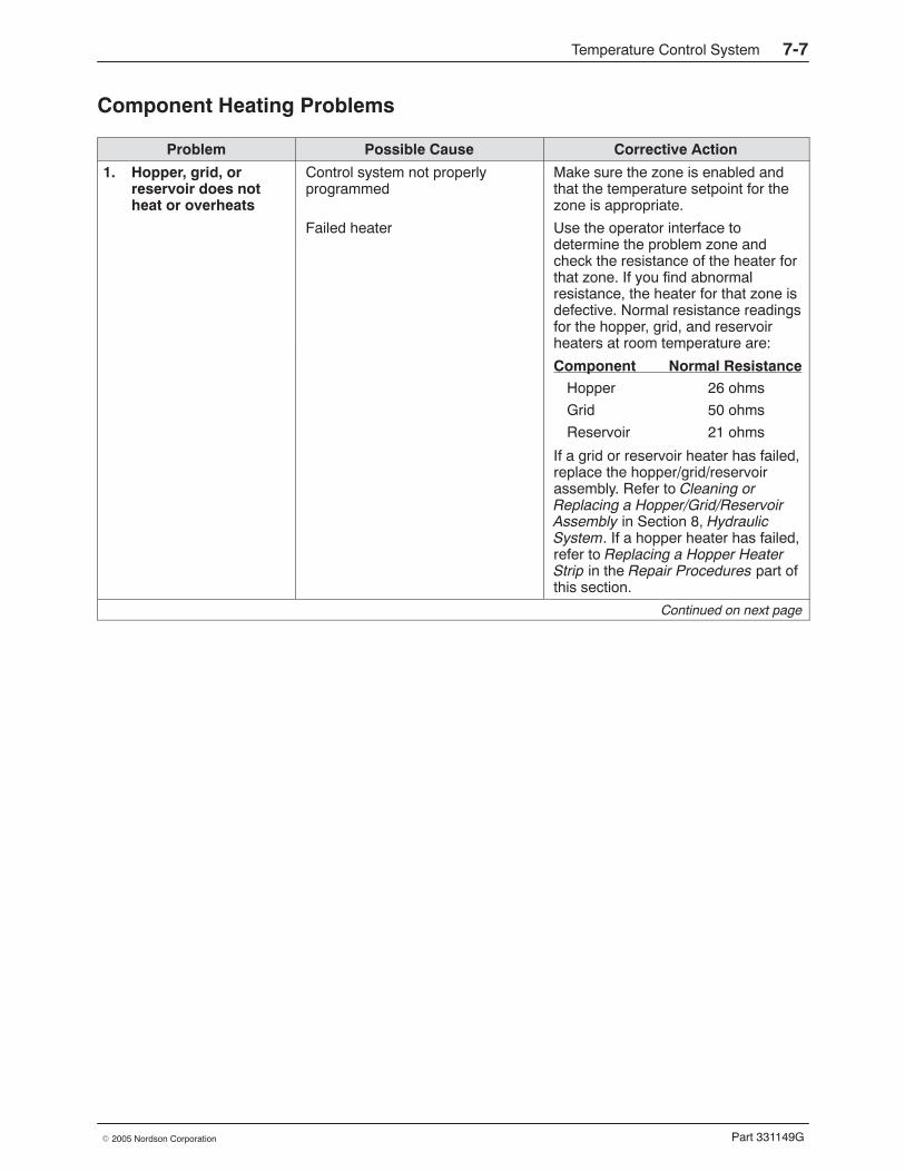
Temperature Control System 7-7
Part 331149G� 2005 Nordson Corporation
Component Heating Problems
Problem Possible Cause Corrective Action
1. Hopper, grid, orreservoir does notheat or overheats
Control system not properlyprogrammed
Make sure the zone is enabled andthat the temperature setpoint for thezone is appropriate.
Failed heater Use the operator interface todetermine the problem zone andcheck the resistance of the heater forthat zone. If you find abnormalresistance, the heater for that zone isdefective. Normal resistance readingsfor the hopper, grid, and reservoirheaters at room temperature are:
Component Normal ResistanceHopper 26 ohms
Grid 50 ohms
Reservoir 21 ohms
If a grid or reservoir heater has failed,replace the hopper/grid/reservoirassembly. Refer to Cleaning orReplacing a Hopper/Grid/ReservoirAssembly in Section 8, HydraulicSystem. If a hopper heater has failed,refer to Replacing a Hopper HeaterStrip in the Repair Procedures part ofthis section.
Continued on next page
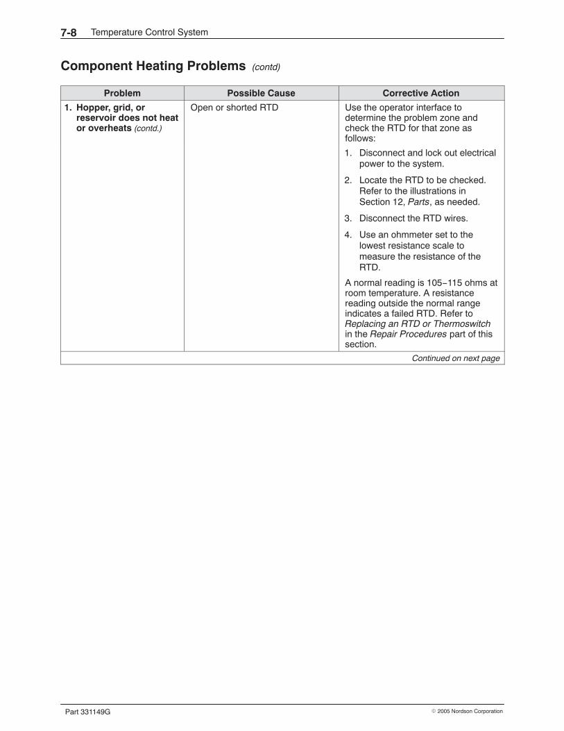
Temperature Control System7-8
Part 331149G � 2005 Nordson Corporation
Component Heating Problems (contd)
Problem Possible Cause Corrective Action
1. Hopper, grid, orreservoir does not heator overheats (contd.)
Open or shorted RTD Use the operator interface todetermine the problem zone andcheck the RTD for that zone asfollows:
1. Disconnect and lock out electricalpower to the system.
2. Locate the RTD to be checked.Refer to the illustrations inSection 12, Parts, as needed.
3. Disconnect the RTD wires.
4. Use an ohmmeter set to thelowest resistance scale tomeasure the resistance of theRTD.
A normal reading is 105−115 ohms atroom temperature. A resistancereading outside the normal rangeindicates a failed RTD. Refer toReplacing an RTD or Thermoswitchin the Repair Procedures part of thissection.
Continued on next page
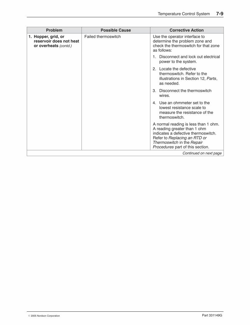
Temperature Control System 7-9
Part 331149G� 2005 Nordson Corporation
Problem Possible Cause Corrective Action
1. Hopper, grid, orreservoir does not heator overheats (contd.)
Failed thermoswitch Use the operator interface todetermine the problem zone andcheck the thermoswitch for that zoneas follows:
1. Disconnect and lock out electricalpower to the system.
2. Locate the defectivethermoswitch. Refer to theillustrations in Section 12, Parts,as needed.
3. Disconnect the thermoswitchwires.
4. Use an ohmmeter set to thelowest resistance scale tomeasure the resistance of thethermoswitch.
A normal reading is less than 1 ohm.A reading greater than 1 ohmindicates a defective thermoswitch.Refer to Replacing an RTD orThermoswitch in the RepairProcedures part of this section.
Continued on next page
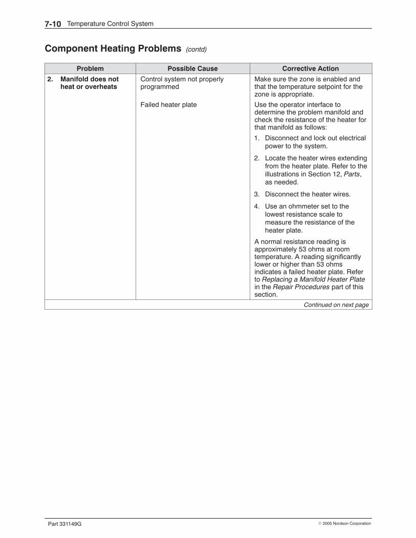
Temperature Control System7-10
Part 331149G � 2005 Nordson Corporation
Component Heating Problems (contd)
Problem Possible Cause Corrective Action
2. Manifold does notheat or overheats
Control system not properlyprogrammed
Make sure the zone is enabled andthat the temperature setpoint for thezone is appropriate.
Failed heater plate Use the operator interface todetermine the problem manifold andcheck the resistance of the heater forthat manifold as follows:
1. Disconnect and lock out electricalpower to the system.
2. Locate the heater wires extendingfrom the heater plate. Refer to theillustrations in Section 12, Parts,as needed.
3. Disconnect the heater wires.
4. Use an ohmmeter set to thelowest resistance scale tomeasure the resistance of theheater plate.
A normal resistance reading isapproximately 53 ohms at roomtemperature. A reading significantlylower or higher than 53 ohmsindicates a failed heater plate. Referto Replacing a Manifold Heater Platein the Repair Procedures part of thissection.
Continued on next page
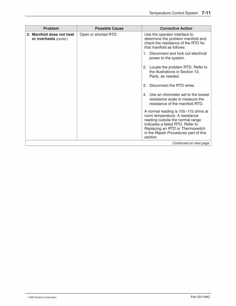
Temperature Control System 7-11
Part 331149G� 2005 Nordson Corporation
Problem Possible Cause Corrective Action
2. Manifold does not heator overheats (contd.)
Open or shorted RTD Use the operator interface todetermine the problem manifold andcheck the resistance of the RTD forthat manifold as follows:
1. Disconnect and lock out electricalpower to the system.
2. Locate the problem RTD. Refer tothe illustrations in Section 12,Parts, as needed.
3. Disconnect the RTD wires.
4. Use an ohmmeter set to the lowestresistance scale to measure theresistance of the manifold RTD.
A normal reading is 105−115 ohms atroom temperature. A resistancereading outside the normal rangeindicates a failed RTD. Refer toReplacing an RTD or Thermoswitchin the Repair Procedures part of thissection.
Continued on next page
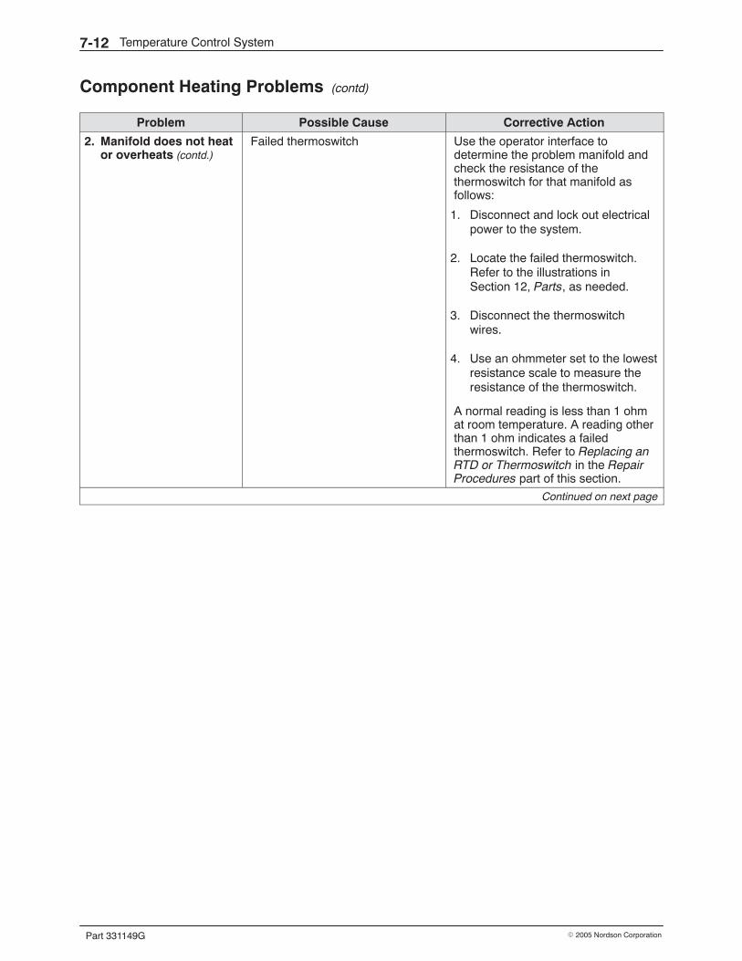
Temperature Control System7-12
Part 331149G � 2005 Nordson Corporation
Component Heating Problems (contd)
Problem Possible Cause Corrective Action
2. Manifold does not heator overheats (contd.)
Failed thermoswitch Use the operator interface todetermine the problem manifold andcheck the resistance of thethermoswitch for that manifold asfollows:
1. Disconnect and lock out electricalpower to the system.
2. Locate the failed thermoswitch.Refer to the illustrations inSection 12, Parts, as needed.
3. Disconnect the thermoswitchwires.
4. Use an ohmmeter set to the lowestresistance scale to measure theresistance of the thermoswitch.
A normal reading is less than 1 ohmat room temperature. A reading otherthan 1 ohm indicates a failedthermoswitch. Refer to Replacing anRTD or Thermoswitch in the RepairProcedures part of this section.
Continued on next page
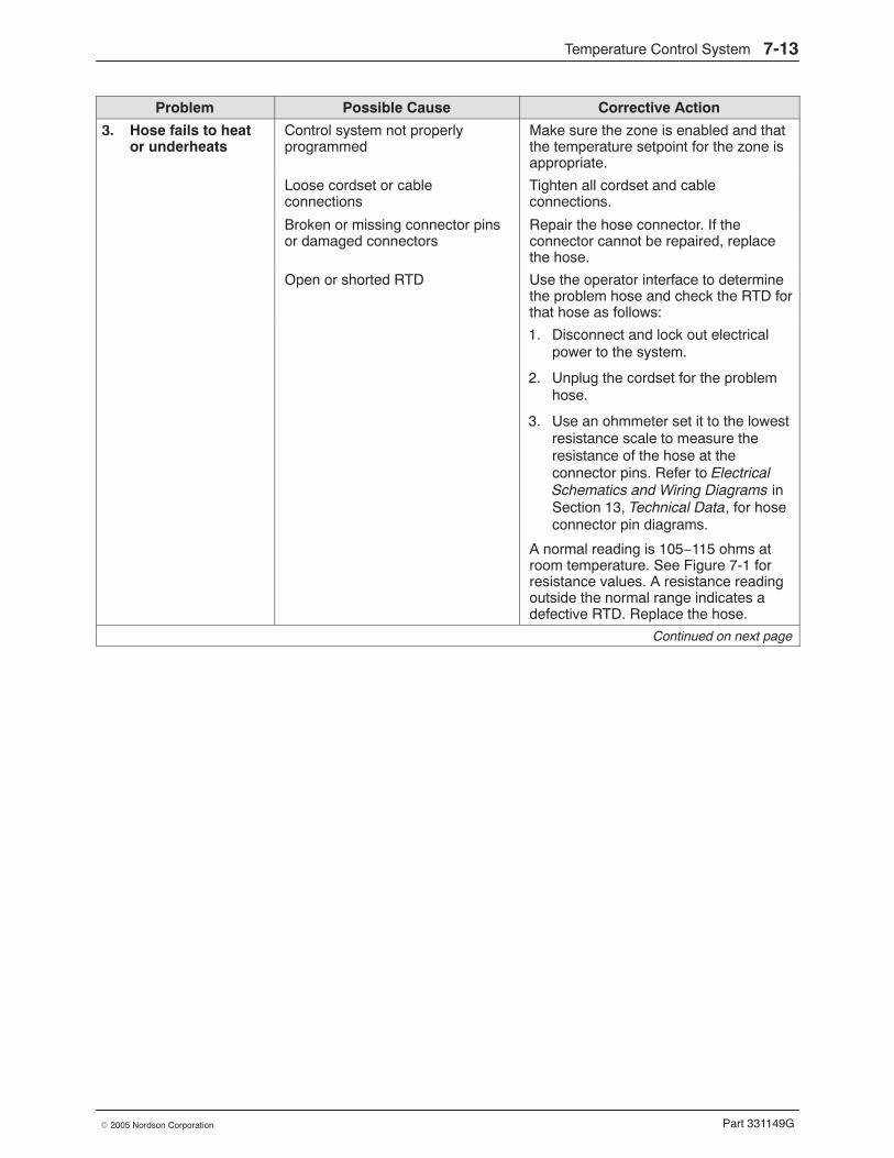
Temperature Control System 7-13
Part 331149G� 2005 Nordson Corporation
Problem Possible Cause Corrective Action
3. Hose fails to heator underheats
Control system not properlyprogrammed
Make sure the zone is enabled and thatthe temperature setpoint for the zone isappropriate.
Loose cordset or cableconnections
Tighten all cordset and cableconnections.
Broken or missing connector pinsor damaged connectors
Repair the hose connector. If theconnector cannot be repaired, replacethe hose.
Open or shorted RTD Use the operator interface to determinethe problem hose and check the RTD forthat hose as follows:
1. Disconnect and lock out electricalpower to the system.
2. Unplug the cordset for the problemhose.
3. Use an ohmmeter set it to the lowestresistance scale to measure theresistance of the hose at theconnector pins. Refer to ElectricalSchematics and Wiring Diagrams inSection 13, Technical Data, for hoseconnector pin diagrams.
A normal reading is 105−115 ohms atroom temperature. See Figure 7-1 forresistance values. A resistance readingoutside the normal range indicates adefective RTD. Replace the hose.
Continued on next page
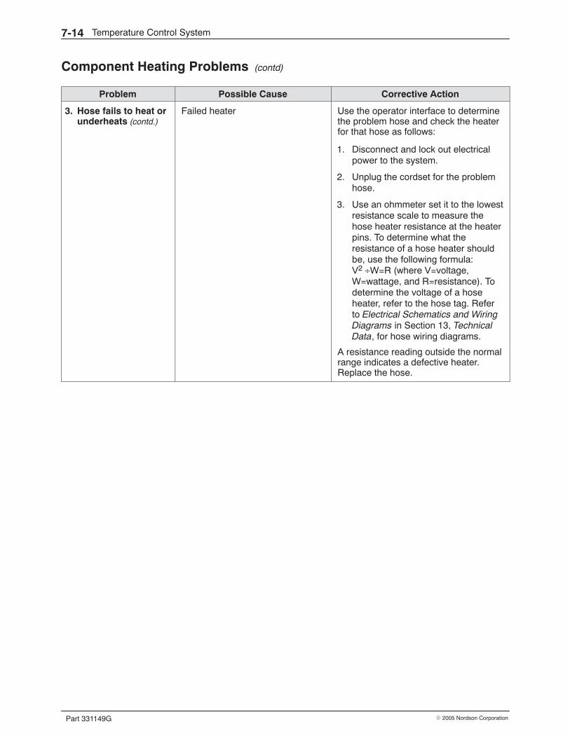
Temperature Control System7-14
Part 331149G � 2005 Nordson Corporation
Component Heating Problems (contd)
Problem Possible Cause Corrective Action
3. Hose fails to heat orunderheats (contd.)
Failed heater Use the operator interface to determinethe problem hose and check the heaterfor that hose as follows:
1. Disconnect and lock out electricalpower to the system.
2. Unplug the cordset for the problemhose.
3. Use an ohmmeter set it to the lowestresistance scale to measure thehose heater resistance at the heaterpins. To determine what theresistance of a hose heater shouldbe, use the following formula:V2 ÷W=R (where V=voltage,W=wattage, and R=resistance). Todetermine the voltage of a hoseheater, refer to the hose tag. Referto Electrical Schematics and WiringDiagrams in Section 13, TechnicalData, for hose wiring diagrams.
A resistance reading outside the normalrange indicates a defective heater.Replace the hose.
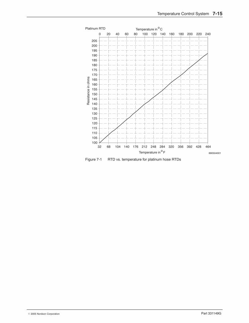
Temperature Control System 7-15
Part 331149G� 2005 Nordson Corporation
690504001
205
200
195
190
185
180
175
170
165
160
155
150
145
140
135
130
125
120
115
110
105
10032 68 104 140 176 212 248 284 320 356 392 428 464
Temperature in Fo
Res
ista
nce
in o
hms
0 20 40 60 80 100 120 140 160 180 200 220 240Temperature in CoPlatinum RTD
Figure 7-1 RTD vs. temperature for platinum hose RTDs
Temperature Control System7-16
Part 331149G � 2005 Nordson Corporation
Repair Procedures Troubleshooting may identify needed repairs. This part of Section 7 containsprocedures for
� replacing a hopper heater strip� replacing an RTD or thermoswitch� replacing a manifold heater plate
These procedures require some special knowledge. Procedures that can beeasily performed without special knowledge, such as replacing a cable, arenot included. Before performing any repair, be sure to
� review Section 1, Safety
� have the required parts and supplies on hand. They are listed at thebeginning of each procedure.
� refer to the illustrations in Section 12, Parts, as needed forreplacement part numbers and detailed parts lists and illustrations ofthe melter components
WARNING: Always wear heat-protective clothing, goggles (ANSI Z87.1 orequivalent), and safety gloves when working with hot melt equipment.
WARNING: Before performing any repair, relieve system pressure. Refer toRelieving System Pressure in Section 6, Maintenance.
WARNING: Risk of equipment damage, personal injury, or death. Onlyqualifed personnel may perform electrical repairs. Follow electrical safetyprocedures and observe all high-voltage indicators.
WARNING: Before performing any electrical repair, disconnect and lock outelectrical power as appropriate. Refer to Removing Power in Section 6,Maintenance.
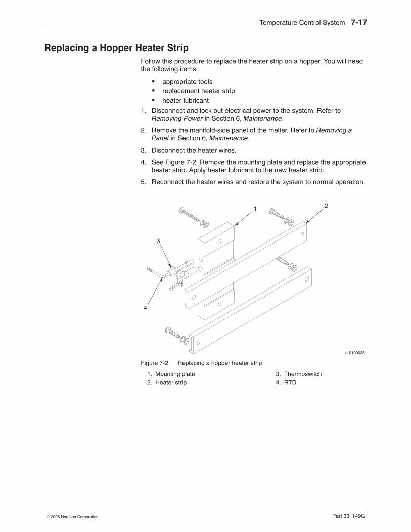
Temperature Control System 7-17
Part 331149G� 2005 Nordson Corporation
Replacing a Hopper Heater Strip Follow this procedure to replace the heater strip on a hopper. You will needthe following items:
� appropriate tools� replacement heater strip� heater lubricant
1. Disconnect and lock out electrical power to the system. Refer toRemoving Power in Section 6, Maintenance.
2. Remove the manifold-side panel of the melter. Refer to Removing aPanel in Section 6, Maintenance.
3. Disconnect the heater wires.
4. See Figure 7-2. Remove the mounting plate and replace the appropriateheater strip. Apply heater lubricant to the new heater strip.
5. Reconnect the heater wires and restore the system to normal operation.
410100038
1 2
3
4
Figure 7-2 Replacing a hopper heater strip
1. Mounting plate2. Heater strip
3. Thermoswitch4. RTD
Temperature Control System7-18
Part 331149G � 2005 Nordson Corporation
Replacing an RTD or Thermoswitch Follow this procedure to replace an RTD or a thermoswitch on the hopper,grid, reservoir, or manifold. You will need the following items:
� appropriate tools� replacement RTD or thermoswitch� heat sink compound (for thermoswitches)
1. Disconnect and lock out electrical power to the system. Refer toRemoving Power in Section 6, Maintenance.
2. Remove the appropriate panel of the melter. Refer to Removing a Panelin Section 6, Maintenance.
3. See Figure 7-3. Replace the failed component as shown in Table 7-4.
Table 7-4 Procedures for Replacing RTDs and Thermoswitches
Failed Component Replacement Procedure
RTD a. Disconnect the RTD wiring or cordset. Press inthe RTD bayonet ring, rotate the ring about onequarter-turn clockwise, and remove the RTD.
b. Insert the new RTD, press in the bayonet ring,and turn the ring about one quarter-turnclockwise.
c. Connect the new RTD wiring or cordset.
Thermoswitch a. Disconnect the thermoswitch wiring.
b. Loosen the thermoswitch retainer screw andremove the thermoswitch.
c. Apply a heat-sink compound to the newthermoswitch.
d. Insert the new thermoswitch and secure it withthe retainer.
e. Connect the new thermoswitch wiring.
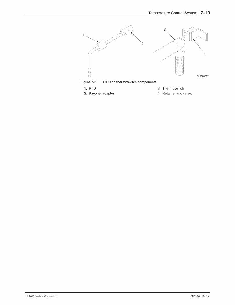
Temperature Control System 7-19
Part 331149G� 2005 Nordson Corporation
690500007
1
2
3
4
Figure 7-3 RTD and thermoswitch components
1. RTD2. Bayonet adapter
3. Thermoswitch4. Retainer and screw
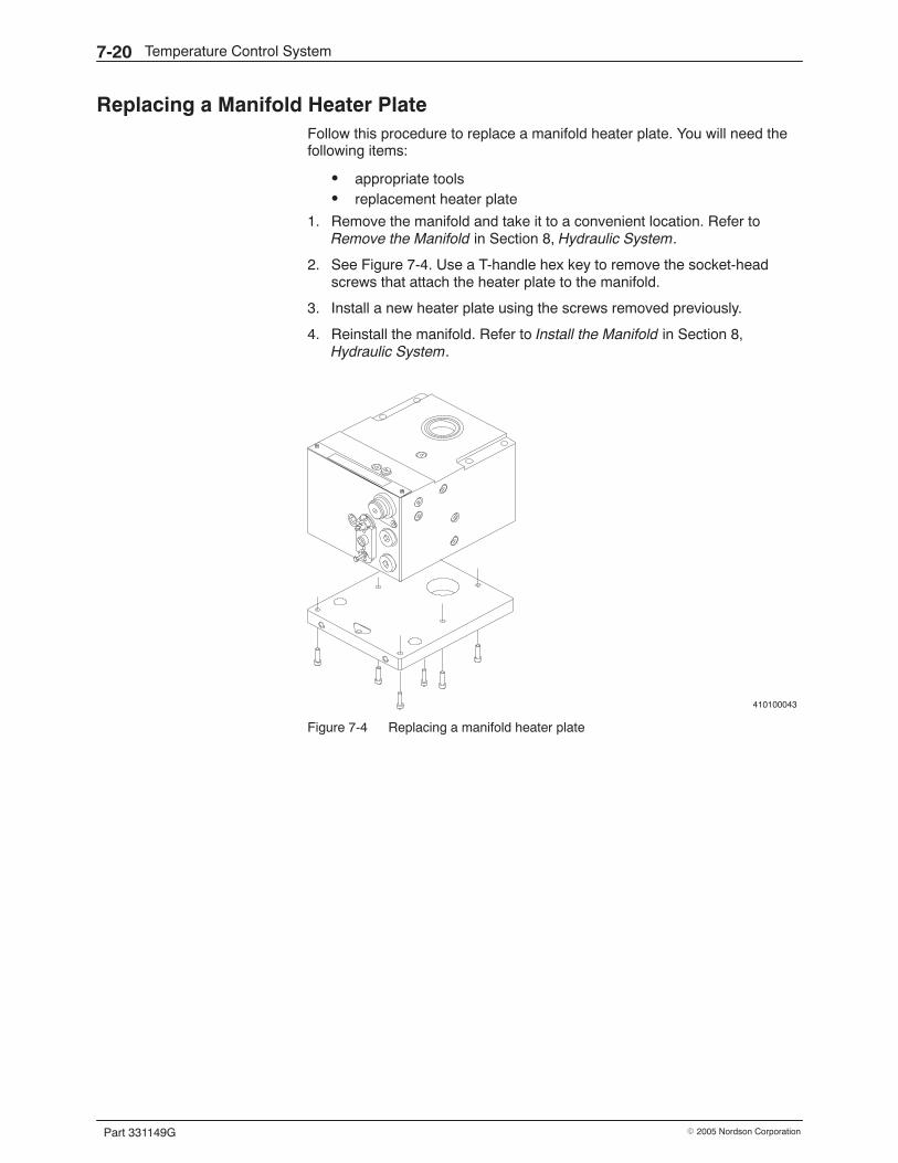
Temperature Control System7-20
Part 331149G � 2005 Nordson Corporation
Replacing a Manifold Heater Plate Follow this procedure to replace a manifold heater plate. You will need thefollowing items:
� appropriate tools� replacement heater plate
1. Remove the manifold and take it to a convenient location. Refer toRemove the Manifold in Section 8, Hydraulic System.
2. See Figure 7-4. Use a T-handle hex key to remove the socket-headscrews that attach the heater plate to the manifold.
3. Install a new heater plate using the screws removed previously.
4. Reinstall the manifold. Refer to Install the Manifold in Section 8,Hydraulic System.
410100043
Figure 7-4 Replacing a manifold heater plate
Hydraulic System 8-1
Part 331149G� 2005 Nordson Corporation
Section 8Hydraulic System
WARNING: Allow only personnel with appropriate training and experienceto operate or service the equipment. The use of untrained or inexperiencedpersonnel to operate or service the equipment can result in injury, includingdeath, to themselves and others, and damage to the equipment.
Introduction The section contains troubleshooting and repair procedures for the melter’shydraulic system, which includes the hopper, grid, reservoir, manifold, andpump assemblies and the hoses.
Troubleshooting of the hydraulic system begins when the flow of adhesiveto the the applicators diminishes or stops. If you try all the troubleshootingsuggestions in this section and still cannot solve the problem, contact yourNordson representative for assistance.
Other troubleshooting information in this manual is located as follows:
� For temperature control problems, such as a non-heating oroverheating component, refer to Section 7, Temperature ControlSystem.
� For drive system problems, such as a failed motor, refer toSection 9, Drive System.
� For system pressure problems, such as excessively high or lowsystem pressure, refer to Section 10, Pressure Monitoring.
� For level control problems, refer to Section 11, Level Control Option.
� For applicator or adhesive pattern problems, refer to the applicatormanual.
You will need a sufficient inventory of spare parts and supplies. Each repairprocedure is proceeded by a list of the parts and supplies you will need.Refer to Section 12, Parts, for the part numbers for all parts and supplies.
Hydraulic System8-2
Part 331149G � 2005 Nordson Corporation
Hydraulic System Overview The melter hydraulic system includes those components that transferadhesive through the hot melt system.
Major Components and Hydraulic Schematics Figure 8-1 shows the major components of a typical melter hydraulicsystem. The heated hopper provides storage capacity for the adhesive andraises the temperature of the adhesive to start the melting process. The gridcompletes the melting of the adhesive, which passes through the grid andinto the heated reservoir below. The reservoir keeps a supply of meltedadhesive ready for one or two pumps. The pre-pump filter valve preventsany large objects or debris from reaching the pump and also provides a wayto shut off flow to the pump during maintenance or repair. The pump, whichis located in the manifold, delivers the adhesive from the manifold to theapplicator by means of the heated hoses. Each manifold contains, inaddition to a pump, a pressure relief valve, a filter, and a control valve.Some of these components are described in more detail on the pagesfollowing the hydraulic flow diagrams.
Figures 8-2 through 8-5 show how adhesive flows through the system
� when the manifold is in the run mode, supplying adhesive to apressure-fed applicator that is dispensing the adhesive
� when the manifold is in the run mode, supplying adhesive to ametering applicator that is dispensing the adhesive
� when the manifold is in the recirculation mode, supplying adhesive toa metering applicator that is recirculating it back to the melterreservoir
� when the manifold is in the drain mode
NOTE: Melters with the level control option have a level control probeinstalled in the hopper lid(s). Refer to Section 11, Level Control Option, foran overview of the level control option.
Hydraulic System 8-3
Part 331149G� 2005 Nordson Corporation
1
2
3
4
5
6
Figure 8-1 Major components of a typical hydraulic system (single melter shown)
1. Hopper cover2. Gasket
3. Hopper/grid/reservoir assembly4. Pre-pump filter valve
5. Pump6. Manifold
Hydraulic System8-4
Part 331149G � 2005 Nordson Corporation
Run Mode, Pressure-Fed Applicator See Figure 8-2. Melted adhesive from the reservoir flows through thepre-pump filter valve to a metering pump in the manifold. From the pumpthe adhesive flows through a filter to a supply hose, which delivers theadhesive to the pressure-fed applicator. The applicator filters the adhesiveagain and then dispenses it onto the product.
When the dispensing module closes, pressure builds in the system until thepressure control valve in the manifold opens and sends the pump’s outputback to the reservoir.
Grid
Reservior
ÎÎÎÎÎÎÎÎ
ÎÎÎ
Pre-pump filter valve
Pressure control valve
Pressure-fedapplicator
Dispensingmodule
Pressurereliefvalve
Filter
Hose
Internalcirculationplug
Pump
Filter
Drain valve
Motor Reducer
Hopper
Figure 8-2 Hydraulic schematic of a melter with a pressure-fed applicator operating in the run mode
Hydraulic System 8-5
Part 331149G� 2005 Nordson Corporation
Run Mode, Metering Applicator See Figure 8-3. Melted adhesive from the reservoir flows through thepre-pump filter valve to a pump in the manifold. From the pump theadhesive flows through a filter to a supply hose, which deliversapproximately 80% of the adhesive to the metering applicator andrecirculates 20% through the pressure control valve back to the reservoir.The pump is set to provide this extra adhesive so that the metering pump inthe applicator always has a sufficient supply of adhesive.
In the metering applicator, the adhesive flows through a filter to the meteringpump, which typically produces either four or eight metered streams ofadhesive. Each adhesive stream is routed to a dispensing module thatdispenses the adhesive onto the product.
NOTE: The pressure control valve in the applicator is used to set thepressure in the system at about 13.8 bar (200 psi). The pressure controlvalve in the melter manifold is fully opened so that it has no effect on systempressure.
Grid
Reservior
ÎÎÎÎÎÎÎÎ
Pre-pump filter valve
Pressure control
Dispensing module
Return
Pressurereliefvalve
Externalcirculationplug
Pump
Filter
Drain valve
Motor Reducer
Hopper
ÎÎÎÎÎÎÎÎ
Filtervalve
Metering applicator
Pressure controlvalve
Pump
valve
Figure 8-3 Hydraulic schematic of a melter with a metering applicator operating in the run mode
Hydraulic System8-6
Part 331149G � 2005 Nordson Corporation
Recirculation Mode, Metering Applicator See Figure 8-4. When the dispensing modules on the metering applicatorclose, the return valves open, recirculating all of the adhesive back to thereservoir. When the dispensing modules open again, the return valves closeso that the all of the output streams from the metering pump are once againdispensed onto the product.
Grid
Reservior
ÎÎÎÎÎÎÎÎ
Pre-pump filter valve
Pressure control
Dispensing module
Return
Pressurereliefvalve
Externalcirculationplug
Pump
Filter
Drain valve
Motor Reducer
Hopper
ÎÎÎÎFilter
valve
Metering applicator
Pressure controlvalve
Pump
valve
Figure 8-4 Hydraulic schematic of a melter with a metering applicator operating in the recirculation mode
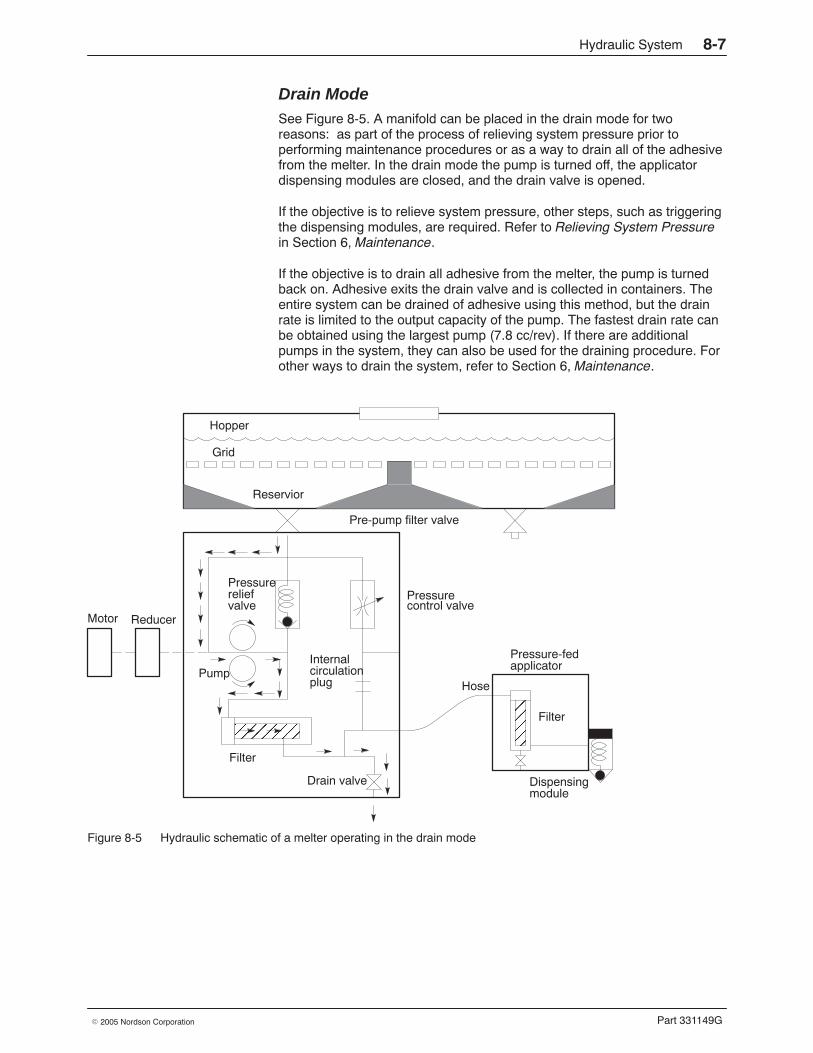
Hydraulic System 8-7
Part 331149G� 2005 Nordson Corporation
Drain Mode See Figure 8-5. A manifold can be placed in the drain mode for tworeasons: as part of the process of relieving system pressure prior toperforming maintenance procedures or as a way to drain all of the adhesivefrom the melter. In the drain mode the pump is turned off, the applicatordispensing modules are closed, and the drain valve is opened.
If the objective is to relieve system pressure, other steps, such as triggeringthe dispensing modules, are required. Refer to Relieving System Pressurein Section 6, Maintenance.
If the objective is to drain all adhesive from the melter, the pump is turnedback on. Adhesive exits the drain valve and is collected in containers. Theentire system can be drained of adhesive using this method, but the drainrate is limited to the output capacity of the pump. The fastest drain rate canbe obtained using the largest pump (7.8 cc/rev). If there are additionalpumps in the system, they can also be used for the draining procedure. Forother ways to drain the system, refer to Section 6, Maintenance.
Grid
Reservior
ÎÎÎÎÎÎÎÎ
ÎÎÎ
Pre-pump filter valve
Pressure control valve
Pressure-fedapplicator
Dispensingmodule
Pressurereliefvalve
Filter
Hose
Internalcirculationplug
Pump
Filter
Drain valve
Motor Reducer
Hopper
Figure 8-5 Hydraulic schematic of a melter operating in the drain mode
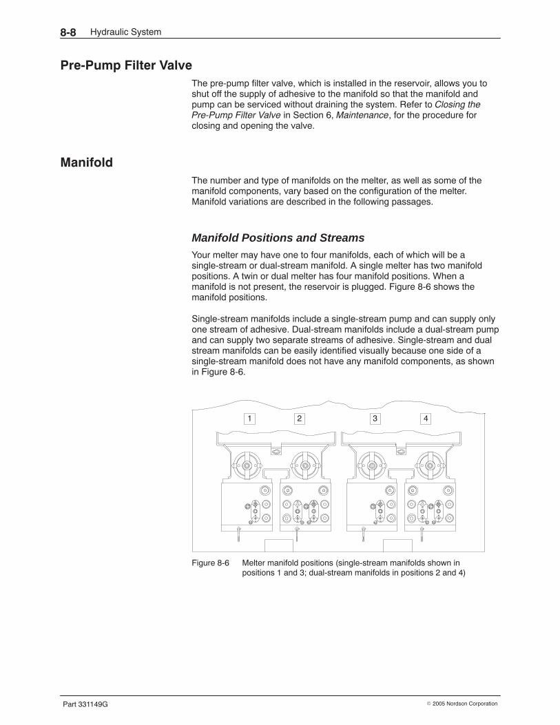
Hydraulic System8-8
Part 331149G � 2005 Nordson Corporation
Pre-Pump Filter Valve The pre-pump filter valve, which is installed in the reservoir, allows you toshut off the supply of adhesive to the manifold so that the manifold andpump can be serviced without draining the system. Refer to Closing thePre-Pump Filter Valve in Section 6, Maintenance, for the procedure forclosing and opening the valve.
Manifold The number and type of manifolds on the melter, as well as some of themanifold components, vary based on the configuration of the melter.Manifold variations are described in the following passages.
Manifold Positions and Streams Your melter may have one to four manifolds, each of which will be asingle-stream or dual-stream manifold. A single melter has two manifoldpositions. A twin or dual melter has four manifold positions. When amanifold is not present, the reservoir is plugged. Figure 8-6 shows themanifold positions.
Single-stream manifolds include a single-stream pump and can supply onlyone stream of adhesive. Dual-stream manifolds include a dual-stream pumpand can supply two separate streams of adhesive. Single-stream and dualstream manifolds can be easily identified visually because one side of asingle-stream manifold does not have any manifold components, as shownin Figure 8-6.
1 2 3 4
Figure 8-6 Melter manifold positions (single-stream manifolds shown inpositions 1 and 3; dual-stream manifolds in positions 2 and 4)
Hydraulic System 8-9
Part 331149G� 2005 Nordson Corporation
Manifold Components All manifolds include a filter, a drain valve, a pressure relief valve, one ofthree types of control valve, two or four pressure transducers, a pump, anda heating plate. Table 8-1 describes the function of each of thesecomponents.
Table 8-1 Function of the Manifold Components
Manifold Component Function
Filter Removes char and debris from the adhesivebefore it enters the pump
Drain valve Used for filter flushing and relieving systempressure; may also be used to drain adhesivefrom the manifold
Pressure relief valve Opens when the system reachesapproximately 90 bar (1,300 psi) to prevent anoverpressure condition
Control valve Helps the melter maintain constant pressure inthe system. There are three types of controlvalve: pressure control valve, flow controlvalve, and air-operated pressure control valve.To determine which type of control valve isinstalled on your melter, refer to Explanation ofthe Melter Configuration Code in Section 13,Technical Data. For information on how eachtype of valve works, refer to Control ValveAdjustment in Section 4, Setup.
Pump Transfers adhesive from the manifold to thehoses
Pressure transducer Provides pre- and/or post-filter systempressure data to the control system. Allmanifolds have one or two post-filter pressuretransducers. Some melters also have one ortwo pre-filter pressure transducers. Todetermine the number of transducers installedon your melter, refer to Explanation of theMelter Configuration Code in Section 13,Technical Data. For more information aboutpressure monitoring, refer to Section 10,Pressure Monitoring.
Heater plate Heats the manifold and provides temperaturesensing data to the control system. Refer toSection 7, Temperature Control System, formore information.
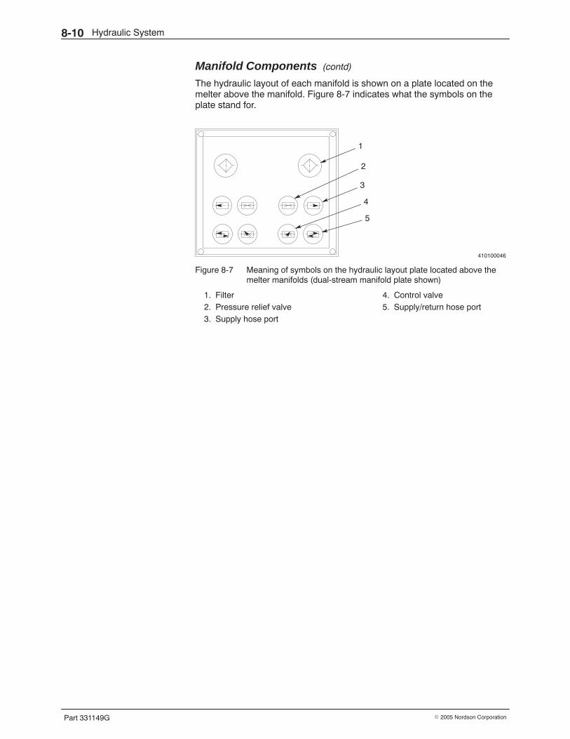
Hydraulic System8-10
Part 331149G � 2005 Nordson Corporation
Manifold Components (contd)
The hydraulic layout of each manifold is shown on a plate located on themelter above the manifold. Figure 8-7 indicates what the symbols on theplate stand for.
410100046
1
3
5
2
4
Figure 8-7 Meaning of symbols on the hydraulic layout plate located above themelter manifolds (dual-stream manifold plate shown)
1. Filter2. Pressure relief valve3. Supply hose port
4. Control valve5. Supply/return hose port
Hydraulic System 8-11
Part 331149G� 2005 Nordson Corporation
Manifold Circulation Manifolds may be internally or externally circulating. On internally circulatingmanifolds, only supply hoses are used. On externally circulating manifolds,both supply and return hoses are used so that adhesive is recirculated backto the melter. The type of circulation in the manifold is controlled by a pluginstalled in the bottom of the manifold. Internally circulating manifolds havean internal circulation plug while externally circulating manifolds have anexternal circulation plug. The type of circulation can be changed ifnecessary. Refer to Changing the Circulation in a Manifold in Section 3,Installation. Figure 8-8 shows the internal and external circulation plugs.
410100047
1
2
Figure 8-8 Manifold circulation plugs (dual-stream manifold shown)
1. External circulation plug 2. Internal circulation plug
Hoses Flexible, electrically heated hoses transport adhesive from one piece ofequipment to another. Hoses can be used in three ways:
� as supply hoses that carry adhesive from the melter to an applicatoror metering station in internally or externally circulating systems
� as cascade hoses that carry adhesive from one applicator to anotheror from one metering station to another in externally circulatingsystems with multiple applicators
� as return hoses that carry adhesive from an applicator or meteringstation back to the melter in externally circulating systems
NOTE: Hoses are not field-repairable. A defective hose must be replacedwith a new hose.
Hydraulic System8-12
Part 331149G � 2005 Nordson Corporation
Troubleshooting Tables The troubleshooting tables in this section describe the kinds of hydraulicsystem problems you may encounter and provide corrective actions forhandling those problems.
Refer to the appropriate troubleshooting table for the type of problem youare experiencing:
� Leakage Problems� Adhesive Output Problems
NOTE: For applicator problems or adhesive pattern problems, refer to thetroubleshooting information in the applicator manual.
WARNING: Always wear heat-protective clothing, goggles (ANSI Z87.1 orequivalent), and safety gloves when working with hot melt equipment.
WARNING: Before performing any troubleshooting activity on hydraulicsystem components, relieve system pressure. Refer to Relieving SystemPressure in Section 6, Maintenance.
WARNING: Before performing any troubleshooting activity on hydraulicsystem components, disconnect and lock out electrical power asappropriate. Refer to Removing Power in Section 6, Maintenance.
Leakage Problems
Problem Possible Cause Corrective Action
1. Leaks betweenstacked hoppers
Damaged hopper seal Replace the hopper seal. Refer toCleaning or Replacing aHopper/Grid/Reservoir Assembly inthe Repair Procedures part of thissection.
2. Leaks at pump bolt onmanifold
Loose pump bolt or worn pumpbolt O-rings
Tighten the pump bolt or replace thebolt and O-ring assembly. Refer toChecking the Torque on a Pump Boltin Section 6, Maintenance.
3. Leaks at a hoseconnection
Loose hydraulic connection Tighten the connection.
Failed hose fitting O-ring orstripped threads on hose fitting
Replace the hose fitting and/orO-ring.
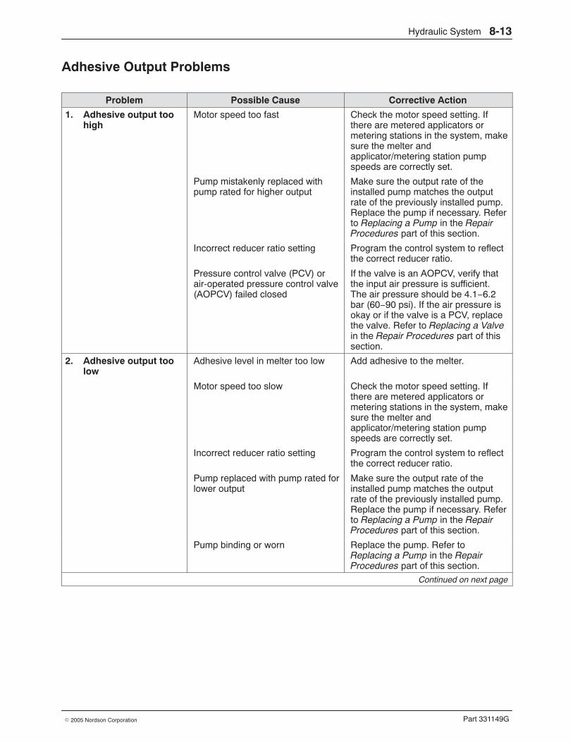
Hydraulic System 8-13
Part 331149G� 2005 Nordson Corporation
Adhesive Output Problems
Problem Possible Cause Corrective Action
1. Adhesive output toohigh
Motor speed too fast Check the motor speed setting. Ifthere are metered applicators ormetering stations in the system, makesure the melter andapplicator/metering station pumpspeeds are correctly set.
Pump mistakenly replaced withpump rated for higher output
Make sure the output rate of theinstalled pump matches the outputrate of the previously installed pump.Replace the pump if necessary. Referto Replacing a Pump in the RepairProcedures part of this section.
Incorrect reducer ratio setting Program the control system to reflectthe correct reducer ratio.
Pressure control valve (PCV) orair-operated pressure control valve(AOPCV) failed closed
If the valve is an AOPCV, verify thatthe input air pressure is sufficient.The air pressure should be 4.1−6.2bar (60−90 psi). If the air pressure isokay or if the valve is a PCV, replacethe valve. Refer to Replacing a Valvein the Repair Procedures part of thissection.
2. Adhesive output toolow
Adhesive level in melter too low Add adhesive to the melter.
Motor speed too slow Check the motor speed setting. Ifthere are metered applicators ormetering stations in the system, makesure the melter andapplicator/metering station pumpspeeds are correctly set.
Incorrect reducer ratio setting Program the control system to reflectthe correct reducer ratio.
Pump replaced with pump rated forlower output
Make sure the output rate of theinstalled pump matches the outputrate of the previously installed pump.Replace the pump if necessary. Referto Replacing a Pump in the RepairProcedures part of this section.
Pump binding or worn Replace the pump. Refer toReplacing a Pump in the RepairProcedures part of this section.
Continued on next page
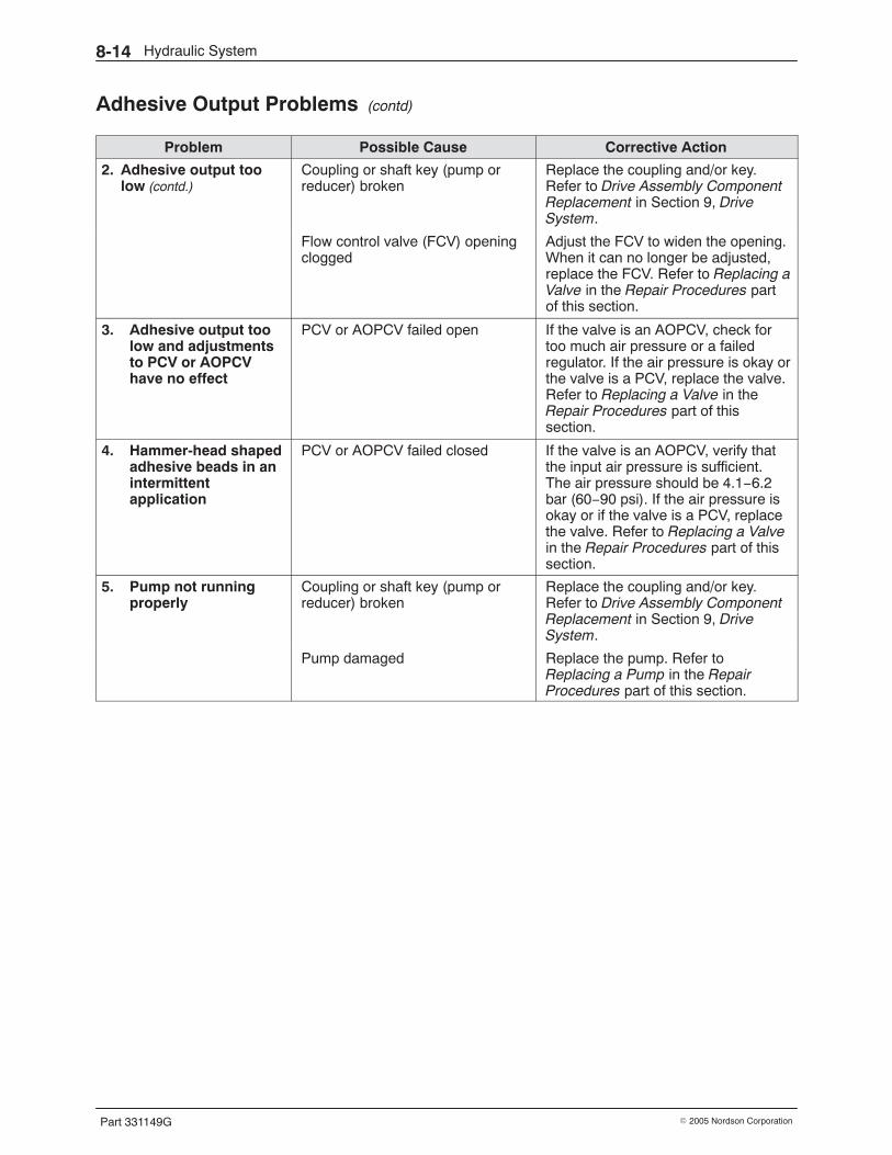
Hydraulic System8-14
Part 331149G � 2005 Nordson Corporation
Adhesive Output Problems (contd)
Problem Possible Cause Corrective Action
2. Adhesive output toolow (contd.)
Coupling or shaft key (pump orreducer) broken
Replace the coupling and/or key.Refer to Drive Assembly ComponentReplacement in Section 9, DriveSystem.
Flow control valve (FCV) openingclogged
Adjust the FCV to widen the opening.When it can no longer be adjusted,replace the FCV. Refer to Replacing aValve in the Repair Procedures partof this section.
3. Adhesive output toolow and adjustmentsto PCV or AOPCVhave no effect
PCV or AOPCV failed open If the valve is an AOPCV, check fortoo much air pressure or a failedregulator. If the air pressure is okay orthe valve is a PCV, replace the valve.Refer to Replacing a Valve in theRepair Procedures part of thissection.
4. Hammer-head shapedadhesive beads in anintermittentapplication
PCV or AOPCV failed closed If the valve is an AOPCV, verify thatthe input air pressure is sufficient.The air pressure should be 4.1−6.2bar (60−90 psi). If the air pressure isokay or if the valve is a PCV, replacethe valve. Refer to Replacing a Valvein the Repair Procedures part of thissection.
5. Pump not runningproperly
Coupling or shaft key (pump orreducer) broken
Replace the coupling and/or key.Refer to Drive Assembly ComponentReplacement in Section 9, DriveSystem.
Pump damaged Replace the pump. Refer toReplacing a Pump in the RepairProcedures part of this section.
Hydraulic System 8-15
Part 331149G� 2005 Nordson Corporation
Repair Procedures Troubleshooting activities may identify needed repairs. This part ofSection 12 contains procedures for
� replacing a pump� replacing a valve� cleaning a hopper� replacing a hopper/grid/reservoir assembly� removing and installing a manifold
These procedures require some special knowledge. Procedures that can beeasily performed without special knowledge, such as replacing a hose, arenot included. Before performing any repair, be sure to
� review Section 1, Safety
� have the required parts and supplies on hand. They are listed at thebeginning of each procedure.
� refer to the illustrations in Section 12, Parts, as needed forreplacement part numbers and detailed parts lists and illustrations ofthe melter components
WARNING: Always wear heat-protective clothing, goggles (ANSI Z87.1 orequivalent), and safety gloves when working with hot melt equipment.
WARNING: Before performing any repair, relieve system pressure. Refer toRelieving System Pressure in Section 6, Maintenance.
WARNING: Before performing any repair, disconnect and lock out electricalpower as appropriate. Refer to Removing Power in Section 6, Maintenance.
NOTE: For maintenance procedures, such as flushing a manifold filter orcleaning the filter screen, refer to Section 6, Maintenance.
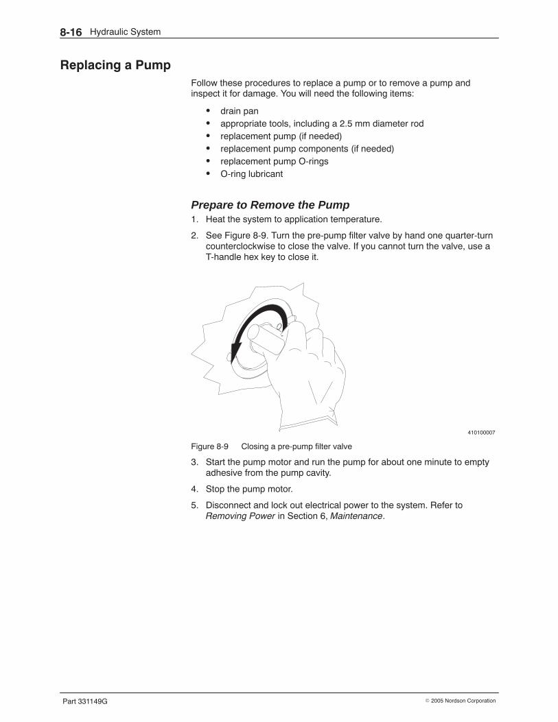
Hydraulic System8-16
Part 331149G � 2005 Nordson Corporation
Replacing a Pump Follow these procedures to replace a pump or to remove a pump andinspect it for damage. You will need the following items:
� drain pan� appropriate tools, including a 2.5 mm diameter rod� replacement pump (if needed)� replacement pump components (if needed)� replacement pump O-rings� O-ring lubricant
Prepare to Remove the Pump 1. Heat the system to application temperature.
2. See Figure 8-9. Turn the pre-pump filter valve by hand one quarter-turncounterclockwise to close the valve. If you cannot turn the valve, use aT-handle hex key to close it.
410100007
Figure 8-9 Closing a pre-pump filter valve
3. Start the pump motor and run the pump for about one minute to emptyadhesive from the pump cavity.
4. Stop the pump motor.
5. Disconnect and lock out electrical power to the system. Refer toRemoving Power in Section 6, Maintenance.
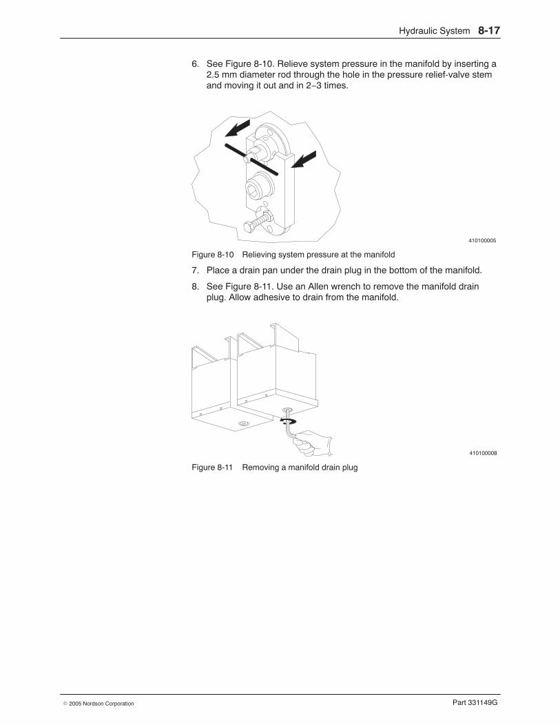
Hydraulic System 8-17
Part 331149G� 2005 Nordson Corporation
6. See Figure 8-10. Relieve system pressure in the manifold by inserting a2.5 mm diameter rod through the hole in the pressure relief-valve stemand moving it out and in 2−3 times.
410100005
Figure 8-10 Relieving system pressure at the manifold
7. Place a drain pan under the drain plug in the bottom of the manifold.
8. See Figure 8-11. Use an Allen wrench to remove the manifold drainplug. Allow adhesive to drain from the manifold.
410100008
Figure 8-11 Removing a manifold drain plug
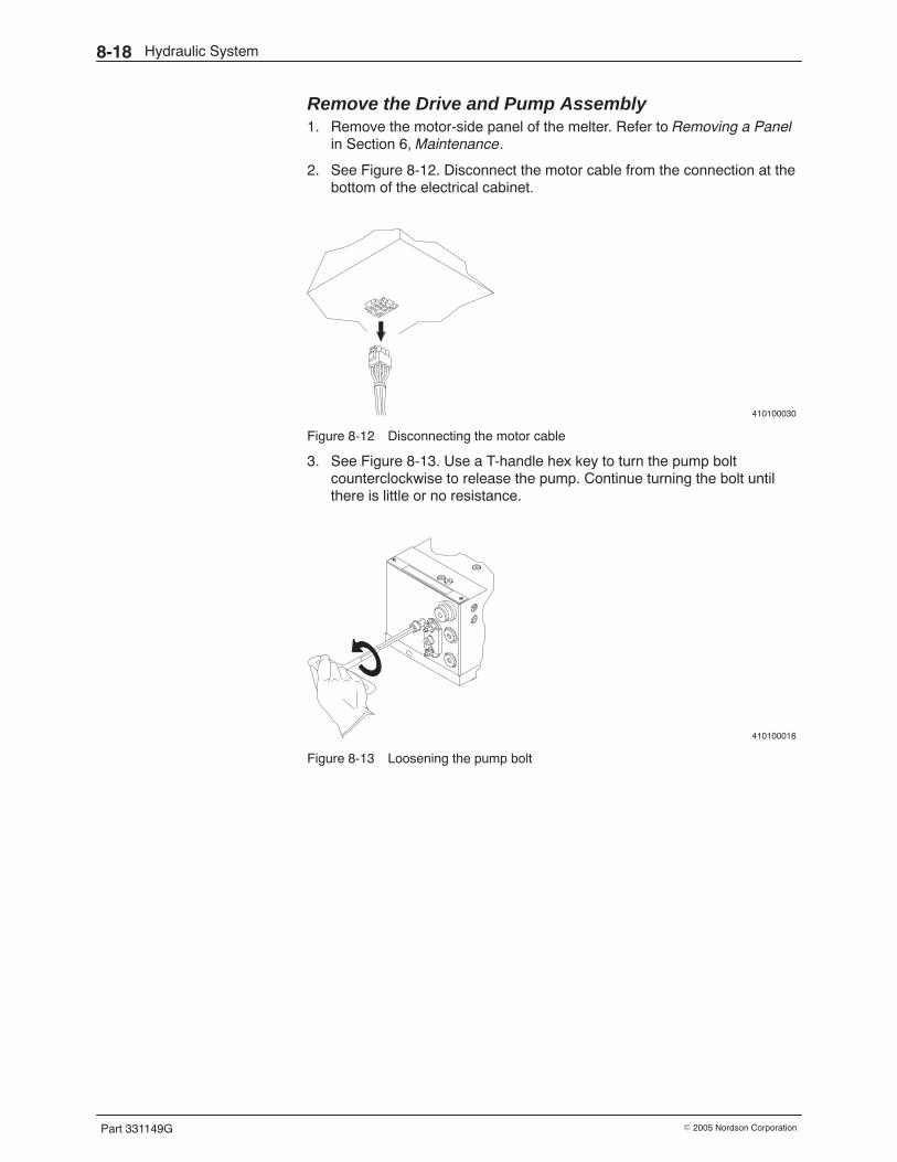
Hydraulic System8-18
Part 331149G � 2005 Nordson Corporation
Remove the Drive and Pump Assembly 1. Remove the motor-side panel of the melter. Refer to Removing a Panel
in Section 6, Maintenance.
2. See Figure 8-12. Disconnect the motor cable from the connection at thebottom of the electrical cabinet.
410100030
Figure 8-12 Disconnecting the motor cable
3. See Figure 8-13. Use a T-handle hex key to turn the pump boltcounterclockwise to release the pump. Continue turning the bolt untilthere is little or no resistance.
410100016
Figure 8-13 Loosening the pump bolt
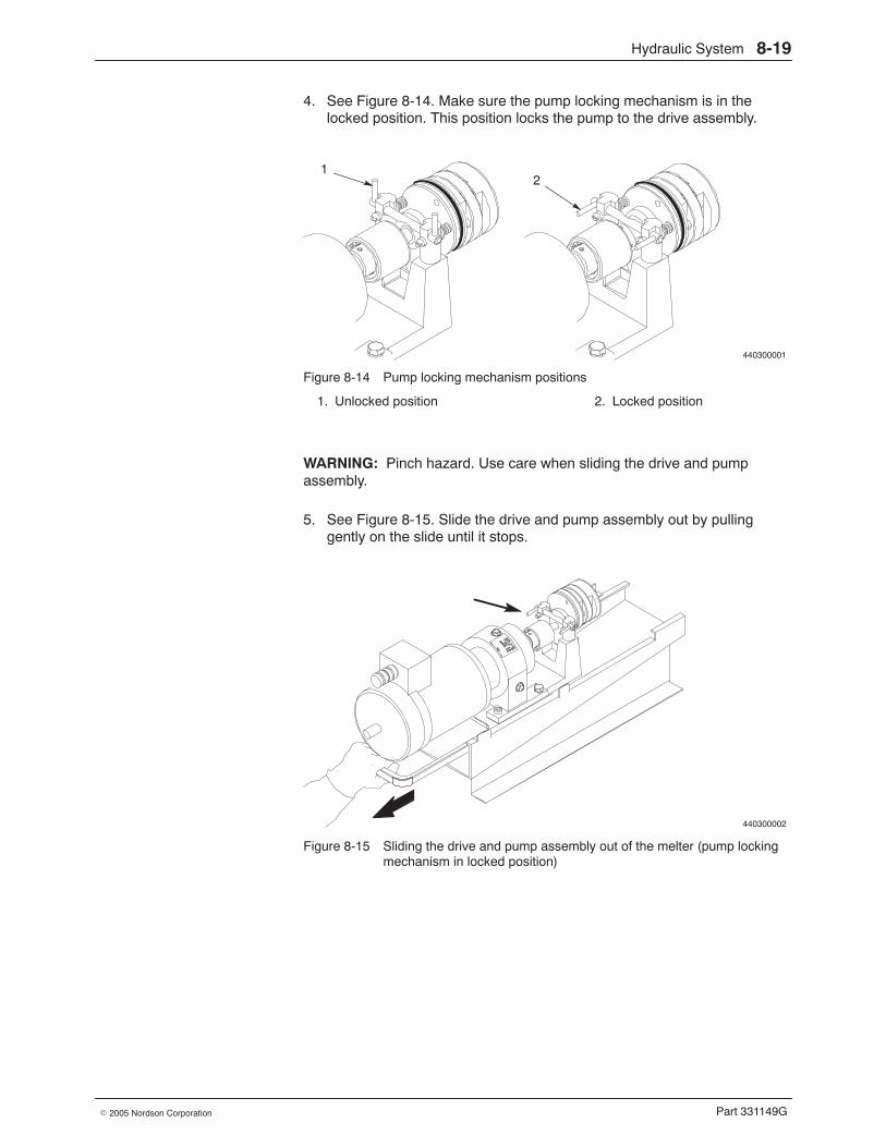
Hydraulic System 8-19
Part 331149G� 2005 Nordson Corporation
4. See Figure 8-14. Make sure the pump locking mechanism is in thelocked position. This position locks the pump to the drive assembly.
440300001
12
Figure 8-14 Pump locking mechanism positions
1. Unlocked position 2. Locked position
WARNING: Pinch hazard. Use care when sliding the drive and pumpassembly.
5. See Figure 8-15. Slide the drive and pump assembly out by pullinggently on the slide until it stops.
440300002
Figure 8-15 Sliding the drive and pump assembly out of the melter (pump lockingmechanism in locked position)
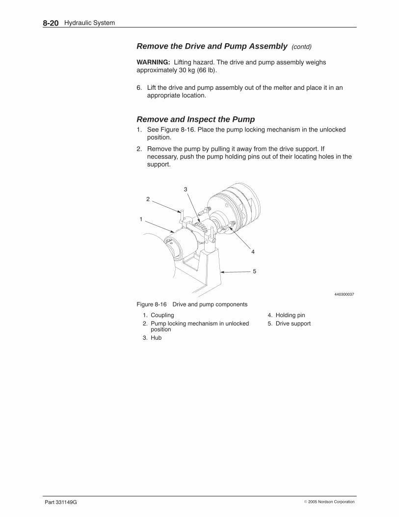
Hydraulic System8-20
Part 331149G � 2005 Nordson Corporation
Remove the Drive and Pump Assembly (contd)
WARNING: Lifting hazard. The drive and pump assembly weighsapproximately 30 kg (66 lb).
6. Lift the drive and pump assembly out of the melter and place it in anappropriate location.
Remove and Inspect the Pump 1. See Figure 8-16. Place the pump locking mechanism in the unlocked
position.
2. Remove the pump by pulling it away from the drive support. Ifnecessary, push the pump holding pins out of their locating holes in thesupport.
440300037
2
1
3
4
5
Figure 8-16 Drive and pump components
1. Coupling2. Pump locking mechanism in unlocked
position3. Hub
4. Holding pin5. Drive support
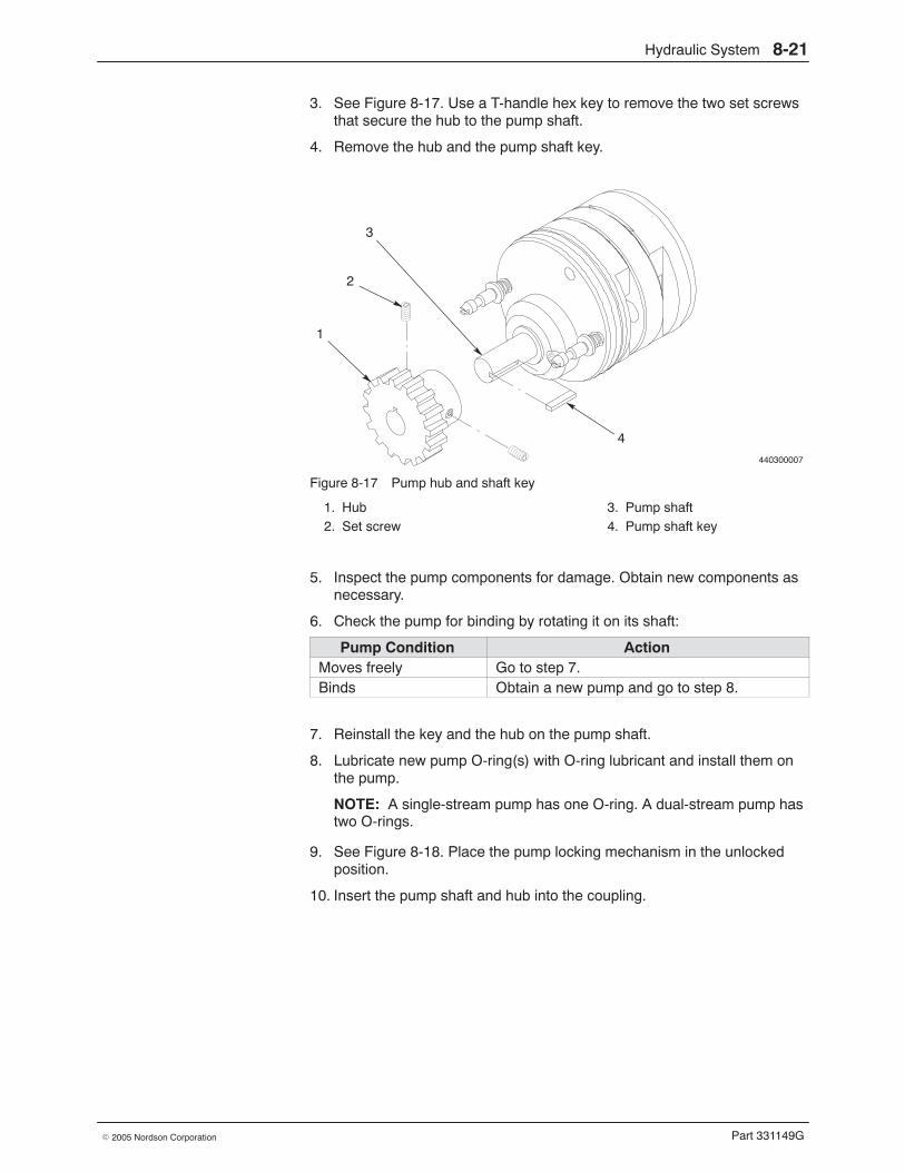
Hydraulic System 8-21
Part 331149G� 2005 Nordson Corporation
3. See Figure 8-17. Use a T-handle hex key to remove the two set screwsthat secure the hub to the pump shaft.
4. Remove the hub and the pump shaft key.
440300007
3
2
1
4
Figure 8-17 Pump hub and shaft key
1. Hub2. Set screw
3. Pump shaft4. Pump shaft key
5. Inspect the pump components for damage. Obtain new components asnecessary.
6. Check the pump for binding by rotating it on its shaft:
Pump Condition ActionMoves freely Go to step 7.Binds Obtain a new pump and go to step 8.
7. Reinstall the key and the hub on the pump shaft.
8. Lubricate new pump O-ring(s) with O-ring lubricant and install them onthe pump.
NOTE: A single-stream pump has one O-ring. A dual-stream pump hastwo O-rings.
9. See Figure 8-18. Place the pump locking mechanism in the unlockedposition.
10. Insert the pump shaft and hub into the coupling.
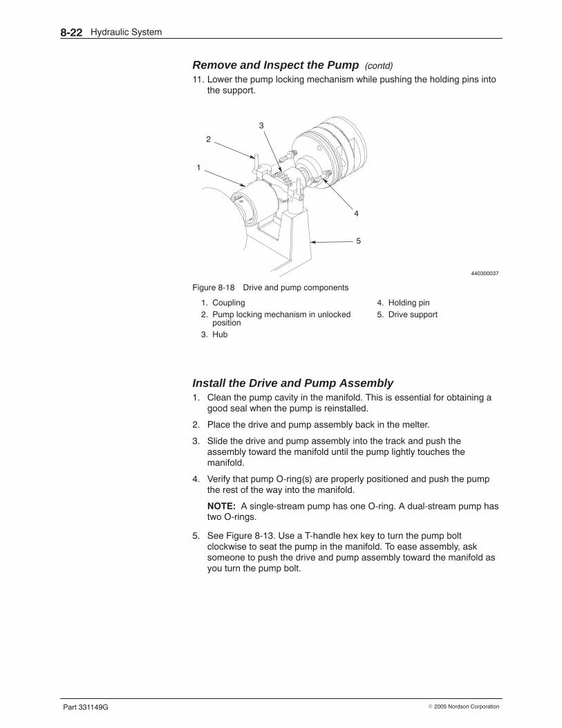
Hydraulic System8-22
Part 331149G � 2005 Nordson Corporation
Remove and Inspect the Pump (contd)
11. Lower the pump locking mechanism while pushing the holding pins intothe support.
440300037
2
1
3
4
5
Figure 8-18 Drive and pump components
1. Coupling2. Pump locking mechanism in unlocked
position3. Hub
4. Holding pin5. Drive support
Install the Drive and Pump Assembly 1. Clean the pump cavity in the manifold. This is essential for obtaining a
good seal when the pump is reinstalled.
2. Place the drive and pump assembly back in the melter.
3. Slide the drive and pump assembly into the track and push theassembly toward the manifold until the pump lightly touches themanifold.
4. Verify that pump O-ring(s) are properly positioned and push the pumpthe rest of the way into the manifold.
NOTE: A single-stream pump has one O-ring. A dual-stream pump hastwo O-rings.
5. See Figure 8-13. Use a T-handle hex key to turn the pump boltclockwise to seat the pump in the manifold. To ease assembly, asksomeone to push the drive and pump assembly toward the manifold asyou turn the pump bolt.
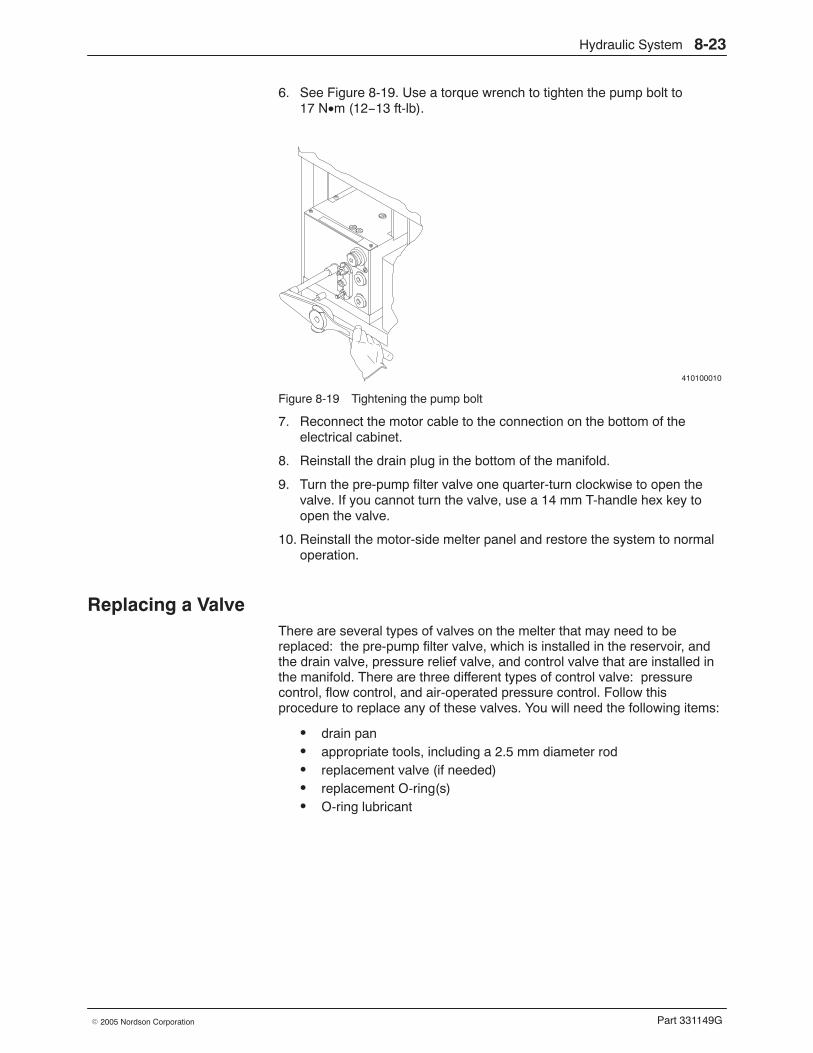
Hydraulic System 8-23
Part 331149G� 2005 Nordson Corporation
6. See Figure 8-19. Use a torque wrench to tighten the pump bolt to17 N•m (12−13 ft-lb).
410100010
Figure 8-19 Tightening the pump bolt
7. Reconnect the motor cable to the connection on the bottom of theelectrical cabinet.
8. Reinstall the drain plug in the bottom of the manifold.
9. Turn the pre-pump filter valve one quarter-turn clockwise to open thevalve. If you cannot turn the valve, use a 14 mm T-handle hex key toopen the valve.
10. Reinstall the motor-side melter panel and restore the system to normaloperation.
Replacing a Valve There are several types of valves on the melter that may need to bereplaced: the pre-pump filter valve, which is installed in the reservoir, andthe drain valve, pressure relief valve, and control valve that are installed inthe manifold. There are three different types of control valve: pressurecontrol, flow control, and air-operated pressure control. Follow thisprocedure to replace any of these valves. You will need the following items:
� drain pan� appropriate tools, including a 2.5 mm diameter rod� replacement valve (if needed)� replacement O-ring(s)� O-ring lubricant
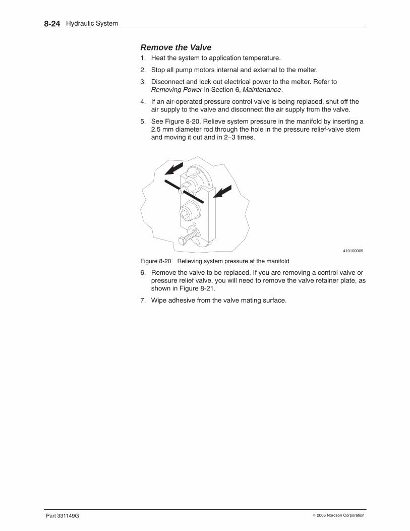
Hydraulic System8-24
Part 331149G � 2005 Nordson Corporation
Remove the Valve 1. Heat the system to application temperature.
2. Stop all pump motors internal and external to the melter.
3. Disconnect and lock out electrical power to the melter. Refer toRemoving Power in Section 6, Maintenance.
4. If an air-operated pressure control valve is being replaced, shut off theair supply to the valve and disconnect the air supply from the valve.
5. See Figure 8-20. Relieve system pressure in the manifold by inserting a2.5 mm diameter rod through the hole in the pressure relief-valve stemand moving it out and in 2−3 times.
410100005
Figure 8-20 Relieving system pressure at the manifold
6. Remove the valve to be replaced. If you are removing a control valve orpressure relief valve, you will need to remove the valve retainer plate, asshown in Figure 8-21.
7. Wipe adhesive from the valve mating surface.
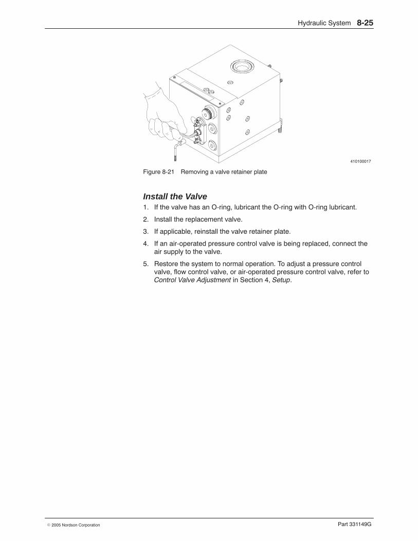
Hydraulic System 8-25
Part 331149G� 2005 Nordson Corporation
410100017
Figure 8-21 Removing a valve retainer plate
Install the Valve 1. If the valve has an O-ring, lubricant the O-ring with O-ring lubricant.
2. Install the replacement valve.
3. If applicable, reinstall the valve retainer plate.
4. If an air-operated pressure control valve is being replaced, connect theair supply to the valve.
5. Restore the system to normal operation. To adjust a pressure controlvalve, flow control valve, or air-operated pressure control valve, refer toControl Valve Adjustment in Section 4, Setup.
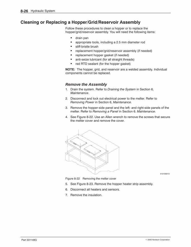
Hydraulic System8-26
Part 331149G � 2005 Nordson Corporation
Cleaning or Replacing a Hopper/Grid/Reservoir Assembly Follow these procedures to clean a hopper or to replace thehopper/grid/reservoir assembly. You will need the following items:
� drain pan� appropriate tools, including a 2.5 mm diameter rod� stiff-bristle brush� replacement hopper/grid/reservoir assembly (if needed)� replacement hopper gasket (if needed)� anti-seize lubricant (for all straight threads)� red RTD sealant (for the hopper gasket)
NOTE: The hopper, grid, and reservoir are a welded assembly. Individualcomponents cannot be replaced.
Remove the Assembly 1. Drain the system. Refer to Draining the System in Section 6,
Maintenance.
2. Disconnect and lock out electrical power to the melter. Refer toRemoving Power in Section 6, Maintenance.
3. Remove the hopper-side panel and the left- and right-side panels of themelter. Refer to Removing a Panel in Section 6. Maintenance.
4. See Figure 8-22. Use an Allen wrench to remove the screws that securethe melter cover and remove the cover.
410100013
Figure 8-22 Removing the melter cover
5. See Figure 8-23. Remove the hopper heater strip assembly.
6. Disconnect all heaters and sensors.
7. Remove the insulation.
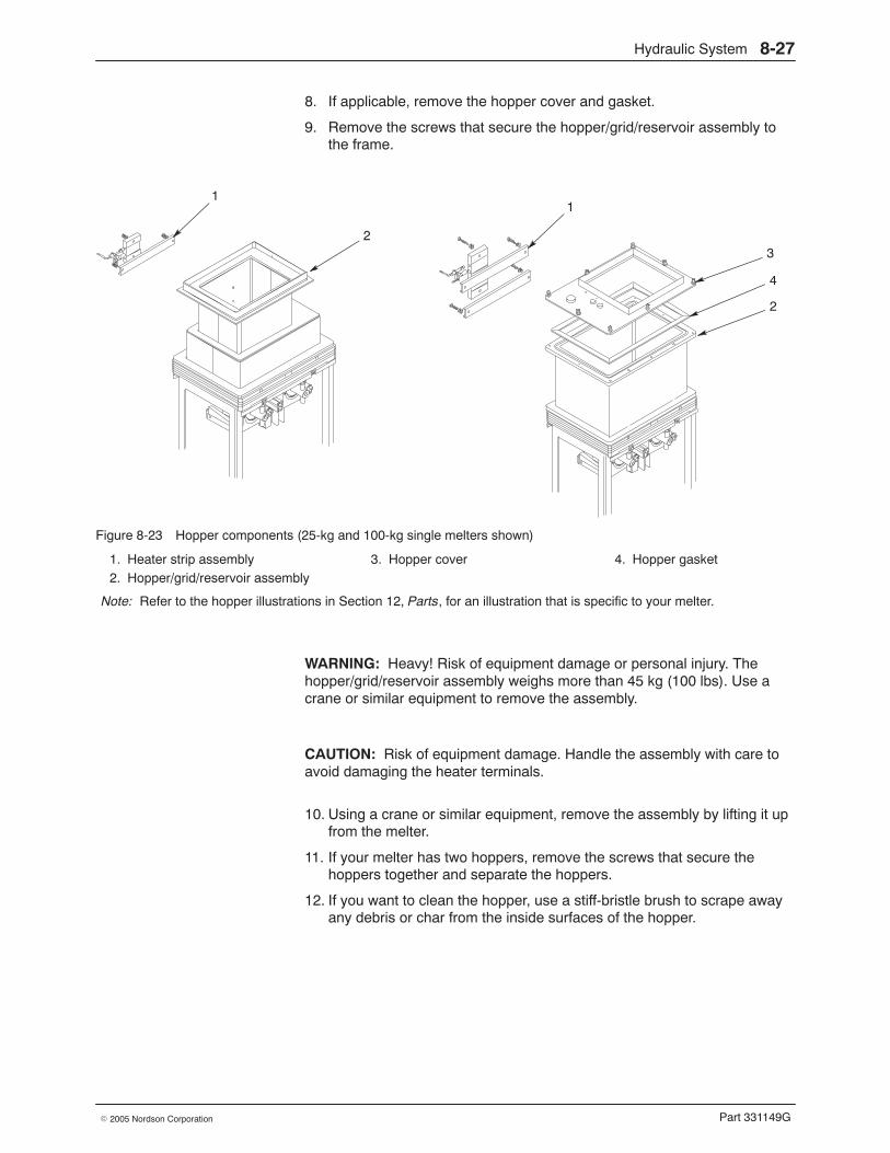
Hydraulic System 8-27
Part 331149G� 2005 Nordson Corporation
8. If applicable, remove the hopper cover and gasket.
9. Remove the screws that secure the hopper/grid/reservoir assembly tothe frame.
1
23
4
2
1
Figure 8-23 Hopper components (25-kg and 100-kg single melters shown)
1. Heater strip assembly2. Hopper/grid/reservoir assembly
3. Hopper cover 4. Hopper gasket
Note: Refer to the hopper illustrations in Section 12, Parts, for an illustration that is specific to your melter.
WARNING: Heavy! Risk of equipment damage or personal injury. Thehopper/grid/reservoir assembly weighs more than 45 kg (100 lbs). Use acrane or similar equipment to remove the assembly.
CAUTION: Risk of equipment damage. Handle the assembly with care toavoid damaging the heater terminals.
10. Using a crane or similar equipment, remove the assembly by lifting it upfrom the melter.
11. If your melter has two hoppers, remove the screws that secure thehoppers together and separate the hoppers.
12. If you want to clean the hopper, use a stiff-bristle brush to scrape awayany debris or char from the inside surfaces of the hopper.
Hydraulic System8-28
Part 331149G � 2005 Nordson Corporation
Install the Assembly NOTE: Apply anti-seize lubricant to all straight threads.
1. If applicable, position the hopper seal between the hoppers and securethe hoppers with the screws removed previously. Inspect the seal fordamage and replace if necessary. Tighten the hopper-to-hopper screwsto 24 N�m (212 in.-lb).
2. Using a crane or similar equipment, position the hopper/grid/reservoirassembly on the melter frame and secure it with the screws removedpreviously. Tighten the screws to 48 N�m (425 in.-lb).
3. If applicable, reinstall the hopper gasket and cover. Apply red RTVsealant to the gasket.
4. Reinstall the insulation.
5. Reinstall the hopper heater strip assembly.
6. Reconnect the heaters and sensors.
7. Reinstall all melter panels.
8. Reinstall the melter cover.
9. Restore the system to normal operation.
Removing and Installing a Manifold Follow this procedure to remove and install a manifold. You may need toremove a manifold to replace the manifold or to replace only a manifoldheater plate. If you need to replace the manifold, Nordson Corporationrecommends ordering a complete manifold assembly with all manifoldcomponents (such as valves and plugs) already installed. You will need thefollowing items:
� drain pans� appropriate tools� replacement manifold assembly (if needed)
NOTE: To change from a single-stream to a dual-stream manifold (or viceverse) or to remove or add a manifold, refer to Upgrading/Downgrading aManifold Position later in this section.
Remove the Manifold 1. Disconnect and lock out electrical power to the system. Refer to
Removing Power in Section 6, Maintenance, as needed.
2. Remove the hopper-side and manifold-side panels. Refer to Removing aPanel in Section 6, Maintenance, as needed.
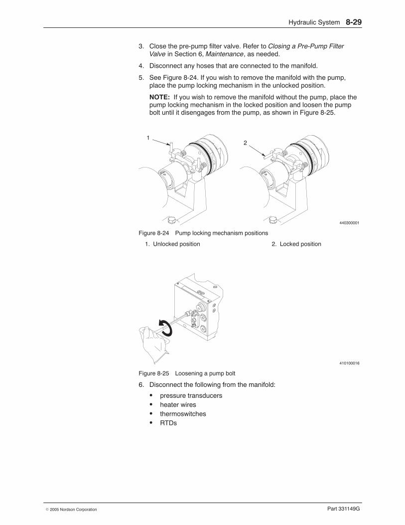
Hydraulic System 8-29
Part 331149G� 2005 Nordson Corporation
3. Close the pre-pump filter valve. Refer to Closing a Pre-Pump FilterValve in Section 6, Maintenance, as needed.
4. Disconnect any hoses that are connected to the manifold.
5. See Figure 8-24. If you wish to remove the manifold with the pump,place the pump locking mechanism in the unlocked position.
NOTE: If you wish to remove the manifold without the pump, place thepump locking mechanism in the locked position and loosen the pumpbolt until it disengages from the pump, as shown in Figure 8-25.
440300001
12
Figure 8-24 Pump locking mechanism positions
1. Unlocked position 2. Locked position
410100016
Figure 8-25 Loosening a pump bolt
6. Disconnect the following from the manifold:
� pressure transducers� heater wires� thermoswitches� RTDs
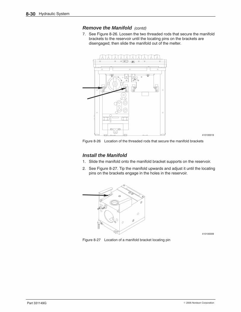
Hydraulic System8-30
Part 331149G � 2005 Nordson Corporation
Remove the Manifold (contd)
7. See Figure 8-26. Loosen the two threaded rods that secure the manifoldbrackets to the reservoir until the locating pins on the brackets aredisengaged; then slide the manifold out of the melter.
410100019
Figure 8-26 Location of the threaded rods that secure the manifold brackets
Install the Manifold 1. Slide the manifold onto the manifold bracket supports on the reservoir.
2. See Figure 8-27. Tip the manifold upwards and adjust it until the locatingpins on the brackets engage in the holes in the reservoir.
410100009
Figure 8-27 Location of a manifold bracket locating pin
Hydraulic System 8-31
Part 331149G� 2005 Nordson Corporation
3. While keeping the locating pins engaged, tighten the threaded rods (seeFigure 8-26) that secure the manifold brackets to the reservoir. Themanifold should raise up and seat properly under the reservoir.
NOTE: If the locating pins are not properly engaged, the manifold willslide forward as you try to tighten the threaded rods.
4. Connect the following to the manifold:
� pressure transducers� heater wires� thermoswitches� RTDs� hoses
5. If the manifold was removed without the pump, tighten the pump bolt to17 N�m (12−13 ft-lb) to secure the pump to the manifold.
6. Place the pump locking mechanism in the locked position.
7. Open the pre-pump filter valve, reinstall the panels, and restore thesystem to normal operation.
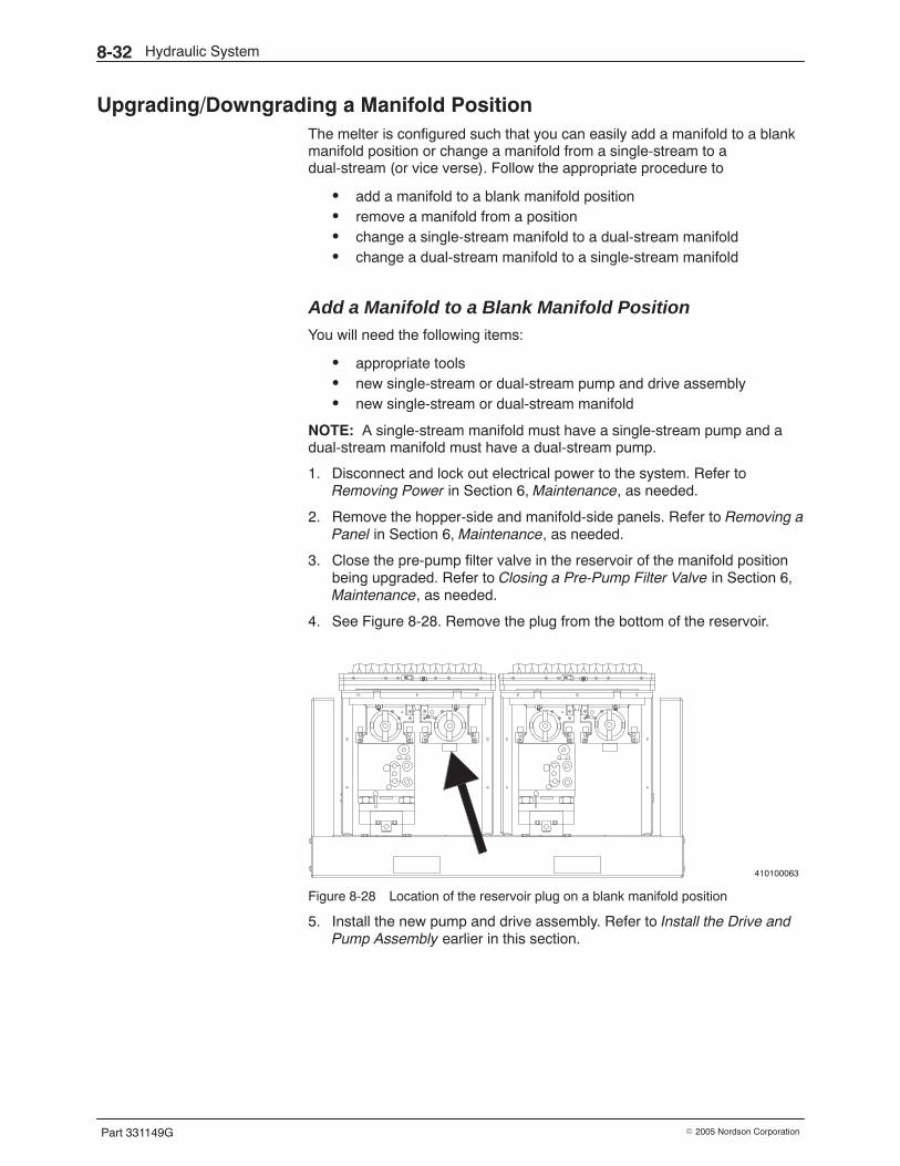
Hydraulic System8-32
Part 331149G � 2005 Nordson Corporation
Upgrading/Downgrading a Manifold Position The melter is configured such that you can easily add a manifold to a blankmanifold position or change a manifold from a single-stream to adual-stream (or vice verse). Follow the appropriate procedure to
� add a manifold to a blank manifold position� remove a manifold from a position� change a single-stream manifold to a dual-stream manifold� change a dual-stream manifold to a single-stream manifold
Add a Manifold to a Blank Manifold Position You will need the following items:
� appropriate tools� new single-stream or dual-stream pump and drive assembly� new single-stream or dual-stream manifold
NOTE: A single-stream manifold must have a single-stream pump and adual-stream manifold must have a dual-stream pump.
1. Disconnect and lock out electrical power to the system. Refer toRemoving Power in Section 6, Maintenance, as needed.
2. Remove the hopper-side and manifold-side panels. Refer to Removing aPanel in Section 6, Maintenance, as needed.
3. Close the pre-pump filter valve in the reservoir of the manifold positionbeing upgraded. Refer to Closing a Pre-Pump Filter Valve in Section 6,Maintenance, as needed.
4. See Figure 8-28. Remove the plug from the bottom of the reservoir.
410100063
Figure 8-28 Location of the reservoir plug on a blank manifold position
5. Install the new pump and drive assembly. Refer to Install the Drive andPump Assembly earlier in this section.
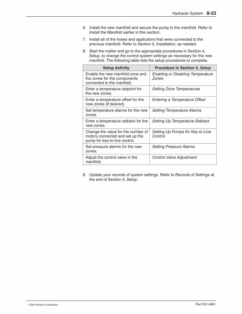
Hydraulic System 8-33
Part 331149G� 2005 Nordson Corporation
6. Install the new manifold and secure the pump to the manifold. Refer toInstall the Manifold earlier in this section.
7. Install all of the hoses and applicators that were connected to theprevious manifold. Refer to Section 3, Installation, as needed.
8. Start the melter and go to the appropriate procedures in Section 4,Setup, to change the control system settings as necessary for the newmanifold. The following table lists the setup procedures to complete.
Setup Activity Procedure in Section 4, Setup
Enable the new manifold zone andthe zones for the componentsconnected to the manifold.
Enabling or Disabling TemperatureZones
Enter a temperature setpoint forthe new zones.
Setting Zone Temperatures
Enter a temperature offset for thenew zones (if desired).
Entering a Temperature Offset
Set temperature alarms for the newzones.
Setting Temperature Alarms
Enter a temperature setback for thenew zones.
Setting Up Temperature Setback
Change the value for the number ofmotors connected and set up thepump for key-to-line control.
Setting Up Pumps for Key-to-LineControl
Set pressure alarms for the newzones.
Setting Pressure Alarms
Adjust the control valve in themanifold.
Control Valve Adjustment
9. Update your records of system settings. Refer to Records of Settings atthe end of Section 4, Setup.
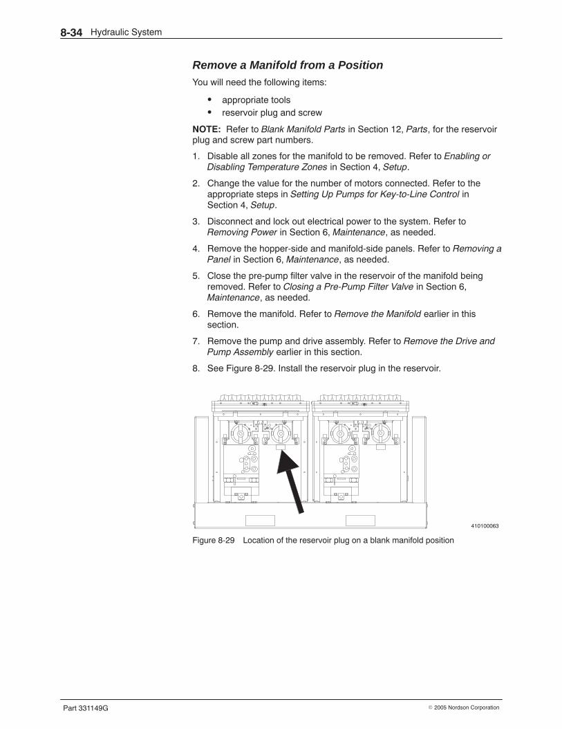
Hydraulic System8-34
Part 331149G � 2005 Nordson Corporation
Remove a Manifold from a Position You will need the following items:
� appropriate tools� reservoir plug and screw
NOTE: Refer to Blank Manifold Parts in Section 12, Parts, for the reservoirplug and screw part numbers.
1. Disable all zones for the manifold to be removed. Refer to Enabling orDisabling Temperature Zones in Section 4, Setup.
2. Change the value for the number of motors connected. Refer to theappropriate steps in Setting Up Pumps for Key-to-Line Control inSection 4, Setup.
3. Disconnect and lock out electrical power to the system. Refer toRemoving Power in Section 6, Maintenance, as needed.
4. Remove the hopper-side and manifold-side panels. Refer to Removing aPanel in Section 6, Maintenance, as needed.
5. Close the pre-pump filter valve in the reservoir of the manifold beingremoved. Refer to Closing a Pre-Pump Filter Valve in Section 6,Maintenance, as needed.
6. Remove the manifold. Refer to Remove the Manifold earlier in thissection.
7. Remove the pump and drive assembly. Refer to Remove the Drive andPump Assembly earlier in this section.
8. See Figure 8-29. Install the reservoir plug in the reservoir.
410100063
Figure 8-29 Location of the reservoir plug on a blank manifold position
Hydraulic System 8-35
Part 331149G� 2005 Nordson Corporation
Change a Manifold from Single to Dual or Dual to Single You will need the following items:
� appropriate tools� new single-stream or dual-stream pump and drive assembly� new single-stream or dual-stream manifold
NOTE: A single-stream manifold must have a single-stream pump and adual-stream manifold must have a dual-stream pump.
1. Disconnect and lock out electrical power to the system. Refer toRemoving Power in Section 6, Maintenance, as needed.
2. Remove the hopper-side and manifold-side panels. Refer to Removing aPanel in Section 6, Maintenance, as needed.
3. Close the pre-pump filter valve in the reservoir of the manifold positionbeing upgraded. Refer to Closing a Pre-Pump Filter Valve in Section 6,Maintenance, as needed.
4. Remove the drive and pump assembly of the manifold to beupgraded/downgraded. Refer to Remove the Drive and Pump Assemblyearlier in this section.
5. Install a new drive and pump assembly for the new manifold to beinstalled. Refer to Install the Drive and Pump Assembly earlier in thissection.
NOTE: A single-stream manifold must have a single-stream pump anda dual-stream manifold must have a dual-stream pump.
6. Remove the manifold to be upgraded/downgraded. Refer to Remove theManifold earlier in this section.
7. Install the new manifold and secure the pump to the manifold. Refer toInstall the Manifold earlier in this section.
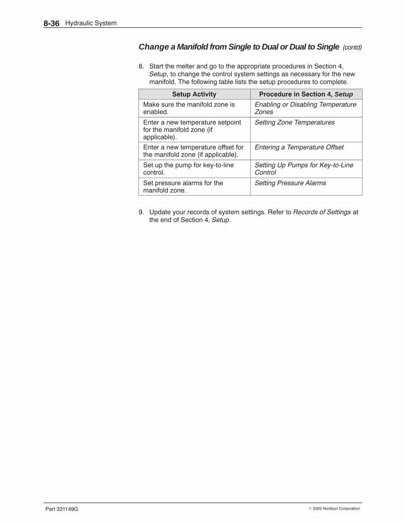
Hydraulic System8-36
Part 331149G � 2005 Nordson Corporation
Change a Manifold from Single to Dual or Dual to Single (contd)
8. Start the melter and go to the appropriate procedures in Section 4,Setup, to change the control system settings as necessary for the newmanifold. The following table lists the setup procedures to complete.
Setup Activity Procedure in Section 4, Setup
Make sure the manifold zone isenabled.
Enabling or Disabling TemperatureZones
Enter a new temperature setpointfor the manifold zone (ifapplicable).
Setting Zone Temperatures
Enter a new temperature offset forthe manifold zone (if applicable).
Entering a Temperature Offset
Set up the pump for key-to-linecontrol.
Setting Up Pumps for Key-to-LineControl
Set pressure alarms for themanifold zone.
Setting Pressure Alarms
9. Update your records of system settings. Refer to Records of Settings atthe end of Section 4, Setup.
Drive System 9-1
Part 331149G� 2005 Nordson Corporation
Section 9Drive System
WARNING: Allow only personnel with appropriate training and experienceto operate or service the equipment. The use of untrained or inexperiencedpersonnel to operate or service the equipment can result in injury, includingdeath, to themselves and others, and damage to the equipment.
Introduction The section contains troubleshooting and repair procedures for the melter’sdrive system, which includes all motors and reducers present on the melter.
Troubleshooting of the drive system begins when the control systemprovides an alarm or when a motor fails to start, stops, or runs erratically. Ifyou try all the troubleshooting suggestions in this section and still cannotsolve the problem, contact your Nordson representative for assistance.
Other troubleshooting information in this manual is located as follows:
� For temperature control problems, such as a non-heating oroverheating zone, refer to Section 7, Temperature Control System.
� For hydraulic system problems, such as too much or too littleadhesive output, refer to Section 8, Hydraulic System.
� For system pressure problems, such as excessively high or lowsystem pressure, refer to Section 10, Pressure Monitoring.
� For level control problems, refer to Section 11, Level Control Option.
� For applicator or adhesive pattern problems, refer to the applicatormanual.
You will need a sufficient inventory of spare parts and supplies. Each repairprocedure is proceeded by a list of the parts and supplies you will need.Refer to Section 12, Parts, for the part numbers for all parts and supplies.
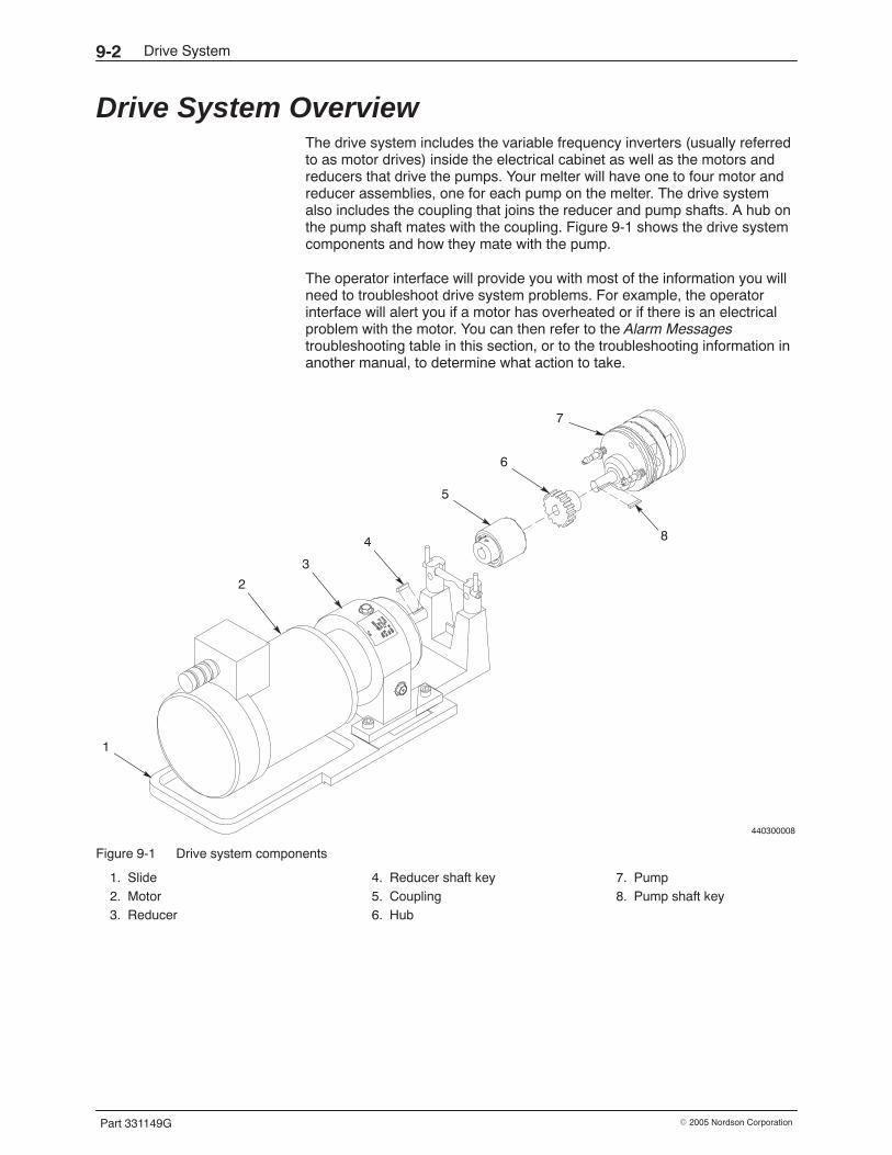
Drive System9-2
Part 331149G � 2005 Nordson Corporation
Drive System Overview The drive system includes the variable frequency inverters (usually referredto as motor drives) inside the electrical cabinet as well as the motors andreducers that drive the pumps. Your melter will have one to four motor andreducer assemblies, one for each pump on the melter. The drive systemalso includes the coupling that joins the reducer and pump shafts. A hub onthe pump shaft mates with the coupling. Figure 9-1 shows the drive systemcomponents and how they mate with the pump.
The operator interface will provide you with most of the information you willneed to troubleshoot drive system problems. For example, the operatorinterface will alert you if a motor has overheated or if there is an electricalproblem with the motor. You can then refer to the Alarm Messagestroubleshooting table in this section, or to the troubleshooting information inanother manual, to determine what action to take.
440300008
7
6
5
4
3
2
1
8
Figure 9-1 Drive system components
1. Slide2. Motor3. Reducer
4. Reducer shaft key5. Coupling6. Hub
7. Pump8. Pump shaft key
Drive System 9-3
Part 331149G� 2005 Nordson Corporation
Troubleshooting Tables The troubleshooting tables in this section describe the kinds of drive systemproblems you may encounter and provide corrective actions for solvingthose problems. Refer to the appropriate troubleshooting table for the typeof problem you are experiencing:
� Alarm Messages� Drive System Problems
WARNING: Always wear heat-protective clothing, goggles (ANSI Z87.1 orequivalent), and safety gloves when working with hot melt equipment.
WARNING: Risk of equipment damage, personal injury, or death. Onlyqualifed personnel may perform electrical troubleshooting activities. Followelectrical safety procedures and observe all high-voltage indicators.
WARNING: Before performing any electrical troubleshooting activity,disconnect and lock out electrical power as appropriate. Refer to RemovingPower in Section 6, Maintenance.
Drive System9-4
Part 331149G � 2005 Nordson Corporation
Alarm Messages Anytime an alarm occurs during the operation of the melter, the controlsystem will display an alarm message on the alarm screen andautomatically take the appropriate action. Depending on how serious thealarm is, the system will respond appropriately, as shown in Table 9-1.Table 9-2 provides troubleshooting advice for each type of alarm message.
NOTE: These alarm messages are typical for a standard PanelMate orPanelView operator interface. The operator interface for your control systemmay differ.
NOTE: For ACM alarm message troubleshooting, refer to the ACM manual.
Table 9-1 Types of Drive System Alarms and Resulting System Response
Fault Alarms System Response
� Frequency Inverter Fault
� Overtemperature
Removes the run-permissive signal from the pumps,disabling the pumps. Continues to heat all enabled zones
Table 9-2 Troubleshooting Advice for Drive System Alarms
Alarm Message Explanation Recommended Action
[Name of Zone]FrequencyInverter Fault
The variable frequency inverter hastripped. This is usually caused by athermal fault or undervoltagecondition, but there are many otherpossible causes.
Check within the drive to determine the faultcode. The fault code will indicate whatcaused the inverter to trip. Correct theproblem or replace the inverter asappropriate.
[Name of Zone]Overtemperature
The motor has overheated. Check for the following problems:
� blockages in the system
� failed reducer
Drive System 9-5
Part 331149G� 2005 Nordson Corporation
Drive System Problems
Problem Possible Cause Corrective Action
1. Motor stops or fails tostart
No power to melter Make sure the melter is powered on.
Motor disconnect switch in OFFposition
Place the motor disconnect switch onthe front of the melter in the ONposition.
System-ready condition not yetreached
Wait for the system to reachapplication temperature.
Loose line speed sensorconnections
Check the line speed sensor wiringconnections.
Failed line speed sensor Check the line speed sensor forcontinuity. If the circuit is open, checkthe connections or replace the linespeed sensor.
Plugged output at one or morepositions
Check for blockage in a manifold orhose. Check for a cold hose.
Pump binding or locking up Check the pump and replace it ifnecessary. Refer to Replacing aPump in Section 8, Hydraulic System.
Coupling or shaft key (pump orreducer) broken
Replace the coupling and/or key.Refer to Drive Assembly ComponentReplacement in this section.
Failed reducer (if reducer shaft isnot rotating)
Replace the reducer. Refer to DriveAssembly Component Replacementin this section.
2. Motor runningerratically
Failed motor Measure the resistance across themotor windings. If an open circuit isindicated, replace the motor. Refer toDrive Assembly ComponentReplacement in this section.
Motor locked out by control system Test the motor, repair or replace asnecessary, and reset the controlsystem.
Drive System9-6
Part 331149G � 2005 Nordson Corporation
Drive Assembly Component Replacement Troubleshooting may identify needed repairs. This part of Section 9 containsprocedures for
� removing a drive assembly� replacing a drive assembly component� installing a drive assembly
These procedures require some special knowledge. Procedures that can beeasily performed without special knowledge, such as replacing a cable, arenot included. Before performing any repair, be sure to
� Review Section 1, Safety.
� Have the required parts and supplies on hand. They are listed at thebeginning of each procedure.
� Refer to the illustrations in Section 12, Parts, as needed forreplacement part numbers and detailed parts lists and illustrations ofthe melter components.
WARNING: Always wear heat-protective clothing, goggles (ANSI Z87.1 orequivalent), and safety gloves when working with hot melt equipment.
WARNING: Before performing any repair, relieve system pressure. Refer toRelieving System Pressure in Section 6, Maintenance.
WARNING: Before performing any repair, disconnect and lock out electricalpower as appropriate. Refer to Removing Power in Section 6, Maintenance.
Removing a Drive Assembly Follow this procedure to remove a drive assembly. This procedure allowsyou remove the drive assembly without removing the pump.
NOTE: The procedure for removing the drive assembly along with thepump is located in Section 8, Hydraulic System.
1. Stop all pump motors internal and external to the melter.
2. Disconnect and lock out electrical power to the melter. Refer toRemoving Power in Section 6, Maintenance.
3. Remove the motor-side panel of the melter. Refer to Removing a Panelin Section 6, Maintenance.
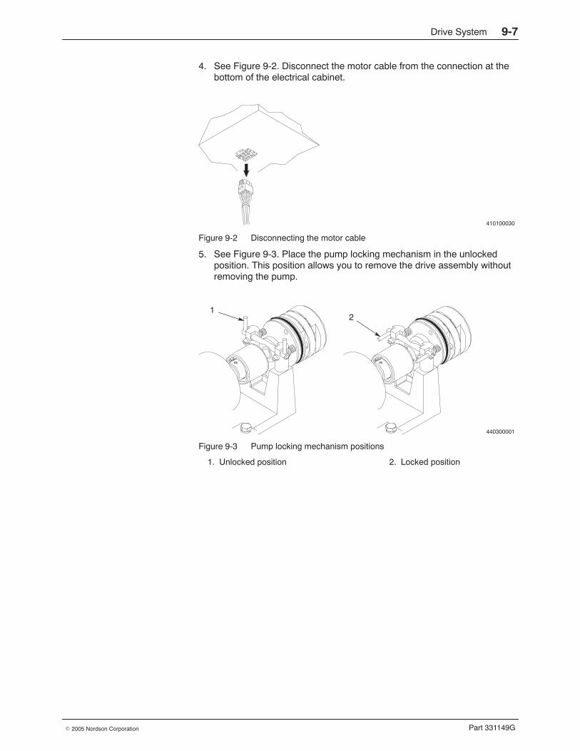
Drive System 9-7
Part 331149G� 2005 Nordson Corporation
4. See Figure 9-2. Disconnect the motor cable from the connection at thebottom of the electrical cabinet.
410100030
Figure 9-2 Disconnecting the motor cable
5. See Figure 9-3. Place the pump locking mechanism in the unlockedposition. This position allows you to remove the drive assembly withoutremoving the pump.
440300001
12
Figure 9-3 Pump locking mechanism positions
1. Unlocked position 2. Locked position
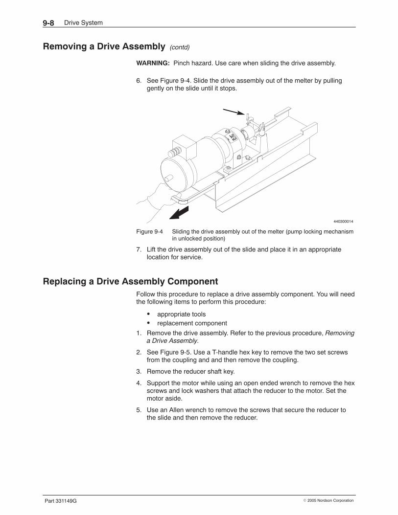
Drive System9-8
Part 331149G � 2005 Nordson Corporation
Removing a Drive Assembly (contd)
WARNING: Pinch hazard. Use care when sliding the drive assembly.
6. See Figure 9-4. Slide the drive assembly out of the melter by pullinggently on the slide until it stops.
440300014
Figure 9-4 Sliding the drive assembly out of the melter (pump locking mechanismin unlocked position)
7. Lift the drive assembly out of the slide and place it in an appropriatelocation for service.
Replacing a Drive Assembly Component Follow this procedure to replace a drive assembly component. You will needthe following items to perform this procedure:
� appropriate tools� replacement component
1. Remove the drive assembly. Refer to the previous procedure, Removinga Drive Assembly.
2. See Figure 9-5. Use a T-handle hex key to remove the two set screwsfrom the coupling and and then remove the coupling.
3. Remove the reducer shaft key.
4. Support the motor while using an open ended wrench to remove the hexscrews and lock washers that attach the reducer to the motor. Set themotor aside.
5. Use an Allen wrench to remove the screws that secure the reducer tothe slide and then remove the reducer.
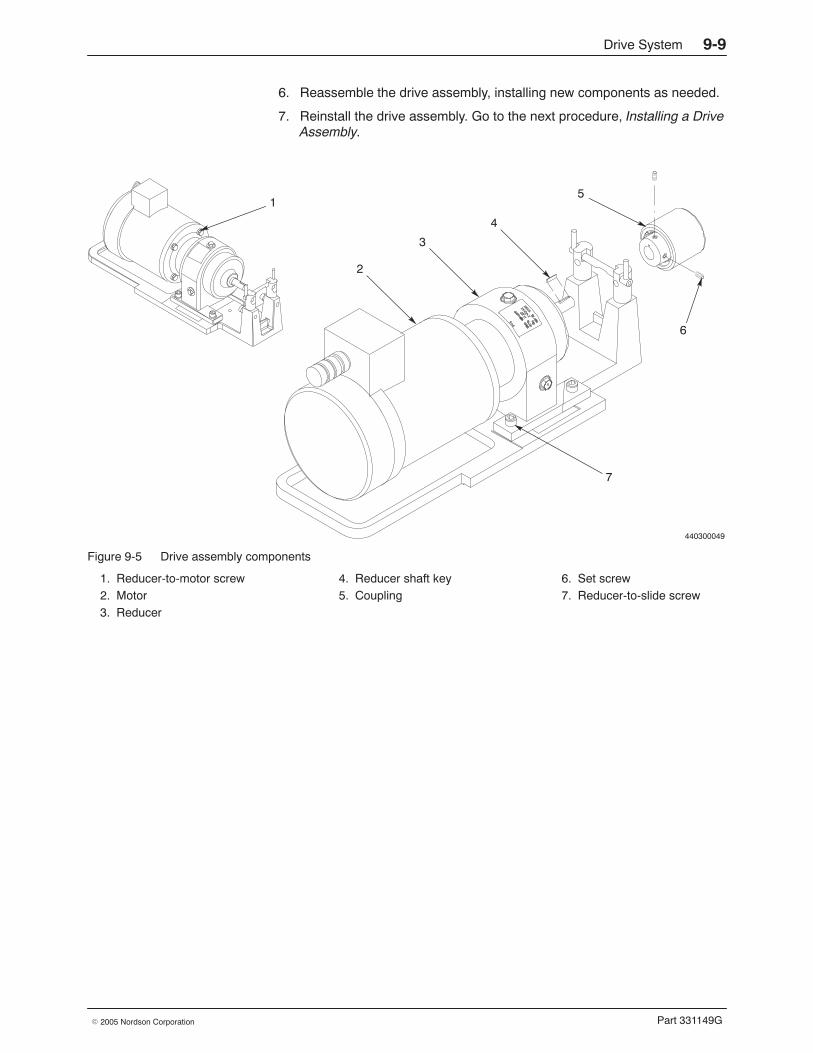
Drive System 9-9
Part 331149G� 2005 Nordson Corporation
6. Reassemble the drive assembly, installing new components as needed.
7. Reinstall the drive assembly. Go to the next procedure, Installing a DriveAssembly.
440300049
1
2
3
4
5
6
7
Figure 9-5 Drive assembly components
1. Reducer-to-motor screw2. Motor3. Reducer
4. Reducer shaft key5. Coupling
6. Set screw7. Reducer-to-slide screw
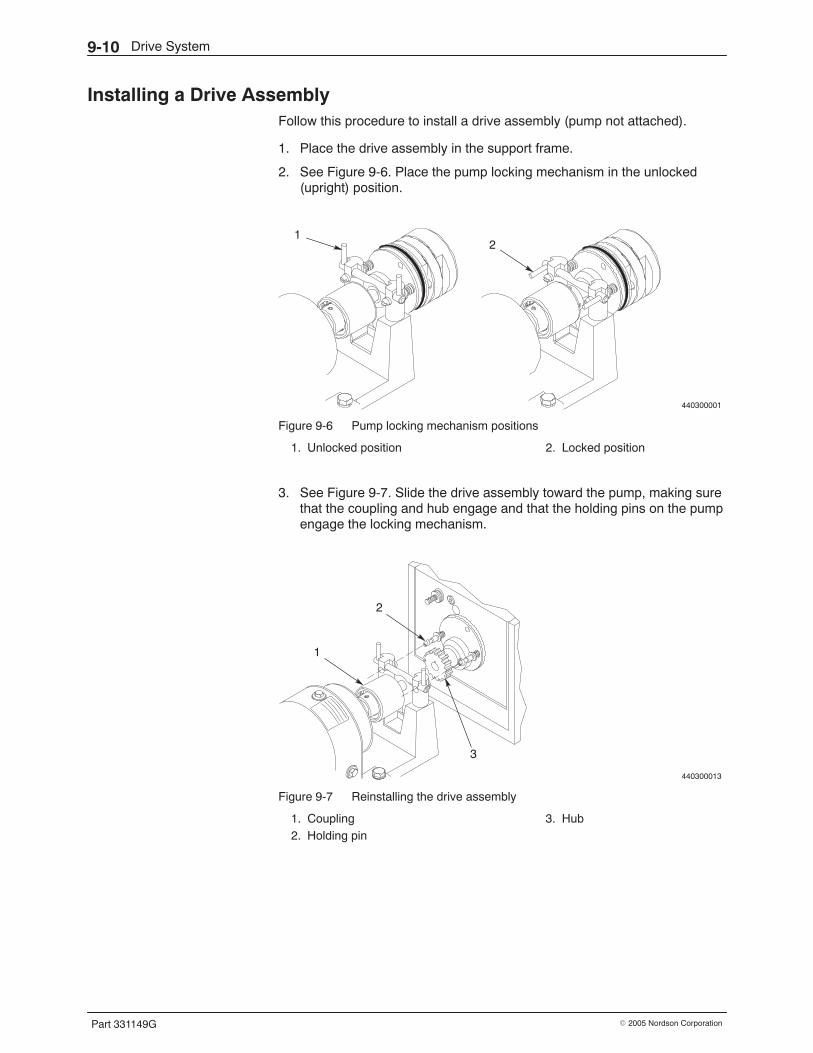
Drive System9-10
Part 331149G � 2005 Nordson Corporation
Installing a Drive Assembly Follow this procedure to install a drive assembly (pump not attached).
1. Place the drive assembly in the support frame.
2. See Figure 9-6. Place the pump locking mechanism in the unlocked(upright) position.
440300001
12
Figure 9-6 Pump locking mechanism positions
1. Unlocked position 2. Locked position
3. See Figure 9-7. Slide the drive assembly toward the pump, making surethat the coupling and hub engage and that the holding pins on the pumpengage the locking mechanism.
440300013
1
2
3
Figure 9-7 Reinstalling the drive assembly
1. Coupling2. Holding pin
3. Hub
Drive System 9-11
Part 331149G� 2005 Nordson Corporation
4. Place the pump locking mechanism in the locked position.
5. Reconnect the motor cable to the connection on the bottom of theelectrical cabinet.
6. Reinstall the motor-side panel and restore the system to normaloperation.

Drive System9-12
Part 331149G � 2005 Nordson Corporation
Pressure Monitoring 10-1
Part 331149G� 2005 Nordson Corporation
Section 10Pressure Monitoring
WARNING: Allow only personnel with appropriate training and experienceto operate or service the equipment. The use of untrained or inexperiencedpersonnel to operate or service the equipment can result in injury, includingdeath, to themselves and others, and damage to the equipment.
Introduction This section provides troubleshooting and repair information for the melter’spressure monitoring function. Pressure monitoring is accomplished throughthe pressure transducer(s) installed in each melter manifold.
Troubleshooting of the pressure monitoring function begins when the controlsystem provides an over- or under-pressure alarm or when a pressurereading is faulty. If you try all the troubleshooting suggestions in this sectionand still cannot solve the problem, contact your Nordson representative forassistance.
Other troubleshooting information in this manual is located as follows:
� For temperature control problems, such as a non-heating oroverheating component, refer to Section 7, Temperature ControlSystem.
� For hydraulic system problems, such as too much or too littleadhesive output, refer to Section 8, Hydraulic System.
� For drive system problems, such as a failed motor, refer toSection 9, Drive System.
� For level control problems, refer to Section 11, Level Control Option.
� For applicator or adhesive pattern problems, refer to the applicatormanual.
You will need a sufficient inventory of spare parts and supplies. Each repairprocedure is preceded by a list of the parts and supplies you will need.Refer to Section 12, Parts, for the part numbers for all parts and supplies.
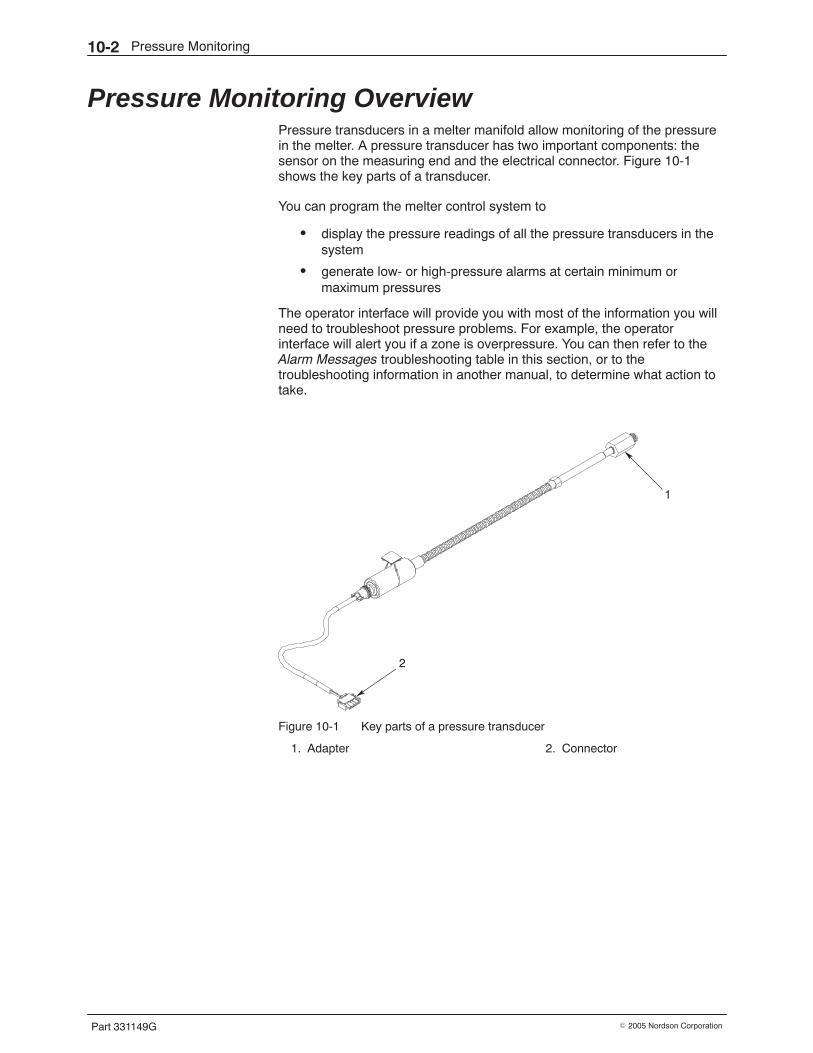
Pressure Monitoring10-2
Part 331149G � 2005 Nordson Corporation
Pressure Monitoring Overview Pressure transducers in a melter manifold allow monitoring of the pressurein the melter. A pressure transducer has two important components: thesensor on the measuring end and the electrical connector. Figure 10-1shows the key parts of a transducer.
You can program the melter control system to
� display the pressure readings of all the pressure transducers in thesystem
� generate low- or high-pressure alarms at certain minimum ormaximum pressures
The operator interface will provide you with most of the information you willneed to troubleshoot pressure problems. For example, the operatorinterface will alert you if a zone is overpressure. You can then refer to theAlarm Messages troubleshooting table in this section, or to thetroubleshooting information in another manual, to determine what action totake.
1
2
Figure 10-1 Key parts of a pressure transducer
1. Adapter 2. Connector
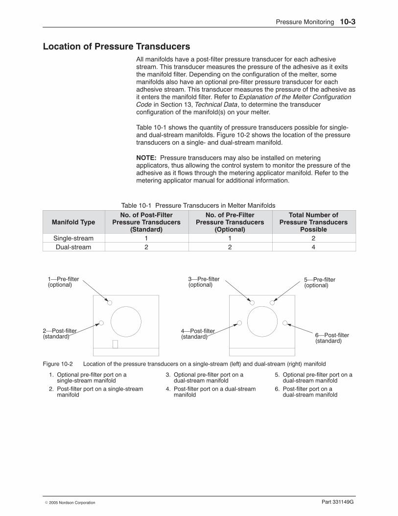
Pressure Monitoring 10-3
Part 331149G� 2005 Nordson Corporation
Location of Pressure Transducers All manifolds have a post-filter pressure transducer for each adhesivestream. This transducer measures the pressure of the adhesive as it exitsthe manifold filter. Depending on the configuration of the melter, somemanifolds also have an optional pre-filter pressure transducer for eachadhesive stream. This transducer measures the pressure of the adhesive asit enters the manifold filter. Refer to Explanation of the Melter ConfigurationCode in Section 13, Technical Data, to determine the transducerconfiguration of the manifold(s) on your melter.
Table 10-1 shows the quantity of pressure transducers possible for single-and dual-stream manifolds. Figure 10-2 shows the location of the pressuretransducers on a single- and dual-stream manifold.
NOTE: Pressure transducers may also be installed on meteringapplicators, thus allowing the control system to monitor the pressure of theadhesive as it flows through the metering applicator manifold. Refer to themetering applicator manual for additional information.
Table 10-1 Pressure Transducers in Melter Manifolds
Manifold TypeNo. of Post-Filter
Pressure Transducers(Standard)
No. of Pre-FilterPressure Transducers
(Optional)
Total Number ofPressure Transducers
PossibleSingle-stream 1 1 2Dual-stream 2 2 4
2—Post-filter
3—Pre-filter
6—Post-filter(standard)(standard)
4—Post-filter(standard)
1—Pre-filter(optional) (optional)
5—Pre-filter(optional)
Figure 10-2 Location of the pressure transducers on a single-stream (left) and dual-stream (right) manifold
1. Optional pre-filter port on asingle-stream manifold
2. Post-filter port on a single-streammanifold
3. Optional pre-filter port on adual-stream manifold
4. Post-filter port on a dual-streammanifold
5. Optional pre-filter port on adual-stream manifold
6. Post-filter port on adual-stream manifold
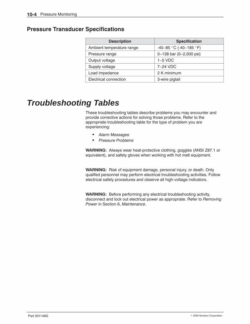
Pressure Monitoring10-4
Part 331149G � 2005 Nordson Corporation
Pressure Transducer Specifications
Description Specification
Ambient temperature range -40−85 �C (-40−185 �F)
Pressure range 0−138 bar (0−2,000 psi)
Output voltage 1−5 VDC
Supply voltage 7−24 VDC
Load impedance 2 K minimum
Electrical connection 3-wire pigtail
Troubleshooting Tables These troubleshooting tables describe problems you may encounter andprovide corrective actions for solving those problems. Refer to theappropriate troubleshooting table for the type of problem you areexperiencing:
� Alarm Messages� Pressure Problems
WARNING: Always wear heat-protective clothing, goggles (ANSI Z87.1 orequivalent), and safety gloves when working with hot melt equipment.
WARNING: Risk of equipment damage, personal injury, or death. Onlyqualifed personnel may perform electrical troubleshooting activities. Followelectrical safety procedures and observe all high-voltage indicators.
WARNING: Before performing any electrical troubleshooting activity,disconnect and lock out electrical power as appropriate. Refer to RemovingPower in Section 6, Maintenance.
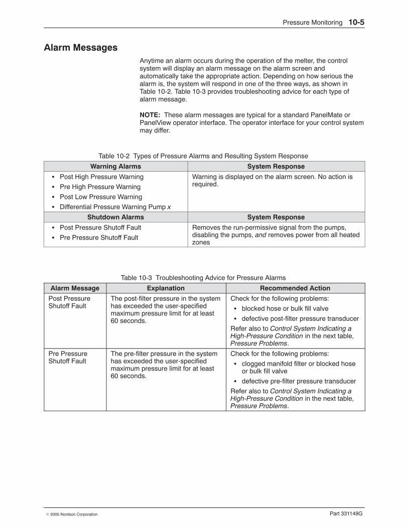
Pressure Monitoring 10-5
Part 331149G� 2005 Nordson Corporation
Alarm Messages Anytime an alarm occurs during the operation of the melter, the controlsystem will display an alarm message on the alarm screen andautomatically take the appropriate action. Depending on how serious thealarm is, the system will respond in one of the three ways, as shown inTable 10-2. Table 10-3 provides troubleshooting advice for each type ofalarm message.
NOTE: These alarm messages are typical for a standard PanelMate orPanelView operator interface. The operator interface for your control systemmay differ.
Table 10-2 Types of Pressure Alarms and Resulting System Response
Warning Alarms System Response
� Post High Pressure Warning
� Pre High Pressure Warning
� Post Low Pressure Warning
� Differential Pressure Warning Pump x
Warning is displayed on the alarm screen. No action isrequired.
Shutdown Alarms System Response
� Post Pressure Shutoff Fault
� Pre Pressure Shutoff Fault
Removes the run-permissive signal from the pumps,disabling the pumps, and removes power from all heatedzones
Table 10-3 Troubleshooting Advice for Pressure Alarms
Alarm Message Explanation Recommended Action
Post PressureShutoff Fault
The post-filter pressure in the systemhas exceeded the user-specifiedmaximum pressure limit for at least60 seconds.
Check for the following problems:
� blocked hose or bulk fill valve
� defective post-filter pressure transducer
Refer also to Control System Indicating aHigh-Pressure Condition in the next table,Pressure Problems.
Pre PressureShutoff Fault
The pre-filter pressure in the systemhas exceeded the user-specifiedmaximum pressure limit for at least60 seconds.
Check for the following problems:
� clogged manifold filter or blocked hoseor bulk fill valve
� defective pre-filter pressure transducer
Refer also to Control System Indicating aHigh-Pressure Condition in the next table,Pressure Problems.
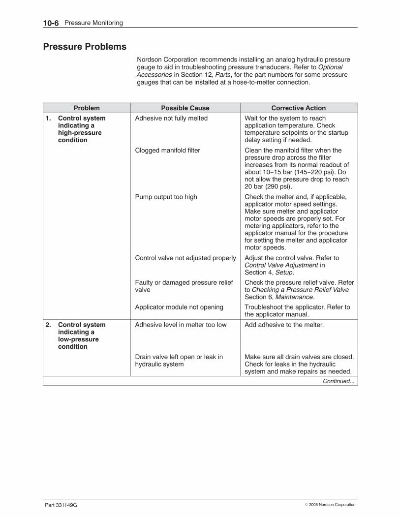
Pressure Monitoring10-6
Part 331149G � 2005 Nordson Corporation
Pressure Problems Nordson Corporation recommends installing an analog hydraulic pressuregauge to aid in troubleshooting pressure transducers. Refer to OptionalAccessories in Section 12, Parts, for the part numbers for some pressuregauges that can be installed at a hose-to-melter connection.
Problem Possible Cause Corrective Action
1. Control systemindicating ahigh-pressurecondition
Adhesive not fully melted Wait for the system to reachapplication temperature. Checktemperature setpoints or the startupdelay setting if needed.
Clogged manifold filter Clean the manifold filter when thepressure drop across the filterincreases from its normal readout ofabout 10−15 bar (145−220 psi). Donot allow the pressure drop to reach20 bar (290 psi).
Pump output too high Check the melter and, if applicable,applicator motor speed settings.Make sure melter and applicatormotor speeds are properly set. Formetering applicators, refer to theapplicator manual for the procedurefor setting the melter and applicatormotor speeds.
Control valve not adjusted properly Adjust the control valve. Refer toControl Valve Adjustment inSection 4, Setup.
Faulty or damaged pressure reliefvalve
Check the pressure relief valve. Referto Checking a Pressure Relief ValveSection 6, Maintenance.
Applicator module not opening Troubleshoot the applicator. Refer tothe applicator manual.
2. Control systemindicating alow-pressurecondition
Adhesive level in melter too low Add adhesive to the melter.
Drain valve left open or leak inhydraulic system
Make sure all drain valves are closed.Check for leaks in the hydraulicsystem and make repairs as needed.
Continued...
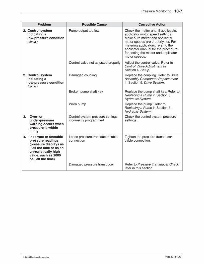
Pressure Monitoring 10-7
Part 331149G� 2005 Nordson Corporation
Corrective ActionPossible CauseProblem
2. Control systemindicating alow-pressure condition(contd.)
Pump output too low Check the melter and, if applicable,applicator motor speed settings.Make sure melter and applicatormotor speeds are properly set. Formetering applicators, refer to theapplicator manual for the procedurefor setting the melter and applicatormotor speeds.
Control valve not adjusted properly Adjust the control valve. Refer toControl Valve Adjustment inSection 4, Setup.
2. Control systemindicating alow-pressure condition(contd.)
Damaged coupling Replace the coupling. Refer to DriveAssembly Component Replacementin Section 9, Drive System.
Broken pump shaft key Replace the pump shaft key. Refer toReplacing a Pump in Section 8,Hydraulic System.
Worn pump Replace the pump. Refer toReplacing a Pump in Section 8,Hydraulic System.
3. Over- orunder-pressurewarning occurs whenpressure is withinlimits
Control system pressure settingsincorrectly programmed
Check the control system pressuresettings.
4. Incorrect or unstablepressure readings(pressure displays as0 all the time or as anunrealistically highvalue, such as 2000psi, all the time)
Loose pressure transducer cableconnection
Tighten the pressure transducercable connection.
Damaged pressure transducer Refer to Pressure Transducer Checklater in this section.
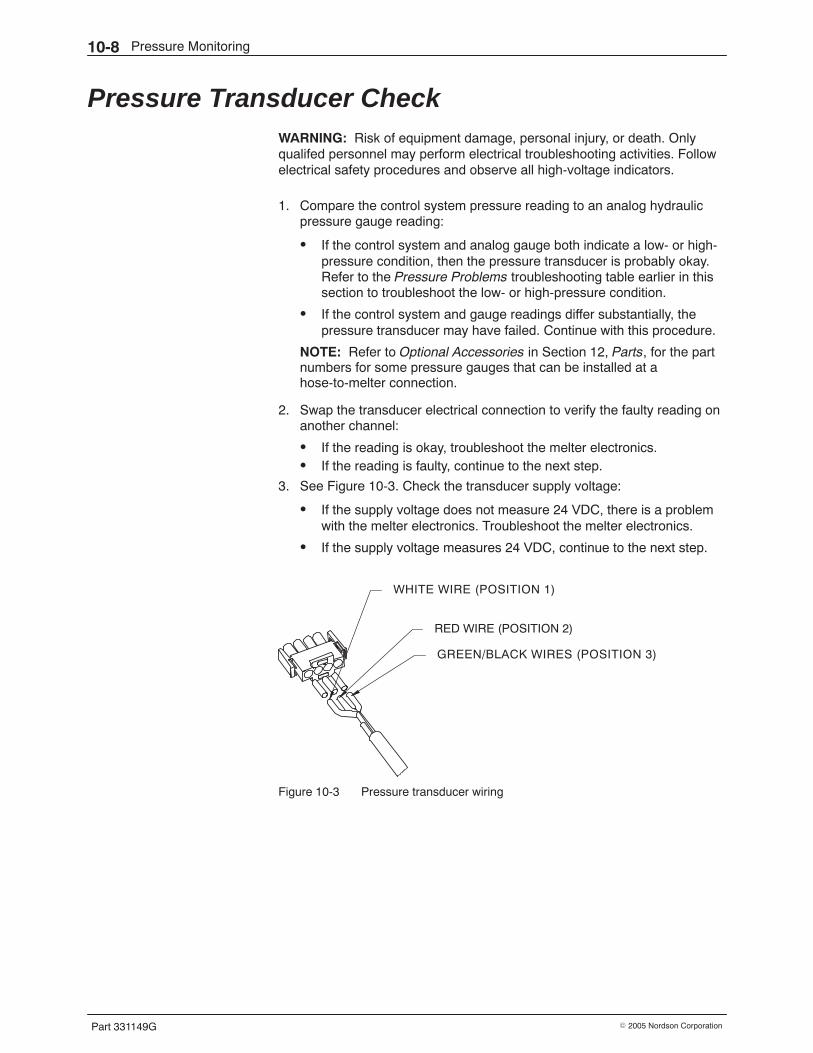
Pressure Monitoring10-8
Part 331149G � 2005 Nordson Corporation
Pressure Transducer Check WARNING: Risk of equipment damage, personal injury, or death. Onlyqualifed personnel may perform electrical troubleshooting activities. Followelectrical safety procedures and observe all high-voltage indicators.
1. Compare the control system pressure reading to an analog hydraulicpressure gauge reading:
� If the control system and analog gauge both indicate a low- or high-pressure condition, then the pressure transducer is probably okay.Refer to the Pressure Problems troubleshooting table earlier in thissection to troubleshoot the low- or high-pressure condition.
� If the control system and gauge readings differ substantially, thepressure transducer may have failed. Continue with this procedure.
NOTE: Refer to Optional Accessories in Section 12, Parts, for the partnumbers for some pressure gauges that can be installed at ahose-to-melter connection.
2. Swap the transducer electrical connection to verify the faulty reading onanother channel:
� If the reading is okay, troubleshoot the melter electronics.� If the reading is faulty, continue to the next step.
3. See Figure 10-3. Check the transducer supply voltage:
� If the supply voltage does not measure 24 VDC, there is a problemwith the melter electronics. Troubleshoot the melter electronics.
� If the supply voltage measures 24 VDC, continue to the next step.
GREEN/BLACK WIRES (POSITION 3)
RED WIRE (POSITION 2)
WHITE WIRE (POSITION 1)
Figure 10-3 Pressure transducer wiring
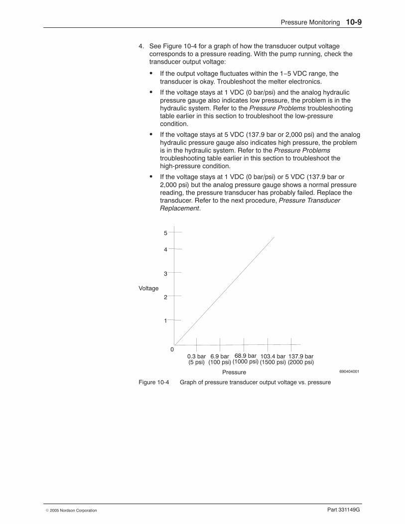
Pressure Monitoring 10-9
Part 331149G� 2005 Nordson Corporation
4. See Figure 10-4 for a graph of how the transducer output voltagecorresponds to a pressure reading. With the pump running, check thetransducer output voltage:
� If the output voltage fluctuates within the 1−5 VDC range, thetransducer is okay. Troubleshoot the melter electronics.
� If the voltage stays at 1 VDC (0 bar/psi) and the analog hydraulicpressure gauge also indicates low pressure, the problem is in thehydraulic system. Refer to the Pressure Problems troubleshootingtable earlier in this section to troubleshoot the low-pressurecondition.
� If the voltage stays at 5 VDC (137.9 bar or 2,000 psi) and the analoghydraulic pressure gauge also indicates high pressure, the problemis in the hydraulic system. Refer to the Pressure Problemstroubleshooting table earlier in this section to troubleshoot thehigh-pressure condition.
� If the voltage stays at 1 VDC (0 bar/psi) or 5 VDC (137.9 bar or2,000 psi) but the analog pressure gauge shows a normal pressurereading, the pressure transducer has probably failed. Replace thetransducer. Refer to the next procedure, Pressure TransducerReplacement.
690404001
Voltage
Pressure
0
1
2
3
4
5
0.3 bar 6.9 bar 68.9 bar 103.4 bar 137.9 bar(5 psi) (100 psi) (1000 psi) (1500 psi) (2000 psi)
Figure 10-4 Graph of pressure transducer output voltage vs. pressure
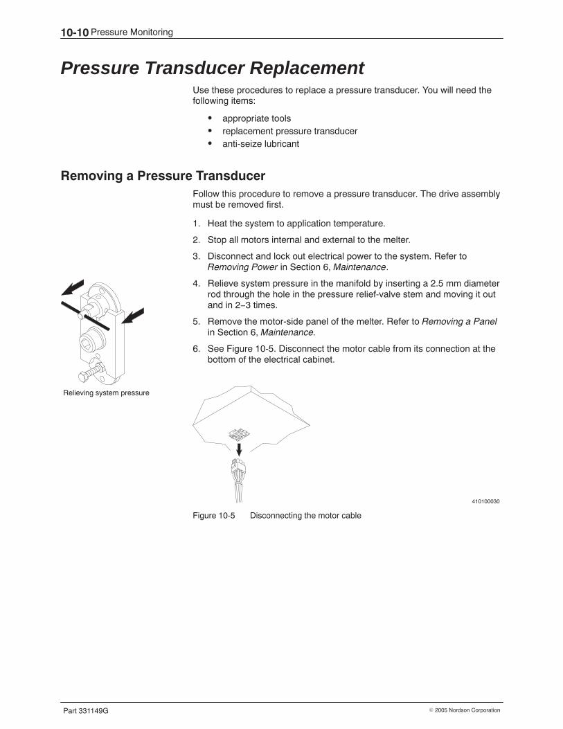
Relieving system pressure
Pressure Monitoring10-10
Part 331149G � 2005 Nordson Corporation
Pressure Transducer Replacement Use these procedures to replace a pressure transducer. You will need thefollowing items:
� appropriate tools� replacement pressure transducer� anti-seize lubricant
Removing a Pressure Transducer Follow this procedure to remove a pressure transducer. The drive assemblymust be removed first.
1. Heat the system to application temperature.
2. Stop all motors internal and external to the melter.
3. Disconnect and lock out electrical power to the system. Refer toRemoving Power in Section 6, Maintenance.
4. Relieve system pressure in the manifold by inserting a 2.5 mm diameterrod through the hole in the pressure relief-valve stem and moving it outand in 2−3 times.
5. Remove the motor-side panel of the melter. Refer to Removing a Panelin Section 6, Maintenance.
6. See Figure 10-5. Disconnect the motor cable from its connection at thebottom of the electrical cabinet.
410100030
Figure 10-5 Disconnecting the motor cable
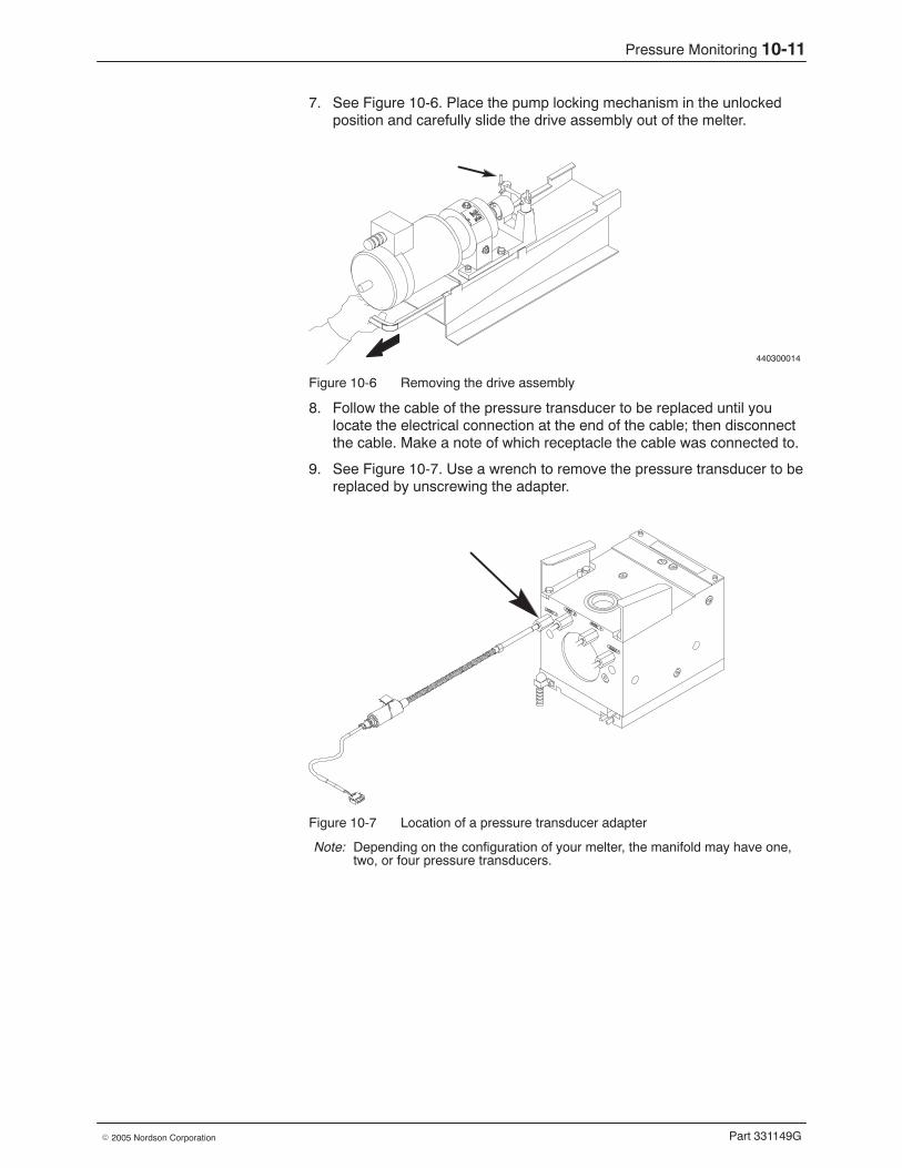
Pressure Monitoring 10-11
Part 331149G� 2005 Nordson Corporation
7. See Figure 10-6. Place the pump locking mechanism in the unlockedposition and carefully slide the drive assembly out of the melter.
440300014
Figure 10-6 Removing the drive assembly
8. Follow the cable of the pressure transducer to be replaced until youlocate the electrical connection at the end of the cable; then disconnectthe cable. Make a note of which receptacle the cable was connected to.
9. See Figure 10-7. Use a wrench to remove the pressure transducer to bereplaced by unscrewing the adapter.
Figure 10-7 Location of a pressure transducer adapter
Note: Depending on the configuration of your melter, the manifold may have one,two, or four pressure transducers.
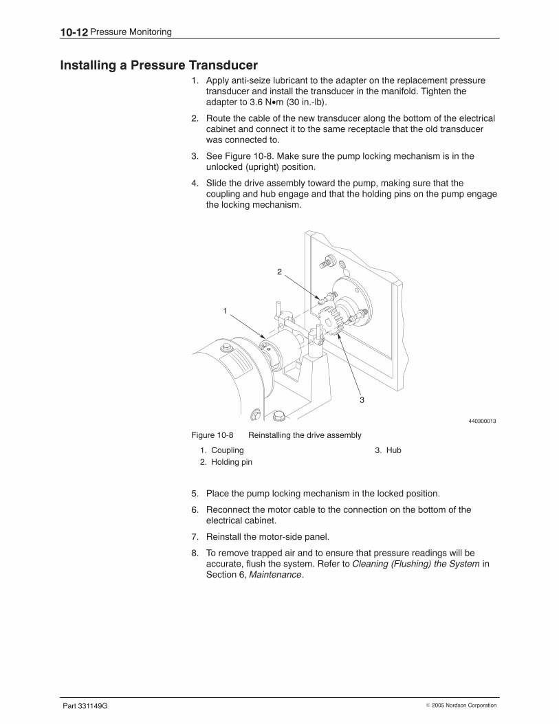
Pressure Monitoring10-12
Part 331149G � 2005 Nordson Corporation
Installing a Pressure Transducer 1. Apply anti-seize lubricant to the adapter on the replacement pressure
transducer and install the transducer in the manifold. Tighten theadapter to 3.6 N•m (30 in.-lb).
2. Route the cable of the new transducer along the bottom of the electricalcabinet and connect it to the same receptacle that the old transducerwas connected to.
3. See Figure 10-8. Make sure the pump locking mechanism is in theunlocked (upright) position.
4. Slide the drive assembly toward the pump, making sure that thecoupling and hub engage and that the holding pins on the pump engagethe locking mechanism.
440300013
1
2
3
Figure 10-8 Reinstalling the drive assembly
1. Coupling2. Holding pin
3. Hub
5. Place the pump locking mechanism in the locked position.
6. Reconnect the motor cable to the connection on the bottom of theelectrical cabinet.
7. Reinstall the motor-side panel.
8. To remove trapped air and to ensure that pressure readings will beaccurate, flush the system. Refer to Cleaning (Flushing) the System inSection 6, Maintenance.
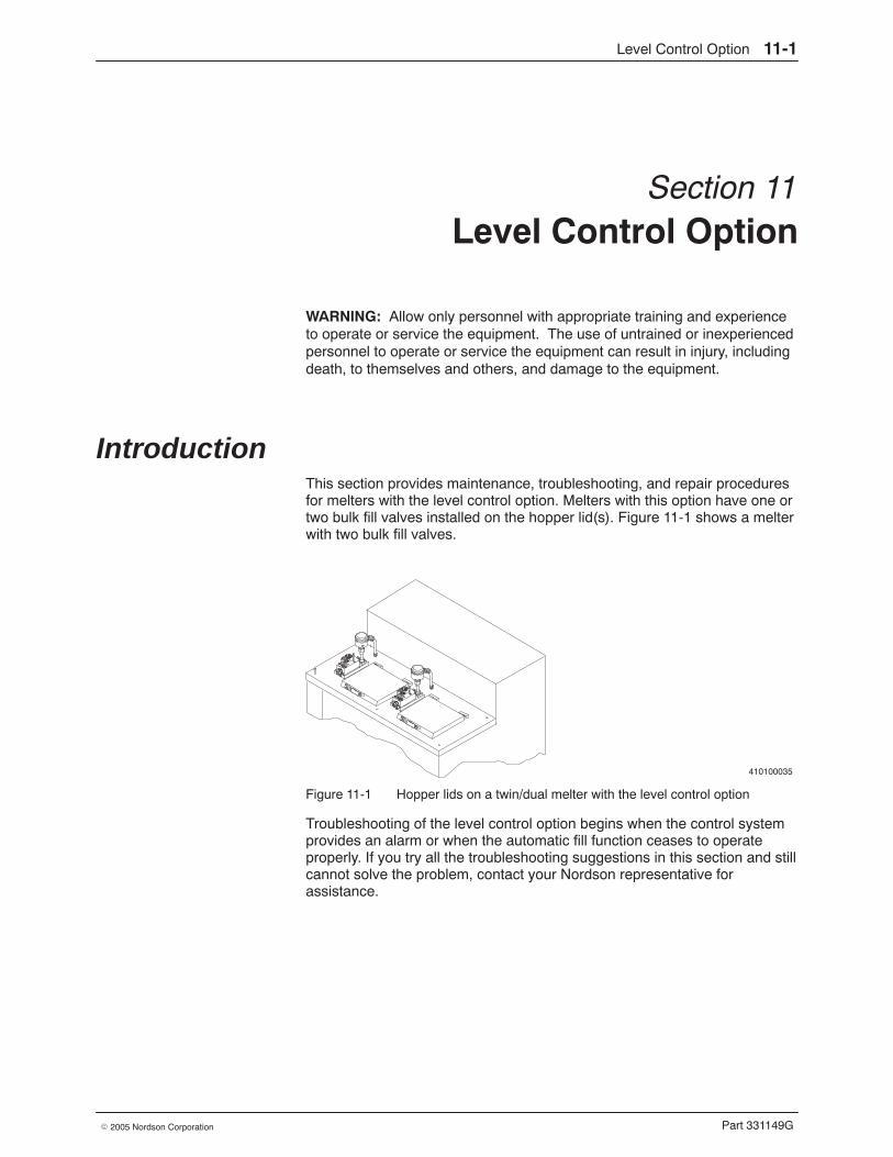
Level Control Option 11-1
Part 331149G� 2005 Nordson Corporation
Section 11Level Control Option
WARNING: Allow only personnel with appropriate training and experienceto operate or service the equipment. The use of untrained or inexperiencedpersonnel to operate or service the equipment can result in injury, includingdeath, to themselves and others, and damage to the equipment.
Introduction This section provides maintenance, troubleshooting, and repair proceduresfor melters with the level control option. Melters with this option have one ortwo bulk fill valves installed on the hopper lid(s). Figure 11-1 shows a melterwith two bulk fill valves.
410100035
Figure 11-1 Hopper lids on a twin/dual melter with the level control option
Troubleshooting of the level control option begins when the control systemprovides an alarm or when the automatic fill function ceases to operateproperly. If you try all the troubleshooting suggestions in this section and stillcannot solve the problem, contact your Nordson representative forassistance.
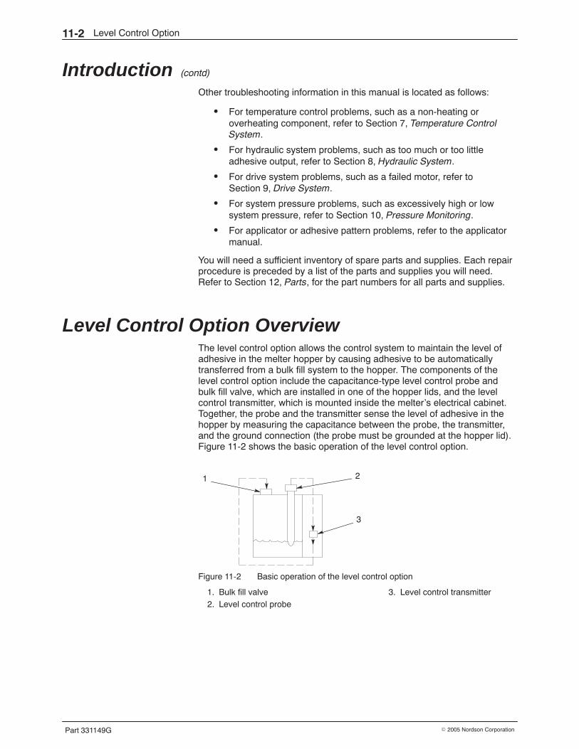
Level Control Option11-2
Part 331149G � 2005 Nordson Corporation
Introduction (contd)
Other troubleshooting information in this manual is located as follows:
� For temperature control problems, such as a non-heating oroverheating component, refer to Section 7, Temperature ControlSystem.
� For hydraulic system problems, such as too much or too littleadhesive output, refer to Section 8, Hydraulic System.
� For drive system problems, such as a failed motor, refer toSection 9, Drive System.
� For system pressure problems, such as excessively high or lowsystem pressure, refer to Section 10, Pressure Monitoring.
� For applicator or adhesive pattern problems, refer to the applicatormanual.
You will need a sufficient inventory of spare parts and supplies. Each repairprocedure is preceded by a list of the parts and supplies you will need.Refer to Section 12, Parts, for the part numbers for all parts and supplies.
Level Control Option Overview The level control option allows the control system to maintain the level ofadhesive in the melter hopper by causing adhesive to be automaticallytransferred from a bulk fill system to the hopper. The components of thelevel control option include the capacitance-type level control probe andbulk fill valve, which are installed in one of the hopper lids, and the levelcontrol transmitter, which is mounted inside the melter’s electrical cabinet.Together, the probe and the transmitter sense the level of adhesive in thehopper by measuring the capacitance between the probe, the transmitter,and the ground connection (the probe must be grounded at the hopper lid).Figure 11-2 shows the basic operation of the level control option.
1 2
3
Figure 11-2 Basic operation of the level control option
1. Bulk fill valve2. Level control probe
3. Level control transmitter
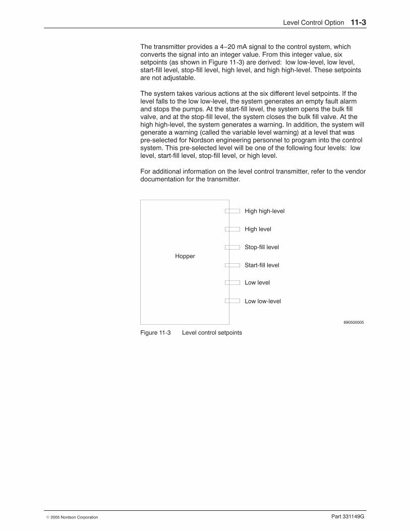
Level Control Option 11-3
Part 331149G� 2005 Nordson Corporation
The transmitter provides a 4−20 mA signal to the control system, whichconverts the signal into an integer value. From this integer value, sixsetpoints (as shown in Figure 11-3) are derived: low low-level, low level,start-fill level, stop-fill level, high level, and high high-level. These setpointsare not adjustable.
The system takes various actions at the six different level setpoints. If thelevel falls to the low low-level, the system generates an empty fault alarmand stops the pumps. At the start-fill level, the system opens the bulk fillvalve, and at the stop-fill level, the system closes the bulk fill valve. At thehigh high-level, the system generates a warning. In addition, the system willgenerate a warning (called the variable level warning) at a level that waspre-selected for Nordson engineering personnel to program into the controlsystem. This pre-selected level will be one of the following four levels: lowlevel, start-fill level, stop-fill level, or high level.
For additional information on the level control transmitter, refer to the vendordocumentation for the transmitter.
690500005
High high-level
High level
Stop-fill level
Start-fill level
Low level
Low low-level
Hopper
Figure 11-3 Level control setpoints
Level Control Option11-4
Part 331149G � 2005 Nordson Corporation
Troubleshooting Tables These troubleshooting tables describe the problems you may encounter andprovide corrective actions for handling those problems. When necessary,the tables refer to the troubleshooting procedures contained in theTroubleshooting Procedures part of this section.
Refer to the appropriate troubleshooting table for the type of problem youare experiencing:
� Alarm Messages� Level Control Problems
WARNING: Always wear heat-protective clothing, goggles (ANSI Z87.1 orequivalent), and safety gloves when working with hot melt equipment.
WARNING: Risk of equipment damage, personal injury, or death. Onlyqualifed personnel may perform electrical troubleshooting activities. Followelectrical safety procedures and observe all high-voltage indicators.
WARNING: Before performing any electrical or hydraulic troubleshootingactivity, disconnect and lock out electrical power as appropriate. Refer toRemoving Power in Section 6, Maintenance.
WARNING: Before performing any troubleshooting activity on hydrualicsystem components, relieve system pressure. Refer to Relieving SystemPressure in Section 6, Maintenance.
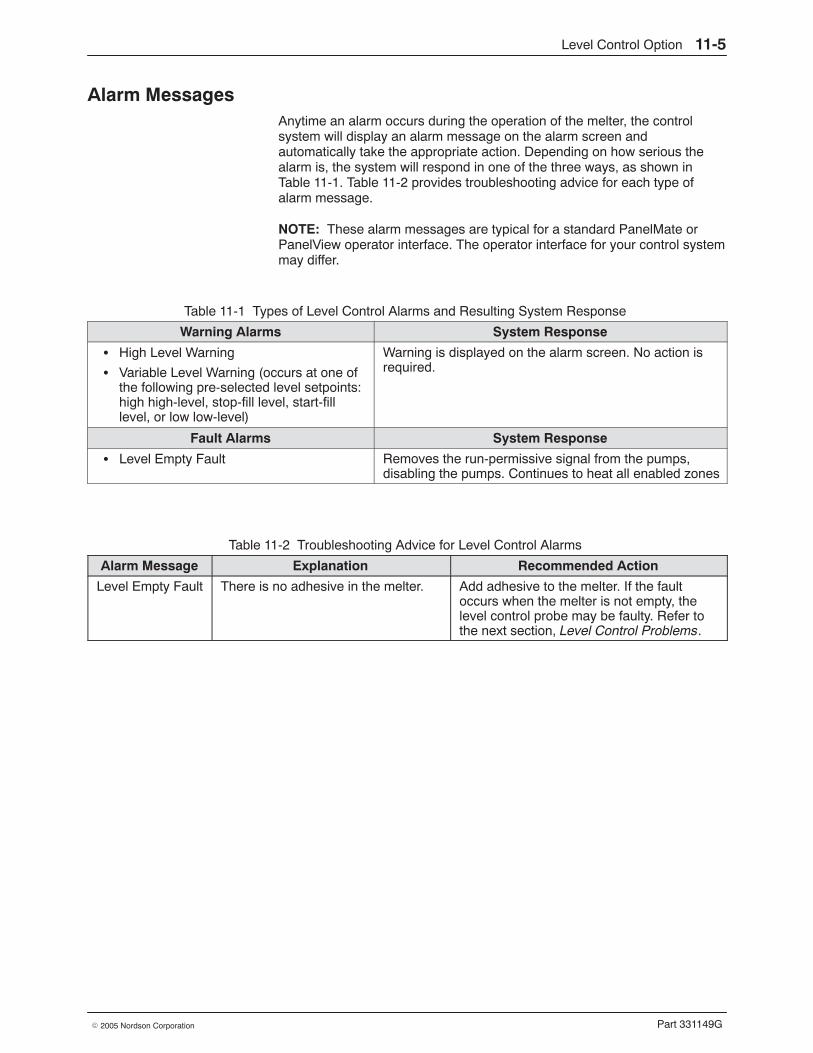
Level Control Option 11-5
Part 331149G� 2005 Nordson Corporation
Alarm Messages Anytime an alarm occurs during the operation of the melter, the controlsystem will display an alarm message on the alarm screen andautomatically take the appropriate action. Depending on how serious thealarm is, the system will respond in one of the three ways, as shown inTable 11-1. Table 11-2 provides troubleshooting advice for each type ofalarm message.
NOTE: These alarm messages are typical for a standard PanelMate orPanelView operator interface. The operator interface for your control systemmay differ.
Table 11-1 Types of Level Control Alarms and Resulting System Response
Warning Alarms System Response
� High Level Warning
� Variable Level Warning (occurs at one ofthe following pre-selected level setpoints:high high-level, stop-fill level, start-filllevel, or low low-level)
Warning is displayed on the alarm screen. No action isrequired.
Fault Alarms System Response
� Level Empty Fault Removes the run-permissive signal from the pumps,disabling the pumps. Continues to heat all enabled zones
Table 11-2 Troubleshooting Advice for Level Control Alarms
Alarm Message Explanation Recommended Action
Level Empty Fault There is no adhesive in the melter. Add adhesive to the melter. If the faultoccurs when the melter is not empty, thelevel control probe may be faulty. Refer tothe next section, Level Control Problems.
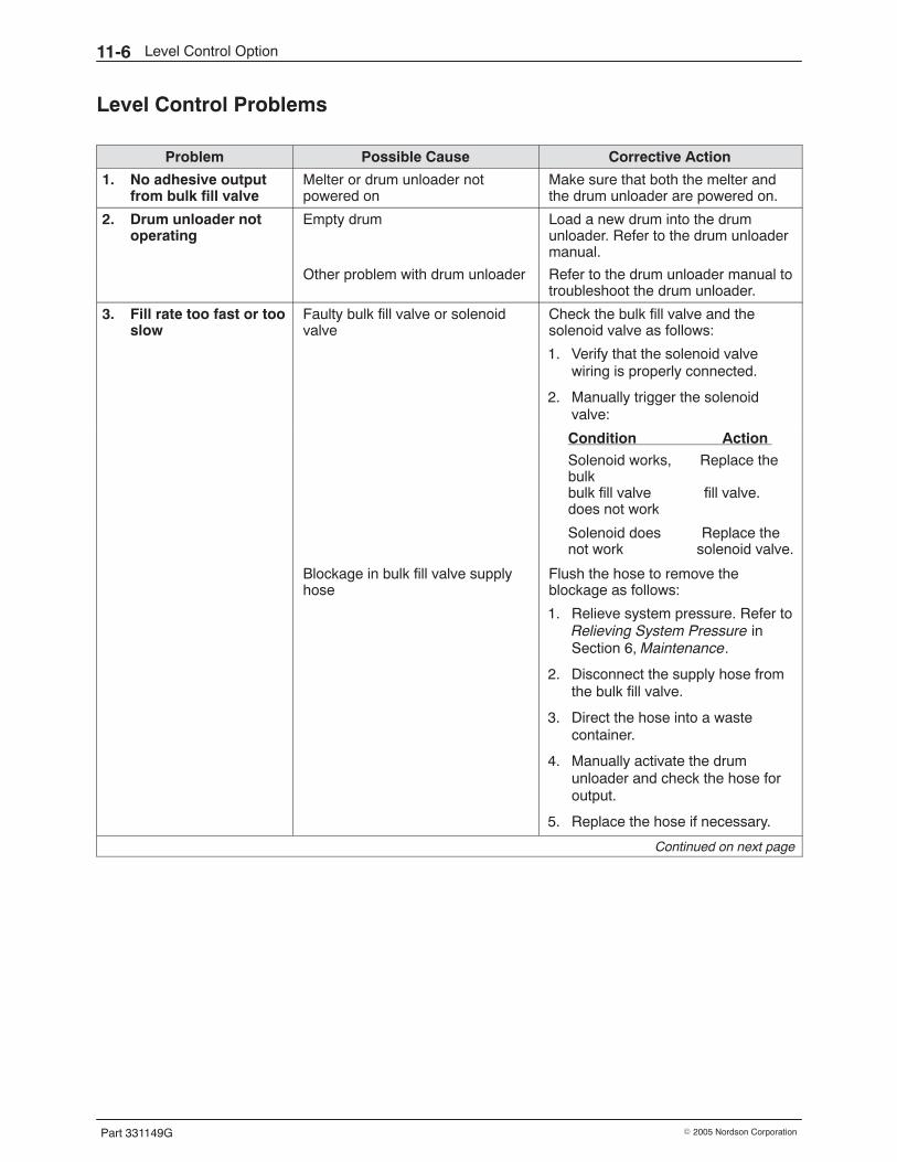
Level Control Option11-6
Part 331149G � 2005 Nordson Corporation
Level Control Problems
Problem Possible Cause Corrective Action
1. No adhesive outputfrom bulk fill valve
Melter or drum unloader notpowered on
Make sure that both the melter andthe drum unloader are powered on.
2. Drum unloader notoperating
Empty drum Load a new drum into the drumunloader. Refer to the drum unloadermanual.
Other problem with drum unloader Refer to the drum unloader manual totroubleshoot the drum unloader.
3. Fill rate too fast or tooslow
Faulty bulk fill valve or solenoidvalve
Check the bulk fill valve and thesolenoid valve as follows:
1. Verify that the solenoid valvewiring is properly connected.
2. Manually trigger the solenoidvalve:
Condition Action
Solenoid works, Replace thebulkbulk fill valve fill valve.does not work
Solenoid does Replace thenot work solenoid valve.
Blockage in bulk fill valve supplyhose
Flush the hose to remove theblockage as follows:
1. Relieve system pressure. Refer toRelieving System Pressure inSection 6, Maintenance.
2. Disconnect the supply hose fromthe bulk fill valve.
3. Direct the hose into a wastecontainer.
4. Manually activate the drumunloader and check the hose foroutput.
5. Replace the hose if necessary.
Continued on next page
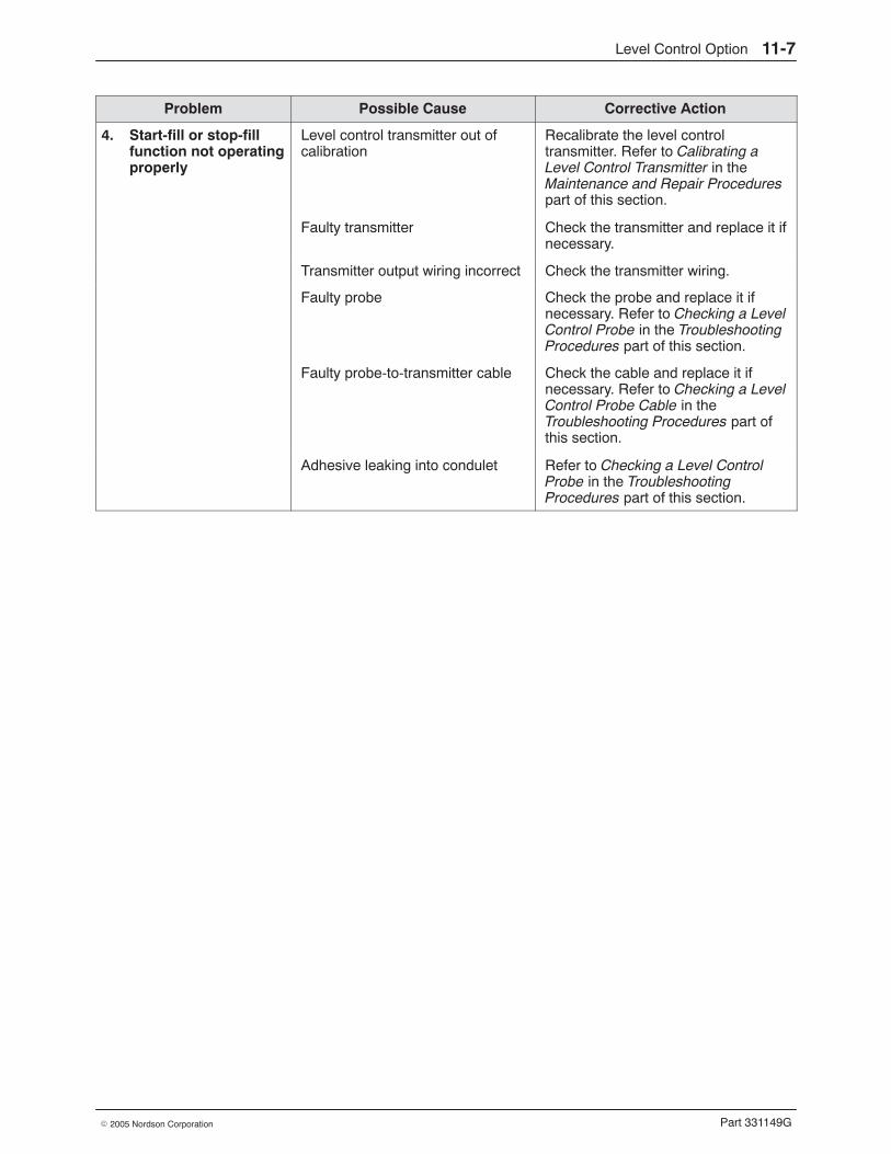
Level Control Option 11-7
Part 331149G� 2005 Nordson Corporation
Problem Possible Cause Corrective Action
4. Start-fill or stop-fillfunction not operatingproperly
Level control transmitter out ofcalibration
Recalibrate the level controltransmitter. Refer to Calibrating aLevel Control Transmitter in theMaintenance and Repair Procedurespart of this section.
Faulty transmitter Check the transmitter and replace it ifnecessary.
Transmitter output wiring incorrect Check the transmitter wiring.
Faulty probe Check the probe and replace it ifnecessary. Refer to Checking a LevelControl Probe in the TroubleshootingProcedures part of this section.
Faulty probe-to-transmitter cable Check the cable and replace it ifnecessary. Refer to Checking a LevelControl Probe Cable in theTroubleshooting Procedures part ofthis section.
Adhesive leaking into condulet Refer to Checking a Level ControlProbe in the TroubleshootingProcedures part of this section.
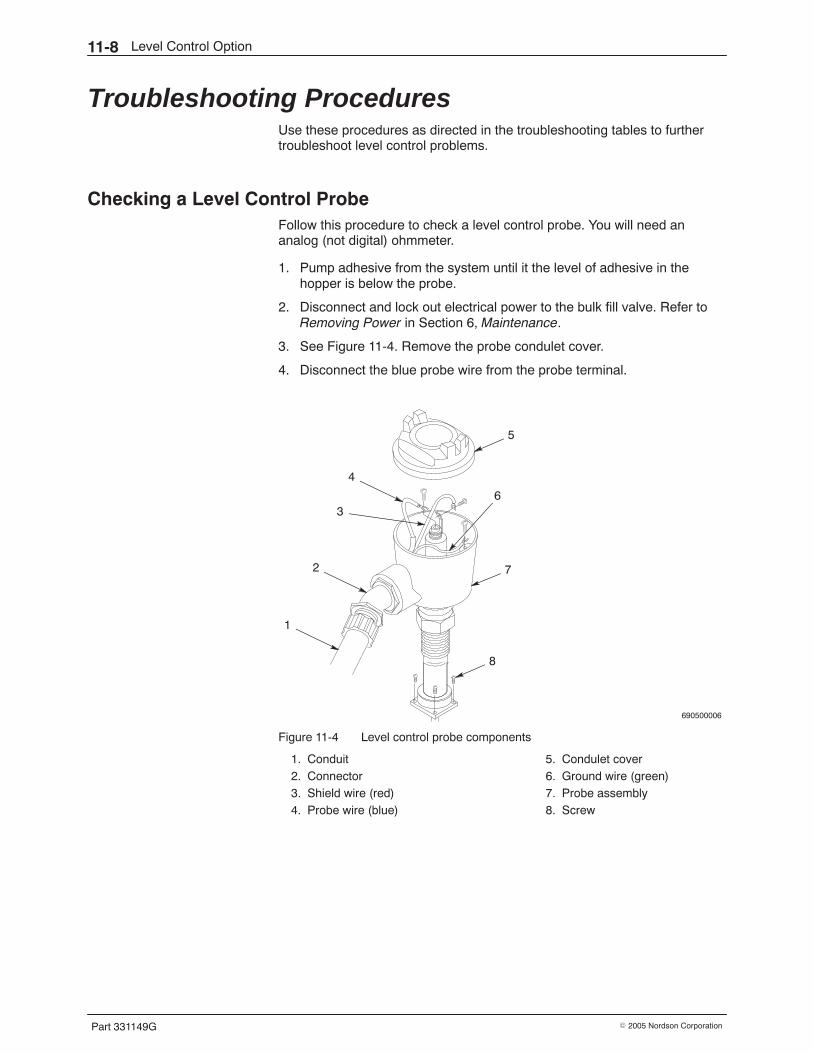
Level Control Option11-8
Part 331149G � 2005 Nordson Corporation
Troubleshooting Procedures Use these procedures as directed in the troubleshooting tables to furthertroubleshoot level control problems.
Checking a Level Control Probe Follow this procedure to check a level control probe. You will need ananalog (not digital) ohmmeter.
1. Pump adhesive from the system until it the level of adhesive in thehopper is below the probe.
2. Disconnect and lock out electrical power to the bulk fill valve. Refer toRemoving Power in Section 6, Maintenance.
3. See Figure 11-4. Remove the probe condulet cover.
4. Disconnect the blue probe wire from the probe terminal.
690500006
5
2 7
8
6
1
4
3
Figure 11-4 Level control probe components
1. Conduit2. Connector3. Shield wire (red)4. Probe wire (blue)
5. Condulet cover6. Ground wire (green)7. Probe assembly8. Screw
Level Control Option 11-9
Part 331149G� 2005 Nordson Corporation
5. Use an analog (not digital) ohmmeter to check the resistance betweenthe probe terminal and the ground wire:
Resistance Indication Action
Infinite Normal Go to step 6.
Less than 1 MΩ(hopper empty)
Defects are present in theprobe insulation.
Adhesive may be leakingthrough the probe mountingblock into the condulet.
The probe may bedefective.
Replace the probe.
6. Add adhesive to the hopper until the adhesive level is between thestart-fill and stop-fill points.
7. Use an analog ohmmeter to check the resistance as shown in thefollowing table.
Measurement Location Resistance Indication Action
Between probe terminaland ground wire
Infinite Normal Return to theappropriatetroubleshooting table.
Less than 1 MΩ (normallevel in hopper)
Defects are present inthe probe insulation,adhesive may beleaking into thecondulet, or the probemay be defective.
Replace the probe.
Between probe wire andshield wire
Infinite Normal Return to theappropriatetroubleshooting table.
Less than 1 MΩ (normallevel in hopper)
Defects are present inthe probe insulation,adhesive may beleaking into thecondulet, or the probemay be defective.
Replace the probe.
Between shield wire andground wire
Infinite Normal Return to theappropriatetroubleshooting table.
Less than 1 MΩ (normallevel in hopper)
Condensation may bepresent in the condulet,adhesive may beleaking into thecondulet, or the probemay be defective.
Replace the probe.
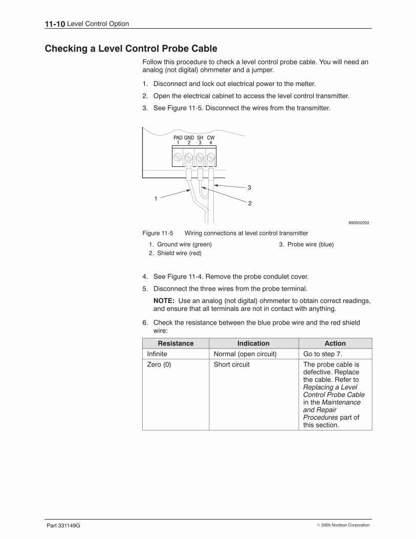
Level Control Option11-10
Part 331149G � 2005 Nordson Corporation
Checking a Level Control Probe Cable Follow this procedure to check a level control probe cable. You will need ananalog (not digital) ohmmeter and a jumper.
1. Disconnect and lock out electrical power to the melter.
2. Open the electrical cabinet to access the level control transmitter.
3. See Figure 11-5. Disconnect the wires from the transmitter.
690502002
PAD1
GND2
SH3
CW4
12
3
Figure 11-5 Wiring connections at level control transmitter
1. Ground wire (green)2. Shield wire (red)
3. Probe wire (blue)
4. See Figure 11-4. Remove the probe condulet cover.
5. Disconnect the three wires from the probe terminal.
NOTE: Use an analog (not digital) ohmmeter to obtain correct readings,and ensure that all terminals are not in contact with anything.
6. Check the resistance between the blue probe wire and the red shieldwire:
Resistance Indication Action
Infinite Normal (open circuit) Go to step 7.
Zero (0) Short circuit The probe cable isdefective. Replacethe cable. Refer toReplacing a LevelControl Probe Cablein the Maintenanceand RepairProcedures part ofthis section.
Level Control Option 11-11
Part 331149G� 2005 Nordson Corporation
7. Connect a jumper between the blue probe wire and the green groundwire at one end of the cable; then check the resistance between the blueprobe wire and the green ground wire at the other end of the cable:
Resistance Indication Action
Zero (0) Normal(short circuit)
Go to step 8.
Infinite Open circuit The probe cable isdefective. Replace thecable. Refer to Replacing aLevel Control Probe Cablein the Maintenance andRepair Procedures part ofthis section.
8. Remove the jumper installed in step 7. Check the resistance betweenthe green ground wire and the red shield wire:
Resistance Indication Action
Infinite Normal(open circuit)
The probe cable is notdefective. Restore thesystem to normal operation.
Zero (0) Short circuit The probe cable isdefective. Replace thecable. Refer to Replacing aLevel Control Probe Cablein the Maintenance andRepair Procedures part ofthis section.
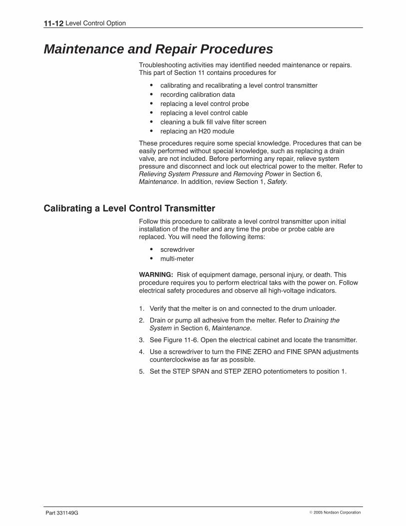
Level Control Option11-12
Part 331149G � 2005 Nordson Corporation
Maintenance and Repair Procedures Troubleshooting activities may identified needed maintenance or repairs.This part of Section 11 contains procedures for
� calibrating and recalibrating a level control transmitter� recording calibration data� replacing a level control probe� replacing a level control cable� cleaning a bulk fill valve filter screen� replacing an H20 module
These procedures require some special knowledge. Procedures that can beeasily performed without special knowledge, such as replacing a drainvalve, are not included. Before performing any repair, relieve systempressure and disconnect and lock out electrical power to the melter. Refer toRelieving System Pressure and Removing Power in Section 6,Maintenance. In addition, review Section 1, Safety.
Calibrating a Level Control Transmitter Follow this procedure to calibrate a level control transmitter upon initialinstallation of the melter and any time the probe or probe cable arereplaced. You will need the following items:
� screwdriver� multi-meter
WARNING: Risk of equipment damage, personal injury, or death. Thisprocedure requires you to perform electrical taks with the power on. Followelectrical safety procedures and observe all high-voltage indicators.
1. Verify that the melter is on and connected to the drum unloader.
2. Drain or pump all adhesive from the melter. Refer to Draining theSystem in Section 6, Maintenance.
3. See Figure 11-6. Open the electrical cabinet and locate the transmitter.
4. Use a screwdriver to turn the FINE ZERO and FINE SPAN adjustmentscounterclockwise as far as possible.
5. Set the STEP SPAN and STEP ZERO potentiometers to position 1.
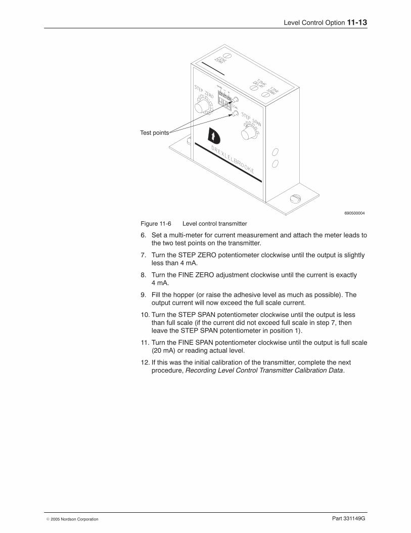
Level Control Option 11-13
Part 331149G� 2005 Nordson Corporation
690500004
Test points
Figure 11-6 Level control transmitter
6. Set a multi-meter for current measurement and attach the meter leads tothe two test points on the transmitter.
7. Turn the STEP ZERO potentiometer clockwise until the output is slightlyless than 4 mA.
8. Turn the FINE ZERO adjustment clockwise until the current is exactly4 mA.
9. Fill the hopper (or raise the adhesive level as much as possible). Theoutput current will now exceed the full scale current.
10. Turn the STEP SPAN potentiometer clockwise until the output is lessthan full scale (if the current did not exceed full scale in step 7, thenleave the STEP SPAN potentiometer in position 1).
11. Turn the FINE SPAN potentiometer clockwise until the output is full scale(20 mA) or reading actual level.
12. If this was the initial calibration of the transmitter, complete the nextprocedure, Recording Level Control Transmitter Calibration Data.
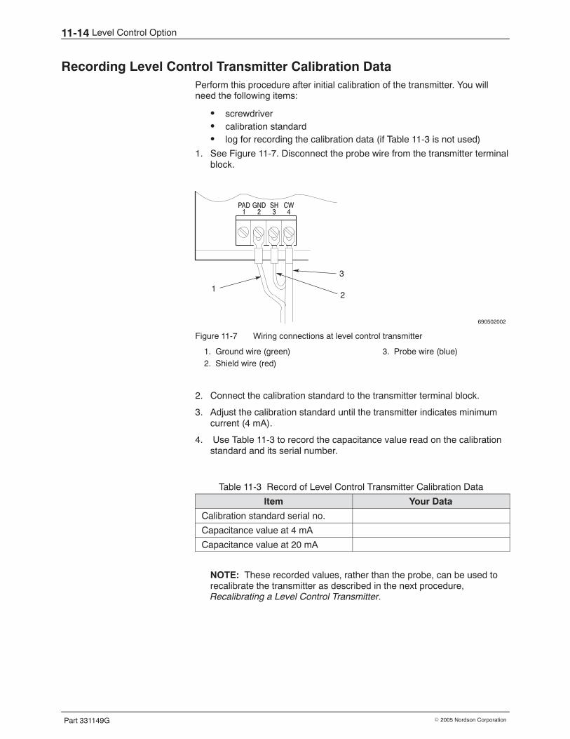
Level Control Option11-14
Part 331149G � 2005 Nordson Corporation
Recording Level Control Transmitter Calibration Data Perform this procedure after initial calibration of the transmitter. You willneed the following items:
� screwdriver� calibration standard� log for recording the calibration data (if Table 11-3 is not used)
1. See Figure 11-7. Disconnect the probe wire from the transmitter terminalblock.
690502002
PAD1
GND2
SH3
CW4
12
3
Figure 11-7 Wiring connections at level control transmitter
1. Ground wire (green)2. Shield wire (red)
3. Probe wire (blue)
2. Connect the calibration standard to the transmitter terminal block.
3. Adjust the calibration standard until the transmitter indicates minimumcurrent (4 mA).
4. Use Table 11-3 to record the capacitance value read on the calibrationstandard and its serial number.
Table 11-3 Record of Level Control Transmitter Calibration Data
Item Your Data
Calibration standard serial no.
Capacitance value at 4 mA
Capacitance value at 20 mA
NOTE: These recorded values, rather than the probe, can be used torecalibrate the transmitter as described in the next procedure,Recalibrating a Level Control Transmitter.
Level Control Option 11-15
Part 331149G� 2005 Nordson Corporation
5. Adjust the calibration standard until the transmitter indicates maximumcurrent (20 mA).
6. Use Table 11-3 to record the capacitance value read on the calibrationstandard.
7. Disconnect the calibration standard from the transmitter terminals andreconnect the probe wires.
Level Control Option11-16
Part 331149G � 2005 Nordson Corporation
Recalibrating a Level Control Transmitter Follow this procedure to recalibrate a transmitter if you suspect that thecalibration is off or if you replace the transmitter. You will need the followingitems:
� screwdriver� calibration standard� log of recorded calibration data (from Table 11-3 if applicable)
1. See Figure 11-8. Disconnect the probe wire from the transmitterterminals.
690502002
PAD1
GND2
SH3
CW4
12
3
Figure 11-8 Wiring connections at level control transmitter
1. Ground wire (green)2. Shield wire (red)
3. Probe wire (blue)
2. Connect the calibration standard to the transmitter terminals.
3. Set the calibration standard to the values recorded in the precedingprocedure, Recording Level Control Calibration Data.
4. See Figure 11-6. If necessary, adjust the FINE ZERO potentiometer forthe minimum current calibration and the FINE SPAN potentiometer forthe maximum current calibration.
5. Disconnect the calibration standard from transmitter terminals andreconnect the probe wires.
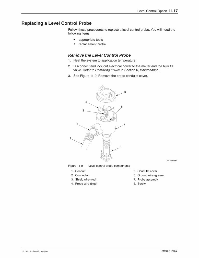
Level Control Option 11-17
Part 331149G� 2005 Nordson Corporation
Replacing a Level Control Probe Follow these procedures to replace a level control probe. You will need thefollowing items:
� appropriate tools� replacement probe
Remove the Level Control Probe 1. Heat the system to application temperature.
2. Disconnect and lock out electrical power to the melter and the bulk fillvalve. Refer to Removing Power in Section 6, Maintenance.
3. See Figure 11-9. Remove the probe condulet cover.
690500006
5
2 7
8
6
1
4
3
Figure 11-9 Level control probe components
1. Conduit2. Connector3. Shield wire (red)4. Probe wire (blue)
5. Condulet cover6. Ground wire (green)7. Probe assembly8. Screw

Level Control Option11-18
Part 331149G � 2005 Nordson Corporation
Replacing a Level Control Probe (contd)
4. Disconnect the wires.
5. Disconnect the conduit from the connector and pull the conduit andwires from the probe housing.
6. Remove the screws that secure the probe assembly to the hopper lidand pull the assembly straight up and out of the hopper.
Install the Level Control Probe 1. Mount the new probe assembly on the lid with the four screws removed
previously.
2. Route the probe wires through the connector and probe housing to thecolor-coded terminals.
NOTE: Make sure the probe is well grounded to ensure properoperation.
3. Connect the conduit to the connector.
4. Connect the color-coded wires to the matching terminals.
5. Reinstall the condulet cover and restore the system to normal operation.
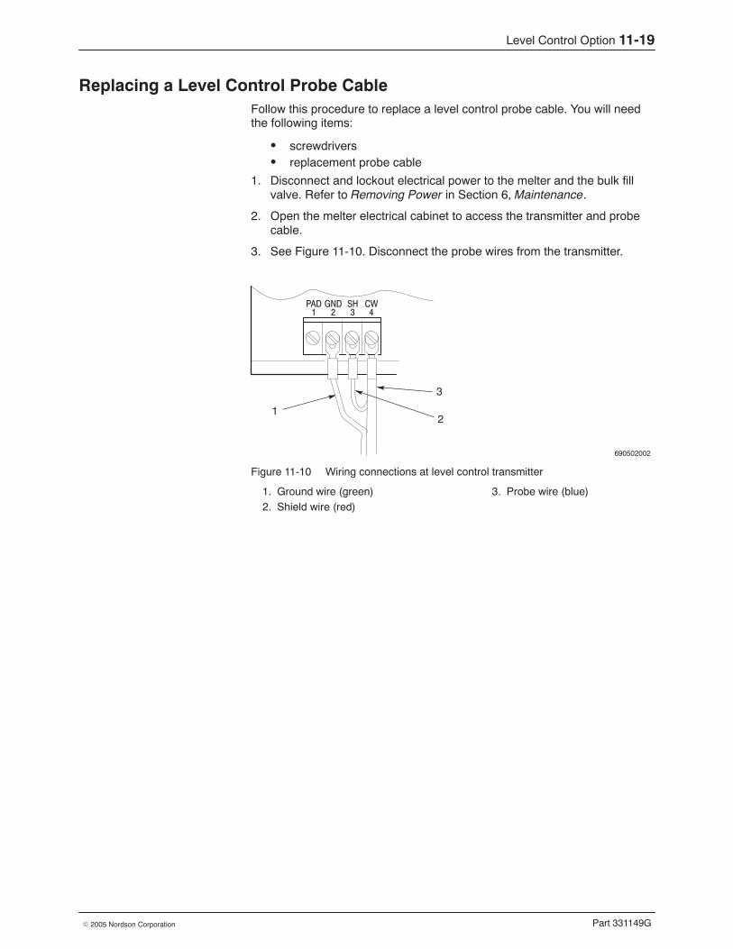
Level Control Option 11-19
Part 331149G� 2005 Nordson Corporation
Replacing a Level Control Probe Cable Follow this procedure to replace a level control probe cable. You will needthe following items:
� screwdrivers� replacement probe cable
1. Disconnect and lockout electrical power to the melter and the bulk fillvalve. Refer to Removing Power in Section 6, Maintenance.
2. Open the melter electrical cabinet to access the transmitter and probecable.
3. See Figure 11-10. Disconnect the probe wires from the transmitter.
690502002
PAD1
GND2
SH3
CW4
12
3
Figure 11-10 Wiring connections at level control transmitter
1. Ground wire (green)2. Shield wire (red)
3. Probe wire (blue)

Level Control Option11-20
Part 331149G � 2005 Nordson Corporation
Replacing a Level Control Probe Cable (contd)
4. See Figure 11-11. Remove the condulet cover from the probe anddisconnect all three wires from the probe terminal.
690500006
5
2 7
8
6
1
4
3
Figure 11-11 Level control probe components
1. Conduit2. Connector3. Shield wire (red)4. Probe wire (blue)
5. Condulet cover6. Ground wire (green)7. Probe assembly8. Screw
5. Pull the cable out of the condulet.
6. Thread a new cable through the connector and condulet.
7. Connect the new cable wires to the color-coded probe terminals.
8. Reinstall the condulet cover.
9. Connect the new cable wires to the transmitter.
10. Calibrate the transmitter before restoring the system to normaloperation. Go to Calibrating a Level Control Transmitter earlier in thissection.
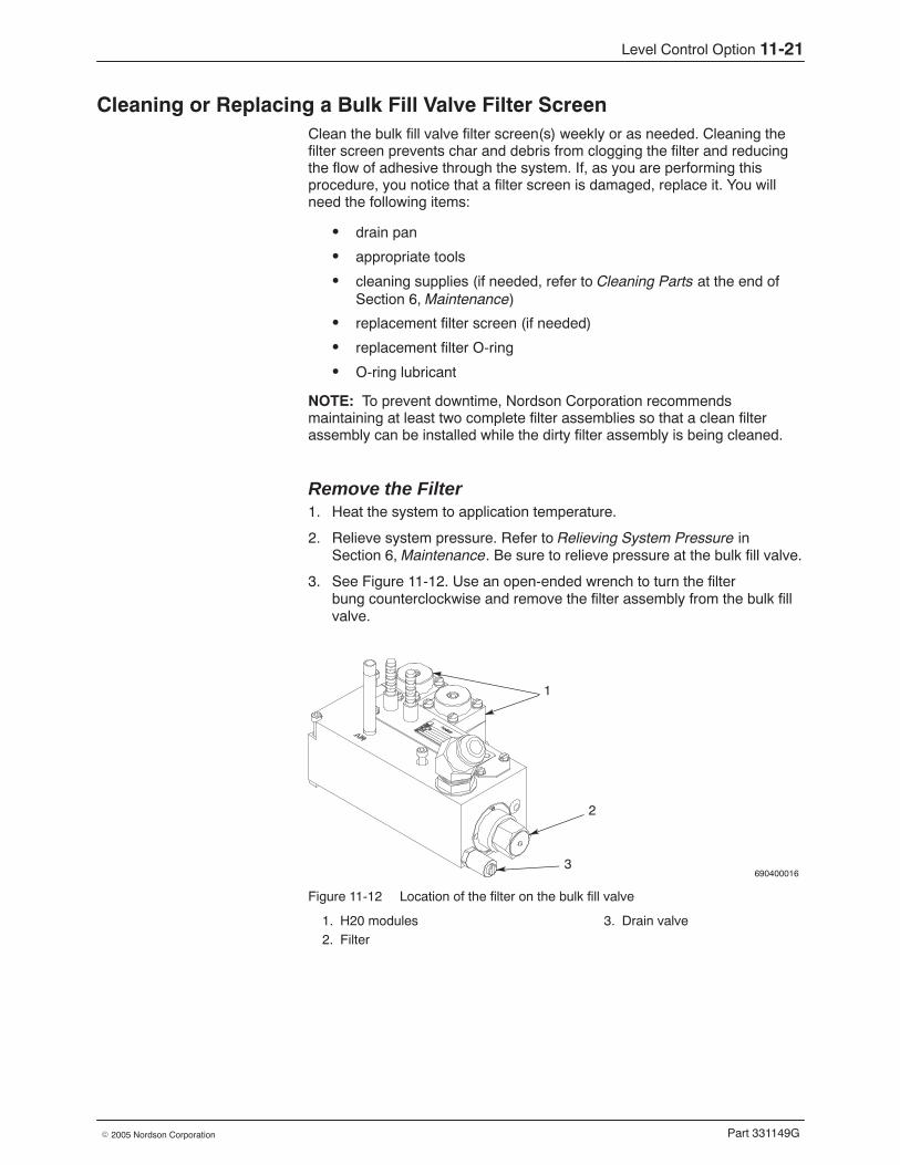
Level Control Option 11-21
Part 331149G� 2005 Nordson Corporation
Cleaning or Replacing a Bulk Fill Valve Filter Screen Clean the bulk fill valve filter screen(s) weekly or as needed. Cleaning thefilter screen prevents char and debris from clogging the filter and reducingthe flow of adhesive through the system. If, as you are performing thisprocedure, you notice that a filter screen is damaged, replace it. You willneed the following items:
� drain pan
� appropriate tools
� cleaning supplies (if needed, refer to Cleaning Parts at the end ofSection 6, Maintenance)
� replacement filter screen (if needed)
� replacement filter O-ring
� O-ring lubricant
NOTE: To prevent downtime, Nordson Corporation recommendsmaintaining at least two complete filter assemblies so that a clean filterassembly can be installed while the dirty filter assembly is being cleaned.
Remove the Filter 1. Heat the system to application temperature.
2. Relieve system pressure. Refer to Relieving System Pressure inSection 6, Maintenance. Be sure to relieve pressure at the bulk fill valve.
3. See Figure 11-12. Use an open-ended wrench to turn the filterbung counterclockwise and remove the filter assembly from the bulk fillvalve.
690400016
1
2
3
Figure 11-12 Location of the filter on the bulk fill valve
1. H20 modules2. Filter
3. Drain valve
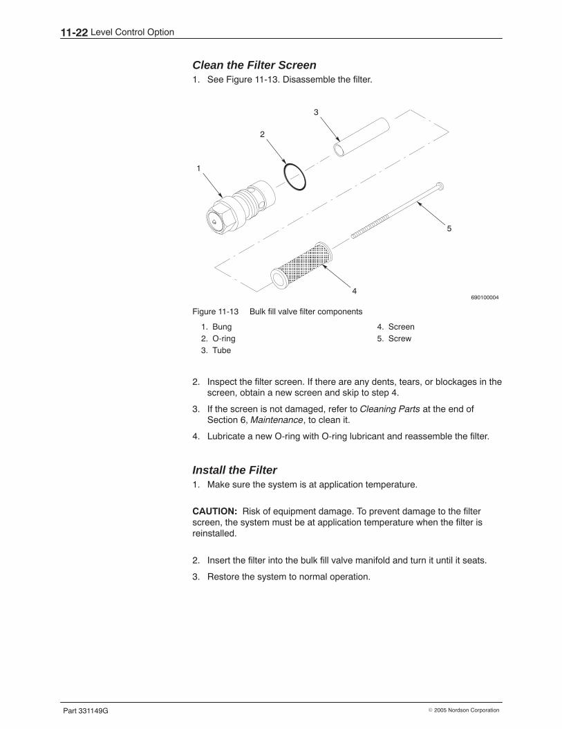
Level Control Option11-22
Part 331149G � 2005 Nordson Corporation
Clean the Filter Screen 1. See Figure 11-13. Disassemble the filter.
690100004
ÏÏÏÏÏÏÏÏÏÏÏÏÏÏÏÏÏÏÏÏ
3
2
1
5
4
Figure 11-13 Bulk fill valve filter components
1. Bung2. O-ring3. Tube
4. Screen5. Screw
2. Inspect the filter screen. If there are any dents, tears, or blockages in thescreen, obtain a new screen and skip to step 4.
3. If the screen is not damaged, refer to Cleaning Parts at the end ofSection 6, Maintenance, to clean it.
4. Lubricate a new O-ring with O-ring lubricant and reassemble the filter.
Install the Filter 1. Make sure the system is at application temperature.
CAUTION: Risk of equipment damage. To prevent damage to the filterscreen, the system must be at application temperature when the filter isreinstalled.
2. Insert the filter into the bulk fill valve manifold and turn it until it seats.
3. Restore the system to normal operation.
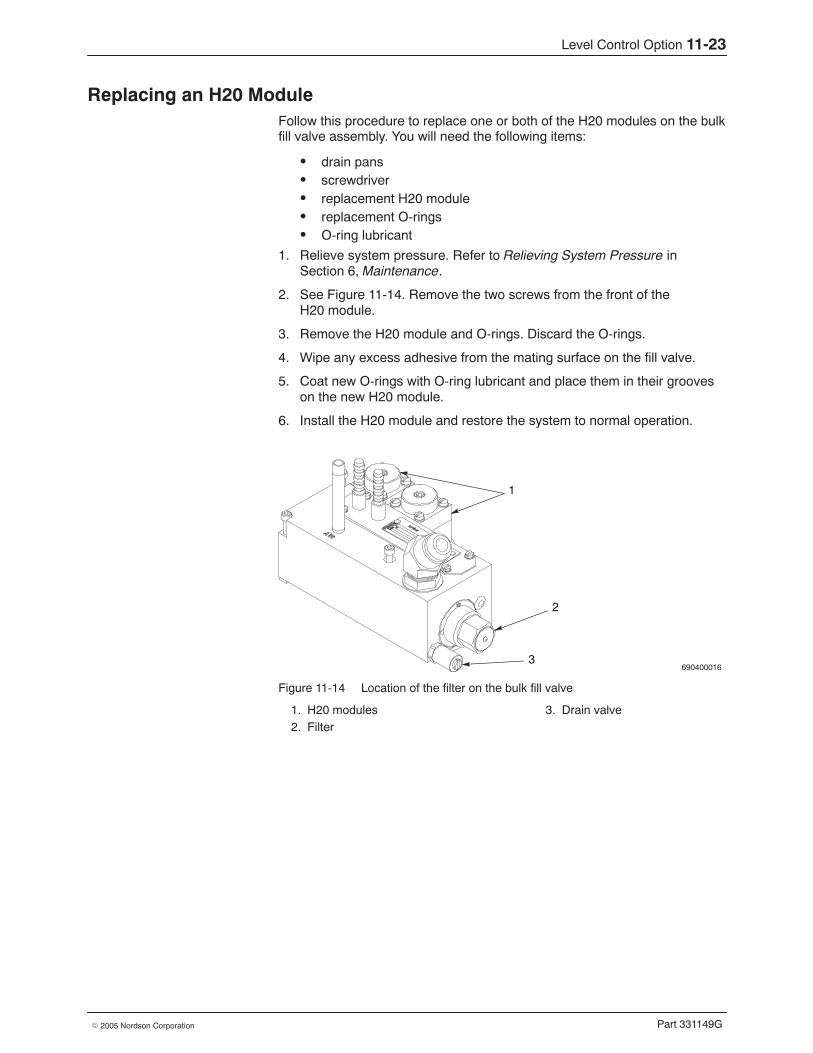
Level Control Option 11-23
Part 331149G� 2005 Nordson Corporation
Replacing an H20 Module Follow this procedure to replace one or both of the H20 modules on the bulkfill valve assembly. You will need the following items:
� drain pans� screwdriver� replacement H20 module� replacement O-rings� O-ring lubricant
1. Relieve system pressure. Refer to Relieving System Pressure inSection 6, Maintenance.
2. See Figure 11-14. Remove the two screws from the front of theH20 module.
3. Remove the H20 module and O-rings. Discard the O-rings.
4. Wipe any excess adhesive from the mating surface on the fill valve.
5. Coat new O-rings with O-ring lubricant and place them in their grooveson the new H20 module.
6. Install the H20 module and restore the system to normal operation.
690400016
1
2
3
Figure 11-14 Location of the filter on the bulk fill valve
1. H20 modules2. Filter
3. Drain valve

Level Control Option11-24
Part 331149G � 2005 Nordson Corporation
Parts 12-1
Part 331149G� 2005 Nordson Corporation
Section 12Parts
Using the Illustrated Parts Lists To order parts, call the Nordson Customer Service Center or your localNordson representative. Use these five-column parts lists, and theaccompanying illustrations, to describe and locate parts correctly. Thefollowing chart provides guidance for reading the parts lists.
The number in the Item column corresponds to the circled item number in theparts list illustration. A dash in this column indicates that the item is anassembly.
The number in the Part column is the Nordson part number you canuse to order the part. A series of dashes indicates that the part isnot saleable. In this case, you must order either the assembly inwhich the part is used or a service kit that includes the part.
The Description column describes the part and sometimesincludes dimensions or specifications.
The Note column contains letters that refer to notes at thebottom of the parts list. These notes provide importantinformation about the part.
The Quantity column tells you how many of the part isused to manufacture the assembly shown in the partslist illustration. A dash or AR in this column indicatesthat the amount of the item required in the assembly isnot quantifiable.
Item Part Description Quantity Note— 0000000 Assembly A —1 000000 � Part of assembly A 2 A2 - - - - - - � � Part of item 1 13 0000000 � � � Part of item 2 AR
NS 000000 � � � � Part of item 3 2NOTE A: Important information about item 1
AR: As Required
NS: Not Shown

Parts12-2
Part 331149G � 2005 Nordson Corporation
This page intentionally left blank.
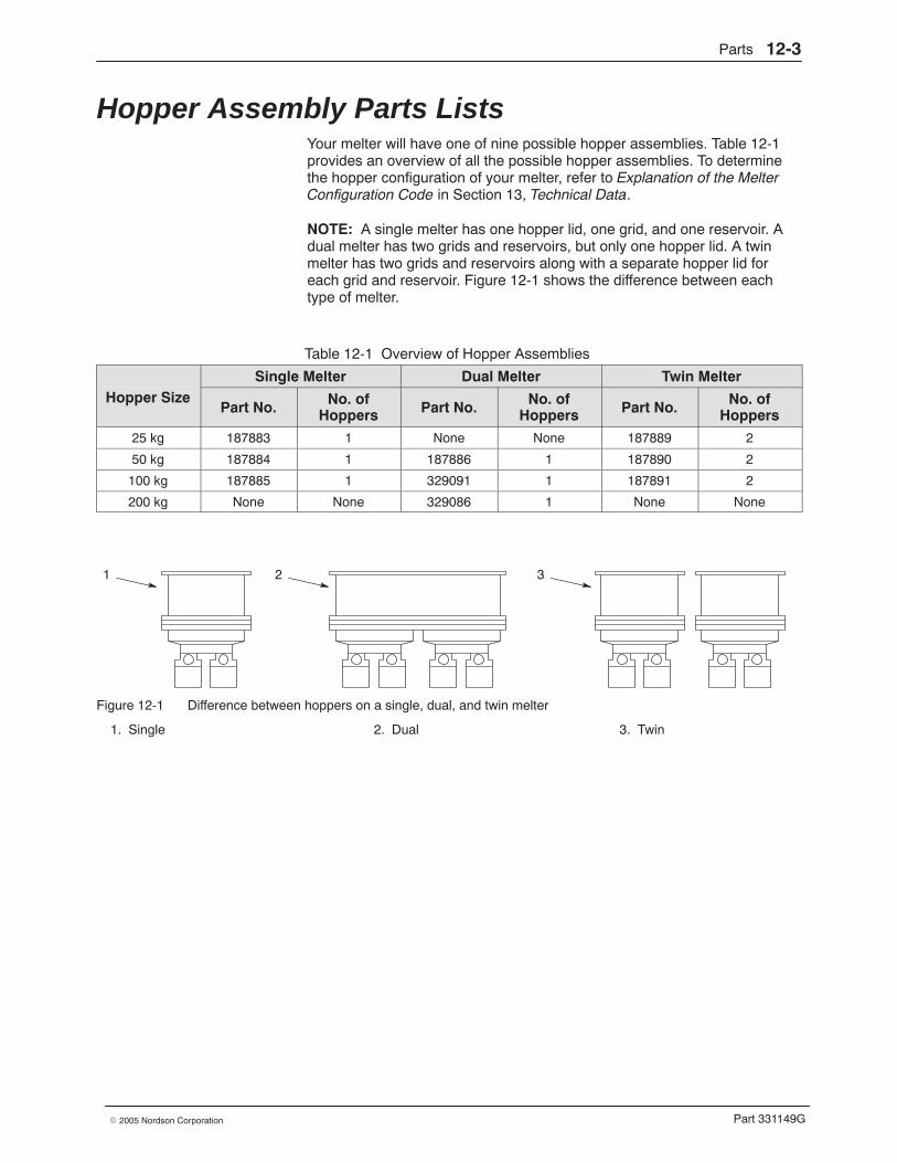
Parts 12-3
Part 331149G� 2005 Nordson Corporation
Hopper Assembly Parts Lists Your melter will have one of nine possible hopper assemblies. Table 12-1provides an overview of all the possible hopper assemblies. To determinethe hopper configuration of your melter, refer to Explanation of the MelterConfiguration Code in Section 13, Technical Data.
NOTE: A single melter has one hopper lid, one grid, and one reservoir. Adual melter has two grids and reservoirs, but only one hopper lid. A twinmelter has two grids and reservoirs along with a separate hopper lid foreach grid and reservoir. Figure 12-1 shows the difference between eachtype of melter.
Table 12-1 Overview of Hopper Assemblies
Single Melter Dual Melter Twin MelterHopper Size
Part No. No. ofHoppers Part No. No. of
Hoppers Part No. No. ofHoppers
25 kg 187883 1 None None 187889 2
50 kg 187884 1 187886 1 187890 2
100 kg 187885 1 329091 1 187891 2
200 kg None None 329086 1 None None
1 2 3
Figure 12-1 Difference between hoppers on a single, dual, and twin melter
1. Single 2. Dual 3. Twin
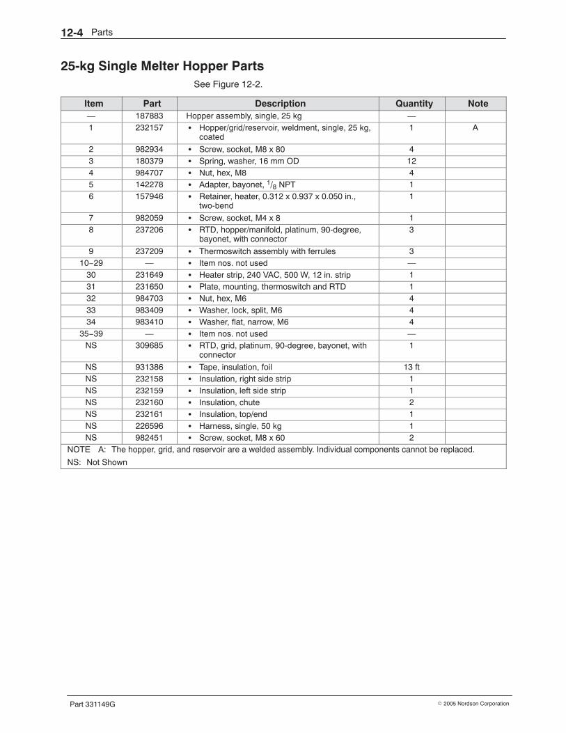
Parts12-4
Part 331149G � 2005 Nordson Corporation
25-kg Single Melter Hopper Parts See Figure 12-2.
Item Part Description Quantity Note— 187883 Hopper assembly, single, 25 kg —1 232157 � Hopper/grid/reservoir, weldment, single, 25 kg,
coated1 A
2 982934 � Screw, socket, M8 x 80 43 180379 � Spring, washer, 16 mm OD 124 984707 � Nut, hex, M8 45 142278 � Adapter, bayonet, 1/8 NPT 16 157946 � Retainer, heater, 0.312 x 0.937 x 0.050 in.,
two-bend1
7 982059 � Screw, socket, M4 x 8 18 237206 � RTD, hopper/manifold, platinum, 90-degree,
bayonet, with connector3
9 237209 � Thermoswitch assembly with ferrules 310−29 — � Item nos. not used —
30 231649 � Heater strip, 240 VAC, 500 W, 12 in. strip 131 231650 � Plate, mounting, thermoswitch and RTD 132 984703 � Nut, hex, M6 433 983409 � Washer, lock, split, M6 434 983410 � Washer, flat, narrow, M6 4
35−39 — � Item nos. not used —NS 309685 � RTD, grid, platinum, 90-degree, bayonet, with
connector1
NS 931386 � Tape, insulation, foil 13 ftNS 232158 � Insulation, right side strip 1NS 232159 � Insulation, left side strip 1NS 232160 � Insulation, chute 2NS 232161 � Insulation, top/end 1NS 226596 � Harness, single, 50 kg 1NS 982451 � Screw, socket, M8 x 60 2
NOTE A: The hopper, grid, and reservoir are a welded assembly. Individual components cannot be replaced.
NS: Not Shown
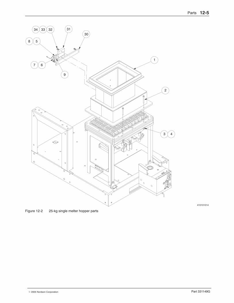
Parts 12-5
Part 331149G� 2005 Nordson Corporation
410101014
1
2
3 4
31
5
3230
9
67
8
3334
Figure 12-2 25-kg single melter hopper parts
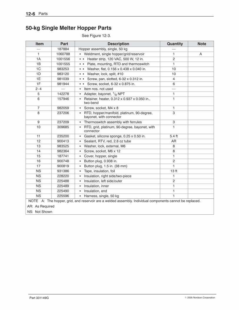
Parts12-6
Part 331149G � 2005 Nordson Corporation
50-kg Single Melter Hopper Parts See Figure 12-3.
Item Part Description Quantity Note— 187884 Hopper assembly, single, 50 kg —1 1060788 � Weldment, single hopper/grid/reservoir 1 A
1A 1001556 � � Heater strip, 120 VAC, 500 W, 12 in. 21B 1001555 � � Plate, mounting, RTD and thermoswitch 11C 983253 � � Washer, flat, 0.156 x 0.438 x 0.040 in. 101D 983120 � � Washer, lock, split, #10 101E 981039 � � Screw, pan, slotted, 6-32 x 0.312 in. 41F 981944 � � Screw, socket, 6-32 x 0.875 in. 62−4 — � Item nos. not used —5 142278 � Adapter, bayonet, 1/8 NPT 16 157946 � Retainer, heater, 0.312 x 0.937 x 0.050 in.,
two-bend1
7 982059 � Screw, socket, M4 x 8 18 237206 � RTD, hopper/manifold, platinum, 90-degree,
bayonet, with connector3
9 237209 � Thermoswitch assembly with ferrules 310 309685 � RTD, grid, platinum, 90-degree, bayonet, with
connector1
11 235200 � Gasket, silicone sponge, 0.25 x 0.50 in. 5.4 ft12 900413 � Sealant, RTV, red, 2.8 oz tube AR13 983525 � Washer, lock, external, M6 814 982364 � Screw, socket, M6 x 12 815 187741 � Cover, hopper, single 116 900748 � Button plug, 0.938 in. 217 900819 � Button plug, 1.5 in. (38 mm) 1NS 931386 � Tape, insulation, foil 13 ftNS 228220 � Insulation, right side/two-piece 1NS 225488 � Insulation, left side/outer 2NS 225489 � Insulation, inner 1NS 225490 � Insulation, end 1NS 225596 � Harness, single, 50 kg 1
NOTE A: The hopper, grid, and reservoir are a welded assembly. Individual components cannot be replaced.
AR: As Required
NS: Not Shown
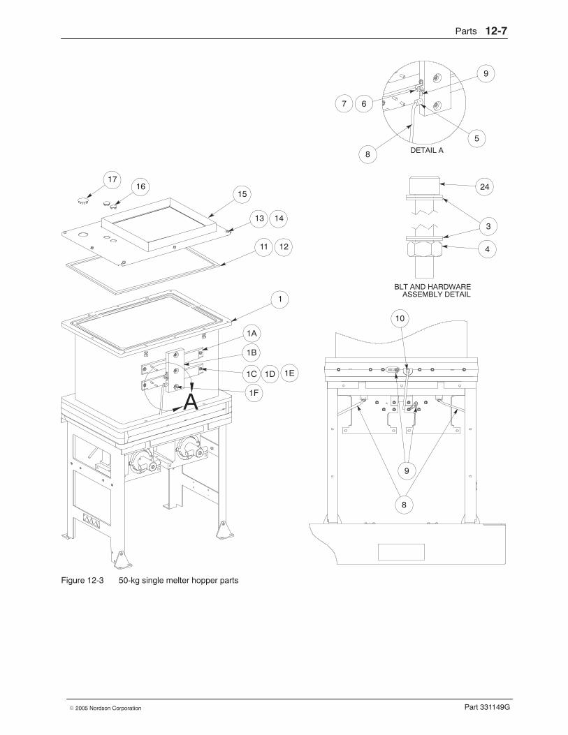
Parts 12-7
Part 331149G� 2005 Nordson Corporation
BLT AND HARDWAREASSEMBLY DETAIL
DETAIL A
A
1
1A
5
1B
9
67
24
4
3
10
9
11
15
12
1617
13 14
1C 1D 1E
1F
8
8
Figure 12-3 50-kg single melter hopper parts
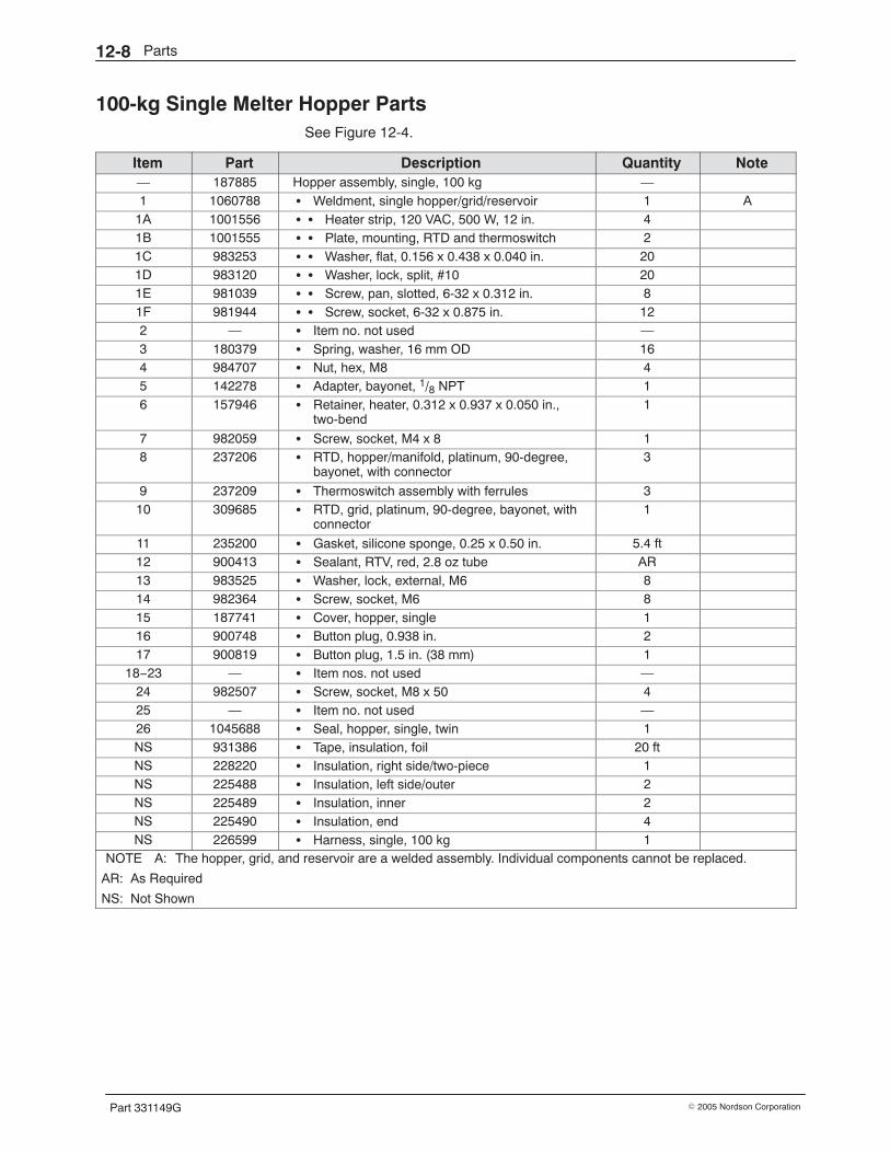
Parts12-8
Part 331149G � 2005 Nordson Corporation
100-kg Single Melter Hopper Parts See Figure 12-4.
Item Part Description Quantity Note— 187885 Hopper assembly, single, 100 kg —1 1060788 � Weldment, single hopper/grid/reservoir 1 A
1A 1001556 � � Heater strip, 120 VAC, 500 W, 12 in. 41B 1001555 � � Plate, mounting, RTD and thermoswitch 21C 983253 � � Washer, flat, 0.156 x 0.438 x 0.040 in. 201D 983120 � � Washer, lock, split, #10 201E 981039 � � Screw, pan, slotted, 6-32 x 0.312 in. 81F 981944 � � Screw, socket, 6-32 x 0.875 in. 122 — � Item no. not used —3 180379 � Spring, washer, 16 mm OD 164 984707 � Nut, hex, M8 45 142278 � Adapter, bayonet, 1/8 NPT 16 157946 � Retainer, heater, 0.312 x 0.937 x 0.050 in.,
two-bend1
7 982059 � Screw, socket, M4 x 8 18 237206 � RTD, hopper/manifold, platinum, 90-degree,
bayonet, with connector3
9 237209 � Thermoswitch assembly with ferrules 310 309685 � RTD, grid, platinum, 90-degree, bayonet, with
connector1
11 235200 � Gasket, silicone sponge, 0.25 x 0.50 in. 5.4 ft12 900413 � Sealant, RTV, red, 2.8 oz tube AR13 983525 � Washer, lock, external, M6 814 982364 � Screw, socket, M6 815 187741 � Cover, hopper, single 116 900748 � Button plug, 0.938 in. 217 900819 � Button plug, 1.5 in. (38 mm) 1
18−23 — � Item nos. not used —24 982507 � Screw, socket, M8 x 50 425 — � Item no. not used —26 1045688 � Seal, hopper, single, twin 1NS 931386 � Tape, insulation, foil 20 ftNS 228220 � Insulation, right side/two-piece 1NS 225488 � Insulation, left side/outer 2NS 225489 � Insulation, inner 2NS 225490 � Insulation, end 4NS 226599 � Harness, single, 100 kg 1
NOTE A: The hopper, grid, and reservoir are a welded assembly. Individual components cannot be replaced.
AR: As Required
NS: Not Shown
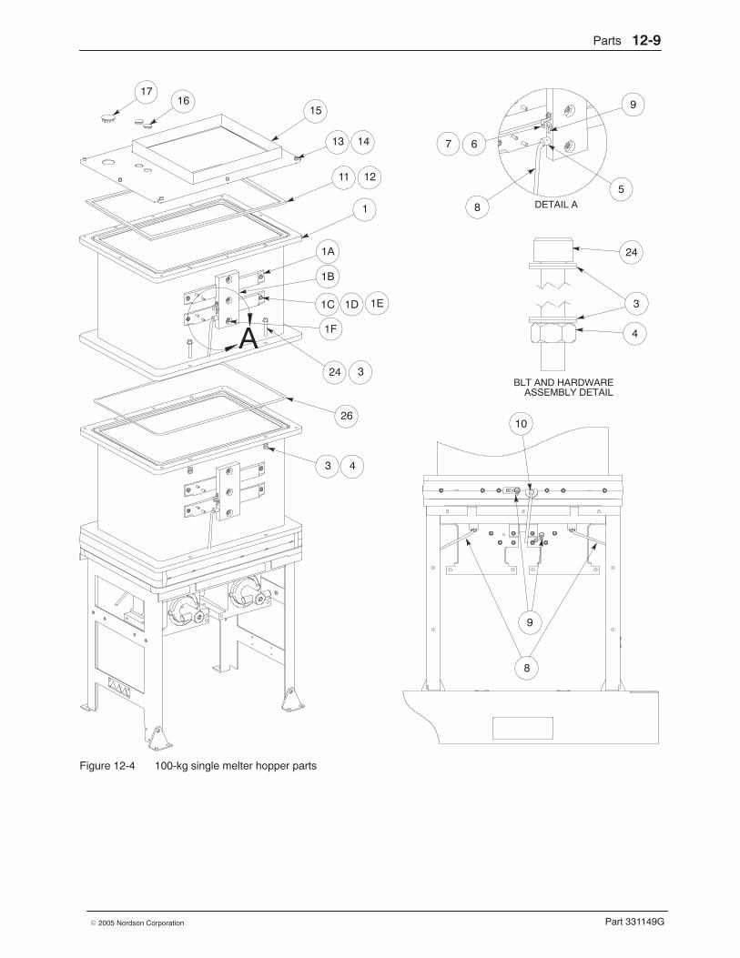
Parts 12-9
Part 331149G� 2005 Nordson Corporation
BLT AND HARDWAREASSEMBLY DETAIL
DETAIL A
A
1
3 4
1A
5
1B
9
67
24
4
3
10
9
11
15
12
1617
13 14
24 3
1C 1D 1E
1F
26
8
8
Figure 12-4 100-kg single melter hopper parts
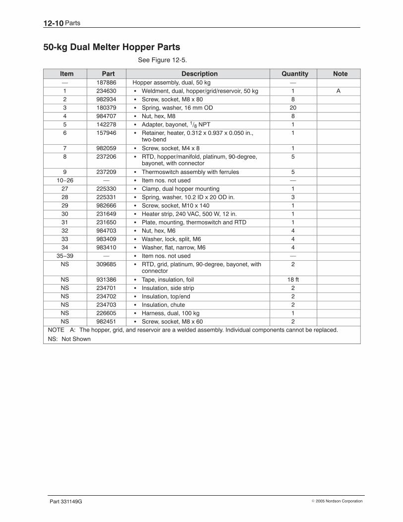
Parts12-10
Part 331149G � 2005 Nordson Corporation
50-kg Dual Melter Hopper Parts See Figure 12-5.
Item Part Description Quantity Note— 187886 Hopper assembly, dual, 50 kg —1 234630 � Weldment, dual, hopper/grid/reservoir, 50 kg 1 A2 982934 � Screw, socket, M8 x 80 83 180379 � Spring, washer, 16 mm OD 204 984707 � Nut, hex, M8 85 142278 � Adapter, bayonet, 1/8 NPT 16 157946 � Retainer, heater, 0.312 x 0.937 x 0.050 in.,
two-bend1
7 982059 � Screw, socket, M4 x 8 18 237206 � RTD, hopper/manifold, platinum, 90-degree,
bayonet, with connector5
9 237209 � Thermoswitch assembly with ferrules 510−26 — � Item nos. not used —
27 225330 � Clamp, dual hopper mounting 128 225331 � Spring, washer, 10.2 ID x 20 OD in. 329 982666 � Screw, socket, M10 x 140 130 231649 � Heater strip, 240 VAC, 500 W, 12 in. 131 231650 � Plate, mounting, thermoswitch and RTD 132 984703 � Nut, hex, M6 433 983409 � Washer, lock, split, M6 434 983410 � Washer, flat, narrow, M6 4
35−39 — � Item nos. not used —NS 309685 � RTD, grid, platinum, 90-degree, bayonet, with
connector2
NS 931386 � Tape, insulation, foil 18 ftNS 234701 � Insulation, side strip 2NS 234702 � Insulation, top/end 2NS 234703 � Insulation, chute 2NS 226605 � Harness, dual, 100 kg 1NS 982451 � Screw, socket, M8 x 60 2
NOTE A: The hopper, grid, and reservoir are a welded assembly. Individual components cannot be replaced.
NS: Not Shown
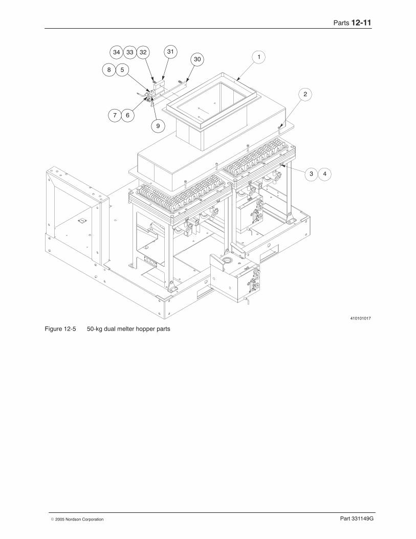
Parts 12-11
Part 331149G� 2005 Nordson Corporation
410101017
1
2
31
5
3230
9
3334
8
3 4
67
Figure 12-5 50-kg dual melter hopper parts

Parts12-12
Part 331149G � 2005 Nordson Corporation
100-kg Dual Melter Hopper Parts See Figure 12-6.
Item Part Description Quantity Note— 329091 Hopper assembly, dual, 100 kg —1 1060787 � Weldment, dual, hopper/grid/reservoir, 100 kg — A
1A 1001376 � � Heater strip, 120 VAC, 1000 W, 23.75 in. 21B 1001555 � � Plate, mounting, RTD and thermoswitch 11C 983253 � � Washer, flat, 0.156 x 0.438 x 0.040 in. 101D 983120 � � Washer, lock, split, #10 101E 981039 � � Screw, pan, slotted, 6-32 x 0.312 in. 41F 981944 � � Screw, socket, 6-32 x 0.875 in. 62−4 — � Item nos. not used —5 142278 � Adapter, bayonet, 1/8 NPT 16 157946 � Retainer, heater, 0.312 x 0.937 x 0.050 in.,
two-bend1
7 982059 � Screw, socket, M4 x 8 18 237206 � RTD, hopper/manifold, platinum, 90-degree,
bayonet, with connector5
9 237209 � Thermoswitch assembly with ferrules 510 309685 � RTD, grid, platinum, 90-degree, bayonet, with
connector2
11 235200 � Gasket, silicone sponge, 0.25 x 0.50 in. 9.2 ft12 900413 � Sealant, RTV, red, 2.8 oz tube AR13 983525 � Washer, lock, external, M6 1414 982176 � Screw, socket, M6 x 16 1415 187741 � Cover, hopper, single 216 900748 � Button plug, 0.938 in. 417 900819 � Button plug, 1.5 in. (38 mm) 2NS 931386 � Tape, insulation, foil 18 ftNS 228220 � Insulation, right side/two-piece 2NS 225592 � Insulation, top/end or outer 1NS 225591 � Insulation, inner 1NS 225590 � Insulation, ends 2NS 226605 � Harness, dual, 100 kg 1
NOTE A: The hopper, grid, and reservoir are a welded assembly. Individual components cannot be replaced.
AR: As Required
NS: Not Shown
Parts 12-13
Part 331149G� 2005 Nordson Corporation
A
DETAIL A
5
9
6 7
1
1A
1B
9
11
15
12
1617
13 14
1C 1D 1E
1F
10
8 8
9 9
8
Figure 12-6 100-kg dual melter hopper parts

Parts12-14
Part 331149G � 2005 Nordson Corporation
200-kg Dual Melter Hopper Parts See Figure 12-7.
Item Part Description Quantity Note— 329086 Hopper assembly, dual, 200 kg —1 1001375 � Weldment, dual hopper/grid/reservoir 1 A
1A 1001376 � � Heater strip, 120 VAC, 1000 W, 23.75 in. 41B 1001555 � � Plate, mounting, RTD and thermoswitch 21C 983253 � � Washer, flat, 0.156 x 0.438 x 0.040 in. 201D 983120 � � Washer, lock, split, #10 201E 981039 � � Screw, pan, slotted, 6-32 x 0.312 in. 81F 981944 � � Screw, socket, 6-32 x 0.875 in. 122 — � Item no. not used —3 180379 � Spring, washer, 16 mm OD 324 984707 � Nut, hex, M8 85 142278 � Adapter, bayonet, 1/8 NPT 26 157946 � Retainer, heater, 0.312 x 0.937 x 0.050 in.,
two-bend2
7 982059 � Screw, socket, M4 x 8 28 237206 � RTD, hopper/manifold, platinum, 90-degree,
bayonet, with connector6
9 237209 � Thermoswitch assembly with ferrules 610 309685 � RTD, grid, platinum, 90-degree, bayonet, with
connector2
11 235200 � Gasket, silicone sponge, 0.25 x 0.50 in. 9.2 ft12 900413 � Sealant, RTV, red, 2.8 oz tube AR13 983525 � Washer, lock, external, M6 1414 982364 � Screw, socket, M6 1415 187741 � Cover, hopper 216 900748 � Button plug, 0.938 in. 417 900819 � Button plug, 1.5 in. (38 mm) 2
18−23 — � Item nos. not used —24 982507 � Screw, socket, M8 x 50 825 — � Item no. not used —26 1045690 � Seal, hopper, dual 1NS 931386 � Tape, insulation, foil 30 ftNS 228220 � Insulation, right side/two-piece 2NS 225592 � Insulation, top/end or outer 2NS 225591 � Insulation, inner 2NS 225590 � Insulation, ends 4NS 226617 � Harness, twin, 100 kg 1
NOTE A: The hopper, grid, and reservoir are a welded assembly. Individual components cannot be replaced.
AR: As Required
NS: Not Shown
Parts 12-15
Part 331149G� 2005 Nordson Corporation
A
BLT AND HARDWAREASSEMBLY DETAIL
DETAIL A
5
9
6 7
24
4
3
1
3 4
1A
1B
9
11
15
12
1617 13 14
24 3
1C 1D 1E
1F
26
10
8 8
9 9
8
Figure 12-7 200-kg dual melter hopper parts
Parts12-16
Part 331149G � 2005 Nordson Corporation
25-kg Twin Melter Hopper Parts See Figure 12-8.
Item Part Description Quantity Note— 187889 Hopper assembly, twin, 25 kg —1 232157 � Weldment, single hopper/grid/reservoir 2 A2 982042 � Screw, socket, M8 x 75 83 180379 � Spring, washer, 16 mm OD 244 984707 � Nut, hex, M8 85 142278 � Adapter, bayonet, 1/8 NPT 26 157946 � Retainer, heater, 0.312 x 0.937 x 0.050 in.,
two-bend2
7 982059 � Screw, socket, M4 x 8 28 237206 � RTD, hopper/manifold, platinum, 90-degree,
bayonet, with connector6
9 237209 � Thermoswitch assembly with ferrules 610−29 — � Item nos. not used —
30 231649 � Heater, 12 in. strip, 240 VAC, 500 W 231 231650 � Plate, mounting, thermoswitch and RTD 232 984703 � Nut, hex, M6 833 983409 � Washer, lock, split, M6 834 983410 � Washer, flat, narrow, M6 8
35−39 — � Item nos. not used —NS 309685 � RTD, grid, platinum, 90-degree, bayonet, with
connector2
NS 931386 � Tape, insulation, foil 28 ftNS 232158 � Insulation, right side strip 2NS 232159 � Insulation, left side strip 2NS 232160 � Insulation, chute 4NS 232161 � Insulation, top/end 2NS 226614 � Harness, twin, 50 kg 1NS 982451 � Screw, socket, M8 x 60 2
NOTE A: The hopper, grid, and reservoir are a welded assembly. Individual components cannot be replaced.
NS: Not Shown
Parts 12-17
Part 331149G� 2005 Nordson Corporation
410101020
1
2
31
5
3230
9
3 4
67
8
3334
Figure 12-8 25-kg twin melter hopper parts
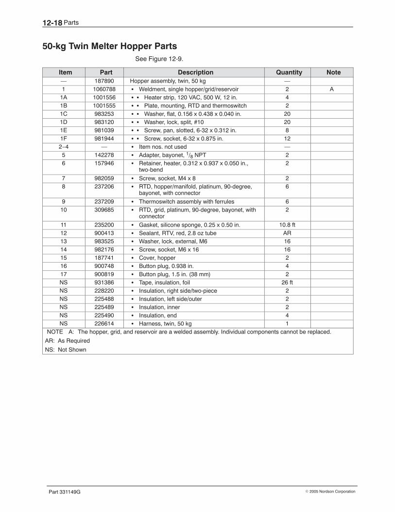
Parts12-18
Part 331149G � 2005 Nordson Corporation
50-kg Twin Melter Hopper Parts See Figure 12-9.
Item Part Description Quantity Note— 187890 Hopper assembly, twin, 50 kg —1 1060788 � Weldment, single hopper/grid/reservoir 2 A
1A 1001556 � � Heater strip, 120 VAC, 500 W, 12 in. 41B 1001555 � � Plate, mounting, RTD and thermoswitch 21C 983253 � � Washer, flat, 0.156 x 0.438 x 0.040 in. 201D 983120 � � Washer, lock, split, #10 201E 981039 � � Screw, pan, slotted, 6-32 x 0.312 in. 81F 981944 � � Screw, socket, 6-32 x 0.875 in. 122−4 — � Item nos. not used —5 142278 � Adapter, bayonet, 1/8 NPT 26 157946 � Retainer, heater, 0.312 x 0.937 x 0.050 in.,
two-bend2
7 982059 � Screw, socket, M4 x 8 28 237206 � RTD, hopper/manifold, platinum, 90-degree,
bayonet, with connector6
9 237209 � Thermoswitch assembly with ferrules 610 309685 � RTD, grid, platinum, 90-degree, bayonet, with
connector2
11 235200 � Gasket, silicone sponge, 0.25 x 0.50 in. 10.8 ft12 900413 � Sealant, RTV, red, 2.8 oz tube AR13 983525 � Washer, lock, external, M6 1614 982176 � Screw, socket, M6 x 16 1615 187741 � Cover, hopper 216 900748 � Button plug, 0.938 in. 417 900819 � Button plug, 1.5 in. (38 mm) 2NS 931386 � Tape, insulation, foil 26 ftNS 228220 � Insulation, right side/two-piece 2NS 225488 � Insulation, left side/outer 2NS 225489 � Insulation, inner 2NS 225490 � Insulation, end 4NS 226614 � Harness, twin, 50 kg 1
NOTE A: The hopper, grid, and reservoir are a welded assembly. Individual components cannot be replaced.
AR: As Required
NS: Not Shown
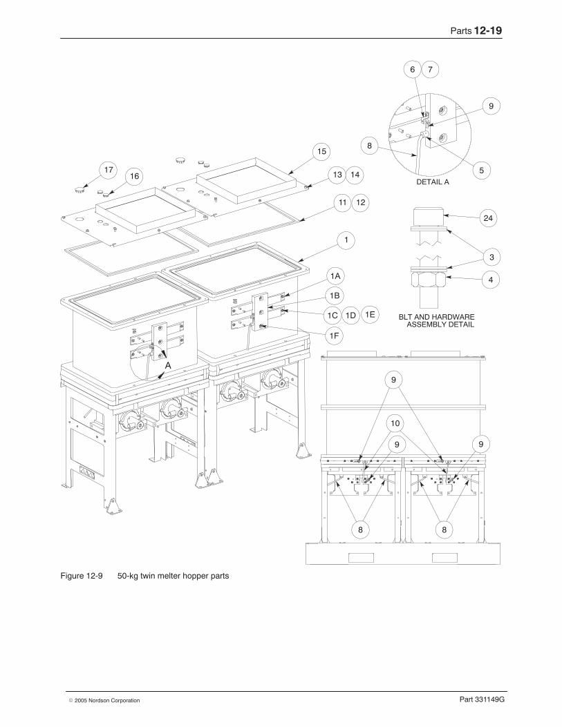
Parts 12-19
Part 331149G� 2005 Nordson Corporation
A
BLT AND HARDWAREASSEMBLY DETAIL
DETAIL A
9
6 7
24
4
3
9
10
8 8
9 9
1
1A
1B
11
15
12
1617
13 14
1C 1D 1E
1F
5
8
Figure 12-9 50-kg twin melter hopper parts

Parts12-20
Part 331149G � 2005 Nordson Corporation
100-kg Twin Melter Hopper Parts See Figure 12-10.
Item Part Description Quantity Note— 187891 Hopper assembly, twin, 100 kg —1 1060788 � Weldment, single hopper/grid/reservoir 2 A
1A 1001556 � � Heater strip, 120 VAC, 500 W, 12 in. 81B 1001555 � � Plate, mounting, RTD and thermoswitch 41C 983253 � � Washer, flat, 0.156 x 0.438 x 0.040 in. 401D 983120 � � Washer, lock, split, #10 401E 981039 � � Screw, pan, slotted, 6-32 x 0.312 in. 161F 981944 � � Screw, socket, 6-32 x 0.875 in. 242 — � Item no. not used —3 180379 � Spring, washer, 16 mm OD 324 984707 � Nut, hex, M8 85 142278 � Adapter, bayonet, 1/8 NPT 26 157946 � Retainer, heater, 0.312 x 0.937 x 0.050 in.,
two-bend2
7 982059 � Screw, socket, M4 x 8 28 237206 � RTD, hopper/manifold, platinum, 90-degree,
bayonet, with connector6
9 237209 � Thermoswitch assembly with ferrules 610 309685 � RTD, grid, platinum, 90-degree, bayonet, with
connector2
11 235200 � Gasket, silicone sponge, 0.25 x 0.50 in. 10.8 ft12 900413 � Sealant, RTV, red, 2.8 oz tube AR13 983525 � Washer, lock, external, M6 1614 982364 � Screw, socket, M6 1615 187741 � Cover, hopper 216 900748 � Button plug, 0.938 in. 417 900819 � Button plug, 1.5 in. (38 mm) 2
18−23 — � Item nos. not used —24 982507 � Screw, socket, M8 x 50 825 — � Item no. not used —26 1045688 � Seal, hopper, single, twin 1NS 931386 � Tape, insulation, foil 28 ftNS 228220 � Insulation, right side/two-piece 2NS 225488 � Insulation, left side/outer 4NS 225489 � Insulation, inner 4NS 225490 � Insulation, end 8NS 226617 � Harness, twin, 100 kg 1
NOTE A: The hopper, grid, and reservoir are a welded assembly. Individual components cannot be replaced.
AR: As Required
NS: Not Shown
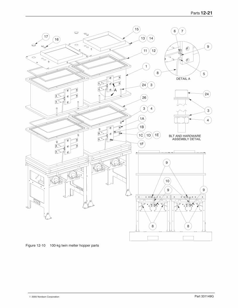
Parts 12-21
Part 331149G� 2005 Nordson Corporation
A
BLT AND HARDWAREASSEMBLY DETAIL
DETAIL A
9
6 7
24
4
3
9
10
8 8
9 9
1
3 4
1A
1B
11
15
12
1617 13 14
24 3
1C 1D 1E
1F
26
58
Figure 12-10 100-kg twin melter hopper parts
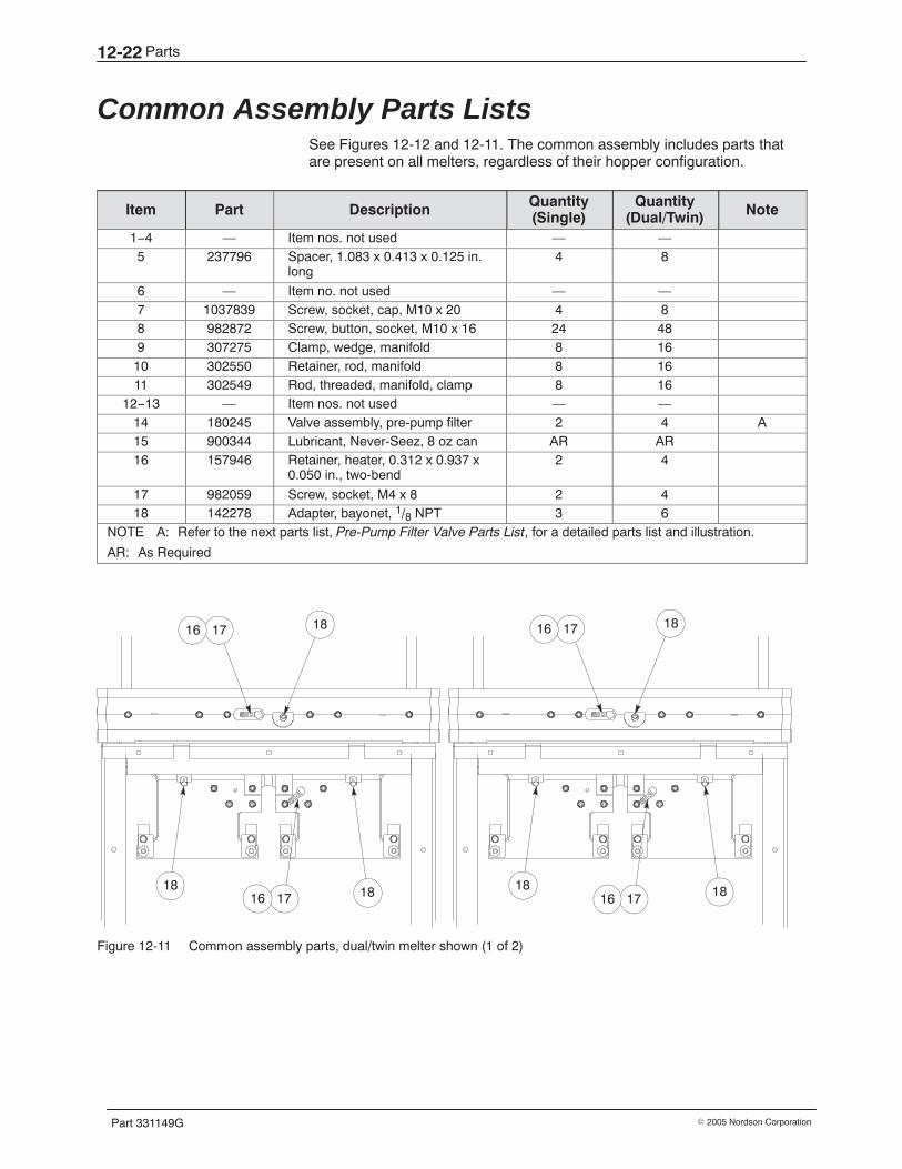
Parts12-22
Part 331149G � 2005 Nordson Corporation
Common Assembly Parts Lists See Figures 12-12 and 12-11. The common assembly includes parts thatare present on all melters, regardless of their hopper configuration.
Item Part Description Quantity(Single)
Quantity(Dual/Twin) Note
1−4 — Item nos. not used — —5 237796 Spacer, 1.083 x 0.413 x 0.125 in.
long4 8
6 — Item no. not used — —7 1037839 Screw, socket, cap, M10 x 20 4 88 982872 Screw, button, socket, M10 x 16 24 489 307275 Clamp, wedge, manifold 8 1610 302550 Retainer, rod, manifold 8 1611 302549 Rod, threaded, manifold, clamp 8 16
12−13 — Item nos. not used — —14 180245 Valve assembly, pre-pump filter 2 4 A15 900344 Lubricant, Never-Seez, 8 oz can AR AR16 157946 Retainer, heater, 0.312 x 0.937 x
0.050 in., two-bend2 4
17 982059 Screw, socket, M4 x 8 2 418 142278 Adapter, bayonet, 1/8 NPT 3 6
NOTE A: Refer to the next parts list, Pre-Pump Filter Valve Parts List, for a detailed parts list and illustration.
AR: As Required
1716 18
181716 18 18
1716 18
1716 18
Figure 12-11 Common assembly parts, dual/twin melter shown (1 of 2)
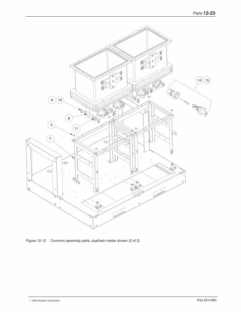
Parts 12-23
Part 331149G� 2005 Nordson Corporation
5
14 15
7
108
9
11
Figure 12-12 Common assembly parts, dual/twin melter shown (2 of 2)
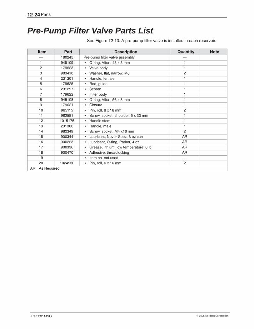
Parts12-24
Part 331149G � 2005 Nordson Corporation
Pre-Pump Filter Valve Parts List See Figure 12-13. A pre-pump filter valve is installed in each reservoir.
Item Part Description Quantity Note— 180245 Pre-pump filter valve assembly —1 945109 � O-ring, Viton, 43 x 3 mm 12 179623 � Valve body 13 983410 � Washer, flat, narrow, M6 24 231301 � Handle, female 15 179625 � Rod, guide 16 231297 � Screen 17 179622 � Filter body 18 945108 � O-ring, Viton, 56 x 3 mm 19 179621 � Closure 110 985115 � Pin, roll, 8 x 16 mm 211 982581 � Screw, socket, shoulder, 5 x 30 mm 112 1015175 � Handle stem 113 231300 � Handle, male 114 982349 � Screw, socket, M4 x16 mm 215 900344 � Lubricant, Never-Seez, 8 oz can AR16 900223 � Lubricant, O-ring, Parker, 4 oz AR17 900336 � Grease, lithium, low temperature, 6 lb AR18 900470 � Adhesive, threadlocking AR19 — � Item no. not used —20 1024530 � Pin, roll, 6 x 16 mm 2
AR: As Required
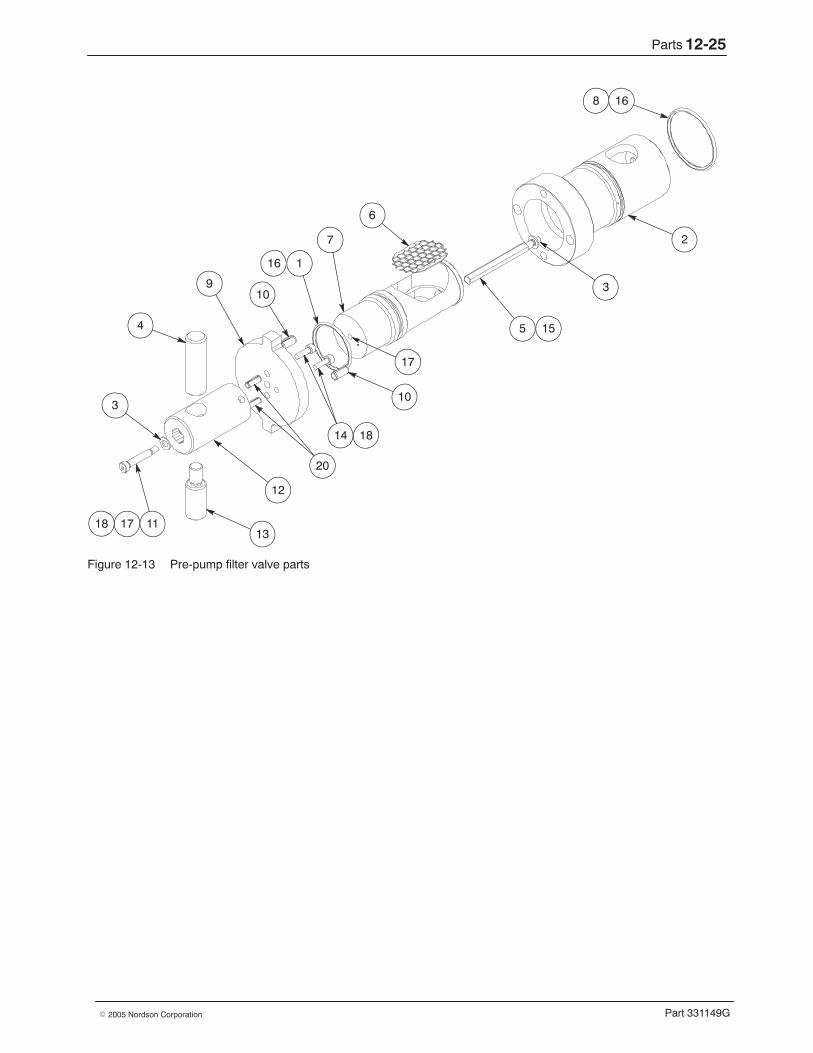
Parts 12-25
Part 331149G� 2005 Nordson Corporation
13
12
10
17
5
3
2
11
3
4
910
1
7
6
16
16
14 18
1718
8
15
20
Figure 12-13 Pre-pump filter valve parts

Parts12-26
Part 331149G � 2005 Nordson Corporation
This page intentionally left blank.
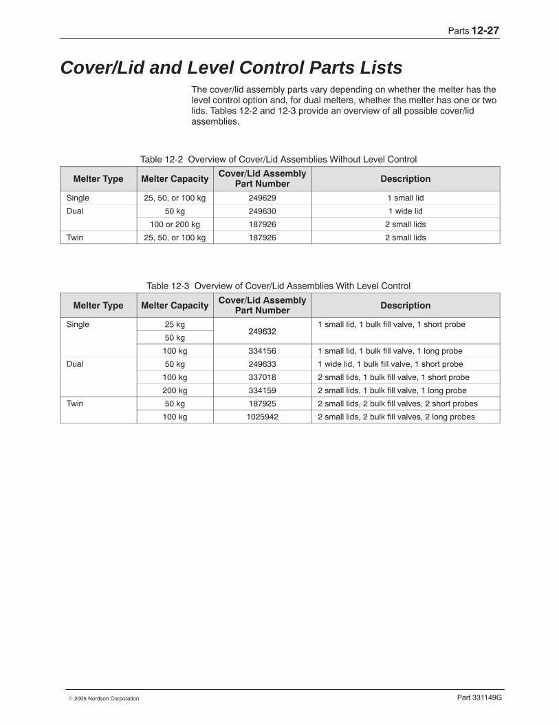
Parts 12-27
Part 331149G� 2005 Nordson Corporation
Cover/Lid and Level Control Parts Lists The cover/lid assembly parts vary depending on whether the melter has thelevel control option and, for dual melters, whether the melter has one or twolids. Tables 12-2 and 12-3 provide an overview of all possible cover/lidassemblies.
Table 12-2 Overview of Cover/Lid Assemblies Without Level Control
Melter Type Melter Capacity Cover/Lid AssemblyPart Number Description
Single 25, 50, or 100 kg 249629 1 small lid
Dual 50 kg 249630 1 wide lid
100 or 200 kg 187926 2 small lids
Twin 25, 50, or 100 kg 187926 2 small lids
Table 12-3 Overview of Cover/Lid Assemblies With Level Control
Melter Type Melter Capacity Cover/Lid AssemblyPart Number Description
Single 25 kg249632
1 small lid, 1 bulk fill valve, 1 short probeg
50 kg249632
, , p
100 kg 334156 1 small lid, 1 bulk fill valve, 1 long probe
Dual 50 kg 249633 1 wide lid, 1 bulk fill valve, 1 short probe
100 kg 337018 2 small lids, 1 bulk fill valve, 1 short probe
200 kg 334159 2 small lids, 1 bulk fill valve, 1 long probe
Twin 50 kg 187925 2 small lids, 2 bulk fill valves, 2 short probes
100 kg 1025942 2 small lids, 2 bulk fill valves, 2 long probes
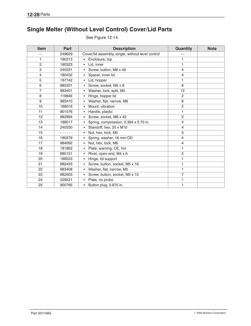
Parts12-28
Part 331149G � 2005 Nordson Corporation
Single Melter (Without Level Control) Cover/Lid Parts See Figure 12-14.
Item Part Description Quantity Note— 249629 Cover/lid assembly, single, without level control —1 180313 � Enclosure, top 12 180323 � Lid, inner 13 240331 � Screw, button, M6 x 45 44 180432 � Spacer, inner lid 45 187742 � Lid, hopper 16 982201 � Screw, socket, M5 x 8 87 983401 � Washer, lock, split, M5 128 119949 � Hinge, hopper lid 29 983410 � Washer, flat, narrow, M6 810 188016 � Mount, vibration 211 901576 � Handle, plastic 112 982894 � Screw, socket, M6 x 45 213 188017 � Spring, compression, 0.394 x 0.70 in. 414 240330 � Standoff, hex, 20 x M10 415 - - - - - - � Nut, hex, lock, M5 316 180379 � Spring, washer, 16 mm OD 417 984092 � Nut, hex, lock, M6 418 181862 � Plate, warning, CE, hot 119 985151 � Rivet, open-end, M4 x 6 220 188033 � Hinge, lid support 121 982433 � Screw, button, socket, M5 x 16 122 983408 � Washer, flat, narrow, M5 123 982503 � Screw, button, socket, M5 x 10 724 229521 � Plate, no probe 125 900765 � Button plug, 0.875 in. 1
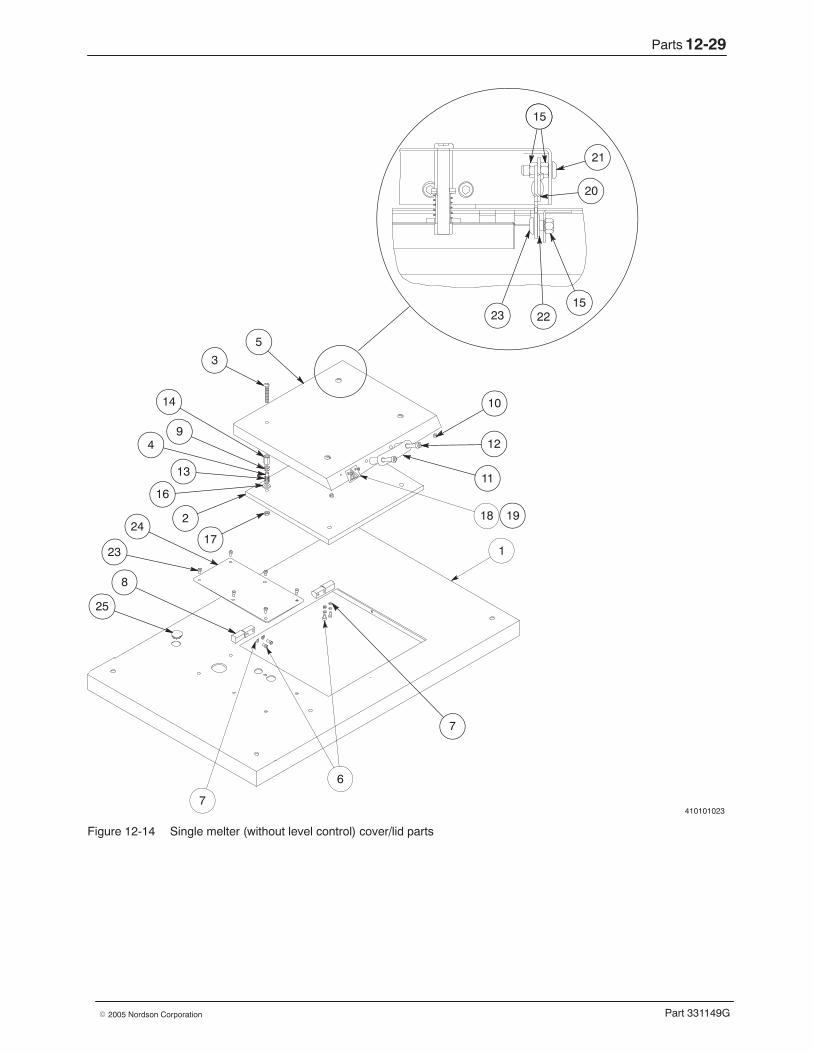
Parts 12-29
Part 331149G� 2005 Nordson Corporation
410101023
18
25
8
24
6
7
1
10
12
11
5
14
19
4
2
3
21
20
23 2215
15
17
16
9
13
23
7
Figure 12-14 Single melter (without level control) cover/lid parts
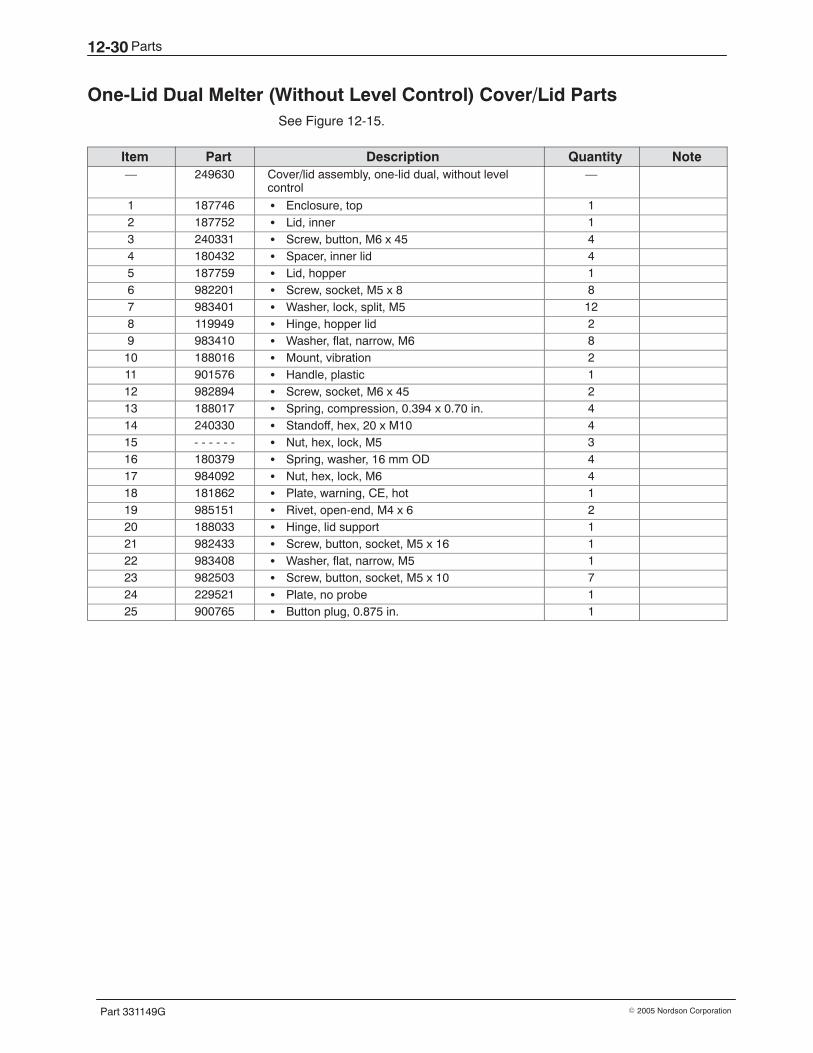
Parts12-30
Part 331149G � 2005 Nordson Corporation
One-Lid Dual Melter (Without Level Control) Cover/Lid Parts See Figure 12-15.
Item Part Description Quantity Note— 249630 Cover/lid assembly, one-lid dual, without level
control—
1 187746 � Enclosure, top 12 187752 � Lid, inner 13 240331 � Screw, button, M6 x 45 44 180432 � Spacer, inner lid 45 187759 � Lid, hopper 16 982201 � Screw, socket, M5 x 8 87 983401 � Washer, lock, split, M5 128 119949 � Hinge, hopper lid 29 983410 � Washer, flat, narrow, M6 810 188016 � Mount, vibration 211 901576 � Handle, plastic 112 982894 � Screw, socket, M6 x 45 213 188017 � Spring, compression, 0.394 x 0.70 in. 414 240330 � Standoff, hex, 20 x M10 415 - - - - - - � Nut, hex, lock, M5 316 180379 � Spring, washer, 16 mm OD 417 984092 � Nut, hex, lock, M6 418 181862 � Plate, warning, CE, hot 119 985151 � Rivet, open-end, M4 x 6 220 188033 � Hinge, lid support 121 982433 � Screw, button, socket, M5 x 16 122 983408 � Washer, flat, narrow, M5 123 982503 � Screw, button, socket, M5 x 10 724 229521 � Plate, no probe 125 900765 � Button plug, 0.875 in. 1
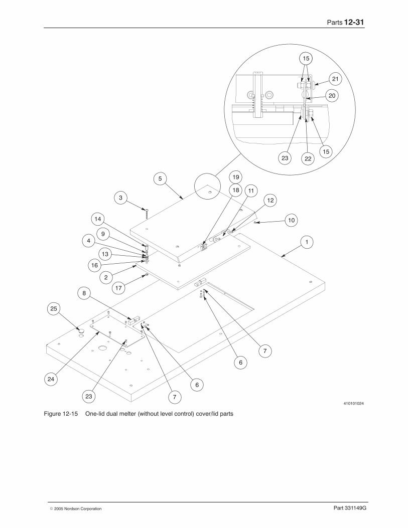
Parts 12-31
Part 331149G� 2005 Nordson Corporation
410101024
25
8
24
23 7
6
6
7
1
10
12
1118
5
14
19
4
2
3
21
20
23 2215
15
17
16
9
13
Figure 12-15 One-lid dual melter (without level control) cover/lid parts
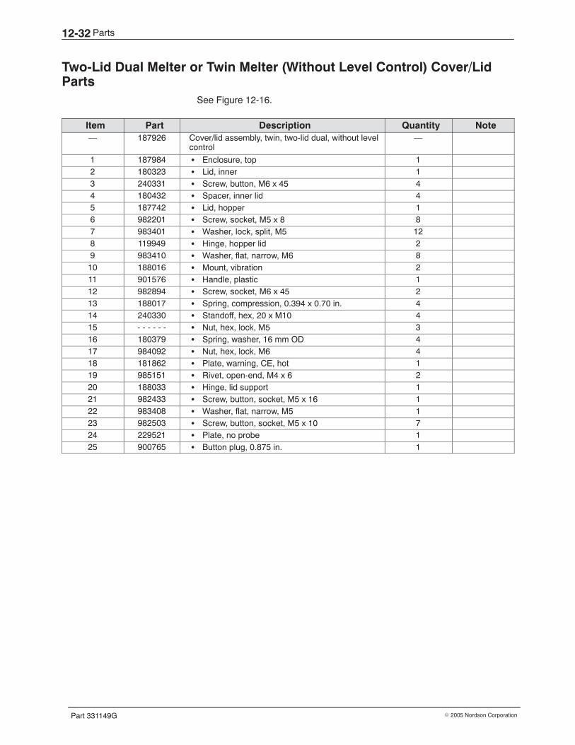
Parts12-32
Part 331149G � 2005 Nordson Corporation
Two-Lid Dual Melter or Twin Melter (Without Level Control) Cover/LidParts
See Figure 12-16.
Item Part Description Quantity Note— 187926 Cover/lid assembly, twin, two-lid dual, without level
control—
1 187984 � Enclosure, top 12 180323 � Lid, inner 13 240331 � Screw, button, M6 x 45 44 180432 � Spacer, inner lid 45 187742 � Lid, hopper 16 982201 � Screw, socket, M5 x 8 87 983401 � Washer, lock, split, M5 128 119949 � Hinge, hopper lid 29 983410 � Washer, flat, narrow, M6 810 188016 � Mount, vibration 211 901576 � Handle, plastic 112 982894 � Screw, socket, M6 x 45 213 188017 � Spring, compression, 0.394 x 0.70 in. 414 240330 � Standoff, hex, 20 x M10 415 - - - - - - � Nut, hex, lock, M5 316 180379 � Spring, washer, 16 mm OD 417 984092 � Nut, hex, lock, M6 418 181862 � Plate, warning, CE, hot 119 985151 � Rivet, open-end, M4 x 6 220 188033 � Hinge, lid support 121 982433 � Screw, button, socket, M5 x 16 122 983408 � Washer, flat, narrow, M5 123 982503 � Screw, button, socket, M5 x 10 724 229521 � Plate, no probe 125 900765 � Button plug, 0.875 in. 1
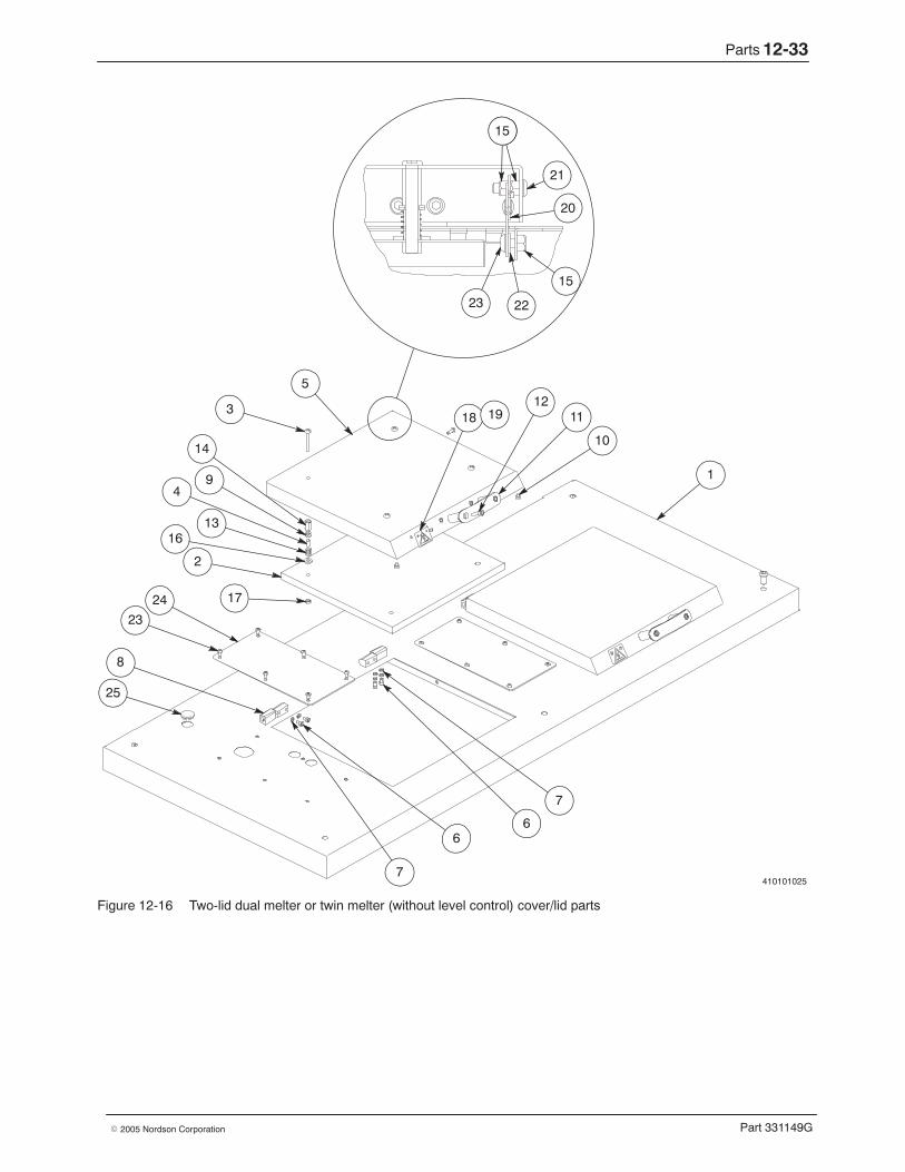
Parts 12-33
Part 331149G� 2005 Nordson Corporation
410101025
1
6
7
25
8
23
1724
2
49
14
5
11
10
1218 19
15
21
20
15
2223
6
7
1613
3
Figure 12-16 Two-lid dual melter or twin melter (without level control) cover/lid parts
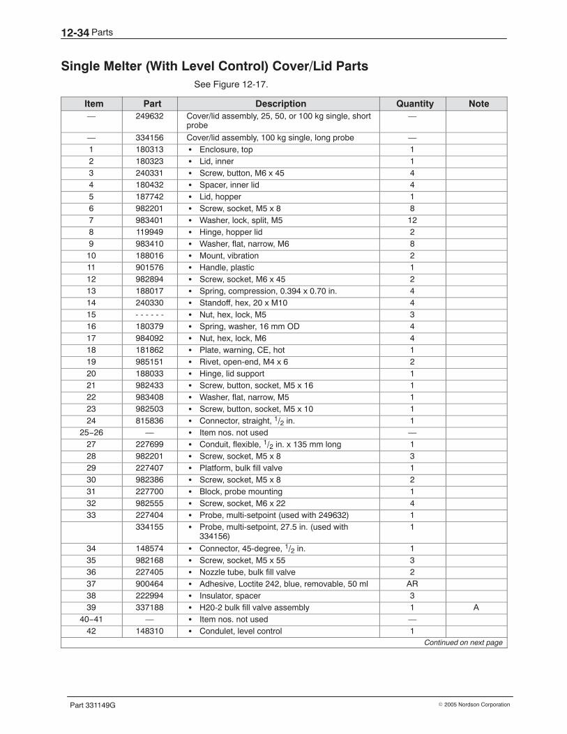
Parts12-34
Part 331149G � 2005 Nordson Corporation
Single Melter (With Level Control) Cover/Lid Parts See Figure 12-17.
Item Part Description Quantity Note— 249632 Cover/lid assembly, 25, 50, or 100 kg single, short
probe—
— 334156 Cover/lid assembly, 100 kg single, long probe —1 180313 � Enclosure, top 12 180323 � Lid, inner 13 240331 � Screw, button, M6 x 45 44 180432 � Spacer, inner lid 45 187742 � Lid, hopper 16 982201 � Screw, socket, M5 x 8 87 983401 � Washer, lock, split, M5 128 119949 � Hinge, hopper lid 29 983410 � Washer, flat, narrow, M6 810 188016 � Mount, vibration 211 901576 � Handle, plastic 112 982894 � Screw, socket, M6 x 45 213 188017 � Spring, compression, 0.394 x 0.70 in. 414 240330 � Standoff, hex, 20 x M10 415 - - - - - - � Nut, hex, lock, M5 316 180379 � Spring, washer, 16 mm OD 417 984092 � Nut, hex, lock, M6 418 181862 � Plate, warning, CE, hot 119 985151 � Rivet, open-end, M4 x 6 220 188033 � Hinge, lid support 121 982433 � Screw, button, socket, M5 x 16 122 983408 � Washer, flat, narrow, M5 123 982503 � Screw, button, socket, M5 x 10 124 815836 � Connector, straight, 1/2 in. 1
25−26 — � Item nos. not used —27 227699 � Conduit, flexible, 1/2 in. x 135 mm long 128 982201 � Screw, socket, M5 x 8 329 227407 � Platform, bulk fill valve 130 982386 � Screw, socket, M5 x 8 231 227700 � Block, probe mounting 132 982555 � Screw, socket, M6 x 22 433 227404 � Probe, multi-setpoint (used with 249632) 1
334155 � Probe, multi-setpoint, 27.5 in. (used with334156)
1
34 148574 � Connector, 45-degree, 1/2 in. 135 982168 � Screw, socket, M5 x 55 336 227405 � Nozzle tube, bulk fill valve 237 900464 � Adhesive, Loctite 242, blue, removable, 50 ml AR38 222994 � Insulator, spacer 339 337188 � H20-2 bulk fill valve assembly 1 A
40−41 — � Item nos. not used —42 148310 � Condulet, level control 1
Continued on next page
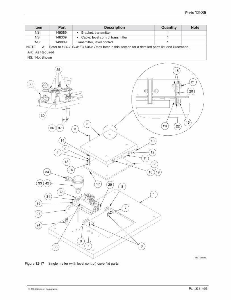
Parts 12-35
Part 331149G� 2005 Nordson Corporation
NoteQuantityDescriptionPartItemNS 149089 � Bracket, transmitter 1NS 148309 � Cable, level control transmitter 1NS 149089 Transmitter, level control 1
NOTE A: Refer to H20-2 Bulk Fill Valve Parts later in this section for a detailed parts list and illustration.
AR: As Required
NS: Not Shown
410101026
18
6
1
10
12
11
5
14
19
4
2
3
21
20
23 2215
15
17
16
9
13
35
39
30
3736 37
35
34
42
3231
24
28
27
38
33 29 8
7
78
Figure 12-17 Single melter (with level control) cover/lid parts
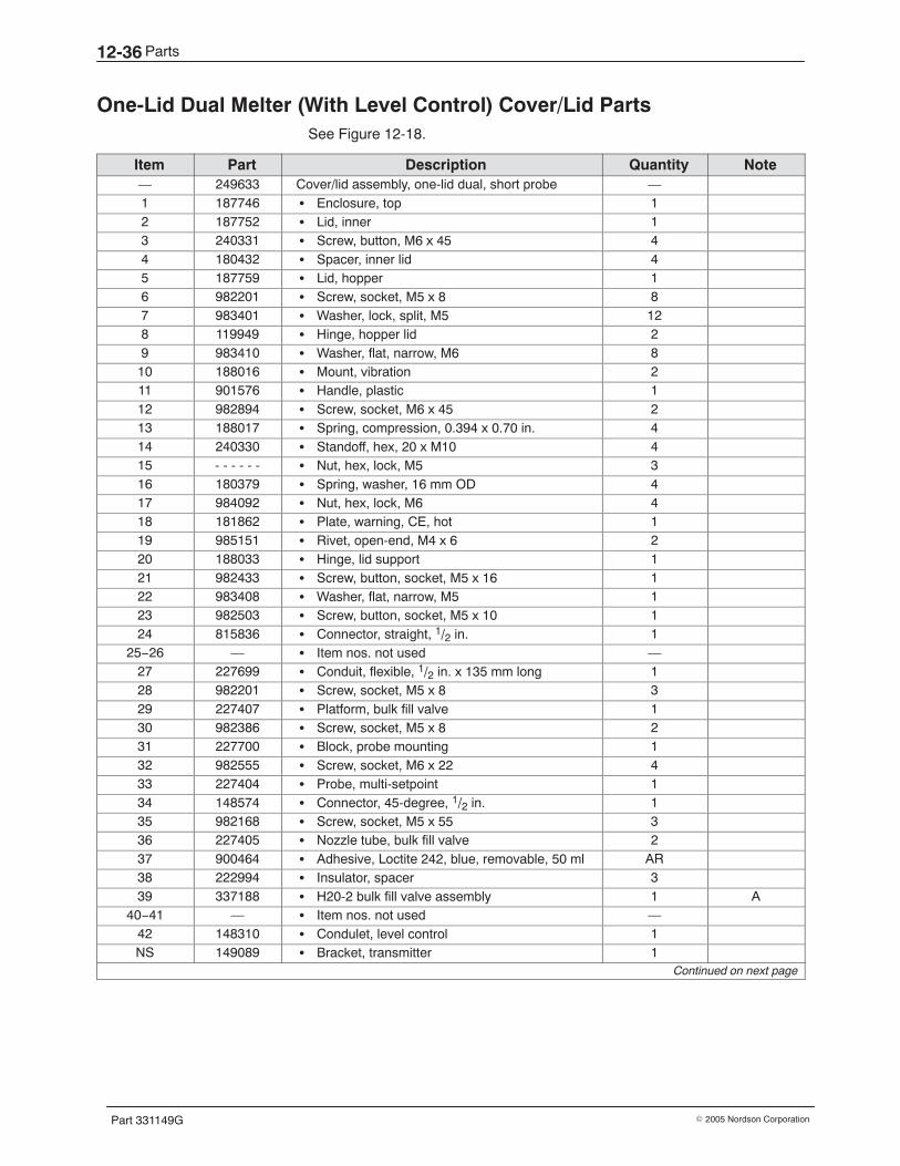
Parts12-36
Part 331149G � 2005 Nordson Corporation
One-Lid Dual Melter (With Level Control) Cover/Lid Parts See Figure 12-18.
Item Part Description Quantity Note— 249633 Cover/lid assembly, one-lid dual, short probe —1 187746 � Enclosure, top 12 187752 � Lid, inner 13 240331 � Screw, button, M6 x 45 44 180432 � Spacer, inner lid 45 187759 � Lid, hopper 16 982201 � Screw, socket, M5 x 8 87 983401 � Washer, lock, split, M5 128 119949 � Hinge, hopper lid 29 983410 � Washer, flat, narrow, M6 810 188016 � Mount, vibration 211 901576 � Handle, plastic 112 982894 � Screw, socket, M6 x 45 213 188017 � Spring, compression, 0.394 x 0.70 in. 414 240330 � Standoff, hex, 20 x M10 415 - - - - - - � Nut, hex, lock, M5 316 180379 � Spring, washer, 16 mm OD 417 984092 � Nut, hex, lock, M6 418 181862 � Plate, warning, CE, hot 119 985151 � Rivet, open-end, M4 x 6 220 188033 � Hinge, lid support 121 982433 � Screw, button, socket, M5 x 16 122 983408 � Washer, flat, narrow, M5 123 982503 � Screw, button, socket, M5 x 10 124 815836 � Connector, straight, 1/2 in. 1
25−26 — � Item nos. not used —27 227699 � Conduit, flexible, 1/2 in. x 135 mm long 128 982201 � Screw, socket, M5 x 8 329 227407 � Platform, bulk fill valve 130 982386 � Screw, socket, M5 x 8 231 227700 � Block, probe mounting 132 982555 � Screw, socket, M6 x 22 433 227404 � Probe, multi-setpoint 134 148574 � Connector, 45-degree, 1/2 in. 135 982168 � Screw, socket, M5 x 55 336 227405 � Nozzle tube, bulk fill valve 237 900464 � Adhesive, Loctite 242, blue, removable, 50 ml AR38 222994 � Insulator, spacer 339 337188 � H20-2 bulk fill valve assembly 1 A
40−41 — � Item nos. not used —42 148310 � Condulet, level control 1NS 149089 � Bracket, transmitter 1
Continued on next page
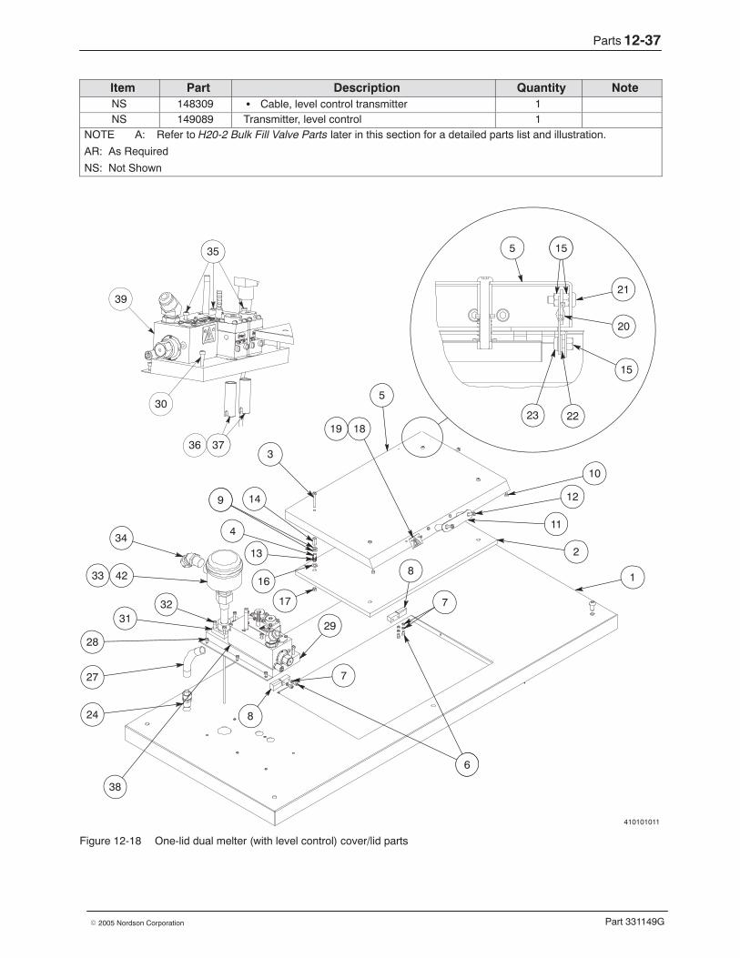
Parts 12-37
Part 331149G� 2005 Nordson Corporation
NoteQuantityDescriptionPartItemNS 148309 � Cable, level control transmitter 1NS 149089 Transmitter, level control 1
NOTE A: Refer to H20-2 Bulk Fill Valve Parts later in this section for a detailed parts list and illustration.
AR: As Required
NS: Not Shown
410101011
35
39
30
3736 37
35 5 15
21
20
15
2223
15
9
13
4
14
3
34
42
3231
24
28
27
38
33
5
17
10
12
11
1819
1
6
29
8
.
6
7
16
9
2
8
7
Figure 12-18 One-lid dual melter (with level control) cover/lid parts
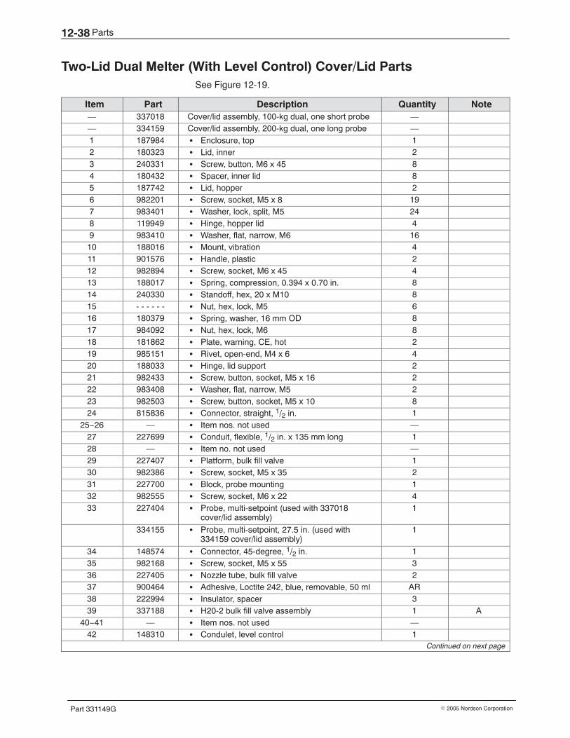
Parts12-38
Part 331149G � 2005 Nordson Corporation
Two-Lid Dual Melter (With Level Control) Cover/Lid Parts See Figure 12-19.
Item Part Description Quantity Note— 337018 Cover/lid assembly, 100-kg dual, one short probe —— 334159 Cover/lid assembly, 200-kg dual, one long probe —1 187984 � Enclosure, top 12 180323 � Lid, inner 23 240331 � Screw, button, M6 x 45 84 180432 � Spacer, inner lid 85 187742 � Lid, hopper 26 982201 � Screw, socket, M5 x 8 197 983401 � Washer, lock, split, M5 248 119949 � Hinge, hopper lid 49 983410 � Washer, flat, narrow, M6 1610 188016 � Mount, vibration 411 901576 � Handle, plastic 212 982894 � Screw, socket, M6 x 45 413 188017 � Spring, compression, 0.394 x 0.70 in. 814 240330 � Standoff, hex, 20 x M10 815 - - - - - - � Nut, hex, lock, M5 616 180379 � Spring, washer, 16 mm OD 817 984092 � Nut, hex, lock, M6 818 181862 � Plate, warning, CE, hot 219 985151 � Rivet, open-end, M4 x 6 420 188033 � Hinge, lid support 221 982433 � Screw, button, socket, M5 x 16 222 983408 � Washer, flat, narrow, M5 223 982503 � Screw, button, socket, M5 x 10 824 815836 � Connector, straight, 1/2 in. 1
25−26 — � Item nos. not used —27 227699 � Conduit, flexible, 1/2 in. x 135 mm long 128 — � Item no. not used —29 227407 � Platform, bulk fill valve 130 982386 � Screw, socket, M5 x 35 231 227700 � Block, probe mounting 132 982555 � Screw, socket, M6 x 22 433 227404 � Probe, multi-setpoint (used with 337018
cover/lid assembly)1
334155 � Probe, multi-setpoint, 27.5 in. (used with334159 cover/lid assembly)
1
34 148574 � Connector, 45-degree, 1/2 in. 135 982168 � Screw, socket, M5 x 55 336 227405 � Nozzle tube, bulk fill valve 237 900464 � Adhesive, Loctite 242, blue, removable, 50 ml AR38 222994 � Insulator, spacer 339 337188 � H20-2 bulk fill valve assembly 1 A
40−41 — � Item nos. not used —42 148310 � Condulet, level control 1
Continued on next page
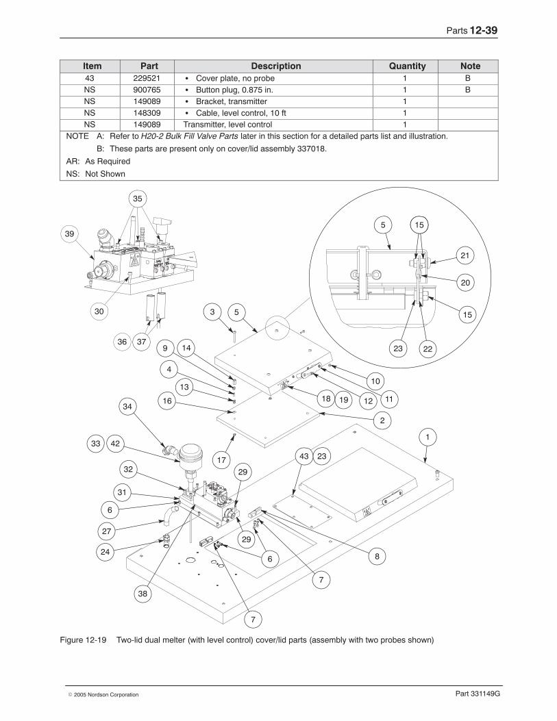
Parts 12-39
Part 331149G� 2005 Nordson Corporation
NoteQuantityDescriptionPartItem43 229521 � Cover plate, no probe 1 BNS 900765 � Button plug, 0.875 in. 1 BNS 149089 � Bracket, transmitter 1NS 148309 � Cable, level control, 10 ft 1NS 149089 Transmitter, level control 1
NOTE A: Refer to H20-2 Bulk Fill Valve Parts later in this section for a detailed parts list and illustration.
B: These parts are present only on cover/lid assembly 337018.
AR: As Required
NS: Not Shown
18 12
10
11
1
2
8
7
6
42
34
32
31
16
13
4
9
3
27
24
14
5
17
19
33
38
29
7
35
39
30
3736 37
35
29
43 23
6
5 15
21
20
15
2223
15
Figure 12-19 Two-lid dual melter (with level control) cover/lid parts (assembly with two probes shown)
Parts12-40
Part 331149G � 2005 Nordson Corporation
Twin Melter (With Level Control) Cover/Lid Parts See Figure 12-20.
Item Part Description Quantity Note— 187925 Cover/lid assembly, 50-kg twin, two short probes —— 1025942 Cover/lid assembly, 100-kg twin, two long probes —1 187984 � Enclosure, top 12 180323 � Lid, inner 23 240331 � Screw, button, M6 x 45 84 180432 � Spacer, inner lid 85 187742 � Lid, hopper 26 982201 � Screw, socket, M5 x 8 307 983401 � Washer, lock, split, M5 248 119949 � Hinge, hopper lid 49 983410 � Washer, flat, narrow, M6 1610 188016 � Mount, vibration 411 901576 � Handle, plastic 212 982894 � Screw, socket, M6 x 45 413 188017 � Spring, compression, 0.394 x 0.70 in. 814 240330 � Standoff, hex, 20 x M10 815 - - - - - - � Nut, hex, lock, M5 616 180379 � Spring, washer, 16 mm OD 817 984092 � Nut, hex, lock, M6 818 181862 � Plate, warning, CE, hot 219 985151 � Rivet, open-end, M4 x 6 420 188033 � Hinge, lid support 221 982433 � Screw, button, socket, M5 x 16 222 983408 � Washer, flat, narrow, M5 223 982503 � Screw, button, socket, M5 x 10 224 815836 � Connector, straight, 1/2 in. 2
25−26 — � Item nos. not used —27 227699 � Conduit, flexible, 1/2 in. x 135 mm long 228 — � Item no. not used —29 227407 � Platform, bulk fill valve 230 982386 � Screw, socket, M5 x 8 431 227700 � Block, probe mounting 232 982555 � Screw, socket, M6 x 22 833 227404 � Probe, multi-setpoint (used with 187925
cover/lid assembly)2
334155 � Probe, multi-setpoint, 27.5 in. (used with1025942 cover/lid assembly)
2
34 148574 � Connector, 45-degree, 1/2 in. 235 982168 � Screw, socket, M5 x 55 636 227405 � Nozzle tube, bulk fill valve 437 900464 � Adhesive, Loctite 242, blue, removable, 50 ml AR38 222994 � Insulator, spacer 639 337188 � H20-2 bulk fill valve assembly 2 A
40−41 — � Item nos. not used —42 148310 � Condulet, level control 2
Continued on next page
Parts 12-41
Part 331149G� 2005 Nordson Corporation
NoteQuantityDescriptionPartItemNS 149089 � Bracket, transmitter 2NS 148309 � Cable, level control, 10 ft 2NS 149089 Transmitter, level control 2
NOTE A: Refer to H20-2 Bulk Fill Valve Parts later in this section for a detailed parts list and illustration.
AR: As Required
NS: Not Shown
18 12
10
11
1
2
8
7
6
42
34
3231
16
13
4
9
3
27
24
14
5
17
19
33
38
29
7
35
39
30
3736 37
35
306
5 15
21
20
15
2223
15
Figure 12-20 Twin melter (with level control) cover/lid parts
Parts12-42
Part 331149G � 2005 Nordson Corporation
H20-2 Bulk Fill Valve Parts See Figure 12-21.
Item Part Description Quantity Note— 337188 H20-2 bulk fill valve assembly 11 227406 � Body, manifold, H20-2 bulk fill valve 12 - - - - - - � Cover, H20-2 bulk fill valve 13 902516 � Button plug, 0.375 in. 24 - - - - - - � Module, H20, with large ball and seat 2 A5 981098 � Screw, hex washer, with lock washer, 8-32 x
0.375in.4
6 981000 � Screw, fillister, 5-40 x 0.250 in. 17 983505 � Washer, lock, split, #5 1
8−9 — � Item nos. not used —10 972830 � Connector, 45-degree, hose, 3/4-16 x 7/8-14 111 251041 � Connector, porcelain, 2 station 312 271484 � Valve, drain 113 — � Item no. not used —14 162256 � Cordset, Meltex, 100 ohm, platinum, 7 wire 115 984155 � Nut, panel mounting 116 983161 � Washer, lock, external, 3/8 in. 117 140305 � RTD, 100 ohm, platinum, 10 in. leads 118 185541 � Heater, 0.38 D, 600 W, 240 VAC, 6.19 in. long 119 220720 � Filter assembly, in-out, 0.012 in. mesh, 6.5 in.
long1 B
20−26 — � Item nos. not used —27 153030 � Screw, special, 1/4-20 4 A28 940101 � O-ring, Viton, 0.239 ID x 0.070 W in. 4 A29 — � Item no. not used —30 973004 � Nipple, steel, schedule 40, 1/8, 3.00 in. 131 860067 � Bushing, 1.125-12 x 1.312-12 132 981030 � Screw, socket, set, 6-32 x 0.187 in., dog 233 945037 � O-ring, Viton, 1 in. tube 134 — � Item no. not used —35 901138 � Solenoid valve, 24 VDC, 6 W, 1/8 NPT 136 233062 � Kit, cordset, S-style, with fitting 1NS 973402 � Plug, pipe, socket, flush, 1/8 in. 1 CNS 981905 � Screw, drive, round, 2 x 0.187 in. 2NS 181862 � Plate, warning, CE, hot 1NS 939989 � Ferrule, wire, non-insulated, 22–26 AWG 6NS 272689 � Tag set 1NS 939990 � Ferrule, wire, non-insulated, 18 AWG 4NS 900236 � Sealant, paste AR DNS 900223 � Lubricant, O-ring, Parker, 4 oz AR ENS 900344 � Lubricant, Never-Seez, 8 oz can AR F
Continued on next page
Parts 12-43
Part 331149G� 2005 Nordson Corporation
NoteQuantityDescriptionPartItemNOTE A: Refer to H20 Module Parts later in this section for a detailed parts list and illustration. To replace an
H20 module, order service kit part 272549. This kit contains the screws (part 153030) and O-rings(part 940101) needed to install the module.
B: Refer to H20-2 Bulk Fill Valve Filter Parts later in this section for a detailed parts list and illustration.
C: The equipment is shipped with this pipe plug installed in the filter manifold in place of item 30. D: Apply PTFE paste to all pipe threads.
E: Apply O-ring lubricant to all O-rings.
F: Apply Never-Seez to all straight plug and filter threads.
AR: As Required
NS: Not Shown
A
GND
54
3
2
7
6
RTD
HEATER
SOL. VALVE
123 4
56
7
16
1117
7
35
1514
6
30
14
10
5
2
1
3
12 19
4
36
27 28
3233
31
A
18
Figure 12-21 H20-2 bulk fill valve parts
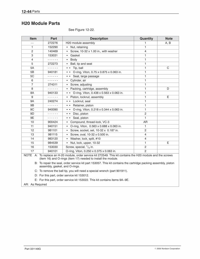
Parts12-44
Part 331149G � 2005 Nordson Corporation
H20 Module Parts See Figure 12-22.
Item Part Description Quantity Note— 272276 H20 module assembly 1 A, B1 152290 � Nut, retaining 12 140469 � Screw, 10-32 x 1.00 in., with washer 43 153031 � Gasket 14 - - - - - - � Body 15 272273 � Ball, tip and seat 1
5A - - - - - - � � Tip, ball 1 C5B 940181 � � O-ring, Viton, 0.75 x 0.875 x 0.063 in. 15C - - - - - - � � Seat, large passage 16 - - - - - - � Cylinder, air 17 274311 � Screw, adjusting 18 - - - - - - � Packing, cartridge, assembly 1 D
8A 940133 � � O-ring, Viton, 0.438 x 0.563 x 0.063 in. 19 - - - - - - � Piston, locknut, assembly 1 E
9A 240274 � � Locknut, seal 19B - - - - - - � � Retainer, piston 19C 940090 � � O-ring, Viton, 0.218 x 0.344 x 0.063 in. 19D - - - - - - � � Disc, piston 29E - - - - - - � � Seal, piston 110 900424 � Compound, thread-lock, VC-3 AR11 940151 � O-ring, Viton, 0.563 x 0.688 x 0.063 in. 112 981101 � Screw, socket, set, 10-32 x 0.187 in. 213 981115 � Screw, oval, 10-32 x 0.500 in. 414 983120 � Washer, lock, split, #10 415 984539 � Nut, lock, upper, 10-32 1 E16 153030 Screw, special, 1/4 in. 217 940101 O-ring, Viton, 0.250 x 0.375 x 0.063 in. 2
NOTE A: To replace an H-20 module, order service kit 272549. This kit contains the H20 module and the screws(item 16) and O-rings (item 17) needed to install the module.
B: To repair the seal, order service kit part 153057. This kit contains the cartridge packing assembly, pistonassembly, gasket, and O-rings.
C: To remove the ball tip, you will need a special wrench (part 901911).
D: For this part, order service kit 153012.
E: For this part, order service kit 153022. This kit contains items 9A−9E.
AR: As Required
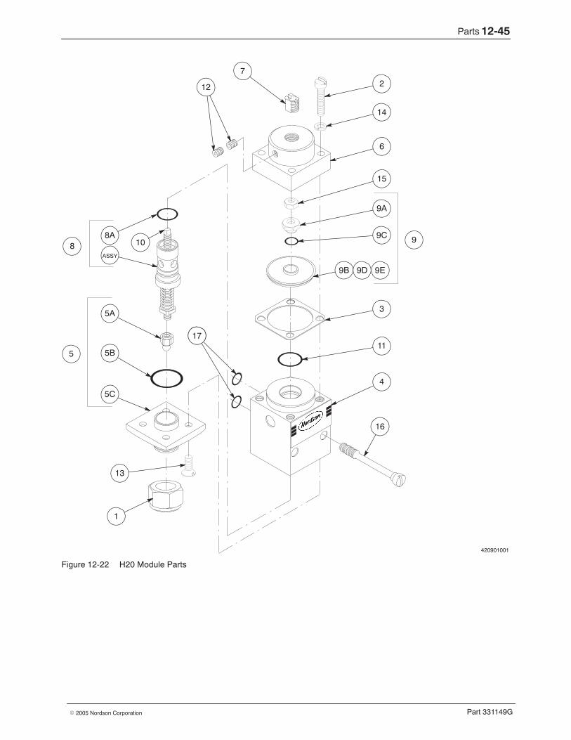
Parts 12-45
Part 331149G� 2005 Nordson Corporation
420901001
7
2
14
6
15
9A
9C
9B
3
11
4
1
5C
5B
5A
8A
16
ASSY
9D
17
12
9E
9
5
8 10
13
Figure 12-22 H20 Module Parts
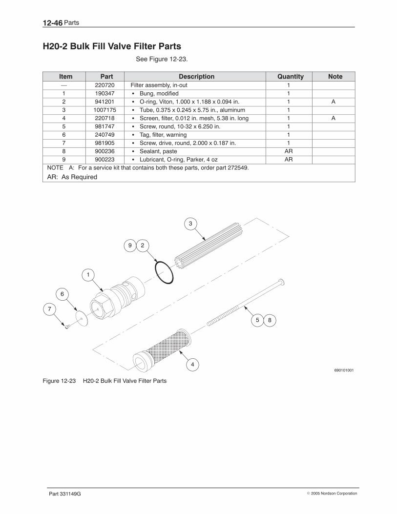
Parts12-46
Part 331149G � 2005 Nordson Corporation
H20-2 Bulk Fill Valve Filter Parts See Figure 12-23.
Item Part Description Quantity Note— 220720 Filter assembly, in-out 11 190347 � Bung, modified 12 941201 � O-ring, Viton, 1.000 x 1.188 x 0.094 in. 1 A3 1007175 � Tube, 0.375 x 0.245 x 5.75 in., aluminum 14 220718 � Screen, filter, 0.012 in. mesh, 5.38 in. long 1 A5 981747 � Screw, round, 10-32 x 6.250 in. 16 240749 � Tag, filter, warning 17 981905 � Screw, drive, round, 2.000 x 0.187 in. 18 900236 � Sealant, paste AR9 900223 � Lubricant, O-ring, Parker, 4 oz AR
NOTE A: For a service kit that contains both these parts, order part 272549.
AR: As Required
690101001
ÏÏÏÏÏÏÏÏÏÏÏÏÏÏÏÏÏÏÏÏ 4
6
7
1
3
5 8
29
Figure 12-23 H20-2 Bulk Fill Valve Filter Parts
Parts 12-47
Part 331149G� 2005 Nordson Corporation
Manifold and Control Valve Parts Lists Your melter may have one to four manifolds. The manifold parts varydepending on whether the manifold is a single-stream or dual-streammanifold, whether it is internally circulating or externally circulating, andwhether it has one, two, or four transducers installed. Table 12-4 providesan overview of all possible manifold assemblies. To determine the manifoldconfiguration of your melter, refer to Explanation of the Melter ConfigurationCode in Section 13, Technical Data.
Table 12-4 Overview of Manifold Assemblies
Manifold Type Type ofCirculation No. of Transducers Manifold Module
Part Number
ManifoldAssembly Part
NumberBlank None None 180420 None
Single-stream Internal 1 (post-filter) 187865 238574g
2 (1 pre- and 1 post-filter) 187863 238573
External 1 (post-filter) 187861 238572
2 (1 pre- and 1 post-filter) 187859 238579
Dual-stream Internal 2 (post-filter) 187857 238578
4 (2 pre- and 2 post-filter) 187855 238577
External 2 (post-filter) 187853 238576
4 (2 pre- and 2 post-filter) 187851 238575
NOTE A: The manifold module includes the wiring harness; the manifold assembly does not.
All manifold assemblies include the components shown in Table 12-5.
Table 12-5 Overview of Common Manifold Components
Component Part NumberManifold filter 234856
Pressure relief valve 234345
Pressure transducer (from 1−4) 188031
All manifolds also include one of the control valves shown in Table 12-6.Control valves, along with mounting hardware, are not included in themanifold assembly and must be ordered separately.
Table 12-6 Overview of Manifold Control Valves
Type of Control Valve Part Number (includesmounting hardware)
Pressure control valve 187940
Flow control valve 187941
Air-operated pressure control valve 757983

Parts12-48
Part 331149G � 2005 Nordson Corporation
Manifold and Control Valve Interface Parts See Figure 12-24. This parts list and illustration show how the manifold andcontrol valves interface. Manifolds have one of three types of control valve:pressure control, flow control, or air-operated control. The quantities varydepending on the number of manifolds present on your melter. To determinethe manifold and control valve configuration of your melter, refer toExplanation of the Melter Configuration Code in Section 13, Technical Data.
Item Part Description Quantity Note— - - - - - - Module, manifold — A1 - - - - - - Manifold assembly 1−4 B2 187940 Pressure control valve and mounting hardware
(items 4−7)1−4 C
187941 Flow control valve and mounting hardware(items 4−7)
1−4 D
3 757983 Air-operated pressure control valve and mountinghardware (items 4−7)
1−4 E
4 328174 Retainer, control valve 1−45 982478 Screw, socket, M10 x 30 1−46 983405 Washer, lock, split, M10 1−47 985232 Pin, roll, 4 x 8 mm 2−88 1004726 Kit, pneumatic assembly, 4 solenoid valves 1 F
1004727 Kit, pneumatic assembly, 8 solenoid valves 1 FNS 226584 Harness, manifold wiring 1−4 G
NOTE A: The manifold module part number varies depending on the configuration of the melter. Refer toTable 12-4.
B: Refer to Blank Manifold Parts, Single-Stream Manifold Parts, or Dual-Stream Manifold Parts later in thissection for a detailed parts list and illustration.
C: Refer to Pressure Control Valve Parts later in this section for a detailed parts list and illustration.
D: Refer to Flow Control Valve Parts later in this section for a detailed parts list and illustration.
E: Refer to Air-Operated Pressure Control Valve Parts later in this section for a detailed parts list andillustration.
F: The pneumatic assembly is present only on melters with air-operated pressure control valves. Refer toPneumatic Assembly Parts later in this section for a detailed parts list and illustration.
G: The wiring diagram for this harness is included on the electrical schematics located inside the electricalenclosure.
NS: Not Shown
Parts 12-49
Part 331149G� 2005 Nordson Corporation
B
A
1
3
2
4 4
5
7
656
2
3
Detail ADetail B
8
Figure 12-24 Manifold and control valve interface parts
Parts12-50
Part 331149G � 2005 Nordson Corporation
Blank Manifold Parts See Figure 12-25.
Item Part Description Quantity Note— 180420 Module, manifold, blank —1 973455 � Plug, O-ring, straight thread, M33 x 2 12 900344 � Lubricant, Never-Seez, 8 oz can AR
AR: As Required
1 2
Figure 12-25 Blank manifold parts (melter with one single-stream and one blank manifold per reservoir shown)
Parts 12-51
Part 331149G� 2005 Nordson Corporation
Single-Stream Manifold Parts See Figure 12-26.
Item Part Description Quantity Note— - - - - - - Module, manifold, single-stream — A— - - - - - - � Manifold assembly, single-stream 1 A1 238562 � � Manifold, single-stream, common assembly 12 234356 � � � Filter assembly, manifold 1 B3 234345 � � � Valve assembly, pressure relief 1 C4 — � � � Item no. not used —5 276621 � � � Tip, drain valve 16 900037 � � � Ball, 440 stainless steel, 0.250 in. 17 986239 � � � Retaining ring, spiral 18 973455 � � � Plug, O-ring, straight-thread, M33 x 2.0 19 973454 � � � Plug, O-ring, straight-thread, M10 x 1 14
10−14 — � � � Item nos. not used —15 973459 � � � Plug, O-ring, straight-thread, M22 x 1.5 2 D16 180386 � � � Plate, heater 117 157946 � � � Retainer, heater, 0.312 x 0.937 x 0.050 in.,
two-bend1
18 982059 � � � Screw, socket, M4 x 8 119 142278 � � � Adapter, bayonet, 1/8 NPT 120 981830 � � � Screw, socket, M6 x 25 621 249668 � � � Retainer, filter 122 238569 � � � Insert assembly, threaded, with O-rings
(items 40 and 41)1
23 982176 � � � Screw, socket, M6 x 16 224 302547 � � � Bracket, left-hand, manifold mounting 125 302548 � � � Bracket, right-hand, manifold mounting 126 982128 � � � Screw, hex, machine, M6 x 10 427 985412 � � � Pin, locating, 0.250 x 1.000 in. 228 1004370 � � Pump seal bolt and O-rings 129 225331 � � Spring, washer, 10.2 ID x 20 OD mm 230 188031 � � Pressure transducer assembly, with swivel 1−2 E31 945117 � � O-ring, Viton, 56.0 x 5.3 mm 1
NOTE A: The manifold module and assembly part numbers vary depending on the configuration of the melter. Referto Table 12-4 to determine the appropriate module or assembly part number for your melter; then use thatpart number if you need to order a complete replacement manifold.
B: Refer to Manifold Filter Parts later in this section for a detailed parts list and illustration.
C: Refer to Pressure Relief Valve Parts later in this section for a detailed parts list and illustration.
D: For each installed hose, this O-ring plug is removed and replaced with a hose connector.
E: Refer to Pressure Transducer Parts later in this section for a detailed parts list and illustration.Figure 12-26 shows a manifold with two pressure transducers. In manifolds with only one transducer, aplug (part 973458) is installed in the empty pre-filter transducer port.
AR: As Required
Continued on next page
Parts12-52
Part 331149G � 2005 Nordson Corporation
Single-Stream Manifold Parts (contd)
Item Part Description Quantity Note32−33 — � � Item nos. not used —
34 973480 � � Plug, O-ring, straight-thread, M14 x 1.5,internal circulation
1 F
35 180527 � � Plug assembly, external circulation 1 G36 982023 � � Screw, socket, M3 x 8 237 224841 � � Tag, circulation, internal/external 138 237206 � � RTD, platinum, 90-degree, bayonet, with
connector1
39 237209 � � Thermoswitch, with ferrules 1NS 973458 � � Plug, O-ring, straight thread, M16 x 1.5 1 HNS 900344 � � Lubricant, Never-Seez, 8 oz can AR INS 900223 � � Lubricant, O-ring, Parker, 4 oz AR J40 940293 O-ring, Viton, 1.500 x 1.625 x 0.063 in. 1 K41 940303 O-ring, Viton, 1.625 x 1.750 x 0.063 in. 1 K
F: This plug is installed in internally circulating manifolds. To change the type of circulation from internal toexternal, remove this plug and install the external circulation plug (part 180527). Refer to Changing theCirculation in a Manifold in Section 3, Installation.
G: This plug is installed in externally circulating manifolds. To change the type of circulation from external tointernal, remove this plug and install the internal circulation plug (part 973480). Refer to Changing theCirculation in a Manifold in Section 3, Installation.
H: If the manifold has only one pressure transducer, this plug is installed in the empty pre-filter transducerport.
I: Apply Never-Seez lubricant to all threads.
J: Apply O-ring lubricant to all O-rings.
K: This O-ring is part of the insert assembly, part 238 569 (item 22).
AR: As Required
NS: Not Shown
Parts 12-53
Part 331149G� 2005 Nordson Corporation
410101012
36
9
9
28
38
19
20
22
18
17
39
168
1
9
30
9
29
31
15
9
37
5
6
2
2123
37
27 24
26
25 26 27
35
34
Back view
30
4041
Figure 12-26 Single-stream manifold parts

Parts12-54
Part 331149G � 2005 Nordson Corporation
This page intentionally left blank.
Parts 12-55
Part 331149G� 2005 Nordson Corporation
Dual-Stream Manifold Parts See Figure 12-27.
Item Part Description Quantity Note— - - - - - - Module, manifold, dual-stream — A— - - - - - - � Manifold assembly, dual-stream 1 A1 238563 � � Manifold, dual-stream, common assembly 12 234356 � � � Filter assembly, manifold 2 B3 234345 � � � Valve assembly, pressure relief 2 C4 — � � � Item no. not used —5 276621 � � � Tip, drain valve 26 900037 � � � Ball, 440 stainless steel, 0.250 in. 27 986239 � � � Retaining ring, spiral 28 973455 � � � Plug, O-ring, straight-thread, M33 x 2.0 19 973454 � � � Plug, O-ring, straight-thread, M10 x 1 18
10−14 — � � � Item nos. not used —15 973459 � � � Plug, O-ring, straight-thread, M22 x 1.5 4 D16 180386 � � � Plate, heater 117 157946 � � � Retainer, heater, 0.312 x 0.937 x 0.050 in.,
two-bend1
18 982059 � � � Screw, socket, M4 x 8 119 142278 � � � Adapter, bayonet, 1/8 NPT 120 981830 � � � Screw, socket, M6 x 25 621 249668 � � � Retainer, filter 222 238569 � � � Insert assembly, threaded, with O-rings
(items 40 and 41)2
23 982176 � � � Screw, socket, M6 x 16 424 302547 � � � Bracket, left-hand, manifold mounting 125 302548 � � � Bracket, right-hand, manifold mounting 126 982128 � � � Screw, hex, machine, M6 x 10 427 985412 � � � Pin, locating, 0.250 x 1.000 in. 228 1004370 � � Assembly, pump seal bolt and O-rings 129 225331 � � Spring, washer, 10.2 ID x 20 OD mm 230 188031 � � Pressure transducer assembly, with swivel 2−4 E
NOTE A: The manifold module and assembly part numbers vary depending on the configuration of the melter. Referto Table 12-4 to determine the appropriate module or assembly part number for your melter; then use thatpart number if you need to order a complete replacement manifold.
B: Refer to the next parts list, Manifold Filter Parts, for a detailed parts list and illustration.
C: Refer to Pressure Relief Valve Parts later in this section for a detailed parts list and illustration.
D: For each installed hose, this O-ring plug is removed and replaced with a hose connector.
E: Refer to Pressure Transducer Parts later in this section for a detailed parts list and illustration.Figure 12-27 shows a manifold with four pressure transducers. In manifolds with fewer transducers, aplug (part 973458) is installed in the empty transducer ports.
AR: As Required
Continued on next page
Parts12-56
Part 331149G � 2005 Nordson Corporation
Dual-Stream Manifold Parts (contd)
Item Part Description Quantity Note31 945117 � � O-ring, Viton, 56.0 x 5.3 mm 1
32−33 — � � Item nos. not used —34 973480 � � Plug, O-ring, straight-thread, M14 x 1.5 mm,
internal circulation2 F
35 180527 � � Plug assembly, external circulation 2 G36 982023 � � Screw, socket, M3 x 8 237 224841 � � Tag, circulation, internal/external 138 237206 � � RTD, platinum, 90-degree, bayonet, with
connector1
39 237209 � � Thermoswitch with ferrules assembly 1NS 973458 � � Plug, O-ring, straight thread, M16 x 1.5 2 HNS 900344 � � Lubricant, Never-Seez, 8 oz can AR INS 900223 � � Lubricant, O-ring, Parker, 4 oz AR J40 940293 O-ring, Viton, 1.500 x 1.625 x 0.063 in. 1 K41 940303 O-ring, Viton, 1.625 x 1.750 x 0.063 in. 1 K
F: This plug is installed in internally circulating manifolds. To change the type of circulation from internal toexternal, remove this plug and install the external circulation plug (part 180527). Refer to Changing theCirculation in a Manifold in Section 3, Installation.
G: This plug is installed in externally circulating manifolds. To change the type of circulation from external tointernal, remove this plug and install the internal circulation plug (part 973480). Refer to Changing theCirculation in a Manifold in Section 3, Installation.
H: If the manifold has fewer than four pressure transducers, this plug is installed in the empty transducerports.
I: Apply O-ring lubricant to all O-rings.
J: Apply anti-seize lubricant to all threads.
K: This O-ring is part of the insert assembly, part 238569 (item 22).
AR: As Required
NS: Not Shown
Parts 12-57
Part 331149G� 2005 Nordson Corporation
410101013
36
30
37
27
24
26
31
15
9
1
9
25
816
18
17
39
15
28
34
9
22
23
2
3
29
7
5
6
19
38
35
21 23
2
20
21
30
Back view
26 27
4041
Figure 12-27 Dual-stream manifold parts
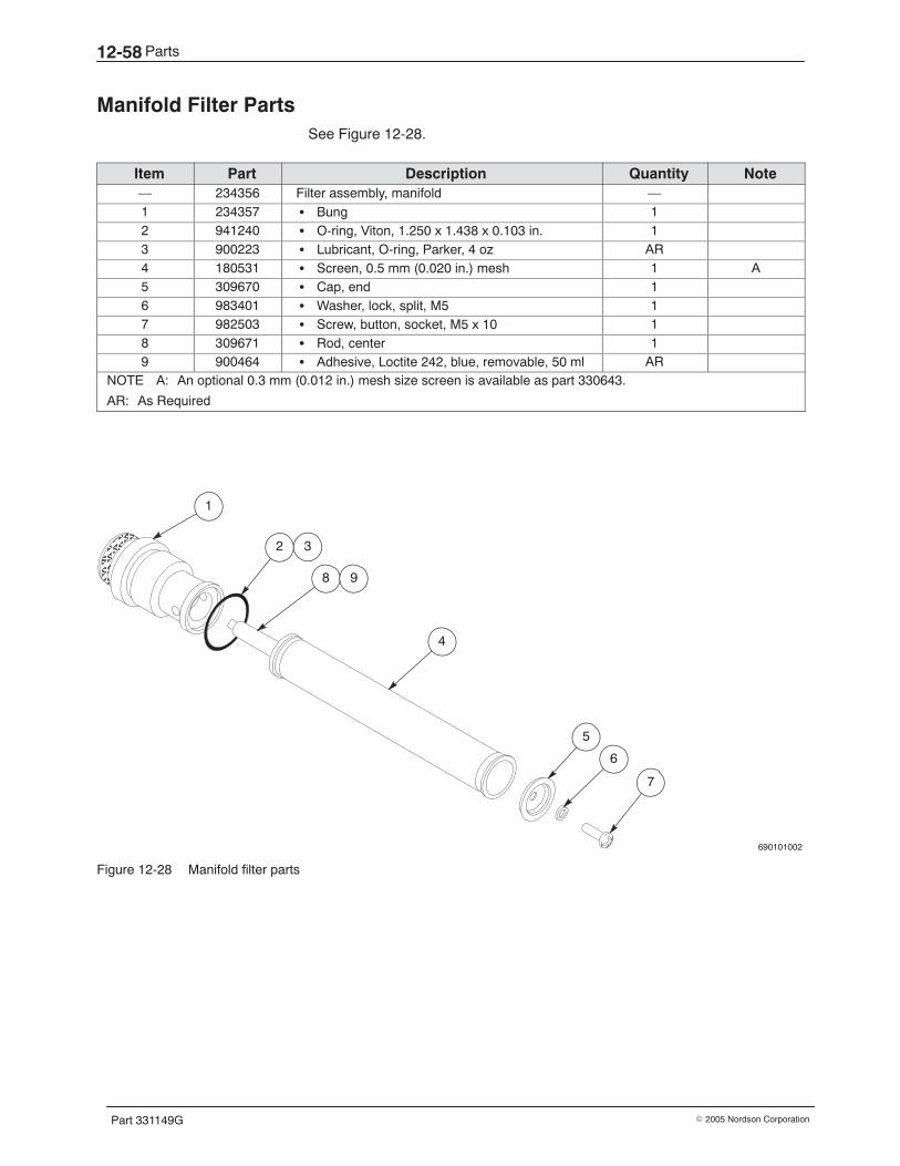
Parts12-58
Part 331149G � 2005 Nordson Corporation
Manifold Filter Parts See Figure 12-28.
Item Part Description Quantity Note— 234356 Filter assembly, manifold —1 234357 � Bung 12 941240 � O-ring, Viton, 1.250 x 1.438 x 0.103 in. 13 900223 � Lubricant, O-ring, Parker, 4 oz AR4 180531 � Screen, 0.5 mm (0.020 in.) mesh 1 A5 309670 � Cap, end 16 983401 � Washer, lock, split, M5 17 982503 � Screw, button, socket, M5 x 10 18 309671 � Rod, center 19 900464 � Adhesive, Loctite 242, blue, removable, 50 ml AR
NOTE A: An optional 0.3 mm (0.012 in.) mesh size screen is available as part 330643.
AR: As Required
690101002
ÂÂÂÂÂÂÂÂÂ
1
2
8
4
5
6
7
9
3
Figure 12-28 Manifold filter parts

Parts 12-59
Part 331149G� 2005 Nordson Corporation
This page intentionally left blank.
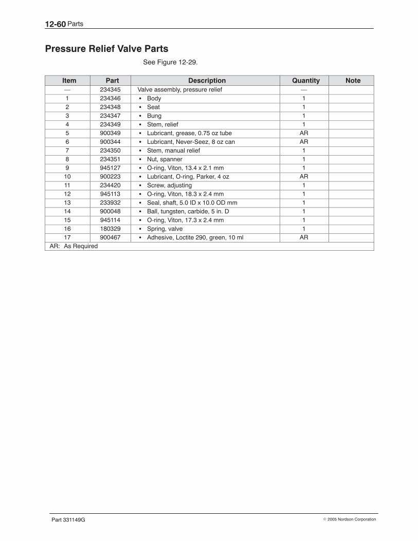
Parts12-60
Part 331149G � 2005 Nordson Corporation
Pressure Relief Valve Parts See Figure 12-29.
Item Part Description Quantity Note— 234345 Valve assembly, pressure relief —1 234346 � Body 12 234348 � Seat 13 234347 � Bung 14 234349 � Stem, relief 15 900349 � Lubricant, grease, 0.75 oz tube AR6 900344 � Lubricant, Never-Seez, 8 oz can AR7 234350 � Stem, manual relief 18 234351 � Nut, spanner 19 945127 � O-ring, Viton, 13.4 x 2.1 mm 110 900223 � Lubricant, O-ring, Parker, 4 oz AR11 234420 � Screw, adjusting 112 945113 � O-ring, Viton, 18.3 x 2.4 mm 113 233932 � Seal, shaft, 5.0 ID x 10.0 OD mm 114 900048 � Ball, tungsten, carbide, 5 in. D 115 945114 � O-ring, Viton, 17.3 x 2.4 mm 116 180329 � Spring, valve 117 900467 � Adhesive, Loctite 290, green, 10 ml AR
AR: As Required
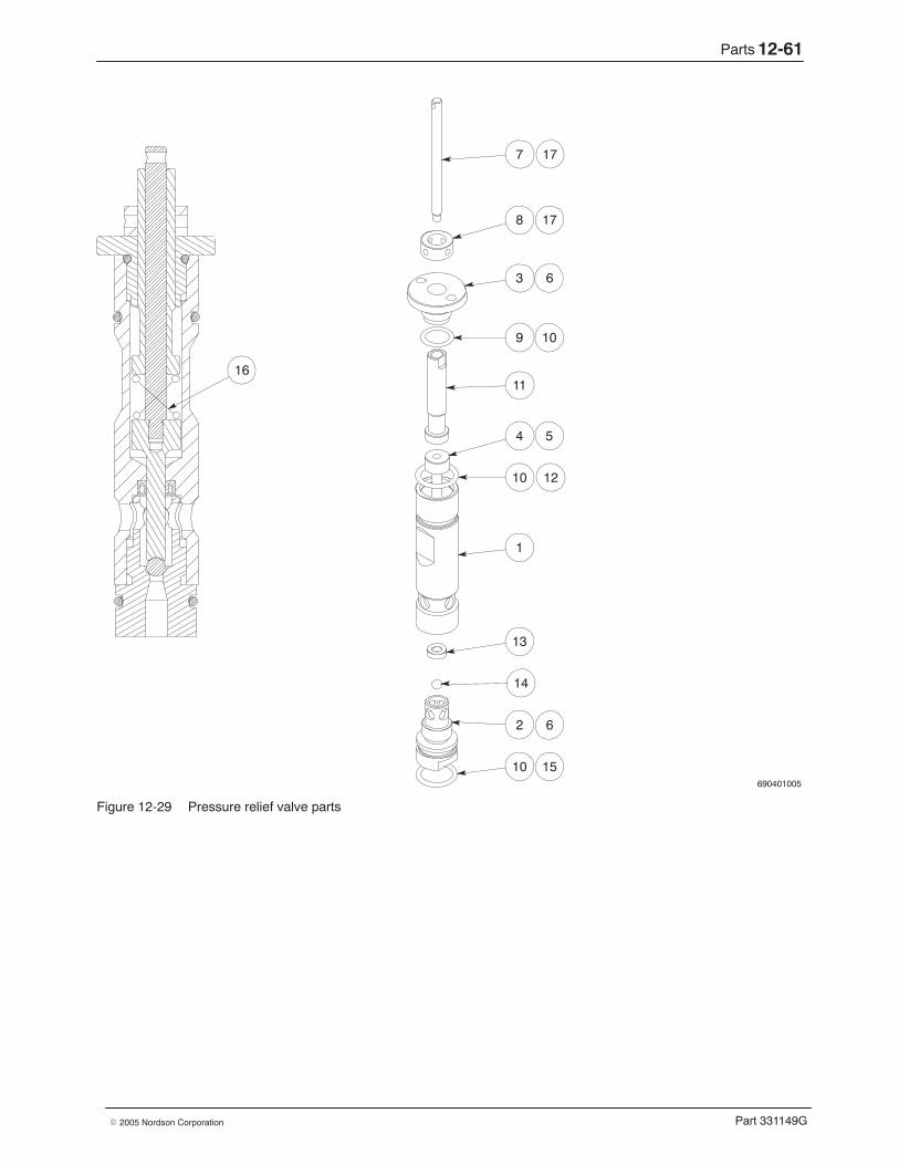
Parts 12-61
Part 331149G� 2005 Nordson Corporation
690401005
7
8
3
9
11
4
10
1
13
14
2
10
17
17
6
10
5
12
6
15
16
Figure 12-29 Pressure relief valve parts
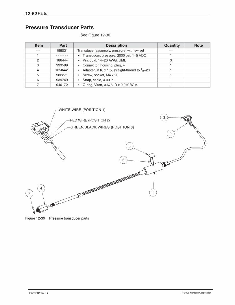
Parts12-62
Part 331149G � 2005 Nordson Corporation
Pressure Transducer Parts See Figure 12-30.
Item Part Description Quantity Note— 188031 Transducer assembly, pressure, with swivel —1 - - - - - - � Transducer, pressure, 2000 psi, 1−5 VDC 12 186444 � Pin, gold, 14−20 AWG, UML 33 933599 � Connector, housing, plug, 4 14 1050441 � Adapter, M16 x 1.5, straight-thread to 1/2-20 15 982271 � Screw, socket, M4 x 20 16 939749 � Strap, cable, 4.00 in. 17 940172 � O-ring, Viton, 0.676 ID x 0.070 W in. 1
3
2
1
5
GREEN/BLACK WIRES (POSITION 3)
RED WIRE (POSITION 2)
WHITE WIRE (POSITION 1)
6
47
Figure 12-30 Pressure transducer parts

Parts 12-63
Part 331149G� 2005 Nordson Corporation
This page intentionally left blank.
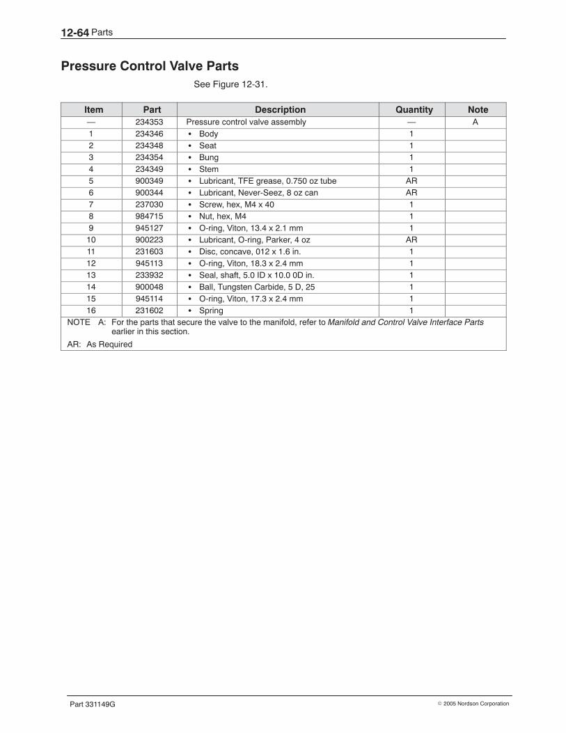
Parts12-64
Part 331149G � 2005 Nordson Corporation
Pressure Control Valve Parts See Figure 12-31.
Item Part Description Quantity Note— 234353 Pressure control valve assembly — A1 234346 � Body 12 234348 � Seat 13 234354 � Bung 14 234349 � Stem 15 900349 � Lubricant, TFE grease, 0.750 oz tube AR6 900344 � Lubricant, Never-Seez, 8 oz can AR7 237030 � Screw, hex, M4 x 40 18 984715 � Nut, hex, M4 19 945127 � O-ring, Viton, 13.4 x 2.1 mm 110 900223 � Lubricant, O-ring, Parker, 4 oz AR11 231603 � Disc, concave, 012 x 1.6 in. 112 945113 � O-ring, Viton, 18.3 x 2.4 mm 113 233932 � Seal, shaft, 5.0 ID x 10.0 0D in. 114 900048 � Ball, Tungsten Carbide, 5 D, 25 115 945114 � O-ring, Viton, 17.3 x 2.4 mm 116 231602 � Spring 1
NOTE A: For the parts that secure the valve to the manifold, refer to Manifold and Control Valve Interface Partsearlier in this section.
AR: As Required
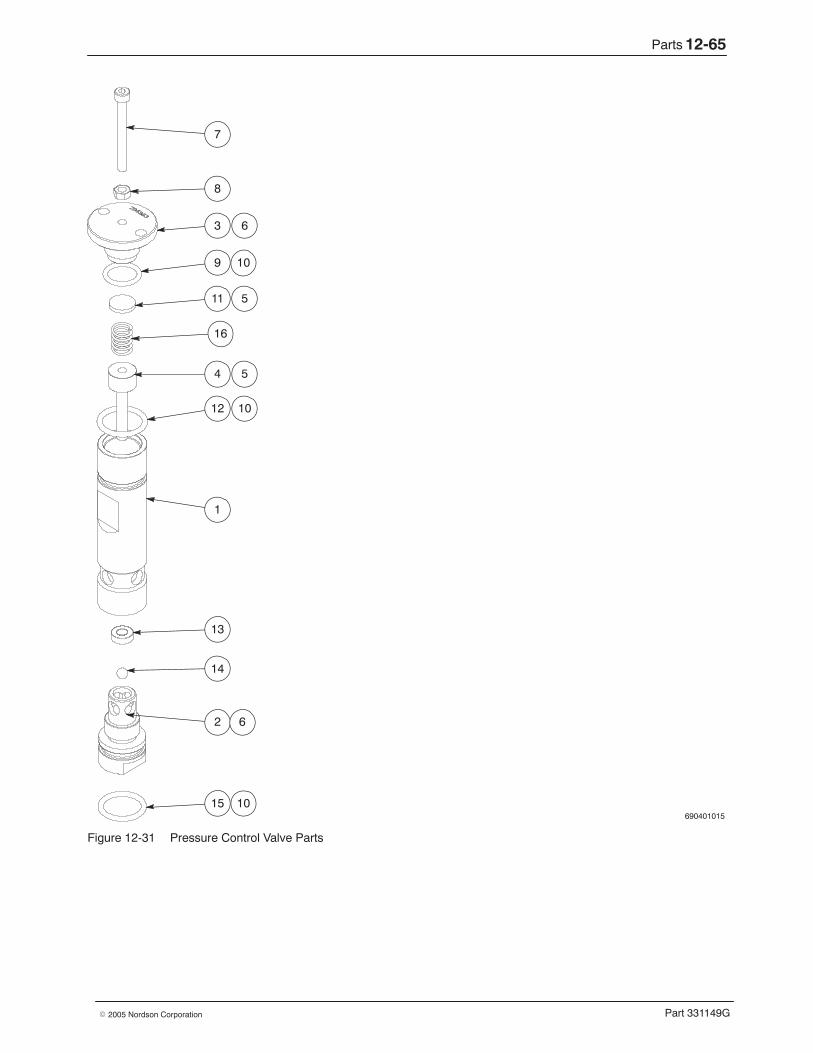
Parts 12-65
Part 331149G� 2005 Nordson Corporation
690401015
7
8
3
9
11
4
12
1
13
14
2
15
6
6
10
10
5
5
10
16
Figure 12-31 Pressure Control Valve Parts
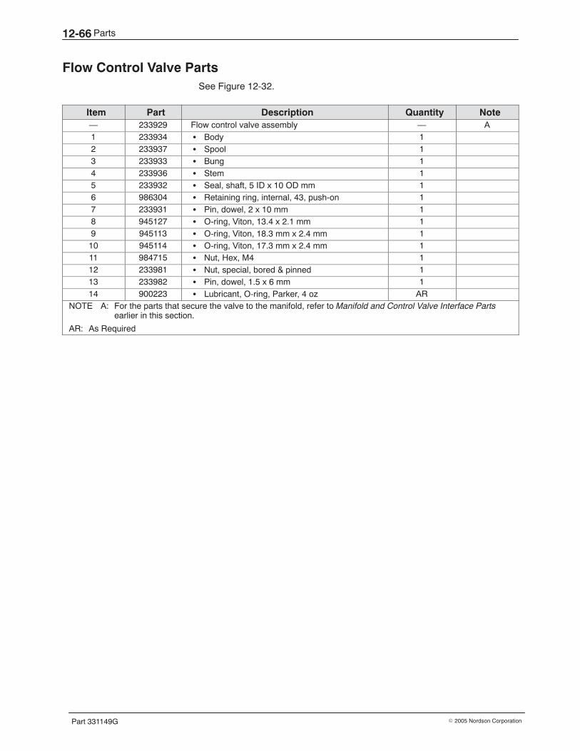
Parts12-66
Part 331149G � 2005 Nordson Corporation
Flow Control Valve Parts See Figure 12-32.
Item Part Description Quantity Note— 233929 Flow control valve assembly — A1 233934 � Body 12 233937 � Spool 13 233933 � Bung 14 233936 � Stem 15 233932 � Seal, shaft, 5 ID x 10 OD mm 16 986304 � Retaining ring, internal, 43, push-on 17 233931 � Pin, dowel, 2 x 10 mm 18 945127 � O-ring, Viton, 13.4 x 2.1 mm 19 945113 � O-ring, Viton, 18.3 mm x 2.4 mm 110 945114 � O-ring, Viton, 17.3 mm x 2.4 mm 111 984715 � Nut, Hex, M4 112 233981 � Nut, special, bored & pinned 113 233982 � Pin, dowel, 1.5 x 6 mm 114 900223 � Lubricant, O-ring, Parker, 4 oz AR
NOTE A: For the parts that secure the valve to the manifold, refer to Manifold and Control Valve Interface Partsearlier in this section.
AR: As Required
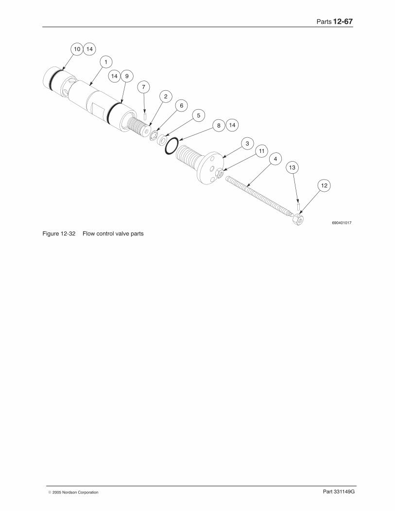
Parts 12-67
Part 331149G� 2005 Nordson Corporation
690401017
1
7
2
6
5
3
4
13
12
8
9
10 14
14
14
11
Figure 12-32 Flow control valve parts
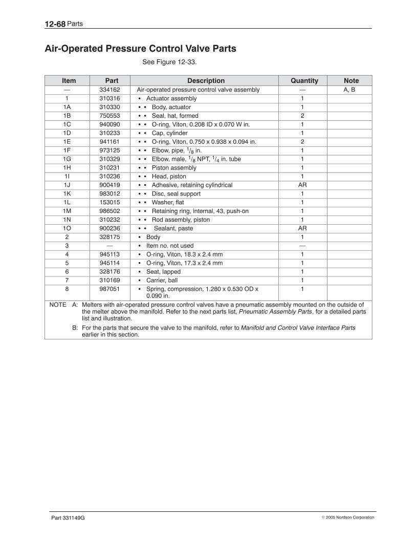
Parts12-68
Part 331149G � 2005 Nordson Corporation
Air-Operated Pressure Control Valve Parts See Figure 12-33.
Item Part Description Quantity Note— 334162 Air-operated pressure control valve assembly — A, B1 310316 � Actuator assembly 1
1A 310330 � � Body, actuator 11B 750553 � � Seal, hat, formed 21C 940090 � � O-ring, Viton, 0.208 ID x 0.070 W in. 11D 310233 � � Cap, cylinder 11E 941161 � � O-ring, Viton, 0.750 x 0.938 x 0.094 in. 21F 973125 � � Elbow, pipe, 1/8 in. 11G 310329 � � Elbow, male, 1/8 NPT, 1/4 in. tube 11H 310231 � � Piston assembly 11I 310236 � � Head, piston 11J 900419 � � Adhesive, retaining cylindrical AR1K 983012 � � Disc, seal support 11L 153015 � � Washer, flat 11M 986502 � � Retaining ring, internal, 43, push-on 11N 310232 � � Rod assembly, piston 11O 900236 � � Sealant, paste AR2 328175 � Body 13 — � Item no. not used —4 945113 � O-ring, Viton, 18.3 x 2.4 mm 15 945114 � O-ring, Viton, 17.3 x 2.4 mm 16 328176 � Seat, lapped 17 310169 � Carrier, ball 18 987051 � Spring, compression, 1.280 x 0.530 OD x
0.090 in.1
NOTE A: Melters with air-operated pressure control valves have a pneumatic assembly mounted on the outside ofthe melter above the manifold. Refer to the next parts list, Pneumatic Assembly Parts, for a detailed partslist and illustration.
B: For the parts that secure the valve to the manifold, refer to Manifold and Control Valve Interface Partsearlier in this section.
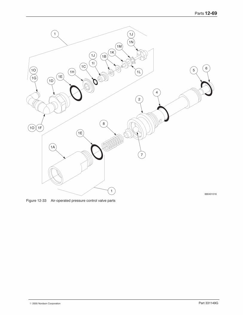
Parts 12-69
Part 331149G� 2005 Nordson Corporation
690401016
1N1M
1K1B
1I1C
1H1E
1D1G
1F
5
2
4
8
1E
1A
7
6
1
1
1L
1J
1J
1O
1O
Figure 12-33 Air-operated pressure control valve parts
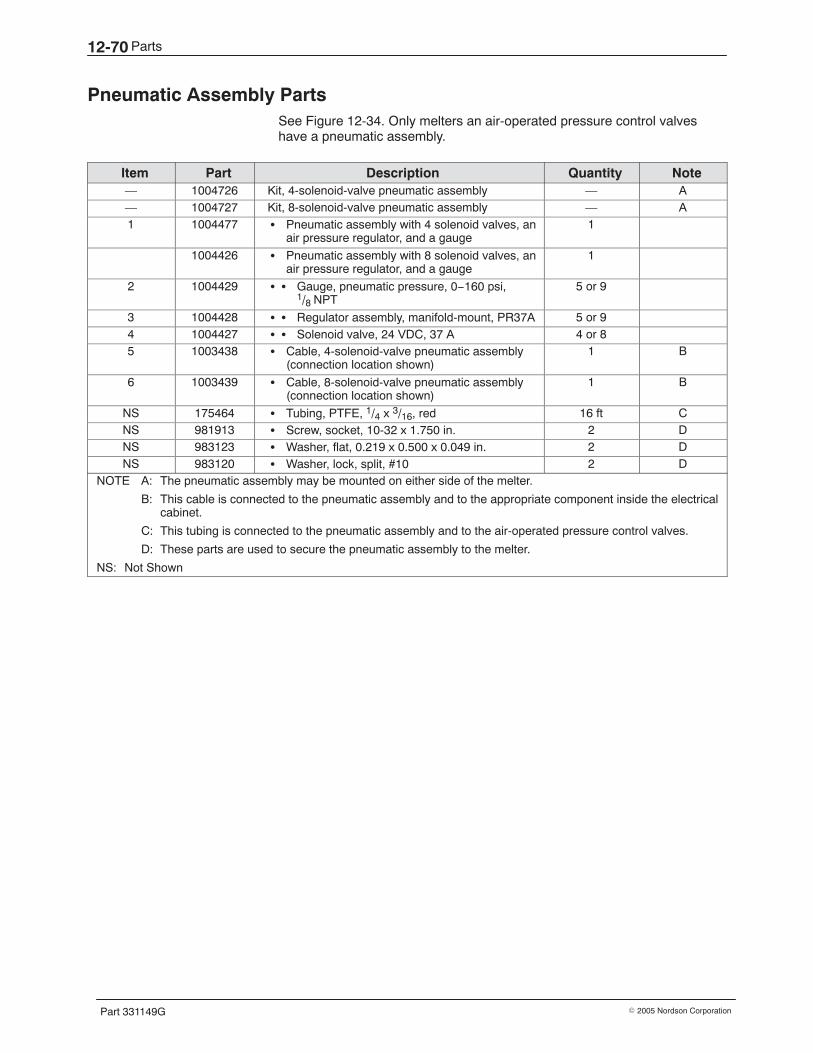
Parts12-70
Part 331149G � 2005 Nordson Corporation
Pneumatic Assembly Parts See Figure 12-34. Only melters an air-operated pressure control valveshave a pneumatic assembly.
Item Part Description Quantity Note— 1004726 Kit, 4-solenoid-valve pneumatic assembly — A— 1004727 Kit, 8-solenoid-valve pneumatic assembly — A1 1004477 � Pneumatic assembly with 4 solenoid valves, an
air pressure regulator, and a gauge1
1004426 � Pneumatic assembly with 8 solenoid valves, anair pressure regulator, and a gauge
1
2 1004429 � � Gauge, pneumatic pressure, 0−160 psi,1/8 NPT
5 or 9
3 1004428 � � Regulator assembly, manifold-mount, PR37A 5 or 94 1004427 � � Solenoid valve, 24 VDC, 37 A 4 or 85 1003438 � Cable, 4-solenoid-valve pneumatic assembly
(connection location shown)1 B
6 1003439 � Cable, 8-solenoid-valve pneumatic assembly(connection location shown)
1 B
NS 175464 � Tubing, PTFE, 1/4 x 3/16, red 16 ft CNS 981913 � Screw, socket, 10-32 x 1.750 in. 2 DNS 983123 � Washer, flat, 0.219 x 0.500 x 0.049 in. 2 DNS 983120 � Washer, lock, split, #10 2 D
NOTE A: The pneumatic assembly may be mounted on either side of the melter.
B: This cable is connected to the pneumatic assembly and to the appropriate component inside the electricalcabinet.
C: This tubing is connected to the pneumatic assembly and to the air-operated pressure control valves.
D: These parts are used to secure the pneumatic assembly to the melter.
NS: Not Shown
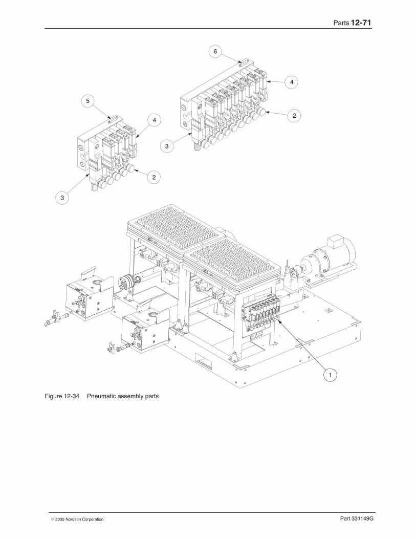
Parts 12-71
Part 331149G� 2005 Nordson Corporation
1
3
6
4
2
5
3
4
2
Figure 12-34 Pneumatic assembly parts

Parts12-72
Part 331149G � 2005 Nordson Corporation
This page intentionally left blank.
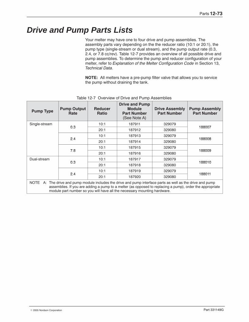
Parts 12-73
Part 331149G� 2005 Nordson Corporation
Drive and Pump Parts Lists Your melter may have one to four drive and pump assemblies. Theassembly parts vary depending on the the reducer ratio (10:1 or 20:1), thepump type (single-stream or dual stream), and the pump output rate (0.3,2.4, or 7.8 cc/rev). Table 12-7 provides an overview of all possible drive andpump assemblies. To determine the pump and reducer configuration of yourmelter, refer to Explanation of the Melter Configuration Code in Section 13,Technical Data.
NOTE: All melters have a pre-pump filter valve that allows you to servicethe pump without draining the tank.
Table 12-7 Overview of Drive and Pump Assemblies
Pump Type Pump OutputRate
ReducerRatio
Drive and PumpModule
Part Number(See Note A)
Drive AssemblyPart Number
Pump AssemblyPart Number
Single-stream0 3
10:1 187911 329079188007
g0.3
20:1 187912 329080188007
2 410:1 187913 329079
1880082.420:1 187914 329080
188008
7 810:1 187915 329079
1880097.820:1 187916 329080
188009
Dual-stream0 3
10:1 187917 3290791880100.3
20:1 187918 329080188010
2 410:1 187919 329079
1880112.420:1 187920 329080
188011
NOTE A: The drive and pump module includes the drive and pump interface parts as well as the drive and pumpassemblies. If you are adding a pump to a melter (as opposed to replacing a pump), order the appropriatemodule part number so you will have all the necessary mounting hardware.
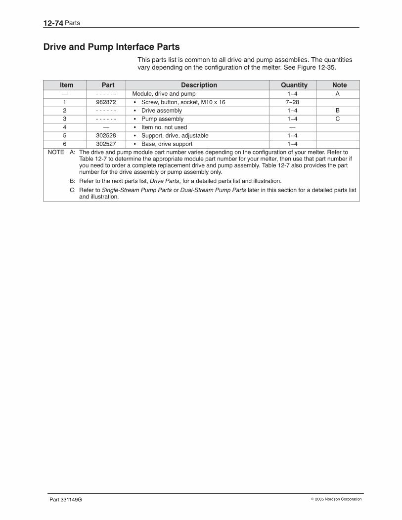
Parts12-74
Part 331149G � 2005 Nordson Corporation
Drive and Pump Interface Parts This parts list is common to all drive and pump assemblies. The quantitiesvary depending on the configuration of the melter. See Figure 12-35.
Item Part Description Quantity Note— - - - - - - Module, drive and pump 1−4 A1 982872 � Screw, button, socket, M10 x 16 7−282 - - - - - - � Drive assembly 1−4 B3 - - - - - - � Pump assembly 1−4 C4 — � Item no. not used —5 302528 � Support, drive, adjustable 1−46 302527 � Base, drive support 1−4
NOTE A: The drive and pump module part number varies depending on the configuration of your melter. Refer toTable 12-7 to determine the appropriate module part number for your melter, then use that part number ifyou need to order a complete replacement drive and pump assembly. Table 12-7 also provides the partnumber for the drive assembly or pump assembly only.
B: Refer to the next parts list, Drive Parts, for a detailed parts list and illustration.
C: Refer to Single-Stream Pump Parts or Dual-Stream Pump Parts later in this section for a detailed parts listand illustration.
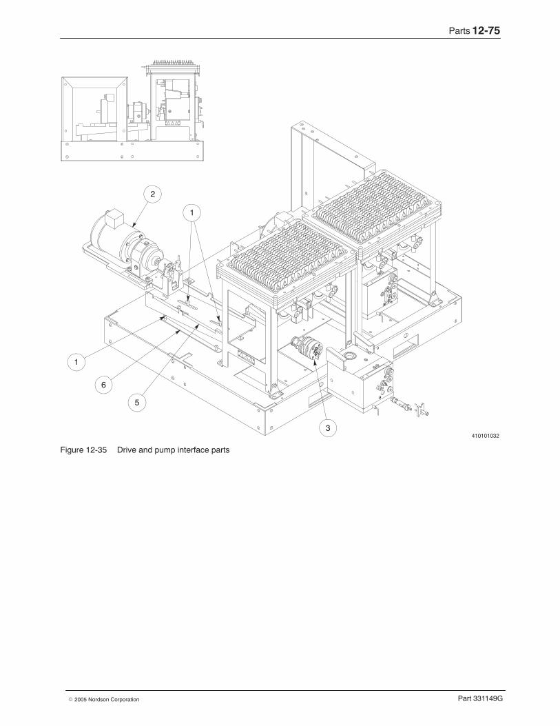
Parts 12-75
Part 331149G� 2005 Nordson Corporation
410101032
1
2
1
6
5
3
Figure 12-35 Drive and pump interface parts
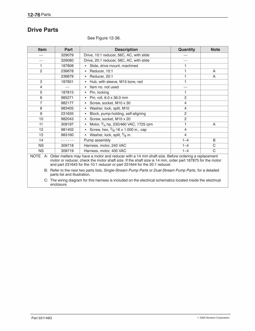
Parts12-76
Part 331149G � 2005 Nordson Corporation
Drive Parts See Figure 12-36.
Item Part Description Quantity Note— 329079 Drive, 10:1 reducer, 56C, AC, with slide —— 329080 Drive, 20:1 reducer, 56C, AC, with slide —1 187808 � Slide, drive mount, machined 12 236678 � Reducer, 10:1 1 A
236679 � Reducer, 20:1 1 A3 187801 � Hub, with sleeve, M15 bore, red 14 — � Item no. not used —5 187815 � Pin, locking 16 985271 � Pin, roll, 6.0 x 36.0 mm 27 982177 � Screw, socket, M10 x 30 48 983405 � Washer, lock, split, M10 49 231635 � Block, pump-holding, self-aligning 210 982043 � Screw, socket, M10 x 20 211 309197 � Motor, 3/4 hp, 230/460 VAC, 1725 rpm 1 A12 981402 � Screw, hex, 3/8-16 x 1.000 in., cap 413 983160 � Washer, lock, split, 3/8 in. 414 - - - - - - Pump assembly 1−4 BNS 309718 Harness, motor, 240 VAC 1−4 CNS 309719 Harness, motor, 400 VAC 1−4 C
NOTE A: Older melters may have a motor and reducer with a 14 mm shaft size. Before ordering a replacementmotor or reducer, check the motor shaft size. If the shaft size is 14 mm, order part 187875 for the motorand part 231643 for the 10:1 reducer or part 231644 for the 20:1 reducer.
B: Refer to the next two parts lists, Single-Stream Pump Parts or Dual-Stream Pump Parts, for a detailedparts list and illustration.
C: The wiring diagram for this harness is included on the electrical schematics located inside the electricalenclosure.
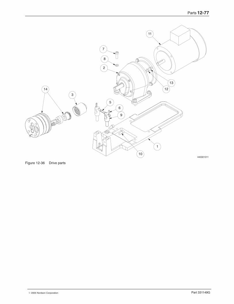
Parts 12-77
Part 331149G� 2005 Nordson Corporation
440301011
11
7
8
2
3
13
12
5
6
9
10
1
14
Figure 12-36 Drive parts
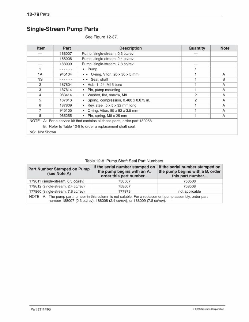
Parts12-78
Part 331149G � 2005 Nordson Corporation
Single-Stream Pump Parts See Figure 12-37.
Item Part Description Quantity Note— 188007 Pump, single-stream, 0.3 cc/rev —— 188008 Pump, single-stream, 2.4 cc/rev —— 188009 Pump, single-stream, 7.8 cc/rev —1 - - - - - - � Pump 1
1A 945104 � � O-ring, Viton, 20 x 30 x 5 mm 1 ANS - - - - - - � � Seal, shaft 1 B2 187804 � Hub, 1−24, M15 bore 1 A3 187814 � Pin, pump mounting 1 A4 983414 � Washer, flat, narrow, M8 2 A5 187813 � Spring, compression, 0.480 x 0.875 in. 2 A6 187809 � Key, steel, 5 x 5 x 32 mm long 1 A7 945105 � O-ring, Viton, 85 x 92 x 3.5 mm 1 A8 985255 � Pin, spring, M8 x 25 mm 1 A
NOTE A: For a service kit that contains all these parts, order part 180268.
B: Refer to Table 12-8 to order a replacement shaft seal.
NS: Not Shown
Table 12-8 Pump Shaft Seal Part Numbers
Part Number Stamped on Pump(see Note A)
If the serial number stamped onthe pump begins with an A,
order this part number...
If the serial number stamped onthe pump begins with a B, order
this part number...179611 (single-stream, 0.3 cc/rev) 758507 758508179612 (single-stream, 2.4 cc/rev) 758507 758508177960 (single-stream, 7.8 cc/rev) 177973 not applicableNOTE A: The pump part number in this column is not salable. For a replacement pump assembly, order part
number 188007 (0.3 cc/rev), 188008 (2.4 cc/rev), or 188009 (7.8 cc/rev).
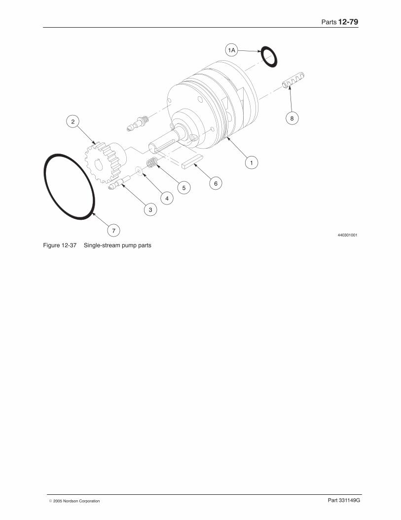
Parts 12-79
Part 331149G� 2005 Nordson Corporation
4403010017
3
6
1
8
1A
4
5
2
Figure 12-37 Single-stream pump parts
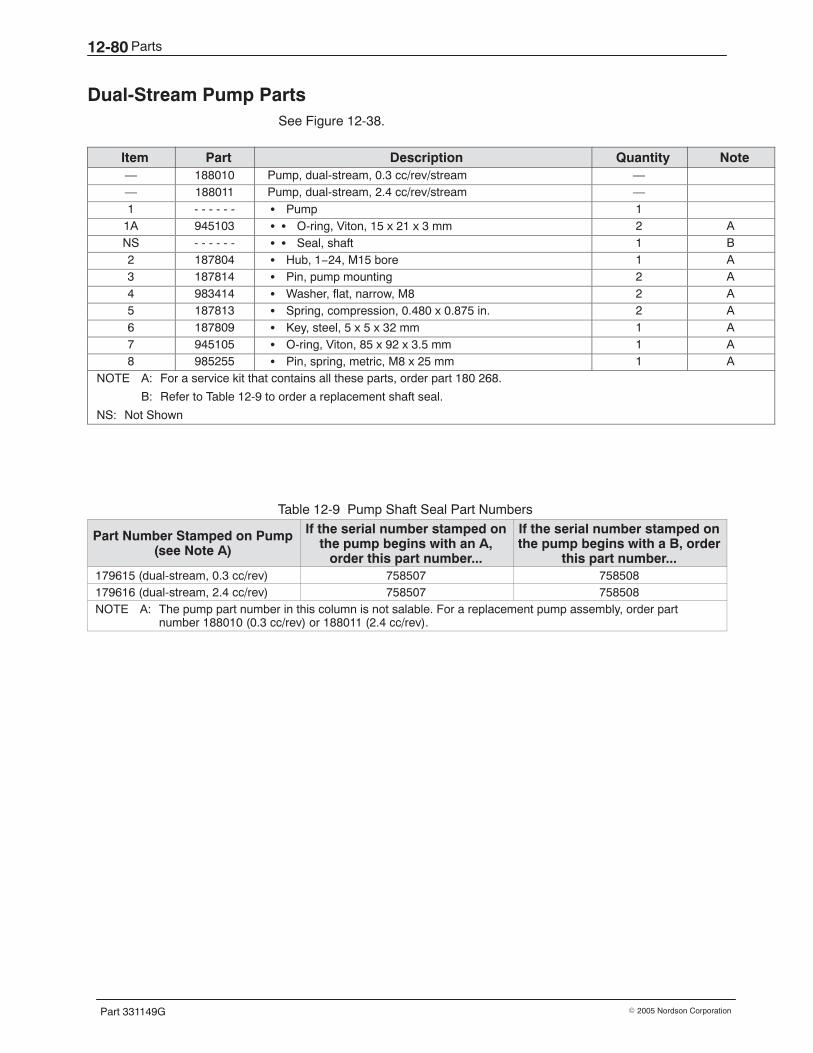
Parts12-80
Part 331149G � 2005 Nordson Corporation
Dual-Stream Pump Parts See Figure 12-38.
Item Part Description Quantity Note— 188010 Pump, dual-stream, 0.3 cc/rev/stream —— 188011 Pump, dual-stream, 2.4 cc/rev/stream —1 - - - - - - � Pump 1
1A 945103 � � O-ring, Viton, 15 x 21 x 3 mm 2 ANS - - - - - - � � Seal, shaft 1 B2 187804 � Hub, 1−24, M15 bore 1 A3 187814 � Pin, pump mounting 2 A4 983414 � Washer, flat, narrow, M8 2 A5 187813 � Spring, compression, 0.480 x 0.875 in. 2 A6 187809 � Key, steel, 5 x 5 x 32 mm 1 A7 945105 � O-ring, Viton, 85 x 92 x 3.5 mm 1 A8 985255 � Pin, spring, metric, M8 x 25 mm 1 A
NOTE A: For a service kit that contains all these parts, order part 180 268.
B: Refer to Table 12-9 to order a replacement shaft seal.
NS: Not Shown
Table 12-9 Pump Shaft Seal Part Numbers
Part Number Stamped on Pump(see Note A)
If the serial number stamped onthe pump begins with an A,
order this part number...
If the serial number stamped onthe pump begins with a B, order
this part number...179615 (dual-stream, 0.3 cc/rev) 758507 758508179616 (dual-stream, 2.4 cc/rev) 758507 758508NOTE A: The pump part number in this column is not salable. For a replacement pump assembly, order part
number 188010 (0.3 cc/rev) or 188011 (2.4 cc/rev).
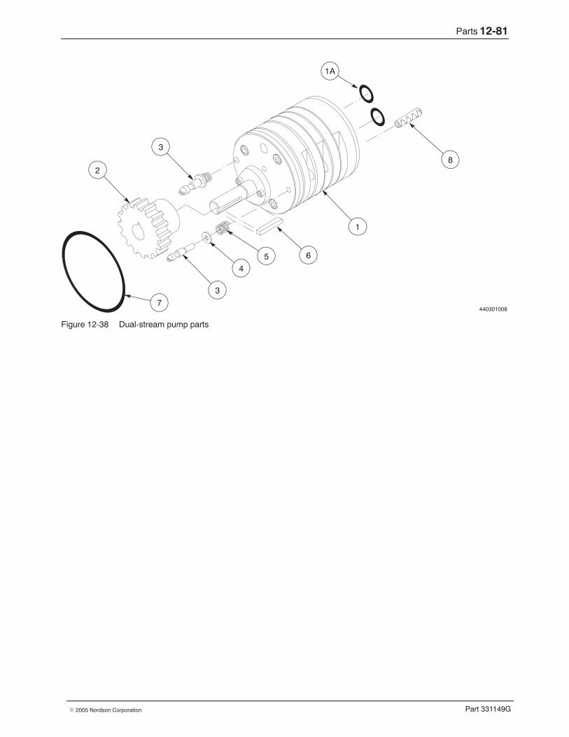
Parts 12-81
Part 331149G� 2005 Nordson Corporation
440301008
4
1
5 6
3
7
8
1A
2
3
Figure 12-38 Dual-stream pump parts
Parts12-82
Part 331149G � 2005 Nordson Corporation
Electrical System Parts Lists Part numbers for the most common electrical system components areprovided here. For a complete list of electrical system parts specific to yourmelter, refer to the electrical reference drawings provided with the melter.
240 VAC Electrical Parts Part Description Note
171227 Switch, motor, 40 A, 3∅171232 Knob, black1024840 Relay, Crouzet, 280 VAC, 12 A1024759 Relay, Crouzet, 280 VAC, 25 A151473 Snubber, contactor250532 Varister, 275 V, 130 joule, metal oxide168395 Filter235946 Holder, fuse, amp trap, type CC939954 Fuse, 5 A, slow blow251559 Fuse, 8 A, very fast-acting251560 Fuse, 10 A, very fast-acting187170 Fuse, 12.5 A, very fast-acting251568 Fuse, 16 A, very fast-acting
400 VAC Electrical Parts Part Description Note
171227 Switch, motor, 40 A, 3∅171232 Knob, black1024840 Relay, Crouzet, 280 VAC, 12 A1024759 Relay, Crouzet, 280 VAC, 25 A151473 Snubber, contactor250532 Varister, 275 V, 130 joule, metal oxide235496 Holder, fuse, amp trap, type CC939954 Fuse, 5 A, slow blow251559 Fuse, 8 A, very fast-acting251560 Fuse, 10 A, very fast-acting
XL3 Option Parts Part Description Note
171235 Relay, 24 VDC, double-pole, double-throw (DPDT)171236 Socket, relay172858 Clip, relay
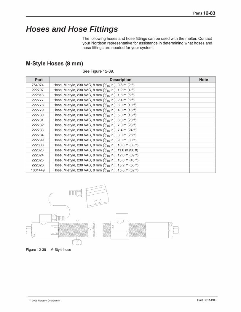
Parts 12-83
Part 331149G� 2005 Nordson Corporation
Hoses and Hose Fittings The following hoses and hose fittings can be used with the melter. Contactyour Nordson representative for assistance in determining what hoses andhose fittings are needed for your system.
M-Style Hoses (8 mm) See Figure 12-39.
Part Description Note754974 Hose, M-style, 230 VAC, 8 mm (5/16 in.), 0.6 m (2 ft)222797 Hose, M-style, 230 VAC, 8 mm (5/16 in.), 1.2 m (4 ft)222813 Hose, M-style, 230 VAC, 8 mm (5/16 in.), 1.8 m (6 ft)222777 Hose, M-style, 230 VAC, 8 mm (5/16 in.), 2.4 m (8 ft)222778 Hose, M-style, 230 VAC, 8 mm (5/16 in.), 3.0 m (10 ft)222779 Hose, M-style, 230 VAC, 8 mm (5/16 in.), 4.0 m (13 ft)222780 Hose, M-style, 230 VAC, 8 mm (5/16 in.), 5.0 m (16 ft)222781 Hose, M-style, 230 VAC, 8 mm (5/16 in.), 6.0 m (20 ft)222782 Hose, M-style, 230 VAC, 8 mm (5/16 in.), 7.0 m (23 ft)222783 Hose, M-style, 230 VAC, 8 mm (5/16 in.), 7.4 m (24 ft)222784 Hose, M-style, 230 VAC, 8 mm (5/16 in.), 8.0 m (26 ft)222799 Hose, M-style, 230 VAC, 8 mm (5/16 in.), 9.0 m (30 ft)222800 Hose, M-style, 230 VAC, 8 mm (5/16 in.), 10.0 m (33 ft)222823 Hose, M-style, 230 VAC, 8 mm (5/16 in.), 11.0 m (36 ft)222824 Hose, M-style, 230 VAC, 8 mm (5/16 in.), 12.0 m (39 ft)222825 Hose, M-style, 230 VAC, 8 mm (5/16 in.), 13.0 m (43 ft)222826 Hose, M-style, 230 VAC, 8 mm (5/16 in.), 15.2 m (50 ft)1001449 Hose, M-style, 230 VAC, 8 mm (5/16 in.), 15.8 m (52 ft)
Figure 12-39 M-Style hose
Parts12-84
Part 331149G � 2005 Nordson Corporation
M-Style Hoses (13 mm) See Figure 12-40.
Part Description Note222785 Hose, M-style, 230 VAC, 13 mm (1/2 in.), 1.2 m (4 ft)290624 Hose, M-style, 230 VAC, 13 mm (1/2 in.), 1.5 m (5 ft)222786 Hose, M-style, 230 VAC, 13 mm (1/2 in.), 1.8 m (6 ft)222787 Hose, M-style, 230 VAC, 13 mm (1/2 in.), 2.4 m (8 ft)222788 Hose, M-style, 230 VAC, 13 mm (1/2 in.), 3.0 m (10 ft)222789 Hose, M-style, 230 VAC, 13 mm (1/2 in.), 4.0 m (13 ft)222790 Hose, M-style, 230 VAC, 13 mm (1/2 in.), 5.0 m (16 ft)222791 Hose, M-style, 230 VAC, 13 mm (1/2 in.), 6.0 m (20 ft)222792 Hose, M-style, 230 VAC, 13 mm (1/2 in.), 7.0 m (23 ft)222793 Hose, M-style, 230 VAC, 13 mm (1/2 in.), 7.4 m (24 ft)222794 Hose, M-style, 230 VAC, 13 mm (1/2 in.), 8.0 m (26 ft)222795 Hose, M-style, 230 VAC, 13 mm (1/2 in.), 9.0 m (30 ft)222796 Hose, M-style, 230 VAC, 13 mm (1/2 in.), 10.0 m (33 ft)222817 Hose, M-style, 230 VAC, 13 mm (1/2 in.), 11.0 m (36 ft)222818 Hose, M-style, 230 VAC, 13 mm (1/2 in.), 12.0 m (39 ft)222819 Hose, M-style, 230 VAC, 13 mm (1/2 in.), 13.0 m (43 ft)1001448 Hose, M-style, 230 VAC, 13 mm (1/2 in.), 15.8 m (52 ft)222829 Hose, M-style, 230 VAC, 13 mm (1/2 in.), 16.0 m (52.5 ft)
Figure 12-40 M-Style hose
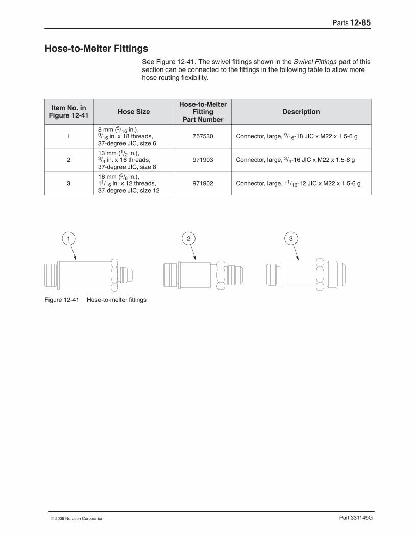
Parts 12-85
Part 331149G� 2005 Nordson Corporation
Hose-to-Melter Fittings See Figure 12-41. The swivel fittings shown in the Swivel Fittings part of thissection can be connected to the fittings in the following table to allow morehose routing flexibility.
Item No. inFigure 12-41 Hose Size
Hose-to-MelterFitting
Part NumberDescription
18 mm (5/16 in.),9/16 in. x 18 threads,37-degree JIC, size 6
757530 Connector, large, 9/16-18 JIC x M22 x 1.5-6 g
213 mm (1/2 in.),3/4 in. x 16 threads,37-degree JIC, size 8
971903 Connector, large, 3/4-16 JIC x M22 x 1.5-6 g
316 mm (5/8 in.),11/16 in. x 12 threads,37-degree JIC, size 12
971902 Connector, large, 11/16-12 JIC x M22 x 1.5-6 g
1 2 3
Figure 12-41 Hose-to-melter fittings
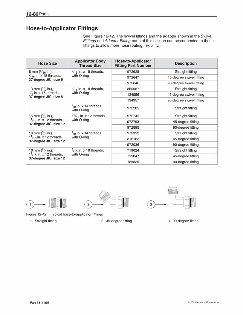
Parts12-86
Part 331149G � 2005 Nordson Corporation
Hose-to-Applicator Fittings See Figure 12-42. The swivel fittings and the adapter shown in the SwivelFittings and Adapter Fitting parts of this section can be connected to thesefittings to allow more hose routing flexibility.
Hose Size Applicator BodyThread Size
Hose-to-ApplicatorFitting Part Number Description
8 mm (5/16 in.),9/ i 18 h d
9/16 in. x 18 threads,i h O i
972628 Straight fitting( /16 ),9/16 in. x 18 threads,37-degree JIC size 6
/16 ,with O-ring 972647 45-degree swivel fitting
37-degree JIC, size 6972646 90-degree swivel fitting
13 mm (1/2 in.),3/ i 16 h d
9/16 in. x 18 threads,i h O i
860587 Straight fitting( /2 ),3/4 in. x 16 threads,37-degree JIC size 8
/16 ,with O-ring 134956 45-degree swivel fitting
37-degree JIC, size 8134957 90-degree swivel fitting
7/8 in. x 14 threads,with O-ring 972285 Straight fitting
16 mm (5/8 in.),11/ i 12 h d
11/16 in. x 12 threads,i h O i
972745 Straight fitting( /8 ),11/16 in. x 12 threads,37-degree JIC size 12
/16 ,with O-ring 972793 45-degree fitting
37-degree JIC, size 12972895 90-degree fitting
16 mm (5/8 in.),11/ i 12 h d
7/8 in. x 14 threads,i h O i
972392 Straight fitting( /8 ),11/16 in. x 12 threads,37-degree JIC size 12
/8 ,with O-ring 816162 45-degree fitting
37-degree JIC, size 12972036 90-degree fitting
16 mm (5/8 in.),11/ i 12 h d
9/16 in. x 18 threads,i h O i
719024 Straight fitting( /8 ),11/16 in. x 12 threads,37-degree JIC size 12
/16 ,with O-ring 719047 45-degree fitting
37-degree JIC, size 12188825 90-degree fitting
1 2 3
Figure 12-42 Typical hose-to-applicator fittings
1. Straight fitting 2. 45-degree fitting 3. 90-degree fitting
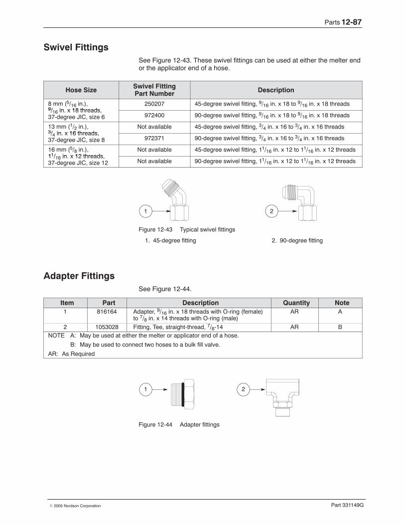
Parts 12-87
Part 331149G� 2005 Nordson Corporation
Swivel Fittings See Figure 12-43. These swivel fittings can be used at either the melter endor the applicator end of a hose.
Hose Size Swivel FittingPart Number Description
8 mm (5/16 in.),9/ in x 18 threads
250207 45-degree swivel fitting, 9/16 in. x 18 to 9/16 in. x 18 threads9/16 in. x 18 threads,37-degree JIC, size 6 972400 90-degree swivel fitting, 9/16 in. x 18 to 9/16 in. x 18 threads
13 mm (1/2 in.),3/ in x 16 threads
Not available 45-degree swivel fitting, 3/4 in. x 16 to 3/4 in. x 16 threads3/4 in. x 16 threads,37-degree JIC, size 8 972371 90-degree swivel fitting, 3/4 in. x 16 to 3/4 in. x 16 threads
16 mm (5/8 in.),11/ in x 12 threads
Not available 45-degree swivel fitting, 11/16 in. x 12 to 11/16 in. x 12 threads11/16 in. x 12 threads,37-degree JIC, size 12 Not available 90-degree swivel fitting, 11/16 in. x 12 to 11/16 in. x 12 threads
1 2
Figure 12-43 Typical swivel fittings
1. 45-degree fitting 2. 90-degree fitting
Adapter Fittings See Figure 12-44.
Item Part Description Quantity Note1 816164 Adapter, 9/16 in. x 18 threads with O-ring (female)
to 7/8 in. x 14 threads with O-ring (male)AR A
2 1053028 Fitting, Tee, straight-thread, 7/8-14 AR BNOTE A: May be used at either the melter or applicator end of a hose.
B: May be used to connect two hoses to a bulk fill valve.
AR: As Required
1 2
Figure 12-44 Adapter fittings
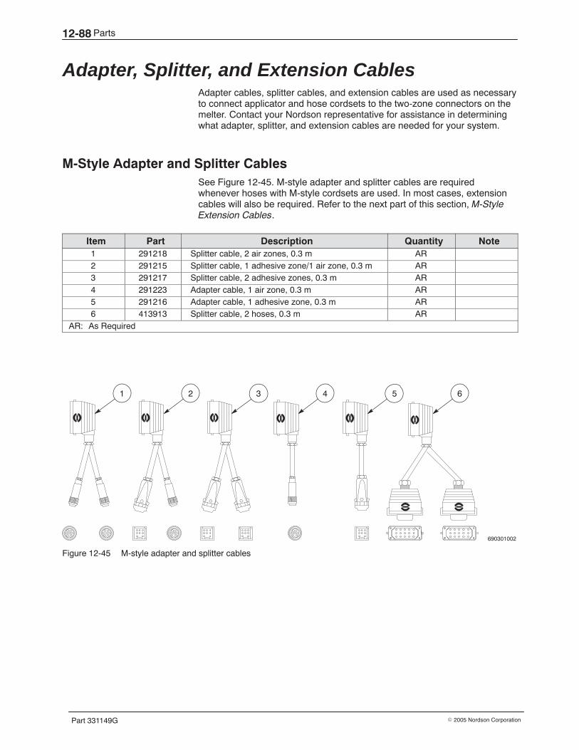
Parts12-88
Part 331149G � 2005 Nordson Corporation
Adapter, Splitter, and Extension Cables Adapter cables, splitter cables, and extension cables are used as necessaryto connect applicator and hose cordsets to the two-zone connectors on themelter. Contact your Nordson representative for assistance in determiningwhat adapter, splitter, and extension cables are needed for your system.
M-Style Adapter and Splitter Cables See Figure 12-45. M-style adapter and splitter cables are requiredwhenever hoses with M-style cordsets are used. In most cases, extensioncables will also be required. Refer to the next part of this section, M-StyleExtension Cables.
Item Part Description Quantity Note1 291218 Splitter cable, 2 air zones, 0.3 m AR2 291215 Splitter cable, 1 adhesive zone/1 air zone, 0.3 m AR3 291217 Splitter cable, 2 adhesive zones, 0.3 m AR4 291223 Adapter cable, 1 air zone, 0.3 m AR5 291216 Adapter cable, 1 adhesive zone, 0.3 m AR6 413913 Splitter cable, 2 hoses, 0.3 m AR
AR: As Required
690301002
1 2 3 4 5 6
Figure 12-45 M-style adapter and splitter cables
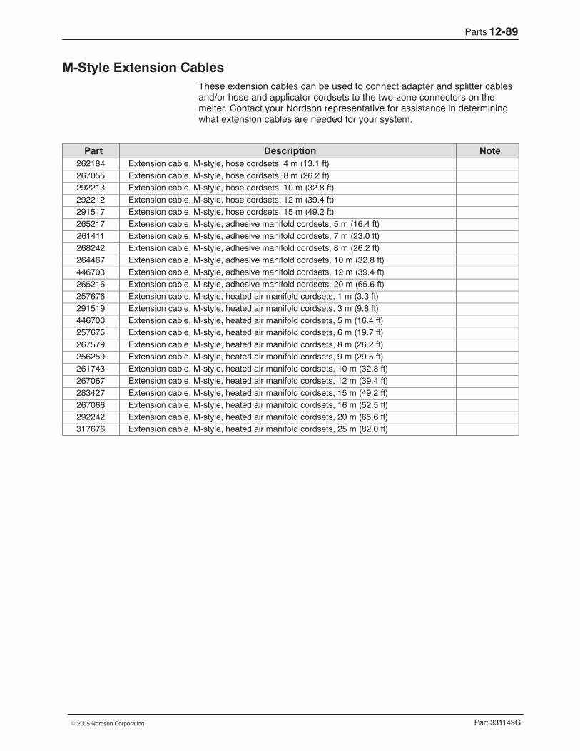
Parts 12-89
Part 331149G� 2005 Nordson Corporation
M-Style Extension Cables These extension cables can be used to connect adapter and splitter cablesand/or hose and applicator cordsets to the two-zone connectors on themelter. Contact your Nordson representative for assistance in determiningwhat extension cables are needed for your system.
Part Description Note262184 Extension cable, M-style, hose cordsets, 4 m (13.1 ft)267055 Extension cable, M-style, hose cordsets, 8 m (26.2 ft)292213 Extension cable, M-style, hose cordsets, 10 m (32.8 ft)292212 Extension cable, M-style, hose cordsets, 12 m (39.4 ft)291517 Extension cable, M-style, hose cordsets, 15 m (49.2 ft)265217 Extension cable, M-style, adhesive manifold cordsets, 5 m (16.4 ft)261411 Extension cable, M-style, adhesive manifold cordsets, 7 m (23.0 ft)268242 Extension cable, M-style, adhesive manifold cordsets, 8 m (26.2 ft)264467 Extension cable, M-style, adhesive manifold cordsets, 10 m (32.8 ft)446703 Extension cable, M-style, adhesive manifold cordsets, 12 m (39.4 ft)265216 Extension cable, M-style, adhesive manifold cordsets, 20 m (65.6 ft)257676 Extension cable, M-style, heated air manifold cordsets, 1 m (3.3 ft)291519 Extension cable, M-style, heated air manifold cordsets, 3 m (9.8 ft)446700 Extension cable, M-style, heated air manifold cordsets, 5 m (16.4 ft)257675 Extension cable, M-style, heated air manifold cordsets, 6 m (19.7 ft)267579 Extension cable, M-style, heated air manifold cordsets, 8 m (26.2 ft)256259 Extension cable, M-style, heated air manifold cordsets, 9 m (29.5 ft)261743 Extension cable, M-style, heated air manifold cordsets, 10 m (32.8 ft)267067 Extension cable, M-style, heated air manifold cordsets, 12 m (39.4 ft)283427 Extension cable, M-style, heated air manifold cordsets, 15 m (49.2 ft)267066 Extension cable, M-style, heated air manifold cordsets, 16 m (52.5 ft)292242 Extension cable, M-style, heated air manifold cordsets, 20 m (65.6 ft)317676 Extension cable, M-style, heated air manifold cordsets, 25 m (82.0 ft)
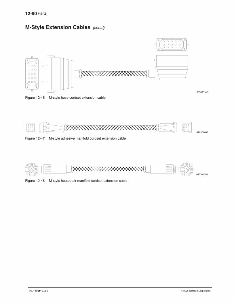
Parts12-90
Part 331149G � 2005 Nordson Corporation
M-Style Extension Cables (contd)
690301005
ÌÌÌÌÌÌÌÌÌÌÌÌ
Figure 12-46 M-style hose cordset extension cable
690301003
ÌÌÌÌÌÌÌÌÌÌÌÌÌÌÌÌÌÌÌÌÌÌÌÌÌÌÌÌÌÌÌÌ
Figure 12-47 M-style adhesive manifold cordset extension cable
ÌÌÌÌÌÌÌÌÌÌÌÌÌÌÌÌÌÌÌÌÌÌÌÌÌÌ 690301004
Figure 12-48 M-style heated air manifold cordset extension cable

Parts 12-91
Part 331149G� 2005 Nordson Corporation
This page intentionally left blank.
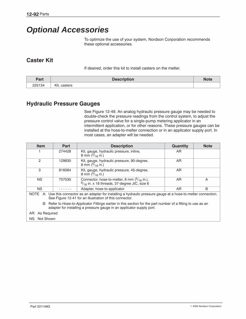
Parts12-92
Part 331149G � 2005 Nordson Corporation
Optional Accessories To optimize the use of your system, Nordson Corporation recommendsthese optional accessories.
Caster Kit If desired, order this kit to install casters on the melter.
Part Description Note225134 Kit, casters
Hydraulic Pressure Gauges See Figure 12-49. An analog hydraulic pressure gauge may be needed todouble-check the pressure readings from the control system, to adjust thepressure control valve for a single-pump metering applicator in anintermittent application, or for other reasons. These pressure gauges can beinstalled at the hose-to-melter connection or in an applicator supply port. Inmost cases, an adapter will be needed.
Item Part Description Quantity Note1 274428 Kit, gauge, hydraulic pressure, inline,
8 mm (5/16 in.)AR
2 129830 Kit, gauge, hydraulic pressure, 90-degree,8 mm (5/16 in.)
AR
3 816084 Kit, gauge, hydraulic pressure, 45-degree,8 mm (5/16 in.)
AR
NS 757530 Connector, hose-to-melter, 8 mm (5/16 in.),9/16 in. x 18 threads, 37-degree JIC, size 6
AR A
NS - - - - - - Adapter, hose-to-applicator AR BNOTE A: Use this connector as an adapter for installing a hydraulic pressure gauge at a hose-to-melter connection.
See Figure 12-41 for an illustration of this connector.
B: Refer to Hose-to-Applicator Fittings earlier in this section for the part number of a fitting to use as anadapter for installing a pressure gauge in an applicator supply port.
AR: As Required
NS: Not Shown
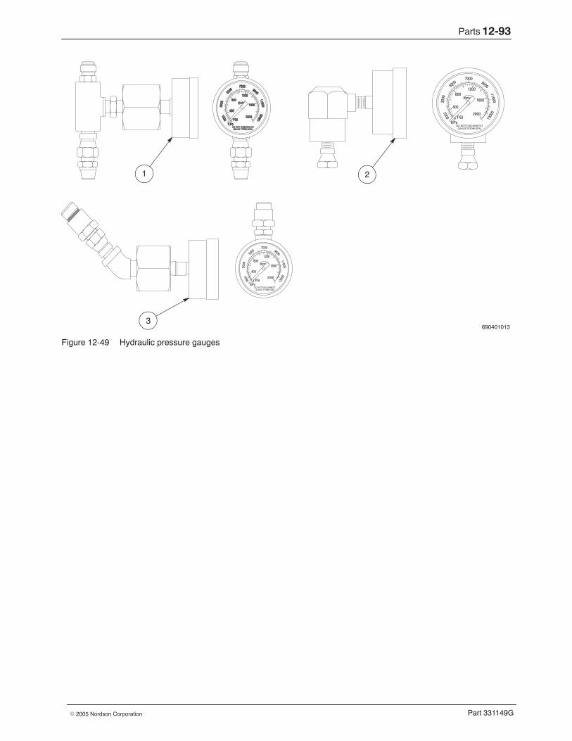
Parts 12-93
Part 331149G� 2005 Nordson Corporation
690401013
1 2
3
Figure 12-49 Hydraulic pressure gauges
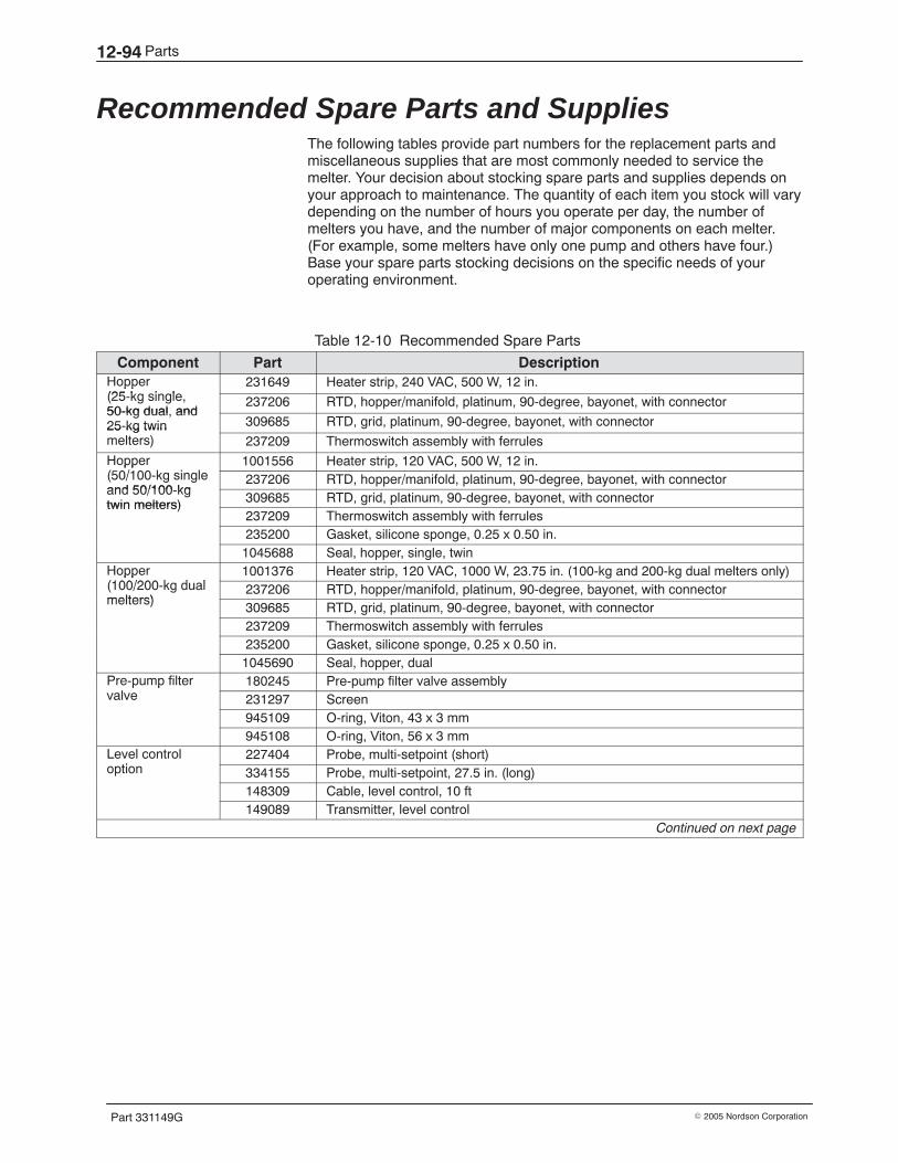
Parts12-94
Part 331149G � 2005 Nordson Corporation
Recommended Spare Parts and Supplies The following tables provide part numbers for the replacement parts andmiscellaneous supplies that are most commonly needed to service themelter. Your decision about stocking spare parts and supplies depends onyour approach to maintenance. The quantity of each item you stock will varydepending on the number of hours you operate per day, the number ofmelters you have, and the number of major components on each melter.(For example, some melters have only one pump and others have four.)Base your spare parts stocking decisions on the specific needs of youroperating environment.
Table 12-10 Recommended Spare Parts
Component Part DescriptionHopper(25 k i l
231649 Heater strip, 240 VAC, 500 W, 12 in.pp(25-kg single,50-kg dual and
237206 RTD, hopper/manifold, platinum, 90-degree, bayonet, with connector50-kg dual, and25-kg twin 309685 RTD, grid, platinum, 90-degree, bayonet, with connector25 kg twinmelters) 237209 Thermoswitch assembly with ferrules
Hopper(50/100 k i l
1001556 Heater strip, 120 VAC, 500 W, 12 in.pp(50/100-kg singleand 50/100 kg
237206 RTD, hopper/manifold, platinum, 90-degree, bayonet, with connectorand 50/100-kgtwin melters) 309685 RTD, grid, platinum, 90-degree, bayonet, with connectortwin melters)
237209 Thermoswitch assembly with ferrules235200 Gasket, silicone sponge, 0.25 x 0.50 in.1045688 Seal, hopper, single, twin
Hopper(100/200 k d l
1001376 Heater strip, 120 VAC, 1000 W, 23.75 in. (100-kg and 200-kg dual melters only)pp(100/200-kg dualmelters)
237206 RTD, hopper/manifold, platinum, 90-degree, bayonet, with connectormelters)
309685 RTD, grid, platinum, 90-degree, bayonet, with connector237209 Thermoswitch assembly with ferrules235200 Gasket, silicone sponge, 0.25 x 0.50 in.1045690 Seal, hopper, dual
Pre-pump filterl
180245 Pre-pump filter valve assemblyp pvalve 231297 Screen
945109 O-ring, Viton, 43 x 3 mm945108 O-ring, Viton, 56 x 3 mm
Level controli
227404 Probe, multi-setpoint (short)option 334155 Probe, multi-setpoint, 27.5 in. (long)
148309 Cable, level control, 10 ft149089 Transmitter, level control
Continued on next page
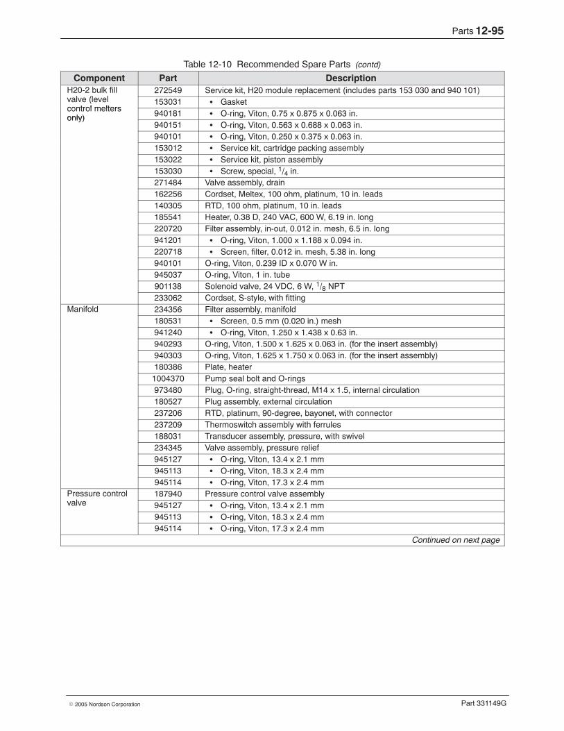
Parts 12-95
Part 331149G� 2005 Nordson Corporation
Table 12-10 Recommended Spare Parts (contd)
Component Part DescriptionH20-2 bulk fill
l (l l272549 Service kit, H20 module replacement (includes parts 153 030 and 940 101)
valve (levelcontrol melters
153031 � Gasketcontrol meltersonly) 940181 � O-ring, Viton, 0.75 x 0.875 x 0.063 in.only)
940151 � O-ring, Viton, 0.563 x 0.688 x 0.063 in.940101 � O-ring, Viton, 0.250 x 0.375 x 0.063 in.153012 � Service kit, cartridge packing assembly153022 � Service kit, piston assembly153030 � Screw, special, 1/4 in.271484 Valve assembly, drain162256 Cordset, Meltex, 100 ohm, platinum, 10 in. leads140305 RTD, 100 ohm, platinum, 10 in. leads185541 Heater, 0.38 D, 240 VAC, 600 W, 6.19 in. long220720 Filter assembly, in-out, 0.012 in. mesh, 6.5 in. long941201 � O-ring, Viton, 1.000 x 1.188 x 0.094 in.220718 � Screen, filter, 0.012 in. mesh, 5.38 in. long940101 O-ring, Viton, 0.239 ID x 0.070 W in.945037 O-ring, Viton, 1 in. tube901138 Solenoid valve, 24 VDC, 6 W, 1/8 NPT233062 Cordset, S-style, with fitting
Manifold 234356 Filter assembly, manifold180531 � Screen, 0.5 mm (0.020 in.) mesh941240 � O-ring, Viton, 1.250 x 1.438 x 0.63 in.940293 O-ring, Viton, 1.500 x 1.625 x 0.063 in. (for the insert assembly)940303 O-ring, Viton, 1.625 x 1.750 x 0.063 in. (for the insert assembly)180386 Plate, heater1004370 Pump seal bolt and O-rings973480 Plug, O-ring, straight-thread, M14 x 1.5, internal circulation180527 Plug assembly, external circulation237206 RTD, platinum, 90-degree, bayonet, with connector237209 Thermoswitch assembly with ferrules188031 Transducer assembly, pressure, with swivel234345 Valve assembly, pressure relief945127 � O-ring, Viton, 13.4 x 2.1 mm945113 � O-ring, Viton, 18.3 x 2.4 mm945114 � O-ring, Viton, 17.3 x 2.4 mm
Pressure controll
187940 Pressure control valve assemblyvalve 945127 � O-ring, Viton, 13.4 x 2.1 mm
945113 � O-ring, Viton, 18.3 x 2.4 mm945114 � O-ring, Viton, 17.3 x 2.4 mm
Continued on next page
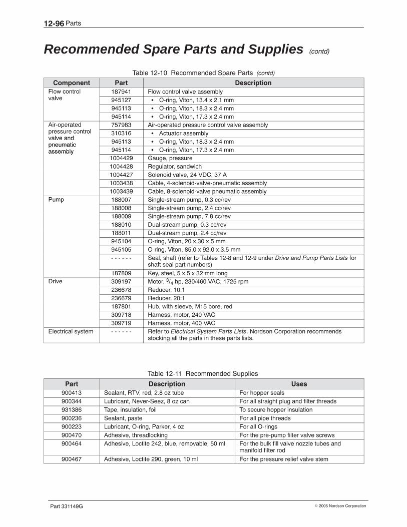
Parts12-96
Part 331149G � 2005 Nordson Corporation
Recommended Spare Parts and Supplies (contd)
Table 12-10 Recommended Spare Parts (contd)
Component Part DescriptionFlow control
l187941 Flow control valve assembly
valve 945127 � O-ring, Viton, 13.4 x 2.1 mm945113 � O-ring, Viton, 18.3 x 2.4 mm945114 � O-ring, Viton, 17.3 x 2.4 mm
Air-operated l
757983 Air-operated pressure control valve assemblyppressure controlvalve and
310316 � Actuator assemblyvalve andpneumatic 945113 � O-ring, Viton, 18.3 x 2.4 mmpneumaticassembly 945114 � O-ring, Viton, 17.3 x 2.4 mmassembly
1004429 Gauge, pressure1004428 Regulator, sandwich1004427 Solenoid valve, 24 VDC, 37 A1003438 Cable, 4-solenoid-valve-pneumatic assembly1003439 Cable, 8-solenoid-valve pneumatic assembly
Pump 188007 Single-stream pump, 0.3 cc/revp188008 Single-stream pump, 2.4 cc/rev188009 Single-stream pump, 7.8 cc/rev188010 Dual-stream pump, 0.3 cc/rev188011 Dual-stream pump, 2.4 cc/rev945104 O-ring, Viton, 20 x 30 x 5 mm945105 O-ring, Viton, 85.0 x 92.0 x 3.5 mm- - - - - - Seal, shaft (refer to Tables 12-8 and 12-9 under Drive and Pump Parts Lists for
shaft seal part numbers)187809 Key, steel, 5 x 5 x 32 mm long
Drive 309197 Motor, 3/4 hp, 230/460 VAC, 1725 rpm236678 Reducer, 10:1236679 Reducer, 20:1187801 Hub, with sleeve, M15 bore, red309718 Harness, motor, 240 VAC309719 Harness, motor, 400 VAC
Electrical system - - - - - - Refer to Electrical System Parts Lists. Nordson Corporation recommendsstocking all the parts in these parts lists.
Table 12-11 Recommended Supplies
Part Description Uses900413 Sealant, RTV, red, 2.8 oz tube For hopper seals900344 Lubricant, Never-Seez, 8 oz can For all straight plug and filter threads931386 Tape, insulation, foil To secure hopper insulation900236 Sealant, paste For all pipe threads900223 Lubricant, O-ring, Parker, 4 oz For all O-rings900470 Adhesive, threadlocking For the pre-pump filter valve screws900464 Adhesive, Loctite 242, blue, removable, 50 ml For the bulk fill valve nozzle tubes and
manifold filter rod
900467 Adhesive, Loctite 290, green, 10 ml For the pressure relief valve stem
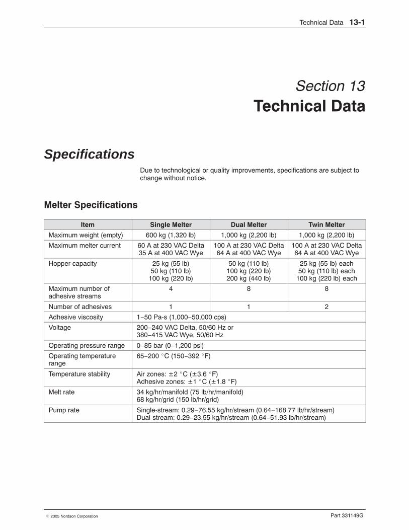
Technical Data 13-1
Part 331149G� 2005 Nordson Corporation
Section 13Technical Data
Specifications Due to technological or quality improvements, specifications are subject tochange without notice.
Melter Specifications
Item Single Melter Dual Melter Twin Melter
Maximum weight (empty) 600 kg (1,320 lb) 1,000 kg (2,200 lb) 1,000 kg (2,200 lb)
Maximum melter current 60 A at 230 VAC Delta35 A at 400 VAC Wye
100 A at 230 VAC Delta64 A at 400 VAC Wye
100 A at 230 VAC Delta64 A at 400 VAC Wye
Hopper capacity 25 kg (55 lb)50 kg (110 lb)
100 kg (220 lb)
50 kg (110 lb)100 kg (220 lb)200 kg (440 lb)
25 kg (55 lb) each50 kg (110 lb) each
100 kg (220 lb) each
Maximum number ofadhesive streams
4 8 8
Number of adhesives 1 1 2
Adhesive viscosity 1−50 Pa-s (1,000−50,000 cps)
Voltage 200−240 VAC Delta, 50/60 Hz or380−415 VAC Wye, 50/60 Hz
Operating pressure range 0−85 bar (0−1,200 psi)
Operating temperaturerange
65−200 �C (150−392 �F)
Temperature stability Air zones: ±2 �C (±3.6 �F)Adhesive zones: ±1 �C (±1.8 �F)
Melt rate 34 kg/hr/manifold (75 lb/hr/manifold)68 kg/hr/grid (150 lb/hr/grid)
Pump rate Single-stream: 0.29−76.55 kg/hr/stream (0.64−168.77 lb/hr/stream)Dual-stream: 0.29−23.55 kg/hr/stream (0.64−51.93 lb/hr/stream)
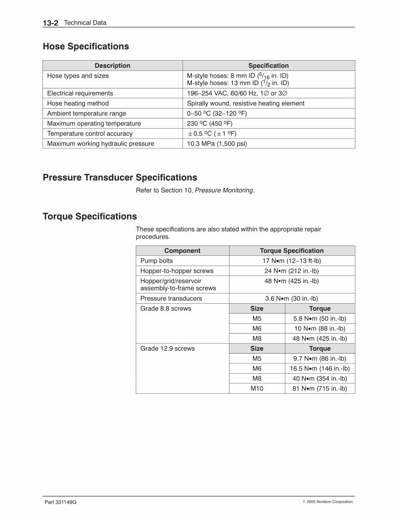
Technical Data13-2
Part 331149G � 2005 Nordson Corporation
Hose Specifications
Description Specification
Hose types and sizes M-style hoses: 8 mm ID (5/16 in. ID)M-style hoses: 13 mm ID (1/2 in. ID)
Electrical requirements 196−254 VAC, 60/60 Hz, 1∅ or 3∅Hose heating method Spirally wound, resistive heating element
Ambient temperature range 0−50 oC (32−120 oF)
Maximum operating temperature 230 oC (450 oF)
Temperature control accuracy �0.5 oC (�1 oF)
Maximum working hydraulic pressure 10.3 MPa (1,500 psi)
Pressure Transducer Specifications Refer to Section 10, Pressure Monitoring.
Torque Specifications These specifications are also stated within the appropriate repairprocedures.
Component Torque Specification
Pump bolts 17 N•m (12−13 ft-lb)
Hopper-to-hopper screws 24 N�m (212 in.-lb)
Hopper/grid/reservoirassembly-to-frame screws
48 N�m (425 in.-lb)
Pressure transducers 3.6 N•m (30 in.-lb)
Grade 8.8 screws Size Torque
M5 5.8 N•m (50 in.-lb)
M6 10 N•m (88 in.-lb)
M8 48 N•m (425 in.-lb)
Grade 12.9 screws Size Torque
M5 9.7 N•m (86 in.-lb)
M6 16.5 N•m (146 in.-lb)
M8 40 N•m (354 in.-lb)
M10 81 N•m (715 in.-lb)
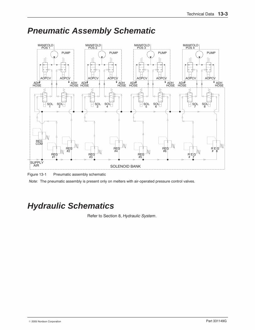
Technical Data 13-3
Part 331149G� 2005 Nordson Corporation
Pneumatic Assembly Schematic
SOLENOID BNKS U L Y
I R
U M
O C V O C V
MANIFOLDPOS 1
ADHHOSE
ADH
S O L1
S O L2
R E GC O M
R E G# 1
R E G# 2
U M
O C V O C V
MANIFOLDPOS 2
ADHHOSE
ADHHOSE
S O L3
S O L4
R E G# 3
R E G# 4
U M
O C V O C V
MANIFOLDPOS 3
ADHHOSE
ADHHOSE
S O L5
S O L6
R E G# 5
R E G# 6
U M
O C V O C V
MANIFOLDPOS 4
ADHHOSE
ADHHOSE
S O L7
S O L8
R E G# 7
R E G# 8
SOLENOID BANKSUPPLY
AIR
PUMP
AOPCV AOPCV
HOSE
SOL1
SOL2
REGCOM
REG#1
REG#2
PUMP
AOPCV AOPCV
SOL3
SOL4
REG#3
REG#4
PUMP
AOPCV AOPCV
SOL5
SOL6
REG#5
REG#6
PUMP
AOPCV AOPCV
SOL7
SOL8
R E G# 7
R E G# 8
Figure 13-1 Pneumatic assembly schematic
Note: The pneumatic assembly is present only on melters with air-operated pressure control valves.
Hydraulic Schematics Refer to Section 8, Hydraulic System.
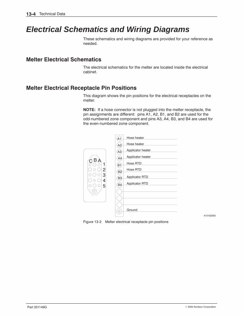
Technical Data13-4
Part 331149G � 2005 Nordson Corporation
Electrical Schematics and Wiring Diagrams These schematics and wiring diagrams are provided for your reference asneeded.
Melter Electrical Schematics The electrical schematics for the melter are located inside the electricalcabinet.
Melter Electrical Receptacle Pin Positions This diagram shows the pin positions for the electrical receptacles on themelter.
NOTE: If a hose connector is not plugged into the melter receptacle, thepin assignments are different: pins A1, A2, B1, and B2 are used for theodd-numbered zone component and pins A3, A4, B3, and B4 are used forthe even-numbered zone component.
410102005
A1
A2
A3
A4
B1
B2
B4
Hose heater
Applicator heater
Hose RTD
Applicator RTD
Applicator RTD
Applicator heater
Hose RTD
Hose heater
B3
Ground
C B A12345
Figure 13-2 Melter electrical receptacle pin positions
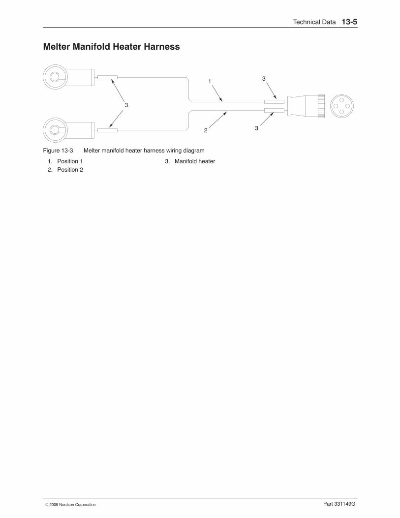
Technical Data 13-5
Part 331149G� 2005 Nordson Corporation
Melter Manifold Heater Harness
1
2
3
3
3
Figure 13-3 Melter manifold heater harness wiring diagram
1. Position 12. Position 2
3. Manifold heater
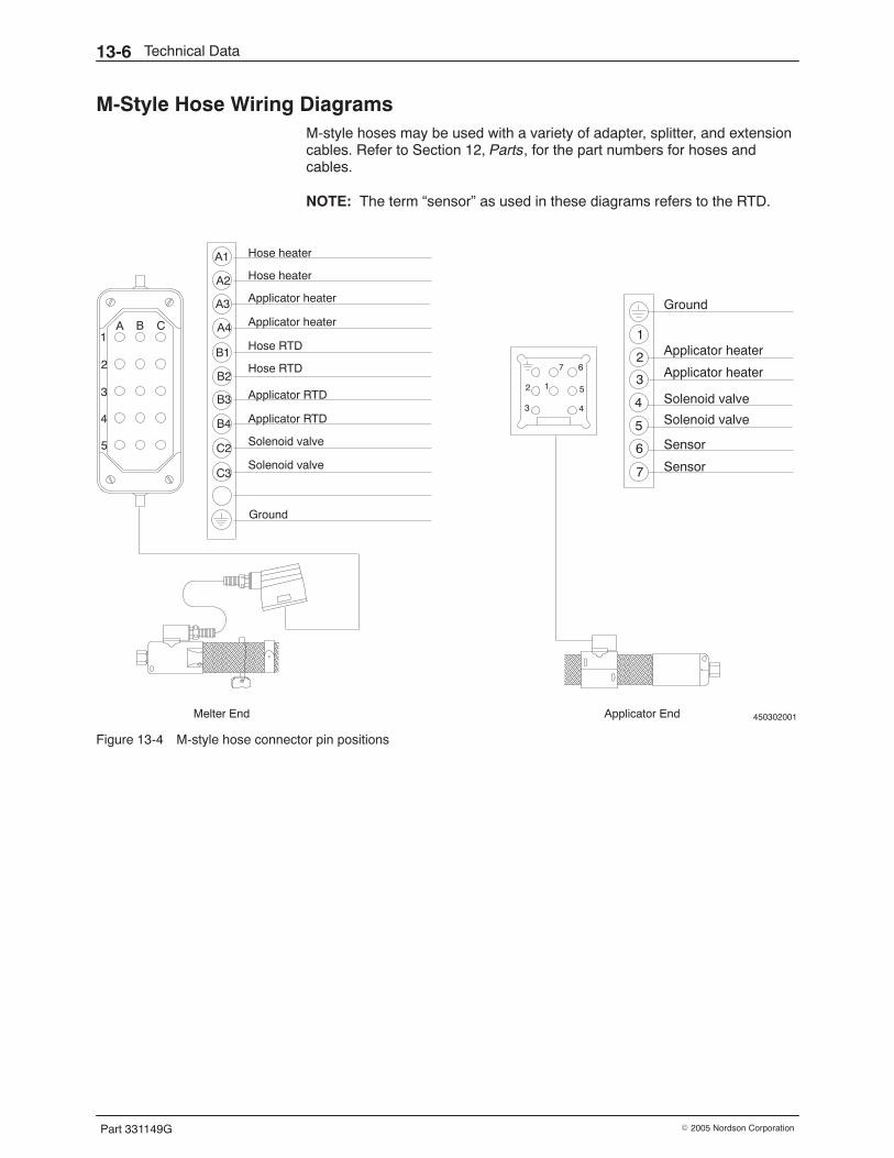
Technical Data13-6
Part 331149G � 2005 Nordson Corporation
M-Style Hose Wiring Diagrams M-style hoses may be used with a variety of adapter, splitter, and extensioncables. Refer to Section 12, Parts, for the part numbers for hoses andcables.
NOTE: The term “sensor” as used in these diagrams refers to the RTD.
450302001
C1
A B
3
2
4
5
12
3 4
5
67
1
2
3
4
5
6
7
Ground
A1
A2
A3
A4
B1
B2
B4
Hose heater
Applicator heater
Hose RTD
Applicator RTD
Applicator RTD
Applicator heater
Hose RTD
Hose heater
B3
Ground
Applicator EndMelter End
Applicator heater
Applicator heater
Solenoid valve
Solenoid valve
Sensor
SensorC2
C3
Solenoid valve
Solenoid valve
Figure 13-4 M-style hose connector pin positions
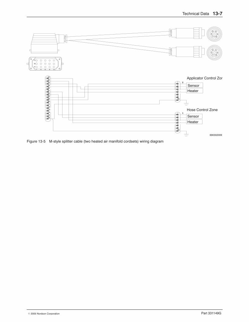
Technical Data 13-7
Part 331149G� 2005 Nordson Corporation
690302009
SensorHeater
Applicator Control Zon
Hose Control Zone
Sensor
Heater
A1
A2
A3
A4
A5
B1
B2
B3
B4
B5
C1
C2
C3
C4
C5
PE
1
2
3
4
5
6
PE
1
2
3
4
5
6
PE
A
12
3 4
56
12
3 4
56
B
AB
C1 2 3 4 5
Figure 13-5 M-style splitter cable (two heated air manifold cordsets) wiring diagram
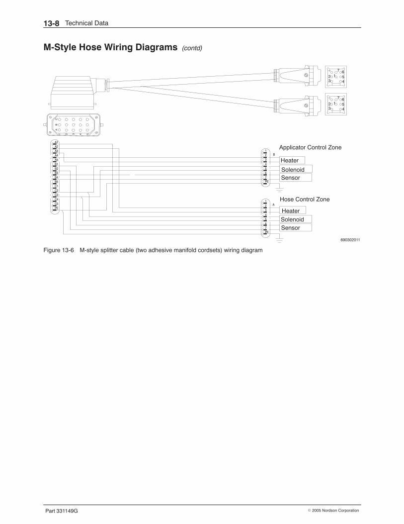
Technical Data13-8
Part 331149G � 2005 Nordson Corporation
M-Style Hose Wiring Diagrams (contd)
690302011
Solenoid
Applicator Control Zone
Hose Control Zone
HeaterSolenoid
A1
A2
A3
A4
A5
B1
B2
B3
B4
B5
C1
C2
C3
C4
C5
PE
1
2
3
4
5
6
PE
1
2
3
4
5
6
PE
A
B
Heater
Sensor
7 Sensor
7
AB
C1 2 3 4 5
123 4
567
123 4
567
Figure 13-6 M-style splitter cable (two adhesive manifold cordsets) wiring diagram
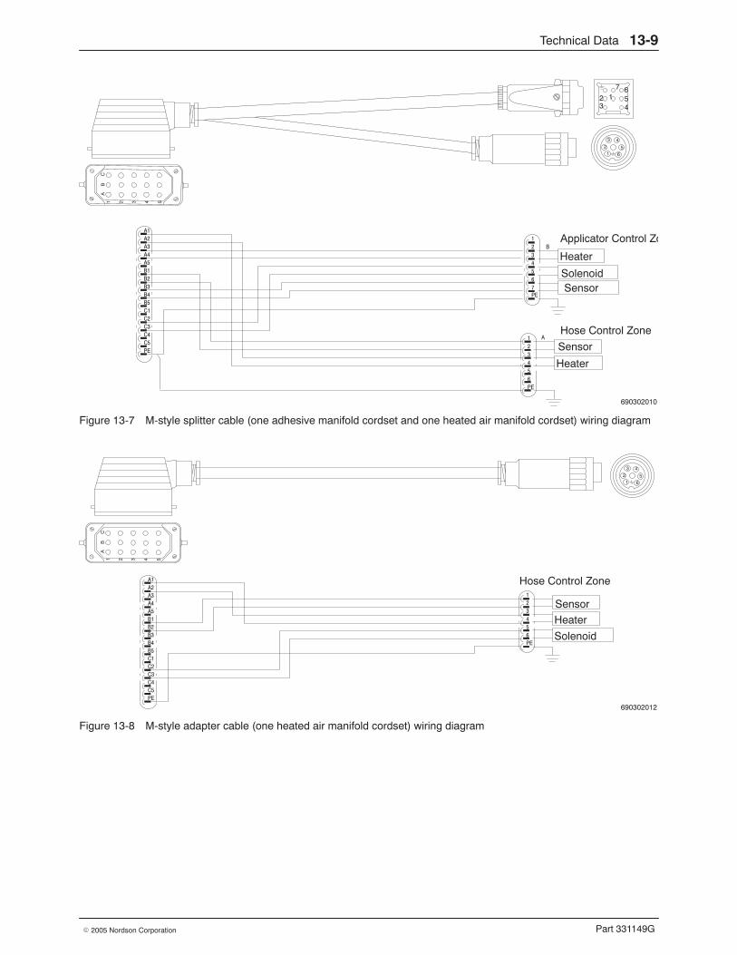
Technical Data 13-9
Part 331149G� 2005 Nordson Corporation
690302010
Sensor
Heater
A1
A2
A3
A4
A5
B1
B2
B3
B4
B5
C1
C2
C3
C4
C5
PE
1
2
3
4
5
6
PE
A
Applicator Control Zo
Hose Control Zone
Solenoid
1
2
3
4
5
6
PE
B
Heater
7 Sensor
AB
C1 2 3 4 5
123 4
567
12
3 4
56
Figure 13-7 M-style splitter cable (one adhesive manifold cordset and one heated air manifold cordset) wiring diagram
690302012
Solenoid
Hose Control ZoneA1
A2
A3
A4
A5
B1
B2
B3
B4
B5
C1
C2
C3
C4
C5
PE
1
2
3
4
5
6
PE
Heater
Sensor
AB
C1 2 3 4 5
12
3 4
56
Figure 13-8 M-style adapter cable (one heated air manifold cordset) wiring diagram
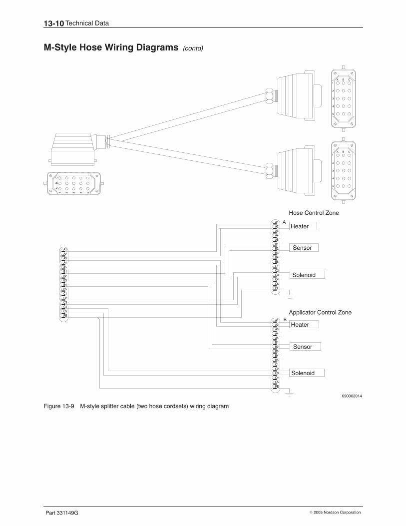
Technical Data13-10
Part 331149G � 2005 Nordson Corporation
M-Style Hose Wiring Diagrams (contd)
690302014
Solenoid
Hose Control Zone
A1
A2
A3
A4
A5
B1
B2
B3
B4
B5
C1
C2
C3
C4
C5
PE
Heater
Sensor
A
B
A1
A2
A3
A4
A5
B1
B2
B3
B4
B5
C1
C2
C3
C4
C5
PE
A1
A2
A3
A4
A5
B1
B2
B3
B4
B5
C1
C2
C3
C4
C5
PE
Solenoid
Heater
Sensor
Applicator Control Zone
AB
C1 2 3 4 5
C1
A B
3
2
4
5
C1
A B
3
2
4
5
Figure 13-9 M-style splitter cable (two hose cordsets) wiring diagram
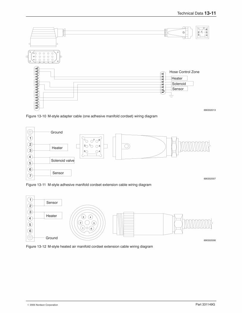
Technical Data 13-11
Part 331149G� 2005 Nordson Corporation
690302013
Solenoid
Hose Control ZoneA1
A2
A3
A4
A5
B1
B2
B3
B4
B5
C1
C2
C3
C4
C5
PE
1
2
3
4
5
6
PE
Heater
Sensor7
AB
C1 2 3 4 5
123 4
567
Figure 13-10 M-style adapter cable (one adhesive manifold cordset) wiring diagram
690302007
12
3 4
5
671
2
3
4
5
6
7
Heater
Sensor
Solenoid valve
Ground
Figure 13-11 M-style adhesive manifold cordset extension cable wiring diagram
690302006
1
2
3 4
5
6
1
2
3
4
5
6
Heater
Sensor
Ground
Figure 13-12 M-style heated air manifold cordset extension cable wiring diagram
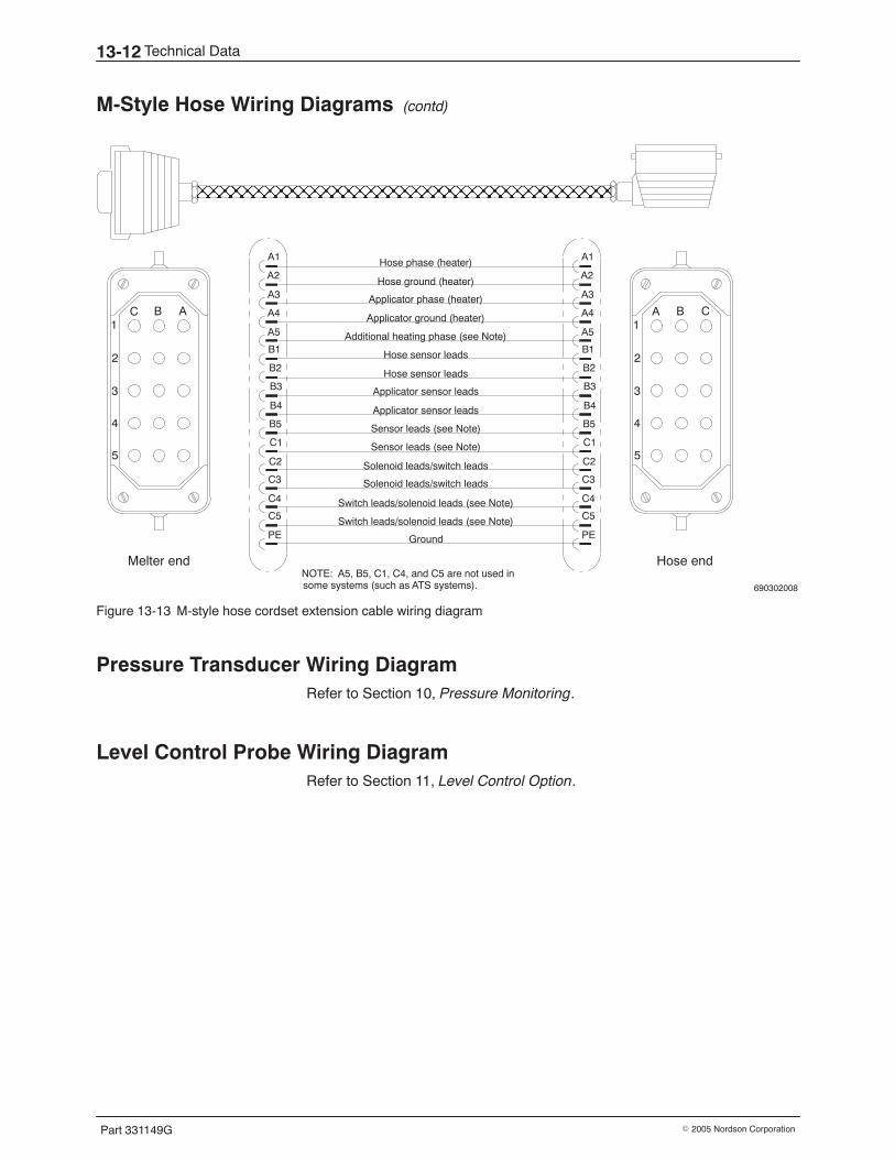
Technical Data13-12
Part 331149G � 2005 Nordson Corporation
M-Style Hose Wiring Diagrams (contd)
690302008
A1
C B
3
2
4
5
Hose endMelter end
C1
A B
3
2
4
5
ÎÎÎÎÎÎÎÎÎÎÎÎÎÎÎÎÎÎÎÎ
A1
A2
A3
A4
A5
B1
B2
B3
B4
B5
C1
C2
C3
C4
C5
PE
A1
A2
A3
A4
A5
B1
B2
B3
B4
B5
C1
C2
C3
C4
C5
PE
Hose phase (heater)
Hose ground (heater)
Applicator phase (heater)
Applicator ground (heater)
Additional heating phase (see Note)
Hose sensor leads
Hose sensor leads
Applicator sensor leads
Applicator sensor leads
Sensor leads (see Note)
Sensor leads (see Note)
Solenoid leads/switch leads
Solenoid leads/switch leads
Switch leads/solenoid leads (see Note)
Switch leads/solenoid leads (see Note)
Ground
NOTE: A5, B5, C1, C4, and C5 are not used insome systems (such as ATS systems).
Figure 13-13 M-style hose cordset extension cable wiring diagram
Pressure Transducer Wiring Diagram Refer to Section 10, Pressure Monitoring.
Level Control Probe Wiring Diagram Refer to Section 11, Level Control Option.

Technical Data 13-13
Part 331149G� 2005 Nordson Corporation
This page intentionally left blank.
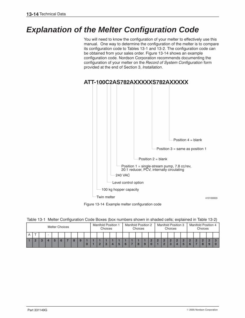
Technical Data13-14
Part 331149G � 2005 Nordson Corporation
Explanation of the Melter Configuration Code You will need to know the configuration of your melter to effectively use thismanual. One way to determine the configuration of the melter is to compareits configuration code to Tables 13-1 and 13-2. The configuration code canbe obtained from your sales order. Figure 13-14 shows an exampleconfiguration code. Nordson Corporation recommends documenting theconfiguration of your melter on the Record of System Configuration formprovided at the end of Section 3, Installation.
410100003
ATT-100C2AS782AXXXXXS782AXXXXX
Twin melter
100 kg hopper capacity
240 VAC
Level control option
Position 1 = single-stream pump, 7.8 cc/rev,20:1 reducer, PCV, internally circulating
Position 2 = blank
Position 3 = same as position 1
Position 4 = blank
Figure 13-14 Example melter configuration code
Table 13-1 Melter Configuration Code Boxes (box numbers shown in shaded cells; explained in Table 13-2)
Melter ChoicesManifold Position 1
ChoicesManifold Position 2
ChoicesManifold Position 3
ChoicesManifold Position 4
Choices
A T -
1 2 3 4 5 6 7 8 9 10
11
12
13
14
15
16
17
18
19
20
21
22
23
24
25
26
27
28
29
30
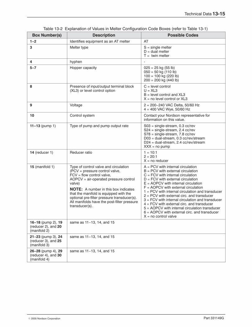
Technical Data 13-15
Part 331149G� 2005 Nordson Corporation
Table 13-2 Explanation of Values in Melter Configuration Code Boxes (refer to Table 13-1)
Box Number(s) Description Possible Codes1−2 Identifies equipment as an AT melter AT
3 Melter type S = single melterD = dual melterT = twin melter
4 hyphen -
5−7 Hopper capacity 025 = 25 kg (55 lb)050 = 50 kg (110 lb)100 = 100 kg (220 lb)200 = 200 kg (440 lb)
8 Presence of input/output terminal block(XL3) or level control option
C = level controlU = XL3B = level control and XL3X = no level control or XL3
9 Voltage 2 = 200−240 VAC Delta, 50/60 Hz4 = 400 VAC Wye, 50/60 Hz
10 Control system Contact your Nordson representative forinformation on this value.
11−13 (pump 1) Type of pump and pump output rate S03 = single-stream, 0.3 cc/revS24 = single-stream, 2.4 cc/revS78 = single-stream, 7.8 cc/revD03 = dual-stream, 0.3 cc/rev/streamD24 = dual-stream, 2.4 cc/rev/streamXXX = no pump
14 (reducer 1) Reducer ratio 1 = 10:12 = 20:1X = no reducer
15 (manifold 1) Type of control valve and circulation(PCV = pressure control valve,FCV = flow control valve,AOPCV = air-operated pressure controlvalve)
NOTE: A number in this box indicatesthat the manifold is equipped with theoptional pre-filter pressure transducer(s).All manifolds have the post-filter pressuretransducer(s).
A = PCV with internal circulationB = PCV with external circulationC = FCV with internal circulationD = FCV with external circulationE = AOPCV with internal circulationF = AOPCV with external circulation1 = PCV with internal circulation and transducer2 = PCV with external circ. and transducer3 = FCV with internal circulation and transducer4 = FCV with external circ. and transducer5 = AOPCV with internal circulation transducer6 = AOPCV with external circ. and transducerX = no control valve
16−18 (pump 2), 19(reducer 2), and 20(manifold 2)
same as 11−13, 14, and 15
21−23 (pump 3), 24(reducer 3), and 25(manifold 3)
same as 11−13, 14, and 15
26−28 (pump 4), 29(reducer 4), and 30(manifold 4)
same as 11−13, 14, and 15

Technical Data13-16
Part 331149G � 2005 Nordson Corporation
DECLARATION of CONFORMITYDeclaration of Conformity Déclaration de Conformité
Konformitätserklärung Declaracion de Conformidad
Dichiarazione di Conformita Conformiteitsverklaring
Product Family: AT Series Hot Melt Adhesive Application SystemProduktgruppe: Schmelzklebstoff−Auftragssystem der Baureihe ATProdotto: Sistema di applicazione per materiale hot melt ATLigne de Produits: Système d’application d’adhésifs thermofusibles de la série ATFamilia de Productos: Sistema de aplicación de materiales termofusibles de la serie ATProductfamilie: Smeltlijm−aanbrengsysteem uit de serie AT
Model Nos: ATS, ATD, ATT
Declaration: The product specified conforms to the following Directives and Standards.Erklärung: Das bezeichnete Produkt entspricht den folgenden Richtlinien und Normen.Dichiarazione: Il prodotto è conforme alle direttive e alle normative seguenti.Déclaration: Le produit spécifié est conforme aux exigences des directives et normes suivantes.Declaración: El producto mencionado satisface las siguientes directivas y estándares.Verklaring: Het gespecifieerde product is conform de volgende richtlijnen en normen.
Directives / Richtlinien / Direttive / Directives / Directivas / Richtlijnen:
98/37/EC (Machinery / Maschinen / macchinari / Machines / maquinaria / Machinerie)
89/336/EEC (Electromagnetic Compatibility / Elektromagnetische Kompatibilität / Compatibilità elettromagnetica / Compatibilité électromagnétique / Compatibilidad electromagnética / Elektromagnetische Compatibiliteit)
Standards / Normen / Normative / Normes / Estándares / Normen:
EN 292 EN 50081−2EN 563 EN 50082−2EN 60204-1
Date: February 1, 2001
Donald J. McLaneSenior Vice President
Nordson Corporation � Westlake, Ohio DOC026 (P/N 1017047A)