Embed Size (px)
Citation preview

C9 and C15 Adhesive Melters
Customer Product ManualPart 1121010_02
Issued 1/13
NORDSON CORPORATION DULUTH, GEORGIA USAwww.nordson.com
This document contains important safety informationBe sure to read and follow all safety information in thisdocument and any other related documentation.

Part 1121010_02 � 2013 Nordson CorporationAll rights reserved
Nordson Corporation welcomes requests for information, comments, and inquiries about its products. General informationabout Nordson can be found on the Internet using the following address: http://www.nordson.com.
Address all correspondence to:
Nordson CorporationAttn: Customer Service11475 Lakefield Drive
Duluth, GA 30097
Notice
This is a Nordson Corporation publication which is protected by copyright. Original copyright date 2012.No�part�of�this�document may be photocopied, reproduced, or translated to another language without the prior written
consent of Nordson�Corporation. The�information�contained in this publication is subject to change without notice.
Trademarks
AccuJet, AeroCharge, Apogee, AquaGuard, Asymtek, Automove, Baitgun, Blue Box, Bowtie, Build‐A‐Part, CanWorks, Century, CF, CleanSleeve,CleanSpray, ColorMax, Color‐on‐Demand, Control�Coat, Coolwave, Cross‐Cut, cScan+, Dage, Dispensejet, DispenseMate, DuraBlue, DuraDrum, Durafiber,
DuraPail, Dura‐Screen, Durasystem, Easy�Coat, Easymove Plus, Ecodry, Econo‐Coat, e.DOT, EFD, Emerald, Encore, ESP, e stylized, ETI‐stylized,Excel 2000, Fibrijet, Fillmaster, FlexiCoat, Flex‐O‐Coat, Flow Sentry, Fluidmove, FoamMelt, FoamMix, Fulfill, GreenUV, HDLV, Heli‐flow, Horizon, Hot Shot,iControl, iDry, iFlow, Isocoil, Isocore, Iso‐Flo, iTRAX, Kinetix, LEAN�CELL, Little�Squirt, LogiComm, Magnastatic, March, Maverick, MEG, Meltex, Microcoat,
Micromark, Micromedics, MicroSet, Millennium, Mini Squirt, Mountaingate, Nordson, Optimum, Package of Values, Pattern View, PermaFlo, PicoDot,Porous�Coat, PowderGrid, Powderware, Precisecoat, PRIMARC, Printplus, Prism, ProBlue, Prodigy, Pro‐Flo, ProLink, Pro‐Meter, Pro‐Stream, RBX, Rhino,Saturn, Saturn with rings, Scoreguard, Seal Sentry, Select�Charge, Select�Coat, Select Cure, Signature, Slautterback, Smart‐Coat, Solder Plus, Spectrum,
Speed‐Coat, SureBead, Sure Coat, Sure‐Max, Sure Wrap, Tracking�Plus, TRAK, Trends, Tribomatic, TrueBlue, TrueCoat, Tubesetter, Ultra, UpTime,u‐TAH, Value Plastics, Vantage, VersaBlue, Versa‐Coat, VersaDrum, VersaPail, Versa‐Screen, Versa‐Spray, VP Quick Fit,
Watermark, and When you expect more. are registered trademarks of Nordson Corporation.
Accubar, Active Nozzle, Advanced Plasma Systems, AeroDeck, AeroWash, AltaBlue, AltaSlot, Alta Spray, Artiste, ATS, Auto‐Flo, AutoScan, Axiom, Best Choice, Blue Series, Bravura, CanPro, Champion, Check Mate, ClassicBlue, Classic IX, Clean�Coat, Cobalt, Controlled Fiberization, Control�Weave,
ContourCoat, CPX, cSelect, Cyclo‐Kinetic, DispensLink, Dry Cure, DuraBraid, DuraCoat, DuraPUR, Easy Clean, EasyOn, EasyPW, Eclipse, e.dot+,E‐Nordson, Equalizer, EquiBead, FillEasy, Fill�Sentry, Flow Coat, Fluxplus, Get Green With Blue, G‐Net, G‐Site, IntelliJet, iON, Iso‐Flex, iTrend,
Lacquer Cure, Maxima, Mesa, MicroFin, MicroMax, Mikros, MiniBlue, MiniEdge, Minimeter, Multifill, MultiScan, Myritex, Nano, NexJet, OmniScan, OptiMix,OptiStroke, Partnership+Plus, PatternJet, PatternPro, PCI, Pinnacle, Plasmod, Powder�Pilot, Powder Port, Powercure, Process Sentry, Pulse Spray,
PURBlue, PURJet, Ready Coat, RediCoat, RollVIA, Royal Blue, Select�Series, Sensomatic, Shaftshield, SheetAire, Smart, Smartfil, SolidBlue, Spectral,SpeedKing, Spray Works, Summit, SureFoam, Sure�Mix, SureSeal, Swirl�Coat, TAH, ThruWave, Trade�Plus, Trilogy, Ultra FoamMix, UltraMax, Ultrasaver,
Ultrasmart, Universal, ValueMate, Versa, Vista, Web Cure, YESTECH, and 2�Rings (Design) are�trademarks of Nordson�Corporation.
Designations and trademarks stated in this document may be brands that, when used by third parties for their own purposes, could lead to violation of the owners' rights.

Table of Contents i
Part 1121010_02� 2013 Nordson Corporation
Table of Contents
Safety 1‐1. . . . . . . . . . . . . . . . . . . . . . . . . . . . . . . . . . . . . . . . . . . . . . . . . . . .Safety Alert Symbols 1‐1. . . . . . . . . . . . . . . . . . . . . . . . . . . . . . . . . . . . . . . .Responsibilities of the Equipment Owner 1‐2. . . . . . . . . . . . . . . . . . . . . . .
Safety Information 1‐2. . . . . . . . . . . . . . . . . . . . . . . . . . . . . . . . . . . . . . . .Instructions, Requirements, and Standards 1‐2. . . . . . . . . . . . . . . . . .User Qualifications 1‐3. . . . . . . . . . . . . . . . . . . . . . . . . . . . . . . . . . . . . . .
Applicable Industry Safety Practices 1‐3. . . . . . . . . . . . . . . . . . . . . . . . . .Intended Use of the Equipment 1‐3. . . . . . . . . . . . . . . . . . . . . . . . . . . . .Instructions and Safety Messages 1‐4. . . . . . . . . . . . . . . . . . . . . . . . . .Installation Practices 1‐4. . . . . . . . . . . . . . . . . . . . . . . . . . . . . . . . . . . . . .Operating Practices 1‐4. . . . . . . . . . . . . . . . . . . . . . . . . . . . . . . . . . . . . .Maintenance and Repair Practices 1‐5. . . . . . . . . . . . . . . . . . . . . . . . .
Equipment Safety Information 1‐5. . . . . . . . . . . . . . . . . . . . . . . . . . . . . . . .Equipment Shutdown 1‐6. . . . . . . . . . . . . . . . . . . . . . . . . . . . . . . . . . . . .
Relieving System Hydraulic Pressure 1‐6. . . . . . . . . . . . . . . . . . . . .De‐energizing the System 1‐6. . . . . . . . . . . . . . . . . . . . . . . . . . . . . . .Disabling the Applicators 1‐6. . . . . . . . . . . . . . . . . . . . . . . . . . . . . . . .
General Safety Warnings and Cautions 1‐7. . . . . . . . . . . . . . . . . . . . . .Other Safety Precautions 1‐10. . . . . . . . . . . . . . . . . . . . . . . . . . . . . . . . . .First Aid 1‐10. . . . . . . . . . . . . . . . . . . . . . . . . . . . . . . . . . . . . . . . . . . . . . . . .
Safety Labels and Tags 1‐11. . . . . . . . . . . . . . . . . . . . . . . . . . . . . . . . . . . . .
Description 2‐1. . . . . . . . . . . . . . . . . . . . . . . . . . . . . . . . . . . . . . . . . . . . . . .Overview 2‐1. . . . . . . . . . . . . . . . . . . . . . . . . . . . . . . . . . . . . . . . . . . . . . . . . .
Product Description 2‐2. . . . . . . . . . . . . . . . . . . . . . . . . . . . . . . . . . . . . .Intended Use 2‐2. . . . . . . . . . . . . . . . . . . . . . . . . . . . . . . . . . . . . . . . . . . .Key Components 2‐3. . . . . . . . . . . . . . . . . . . . . . . . . . . . . . . . . . . . . . . .
Control Panel 2‐4. . . . . . . . . . . . . . . . . . . . . . . . . . . . . . . . . . . . . . . . .Tank 2‐5. . . . . . . . . . . . . . . . . . . . . . . . . . . . . . . . . . . . . . . . . . . . . . . . .Pump 2‐6. . . . . . . . . . . . . . . . . . . . . . . . . . . . . . . . . . . . . . . . . . . . . . . .Manifold 2‐7. . . . . . . . . . . . . . . . . . . . . . . . . . . . . . . . . . . . . . . . . . . . . .Air Pressure Regulator 2‐8. . . . . . . . . . . . . . . . . . . . . . . . . . . . . . . . .Hose Controller 2‐9. . . . . . . . . . . . . . . . . . . . . . . . . . . . . . . . . . . . . . . .

Table of Contentsii
Part 1121010_02 � 2013 Nordson Corporation
Installation 3‐1. . . . . . . . . . . . . . . . . . . . . . . . . . . . . . . . . . . . . . . . . . . . . . . .Experience of Installation Personnel 3‐1. . . . . . . . . . . . . . . . . . . . . . . . .Installation Tasks 3‐2. . . . . . . . . . . . . . . . . . . . . . . . . . . . . . . . . . . . . . . .Installation Requirements 3‐2. . . . . . . . . . . . . . . . . . . . . . . . . . . . . . . . .
Clearances 3‐3. . . . . . . . . . . . . . . . . . . . . . . . . . . . . . . . . . . . . . . . . . .Electrical Power 3‐4. . . . . . . . . . . . . . . . . . . . . . . . . . . . . . . . . . . . . . . . . .Other Considerations 3‐5. . . . . . . . . . . . . . . . . . . . . . . . . . . . . . . . . . . . .Unpack the Melter 3‐6. . . . . . . . . . . . . . . . . . . . . . . . . . . . . . . . . . . . . . . .
Installation Kit Contents 3‐6. . . . . . . . . . . . . . . . . . . . . . . . . . . . . . . . .Customer‐Supplied Materials 3‐6. . . . . . . . . . . . . . . . . . . . . . . . . . . .
Mount the Melter 3‐7. . . . . . . . . . . . . . . . . . . . . . . . . . . . . . . . . . . . . . . . .Melter Brackets 3‐7. . . . . . . . . . . . . . . . . . . . . . . . . . . . . . . . . . . . . . . .
Electrical Installation 3‐8. . . . . . . . . . . . . . . . . . . . . . . . . . . . . . . . . . . . . .Connecting Power Supply Cable Leads 3‐8. . . . . . . . . . . . . . . . . . . .Installing and Connecting the Hose Thermostat 3‐12. . . . . . . . . . . .Connecting a Triggering Device 3‐16. . . . . . . . . . . . . . . . . . . . . . . . . .
Hoses and Applicator Connection 3‐18. . . . . . . . . . . . . . . . . . . . . . . . . . .Connecting the Hoses 3‐19. . . . . . . . . . . . . . . . . . . . . . . . . . . . . . . . . .Connecting the Applicators 3‐21. . . . . . . . . . . . . . . . . . . . . . . . . . . . . .Connecting Air Supply 3‐22. . . . . . . . . . . . . . . . . . . . . . . . . . . . . . . . . .
Operation 4‐1. . . . . . . . . . . . . . . . . . . . . . . . . . . . . . . . . . . . . . . . . . . . . . . . .Fill the Tank 4‐2. . . . . . . . . . . . . . . . . . . . . . . . . . . . . . . . . . . . . . . . . . . . .Start the Melter 4‐3. . . . . . . . . . . . . . . . . . . . . . . . . . . . . . . . . . . . . . . . . .
Setting Up the Pump 4‐3. . . . . . . . . . . . . . . . . . . . . . . . . . . . . . . . . .Stop the Melter 4‐4. . . . . . . . . . . . . . . . . . . . . . . . . . . . . . . . . . . . . . . . . .
Maintenance 5‐1. . . . . . . . . . . . . . . . . . . . . . . . . . . . . . . . . . . . . . . . . . . . . .Operate the System for the First Time 5‐2. . . . . . . . . . . . . . . . . . . . . .Relieve System Pressure 5‐4. . . . . . . . . . . . . . . . . . . . . . . . . . . . . . . . . .
Relieving the System Pressure 5‐4. . . . . . . . . . . . . . . . . . . . . . . . . .Clean the Melter 5‐5. . . . . . . . . . . . . . . . . . . . . . . . . . . . . . . . . . . . . . . . .
Cleaning the Exterior of the Melter 5‐5. . . . . . . . . . . . . . . . . . . . . . . .Clean a Standard Manifold Filter 5‐6. . . . . . . . . . . . . . . . . . . . . . . . . . .
Cleaning the Filter 5‐6. . . . . . . . . . . . . . . . . . . . . . . . . . . . . . . . . . . . .Flush a Standard Manifold Filter 5‐10. . . . . . . . . . . . . . . . . . . . . . . . . . . .
Flushing the Filter 5‐10. . . . . . . . . . . . . . . . . . . . . . . . . . . . . . . . . . . . . .Flush the System 5‐11. . . . . . . . . . . . . . . . . . . . . . . . . . . . . . . . . . . . . . . .
Preparing for Flushing the System 5‐11. . . . . . . . . . . . . . . . . . . . . . . .Flushing the System with Hot Melt Material 5‐14. . . . . . . . . . . . . . . .Flushing the System with a Flushing Material 5‐15. . . . . . . . . . . . . .Flushing the System with Type‐R Fluid 5‐17. . . . . . . . . . . . . . . . . . . .Restoring the Melter to Normal Operation 5‐19. . . . . . . . . . . . . . . . .
Clean the Tank 5‐19. . . . . . . . . . . . . . . . . . . . . . . . . . . . . . . . . . . . . . . . . .Cleaning the Tank when Changing Hot Melt 5‐19. . . . . . . . . . . . . . .Cleaning the Tank with Excessive Char 5‐20. . . . . . . . . . . . . . . . . . .

Table of Contents iii
Part 1121010_02� 2013 Nordson Corporation
Troubleshooting 6‐1. . . . . . . . . . . . . . . . . . . . . . . . . . . . . . . . . . . . . . . . . . .Introduction 6‐1. . . . . . . . . . . . . . . . . . . . . . . . . . . . . . . . . . . . . . . . . . . . . . . .Troubleshooting Guide 6‐2. . . . . . . . . . . . . . . . . . . . . . . . . . . . . . . . . . . . . .
Parts 7‐1. . . . . . . . . . . . . . . . . . . . . . . . . . . . . . . . . . . . . . . . . . . . . . . . . . . . .Using the Illustrated Parts Lists 7‐1. . . . . . . . . . . . . . . . . . . . . . . . . . . . . . .
C9 Melter Assembly 7‐2. . . . . . . . . . . . . . . . . . . . . . . . . . . . . . . . . . . . . .C15 Melter Assembly 7‐4. . . . . . . . . . . . . . . . . . . . . . . . . . . . . . . . . . . . .C9 Melter Chassis Assembly 7‐5. . . . . . . . . . . . . . . . . . . . . . . . . . . . . .C15 Melter Chassis Assembly 7‐8. . . . . . . . . . . . . . . . . . . . . . . . . . . . .C9 and C15 Melter Bulkhead Assembly 7‐10. . . . . . . . . . . . . . . . . . . . .C9 and C15 Melter Rear Assembly Enclosure, 4 and 6 Hose 7‐11. . . . . . . . . . . . . . . . . . . . . . . . . . . . . . . . . . . . . . . . . . . .C9 and C15 Melter Frame Assembly 7‐12. . . . . . . . . . . . . . . . . . . . . . . .C9 and C15 Melter Pump Assembly Cover 7‐13. . . . . . . . . . . . . . . . . . .C9 and C15 Melter Top Assembly Cover 7‐14. . . . . . . . . . . . . . . . . . . .C9 and C15 Melter Thermostat Assembly 7‐15. . . . . . . . . . . . . . . . . . . .C9 and C15 Melter Control Panel 7‐16. . . . . . . . . . . . . . . . . . . . . . . . . . .C9 and C15 Melter Ship with Kit 7‐17. . . . . . . . . . . . . . . . . . . . . . . . . . . .Manifold Assembly 7‐18. . . . . . . . . . . . . . . . . . . . . . . . . . . . . . . . . . . . . . .Manifold Filter 7‐19. . . . . . . . . . . . . . . . . . . . . . . . . . . . . . . . . . . . . . . . . . . .10:1 Piston Pump 7‐20. . . . . . . . . . . . . . . . . . . . . . . . . . . . . . . . . . . . . . . . .
Air Pressure Regulator 7‐23. . . . . . . . . . . . . . . . . . . . . . . . . . . . . . . . . .
Technical Data 8‐1. . . . . . . . . . . . . . . . . . . . . . . . . . . . . . . . . . . . . . . . . . . .Specifications 8‐1. . . . . . . . . . . . . . . . . . . . . . . . . . . . . . . . . . . . . . . . . . . . . .
C9 Melter 8‐1. . . . . . . . . . . . . . . . . . . . . . . . . . . . . . . . . . . . . . . . . . . . . . .C15 Melter 8‐2. . . . . . . . . . . . . . . . . . . . . . . . . . . . . . . . . . . . . . . . . . . . . .Electrical Specifications 8‐3. . . . . . . . . . . . . . . . . . . . . . . . . . . . . . . . . . .Heater Specifications 8‐3. . . . . . . . . . . . . . . . . . . . . . . . . . . . . . . . . . . . .Wiring Diagrams ‐ C9 Melter, 400Y 8‐4. . . . . . . . . . . . . . . . . . . . . . . . .Wiring Diagrams ‐ C15 Melter, 400Y 8‐6. . . . . . . . . . . . . . . . . . . . . . . .C9 Melter Schematics, 400Y 8‐8. . . . . . . . . . . . . . . . . . . . . . . . . . . . . . .C15 Melter Schematics, 400Y 8‐9. . . . . . . . . . . . . . . . . . . . . . . . . . . . . .
EC Declaration of Conformity

Table of Contentsiv
Part 1121010_02 � 2013 Nordson Corporation

Safety 1-1
� 2013 Nordson Corporation Part 1121010_02
Section 1Safety
Read this section before using the equipment. This section containsrecommendations and practices applicable to the safe installation, operation,and maintenance (hereafter referred to as “use”) of the product described inthis document (hereafter referred to as “equipment”). Additional safetyinformation, in the form of task‐specific safety alert messages, appears asappropriate throughout this document.
WARNING! Failure to follow the safety messages, recommendations, andhazard avoidance procedures provided in this document can result inpersonal injury, including death, or damage to equipment or property.
Safety Alert SymbolsThe following safety alert symbol and signal words are used throughout thisdocument to alert the reader to personal safety hazards or to identifyconditions that may result in damage to equipment or property. Comply withall safety information that follows the signal word.
WARNING! Indicates a potentially hazardous situation that, if not avoided,can result in serious personal injury, including death.
CAUTION! Indicates a potentially hazardous situation that, if not avoided,can result in minor or moderate personal injury.
CAUTION! (Used without the safety alert symbol) Indicates a potentiallyhazardous situation that, if not avoided, can result in damage to equipment orproperty.

Safety1-2
� 2013 Nordson CorporationPart 1121010_02
Responsibilities of the Equipment Owner Equipment owners are responsible for managing safety information, ensuringthat all instructions and regulatory requirements for use of the equipment aremet, and for qualifying all potential users.
Safety Information � Research and evaluate safety information from all applicable sources,
including the owner‐specific safety policy, best industry practices,governing regulations, material manufacturer's product information, andthis document.
� Make safety information available to equipment users in accordance with
governing regulations. Contact the authority having jurisdiction forinformation.
� Maintain safety information, including the safety labels affixed to the
equipment, in readable condition.
Instructions, Requirements, and Standards � Ensure that the equipment is used in accordance with the information
provided in this document, governing codes and regulations, and bestindustry practices.
� If applicable, receive approval from your facility's engineering or safety
department, or other similar function within your organization, beforeinstalling or operating the equipment for the first time.
� Provide appropriate emergency and first aid equipment.
� Conduct safety inspections to ensure required practices are being
followed.
� Re‐evaluate safety practices and procedures whenever changes are
made to the process or equipment.

Safety 1-3
� 2013 Nordson Corporation Part 1121010_02
User Qualifications
Equipment owners are responsible for ensuring that users:
� receive safety training appropriate to their job function as directed by
governing regulations and best industry practices
� are familiar with the equipment owner's safety and accident
prevention policies and procedures
� receive equipment‐ and task‐specific training from another qualified
individual
NOTE: Nordson can provide equipment‐specific installation,operation, and maintenance training. Contact your Nordsonrepresentative for information
� possess industry‐ and trade‐specific skills and a level of experience
appropriate to their job function
� are physically capable of performing their job function and are not
under the influence of any substance that degrades their mentalcapacity or physical capabilities
Applicable Industry Safety Practices The following safety practices apply to the use of the equipment in themanner described in this document. The information provided here is notmeant to include all possible safety practices, but represents the best safetypractices for equipment of similar hazard potential used in similar industries.
Intended Use of the Equipment � Use the equipment only for the purposes described and within the limits
specified in this document.
� Do not modify the equipment.
� Do not use incompatible materials or unapproved auxiliary devices.
Contact your Nordson representative if you have any questions onmaterial compatibility or the use of non‐standard auxiliary devices.

Safety1-4
� 2013 Nordson CorporationPart 1121010_02
Instructions and Safety Messages � Read and follow the instructions provided in this document and other
referenced documents.
� Familiarize yourself with the location and meaning of the safety warning
labels and tags affixed to the equipment. Refer to Safety Labels and Tagsat the end of this section.
� If you are unsure of how to use the equipment, contact your Nordson
representative for assistance.
Installation Practices � Install the equipment in accordance with the instructions provided in this
document and in the documentation provided with auxiliary devices.
� Ensure that the equipment is rated for the environment in which it will be
used. This equipment has not been certified for compliance with theATEX directive nor as nonincendive and should not be installed inpotentially explosive environments.
� Ensure that the processing characteristics of the material will not create a
hazardous environment. Refer to the Material Safety Data Sheet (MSDS)for the material.
� If the required installation configuration does not match the installation
instructions, contact your Nordson representative for assistance.
� Position the equipment for safe operation. Observe the requirements for
clearance between the equipment and other objects.
� Install lockable power disconnects to isolate the equipment and all
independently powered auxiliary devices from their power sources.
� Properly ground all equipment. Contact your local building code
enforcement agency for specific requirements.
� Ensure that fuses of the correct type and rating are installed in fused
equipment.
� Contact the authority having jurisdiction to determine the requirement for
installation permits or inspections.
Operating Practices � Familiarize yourself with the location and operation of all safety devices
and indicators.
� Confirm that the equipment, including all safety devices (guards,
interlocks, etc.), is in good working order and that the requiredenvironmental conditions exist.
� Use the personal protective equipment (PPE) specified for each task.
Refer to Equipment Safety Information or the material manufacturer'sinstructions and MSDS for PPE requirements.
� Do not use equipment that is malfunctioning or shows signs of a potential
malfunction.

Safety 1-5
� 2013 Nordson Corporation Part 1121010_02
Maintenance and Repair Practices � Allow only personnel with appropriate training and experience to operate
or service the equipment.
� Perform scheduled maintenance activities at the intervals described in
this document.
� Relieve system hydraulic and pneumatic pressure before servicing the
equipment.
� De‐energize the equipment and all auxiliary devices before servicing the
equipment.
� Use only new Nordson‐authorized refurbished or replacement parts.
� Read and comply with the manufacturer's instructions and the MSDS
supplied with equipment cleaning compounds.
NOTE: MSDSs for cleaning compounds that are sold by Nordson areavailable at www.nordson.com or by calling your Nordson representative.
� Confirm the correct operation of all safety devices before placing the
equipment back into operation.
� Dispose of waste cleaning compounds and residual process materials
according to governing regulations. Refer to the applicable MSDS orcontact the authority having jurisdiction for information.
� Keep equipment safety warning labels clean. Replace worn or damaged
labels.
Equipment Safety Information This equipment safety information is applicable to the following types ofNordson equipment:
� hot melt and cold adhesive application equipment and all related
accessories
� pattern controllers, timers, detection and verification systems, and all
other optional process control devices

Safety1-6
� 2013 Nordson CorporationPart 1121010_02
Equipment Shutdown
To safely complete many of the procedures described in this document, theequipment must first be shut down. The level of shut down required varies bythe type of equipment in use and the procedure being completed. If required, shut down instructions are specified at the start of the procedure.The levels of shut down are:
Relieving System Hydraulic Pressure
Completely relieve system hydraulic pressure before breaking any hydraulicconnection or seal. Refer to the melter‐specific product manual forinstructions on relieving system hydraulic pressure.
De‐energizing the System
Isolate the system (melter, hoses, applicators, and optional devices) from allpower sources before accessing any unprotected high‐voltage wiring orconnection point.
1. Turn off the equipment and all auxiliary devices connected to theequipment (system).
2. To prevent the equipment from being accidentally energized, lock andtag the disconnect switch(es) or circuit breaker(s) that provide inputelectrical power to the equipment and optional devices.
NOTE: Government regulations and industry standards dictate specificrequirements for the isolation of hazardous energy sources. Refer to theappropriate regulation or standard.
Disabling the Applicators
NOTE: Adhesive dispensing applicators are referred to as “guns” in someprevious publications.
All electrical or mechanical devices that provide an activation signal to theapplicators, applicator solenoid valve(s), or the melter pump must bedisabled before work can be performed on or around an applicator that isconnected to a pressurized system.
1. Turn off or disconnect the applicator triggering device (pattern controller,timer, PLC, etc.).
2. Disconnect the input signal wiring to the applicator solenoid valve(s).
3. Reduce the air pressure to the applicator solenoid valve(s) to zero; thenrelieve the residual air pressure between the regulator and the applicator.

Safety 1-7
� 2013 Nordson Corporation Part 1121010_02
General Safety Warnings and Cautions
Table 1-1 contains the general safety warnings and cautions that apply toNordson hot melt and cold adhesive equipment. Review the table andcarefully read all of the warnings or cautions that apply to the type ofequipment described in this manual.
Equipment types are designated in Table 1-1 as follows:
HM = Hot melt (melters, hoses, applicators, etc.)
PC = Process control
CA = Cold adhesive (dispensing pumps, pressurized container, andapplicators)
Table 1-1General Safety Warnings and Cautions
EquipmentType Warning or Caution
HM
WARNING! Hazardous vapors! Before processing any polyurethanereactive (PUR) hot melt or solvent-based material through a compatibleNordson melter, read and comply with the material's MSDS. Ensurethat the material's processing temperature and flashpoints will not beexceeded and that all requirements for safe handling, ventilation, firstaid, and personal protective equipment are met. Failure to comply withMSDS requirements can cause personal injury, including death.
HM
WARNING! Reactive material! Never clean any aluminum componentor flush Nordson equipment with halogenated hydrocarbon fluids.Nordson melters and applicators contain aluminum components thatmay react violently with halogenated hydrocarbons. The use ofhalogenated hydrocarbon compounds in Nordson equipment cancause personal injury, including death.
HM, CAWARNING! System pressurized! Relieve system hydraulic pressurebefore breaking any hydraulic connection or seal. Failure to relieve thesystem hydraulic pressure can result in the uncontrolled release of hotmelt or cold adhesive, causing personal injury.
Continued...

Safety1-8
� 2013 Nordson CorporationPart 1121010_02
Table 1‐1General Safety Warnings and Cautions (contd)
EquipmentType Warning or Caution
HMWARNING! Molten material! Wear eye or face protection, clothing thatprotects exposed skin, and heat‐protective gloves when servicingequipment that contains molten hot melt. Even when solidified, hot meltcan still cause burns. Failure to wear appropriate personal protectiveequipment can result in personal injury.
HM, PC
WARNING! Equipment starts automatically! Remote triggering devicesare used to control automatic hot melt applicators. Before working onor near an operating applicator, disable the applicator's triggeringdevice and remove the air supply to the applicator's solenoid valve(s).Failure to disable the applicator's triggering device and remove thesupply of air to the solenoid valve(s) can result in personal injury.
HM, CA, PC
WARNING! Risk of electrocution! Even when switched off andelectrically isolated at the disconnect switch or circuit breaker, theequipment may still be connected to energized auxiliary devices.De‐energize and electrically isolate all auxiliary devices beforeservicing the equipment. Failure to properly isolate electrical power toauxiliary equipment before servicing the equipment can result inpersonal injury, including death.
HM, CA, PC
WARNING! Risk of fire or explosion! Nordson adhesive equipment isnot rated for use in explosive environments and has not been cerfifiedfor the ATEX directive or as nonincendive. In addition, this equipmentshould not be used with solvent‐based adhesives that can create anexplosive atmosphere when processed. Refer to the MSDS for theadhesive to determine its processing characteristics and limitations.The use of incompatible solvent‐based adhesives or the improperprocessing of solvent‐based adhesives can result in personal injury,including death.
HM, CA, PCWARNING! Allow only personnel with appropriate training andexperience to operate or service the equipment. The use of untrainedor inexperienced personnel to operate or service the equipment canresult in injury, including death, to themselves and others and candamage to the equipment.

Safety 1-9
� 2013 Nordson Corporation Part 1121010_02
Warning or CautionEquipment
Type
HMCAUTION! Hot surfaces! Avoid contact with the hot metal surfaces ofapplicators, hoses, and certain components of the melter. If contactcan not be avoided, wear heat‐protective gloves and clothing whenworking around heated equipment. Failure to avoid contact with hotmetal surfaces can result in personal injury.
HM
CAUTION! Some Nordson melters are specifically designed toprocess polyurethane reactive (PUR) hot melt. Attempting to processPUR in equipment not specifically designed for this purpose candamage the equipment and cause premature reaction of the hot melt. Ifyou are unsure of the equipment's ability to process PUR, contact yourNordson representative for assistance.
HM, CA
CAUTION! Before using any cleaning or flushing compound on or inthe equipment, read and comply with the manufacturer's instructionsand the MSDS supplied with the compound. Some cleaningcompounds can react unpredictably with hot melt or cold adhesive,resulting in damage to the equipment.
HM
CAUTION! Nordson hot melt equipment is factory tested with NordsonType R fluid that contains polyester adipate plasticizer. Certain hot meltmaterials can react with Type R fluid and form a solid gum that canclog the equipment. Before using the equipment, confirm that the hotmelt is compatible with Type R fluid.

Safety1-10
� 2013 Nordson CorporationPart 1121010_02
Other Safety Precautions � Do not use an open flame to heat hot melt system components.
� Check high pressure hoses daily for signs of excessive wear, damage, or
leaks.
� Never point a dispensing handgun at yourself or others.
� Suspend dispensing handguns by their proper suspension point.
First Aid
If molten hot melt comes in contact with your skin:
1. Do NOT attempt to remove the molten hot melt from your skin.
2. Immediately soak the affected area in clean, cold water until the hot melthas cooled.
3. Do NOT attempt to remove the solidified hot melt from your skin.
4. In case of severe burns, treat for shock.
5. Seek expert medical attention immediately. Give the MSDS for the hotmelt to the medical personnel providing treatment.

Safety 1-11
� 2013 Nordson Corporation Part 1121010_02
Safety Labels and TagsTable 1-2 shows the location of the product safety labels affixed to theequipment.
Table 1-2 Safety Labels and Tags
Item Location Description
1 CAUTIONBurn Hazard. Hot Surface.
2 CAUTIONBurn Hazard. Hot Surface.
3 WARNINGHazardous voltage.Disconnect all power supplyconnections before servicing.
Continued...

Safety1-12
� 2013 Nordson CorporationPart 1121010_02
Safety Labels and Tags (contd)
Item Location Description
4 WARNINGBurn Hazard. Hot adhesive. Release pressure before servicing.
5 WARNINGBurn Hazard. Hot adhesive. Release pressure before servicing.

Description 2-1
Part 1121010_02� 2013 Nordson Corporation
Section 2
Description
Overview This manual describes the installation and use of the C9 and C15 adhesivemelters.
With the exception of tank capacity, hose/applicator capacity, and exteriorappearance, all C9 and C15 melters are functionally identical. Theinformation in this manual is standard except where noted.
Figure 2‐1 C9 or C15 melter

Description2-2
Part 1121010_02 � 2013 Nordson Corporation
Product Description
See Figure 2‐2. The C9 and C15 adhesive melters are used in conjunctionwith Nordson hot melt hoses and applicators to create a hot melt applicationsystem.
The melter liquifies solid‐form hot melt and maintains the hot melt at thedesired temperature. When the applicators are activated, the melter pumpsthe liquified hot melt through the hoses and out the applicator nozzles, whereit is commonly applied to the surface of a product.
2
3
1
Figure 2‐2 System components
1. C9 or C15 melter
2. Hot melt hose
3. Hot melt applicator
Intended Use
The C9 and C15 adhesive melters are specifically designed to:
� melt and pump solid‐form hot melt materials that are engineered to be
liquified and extruded at temperatures below 230 �C (450 �F).
� be used with compatible hot melt hoses and applicators that are
manufactured by Nordson Corporation.
� be used in non‐explosive environments

Description 2-3
Part 1121010_02� 2013 Nordson Corporation
Key Components
Figure 2‐3 provides the name and the location of key melter components.
1
2
3
4
5
67
8
Figure 2‐3 Key melter components
1. Tank lid
2. Pump (inside)
3. Air supply port
4. Hose electrical connections
5. Manifold
6. Drain valve and filter
7. Control panel
8. Electrical enclosure door

Description2-4
Part 1121010_02 � 2013 Nordson Corporation
Control Panel
The control panel provides the controls and indicators to program, operate,and monitor the hot melt system.
Figure 2‐4 Control panel components (C9 melter shown here)
1. Power on indicator neon lamp
2. Tank heater power indicator neon lamp
3. Tank temperature control
4. Hose fuse
5. Applicator fuse
6. On/Off switch

Description 2-5
Part 1121010_02� 2013 Nordson Corporation
Tank
The tank melts the adhesive and holds it until it is pumped to the dispensingapplicators. With its aluminum construction, cast‐in heaters, and integralmelting fins, the tank is designed for efficient heat transfer. A strainer in thetank prevents unmelted adhesive from blocking the pump inlet when you fillthe tank. It also prevents pieces of cardboard and other small objects fromentering the pump.
The standard tank comes with a non‐stick coating for easy cleaning.
Refer to General Specifications in Section 8, Technical Data, for the tankstorage capacity and other key information about the tank.
1
2
3
4
Figure 2‐5 Key parts of the tank
1. Tank casting
2. Strainer
3. Melting fins
4. Heater connector
Ready Output Function
The Ready Output function in the C9 and C15 melters is a drycontactclosure that occurs when the tank is heated to its setpoint temperature. Thetank temperature is set through the tank temperature control dial on thecontrol panel within the range of 200°F 400°F. Once the tank reaches theset temperature, the tank thermostat control opens, removing voltage fromthe tank heating element, and energizing the relay coil that provides theReady Output indication to the end user. The end user will determine ifadditional time is needed to fully melt the adhesive in the tank or for otherprocesses in the production line. The Ready Output contact closure is thenmaintained closed until the melter power is turned off at the main switch, orthe tank temperature falls below 180°F.

Description2-6
Part 1121010_02 � 2013 Nordson Corporation
Ready Output Function (contd)
The Ready Output contact closure is accessed at TB3, positions 1 and 2 onthe center frame of the melter. Refer to Connect a Triggering Device inInstallation.
To prevent false Ready Output contact closures, a thermostat is mounted tothe side of the tank and wired into the Ready circuit to ensure that the tank iswithin the proper temperature range.
Pump
The pump transfers melted adhesive from the tank to the dispensingapplicators. The C9 and C15 melters use a 10:1 single‐acting piston pump. Asingle‐acting piston pump delivers adhesive on the down stroke and draws infresh adhesive on the upstroke.
Refer to General Specifications in Section 8, Technical Data, for the pumpdelivery rate and other key information about the pump.
3
1
2
Figure 2‐6 Key parts of a single‐acting pump
1. Air motor
2. Hydraulic section
3. Triggering solenoid valve

Description 2-7
Part 1121010_02� 2013 Nordson Corporation
Manifold
The manifold directs the flow of adhesive from the pump to the filter and fromthe filter to the hoses and applicators.
1
2
3
4
5
Figure 2‐7 Key parts of the manifold
1. Adhesive outlet(pressure relief valve not shown)
2. Adhesive inlet
3. Hose ports
4. Drain valve
5. Manifold filter
Pressure Relief Valve
The pressure relief valve prevents system hydraulic pressure from exceeding103.4 bar (10340 kPa, 1499.69 psi). At this pressure, the valve opens andreturns adhesive to the tank.
Hose Ports
The manifold block has a 45‐degree face for either horizontal or vertical hoserouting. A maximum of six hoses can be connected to the manifold in a C15melter.

Description2-8
Part 1121010_02 � 2013 Nordson Corporation
Drain Valve
The drain valve allows you to drain the tank and manifold or to flush char anddebris from the filter screen. Operators can perform the filter flushingprocedure without removing the filter from the manifold.
Manifold Filter
The manifold filter traps any char or foreign material, keeping it from beingpumped to the hoses and applicators. The melter is shipped with a 0.15‐mm(0.006‐in.) filter screen. Other screen sizes are available.
Air Pressure Regulator
The air pressure regulator allows you to adjust the system air pressure, whichcontrols the hydraulic pressure.
1
2
3
Figure 2‐8 Key parts of the air pressure regulator
1. Regulator
2. Filter
3. Air pressure gauge

Description 2-9
Part 1121010_02� 2013 Nordson Corporation
Hose Controller
The C9 adhesive melter holds up to four hose controllers that arefactory‐installed. The C15 adhesive melter holds up to six hose controllers,out of which five are factory‐installed.
1
2
Figure 2‐9 Hose controller components
1. Hose controller 2. Thermostat cable

Description2-10
Part 1121010_02 � 2013 Nordson Corporation

Installation 3-1
Part 1121010_02� 2013 Nordson Corporation
Section 3
Installation
WARNING! Allow only qualified personnel to perform the following tasks.Follow the safety instructions in this document and all other relateddocumentation.
The melter is shipped from the factory with an installation kit that containscomponents that must be assembled on the melter by the customer. Someadditional materials must also be supplied by the customer to complete theinstallation.
If optional equipment was ordered with the melter, refer to the documentationprovided for installation and operating instructions.
Experience of Installation Personnel
The instructions provided in this section are intended to be used bypersonnel who have experience in the following subjects:
� Hot melt application processes
� Industrial power and control wiring
� Industrial mechanical installation practices
� Basic process control and instrumentation
Before starting the installation, remove the melter from the pallet, locate theinstallation kit, and inspect the melter for damaged and missing parts. Reportany problems to your Nordson representative.

Installation3-2
Part 1121010_02 � 2013 Nordson Corporation
Installation Tasks
The installation sequence is as follows:
1. Verify that the required installation conditions and utilities exist.
2. Unpack and inspect the melter.
3. Mount the melter on the parent machine or support structure.
4. Connect the electrical service.
5. Connect hot melt hoses and applicators.
6. Connect a compressed air supply.
7. Connect the 10:1 pump solenoid valve to a triggering device.
8. Set up the melter to work with the manufacturing process.
9. Flush the melter.
Installation Requirements
Before installing the melter, ensure that the desired installation locationprovides the required clearances, environmental conditions, and utilities.

Installation 3-3
Part 1121010_02� 2013 Nordson Corporation
Clearances
Figure 3‐1 illustrates the minimum clearances that are required between themelter and surrounding objects. Table 3‐1 describes each clearance.
8.00 [203 mm]
Used on 6 hose melters
5.50 [140 mm]
Used on 2 and 4 hose melters
Figure 3‐1 Minimum installation clearances

Installation3-4
Part 1121010_02 � 2013 Nordson Corporation
Clearances (contd)
Table 3‐1 Minimum Installation Clearances
ItemRequired Clearance
C9 C15
A 343.70 mm (13.53 in.) 343.70 mm (13.53 in.)
B 162.93 mm (6.41 in.) 162.93 mm (6.41 in.)
C 203 mm (8.00 in.) 203 mm (8.00 in.)
D 569.84 mm (22.43 in.) 569.84 mm (22.43 in.)
E 229.48 mm (9.03 in.) 229.48 mm (9.03 in.)
F 690 mm (27.17 in.) 835 mm (32.88 in.)
G 239 mm (9.40 in.) 239 mm (9.40 in.)
H 126.56 mm (5.00 in.) 126.56 mm (5.00 in.)
Electrical Power
Before installing the melter, ensure that the melter will not be overloaded andthat the plant's electrical service is rated to handle the power required by themelter and the hoses and applicators that you plan to use.
WARNING! Risk of electrocution! Install a lockable power disconnect switchbetween the electrical service and the melter. Failure to install or properlyuse the disconnect switch when servicing the melter can result in personalinjury, including death.

152 mm(6.0 in.)
Installation 3-5
Part 1121010_02� 2013 Nordson Corporation
Other Considerations
Carefully select the location for the melter and its associated applicators andhoses. Make sure that the location meets the following requirements:
� There is enough room to open the tank lid, open the electrical enclosure,
remove the filter assembly, remove the pump enclosure, and makeelectrical connections for the hoses. For recommended melterclearances, refer to Clearances in this section.
� Maintenance personnel have room to service and repair the melter.
� The mounting surface can support the weight of the melter when the
melter is filled with adhesive.
� The mounting surface is level.
� The mounting surface is raised at least 152 mm (6 in.) for draining
adhesive. See Figure 3‐2.
� The drain valve projects over the edge of the mounting surface.
� The maximum distance between the melter and each applicator is
dictated by the power requirement of each hose.
� The operator must be able to safely reach the control panel and
accurately monitor the control panel indicators.
� The operator must be able to safely observe the level of hot melt inside
the tank.
� The melter must be installed away from areas with strong drafts or where
sudden temperature changes occur.
� The melter must be installed where it will be in conformance with the
ventilation requirements specified in the Material Safety Data Sheet forthe hot melt being used.
Figure 3‐2 Required clearancefor draining and filterflushing

Installation3-6
Part 1121010_02 � 2013 Nordson Corporation
Unpack the Melter
Before starting the installation, remove the melter from the pallet, locate theinstallation kit, and inspect the melter for damaged and missing parts. Reportany problems to your Nordson representative.
Installation Kit Contents
Refer to C9 and C15 Melter Ship with Kit in Section 7, Parts for a list of theinstallation kit contents.
Customer‐Supplied Materials
The following additional materials are also required to install the melter:
� Strain relief (at the disconnect switch box)
� Hardware to secure the melter to the mounting surface

Installation 3-7
Part 1121010_02� 2013 Nordson Corporation
Mount the Melter
Before mounting the melter, ensure that the parent machine or supportstructure is level with respect to the floor, provides an even mounting surface,is not subject to extreme vibration, and is capable of supporting the weight ofthe melter, a full tank of hot melt, and the hoses and applicators.
Refer to Section 8, Technical Data for the weight of the melter. Refer to thetechnical data provided by the hot melt manufacturer for information aboutthe volumetric weight of the hot melt.
Melter Brackets
Secure the melter mounting brackets to the mounting surface.
A
Power or I/O
CONNECTION
[12.70]
.50 TYP
[249.07]
9.81 TYP
[105.73]
4.16 TYP
[9.53]
.375 TYP
[22.23]
.875 TYP
[31.75]
1.25 TYP
Figure 3‐3 Bolt mounting pattern (refer to Table 3‐2)
Table 3‐2 Bolt Mounting Pattern Dimension A
ItemDimension
C9 C15
A 445 mm (17.50 in.) 584 mm (23.0 in.)

Installation3-8
Part 1121010_02 � 2013 Nordson Corporation
Electrical Installation
The C9 and C15 melters are shipped from the factory without an attachedpower cable and without a designated service‐type. To configure the melterto function in your facility, you must connect the power supply cable lead tothe terminal block TB1 in the electrical enclosure of the melter.
Connecting Power Supply Cable Leads
See Figures 3‐4, 3‐5, 3‐6, and 3‐7.
WARNING! Risk of electrocution! Install a lockable power disconnect switchbetween the electrical service and the melter. Failure to install or properlyuse the disconnect switch when servicing the melter can result in personalinjury, including death.
WARNING! All field wire connections are to be made by a qualifiedtechnician.
1. Select a 10 mm2 (8 AWG) power supply cable lead that meets applicableelectrical codes and standards. The maximum amperages of the meltersoperating at a specified voltage are shown in Table�3‐3.
Table 3‐3 Melter Power Requirements
MelterNumber of
Hose/Applicators1‐Phase PowerDraw (Amps)
3‐Phase Power Draw (Amps)
230 VACWith Neutral
240 VACWithout Neutral
C9 4 30 21 22-27
C154 35 25 26-31
6 -- 25 32-38
2. Open the electrical enclosure door.
IMPORTANT: The terminal block TB1 is a two‐part piece that consists ofa plug and base. The terminal block base is attached to a bracket, whichis installed on the melter chassis. The terminal block plug is included inthe ship‐with kit, refer to C9 and C15 Melter Ship with Kit in Parts for a listof the kit contents.
3. Use the terminal block plug provided in the ship-with kit for connectingthe power supply cable leads.
Figure 3‐4 Terminal block TB1installed on the bracket
1. Bracket
2. Terminal block base
3. Terminal block plug

Installation 3-9
Part 1121010_02� 2013 Nordson Corporation
4. Route the power cable through one of the knockout holes on the side ofthe melter, and then to the top of the electrical enclosure. See Figure 3‐5.
Figure 3‐5 Routing the power cable
1. Terminal block plug
2. Power cable
3. Routing the power cable
5. Connect each power supply cable lead into each connector of theterminal block plug.
NOTE: The ground lead comes connected to the ground lug (markedPE/G) located on the terminal block TB1.
Installation3-10
Part 1121010_02 � 2013 Nordson Corporation
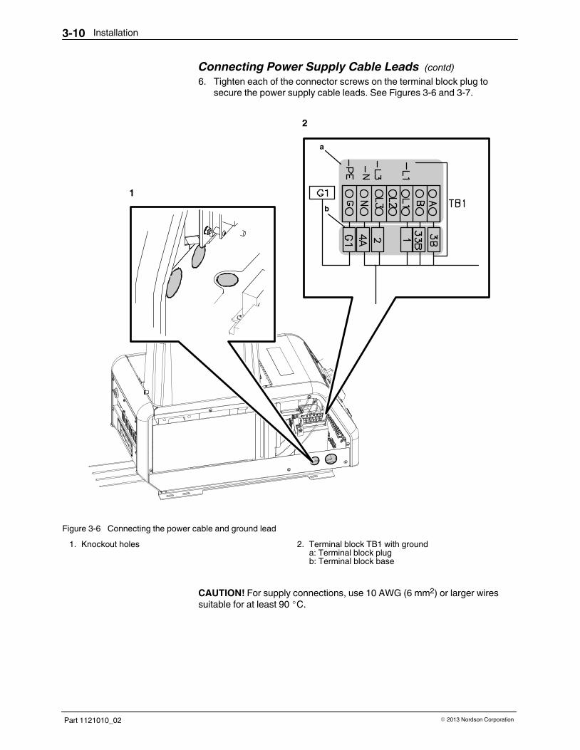
Connecting Power Supply Cable Leads (contd)
6. Tighten each of the connector screws on the terminal block plug tosecure the power supply cable leads. See Figures 3‐6 and 3‐7.
1
2
a
b
Figure 3‐6 Connecting the power cable and ground lead
1. Knockout holes 2. Terminal block TB1 with grounda: Terminal block plugb: Terminal block base
CAUTION! For supply connections, use 10 AWG (6 mm2) or larger wiressuitable for at least 90 �C.

Installation 3-11
Part 1121010_02� 2013 Nordson Corporation
INPUT
INPUT
Figure 3‐7 Power supply location in C9 or C15 melter
1. Terminal block: 230 VAC, 1 2. Terminal block:400/230 VAC, 3
7. Install the plug portion into the terminal block base.
8. Close the electrical enclosure door.

Installation3-12
Part 1121010_02 � 2013 Nordson Corporation
Installing and Connecting the Hose Thermostat
In the C9 adhesive melter, all four hose thermostats are factoryinstalled.Refer to the instructions in Install and Connect the Hose Thermostat onlywhen replacing the hose thermostats in the C9 melter.
In the C15 adhesive melter, five hose thermostats are factoryinstalled. Referto the instructions in Install and Connect the Hose Thermostat only wheninstalling the sixth hose thermostat or replacing any of the hose thermostats.
CAUTION! Do not kink the thermostat cable.
1. Remove the hose controller from the hose box.
2. Carefully uncoil the thermostat.
Figure 3‐8 Uncoiling the thermostat cable
NOTE: Make sure that the electrical enclosure door is open.
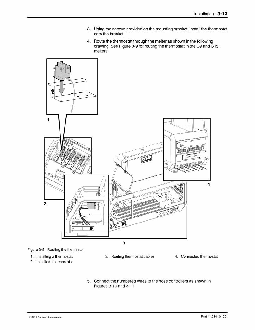
Installation 3-13
Part 1121010_02� 2013 Nordson Corporation
3. Using the screws provided on the mounting bracket, install the thermostatonto the bracket.
4. Route the thermostat through the melter as shown in the followingdrawing. See Figure 3‐9 for routing the thermostat in the C9 and C15melters.
1
2
3
4
Figure 3‐9 Routing the thermistor
1. Installing a thermostat
2. Installed thermostats
3. Routing thermostat cables 4. Connected thermostat
5. Connect the numbered wires to the hose controllers as shown in Figures 3‐10 and 3‐11.

Installation3-14
Part 1121010_02 � 2013 Nordson Corporation
Installing and Connecting the Hose Thermostat (contd)
6. Set the temperature of the hose controller.
Figure 3‐10 Hose controller location in C9, 230 VAC and 400 Y (1 or 3 )

Installation 3-15
Part 1121010_02� 2013 Nordson Corporation
Figure 3‐11 Hose controller location in C15, 230 VAC and 400 Y (1 or 3 )

Installation3-16
Part 1121010_02 � 2013 Nordson Corporation
Connecting a Triggering Device
The following instructions describe how to connect a triggering device for a10:1 single‐acting piston pump.
See Figure 3‐12.
WARNING! Risk of equipment damage, personal injury or death. Install astrain relief to protect wires from being damaged by the edges of theknockout hole.
CAUTION! Electrical components can be easily damaged. Avoid any contactwith electrical components when removing a knockout hole plug.
Follow this procedure to connect a 24 VDC triggering device to the centerframe terminal block.
1. Remove and discard the plug from a knockout hole on either the backside or the bottom of the unit (whichever is most convenient for youroperation) and install a strain relief in the hole. Refer to the following tablefor the appropriate size strain relief.
NOTE: The unit may have several knockout holes. Make sure to route yourtriggering device wires through a larger hole.
Size of Knockout Size of Strain Relief to Install
23 mm (15/16 in.) PG-16 or 1/2-in. trade size
29.5 mm (15/32 in.) PG-21
35 mm (13/8 in.) 1-in. trade size
2. Route the wires from a 24 VDC triggering device through the strain reliefand connect them to terminals 3 and 4 on the terminal block.

Installation 3-17
Part 1121010_02� 2013 Nordson Corporation
CAUTION! Use 0.34�0.25 mm2 (22�24 AWG) wire. Using a different wiresize can cause internal stress-related damage to the unit.
NOTE: Use a multi-wire cable suitable for NEC class 1 remote control andsignaling circuits. To reduce the possibility of electrical shorting, route thecable so that it does not touch nearby electrical components.
3
4
2
1
Figure 3‐12 Connecting a triggering device
1. Wiring from customer's 24 VDCtriggering device
2. Ready Output contact
3. Terminal block 4. Factory installed wiring fromtriggering solenoid valve
3. Close the electrical enclosure door and turn on the local powerdisconnect switch.

Installation3-18
Part 1121010_02 � 2013 Nordson Corporation
Hoses and Applicator Connection
The C9 and C15 melters use specific Nordson hoses and applicators. Thehose/applicator capacity is dependent upon the melter's factoryconfiguration.
NOTE: The C15 melter supports the connection of up to six hose/applicatorpairs.
Maximum hose and applicator power limits
C9 Melter
Hoses 1 4Maximum 960 watts @ 240 VAC per group
Applicators 1 - 4
C15 Melter
Hoses 1 - 6 Maximum 960 watts @ 240 VAC total, 1 or 3
Applicators 1 - 6 Maximum 2400 watts @ 240 VAC total, 1

Installation 3-19
Part 1121010_02� 2013 Nordson Corporation
Connecting the Hoses
Refer to the user's guide provided with each Nordson hose. The guidecontains important information about routing and installing the hose.
NOTE: Save all of the plugs that were removed from the hose ports. A plugwill need to be reinstalled into a hose port if a hose is later removed.
Specific Nordson hoses for use with the C9 and C15 melters
Hose Part Number
HOSE,5/16X4',240V,CLASSIC IX,CAP,W/O CON 1121497
HOSE,5/16X6',240V,CLASSIC IX,CAP,W/O CON 1121498
WARNING! Risk of fire or equipment damage! Before connecting hoses andapplicators to the melter, confirm that the power required by the hoses andthe applicators do not exceed the maximum wattages specified in Section 8,Technical Data.
See Figure 3‐13.
1. Install the hose fittings.
2. Install the thermostat into the hose, and then install the hose onto thefitting.
NOTE: Make sure that the hose is mounted so that the thermostat islocated on the side of the hose. If the thermostat is located on the top orthe bottom of the hose, it will not heat the adhesive properly.
3. Plug the cordset into the melter.

Installation3-20
Part 1121010_02 � 2013 Nordson Corporation
Connecting the Hoses (contd)
2
1
3
Figure 3‐13 Hydraulic component installation

Installation 3-21
Part 1121010_02� 2013 Nordson Corporation
Connecting the Applicators
Refer to the user's guide that is shipped with each applicator for informationabout installing the applicator and connecting a hose to the applicator.
Specific Nordson applicators for use with the C9 and C15 melters
Applicator Part Number
GUN, CBST-STD01-A-CA 350 OOR 1056277
GUN, CBST-2-T'STAT, 59, IA, SPL MTG, 350 1060340
BCM-CBST-STD02ACA7RBXXXXN03 8519260
NOTE: The C9 and C15 melters are shipped with a 100‐mesh (0.15 mm) hotmelt filter installed in the manifold body. Filters with 50‐ and 150‐meshscreens (0.11 mm and 0.07 mm respectively) are also available. Order theappropriate filter based on the smallest nozzle size used in your application.
2
3
1
Figure 3‐14 Connecting an applicator and a hose
1. C9/C15 melter
2. Hot melt hose
3. Hot melt applicator

Installation3-22
Part 1121010_02 � 2013 Nordson Corporation
Connecting Air Supply
CAUTION! Rigidly support the plant air supply before connecting it to the airfilter.
1. Connect a regulated plant air supply to the inlet of the air filter.
NOTE: The air filter inlet is threaded to receive a male G1/4 BSPP fitting.
2. Open the plant air supply to the melter.
3. Turn the pressure regulator adjustment clockwise to set the melter'soperating air pressure (pressure supplied to the pump).
NOTE: To achieve the rated adhesive output of the unit,connect a plantair supply that is capable of providing the maximum air pressure specifiedon the unit. The maximum air pressure is either 4.8 bar (480 kPa, 70 psi)or 6.2 bar (620 kPa, 90 psi), depending upon the type of pump your unithas. To find the maximum air pressure for your unit, check the airpressure tag, which is located next to the inlet air port, above the hoseconnectors.
Figure 3‐15 Connecting the air filter and the plant air supply line

Operation 4-1
Part 1121010_02� 2013 Nordson Corporation
Section 4
Operation
WARNING! Allow only qualified personnel to perform the following tasks.Follow the safety instructions in this document and all other relateddocumentation.
See Figure 4‐1.

Operation4-2
Part 1121010_02 � 2013 Nordson Corporation
Fill the Tank
WARNING! Hot! Risk of burns! Use a scoop to fill the tank with adhesive.Never use your bare hands. Using your bare hands to fill the tank may resultin personal injury.
1. Open the tank lid.
2. Fill the tank with adhesive. Do not overfill.
3. Close the tank lid when you are finished filling the tank.
Figure 4‐1 Tank location
NOTE: When the tank LED on the melter control panel comes on, itindicates that the heater is on.

Operation 4-3
Part 1121010_02� 2013 Nordson Corporation
Start the Melter 1. Turn the melter on.
2. Adjust the temperature according to the adhesive requirements.
Figure 4‐1 Melter controls
1. On/Off switch 2. Tank temperature control
Setting Up the Pump
Energize the 10:1 single‐acting pump before the applicators fire. Followthese pump operating guidelines:
� The application must have a low duty cycle (24 cycles per minute
maximum).
‐ Time to fill the pump (upstroke) is approximately 1.72 sec.
‐ Pump must be energized 200 mSec before opening the applicators.
� One (1) stroke must equal 2.14 cubic inches (35 cubic centimeters).
NOTE: The triggering device (microswitch, photocell, or a timer) must besupplied by the customer.

Operation4-4
Part 1121010_02 � 2013 Nordson Corporation
Stop the Melter 1. Set the air pressure regulator to 0 psi.
2. Turn the melter power switch OFF.
Figure 4‐2 Melter controls
1. On/Off switch

Maintenance 5-1
Part 1121010_02� 2013 Nordson Corporation
Section 5Maintenance
WARNING! Allow only personnel with appropriate training and experience tooperate or service the equipment. The use of untrained or inexperiencedpersonnel to operate or service the equipment can result in injury, includingdeath, to themselves and others, and damage to the equipment.
Table 5‐1 describes the preventive maintenance tasks required to keep C9and C15 melters operating within their specified limits and to preventequipment malfunctions. For information about maintaining optionalequipment that was supplied by Nordson, refer to the instructions providedwith the equipment.
If the melter stops operating or is operating incorrectly, refer toTroubleshooting for information about diagnosing common problems andperforming corrective maintenance.
Table 5‐1 Preventive Maintenance Tasks
Task Frequency Reference
Relieving system pressure Before performing any maintenancetask that requires opening a hydraulicconnection or port
Relieving System Pressure
Clean the exterior of the melter,hoses, and applicators
Daily Cleaning the Melter
Clean the manifold filter Every 40 hours Cleaning a Standard Manifold Filter
Flush the manifold filter Every 8 hours Flushing a Standard Manifold Filter
Cleaning the tank � When changing the type or grade
of hot melt
� When excessive charring occurs
Cleaning the Tank

Maintenance5-2
Part 1121010_02 � 2013 Nordson Corporation
Operate the System for the First Time
Before operating your melter for the first time, flush the system by pumpingadhesive through it to remove trapped air and residue left during factorytesting.
1. Use one of the following methods to prevent accidental applicatortriggering:
� Air‐operated applicators: turn off the operating air
� Electric applicators: turn off the applicator driver
� Hand‐operated applicators: lock the trigger
WARNING! Hot! Risk of burns. Wear heat‐protective clothing, safetygoggles, and heat‐protective gloves.
2. Place a drain pan under each applicator and remove all applicatornozzles.
3. Reduce the pump air pressure to 0 by turning the air pressure regulatorfully counterclockwise.
4. If the melter is not already on, press the power switch to turn the melteron. Allow the melter to reach operating temperature.
5. Clean the manifold filter. Refer to Cleaning a Standard Manifold Filter inthis section.
6. Prepare each applicator in your system for operation as follows:
� Air‐operated applicators: increase the operating air pressure to
2.4 bar (240 kPa,�35 psi)
� Electric applicators: turn on the applicator driver
� Hand‐operated applicators: unlock the trigger

Maintenance 5-3
Part 1121010_02� 2013 Nordson Corporation
WARNING! Trapped air may still be in the hoses and applicators. Shield thearea and operator from splashing adhesive.
7. Trigger the applicators, keeping them open so that no pressure builds up.
NOTE: You may need to adjust the applicator air pressure depending onthe viscosity of the adhesive and the applicator response.
8. Gradually increase the air pressure to the pump by turning the airpressure regulator clockwise. Allow adhesive to flow out of theapplicators until all trapped air, cleaning solution, and impurities areflushed out of the system. If the pump slows noticeably or stops, increasepump air pressure slightly.
9. Stop triggering the applicators.
10. Reduce pump air pressure to 0 by turning the air pressure regulator fullycounterclockwise.
11. Trigger the applicators momentarily to relieve trapped hydraulic pressure.
12. Attach the nozzles to the applicators.
13. Adjust the pump air pressure regulator until the air pressure is at thedesired operating setting. Test adhesive patterns as necessary.
14. Air‐operated applicators only: adjust the applicator air pressure regulatoruntil the air pressure is at the desired operating setting. Test adhesivepatterns as necessary.
15. Refer to the applicator product manual for additional setup information forthe specific applicator.

Maintenance5-4
Part 1121010_02 � 2013 Nordson Corporation
Relieve System Pressure
System pressure must be properly relieved before you can safely proceedwith many of the maintenance, troubleshooting, and repair procedures in thismanual. Follow this procedure whenever you are instructed to relieve systempressure.
Relieving the System Pressure
WARNING! Hot! Risk of burns. Wear heat‐protective clothing, safetygoggles, and heat‐protective gloves. Hot melt material may be releasedunder pressure.
1. Ensure that the melter is at operating temperature.
2. Turn the air pressure regulator fully counterclockwise (no air).
3. Place a container under all applicators and the manifold drain valve.
4. Trigger one or more applicators until adhesive stops flowing.
5. Open the manifold drain valve and allow some adhesive to drain from themanifold.
6. Close the manifold drain valve.
Figure 5‐1 Manifold drain valve

Maintenance 5-5
Part 1121010_02� 2013 Nordson Corporation
Clean the Melter
To prevent components from overheating due to heat build‐up or loss of aircirculation, regularly remove any hot melt that collects on the exterior of themelter, hoses, and applicators.
If hot melt inadvertently spills inside the melter's interior spaces, the sidepanels can be removed in order to clean out the spilled hot melt.
WARNING! Risk of electrocution and fire! Do not clean the melter with adirect stream of water or steam. Use only water or an appropriate,non‐flammable cleaning solution that is applied using a clean cloth. Cleaningthe melter using a direct stream of water or steam or a flammable solvent canresult in property damage and personal injury, including death.
Cleaning the Exterior of the Melter � Apply cleaning compounds using a soft cloth.
� Do not use pointed or sharp tools to clean the exterior surface.

Maintenance5-6
Part 1121010_02 � 2013 Nordson Corporation
Cleaning a Standard Manifold Filter
Use this procedure to clean the manifold filter. Cleaning the filter removesexcess dirt and charred material that can clog the system and cause poorsystem performance.
WARNING! Hot! Risk of burns. Wear heat‐protective clothing, safetygoggles, and heat‐protective gloves. Hot melt material may be releasedunder pressure.
Cleaning the Filter 1. Ensure that the melter is at operating temperature.
2. Flush the manifold filter. Refer to Flushing a Standard Manifold Filter inthis section.
WARNING! System or material pressurized. Relieve pressure. Failure toobserve may result in serious burns.
3. Relieve system pressure. Refer to Relieving System Pressure in thissection.
4. See Figure 5‐2. Loosen the filter using a wrench. A socket‐type wrench isrecommended.
Figure 5‐2 Loosening the filter
Maintenance 5-7
Part 1121010_02� 2013 Nordson Corporation
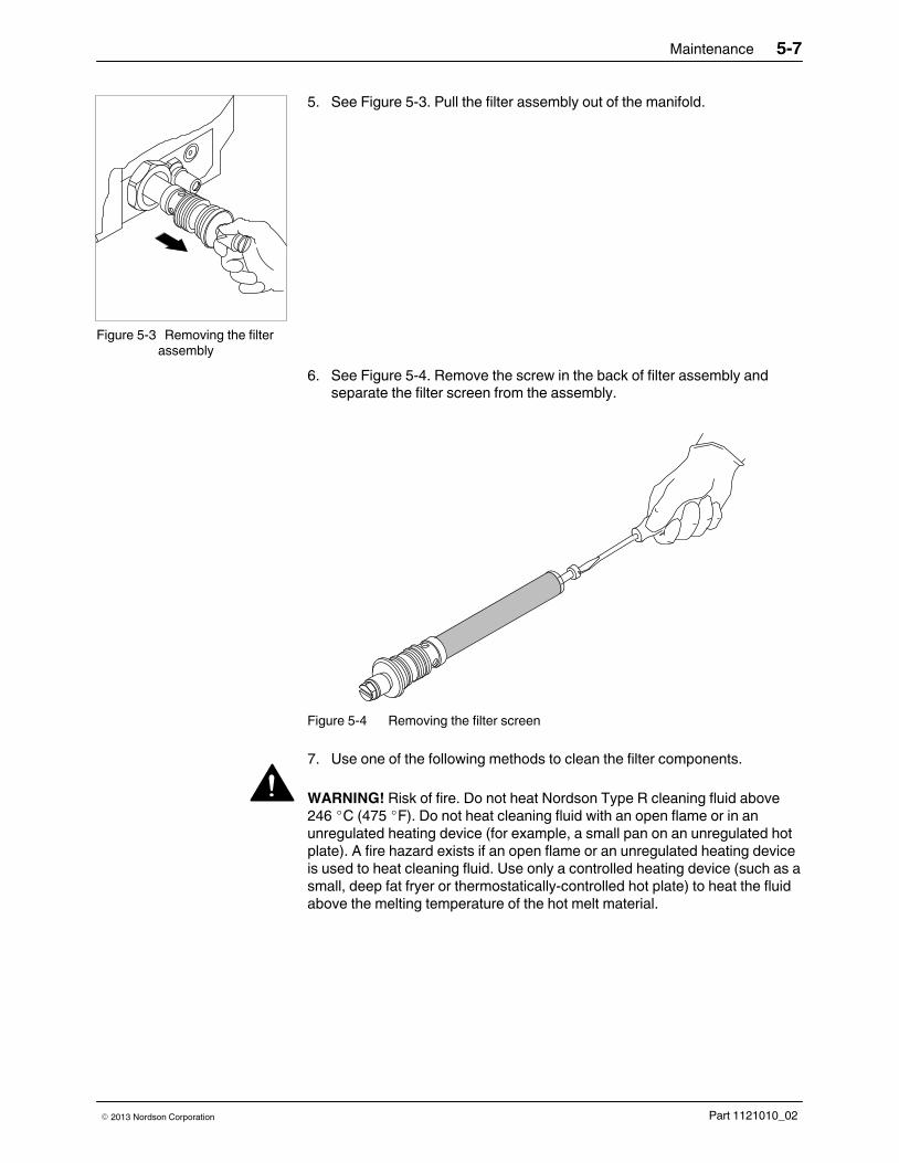
5. See Figure 5‐3. Pull the filter assembly out of the manifold.
Figure 5‐3 Removing the filterassembly
6. See Figure 5‐4. Remove the screw in the back of filter assembly andseparate the filter screen from the assembly.
Figure 5‐4 Removing the filter screen
7. Use one of the following methods to clean the filter components.
WARNING! Risk of fire. Do not heat Nordson Type R cleaning fluid above246 �C (475 �F). Do not heat cleaning fluid with an open flame or in anunregulated heating device (for example, a small pan on an unregulated hotplate). A fire hazard exists if an open flame or an unregulated heating deviceis used to heat cleaning fluid. Use only a controlled heating device (such as asmall, deep fat fryer or thermostatically‐controlled hot plate) to heat the fluidabove the melting temperature of the hot melt material.

Maintenance5-8
Part 1121010_02 � 2013 Nordson Corporation
Cleaning the Filter (contd)
CAUTION! Do not use a metal brush to clean a manifold filter screen. Doingso can damage the screen and prevent the filter from operating properly.
� Place the components (except for the O‐ring) in a container of Type R
cleaning fluid and heat the fluid until it is above the melting point ofthe adhesive. Scrub the components with a fine‐bristled brush.Remember to scrub the filter screen inside and out. Wipe thecomponents with a clean, dry cloth.
� Use a flameless, electric heat applicator or compressed hot air to
heat the components. Wipe the components with a clean, dry cloth.
� Use an ultrasonic cleaner filled with cleaning fluid to soak the
components, then wipe the components with a clean, dry cloth.
8. Inspect the filter screen and O‐ring for damage. A dent or break in thefilter screen mesh means that the screen is damaged beyond repair andshould be replaced.

Maintenance 5-9
Part 1121010_02� 2013 Nordson Corporation
9. See Figure 5‐5. Reassemble the filter.
Figure 5‐5 Assembling the manifold filter
CAUTION! Ensure that the melter is at operating temperature beforereinstalling the filter. Cold material from the filter or manifold walls can causethe filter screen to collapse if it is tightened in a cold system.
10. Ensure that the melter is at operating temperature.
11. Slide the filter assembly into the manifold and tighten it until it isfinger‐tight only.
12. Follow these steps to flush the manifold again:
a. Open the manifold drain valve.
b. Turn the air pressure regulator fully counterclockwise to reduce thepump air pressure to 0.
c. Increase the pump air pressure by turning the air pressure regulatorclockwise until a clean, steady flow of adhesive flows from the drain.Drain approximately 0.25 l (8 oz) of adhesive.
d. Return the pump air pressure to 0.
e. Close the manifold drain valve.
13. Tighten the filter assembly until it seats. Do not overtighten.
14. Return the pump air pressure to the normal operating setting.

Maintenance5-10
Part 1121010_02 � 2013 Nordson Corporation
Flush a Standard Manifold Filter
Use this procedure to flush the manifold filter. Flushing the manifold filterremoves excess dirt and charred material that can clog the system andcause poor system performance.
WARNING! Hot! Risk of burns. Wear heat‐protective clothing, safetygoggles, and heat‐protective gloves. Hot melt material may be releasedunder pressure.
Flushing the Filter 1. Ensure that the melter is at operating temperature.
2. Turn the air pressure regulator fully counterclockwise (no air).
3. Place containers under all applicators and the manifold drain valve.
WARNING! System or material pressurized. Relieve system pressure.Failure to observe may result in serious burns.
4. Trigger the applicators to relieve system pressure.
5. Open the manifold drain valve.
6. Increase the pump air pressure by turning the air pressure regulatorclockwise until a clean, steady flow of adhesive flows from the drain.Allow adhesive to flow until no traces of char are present.
7. Return the air supply pressure to 0.
8. Close the manifold drain valve.
9. Return the air pressure to the normal operating setting.

Maintenance 5-11
Part 1121010_02� 2013 Nordson Corporation
Flush the System
Use this procedure to periodically flush the system with hot melt material, aflushing material, or Type R cleaning fluid. System flushing removes excessdirt and charred material that can clog the system and cause poor systemperformance. You should also flush the system when you switch to a newtype of hot melt material that is incompatible with the old material. If you areunsure whether the materials are compatible, contact your material supplier.
Preparing for Flushing the System 1. Ensure that the melter is at operating temperature.
WARNING! System or material pressurized. Relieve system pressure.Failure to observe may result in serious burns.
2. Relieve system pressure. Refer to Relieving System Pressure in thissection.
3. See Figure 5‐6. Drain the melter by pumping as much hot melt materialfrom the tank as possible using one of the following methods.
Method of Draining Description
Applicator Place a suitable container under eachapplicator nozzle. Remove each nozzle fromits applicator. Return the pump air pressure toits normal setting and pump the hot meltmaterial out through the applicator.
Manifold Pump the hot melt material out through themanifold. Refer to Flushing a StandardManifold Filter in this section.
Hose Disconnect a hose from its applicator. Replacethe dust cover, which was removed duringinstallation, over the hose electrical receptacle.Position the hose over a suitable wastecontainer and secure it. Return the pump airpressure to its normal setting and pump the hotmelt material out through the hose.

Maintenance5-12
Part 1121010_02 � 2013 Nordson Corporation
Preparing for Flushing the System (contd)
Figure 5‐6 Methods of draining the melter
1. Draining through the applicator 2. Draining through the manifold 3. Draining through the hose
4. If you have not already done so, disconnect each hose in the system fromits applicator.
5. Clean each automatic applicator as needed. Refer to the applicatormanual for information on applicator disassembly, cleaning, andrebuilding.

Maintenance 5-13
Part 1121010_02� 2013 Nordson Corporation
6. Refer to Table 5‐2 to determine which method of flushing the system isbest for your operation.
Table 5‐2 Advantages and Disadvantages of System Flushing Procedures
Flushing ProcedureTime Needed(See Note A)
Best Used for...(See Note B)
Advantages andDisadvantages
Using hot melt material About 1 hour Routine cleaning whenthe system is relativelyfree of char
The advantage of thismethod is that it requiresless downtime.However, it is not asthorough as the othertwo methods.
Using a flushing materialrecommended by youradhesive supplier andapproved by yourNordson representative
From 21/2 to 5 hours Occasional cleaningwhen there is some charbuildup
Although this methodrequires more downtime,it�does a good job ofremoving char buildupfrom the system.However, to remove allchar you may need toscrub the tank. You willalso need to purchaseand store flushingmaterial, which mayhave special storageand disposalrequirements.
Using Type R fluid From 3 to 13 hours Thorough cleaning whenthere is significant charbuildup
This procedure is themost thorough way toremove char. You mayalso need to scrub thetank to remove all char.Disadvantages are thatyou cannot flush Type Rfluid through the hoses;accidentally doing socan cause laterdowntime. Type R fluidis expensive but can bereused several times ifthe used fluid is strainedinto a storage container.The fluid is considered aregulated waste.
NOTE A: Time needed varies depending on how much char must be removed.
B: Because operating conditions vary from plant to plant, you may find that more or less frequent flushing isrequired.

Maintenance5-14
Part 1121010_02 � 2013 Nordson Corporation
Preparing for Flushing the System (contd)
7. Refer to the appropriate procedure for the flushing method you haveselected:
� Flush the System with Hot Melt Material
� Flush the System with a Flushing Material
� Flush the System with Type R Fluid
Flushing the System with Hot Melt Material 1. Before beginning this procedure, first complete the procedure Prepare for
Flushing the System earlier in this section.
NOTE: This procedure describes how to flush all hoses at once.However, for maximum cleaning of badly charred hoes, use thisprocedure and flush each hose one at a time.
2. If you have not already done so, secure the free end of each hose to acontainer that will be used to collect the hot melt material.
3. Using a metal or plastic scoop, fill the tank to within 25 mm (1 in.) of thetop with fresh, clean hot melt material.
4. Allow the melter to reach operating temperature.
5. Gradually increase pump air pressure by turning the air pressureregulator clockwise to pump hot melt material through the system until thematerial is free of char and contaminants.
6. Decrease pump air pressure to 0 by turning the valve fullycounterclockwise.
CAUTION! Using a metal brush or scraper can damage tanks with non-stickcoating. Use a stiff‐bristled, nonmetal brush when cleaning a tank withnon‐stick coating.
7. Use a stiff‐bristled, non‐metal brush or similar tool to scrub the tank ordislodge as much char and debris as possible. Do not use a metal brushor scraper on tanks with non-stick coating.
NOTE: If this procedure does not remove all the charred material, youmay need to replace the tank.
8. Clean the manifold filter. Refer to Cleaning a Standard Manifold Filter inthis section.
9. Go to the procedure Restore the Melter to Normal Operation in thissection.

Maintenance 5-15
Part 1121010_02� 2013 Nordson Corporation
Flushing the System with a Flushing Material
WARNING! Use the flushing material at the manufacturer's recommendedtemperature, which will be below the hot melt material's flash point. Failure toobserve this warning can cause a fire.
WARNING! Never flush your system or clean any aluminum componentswith halogenated hydrocarbon cleaning solutions. These cleaning solutionsare extremely dangerous when used to clean aluminum components in apressurized fluid system.
CAUTION! Do not use this procedure to flush your system with Type R fluid.This procedure instructs you to pump flushing material through the hoses.Flushing Type R fluid through hoses can cause large pieces of char to breakoff and clog the nozzles during later operation. If you plan to use Type R fluidto flush your system, refer to the procedure, Flush the System with Type RFluid in this section.
CAUTION! Certain flushing materials can damage seals and O‐rings,resulting in poor pump performance. Be sure that the flushing material youuse has been approved by your Nordson representative. To determine thebest flushing material to use, contact your adhesive supplier.
1. Before beginning this procedure, first complete the procedure Prepare forFlushing the System earlier in this section.
NOTE: This procedure describes how to flush all hoses at once.However, for maximum cleaning of badly charred hoses, use thisprocedure and flush each hose one at a time.
2. If you have not already done so, secure the free end of each hose to acontainer that will be used to collect the hot melt material.
3. Set the tank and hose temperature to the recommended temperature ofthe flushing material.

Maintenance5-16
Part 1121010_02 � 2013 Nordson Corporation
Flushing the System with a Flushing Material (contd)
4. Pour the flushing material into the empty tank to within 25 mm (1 in.) ofthe top of the tank.
5. When the melter reaches the preset temperature, gradually increasepump air pressure by turning the air pressure regulator clockwise andpump material through the system until the flushing material starts tocome out.
6. Decrease pump air pressure to 0 by turning the valve fullycounterclockwise.
7. Allow the remaining material to drain from the hoses.
8. Remove the hoses from the collection container, place them over thetank, and secure them.
9. Slowly increase pump pressure by turning the air pressure regulatorclockwise so the flushing material circulates through the system withoutsplashing out of the tank. Allow the system to circulate for one andone‐half to four hours.
10. Decrease pump air pressure to 0 by turning the air pressure regulatorfully counterclockwise and wait for material to finish draining from thehoses.
11. Remove the hoses from the tank, secure them over a waste containerand drain the flushing material from the tank into the container.

Maintenance 5-17
Part 1121010_02� 2013 Nordson Corporation
CAUTION! Using a metal brush or scraper can damage tanks with non-stickcoating. Use a stiff‐bristled, nonmetal brush when cleaning a tank withnon‐stick coating.
12. Use a stiff‐bristled, nonmetal brush or similar tool to scrub the tank ordislodge as much char and debris as possible. Do not use a metal brushor scraper on tanks with non-stick coating.
NOTE: If this procedure does not remove all the charred material, youmay need to replace the tank.
13. Using a metal or plastic scoop, fill the tank to within 25 mm (1 in.) of thetop with fresh, clean hot melt material.
14. Set the temperature of the tank to the lowest temperature that theadhesive can be pumped at.
15. Wait for the melter to reach the preset temperature, then drain 3/4 of theadhesive through the hoses into the waste container.
16. After you have drained 3/4 of the material, reduce the pump air pressureto 0 by turning the air pressure regulator fully counterclockwise.
17. Place a container under the manifold drain valve, open the valve, anddrain the remaining adhesive.
18. Clean the manifold filter. Refer to Cleaning a Standard Manifold Filter inthis section.
19. Go to the procedure Restore the melter to Normal Operation in thissection.
20. Place a container under the manifold drain valve, open the valve, anddrain the remaining adhesive.
Flushing the System with Type‐R Fluid 1. Before beginning this procedure, first complete the procedure Prepare for
Flushing the System earlier in this section.
2. Set the tank temperature 14-17 �C (25-30 �F) higher than therecommended application temperature of the adhesive.
3. Pour Type R fluid into the empty tank to within 25 mm (1 in.) of the top ofthe tank.
4. Use a clean paint brush or similar tool to apply fluid to areas notsubmerged in the fluid.
5. Allow the fluid to heat in the tank for 2-12 hours.
6. As needed, use a wooden or plastic strainer to skim off the char andadhesive that floats to the top of the tank.

Maintenance5-18
Part 1121010_02 � 2013 Nordson Corporation
Flushing the System with Type‐R Fluid (contd)
CAUTION! Do not pump Type R fluid through hoses. Fluid absorbed by charin the hoses may leach out or cause large pieces of char to break off andclog a nozzle during later operation.
7. Place a container under the manifold drain valve, open the valve, anddrain the fluid from the manifold.
NOTE: You can reuse the fluid if you place a strainer on the top of thecontainer used to collect it.
8. Close the manifold drain valve.
9. Using a metal or plastic scoop, place several pounds of fresh, clean hotmelt material into the empty tank.
10. Set the temperature of the tank and hoses to the lowest temperature thatthe adhesive can be pumped at.
11. Secure the free end of the hose to a container that will be used to collectthe hot melt material.
12. When the tank and hoses reach their setpoint temperatures, graduallyincrease pump pressure by turning the air pressure regulator clockwise topump adhesive through the hoses.
13. Continue pumping adhesive into the waste container until a clean, steadystream of material flows from each hose.
14. When material has finished draining, reduce the pump air pressure to 0by turning the valve fully counterclockwise.
15. Clean the manifold filter. Refer to Cleaning a Standard Manifold Filter inthis section.
16. Go to the procedure Restore the melter to Normal Operation in thissection.
17. Secure the free end of the hose to a container that will be used to collectthe hot melt material.

Maintenance 5-19
Part 1121010_02� 2013 Nordson Corporation
Restoring the Melter to Normal Operation
After flushing your system with hot melt material, a flushing material, or Type R fluid, follow this procedure to restore your melter to normal operation.
1. Disconnect and lock out electrical power to the melter.
2. Reconnect each applicator to its hose both electrically and mechanically.Refer to Connecting Hoses and Applicators in Section�3, Installation.
3. Remove the lock‐out and restore power to the melter.
4. If you have changed the melter's temperature setpoints or if therecommended operating temperature of the new adhesive is differentfrom the previous adhesive, reprogram the temperature settings.
5. Use a metal or plastic scoop to fill the tank with adhesive. Refer to Fillingthe Tank in Section 4, Operation.
6. Return the air supply pressure to the normal operating setting.
7. Resume normal operation.
Clean the Tank
To avoid the problems that can occur when different hot melt materials aremixed or when hot melt char forms in the tank, clean the tank when:
� changing to a different type of hot melt
� excessive char builds up inside the tank
NOTE: The tank cleaning procedures provided in this section require that anappropriate flushing material be used. The flushing material should be compatiblewith both the previous adhesive and the new adhesive, if applicable.
Cleaning the Tank when Changing Hot Melt 1. Operate the melter normally until the tank is empty.
2. Close the air supply to the melter.
3. Allow the melter to heat or cool to the temperature recommended by themanufacturer of the flushing material.
4. While wearing the appropriate protective equipment, wipe any residualhot melt from the inside of the tank.
5. Add the appropriate type and quantity of flushing material to the tank.
6. Open the air supply to the melter.
7. Pump all of the flushing material from the tank and through the hoses andapplicators.
8. Return the melter to normal operation and pump a minimum of one tankvolume of fresh hot melt through the tank, hoses, and applicators.

Maintenance5-20
Part 1121010_02 � 2013 Nordson Corporation
Cleaning the Tank with Excessive Char 1. Remove the old hot melt and loose char as follows:
a. Operate the melter normally until the tank is empty.
b. Close the air supply to the melter.
c. Allow the melter to heat or cool to the temperature recommended bythe manufacturer of the flushing material.
d. While wearing the appropriate protective equipment, wipe anyresidual hot melt and loose char from the inside of the tank.
e. Remove the tank strainer, clean it with an appropriate flushingmaterial, and then reinstall it.
2. Add the appropriate type and quantity of hot melt solvent to the tank.
3. Disconnect a hose from a applicator and direct the hose into a wastecontainer.
4. Close the pressure control valve by turning the valve all the wayclockwise.
WARNING! Risk of burns! Wear protective equipment and use caution whenpumping hot material into a waste container.
5. Open the air supply to the melter.
6. When the tank is empty, close the air supply to the melter.
7. Fill the tank with fresh hot melt.
8. Repeat steps 5 and 6 to pump all of the hot melt out of the tank.
9. Reconnect the disconnected hose to its applicator.
10. Clean the filter. Refer to Cleaning a Standard Manifold Filter in thissection.
11. Fill the tank with fresh hot melt and then purge all of the hoses andapplicators with the fresh hot melt.
12. Restore the system to normal operation.

Troubleshooting 6-1
Part 1121010_02� 2013 Nordson Corporation
Section 6
Troubleshooting
WARNING! Allow only qualified personnel to perform the following tasks.Follow the safety instructions in this document and all other relateddocumentation.
Introduction This section contains troubleshooting procedures. These procedures coveronly the most common problems that you may encounter. If you cannotsolve the problem with the information given here, contact your local Nordsonrepresentative for help.

Troubleshooting6-2
Part 1121010_02 � 2013 Nordson Corporation
Troubleshooting Guide Troubleshooting tables list typical applicator faults, their probable causes,and corrective actions.
NOTE: The Nordson Hose/Applicator Diagnostic Device enables preciseand complete heater and RTD troubleshooting for RTD controlled FP‐200applicators. The device enables you to quickly accomplish applicator RTDand heater troubleshooting without removing the applicators from the hoses.Contact your Nordson representative for more information.
Problem Possible Cause Corrective Action
1. No adhesive outputfrom one or moreapplicators
Applicator nozzles may be clogged Clean the applicator nozzles.
Pump may not be energized Provide 24 VDC signal to pumpsolenoid.
Tank may be empty Fill the tank with adhesive.
Filter may be clogged Clean the filter.
2. No Ready outputsignal
Loose/disconnected wires Reconnect the loose wires.
Tank may not be at settemperature yet. Tank temperaturecontrol must open once.
Wait for the tank to heat to set pointtemperature.
Faulty relay or relay not seated insocket
Verify that the relays are fully seatedin sockets. Verify 240 VAC is appliedto relay coil.
Faulty or disconnected 200°Fthermostat
Replace or connect the thermostat.
3. Tank not heatingenough
Check for open heating element ordisconnected wires
Tank heater resistance should beapproximately 19 ohms (C9) or 14 ohms (C15). Connect the wires.
Check for correct set point on tanktemperature control
Adjust the tank set point temperature.
Faulty tank temperature control Replace the tank temperature control.
4. Tank overheating/toohot
Check for tank heater wiresshorted to ground
Resistance from the tank heater wiresto ground should be ≥ 1 MΩ.
Faulty or mis‐wired tanktemperature control
Verify the wiring per appropriatewiring diagram.
5. Hoses not heatingenough
Check for open heating element ordisconnected wires
Most Classic hose heater resistancesare in the range 95 ohms to 590 ohms.
Check for open hose fuse(s) Replace the fuse if it is open.
Faulty, disconnected, or mis‐wiredhose temperature control
Replace or reconnect hosetemperature control. Verify wiring perappropriate wiring diagram.
Check for correct set point on hosetemperature control
Adjust the hose temperature set point.

Troubleshooting 6-3
Part 1121010_02� 2013 Nordson Corporation
Problem Possible Cause Corrective Action
6. Hosesoverheating/too hot
Check that the hose temperaturecontrol bulb is inserted fully intohose
Fully insert the control bulb into thehose.
Check for the correct set point onthe hose temperature control
Adjust the hose temperature set point.
Faulty hose temperature controlwill not open
Replace the hose temperaturecontrol.
Check for hose heater wiresshorted to ground
Resistance from the hose heaterwires to ground should be ≥ 1 MΩ.
7. Applicators notheating enough
Check for open heating element ordisconnected wires
Most applicator heater resistancesare in the range 106 ohms to 1058 ohms.
Check for open applicator fuse(s) Replace the fuse if it is open
Check for correct applicatorthermostat value
Match the applicator thermostat valueto application requirements
Faulty, disconnected, or mis‐wiredapplicator thermostat
Replace or reconnect the applicatorthermostat
8. Applicatoroverheating/too hot
Check for correct applicatorthermostat value
Match applicator thermostat value toapplication requirements.
Check for heater wires shorted toground in applicator body
Resistance from applicator heaterwires to ground should be ≥ 1 MΩ.
Faulty applicator thermostat will notopen
Replace the applicator thermostat.
9. Neon lamp(s) offwhen it should be on
Power is removed from melter inputterminal block
Restore power to the melter.
Faulty neon lamp Replace the faulty neon lamp.
Check for disconnected wires tolamps
Connect the loose wires.

Troubleshooting6-4
Part 1121010_02 � 2013 Nordson Corporation
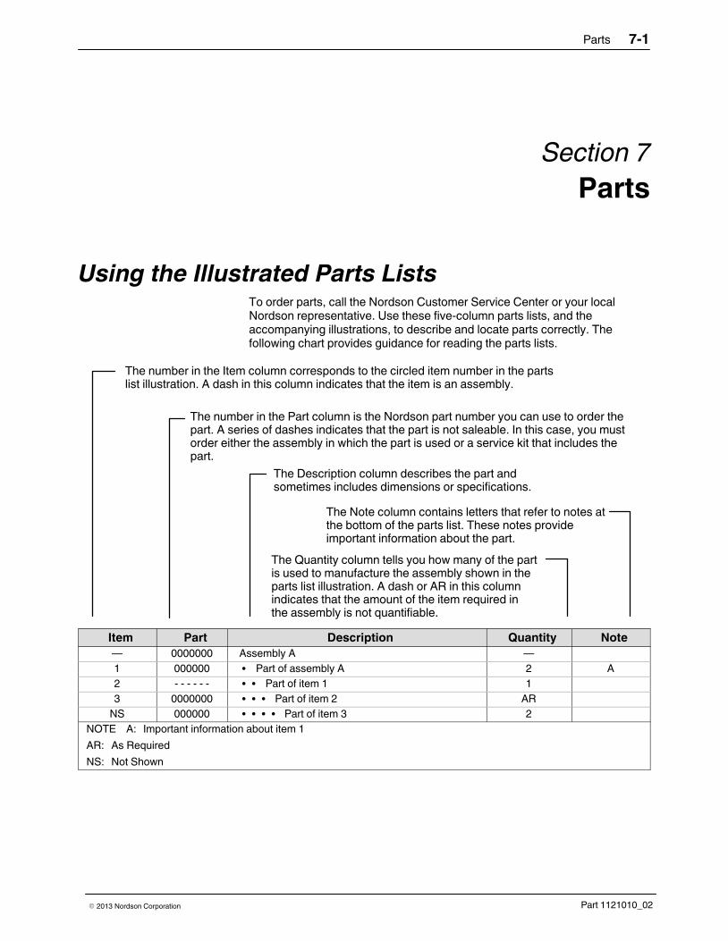
Parts 7-1
Part 1121010_02� 2013 Nordson Corporation
Section 7
Parts
Using the Illustrated Parts Lists To order parts, call the Nordson Customer Service Center or your localNordson representative. Use these five‐column parts lists, and theaccompanying illustrations, to describe and locate parts correctly. Thefollowing chart provides guidance for reading the parts lists.
The number in the Item column corresponds to the circled item number in the partslist illustration. A dash in this column indicates that the item is an assembly.
The number in the Part column is the Nordson part number you can use to order thepart. A series of dashes indicates that the part is not saleable. In this case, you mustorder either the assembly in which the part is used or a service kit that includes thepart.
The Description column describes the part andsometimes includes dimensions or specifications.
The Note column contains letters that refer to notes atthe bottom of the parts list. These notes provideimportant information about the part.
The Quantity column tells you how many of the partis used to manufacture the assembly shown in theparts list illustration. A dash or AR in this columnindicates that the amount of the item required inthe assembly is not quantifiable.
Item Part Description Quantity Note
— 0000000 Assembly A —
1 000000 � Part of assembly A 2 A
2 ‐ ‐ ‐ ‐ ‐ ‐ � � Part of item 1 1
3 0000000 � � � Part of item 2 AR
NS 000000 � � � � Part of item 3 2
NOTE A: Important information about item 1
AR: As Required
NS: Not Shown
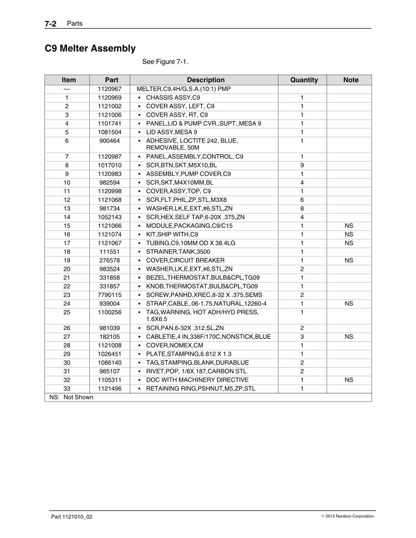
Parts7-2
Part 1121010_02 � 2013 Nordson Corporation
C9 Melter Assembly
See Figure 7‐1.
Item Part Description Quantity Note
— 1120967 MELTER,C9,4H/G,S.A.(10:1) PMP
1 1120969 � CHASSIS ASSY,C9 1
2 1121002 � COVER ASSY, LEFT, C9 1
3 1121006 � COVER ASSY, RT, C9 1
4 1101741 � PANEL,LID & PUMP CVR.,SUPT.,MESA 9 1
5 1081504 � LID ASSY,MESA 9 1
6 900464 � ADHESIVE, LOCTITE 242, BLUE,REMOVABLE, 50M
1
7 1120987 � PANEL,ASSEMBLY,CONTROL, C9 1
8 1017010 � SCR,BTN,SKT,M5X10,BL 9
9 1120983 � ASSEMBLY,PUMP COVER,C9 1
10 982594 � SCR,SKT,M4X10MM,BL 4
11 1120998 � COVER,ASSY,TOP, C9 1
12 1121068 � SCR,FLT,PHIL,ZP,STL,M3X8 6
13 981734 � WASHER,LK,E,EXT,#6,STL,ZN 8
14 1052143 � SCR,HEX,SELF TAP,6-20X .375,ZN 4
15 1121066 � MODULE,PACKAGING,C9/C15 1 NS
16 1121074 � KIT,SHIP WITH,C9 1 NS
17 1121067 � TUBING,C9,10MM OD X 38.4LG 1 NS
18 111551 � STRAINER,TANK,3500 1
19 276578 � COVER,CIRCUIT BREAKER 1 NS
20 983524 � WASHER,LK,E,EXT,#6,STL,ZN 2
21 331858 � BEZEL,THERMOSTAT,BULB&CPL,TG09 1
22 331857 � KNOB,THERMOSTAT,BULB&CPL,TG09 1
23 7790115 � SCREW,PANHD,XREC,8-32 X .375,SEMS 2
24 939004 � STRAP,CABLE,.06-1.75,NATURAL,12260-4 1 NS
25 1100256 � TAG,WARNING, HOT ADH/HYD PRESS,1.6X6.5
1
26 981039 � SCR,PAN,6-32X .312,SL,ZN 2
27 182105 � CABLETIE,4 IN,338F/170C,NONSTICK,BLUE 3 NS
28 1121008 � COVER,NOMEX,CM 1
29 1026451 � PLATE,STAMPING,6.812 X 1.3 1
30 1086140 � TAG,STAMPING,BLANK,DURABLUE 2
31 985107 � RIVET,POP, 1/8X.187,CARBON STL 2
32 1105311 � DOC WITH MACHINERY DIRECTIVE 1 NS
33 1121496 � RETAINING RING,PSHNUT,M5,ZP,STL 1
NS: Not Shown

Parts 7-3
Part 1121010_02� 2013 Nordson Corporation
2X
2X
33
9
4
10
5
25
301
3129
20
26
7
22 12
2
3
4X
12
2X11
62X
18
21
2X
33
9X8
12 2X
13
33
33
2X
144X
232X28
24
Figure 7‐1 Melter assembly parts

Parts7-4
Part 1121010_02 � 2013 Nordson Corporation
C15 Melter Assembly
See Figure 7‐1.
Item Part Description Quantity Note
— 1120968 MELTER,C15,6H/G,S.A.(10:1) PMP 1
1 1120970 � CHASSIS ASSY,C15 1
2 1121000 � COVER ASSY, LEFT, C15 1
3 1121004 � COVER ASSY, RT, C15 1
4 1101742 � PANEL, LID & PUMP CVR.,SUPT, MESA 14 1
5 1081275 � LID ASSY, MESA, 14 LITER 1
6 900464 � ADHESIVE, LOCTITE 242, BLUE,REMOVABLE,50M
1
7 1120988 � PANEL, ASSEMBLY, CONTROL, C15 1
8 1017010 � SCR,BTN,SKT,M5X10,BL 9
9 1120985 � ASSEMBLY, PUMP COVER, C15 1
10 982594 � SCR, SKT, M4X10 MM, BL 4
11 1121052 � COVER, ASSY, TOP, C9 1
12 1121263 � SCR,PAN,PHIL,SS,M3X10,SEALING 6
13 288221 � GASKET,.354X.216,MPL,3000V 1
14 1040011 � NUT,HEX,W/EXT TOOTH WASHER, M4 4
15 1121066 � MODULE, PACKAGING, C9/C15 1
16 1121009 � KIT, SHIP WITH, C15 1
17 1090068 � TUBING, MESA 14, 10MM OD X 47LG 1
18 100353 � STRAINER, TANK, 3700, FULL, MPL 1
19 100352 � STRAINER, TANK, 3700, MPL 1 NS
20 983524 � WASHER, LK, E, EXT, #6, STL, ZN 2
21 331858 � BEZEL, THERMOSTAT, BULB & CPL, TG09 1
22 331857 � KNOB, THERMOSTAT, BULB & CPL, TG09 1
23 7790115 � SCREW, PAN HD, XREC, 832 X .375, SEMS 2
24 276578 � COVER,CIRCUIT BREAKER 1 NS
25 1100256 � TAG, WARNING, HOT ADH/HYD PRESS,1.6X6.5
1
26 981039 � SCR, PAN, 632X .312, SL, ZN 2
27 182105 � CABLETIE, 4 IN, 338F/170C,NONSTICK,BLUE
3 NS
28 939004 � STRAP,CABLE,.06-1.75,NATURAL,12260-4 1 NS
29 1026451 � PLATE, STAMPING, 6.812 X 1.3 1
30 1086140 � TAG, STAMPING, BLANK, DURABLUE 2
31 985107 � RIVET, POP, 1/8X.187, CARBON STL 2
32 1105311 � DOC WITH MACHINERY DIRECTIVE 1 NS
33 1121496 � RETAINING RING,PSHNUT,M5,ZP,STL 2
34 247006 � CLAMP,HOSE,.673-.795 OD 1 NS
NS: Not Shown

Parts 7-5
Part 1121010_02� 2013 Nordson Corporation
C9 Melter Chassis Assembly
See Figures 7‐2, 7‐3, and 7‐4.
Item Part Description Quantity Note
— 1120969 CHASSIS ASSY,C9
1 1120974 � BASE, C9 1
2 1120971 � FRAME ASSY.,C9/C15 1
3 — � Reserved
4 1121516 � BRACKET,C9/C15,TB1 1
5 1059740 � TBACCY,DIN,ENDBRACKET,35MM,GRAY 2
7 338368 � SCR,PAN,XRECES,M3,5MM,STL,ZINC 8
8 983403 � WASHER,LK,M,SPT,M4,STL,ZN 1
9 982308 � SCR,PAN,REC,M4X10,ZN 1
10 983401 � WASHER,LK,M,SPT,M5,STL,ZN 2
11 984706 � NUT,HEX,M5,STL,ZN 2
12 240674 � TAG,GROUND 3
13 230079 � CLAMP,BULB,THERMOSTAT 1
14 1120981 � ENCLOSURE,ASSY,REAR,4 HOSE,C9 1
15 1059005 � THERMOSTAT,ASSY,C.O.R,500 F,21.00LG 1
16 308954 � THERMOSTAT,200400F,BULB & CPL 1
17 109904 � GASKET,TANK,3500 1
18 983035 � WASHER,FLT,M,REG,M5,STL,ZN 2
19 1120980 � DIN RAIL,35MMX7.5MMX74MM 1
21 1089184 � COVER,TANK,MESA 9 1
22 109906 � GASKET,TANK COVER,3500 1
23 900298 � COMPOUND,HEAT SINK,5 OZ TUBE,11281 1
24 1120201 � LUBRICANT,ORING,NSFH1,10 ML TUBE 1
25 1090328 � STANDOFF,SHORT,MESA,TANK/MANIFOLD 2
26 1090329 � STANDOFF,LONG,MESA,TANK/MANIFOLD 1
27 984707 � NUT,HEX,M8,STL,ZN 3
28 983404 � WASHER,LK,M,SPT,M8,STL,ZN 5
29 983436 � WASHER,LK,M,EXT,8,STL,ZN 3
30 983414 � WASHER,FLT,M,NARROW,M8,STL,ZN 3
31 982780 � SCR,SKT,M5X10,ZN 6
32 982050 � SCR,HEX,CAP,M8X35,BL 3
33 1084434 � PUMP ASSY,S.A.10:1,MESA 14 1
34 1082088 � SOLENOID,SATURN,MESA 14,10:1PUMP 1
35 1108371 � LUBRICANT,NEVERSEEZ,NSFH1,FOODGRADE
1 NS
36 288170 � PAN,PISTON PUMP,3000 1
37 1079376 � TANK/MANIFOLD ASSY, MESA 9 1
38 1079588 � INSULATION,FRAME,MESA 1
39 1021743 � MACHSCRM,PAN,REC,M3X12,SEMS 2
40 1017010 � SCR,BTN,SKT,M5X10,BL 13
42 1089028 � PLATE,SEALING,TANK OPENING,MESA 9 1
Continued...

Parts7-6
Part 1121010_02 � 2013 Nordson Corporation
C9 Melter Chassis Assembly (contd)
Item Part Description Quantity Note
45 1103837 � BUTTON PLUG,1.375 IN,NYLON,GRAY 1
46 1103836 � BUTTON PLUG,1.093 IN,NYLON,GRAY 1
47 1103835 � BUTTON PLUG,0.875 IN,NYLON,GRAY 1
48 1023299 � LUG,45,SINGLE,M5 X .032 1
49 1121183 � THERMOSTAT ASSY, C.O.R., 200F, 27&31 IN 1
50 937085 � THERMOSTAT,HOSE,ADJ,300-400F 4 NS
51 981734 � SCR,HEX,SELF TAP,6-20X .375,ZN 8
NS: Not Shown
2X
1
231
40
45
4
2X
5
40
47
19
40
46
4X
2X
2X
2X
2X
12
31
2X 18
50
7
2X
51
313
38
12
11
10
48
12
1110
Figure 7‐2 Melter chassis assembly

Parts 7-7
Part 1121010_02� 2013 Nordson Corporation
3X
23
23
35
32
28
30
36
34
1421
42
33
40
37
16
13
9
8
39
40
2729
25
26
7
7
2X
2X
2X
3X
3X
2X
3X
3X
15
5X
17
23
2X
22
24
35
49
Figure 7‐3 Melter chassis assembly

Parts7-8
Part 1121010_02 � 2013 Nordson Corporation
C15 Melter Chassis Assembly
See Figures 7‐2, 7‐3, and 7‐4.
Item Part Description Quantity Note
— 1120970 CHASSIS ASSY, C15
1 1120975 � BASE, C15 1
2 1120971 � FRAME ASSY.,C9/C15 1
3 — � Reserved
4 1121516 � BRACKET,C9/C15,TB1 1
5 1059740 � TBACCY,DIN,ENDBRACKET,35MM,GRAY 2
7 338368 � SCR,PAN,XRECES,M3,5MM,STL,ZINC 8
10 983401 � WASHER,LK,M,SPT,M5,STL,ZN 2
11 984706 � NUT,HEX,M5,STL,ZN 2
12 240674 � TAG,GROUND 3
13 1121013 � CLAMP,BULB,THERMOSTAT, C15 1
14 1120982 � ENCLOSURE,ASSY,REAR, 6 HOSE,C15 1
15 1059005 � THERMOSTAT,ASSY,C.O.R,500 F,21.00LG 1
16 308954 � THERMOSTAT,200400F,BULB & CPL 1
17 100452 � GASKET,TANK,3700 1
18 983035 � WASHER,FLT,M,REG,M5,STL,ZN 2
19 1120980 � DIN RAIL,35MMX7.5MMX74MM 1
21 1089185 � COVER,TANK,MESA 14 1
22 100454 � GASKET,TANK COVER,3700 1
23 900298 � COMPOUND,HEAT SINK,5 OZ TUBE,11281 1
24 1120201 � LUBRICANT,ORING,NSFH1,10 ML TUBE 1
25 1090328 � STANDOFF,SHORT,MESA,TANK/MANIFOLD 2
26 1090329 � STANDOFF,LONG,MESA,TANK/MANIFOLD 1
27 984707 � NUT,HEX,M8,STL,ZN 3
28 983404 � WASHER,LK,M,SPT,M8,STL,ZN 5
29 983436 � WASHER,LK,M,EXT,8,STL,ZN 3
30 983414 � WASHER,FLT,M,NARROW,M8,STL,ZN 3
31 982780 � SCR,SKT,M5X10,ZN 6
32 982050 � SCR,HEX,CAP,M8X35,BL 3
33 1084434 � PUMP ASSY,S.A.10:1,MESA 14 1
34 1082088 � SOLENOID,SATURN,MESA 14,10:1PUMP 1
35 1108371 � LUBRICANT,NEVERSEEZ,NSFH1,FOODGRADE
1
36 288170 � PAN,PISTON PUMP,3000 1
37 1081373 � TANK/MANIFOLD ASSY, MESA 14 1
38 1079588 � INSULATION,FRAME,MESA 1
39 1021743 � MACHSCRM,PAN,REC,M3X12,SEMS 2
40 1017010 � SCR,BTN,SKT,M5X10,BL 14
Continued...

Parts 7-9
Part 1121010_02� 2013 Nordson Corporation
Item Part Description Quantity Note
42 1089029 � PLATE,SEALING,TANK OPENING,MESA 9 1
45 1103837 � BUTTON PLUG,1.375 IN,NYLON,GRAY 1
46 1103836 � BUTTON PLUG,1.093 IN,NYLON,GRAY 1
47 1103835 � BUTTON PLUG,0.875 IN,NYLON,GRAY 1
48 1023299 � LUG,45,SINGLE,M5 X .032 1
49 1121183 � THERMOSTAT ASSY, C.O.R., 200F, 27&31 IN 1
50 1120919 � THERMOSTAT, HOSE, ADJ, 300-400F, 34" 5 NS
51 981734 � SCR,HEX,SELF TAP,6-20X .375,ZN 10
NS: Not Shown
Figure 7‐4 Melter chassis assembly

Parts7-10
Part 1121010_02 � 2013 Nordson Corporation
C9 and C15 Melter Bulkhead Assembly
Item Part Description Quantity Note
— 1120972 BULKHEAD ASSY, C9/C15
1 1120973 � PANEL, ELEC. BULKHEAD, C9/C15 1
2 1080142 � BLOCK, TERMINAL, ASSY, 4 STA., MESA 1
3 982664 � SCR, SKT, LOW, M3X5, BL 2
4 983411 � WASHER, FLT, M, NARROW, M3, STL, ZN 2
Figure 7‐5 Melter's bulkhead assembly

Parts 7-11
Part 1121010_02� 2013 Nordson Corporation
C9 and C15 Melter Rear Assembly Enclosure, 4 and 6 Hose
Item Part Description Quantity Note
— 11209811120982
ENCLOSURE, ASSY, REAR, 4 HOSE, C9ENCLOSURE,ASSY,REAR,6 HOSE,C15
1 1103948 � FRAME, REAR, MESA,MACH/POWDER-COATED
1
2 11209201120921
� HARNESS, WIRE, C9, 400YHARNESS, WIRE, C15, 400Y
12
3 1017010 � SCR, BTN, SKT, M5X10, BL 4
Figure 7‐6 Melter's rear assembly enclosure

Parts7-12
Part 1121010_02 � 2013 Nordson Corporation
C9 and C15 Melter Frame Assembly
Item Part Description Quantity Note
— 1120971 FRAME ASSY, C9/C15
1 1120972 � BULKHEAD ASSY,C9/C15 1
2 1120976 � PANEL,TANK BULKHEAD, C9/C15 1
3 1120977 � FRAME,RIGHT,C9/C15,MACH/POWDER-COATED 1
4 1120978 � FRAME,LEFT,C9/C15,MACH/POWDER-COATED 1
5 982201 � SCR,SKT,M5X8,B 4
6 288221 � GASKET,.354X.216,MPL,3000V 3 (FT)
7 182268 � WIREMOUNT,CABLTIE,NYL,#6SCREW 1 NS
8 338368 � SCR,PAN,XRECES,M3,5MM,STL,ZINC 1
9 1120979 � BRACKET,THERMOSTAT,C9/C15 1
NS: Not Shown
8
9
6
6
6
5
5
3
4
1
2
Figure 7‐7 Melter's frame assembly

Parts 7-13
Part 1121010_02� 2013 Nordson Corporation
C9 and C15 Melter Pump Assembly Cover
Item Part Description Quantity Note
— 11209831120985
COVER, PUMP, C9, SIDE MOUNTCOVER, PUMP, C15, SIDE MOUNT
1 11209841120986
� COVER, PUMP, C9, SIDE MOUNTCOVER, PUMP, C15, SIDE MOUNT
1
2 1103928 � NAMEPLATE, CAST, 2 X 4, WHITE, CHROMELOGO
2
3 940073 � O RING, -007, VITON,.145IDX .070W.BR,10407
6
4 986316 � RETAINING RING, EXT, 12, PSHN, CS 6
5 178475 � TAG, HOT SURFACE 1
36X4
2X
1
2
5
6X
Figure 7‐8 Melter's pump assembly cover

Parts7-14
Part 1121010_02 � 2013 Nordson Corporation
C9 and C15 Melter Top Assembly Cover
Item Part Description Quantity Note
— 11209981121052
COVER, ASSY, TOP, C9COVER, ASSY, TOP, C15
1 1120999 � PANEL,ASSY,HINGED,C9/C15 1
2 208498 � LATCH, SPRING, MED, 4MM HEX HD 2
3 249675 � NUT, HEX, M3, W/EXT TOOTH, WSHR 4
4 940133 � O RING, VITON,.426ID X .070W, BR, 10413 2
5 1025795 � TAG,WARNING, HAZARDOUS VOLTAGE,DURABLUE
1
6 1120303
1120304
� TAG, INPUT POWER, 400Y, 1/3 PH, CLASSIC IXTAG, INPUT POWER, 400Y, 1/3 PH, CLASSIC XV
1
Figure 7‐9 Melter's top assembly cover

Parts 7-15
Part 1121010_02� 2013 Nordson Corporation
C9 and C15 Thermostat Assembly
Item Part Description Quantity Note
— 1121183 THERMOSTAT ASSY, C.O.R, 200 F, 27&31 IN.
1 1030405 � TSTAT, 200F, N.O 1
2 273730 � INSULATOR, THERMOSTAT, ELEC 1
3 933222 � TERMINAL, FEMALE, INS, 22-18 2
4 — � Reserved
5 931192 � WIRE, 250C, 20AWG, BLACK, 16002-20-0 4.833 (FT)
6 939009 � MARKERS, WIRE, 1-99,A-Z 1
7 933573 � SLEEVING, IDENT., .187 1
8 939586 � CONNECTOR,PLASTIC,2 STA. 1
9 939934 � FERRULE,WIRE,NON-INSUL,20AWG 2
10 1035626 � EYELET,22 GAGE,.160 FLANGE,.2LG,PLT 2
NS: Not Shown
Figure 7-10 Thermostat assembly

Parts7-16
Part 1121010_02 � 2013 Nordson Corporation
C9 and C15 Melter Control Panel
See Figure 7‐11.
Item Part Description Quantity Note
— 11209871120988
PANEL, ASSEMBLY, CONTROL, C9PANEL, ASSEMBLY, CONTROL, C15
1 1120989 � PANEL, CONTROLS, C9/C15 1
2 274585 � CIRCUIT BREAKER,3 POLE,30 AMP 1
3 136930 � FUSE HOLDER, PANEL,5X20,.187QC 2
4 1120990 � PANEL, CONTROL, TOP, C9 1
5 1121069 � SCREW,FLT,BLACK,M3X6 8
6 240674 � TAG, GROUND 1
7 983401 � WASHER, LK, M, SPT, M5, STL,ZN 1
8 984706 � NUT, HEX, M5,STL, ZN 1
9 1023299 � LUG,45, SINGLE, M5 X .032 1
10 1120922 � BOOT, CIRCUIT BREAKER, IP67 1
11 1120993 � LAMP, INDICATOR, RND, WHITE, 250VAC,CYLINDER, WHITE, 3R
2
12 11209951120997
� PANEL CONTROL, BOTTOM, C9PANEL CONTROL, BOTTOM, C15
1
13 1120994 � O-RING, 345 SERIES, FUSEHOLDER2 (C9)
4 (C15)
14 1027144 � FUSE,5.00,VERY-FAST-ACTING,250V,5X202 (C9)
4 (C15)

Parts 7-17
Part 1121010_02� 2013 Nordson Corporation
Figure 7‐11 Melter's control panel assembly
C9 and C15 Melter Ship with Kit
Item Part Description Quantity
— 11210741121009
KIT, SHIP WITH, C9KIT, SHIP WITH, C15
1 972630 � ELBOW, 45, 37 HYD, 9/16-18 STRTHD, W/VITON 4 (C9)5 (C15)
4 1097155 � BOX, SMALL GUN 1
5 1080915 � TAGS,SHEET OF,MESA,CE LANG 1
6 1086618 � REGULATOR ASSY, 90 PSI, MESA, 2H, 4H 1
7 1121518 � CONN,7-POS,MALE,PLUG,1000V,41A,18-6AWG 1
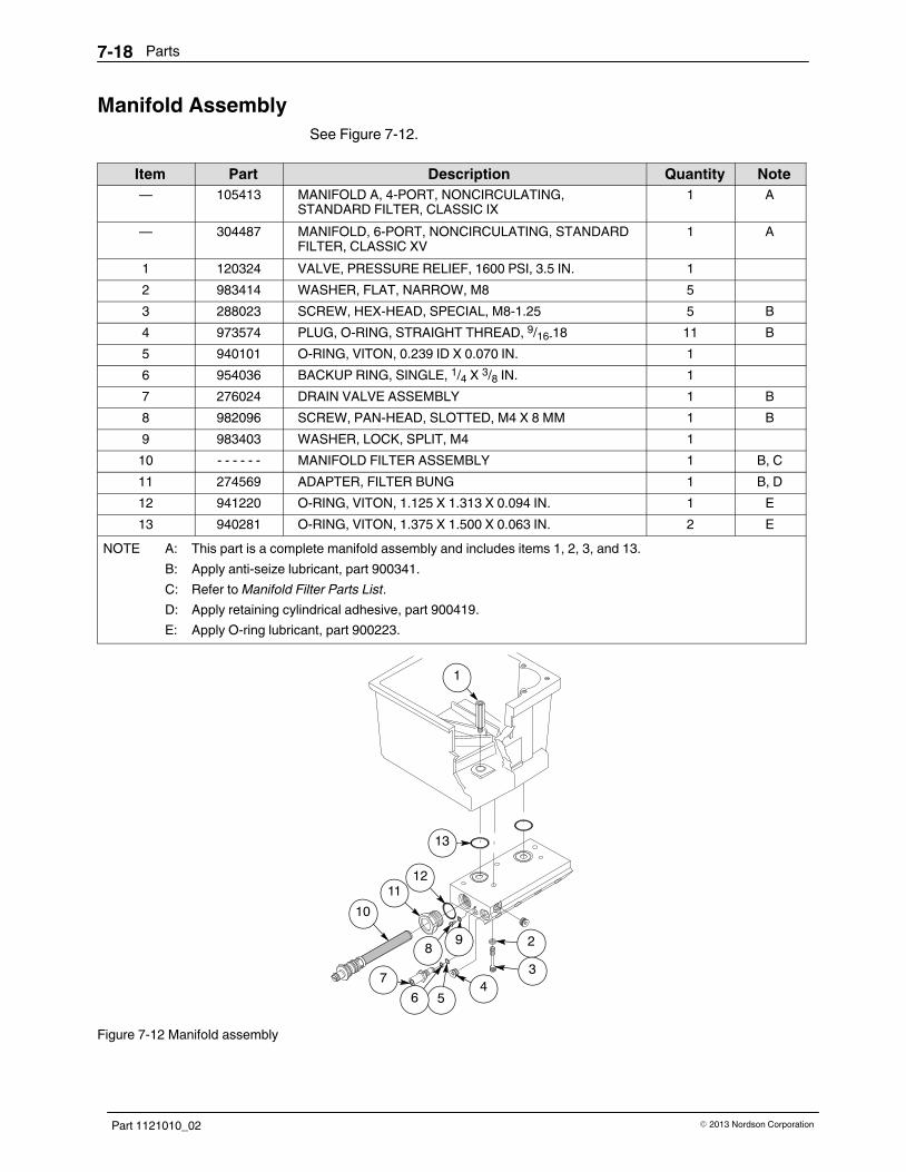
Parts7-18
Part 1121010_02 � 2013 Nordson Corporation
Manifold Assembly
See Figure 7‐12.
Item Part Description Quantity Note
— 105413 MANIFOLD A, 4‐PORT, NONCIRCULATING,STANDARD FILTER, CLASSIC IX
1 A
— 304487 MANIFOLD, 6‐PORT, NONCIRCULATING, STANDARDFILTER, CLASSIC XV
1 A
1 120324 VALVE, PRESSURE RELIEF, 1600 PSI, 3.5 IN. 1
2 983414 WASHER, FLAT, NARROW, M8 5
3 288023 SCREW, HEX‐HEAD, SPECIAL, M8‐1.25 5 B
4 973574 PLUG, O‐RING, STRAIGHT THREAD, 9/16‐18 11 B
5 940101 O‐RING, VITON, 0.239 ID X 0.070 IN. 1
6 954036 BACKUP RING, SINGLE, 1/4 X 3/8 IN. 1
7 276024 DRAIN VALVE ASSEMBLY 1 B
8 982096 SCREW, PAN‐HEAD, SLOTTED, M4 X 8 MM 1 B
9 983403 WASHER, LOCK, SPLIT, M4 1
10 ‐ ‐ ‐ ‐ ‐ ‐ MANIFOLD FILTER ASSEMBLY 1 B, C
11 274569 ADAPTER, FILTER BUNG 1 B, D
12 941220 O‐RING, VITON, 1.125 X 1.313 X 0.094 IN. 1 E
13 940281 O‐RING, VITON, 1.375 X 1.500 X 0.063 IN. 2 E
NOTE A: This part is a complete manifold assembly and includes items 1, 2, 3, and 13.
B: Apply anti‐seize lubricant, part 900341.
C: Refer to Manifold Filter Parts List.
D: Apply retaining cylindrical adhesive, part 900419.
E: Apply O‐ring lubricant, part 900223.
2
11
1
3
8
13
12
10
9
564
7
Figure 7‐12 Manifold assembly

Parts 7-19
Part 1121010_02� 2013 Nordson Corporation
Manifold Filter
See Figure 7‐13.
Item Part Description Quantity Note
— 105432 MANIFOLD FILTER ASSEMBLY 1
1 274578 � SCREEN, 0.006 MESH, 5.38 IN. LONG 1
2 981747 � SCREW, ROUND‐HEAD, 10‐32 X 6.250 IN. 1 A
3 274513 � BUNG 1
4 941172 � O‐RING, VITON, 0.813 X 1.000 X 0.094 IN. 1
5 274579 � CORE, 5.718 IN. LONG 1
NOTE A: Apply anti‐seize lubricant, part 900341.
ÌÌÌÌÌÌÌÌÌÌÌÌÌÌÌÌÌÌÌÌÌÌÌÌÌÌÌÌÌÌÌÌÌÌÌÌÌÌÌÌÌÌÌÌÌÌÌÌ
3
4
5
1
2
Figure 7‐13 Manifold filter assembly

Parts7-20
Part 1121010_02 � 2013 Nordson Corporation
10:1 Piston Pump
See Figure 7‐14.
Item Part Description Quantity Note
— 1078310 PUMP ASSEMBLY, CLASSIC XV, 10:1 — A
— 1108387 PUMP ASSEMBLY, CLASSIC IX, 10:1 — A
1 982147 � SCREW, HEX‐HEAD, CAP M6 X 120 MM 4 B
2 983409 � WASHER, LOCK, M, SPLIT, M6 5
3 101358 � CAP, AIR CYLINDER, SINGLE‐ACTING 1 G
4 102317 � BUMPER, PISTON STOP 1
5 940440 � O‐RING, VITON, 3.750 X 3.875 X 0.063 IN. 1 C
6 288118 � CYLINDER, AIR, HIGH‐VOLUME 1
7 984092 � NUT, HEX, M6, LOCK 1 B
8 102318 � STOP, PUMP, PISTON 1
9 288115 � WASHER, PISTON, CUP, HIGH‐VOLUME 1
10 288116 � CUP, PISTON, HIGH‐VOLUME 1
11 288117 � WASHER, PISTON, SEAL, HIGH‐VOLUME 1
12 973121 � ELBOW, MALE, PIPE, HYD, 1/8, BRASS 1
13 973130 � ELBOW, PIPE, HYD, 90,1/8, STL, ZN 1
14 973004 � NIPPLE, STEEL, SCHED 40,1/8, 3.00, ZINC PLTD 1
15 331881 � SOLENOID ASSY, 10:1 PUMP 1
16 986200 � RETAINING RING, EXTERNAL, 112, BASIC 1
17 983533 � WASHER, FLAT, E, SPRING‐GUIDE 1
18 102321 � SUPPORT, SPRING GUIDE 1
19 102319 � SPRING, COMPRESSION, 11.33 X 1.50 X 0.162 IN. 1
20 288119 � ADAPTER, AIR CYLINDER, HIGH VOLUME 1 D
21 102323 � RETAINER, SPRING 1
22 984545 � NUT, LOCK, BEARING, PN-08 1
23 983184 � WASHER, LOCK, E, BEARING, PN-08 1
24 102324 � SEAT, BALL CHECK, VALVE 1 G
25 900000 � BALL, 440 STAINLESS STEEL, 0.375 IN. 1
26 102325 � MOUNT, PUMP, MACHINED, 10:1 1
27 986603 � RETAINING RING, INTERNAL, 81, BASIC 1
28 273138 � WASHER, 0.799 OD X 0.543 ID X 0.340 IN. THICK 1
29 273139 � SEAL, PUMP 1
Continued on next page

Parts 7-21
Part 1121010_02� 2013 Nordson Corporation
16
1
2
2
8
9
10
11
13
1415
1217
18
19
20
26
27
28
29
30
31
32
33
34
35
36
37
38
39
40
41
42
43
21
22
23
24
25
44
45
3
5
6
7
46
4
44
See Note H
Figure 7‐14 10:1 piston pump assembly

Parts7-22
Part 1121010_02 � 2013 Nordson Corporation
10:1 Piston Pump (contd)
See Figure 7‐14.
Item Part Description Quantity Note
30 344028 BODY, PUMP, SINGLE‐ACTING 1
31 1076997 CROSSOVER EXT, CLASSIC XV 1 B, H
32 954013 BACK‐UP RING, SINGLE, 7/16 X 9/16 IN. 1 H
33 940133 O‐RING, VITON, 0.426 ID X 0.700 IN. WIDTH 1 C, H
34 985309 PIN, GROOVE, TYPE‐A, 0.125 ID X 1.0 IN. 1
35 102322 ROD, PUMP, SINGLE‐ACTING 1
36 940121 O‐RING, VITON, 0.364 ID X 0.700 IN. 1 C
37 134166 PLUG, PISTON, SINGLE‐ACTING 1
38 940157 O‐RING, VITON, 0.562 ID X 0.688 IN. 1 C
39 102327 PISTON, PUMP, SINGLE‐ACTING, HYDRAULIC 1
40 102329 SCREW, SHOULDER, 1/4-20 X 0.312 IN. OD 1
41 240533 CAGE, BALL, SIPHON 1
42 900023 BALL, 440, STAINLESS STEEL, 0.750 IN. 1
43 240534 SEAT, SIPHON BALL 1
44 1076999 EXTENSION, PICK UP 1 H
45 1078313 O‐RING, HOTPNT, 0.875 X 1.125 X 0.125 1 C, H
46 333616 BRACKET, COVER, PUMP, 10:1 1
NOTE A: For a complete pump, order this part number.
B: Apply anti‐seize compound, part 900344.
C: Apply high‐temperature lubricant, part 900223.
D: Part of item 26 on pump assemblies 1002706 and 342804.
E: Assembly 102315 only.
F: Assemblies 1002706 and 342804 only.
G: Apply retaining cylindrical adhesive, part 900419.
H: The parts shown in the insert in Figure 7‐14 are specific to CM15 melters with 10:1 piston pump.

Parts 7-23
Part 1121010_02� 2013 Nordson Corporation
Air Pressure Regulator
See Figure 7‐15.
Item Part Description Quantity Note
— 165871 REGULATOR/FILTER ASSEMBLY, 90 PSI (4 HOSEAPPLICATORS)
—
— 165872 REGULATOR/FILTER ASSEMBLY, 90 PSI (6 HOSEAPPLICATORS)
—
1 165735 � REGULATOR, FILTER, AIR, 1/4 NPT 1
2 973490 � NIPPLE, BRASS, 40, 1/4 IN., 2.50 IN. (4 HOSEAPPLICATORS)
1
2 973491 � NIPPLE, BRASS, 40, 1/4 IN., 5.00 IN. (6 HOSEAPPLICATORS)
1
3 901258 � GAUGE, AIR, 1/8 NPT, 90 PSI 1
4 165870 SERVICE KIT, FILTER ELEMENT 1
5 165878 SERVICE KIT, FILTER BOWL 1
1
2
3
4
5
Figure 7‐15 Air pressure regulator assembly

Parts7-24
Part 1121010_02 � 2013 Nordson Corporation
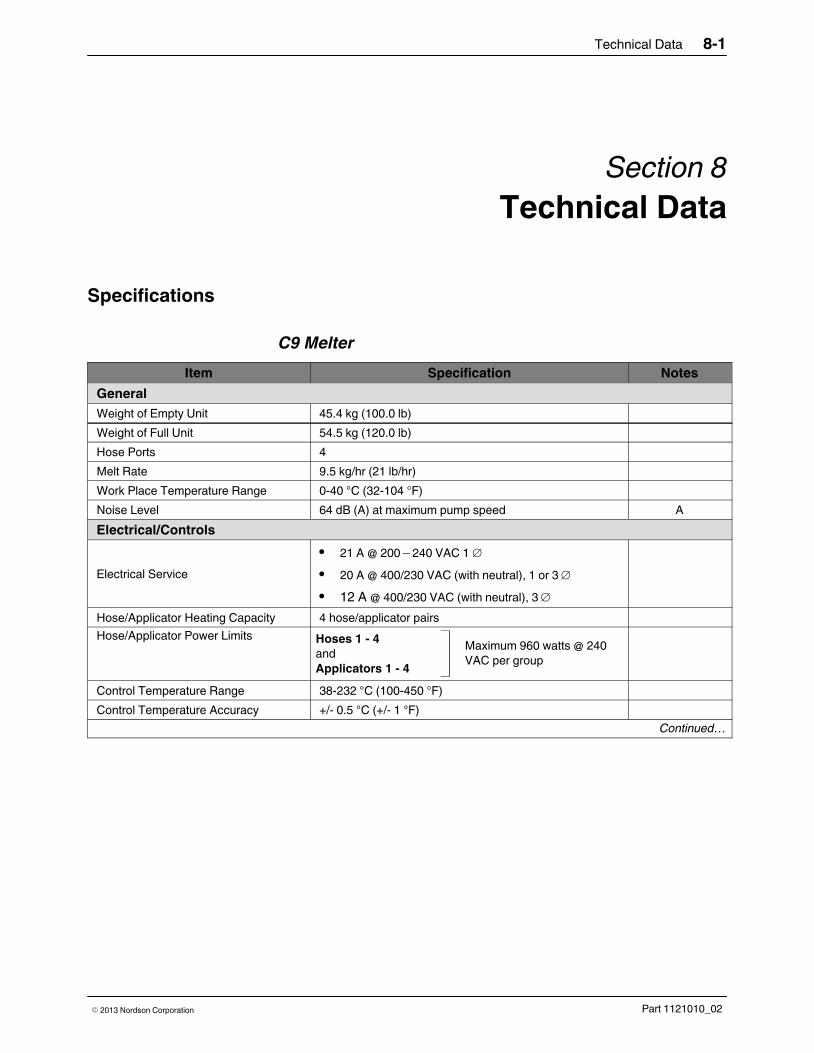
Technical Data 8-1
Part 1121010_02� 2013 Nordson Corporation
Section 8
Technical Data
Specifications
C9 Melter
Item Specification Notes
General
Weight of Empty Unit 45.4 kg (100.0 lb)
Weight of Full Unit 54.5 kg (120.0 lb)
Hose Ports 4
Melt Rate 9.5 kg/hr (21 lb/hr)
Work Place Temperature Range 0-40 C (32-104 F)
Noise Level 64 dB (A) at maximum pump speed A
Electrical/Controls
Electrical Service
� 21 A @ 200�240 VAC 1
� 20 A @ 400/230 VAC (with neutral), 1 or 3
� 12 A @ 400/230 VAC (with neutral), 3
Hose/Applicator Heating Capacity 4 hose/applicator pairs
Hose/Applicator Power LimitsMaximum 960 watts @ 240
VAC per group
Hoses 1 4
and
Applicators 1 - 4
Control Temperature Range 38-232 C (100-450 F)
Control Temperature Accuracy +/- 0.5 C (+/- 1 F)
Continued…

Technical Data8-2
Part 1121010_02 � 2013 Nordson Corporation
C9 Melter (contd)
Item Specification Notes
Pump
Type 10:1 single‐acting piston pump
Air Pressure while Running 0.7�4.8 bar (70�620 kPa, 10�90 psi)
Viscosity 800-30,000 mPas (up to 30,000 cps)
Hydraulic Pressure (maximum whilerunning)
10:1 pump: 6,200 kPa (900 psi)
Air Consumption at415 kPa (60�psi) and Maximum PumpSpeed
10:1 pump: 41 l/min (1.5 standard ft3/min)
Displacement 10:1 pump: 35 ml/stroke (2.14 in.3/stroke)
Output Rate (maximum) 10:1 pump: 0.67 kg/min (1.50 lb/min) B
Speed (maximum) 10:1 pump: 13 strokes/min
Tank
Capacity 8.6 kg (19 lb)
Volume 8.9 liters (540 in.3)
NOTE A: The noise level is measured at a distance of 1 m from the surface of the unit and at a height of 1.6 m fromthe access platform.
B: The output rate is based on a material density of 0.84 g/ml (0.03 lb/in.3) and a specific gravity of 0.84.
C15 Melter
Item Specification Notes
General
Weight of Empty Unit 60 kg (132 lb)
Weight of Full Unit 73.6 kg (162 lb)
Hose Ports 6
Melt Rate 13.6 kg/hr (30 lb/hr)
Work Place Temperature Range 0-40 C (32-104 F)
Noise Level 64 dB (A) at maximum pump speed A
Electrical/Controls
Electrical Service
� 27 A @ 200�240 VAC 1
� 26 A @ 400/230 VAC (with neutral), 1 or 3
� 17 A @ 400/230 VAC (with neutral), 3
Hose/Applicator Heating Capacity 6 hose/applicator pairs B
Hose/Applicator Power LimitsMaximum 960 watts @ 240
VAC total, 1 or 3 Hoses 1-3
Hoses 4-6
Applicators 1 - 3
Applicators 4-6Maximum 2400 watts @ 240
VAC total, 1
Control Temperature Range 38-232 C (100-450 F)
Control Temperature Accuracy +/- 0.5 C (+/- 1 F)
Continued…

Technical Data 8-3
Part 1121010_02� 2013 Nordson Corporation
Item Specification Notes
PumpAir Pressure while Running 10:1 pump: 0.7-4.8 bar (70-620 kPa, 10-90 psi)
Viscosity 800‐30,000 mPas (up to 30,000 cps)
Hydraulic Pressure (maximum whilerunning)
10:1 pump: 6,200 kPa (900 psi)
Air Consumption at 415 kPa (60 psi) and Maximum PumpSpeed
10:1 pump: 41 l/min (1.5 standard ft3/min)
Displacement 10:1 pump: 35 ml/stroke (2.14 in.3/stroke)
Output Rate (maximum) 10:1 pump: 0.67 kg/min (1.50 lb/min) C
Speed (maximum) 10:1 pump: 13 strokes/min
Tank
Capacity 13.6 kg (30 lb)
Volume 13.7 liters (836 in.3)
NOTE A: The noise level is measured at a distance of 1 m from the surface of the unit and at a height of 1.6 m fromthe access platform.
B: To determine the number of hose and applicator pairs that your unit can heat, refer to Melter Assembly PartNumbers in Section 8, Parts.
C: The output rate is based on a material density of 0.84 g/ml (0.03 lb/in.3) and a specific gravity of 0.84.
Electrical Specifications
Item Specification
Hose/applicator heating capacity2 (C9) hose/applicator pair or 4 (C15) hose/applicatorpair
Control temperature range (240 and 120 VAC) 93 to 204 C (200 to 400 F)
Control temperature accuracy � 0.5 C (� 1 F)
IP rating IP 32 - court
Heater Specifications
NOTE: Refer to the hose and applicator manuals for hose/applicator heaterspecifications.
Location VoltageWattage
(see Note A)Cold Resistance
(see Note B)
Tank, C9 230 V 2800 17-20 ohms
Tank, C15 230 V 3800 12-15 ohms
NOTE A: Nominal wattage at 177-204 �C (350-400 �F).
B: Measured at room temperature for a previously heated element.

Technical Data8-4
Part 1121010_02 � 2013 Nordson Corporation
Wiring Diagrams ‐ C9 Melter, 400Y
Figure 8‐1 C9 melter wiring diagram, 1

Technical Data 8-5
Part 1121010_02� 2013 Nordson Corporation
Figure 8‐2 C9 melter wiring diagram, 2

Technical Data8-6
Part 1121010_02 � 2013 Nordson Corporation
Wiring Diagrams ‐ C15 Melter, 400Y
Figure 8‐3 C15 melter wiring diagram, 1

Technical Data 8-7
Part 1121010_02� 2013 Nordson Corporation
Figure 8‐4 C15 melter wiring diagram, 2

Technical Data8-8
Part 1121010_02 � 2013 Nordson Corporation
C9 Melter Schematics, 400Y
Figure 8‐5 C9 melter schematics
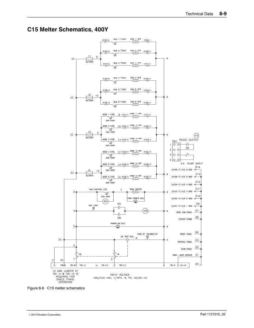
Technical Data 8-9
Part 1121010_02� 2013 Nordson Corporation
C15 Melter Schematics, 400Y
Figure 8‐6 C15 melter schematics

Technical Data8-10
Part 1121010_02 � 2013 Nordson Corporation

EC Declaration of Conformity
for Adhesive and Sealant Application Equipmentconforming to European Council Directives
PRODUCTS:
C9 Melters
C15 Melters
APPLICABLE DIRECTIVES:
Machinery Directive: 2006/42/EC
STANDARDS USED TO VERIFY COMPLIANCE:
EN ISO 12100 EN 60204-1
EN ISO 13732-1
PRINCIPLES:
This product has been manufactured according to good engineering practice.
The product specified conforms to the directives and standards described above.
Technical File Contact:
Dieter Ziesmer
Nordson Engineering GmbH
Lilienthalstrasse 6
21337 Lueneburg
GERMANYDate: 2/January/2013
Peter Lambert, Senior Vice PresidentAdhesives Dispensing Systems
1121566_01
DOC077R1
Nordson Corporation � 28601 Clemens Road �Westlake, Ohio
Model Number_________________________
Serial Number______________________________________


 2 (M = Rh, Ir; dimen = 1 ... · c14 c12 c15 109(2) c9 c13 c20 141(2) c14 c12 c19 109(2) c9 c13 c21 51(2) c15 c12 c19 109(2) c17 c13 c20 109(2) n1a](https://img.pdfslide.net/doc/110x75/5ffcbf1579204123507a96dd/structures-of-m-2-dimen-4-y-2-m-rh-ir-dimen-1-c14-c12-c15-1092.jpg)