Embed Size (px)
Citation preview

Crystallization in High Level Waste (HLW) Glass Melters: Operational Experience from the Savannah River Site
K. M. Fox February 2014 SRNL-STI-2013-00724, Revision 0

SRNL-STI-2013-00724 Revision 0
ii
DISCLAIMER
This work was prepared under an agreement with and funded by the U.S. Government. Neither the U.S. Government or its employees, nor any of its contractors, subcontractors or their employees, makes any express or implied:
1. warranty or assumes any legal liability for the accuracy, completeness, or for the use or results of such use of any information, product, or process disclosed; or
2. representation that such use or results of such use would not infringe privately owned rights; or
3. endorsement or recommendation of any specifically identified commercial product, process, or service.
Any views and opinions of authors expressed in this work do not necessarily state or reflect those of the United States Government, or its contractors, or subcontractors.
Printed in the United States of America
Prepared for
U.S. Department of Energy

SRNL-STI-2013-00724 Revision 0
iii
Keywords: HLW, Glass, Melter, Crystallization Retention: Permanent
Crystallization in High Level Waste (HLW) Glass Melters: Operational Experience from the Savannah River Site
K. M. Fox
February 2014
Prepared for the U.S. Department of Energy under contract number DE-AC09-08SR22470.

SRNL-STI-2013-00724Revision 0
iv
REVIEWS AND APPROVALS
AUTHORS:
______________________________________________________________________________K. M. Fox, Engineering Process Development Date
TECHNICAL REVIEW:
______________________________________________________________________________D. K. Peeler, Process Technology Programs, Reviewed per E7 2.60 Date
APPROVAL:
______________________________________________________________________________D. H. McGuire, Manager DateProcess Technology Programs
______________________________________________________________________________C. C. Herman, Manager DateHanford Strategic Initiatives
______________________________________________________________________________S. L. Marra, Manager DateEnvironmental & Chemical Process Technology Research Programs

SRNL-STI-2013-00724 Revision 0
v
EXECUTIVE SUMMARY
A road map was recently developed to guide research and development efforts for a crystal tolerant glass processing strategy for the Hanford Tank Waste Treatment and Immobilization Plant (WTP). The basis of this alternative approach is an empirical model predicting the crystal accumulation in the WTP glass discharge riser and melter bottom as a function of glass composition, time, and temperature. When coupled with an associated operating limit (e.g., the maximum tolerable thickness of an accumulated layer of crystals), this model could then be integrated into the process control algorithms to formulate crystal tolerant high level waste (HLW) glasses targeting higher waste loadings while still meeting process related limits and melter lifetime expectancies. This report provides a review of the scaled melter testing that was completed in support of the Defense Waste Processing Facility (DWPF) melter. Testing with scaled melters provided the data to define the DWPF operating limits to avoid bulk (volume) crystallization in the un-agitated DWPF melter and provided the data to distinguish between spinels generated by K-3 refractory corrosion versus spinels that precipitated from the HLW glass melt pool. This report includes a review of the crystallization observed with the scaled melters and the full scale DWPF melters (DWPF Melter 1 and DWPF Melter 2). Examples of actual DWPF melter attainment with Melter 2 are given. The intent is to provide an overview of lessons learned, including some example data, that can be used to advance the development and implementation of an empirical model and operating limit for crystal accumulation for WTP. Operation of the first and second (current) DWPF melters has demonstrated that the strategy of using a liquidus temperature predictive model combined with a 100 °C offset from the normal melter operating temperature of 1150 °C (i.e., the predicted liquidus temperature (TL) of the glass must be 1050 °C or less) has been successful in preventing any detrimental accumulation of spinel in the DWPF melt pool, and spinel has not been observed in any of the pour stream glass samples. Spinel was observed at the bottom of DWPF Melter 1 as a result of K-3 refractory corrosion. Issues have occurred with accumulation of spinel in the pour spout during periods of operation at higher waste loadings. Given that both DWPF melters were or have been in operation for greater than 8 years, the service life of the melters has far exceeded design expectations. It is possible that the DWPF liquidus temperature approach is conservative, in that it may be possible to successfully operate the melter with a small degree of allowable crystallization in the glass. This could be a viable approach to increasing waste loading in the glass assuming that the crystals are suspended in the melt and swept out through the riser and pour spout. Additional study is needed, and development work for WTP might be leveraged to support a different operating limit for the DWPF. Several recommendations are made regarding considerations that need to be included as part of the WTP crystal tolerant strategy based on the DWPF development work and operational data reviewed here. These include:
• Identify and consider the impacts of potential heat sinks in the WTP melter and glass pouring system
• Consider the contributions of refractory corrosion products, which may serve to nucleate additional crystals leading to further accumulation
• Consider volatilization of components from the melt (e.g., boron, alkali, halides, etc.) and determine their impacts on glass crystallization behavior
• Evaluate the impacts of glass REDuction/OXidation (REDOX) conditions and the distribution of temperature within the WTP melt pool and melter pour chamber on crystal accumulation rate
• Consider the impact of precipitated crystals on glass viscosity • Consider the impact of an accumulated crystalline layer on thermal convection currents and
bubbler effectiveness within the melt pool

SRNL-STI-2013-00724 Revision 0
vi
• Evaluate the impact of spinel accumulation on Joule heating of the WTP melt pool • Include noble metals in glass melt experiments because of their potential to act as nucleation sites
for spinel crystallization

SRNL-STI-2013-00724 Revision 0
vii
TABLE OF CONTENTS LIST OF TABLES ..................................................................................................................................... viii
LIST OF FIGURES ................................................................................................................................... viii
LIST OF ABBREVIATIONS ...................................................................................................................... ix
1.0 Introduction ............................................................................................................................................. 1
1.1 Quality Assurance ............................................................................................................................... 2
2.0 Literature Review .................................................................................................................................... 2
2.1 Scale Melter Testing in Support of DWPF Design ............................................................................. 2
2.1.1 Project S-1941 Melter ................................................................................................................... 3
2.1.2 Small Cylindrical Melter (SCM) .................................................................................................. 4
2.1.3 Large Slurry Fed Melter (LSFM) ................................................................................................. 5
2.1.4 Scale Glass Melter (SGM) ............................................................................................................ 5
2.1.5 Integrated DWPF Melter System (IDMS) .................................................................................... 6
2.2 DWPF Melter 1 Inspection after 1.75 Years of Non-Radioactive Startup Campaigns ....................... 7
2.3 DWPF Melter 1 Inspection after Radioactive Operation .................................................................... 9
2.4 DWPF Melter 2 Crystallization Issues and Analyses ........................................................................ 10
2.5 DWPF Melter Pour Stream Sample Analyses ................................................................................... 10
2.6 Suspension of Spinels in the DWPF Melter ...................................................................................... 11
3.0 DWPF Melter 2 Operating Data ........................................................................................................... 11
4.0 Summary ............................................................................................................................................... 16
5.0 References ............................................................................................................................................. 18
Appendix A . DWPF Melter Temperature Data for Selected Times during August 2003 ...................... A-1

SRNL-STI-2013-00724 Revision 0
viii
LIST OF TABLES Table 2-1. Summary of Crystallization Data from DWPF Pour Stream Sample Analyses. ...................... 11
Table 3-1. Fiscal Year 2011 DWPF Melter Downtime Key Event Timeline. ........................................... 13
Table 3-2. Fiscal Year 2012 DWPF Melter Downtime Key Event Timeline. ........................................... 15
LIST OF FIGURES Figure 2-1. Cross-sectional Overview of the DWPF Melter. ....................................................................... 8

SRNL-STI-2013-00724 Revision 0
ix
LIST OF ABBREVIATIONS
CPC Chemical Processing Cell CSEM Contained Scanning Electron Microscopy DOE Department of Energy DWPF Defense Waste Processing Facility EDS Energy Dispersive Spectroscopy HLW High Level Waste IDMS Integrated DWPF Melter System LAW Low Activity Waste LSFM Large Slurry Fed Melter MFT Melter Feed Tank ORP Office of River Protection PNL Pacific Northwest Laboratory POG Primary Off-Gas REDOX REDuction/OXidation SCM Small Cylindrical Melter SGM Scale Glass Melter SME Slurry Mix Evaporator SRAT Sludge Receipt and Adjustment Tank SRNL Savannah River National Laboratory SRS Savannah River Site T1% Temperature at which glass contains 1 vol % crystallization TDS Technical Data Summary TL Liquidus Temperature TTT Time-Temperature-Transformation WTP Tank Waste Treatment and Immobilization Plant WVDP West Valley Demonstration Project XRD X-ray Diffraction

SRNL-STI-2013-00724 Revision 0
1
1.0 Introduction The U.S. Department of Energy (DOE) is building a Tank Waste Treatment and Immobilization Plant (WTP) at the Hanford Site in Washington to remediate 55 million gallons of radioactive waste that is being temporarily stored in 177 underground tanks. The plan is to separate the radioactive waste into high-level waste (HLW) and low-activity waste (LAW) fractions that will then be vitrified in stable borosilicate glass with Joule-heated ceramic melters. Efforts are being made to increase the loading of Hanford tank wastes in glass while maintaining an adequate ability to meet process, regulatory, and product quality requirements.
Recent glass formulation and melter testing data have suggested that significant increases in waste loading in HLW and LAW glasses are possible over current system planning estimates.1 The existing WTP data (although limited in some cases) were evaluated to determine a set of constraints and models that could be used to estimate the maximum loading of specific waste compositions in glass. It was recognized that some of the models are preliminary in nature and some do not currently address prediction uncertainties that would be needed before they could be used in plant operations. However, the assessments based on these enhanced models or advanced glass formulations show significant improvement in waste loading, and thus, continuing to assess their potential applicability is of utmost importance.
Belsher and Meinert identified five constraints that were most influential on the estimated Hanford HLW glass volumes.2 One of those constraints was the limit of no more than one volume percent spinel crystals in the melt (T1%) at a temperature of 950 °C. That is, the glass must contain 1 vol% spinel crystals or less at 950 °C when subjected to ASTM C1720, Standard Test Method for Determining Liquidus Temperature of Immobilized Waste Glasses and Simulated Waste Glasses, in order to be considered acceptable. Historically, crystallization constraints are placed in process control systems to prevent premature or catastrophic failure of the melter through bulk devitrification (also known as volume crystallization) or crystal accumulation and, thus, to mitigate negative impacts of crystals as glass is produced.a Joule-heated melter technology was successfully used from 1996 to 2002 at the West Valley Demonstration Project (WVDP) in New York, and has been in continuous use at the Defense Waste Processing Facility (DWPF) at the Savannah River Site (SRS) since radioactive operations began there in April 1996. The baseline method of controlling crystallization in the WTP HLW melter uses a model that predicts the temperature, T1%, at which the equilibrium fraction of spinel crystals in the melt is 1 vol% (nominally at 950 °C).4 In contrast, the DWPF melter is operated with a model that predicts the liquidus temperature (TL) of the glass as a function of its composition.3,5,6 The predicted TL value for DWPF must be at least 100 °C below the nominal melter operating temperature (1150 °C) in order for the feed to be acceptable for transfer to the melter.7 This approach sets the liquidus temperature at the point where no spinel crystals are detected. The TL operating limit is used in DWPF to minimize the risk of bulk devitrification in the melt pool. This approach has been used at DWPF since non-radioactive start-up in April 1994 and has been successful at eliminating bulk devitrification within the melt pool leading to catastrophic melter failure or significant processing issues associated with crystallization in or from the melt pool. In fact, the first DWPF melter operated for 8 years, far exceeding the two-year life expectancy that is based on refractory corrosion.8 The second melter has continually supported facility operations since March 2003, thus further exceeding the design life. a Jantzen and Brown provide a brief review of the potential, negative effects of crystallization within a melter.3
SRNL-STI-2013-00724 Revision 0
2
It is possible that the DWPF liquidus temperature approach is conservative, in that it may be possible to successfully operate the melter with a small degree of allowable crystallization in the glass. An alternative crystal-tolerant glass approach9 may allow higher waste loading for WTP processing while maintaining a chemically durable glass product. Some crystalline phases, such as spinel, do not impact the durability of the waste form10 but may accumulate in the melter or riser and restrict or prevent its operation. However, prediction of spinel precipitation and accumulation could potentially allow for formulating higher waste loading, durable glasses if an alternative strategy for operating and idling a melter with some amount of tolerable crystals can be developed and implemented. Given the identification of the T1% constraint as one of the most influential constraints for estimated Hanford HLW glass volumes, the DOE-Office of River Protection (ORP) has initiated a program to evaluate whether this constraint can be relaxed or whether new constraints could be developed to replace the current T1% approach.11,12 A study of the design and operation of the WTP HLW melter suggests that spinel accumulation in the 76 mm diameter glass discharge riser is the most limiting design aspect of the melter, and can most likely prevent discharge of the molten glass into canisters, especially when considering frequent and periodic idling.a A road mapb was recently developed to guide research and development efforts for a crystal tolerant glass processing strategy for WTP. The basis of this potential, alternative approach will be an empirical model predicting the crystal accumulation in the WTP glass discharge riser and melter bottom as a function of glass composition, time, and temperature.9 When coupled with an associated operating limit, this model could then be integrated into the process control algorithms to formulate crystal tolerant HLW glasses targeting higher waste loadings while still meeting other process related limits and melter lifetime expectancies. This report provides a review of the scaled melter testing that was completed in support of DWPF development, a review of crystallization observed with the full scale DWPF melters, and examples of actual DWPF melter attainment with Melter 2. The intent is to provide an overview of lessons learned, including some example data, that can be used to advance the development and implementation of an empirical model13 and operating limit for crystal accumulation for WTP.
1.1 Quality Assurance This review is performed as part of a Task Technical and Quality Assurance Plan.14 Requirements for performing reviews of technical reports and the extent of review are established in manual E7 2.60. The Savannah River National Laboratory (SRNL) documents the extent and type of review using the SRNL Technical Report Design Checklist contained in WSRC-IM-2002-00011, Rev. 2.
2.0 Literature Review
2.1 Scale Melter Testing in Support of DWPF Design Jantzen, et al. provide a description of scale melter testing in support of the design of the DWPF, with a focus on the buildup of crystals in various areas of the melters.15 This information will be summarized here in the context of crystal accumulation data to support the development of the crystal-tolerant glass approach for the WTP melter. An extensive review of scale melter testing is
a Vienna, J. D., personal communication, February 21, 2014. b Matyáš, J., J. D. Vienna, D. K. Peeler, K. M. Fox, and C. C. Herman, “Road Map for Development of Crystal-Tolerant High Level Waste Glasses,” SRNL-STI-2013-00734, in draft.

SRNL-STI-2013-00724 Revision 0
3
included as part of the DWPF Glass Melter Technology Manual,16 portions of which will also be summarized here.
2.1.1 Project S-1941 Melter The Project S-1941 scale melter was the first prototype designed for DWPF development work.16 It was a cylindrical melter with electrodes for Joule heating of the melt pool entering from the top of the melter. The melter was originally operated with a calcined feed, and was later slurry fed. The riser was heated with an Inconel® 690 resistance heater. Glass in the riser contacted the heater directly. The riser was refractory lined and 6 inches in diameter. The riser heater, which was centered along the long axis of the riser, was 3 inches in diameter. This created an annular flow channel for the glass in the riser. The pour spout was approximately 1.875 inches in diameter. The pour spout was heated by an element surrounding the pour stream disengagement point. A total of 74 tons of glass were produced with the 1941 melter, including 20 tons produced via slurry feeding.16 The 1941 melter was dismantled to evaluate the effects of glass production on the melter materials and deposition of residual products.17 A slag layer approximately 7 inches deep had accumulated at the bottom of the melter. Material up to 1 inch thick had accumulated on the melter walls, and the riser and pour spout were nearly plugged with glass containing a high concentration of spinel particles. The slag at the bottom of the melter was shown to consist of three layers, consisting mainly of Fe-Ni-Mn and Fe-Ni-Mn-Cr spinel phases in a glass matrix. A sodium calcium iron silicate phase was present in the upper two layers. The material adhered to the melter walls consisted of a reaction zone between the Monofrax K-3 refractory and the glass, and a glass layer containing more than 30 vol % FeNiMn spinel particles. The lack of Cr in the spinel phase that was found in the glass adhered to the walls indicated that the crystallization in this glass layer was not a result of refractory corrosion. The higher viscosity of the glass due to the presence of the spinel crystals was concluded to be the cause of the glass remaining on the walls of the melter.17 The accumulation of crystals in the 1941 melter was correlated to the thermal history over the period of operation.17 The melter was operated above 1200 °C for the first three months, including seven days at about 1300 °C. This resulted in accelerated refractory corrosion, and likely led to the accumulation of Cr-containing spinels and higher concentrations of Al in the glass at the bottom of the melter. This accumulation generated the first of the three layers identified in the later inspection. The upper two layers were determined to have formed due to low temperature operation. The liquidus temperature of the Frit 131 and Technical Data Summary (TDS) waste melter feed was 1081 °C.a The 1941 melter experienced two periods of low temperature idling, one for 58 days at 1050 °C, and another for about one month where the melter was shut down (thermally cycled) one to three times per day. The slag layer was probed and found to be 7 inches thick after the 58 day idling period. Additional slag accumulation was not observed after the one month period of thermal cycling. It was hypothesized that the conditions during cycling did not favor the kinetics of spinel crystallization.17 The accumulation of spinel in the bottom of the 1941 melter eventually led to spinel coming out of the melter with the glass to the point where the glass quality (qualitative) was considered to be affected.17 Increased riser temperature and rocking of the melter were needed in order to continue pouring near the end of the melter campaign. Heat loss through the melter bottom refractory contributed in part to the issues with spinel formation. The DWPF melter bottom refractory was a Jantzen, et al. provide a thorough compilation of available glass composition data for the various SRS pilot scale melter campaigns, along with predicted liquidus temperatures and viscosity values.15

SRNL-STI-2013-00724 Revision 0
4
later designed to ensure that the glass would freeze in the refractory while maintaining a hot face temperature of 1050 °C.16 The vertical electrode configuration of the 1941 melter (and the Small Cylindrical Melter, described in Section 2.1.2) likely also contributed to the accumulation of spinels at the bottom of the melter.18 Spinel (and potentially, reduced metals) accumulation at the bottom of the melter may have reduced the resistance of the glass at the bottom of the melter, leading to power skewing to the bottom and cooling of the upper melt pool to below the liquidus temperature, causing additional spinel formation. The higher viscosity of glass with spinel crystals reduces the ability to transfer its heat to the rest of the melt pool via convective transport. The vertical electrode configuration does not allow for the power profile to be intentionally skewed to the top of the melt pool to prevent this situation.18 The DWPF melter uses upper and lower pairs of diametrically opposed electrodes to provide better melt pool temperature control.16
2.1.2 Small Cylindrical Melter (SCM) The SCM was used for performance testing of DWPF melter materials of construction with a variety of glass compositions.19 It was a roughly octagonal melter with electrodes for Joule heating of the melt pool entering from the top of the melter. The riser was not heated, and was constructed with Monofrax K-3 refractory. An Inconel® 690 sleeve was inserted into the riser for the last of the three melter campaigns because of refractory corrosion. Supplementary heat was provided in the pour chamber by silicon carbide elements.20 The melter ran for 786 days, including idle periods. It produced 51,521 pounds of glass via powder feeding and 11,359 pounds of glass via slurry feeding.19 The SCM melter accumulated approximately 0.5 inches of a crystalline slag layer at the bottom after approximately 4.5 months (the first campaign) of processing Frit 211 and simulated TDS waste with a liquidus temperature of approximately 1050 °C.20 The melter was operated (feeding, pouring, and idling) at temperatures of 1050-1185 °C. At one point, a loss of power incident allowed the melter to cool to approximately 300 °C. The total duration of this incident was about two days.20 Analysis of samples taken from the slag layer identified the major crystalline phase as NiFe2O4. It was concluded that circulation in the melt pool must have been sufficient to sweep spinel from the melter since the bottom temperature was generally near the liquidus.20 An additional 0.5 inches of slag accumulated during the second melter campaign.21 The last phase of the second campaign involved feeding a mixture of Pacific Northwest Laboratory (PNL) calcine with Frit 211 at a deliberately low19 melt pool temperature of 1040-1070 °C for about five days. This resulted in the accumulation of another 0.5 inches of slag on the bottom of the melter when the TL of the glass was approximately 1050 °C.21 During the third and final campaign with the SCM melter, Frit 131 and simulated waste slurry at a waste loading of approximately 50 wt % was inadvertently fed to the melter. This resulted in an area of high temperature forming at the bottom of the melter.19 Several steps were taken to try to alleviate the development of high temperatures at the bottom of the melter, including multiple attempts at feeding frit only to flush the melter, stirring the melt pool with a metal rod, air sparging, and tilting the melter to its maximum angle for draining. In all cases, these measures provided only temporary improvements in the melt pool temperature profile. That is, the melt pool bottom temperature would approach the maximum allowable (1170 °C), where power would then have to be reduced, resulting in the upper melt pool cooling to below the liquidus temperature and the formation of spinel.19 Samples taken from the bottom of the SCM after the third campaign consisted mainly of spinels, including trevorite, magnetite, hercynite, and a small amount of acmite. It was concluded that the high temperatures at the bottom of the melter were the result of increased viscosity of the spinel laden glass at the bottom of the melt pool rather than differences in conductivity, since reduced

SRNL-STI-2013-00724 Revision 0
5
metals were not found in the slag. The higher viscosity of the material at the bottom of the melter hindered heat transfer via convection.19 Also note that the Project S-1941 Melter and the SCM were fed with calcine material, which was shown to contribute to slag accumulation on the bottom of the melters.22 Slurry feeding was therefore used with the other scale melters and the DWPF melter.
2.1.3 Large Slurry Fed Melter (LSFM) The LSFM was designed and operated to evaluate slurry feeding with various glass compositions and off-gas system configurations.16 The melter was octagonal with a flat bottom. The walls and floor of the LSFM were more heavily insulated as compared to the 1941 melter since the LSFM vessel was not water cooled. There were two pairs of diametrically opposed electrodes with independent power supplies for Joule heating of the melt pool, similar to the final design of the DWPF melter. Supplementary heat was provided in the pour chamber by silicon carbide elements.23 A riser heater is depicted in engineering drawings of the LSFM.16,23 The melter produced 234 tons of glass over a period of 749 days. Of this time period, 556 days were spent idling at 1100-1150 °C.16 The riser temperatures were reported to be in the range of 1125 °C ± 10 °C and the pour spout temperatures were reported to be 1075 °C ± 10 °C during the fifth campaign.24 The LSFM was disassembled for inspection after being drained to determine the performance of the materials of construction. A thin layer of crystalline material was found at the bottom of the melter, ranging from 0.0625 to 0.5 inches thick and consisting of chromium-nickel-iron spinel. The accumulation of spinels was determined to be a result of corrosion of the Monofrax K-3 refractory.23
2.1.4 Scale Glass Melter (SGM) The Project S-1941 melter was later converted to the DWPF design under Project S-4234 in order to verify operation of several DWPF equipment designs.16 The SGM melt pool was scaled to 2/3 of the full scale DWPF melter and used prototypic refractories, including an insulating bottom layer designed to maintain a hot face temperature on the melter floor. There were two pairs of diametrically opposed electrodes with independent power supplies, scaled to 2/3 the size of those in the DWPF melter. The riser and pour spout were heated with Inconel® 690 electrical resistance heaters. The riser heater was designed to maintain the glass temperature at 1050-1170 °C.25 Changes to the thermocouple positioning in the riser were needed to correct a riser heater failure at startup due to overheating.16 Glass samples taken close to the bottom of the SGM after the fifth campaign contained no crystalline phases, although the actual depth from which the sample was retrieved was questioned.22 The lack of crystallization was attributed to better melter design, slurry feeding rather than feeding calcined material, control of rheology and REDuction/OXidation (REDOX) by formic acid addition, and more soluble frit compositions.22 The SGM was completely drained after the ninth campaign15 and the bottom of the melter was inspected with a remote video camera.26 Material that appeared to be crystalline was noted along the ledge where the melter side walls met the floor. No significant accumulation of crystalline material is noted in the report.26 Although no significant accumulation was reported on the melter floor, the SGM riser was plugged multiple times during the first campaign.27 Samples of the material that plugged the riser were characterized and found to consist largely of acmite. A comparison with time-temperature-transformation (TTT) curves developed for a similar glass chemistry indicated that times of more

SRNL-STI-2013-00724 Revision 0
6
than 24 hours at temperatures of 600-800 °C would have been necessary for the almost complete devitrification of the glass to acmite and, therefore, the riser was not being kept hot enough. The lack of spinel in the crystalline material from the riser, coupled with the TTT data, further demonstrated that the riser temperature had been below 750 °C.15,27 Devitrification in the SGM riser and pour spout was remediated via improvements to the insulation design.28
2.1.5 Integrated DWPF Melter System (IDMS) The IDMS was a 1/9 scale demonstration of the DWPF feed preparation, melter (1/9 scale), and off-gas systems.29 The melter shell was basically the same design as the SCM, with an additional 12 inches of Monofrax K-3 refractory used to reduce the melt pool diameter to 24 inches. There were two pairs of diametrically opposed electrodes with independent power supplies. The riser and pour spout were heated with serpentine Inconel® 690 heaters. The riser was heated to 1100 °C and the pour spout was heated to 1050 °C to maintain the flow of glass.29 Issues with pluggage of the pour spout were noted during the early, sludge-only runs (i.e., feed consisting of simulated sludge and glass frit without simulated streams from salt processing) of the IDMS.29 The pour spout became plugged with glassa at least seven times during the second sludge-only runs. The pluggages were attributed to a low rate of glass pouring. This was alleviated by modifying the vacuum pouring system to better control the glass flow rate. Additional pluggages were due to a wavering pour stream causing the glass to contact colder regions of the pour spout below the normal disengagement point. Wavering of the pour stream was attributed to the temperatures in the pour spout being too low. Similar behavior was later observed in the DWPF melter, resulting in the addition of a pour spout insert and a heated bellows liner.8 Pouring was improved by increasing the set point of the pour spout control thermocouple from 1020 °C to 1100 °C and by increasing the set point of the primary channel exit point thermocouple from 932 °C to 974 °C. 29 Glass samples were taken from close to the floor of the IDMS (3-5 cm above the refractory) once noble metals were included in the feed.30 The samples were taken through the melter feed port. The intent was to identify any accumulation of noble metals that could lead to problems with Joule heating. No noble metals deposits were found after two months of operation with noble metals in the feed. RuO2 deposits with a needle-like morphology were found in a floor sample collected after seven months of operation with noble metals in the feed. After approximately 13 months, a melter floor sample was collected and found to consist of a denser layer of RuO2 and (Ni,Mn)(Fe,Cr) spinels. Samples collected over the next two months continued to exhibit RuO2, Rh, and spinel accumulation. A sample collected after the completion of processing of Hanford Waste Vitrification Plant feed, HWVP2, had decreased concentrations of Ru, Rh, and spinel components. These data correlated with analyses of the glass produced during HWVP1 and HWVP2 production, where Cr concentrations were 60-230% higher in the glass product than in the melter feed. These results were attributed to flushing of spinels and noble metals from the melter during this period. A mechanism for this flushing was not identified, although convective currents in the melt pool were suggested as a potential cause.30 Additional melter floor samples were taken over time from both the feed port and the borescope port to determine whether the accumulated layer was uniform across the melter.30 The analysis of multiple samples suggested that the noble metal and spinel layer was not uniform, and that the material accumulated at the outside edges of the melter bottom. This was attributed to the action of convective currents in the melt pool.30 a Smith et al.29 refer to the pluggages as glass and do not mention any crystallization.

SRNL-STI-2013-00724 Revision 0
7
Further review of the noble metals data collected during the IDMS campaigns demonstrated the propensity for settling of noble metals and spinels during idle periods.31 Continuous melter feeding and pouring appears to generate sufficient convective currents to prevent the settling of melt insolubles, while idle periods allow settling to occur. It was recommended that DWPF avoid periods of idling when noble metals are present in the feed. A small number of extended idle periods were recommended as being preferable to multiple short idle periods to minimize the accumulation of noble metals and spinels.31 Following seven years of operation, the IDMS was shut down for examination to gather inspection data and minimize the need for future inspections of the DWPF melter and off-gas system.32 Samples were collected from the floor and drain of the IDMS in order to characterize any crystalline material. A vacuum pour was used to empty the melter since the bottom drain did not function, which left approximately 12 inches of glass remaining on the melter floor. Multiple samples were retrieved from across the melter floor, and their compositions were very consistent.32 The material was slightly enriched in Cr2O3 and contained noble metal oxides on the order of 0.04 wt % (equivalent to the concentration targeted in the glass). Spinels were present in concentrations of 3.2-8.5 wt %, as well as some amount of krinovite, which was attributed to decomposition of the K-3 refractory.33-35 Higher concentrations of spinels were found in samples that had been embedded in the K-3 refractory floor.32
2.2 DWPF Melter 1 Inspection after 1.75 Years of Non-Radioactive Startup Campaigns The full scale DWPF melter is cylindrical, with a melt pool diameter of about 1.83 m and Monofrax K-3 as the glass contact refractory.36 All metallic components within the melter are Inconel® 690. The first DWPF melter operated for more than eight years, producing approximately 2.4 x10⁶ kg of glass. The melter was operated at a glass temperature of 1050 °C to 1200 °C. Early operations were with an oxidizing melt pool (Fe2+/ΣFe=0.09 for Sludge Batch 1A and part of Sludge Batch 1B), and later operations (Sludge Batch 1B to shutdown) targeted a reduced melt pool (Fe2+/ΣFe=0.2). A cross section of the DWPF melter is depicted in Figure 2-1.

SRNL-STI-2013-00724 Revision 0
8
Figure 2-1. Cross-sectional Overview of the DWPF Melter.36 Note that this diagram shows
the melter configuration prior to the installation of bubblers.
In March and April 1996 (prior to radioactive operations), deposits formed in the DWPF melter pour spout on several occasions.34,35 There was concern that accumulated crystalline material on the floor of the DWPF melter could be a source of the pour spout deposits. Rodding of the melter showed two distinct layers of material on the melter floor. The bottom-most layer, which was about 1.5 inches in depth, was of high density, while the upper, “mushy” layer was less dense and was about 1 inch in depth.37 The total depth of the deposits accumulated over approximately 1.75

SRNL-STI-2013-00724 Revision 0
9
years of non-radioactive startup campaigns was about 2.5 inches. Glass samples and melter bottom deposit samples were obtained by inserting rods with sample cups welded to their bottoms through a nozzle in the melter top head until the bottom of the cups impacted the semi-solid “mushy” layer of deposits on the melter floor near the riser.37 The glass collected inside the two cups and the partially crystallized melter bottom deposits adhering to the bottom surfaces of the cups were characterized.34,35 Visually, a layer of crystalline deposits adhered to the bottom of the cups and partially up the outside of the sample cups. The cups were approximately 4 inches high and impacted the bottom deposits vertically such that no crystalline deposits were found inside the cups or further up the rods above the cups. The crystallized material adhering to the bottom of the sample cups was broken off and analyzed. The glass inside the cup, the glass on the upper surfaces of the cup, and the glass on the rod contained no visible crystalline material. The glass from inside the cup and glass adhering to the side of the rod were also analyzed. The results, provided in detail by Jantzen, et. al, indicated that the crystallized material adhering to the bottom of the sample cups was enriched in NiO, Fe2O3, and Cr2O3 as compared to the glass within the sample cups.34,35 X-ray diffraction analysis confirmed that the crystallized melter bottom deposits adhering to the bottom of the sampler cups were Ni-Fe-Cr spinels.34,35 The melter bottom deposits contained between 25-34 wt% spinel and some RuO2 as compared to the glass adhering to the side of the rod that contained only 0.7-5.2 wt % spinel. These DWPF melter bottom deposits were similar in composition to the melter bottom deposits analyzed from the IDMS in that they were enriched in NiO, Fe2O3, and Cr2O3.32 The accumulation of spinels in the DWPF melter has been attributed to refractory corrosion with an oxidizing melter feed, rather than crystallization within the melt, since the DWPF melter feed composition was controlled such that the predicted liquidus temperature was at least 100 °C below the melter temperature. Jantzen, et al. provide a method for, and examples of, calculating the accumulated depth of melter bottom deposits from refractory corrosion data.34,35 For example, DWPF Melter 1 had processed about 2.8 x 10⁵ pounds of glass after about 1.75 years of non-radioactive commissioning. The linear K-3 refractory corrosion equation given by Jantzen, et al. gives a loss of about 860 mils in 1.75 years. Assuming that the melter bottom deposits consist of an average of 35 wt % spinel and 65 wt % glass (from quantitative X-ray diffraction (XRD) analyses of the glass adhering to the cups), Jantzen, et al. calculate the approximate depth of the DWPF Melter 1 slag deposits to be about 2.3 inches after 1.75 years of operation with oxidizing feeds. The result from performing similar calculations for the IDMS near draining (after about 7 years of operation) is approximately 6 inches of slag deposits at time of inspection.34,35 This depth calculated for the IDMS compares favorably with what was observed during inspection, although the exact deposit depth was indeterminate for the IDMS (due to the use of vacuum pouring to empty the melter as described earlier).
2.3 DWPF Melter 1 Inspection after Radioactive Operation DWPF Melter 1 was shut down and replaced in November 2002 due to the failure of one set of vapor space heaters, ongoing glass pour stream instabilities, and the opportunity afforded by an extended facility outage.8 Prior to draining, three glass samples were collected from DWPF Melter 1: one from the melt pool top surface (air interface) that was collected while the melter was still hot and after the cold cap had been consumed, and two retrieved from two depths within the remaining glass after the melter cooled using a specially designed core sampler. The samples were analyzed for chemical composition and the presence of any crystalline phases.38 The compositions of the three samples were found to be reasonably consistent, although the coring method contributed contamination to those samples. The sample from the top of the melt pool

SRNL-STI-2013-00724 Revision 0
10
did not contain any crystalline phases that were detectable via XRD. The samples retrieved with the core sampler contained trevorite and acmite, consistent with slow cooling (1-2 days) of the glass. Since the samples cooled slowly within the melter, further conclusions could not be drawn regarding the presence of crystals within the melter during normal operations.38 To reiterate, the DWPF processing strategy is to operate with glass compositions that have a predicted spinel TL of at least 100 °C less than the nominal melt pool temperature of 1150 °C; therefore, it is expected that the sample from the top of the melt pool would not contain crystals. The interior of the DWPF Melter 1 was inspected using a remotely operated camera after it was shut down and cooled. Glass was observed near the bottom of the melter (which remained approximately 1/3 full) but was not characterized to determine whether it contained crystalline phases. Refractory corrosion was observed to be considerably less than expected.36
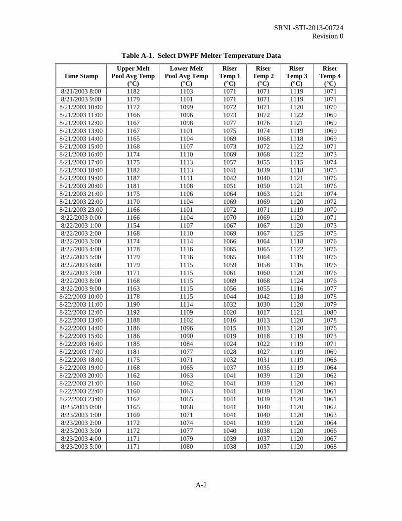
2.4 DWPF Melter 2 Crystallization Issues and Analyses DWPF Melter 2 began operation in March 2003. About 5 months later (August 28, 2003), glass was sampled from DWPF Melter 2 at three locations: a pour stream sample during processing of Sludge Batch 2 (collected at approximately 7:50 PM on August 28, 2003), a sample scraped from the 2 inch upper pour spout bore while hot, and a sample that had spalled off of a pour spout insert after the insert had cooled. A detailed analysis of these samples is provided by Jantzen, et al.15 Select DWPF melter pool and riser temperature data for a time period of about one week prior to collection of the pour stream sample are included for reference as Appendix A. The sampling date corresponded to approximately five months of operation of DWPF Melter 2, at a time when the targeted waste loading had been increased to 38 wt % and the new quasi-crystalline liquidus model had been implemented.3,6 An unusual amount of crystallization in the pour spout was hindering processing. The upper pour spout bore sample was determined to be about 62% glass, with the remaining fraction consisting of trevorite, NiCr2O4, and noble metal oxides. The pour spout insert sample contained less spinel, but more Cr2O3, which was posited to be due to oxidation of the Inconel® 690 and reaction with the glass.15 The pour stream sample was shown to be amorphous via XRD. The predicted liquidus temperature of the pour stream sample, based on its measured composition, was 997 °C. Jantzen, et al. describe several potential mechanisms for the accumulation of crystals (including noble metal oxides) in the DWPF melter pour spout, including temperature and oxygen fugacity gradients, heat sink induced crystallization, Inconel® 690 oxidation, and elevated concentrations of Cr2O3 in the pour stream glass due to Monofrax K-3 corrosion. Heat sink induced crystallization was shown to be the most likely mechanism.15
2.5 DWPF Melter Pour Stream Sample Analyses Several glass pour stream samples have been collected and analyzed at SRNL during the operation of the DWPF melter. While these analyses have focused on determining the glass composition, radionuclide inventory, and chemical durability in order to meet regulatory requirements, some basic characterization related to crystallization was also completed. In general, contained scanning electron microscopy with energy dispersive spectroscopy (CSEM/EDS) was used to observe small samples of the pour stream glasses and identify any crystalline phases. No spinels were observed in any of the pour stream glasses. Small crystals consisting of the noble metals ruthenium, rhodium, and palladium were identified in several of the pour stream glasses. It is important to note that the volume fraction of crystals observed in these glasses was exceedingly small in all cases and was not determined quantitatively. Also, both the waste loading and noble metals concentration in the melter feed were higher in those

SRNL-STI-2013-00724 Revision 0
11
batches where noble metals were observed in the pour stream samples. A summary of the observed crystallization in the pour stream glasses is given in Table 2-1.
Table 2-1. Summary of Crystallization Data from DWPF Pour Stream Sample Analyses.
DWPF Melter
DWPF Sludge Batch
Crystallization Detected in Pour
Stream Glass Detection Method Reference
Melter 1
Sludge Batch 1a
(Canister 50) None CSEM/EDS 39
Sludge Batch 1a
(Canister 61) None CSEM/EDS 40
Sludge Batch 1a
(Canister 409) None CSEM/EDS 41
Sludge Batch 1b None CSEM/EDS 42
Melter 2
Sludge Batch 2 None Visual observation 43
Sludge Batch 3
Ruthenium, rhodium, and
palladium crystals CSEM/EDS 44
Sludge Batch 4 Ruthenium crystals CSEM/EDS 45
Sludge Batch 5 Ruthenium crystals CSEM/EDS 45
Sludge Batch 6
Ruthenium crystals XRD 46 Ruthenium and
palladium crystals CSEM/EDS
Sludge Batch 7a
Ruthenium and rhodium crystals CSEM/EDS 47
Sludge Batch 7b
Ruthenium and rhodium crystals CSEM/EDS 48
2.6 Suspension of Spinels in the DWPF Melter A simple computational study was performed to determine whether settled spinels in the DWPF melter could be expected to become re-suspended as a result of convection currents in the melt pool and flow through the riser.49 The study used a fluid mechanics model to evaluate the propensity for suspending spinel crystals in the melt pool and sweeping them out through the riser. While admittedly simple in nature, the calculations suggested that spinels (assumed to be spherical particles 20 µm in diameter) may be suspended in the melt pool and carried through the riser during pouring.49
3.0 DWPF Melter 2 Operating Data Melter idle time is a critical factor in developing and implementing a crystal tolerant approach to melter operation. Idle periods, assuming that agitation of the melt pool is minimal during these times and that the melter has been operated at or below the TL of the glass, provide the most opportune time for crystal growth and settling. Example data on actual attainment of the DWPF

SRNL-STI-2013-00724 Revision 0
12
melter for fiscal years 2011 and 2012 were provided by DWPF engineering.a These data are presented here as an example of what might be expected in terms of the actual attainment of the WTP HLW melter (i.e., under prototypical conditions), and in turn, the melt pool idling time that might be expected in a year. Note that bubblers were operational in the DWPF melter during these operating periods (see Table 2-1), although the bubbling rate is reduced to a minimum during idle periods as idle periods are associated with increased vaporization of alkali borates from the melt pool.50 DWPF melter attainment (i.e., the amount of time during which feed was supplied to the melter) for FY2011 was approximately 67%. Feeding was stopped for approximately 2,870 hours at various intervals over the course of FY2011. A summary of the FY2011 melter downtime events is provided in Table 3-1. DWPF melter attainment for FY2012 was approximately 66%. Feeding was stopped for approximately 3,030 hours. A summary of the FY2012 melter downtime events is provided in Table 3-2. A review of these tables shows that planned and unplanned outages occur for durations of days up to several weeks. Time periods on this scale must be considered as part of the development of the crystal tolerant strategy. DWPF was in an extended outage from early October to late December 2013. This was a unique situation for sampling the melter after an extended idling period.51 Samples were successfully collected from the melter pour stream when processing resumed. Characterization will be performed to determine the type and extent of crystallization, if any. These results will be coupled with composition data to provide an additional input to development of the crystal-tolerant glass strategy.
a Email communication from Brandon Hodges, Savannah River Remediation, June 5, 2013.

SRNL-STI-2013-00724 Revision 0
13
Table 3-1. Fiscal Year 2011 DWPF Melter Downtime Key Event Timeline.
Dates Type of Outage Description
11/06/10 – 11/10/10 Unscheduled Maintenance Shutdown due to lack of space to store filled canisters. Repairs made to Canister Decontamination Chamber #2 in order to blast canisters and generate space for filled canisters.
11/14/10 – 11/19/10 Unscheduled Maintenance Shutdown due to lack of space to store filled canisters. Replaced the wire rope on the in-cell crane for the Canister Decontamination Cell, existing wire rope had a kink that would not pass through the load block.
12/03/10 – 12/07/10 Unscheduled Maintenance
Trouble restarting the Melter feed loop after a scheduled heated bellows liner replacement. Troubleshooting and repair were performed to put feed loop back in service. Issue resolved by replacing the section of the feed loop jumper between the flow meter and the Hanford wall nozzle.
01/04/11 – 01/07/11 Planned Outage Visual inspection of the Melter bubblers.
01/26/11 – 01/30/11 Scheduled Maintenance Replacement of the Melter Primary Off-Gas (POG) quencher and film cooler.
02/28/11 – 03/05/11 Slurry Mix Evaporator (SME) Transfer Delay
Delay in SME batch transfer to Melter Feed Tank (MFT). Clogged sample line caused issues getting the SME product sample to the lab for analysis.
03/20/11 – 03/26/11 SME Transfer Delay Delay in SME batch transfer to MFT. Replacement of Sludge Receipt and Adjustment Tank (SRAT) transfer pump delayed SME processing. In addition, SME processing delayed due to SME GC #2 column replacement.
03/27/11 – 03/31/11 Shutdown Delay in Chemical Processing Cell (CPC).

SRNL-STI-2013-00724 Revision 0
14
Table 3-1. Fiscal Year 2011 DWPF Melter Downtime Key Event Timeline. (continued)
Dates Type of Outage Description
04/01/11 – 04/29/11 Planned Outage Site steam outage, Load Center B7 work, replaced Melter POG quencher and high efficiency mist eliminator filters, replaced Melter bubblers.
05/24/11 – 05/31/11 SME Transfer Delay Delay in SME batch transfer to MFT. SME vessel would not steam properly. Replaced steam traps and re-gasketed various SME steam supply jumpers along with other troubleshooting activities.
06/07/11 – 06/14/11 Unscheduled Maintenance SME coil replacement.

SRNL-STI-2013-00724 Revision 0
15
Table 3-2. Fiscal Year 2012 DWPF Melter Downtime Key Event Timeline.
Dates Type of Outage Description
10/16/11 – 11/03/11 Planned Outage Cleaned Melter off-gas condensate tank, installed new heated bellows liner and pour spout insert, cleaned Melter Off-gas Quencher.
11/07/12 – 11/18/11 SME Transfer Delay Complete outage activities in the CPC.
02/06/12 – 02/09/12 Unscheduled Maintenance Replace SME coil, repair SME agitator electrical jumper.
06/26/12 – 07/02/12 SME Transfer Delay Waiting on SME Batch 639 to transfer; process frit line plugged (cleared line and replaced components), replaced SME Hydraguard sampler, remediated batch due to failed flammability constraint.
07/28/12 – 08/24/12 SME Transfer Delay Processing in CPC on hold.
09/03/12 – 09/20/12 SME Transfer Delay Waiting on SME Batch 645 to transfer; cleared SME sample line trickle flow piping, replaced flow element in trickle flow piping, replaced SME Hydraguard sample pump.

SRNL-STI-2013-00724 Revision 0
16
4.0 Summary A road mapa was recently developed to guide research and development efforts for a crystal tolerant glass processing strategy for WTP. The basis of this alternative approach is an empirical model predicting the crystal accumulation in the WTP glass discharge riser and melter bottom as a function of glass composition, time, and temperature. When coupled with an associated operating limit, this model could then be integrated into the process control algorithms to formulate crystal tolerant HLW glasses targeting higher waste loadings while still meeting process related limits and melter lifetime expectancies. This report provides a review of the scaled melter testing that was completed in support of DWPF development, a review of the crystallization observed with the full scale DWPF melters, and examples of actual DWPF melter attainment in recent years. The intent is to provide an overview of lessons learned, including some example data, that can be used to advance the development and implementation of an empirical model and operating limit for crystal accumulation for WTP. Operation of the first and second (current) DWPF melters has demonstrated that the strategy of using a liquidus temperature predictive model combined with a 100 °C offset from the normal melter temperature of 1150 °C (i.e., the predicted TL of the glass must be 1050 °C or less) has been successful in preventing any detrimental accumulation of spinel in the melt pool, and spinel has not been observed in any of the DWPF pour stream glass samples. Spinel was observed at the bottom of DWPF Melter 1 as a result of K-3 refractory corrosion. Issues have occurred with accumulation of spinel in the pour spout during periods of operation at higher waste loadings. Given that both DWPF melters were or have been in operation for greater than 8 years, the service life of the melters has far exceeded design expectations. It is possible that the DWPF liquidus temperature approach is conservative, in that it may be possible to successfully operate the melter with a small degree of allowable crystallization in the glass. This could be a viable approach to increasing waste loading in the glass assuming that the crystals are suspended in the melt and swept out through the riser and pour spout. Additional study is needed, and development work for WTP might be leveraged to support a different operating limit for the DWPF. The DWPF liquidus temperature strategy is geared specifically toward bulk crystallization within the melt pool. Crystallization issues in the pour spout have occurred in the past as a result of temperature gradients or heat sinks in the pour spout. As recommended below, these conditions should be considered in developing the crystal tolerant strategy for WTP. Several recommendations are made regarding considerations that need to be included as part of the WTP crystal tolerant strategy based on the DWPF development work and operational data reviewed here. These include:
• Identify and consider the impacts of potential heat sinks in the WTP melter and glass pouring system
• Consider the contributions of refractory corrosion products, which may serve to nucleate additional crystals leading to further accumulation
• Consider volatilization of components from the melt (e.g., boron, alkali, halides, etc.) and determine their impacts on glass crystallization behavior
• Evaluate the impacts of glass REDOX conditions and the distribution of temperature within the WTP melt pool and melter pour chamber on crystal accumulation rate
• Consider the impact of precipitated crystals on glass viscosity
a Matyáš, J., J. D. Vienna, D. K. Peeler, K. M. Fox, and C. C. Herman, “Road Map for Development of Crystal-Tolerant High Level Waste Glasses,” SRNL-STI-2013-00734, in draft.

SRNL-STI-2013-00724 Revision 0
17
• Consider the impact of an accumulated crystalline layer on thermal convection currents and bubbler effectiveness within the melt pool
• Evaluate the impact of spinel accumulation on Joule heating of the WTP melt pool • Include noble metals in glass melt experiments because of their potential to act as
nucleation sites for spinel crystallization

SRNL-STI-2013-00724 Revision 0
18
5.0 References 1. Vienna, J. D., D. C. Skorski, D. S. Kim, and J. Matyáš, “Glass Property Models and Constraints for Estimating the Glass to be Produced at Hanford by Implementing Current Advanced Glass Formulation Efforts,” U.S. Department of Energy Report EWG-RPT-003, Revision 0, Pacific Northwest National Laboratory, Richland, WA (2013). 2. Belsher, J. D. and F. L. Meinert, “High-Level Waste Glass Formulation Model Sensitivity Study 2009 Glass Formulation Model Versus 1996 Glass Formulation Model,” U.S. Department of Energy Report RPP-RPT-42649, Revision 0, Washington River Protection Solutions, Richland, Washington (2009). 3. Jantzen, C. M. and K. G. Brown, “Predicting the Spinel-Nepheline Liquidus for Application to Nuclear Waste Glass Processing. Part I: Primary Phase Analysis, Liquidus Measurement, and Quasicrystalline Approach,” Journal of the American Ceramic Society, 90 [6] 1866-1879 (2007). 4. Vienna, J. D. and D. S. Kim, “Preliminary IHLW Formulation Algorithm Description,” U.S. Department of Energy Report 24590-HLW-RPT-RT-05-001, Revision 0, River Protection Project, Hanford Tank Waste Treatment and Immobilization Plant, Richland, Washington (2008). 5. Brown, K. G., C. M. Jantzen, and G. Ritzhaupt, “Relating Liquidus Temperature to Composition for Defense Waste Processing Facility (DWPF) Process Control,” U.S. Department of Energy Report WSRC-TR-2001-00520, Revision 0, Westinghouse Savannah River Company, Aiken, SC (2001). 6. Jantzen, C. M. and K. G. Brown, “Predicting the Spinel-Nepheline Liquidus for Application to Nuclear Waste Glass Processing. Part II: Quasicrystalline Freezing Point Depression Model,” Journal of the American Ceramic Society, 90 [6] 1880-1891 (2007). 7. Edwards, T. B., K. G. Brown, and R. L. Postles, “SME Acceptability Determination for DWPF Process Control,” U.S. Department of Energy Report WSRC-TR-95-00364, Revision 5, Washington Savannah River Company, Aiken, SC (2006). 8. Smith, M. E. and J. E. Occhipinti, “Engineering Position: DWPF Melter Life Assessment,” U.S. Department of Energy Memorandum SRR-WSE-2010-00109, Savannah River Remediation, Aiken, SC (2011). 9. Matyáš, J., J. D. Vienna, A. Kimura, M. Schaible, and R. M. Tate, “Development of Crystal-Tolerant Waste Glasses”; pp. 41-51 in Ceramic Transactions, Vol. 222, Advances in Materials Science for Environmental and Nuclear Technology. Edited by K. M. Fox, E. N. Hoffman, N. Manjooran and G. Pickrell. John Wiley & Sons, Inc., Hoboken, NJ, 2010. 10. Bickford, D. F. and C. M. Jantzen, “Devitrification of SRL Defense Waste Glass”; pp. 557-565 in Scientific Basis for Nuclear Waste Management VII. Edited by G. L. McVay. Elsevier, New York, 1984. 11. Vienna, J. D., D. S. Kim, M. J. Schweiger, J. S. McCloy, J. Matyáš, G. F. Piepel, and S. K. Cooley, “Test Plan: Enhanced Hanford Waste Glass Models,” U.S. Department of Energy Report TP-EWG-00001, Revision 0, Pacific Northwest National Laboratory, Richland, WA (2013).

SRNL-STI-2013-00724 Revision 0
19
12. Muller, I. S., I. L. Pegg, and I. Joseph, “Test Plan: Enhanced LAW Glass Property-Composition Models, Phase 2,” U.S. Department of Energy Report VSL-13T3050-1, Revision 0, Vitreous State Laboratory, Washington, DC (2013). 13. Matyáš, J., A. R. Huckleberry, C. P. Rodriguez, J. B. Lang, A. T. Owen, and A. A. Kruger, “Empirical Model for Formulation of Crystal-Tolerant HLW Glasses”; pp. 121-128 in Ceramic Transactions, Vol. 236, Advances in Materials Science for Environmental and Energy Technologies. Edited by T. Ohji, M. Singh, E. Hoffman, M. Seabaugh and G. Yang. John Wiley & Sons, Inc., Hoboken, NJ, 2012. 14. Fox, K. M. and D. K. Peeler, “Task Technical and Quality Assurance Plan for Hanford HLW Glass Development and Characterization,” U.S. Department of Energy Report SRNL-RP-2013-00692, Revision 0, Savannah River National Laboratory, Aiken, SC (2013). 15. Jantzen, C. M., A. D. Cozzi, and N. E. Bibler, “Characterization of Defense Waste Processing Facility (DWPF) Glass and Deposit Samples from Melter #2,” U.S. Department of Energy Report WSRC-TR-2003-00504, Revision 0, Savannah River Technology Center, Aiken, SC (2004). 16. Iverson, D. C., “DWPF Glass Melter Technology Manual,” U.S. Department of Energy Report WSRC-TR-93-587, Volumes 1-4, Westinghouse Savannah River Company, Aiken, SC (1993). 17. Rankin, W. N., P. E. O'Rourke, P. D. Soper, M. B. Cosper, and B. C. Osgood, “Evaluation of Corrosion and Deposition in the 1941 Melter,” U.S. Department of Energy Report DPST-82-231, E. I du Pont de Nemours & Co., Savannah River Laboratory, Aiken, SC (1982). 18. Routt, K. R., “Comments on the Electrode Configuration for the DWPF Melter,” U.S. Department of Energy Report DPST-82-264, Savannah River Laboratory, Aiken, SC (1982). 19. Allen, T. L., D. C. Iverson, and M. J. Plodinec, “History of the Small Cylindrical Melter,” U.S. Department of Energy Report DP-1676, E. I du Pont de Nemours & Co., Savannah River Laboratory, Aiken, SC (1985). 20. Plodinec, M. J. and K. R. Routt, “Performance of Structural and Active Components of the Small-Scale Cylindrical Melter: First Operating Campaign,” U.S. Department of Energy Report DPST-80-494, E. I du Pont de Nemours & Co., Savannah River Laboratory, Aiken, SC (1980). 21. Routt, K. R., M. J. Plodinec, and M. A. Porter, “Performance of Structural and Active Components of the Small Cylindrical Melter: Second Operating Campaign.,” U.S. Department of Energy Report DPST-80-654, E. I du Pont de Nemours & Co., Savannah River Laboratory, Aiken, SC (1980). 22. Jantzen, C. M., “Lack of Slag Formation in the Scale Glass Melter,” U.S. Department of Energy Report DPST-87-373, E. I du Pont de Nemours & Co., Savannah River Laboratory, Aiken, SC (1987). 23. Iverson, D. C. and D. F. Bickford, “Evaluation of Materials Performance in a Large-Scale Glass Melter After Two Years of Vitrifying Simulated SRP Defense Waste”; pp. 839-845 in Materials Research Society Symposium Proceedings, Vol. 44, Scientific Basis for Nuclear Waste

SRNL-STI-2013-00724 Revision 0
20
Management VIII. Edited by C. M. Jantzen, J. A. Stone and R. C. Ewing. Materials Research Society, Pittsburgh, PA, 24. Colven, W. P., D. M. Sabatino, J. L. Kessler, and H. C. Wolf, “Summary of the Fifth Run of the Large Slurry-Fed Melter,” U.S. Department of Energy Report DPST-82-890, E.I. duPont deNemours & Co., Savannah River Laboratory, Aiken, SC (1984). 25. Mahoney, J. L. and A. F. Weisman, “Failure of the Riser Heater in the DWPF Scale Glass Melter,” U.S. Department of Energy Report DPST-85-734, E. I du Pont de Nemours & Co., Savannah River Laboratory, Aiken, SC (1985). 26. Baron, M. R. and M. E. Smith, “Summary of the Drain and Restart of the DWPF Scale Glass Melter,” U.S. Department of Energy Report DPST-88-481, E. I du Pont de Nemours & Co., Savannah River Laboratory, Aiken, SC (1988). 27. Jantzen, C. M., “Devitrification of Scale Melter Glass in Riser Heater,” U.S. Department of Energy Report DPST-86-461, E. I du Pont de Nemours & Co., Savannah River Laboratory, Aiken, SC (1986). 28. Weisman, A. F., “DWPF Scale Melter Glass Pouring Studies,” U.S. Department of Energy Report DPST-86-862, E. I du Pont de Nemours & Co., Savannah River Laboratory, Aiken, SC (1986). 29. Smith, M. E., N. D. Hutson, D. H. Miller, J. Morrison, H. Shah, J. A. Shuford, J. Glascock, F. H. Wurzinger, and J. R. Zamecnik, “Checkout and Start-Up of the Integrated DWPF Melter System,” U.S. Department of Energy Report WSRC-RP-89-321, Westinghouse Savannah River Company, Savannah River Laboratory, Aiken, SC (1989). 30. Hutson, N. D., “Integrated DWPF Melter System (IDMS) Campaign Report: Hanford Waste Vitrification Plant (HWVP) Process Demonstration,” U.S. Department of Energy Report WSRC-TR-92-0403, Revision 1, Westinghouse Savannah River Company, Savannah River Technology Center, Aiken, SC (1993). 31. Bickford, D. F. and M. E. Smith, “The Behavior and Effects of the Noble Metals in the DWPF Melter System,” U.S. Department of Energy Report WSRC-TR-97-00370, Revision 0, Westinghouse Savannah River Company, Savannah River Technology Center, Aiken, SC (1997). 32. Jantzen, C. M. and D. P. Lambert, “Inspection and Analysis of the Integrated DWPF Melter System (IDMS) After Seven Years of Continuous Operation”; pp. 1-11 in Ceramic Transactions, Vol. 107, Environmental Issues and Waste Management Technologies in the Ceramic and Nuclear Industries, V. Edited by G. T. Chandler and X. Feng. The American Ceramic Society, Westerville, OH, 2000. 33. Jantzen, C. M., K. G. Brown, K. J. Imrich, and J. B. Pickett, “High Cr2O3 Refractory Corrosion in Oxidizing Melter Feeds: Relevance to Nuclear and Hazardous Waste Vitrification”; pp. 203-212 in Ceramic Transactions, Vol. 93, Environmental Issues and Waste Management Technologies in the Ceramic and Nuclear Industries, Vol. IV. Edited by J. C. Marra and G. T. Chandler. The American Ceramic Society, Westerville, OH, 1999. 34. Jantzen, C. M., K. G. Brown, K. J. Imrich, and J. B. Pickett, “High Chrome Refractory Characterization: Part I. Impact of Melt REDuction/OXidation (Redox) on the Corrosion

SRNL-STI-2013-00724 Revision 0
21
Mechanism in Radioactive Waste Glass Melters,” International Journal of Applied Glass Science, [to be submitted] (2014). 35. Jantzen, C. M., K. G. Brown, K. J. Imrich, and J. B. Pickett, “High Chrome Refractory Characterization: Part II. Accumulation of Spinel Corrosion Deposits in Radioactive Waste Glass Melters,” International Journal of Applied Glass Science, [to be submitted] (2014). 36. Iverson, D. C., K. J. Imrich, D. F. Bickford, J. T. Gee, C. F. Jenkins, and F. M. Heckendorn, “Examination of DWPF Melter Materials After 8 Years of Service,” U.S. Department of Energy Report WSRC-MS-2003-00318, Washington Savannah River Company, Aiken, SC (2003). 37. Jones, R. T., “DWPF Melter Pour Stream Anomaly-3/96 Investigation Compendium,” U.S. Department of Energy Memorandum HLW-APA-960027, Revision 1, Westinghouse Savannah River Company, Aiken, SC (1996). 38. Cozzi, A. D. and J. M. Pareizs, “Characterization of DWPF Melter One Glasses,” U.S. Department of Energy Report WSRC-TR-2003-00477, Revision 0, Savannah River Technology Center, Westinghouse Savannah River Company, Aiken, SC (2003). 39. Bibler, N. E., T. L. Fellinger, and O. B. Hodoh, “DWPF Glass Results for the Analysis of a Pour Stream Sample Taken During Pouring of the 50th Canister (Canister S00471),” U.S. Department of Energy Report WSRC-RP-98-00053, Revision 0, Westinghouse Savannah River Company, Savannah River Technology Center, Aiken, SC (1998). 40. Bibler, N. E., T. L. Fellinger, and O. B. Hodoh, “DWPF Glass Results for the Analysis of a Pour Stream Sample Taken During Pouring of the 61st Canister (Canister S00482),” U.S. Department of Energy Report WSRC-RP-98-00054, Revision 0, Westinghouse Savannah River Company, Savannah River Technology Center, Aiken, SC (1998). 41. Fellinger, T. L. and N. E. Bibler, “DWPF Glass Results for the Analysis of a Pour Stream Sample Taken During Pouring of the 409th Canister (Canister S00834) in Macrobatch 1,” U.S. Department of Energy Report WSRC-RP-98-01400, Revision 0, Westinghouse Savannah River Company, Savannah River Technology Center, Aiken, SC (1999). 42. Fellinger, T. L. and N. E. Bibler, “Results of the Chemical Composition and the Product Consistency Test for the DWPF Macro Batch 2 Glass Pour Stream Sample Taken During the Pouring of Canister S01142,” U.S. Department of Energy Report WSRC-RP-2000-00281, Revision 0, Westinghouse Savannah River Company, Savannah River Technology Center, Aiken, SC (2000). 43. Cozzi, A. D., N. E. Bibler, and C. J. Bannochie, “Analytical Results of DWPF Glass Sample Taken During Filling of Canister S01913,” U.S. Department of Energy Report WSRC-TR-2004-00316, Revision 2, Washington Savannah River Company, Savannah River National Laboratory, Aiken, SC (2005). 44. Bannochie, C. J. and N. E. Bibler, “Analysis of Sludge Batch 3 (Macrobatch 4) DWPF Pour Stream Glass Sample for Canister S02312,” U.S. Department of Energy Report WSRC-TR-2005-00354, Revision 0, Washington Savannah River Company, Savannah River National Laboratory, Aiken, SC (2005).

SRNL-STI-2013-00724 Revision 0
22
45. Reigel, M. M. and N. E. Bibler, “Analysis of Sludge Batch 4 (Macrobatch 5) for Canister S02902 and Sludge Batch 5 (Macrobatch 6) for Canister S03317 DWPF Pour Stream Glass Samples,” U.S. Department of Energy Report SRNL-STI-2010-00435, Revision 0, Savannah River Nuclear Solutions, Savannah River National Laboratory, Aiken, SC (2010). 46. Johnson, F. C., “Analysis of DWPF Sludge Batch 6 (Macrobatch 7) Pour Stream Glass Samples,” U.S. Department of Energy Report SRNL-STI-2011-00555, Revision 0, Savannah River Nuclear Solutions, Savannah River National Laboratory, Aiken, SC (2012). 47. Johnson, F. C. and J. M. Pareizs, “Analysis of DWPF Sludge Batch 7a (Macrobatch 8) Pour Stream Samples,” U.S. Department of Energy Report SRNL-STI-2012-00017, Revision 1, Savannah River Nuclear Solutions, Savannah River National Laboratory, Aiken, SC (2012). 48. Johnson, F. C., C. L. Crawford, and J. M. Pareizs, “Analysis of the Sludge Batch 7b (Macrobatch 9) DWPF Pour Stream Glass Sample,” U.S. Department of Energy Report SRNL-STI-2013-00462, Revision 0, Savannah River Nuclear Solutions, Savannah River National Laboratory, Aiken, SC (2013). 49. Hardy, B. J., “Transport and Suspension of Spinels in the DWPF Melter,” U.S. Department of Energy Report SRT-PTD-97-0014, Revision 0, Westinghouse Savannah River Company, Savannah River Technology Center, Aiken, SC (1997). 50. Jantzen, C. M., “Glass Melter Off-Gas System Pluggages: Cause, Significance, and Remediation,” U.S. Department of Energy Report WSRC-TR-90-205, Revision 0, Westinghouse Savannah River Company, Aiken, SC (1991). 51. Fox, K. M. and D. K. Peeler, “SRNL Request for DWPF Pour Stream Sampling Upon Restart After Extended Outage,” U.S. Department of Energy Memorandum SRNL-L3100-2013-00214, Savannah River National Laboratory, Aiken, SC (2013).

SRNL-STI-2013-00724 Revision 0
A-1
Appendix A. DWPF Melter Temperature Data for Selected Times during August 2003
SRNL-STI-2013-00724 Revision 0
A-2
Table A-1. Select DWPF Melter Temperature Data
Time Stamp Upper Melt
Pool Avg Temp (°C)
Lower Melt Pool Avg Temp
(°C)
Riser Temp 1
(°C)
Riser Temp 2
(°C)
Riser Temp 3
(°C)
Riser Temp 4
(°C) 8/21/2003 8:00 1182 1103 1071 1071 1119 1071 8/21/2003 9:00 1179 1101 1071 1071 1119 1071
8/21/2003 10:00 1172 1099 1072 1071 1120 1070 8/21/2003 11:00 1166 1096 1073 1072 1122 1069 8/21/2003 12:00 1167 1098 1077 1076 1121 1069 8/21/2003 13:00 1167 1101 1075 1074 1119 1069 8/21/2003 14:00 1165 1104 1069 1068 1118 1069 8/21/2003 15:00 1168 1107 1073 1072 1122 1071 8/21/2003 16:00 1174 1110 1069 1068 1122 1073 8/21/2003 17:00 1175 1113 1057 1055 1115 1074 8/21/2003 18:00 1182 1113 1041 1039 1118 1075 8/21/2003 19:00 1187 1111 1042 1040 1121 1076 8/21/2003 20:00 1181 1108 1051 1050 1121 1076 8/21/2003 21:00 1175 1106 1064 1063 1121 1074 8/21/2003 22:00 1170 1104 1069 1069 1120 1072 8/21/2003 23:00 1166 1101 1072 1071 1119 1070 8/22/2003 0:00 1166 1104 1070 1069 1120 1071 8/22/2003 1:00 1154 1107 1067 1067 1120 1073 8/22/2003 2:00 1168 1110 1069 1067 1125 1075 8/22/2003 3:00 1174 1114 1066 1064 1118 1076 8/22/2003 4:00 1178 1116 1065 1065 1122 1076 8/22/2003 5:00 1179 1116 1065 1064 1119 1076 8/22/2003 6:00 1179 1115 1059 1058 1116 1076 8/22/2003 7:00 1171 1115 1061 1060 1120 1076 8/22/2003 8:00 1168 1115 1069 1068 1124 1076 8/22/2003 9:00 1163 1115 1056 1055 1116 1077
8/22/2003 10:00 1178 1115 1044 1042 1118 1078 8/22/2003 11:00 1190 1114 1032 1030 1120 1079 8/22/2003 12:00 1192 1109 1020 1017 1121 1080 8/22/2003 13:00 1188 1102 1016 1013 1120 1078 8/22/2003 14:00 1186 1096 1015 1013 1120 1076 8/22/2003 15:00 1186 1090 1019 1018 1119 1073 8/22/2003 16:00 1185 1084 1024 1022 1119 1071 8/22/2003 17:00 1181 1077 1028 1027 1119 1069 8/22/2003 18:00 1175 1071 1032 1031 1119 1066 8/22/2003 19:00 1168 1065 1037 1035 1119 1064 8/22/2003 20:00 1162 1063 1041 1039 1120 1062 8/22/2003 21:00 1160 1062 1041 1039 1120 1061 8/22/2003 22:00 1160 1063 1041 1039 1120 1061 8/22/2003 23:00 1162 1065 1041 1039 1120 1061 8/23/2003 0:00 1165 1068 1041 1040 1120 1062 8/23/2003 1:00 1169 1071 1041 1040 1120 1063 8/23/2003 2:00 1172 1074 1041 1039 1120 1064 8/23/2003 3:00 1172 1077 1040 1038 1120 1066 8/23/2003 4:00 1171 1079 1039 1037 1120 1067 8/23/2003 5:00 1171 1080 1038 1037 1120 1068

SRNL-STI-2013-00724 Revision 0
A-3
Table A-1. Select DWPF Melter Temperature Data (continued)
Time Stamp Upper Melt
Pool Avg Temp (°C)
Lower Melt Pool Avg Temp
(°C)
Riser Temp 1
(°C)
Riser Temp 2
(°C)
Riser Temp 3
(°C)
Riser Temp 4
(°C) 8/23/2003 6:00 1171 1081 1038 1036 1120 1070 8/23/2003 7:00 1170 1081 1037 1035 1120 1070 8/23/2003 8:00 1170 1082 1036 1034 1120 1070 8/23/2003 9:00 1169 1083 1035 1033 1120 1070
8/23/2003 10:00 1169 1084 1035 1033 1120 1070 8/23/2003 11:00 1170 1086 1035 1033 1120 1070 8/23/2003 12:00 1170 1087 1034 1032 1121 1070 8/23/2003 13:00 1170 1088 1034 1032 1121 1071 8/23/2003 14:00 1155 1090 1036 1034 1121 1071 8/23/2003 15:00 1162 1092 1055 1053 1125 1071 8/23/2003 16:00 1170 1096 1064 1063 1124 1072 8/23/2003 17:00 1170 1100 1067 1066 1120 1073 8/23/2003 18:00 1184 1105 1056 1055 1116 1074 8/23/2003 19:00 1191 1101 1042 1040 1117 1075 8/23/2003 20:00 1198 1096 1036 1034 1119 1076 8/23/2003 21:00 1195 1092 1031 1029 1120 1077 8/23/2003 22:00 1187 1086 1028 1025 1120 1075 8/23/2003 23:00 1177 1081 1030 1028 1120 1073 8/24/2003 0:00 1167 1075 1033 1032 1120 1071 8/24/2003 1:00 1165 1074 1036 1035 1120 1069 8/24/2003 2:00 1163 1075 1039 1038 1120 1067 8/24/2003 3:00 1164 1075 1040 1038 1120 1066 8/24/2003 4:00 1165 1076 1040 1038 1120 1067 8/24/2003 5:00 1167 1077 1039 1037 1120 1067 8/24/2003 6:00 1169 1078 1038 1036 1120 1068 8/24/2003 7:00 1170 1079 1037 1036 1120 1069 8/24/2003 8:00 1172 1080 1037 1035 1120 1070 8/24/2003 9:00 1172 1081 1036 1034 1120 1071
8/24/2003 10:00 1172 1082 1035 1033 1120 1071 8/24/2003 11:00 1172 1083 1035 1033 1120 1072 8/24/2003 12:00 1172 1084 1034 1032 1120 1072 8/24/2003 13:00 1172 1085 1034 1032 1120 1072 8/24/2003 14:00 1172 1086 1033 1032 1120 1073 8/24/2003 15:00 1172 1087 1033 1031 1120 1073 8/24/2003 16:00 1172 1087 1033 1031 1120 1073 8/24/2003 17:00 1172 1088 1032 1030 1120 1073 8/24/2003 18:00 1171 1089 1032 1030 1120 1074 8/24/2003 19:00 1172 1090 1032 1030 1120 1074 8/24/2003 20:00 1172 1091 1033 1031 1120 1073 8/24/2003 21:00 1172 1091 1034 1032 1121 1073 8/24/2003 22:00 1163 1092 1044 1043 1122 1073 8/24/2003 23:00 1167 1093 1063 1062 1123 1072 8/25/2003 0:00 1173 1095 1072 1071 1123 1072 8/25/2003 1:00 1177 1098 1075 1073 1122 1072 8/25/2003 2:00 1176 1100 1075 1074 1121 1072 8/25/2003 3:00 1165 1103 1073 1073 1120 1071 8/25/2003 4:00 1175 1105 1072 1071 1119 1071

SRNL-STI-2013-00724 Revision 0
A-4
Table A-1. Select DWPF Melter Temperature Data (continued)
Time Stamp Upper Melt
Pool Avg Temp (°C)
Lower Melt Pool Avg Temp
(°C)
Riser Temp 1
(°C)
Riser Temp 2
(°C)
Riser Temp 3
(°C)
Riser Temp 4
(°C) 8/25/2003 5:00 1180 1108 1070 1069 1119 1071 8/25/2003 6:00 1178 1108 1068 1067 1119 1071 8/25/2003 7:00 1177 1106 1068 1067 1118 1071 8/25/2003 8:00 1179 1103 1068 1068 1118 1071 8/25/2003 9:00 1183 1101 1063 1062 1115 1071
8/25/2003 10:00 1184 1097 1050 1049 1116 1071 8/25/2003 11:00 1186 1092 1046 1045 1121 1073 8/25/2003 12:00 1182 1087 1042 1040 1120 1073 8/25/2003 13:00 1162 1084 1040 1039 1119 1071 8/25/2003 14:00 1157 1083 1054 1053 1121 1070 8/25/2003 15:00 1162 1084 1071 1070 1123 1068 8/25/2003 16:00 1173 1086 1072 1072 1120 1066 8/25/2003 17:00 1179 1088 1062 1060 1117 1067 8/25/2003 18:00 1180 1086 1054 1052 1117 1068 8/25/2003 19:00 1180 1083 1049 1047 1119 1070 8/25/2003 20:00 1188 1080 1044 1042 1120 1071 8/25/2003 21:00 1185 1076 1040 1038 1120 1071 8/25/2003 22:00 1179 1073 1040 1038 1120 1069 8/25/2003 23:00 1174 1070 1040 1039 1120 1068 8/26/2003 0:00 1168 1066 1041 1039 1120 1067 8/26/2003 1:00 1166 1065 1041 1040 1120 1066 8/26/2003 2:00 1167 1067 1042 1040 1120 1065 8/26/2003 3:00 1167 1068 1042 1041 1120 1063 8/26/2003 4:00 1168 1069 1043 1041 1120 1064 8/26/2003 5:00 1168 1071 1043 1041 1120 1064 8/26/2003 6:00 1169 1072 1042 1041 1120 1065 8/26/2003 7:00 1170 1073 1042 1040 1120 1066 8/26/2003 8:00 1170 1074 1041 1039 1120 1067 8/26/2003 9:00 1171 1075 1040 1038 1120 1067
8/26/2003 10:00 1171 1076 1040 1038 1120 1068 8/26/2003 11:00 1172 1077 1039 1037 1120 1069 8/26/2003 12:00 1171 1077 1038 1036 1120 1069 8/26/2003 13:00 1171 1078 1037 1036 1120 1069 8/26/2003 14:00 1171 1079 1037 1035 1120 1069 8/26/2003 15:00 1171 1080 1037 1035 1120 1069 8/26/2003 16:00 1171 1080 1037 1035 1120 1069 8/26/2003 17:00 1171 1080 1036 1035 1120 1069 8/26/2003 18:00 1170 1080 1036 1034 1120 1069 8/26/2003 19:00 1170 1081 1036 1034 1120 1069 8/26/2003 20:00 1171 1083 1035 1034 1120 1069 8/26/2003 21:00 1171 1084 1035 1034 1121 1070 8/26/2003 22:00 1172 1085 1037 1034 1121 1070 8/26/2003 23:00 1170 1086 1043 1040 1122 1070 8/27/2003 0:00 1161 1087 1064 1064 1125 1070 8/27/2003 1:00 1171 1090 1073 1073 1122 1068 8/27/2003 2:00 1176 1094 1077 1074 1121 1068 8/27/2003 3:00 1179 1098 1075 1073 1121 1069

SRNL-STI-2013-00724 Revision 0
A-5
Table A-1. Select DWPF Melter Temperature Data (continued)
Time Stamp Upper Melt
Pool Avg Temp (°C)
Lower Melt Pool Avg Temp
(°C)
Riser Temp 1
(°C)
Riser Temp 2
(°C)
Riser Temp 3
(°C)
Riser Temp 4
(°C) 8/27/2003 4:00 1171 1100 1073 1071 1120 1069 8/27/2003 5:00 1181 1100 1072 1071 1120 1070 8/27/2003 6:00 1180 1101 1070 1070 1119 1070 8/27/2003 7:00 1165 1102 1070 1069 1119 1070 8/27/2003 8:00 1163 1103 1070 1069 1120 1070 8/27/2003 9:00 1171 1104 1072 1071 1122 1070
8/27/2003 10:00 1177 1105 1072 1072 1120 1070 8/27/2003 11:00 1186 1106 1072 1072 1119 1069 8/27/2003 12:00 1176 1105 1072 1071 1120 1070 8/27/2003 13:00 1167 1103 1072 1071 1121 1070 8/27/2003 14:00 1156 1103 1072 1071 1120 1070 8/27/2003 15:00 1172 1107 1072 1071 1120 1071 8/27/2003 16:00 1186 1110 1067 1066 1120 1071 8/27/2003 17:00 1188 1108 1066 1065 1120 1071 8/27/2003 18:00 1180 1105 1068 1067 1120 1071 8/27/2003 19:00 1163 1103 1070 1069 1119 1070 8/27/2003 20:00 1159 1102 1072 1071 1120 1069 8/27/2003 21:00 1165 1106 1073 1072 1121 1070 8/27/2003 22:00 1171 1111 1071 1070 1122 1071 8/27/2003 23:00 1183 1115 1069 1068 1119 1072 8/28/2003 0:00 1181 1113 1059 1057 1116 1072 8/28/2003 1:00 1173 1111 1045 1044 1116 1072 8/28/2003 2:00 1180 1109 1042 1040 1120 1072 8/28/2003 3:00 1169 1107 1050 1048 1123 1073 8/28/2003 4:00 1171 1105 1063 1062 1122 1072 8/28/2003 5:00 1179 1105 1067 1066 1118 1070 8/28/2003 6:00 1179 1104 1070 1069 1119 1070 8/28/2003 7:00 1166 1104 1072 1072 1120 1071 8/28/2003 8:00 1165 1103 1070 1069 1120 1071 8/28/2003 9:00 1170 1103 1064 1062 1118 1072
8/28/2003 10:00 1177 1102 1048 1047 1118 1073 8/28/2003 11:00 1181 1101 1050 1048 1120 1072 8/28/2003 12:00 1183 1099 1060 1059 1123 1071 8/28/2003 13:00 1171 1096 1067 1066 1121 1069 8/28/2003 14:00 1156 1094 1071 1071 1119 1066 8/28/2003 15:00 1168 1094 1075 1075 1120 1066 8/28/2003 16:00 1176 1094 1077 1077 1121 1067 8/28/2003 17:00 1177 1095 1075 1074 1120 1067 8/28/2003 18:00 1171 1095 1072 1071 1118 1067 8/28/2003 19:00 1173 1096 1070 1070 1119 1067 8/28/2003 20:00 1176 1096 1071 1070 1120 1067

SRNL-STI-2013-00724 Revision 0
Distribution: J. W. Amoroso, 999-W J. M. Bricker, 704-27S T. B. Brown, 773-A A. S. Choi, 999-W S. D. Fink, 773-A C. C. Herman, 773-A E. N. Hoffman, 999-W D. C. Iverson, 704-30S C. M. Jantzen, 773-A F. C. Johnson, 999-W S. L. Marra, 773-A D.H. McGuire, 999-W D. H. Miller, 999-W D. K. Peeler, 999-W F. M. Pennebaker, 773-42A M. E. Smith, 704-30S M. E. Stone, 999-W W. R. Wilmarth, 773-A Records Administration (EDWS)
DOE-ORP A. A. Kruger PNNL J. V. Crum J. Matyáš M. J. Schweiger J. D. Vienna