Embed Size (px)
Citation preview

Company Public – NXP, the NXP logo, and NXP secure connections for a smarter world are trademarks of NXP
B.V. All other product or service names are the property of their respective owners. © 2018 NXP B.V.
Segment Manager Functional Safety SBC
Safety Power Management Product Line
David Lopez
Automotive Safety Power Management Solutions for Car Electrification and ADAS
October 2018 | AMF-AUT-T3352

COMPANY PUBLIC 1COMPANY PUBLIC 1
• Automotive Power Management
• Functional Safety @ NXP
• Introducing Functional Safety SBC
• System Solutions for ADAS and
Electrification
• Conclusion & Perspectives
Agenda

COMPANY PUBLIC 2
After this session you will be
able to
• Position NXP Power
Management solutions for
Automotive
• Support your design architecture
with scalable Power and Safety
Power Management
• Simplify your ADAS and
Electrification Safety and Attach
MCU Design
COMPANY PUBLIC 3
Secure Connections For The Smarter World
Processing
40B+ devices with
intelligence shipped in 2020
Everything
Smart
Potential economy savings
up to half trillion dollars
Security
Everything
Secure
Connectivity
1B+ additional consumers online,
30B+ connected devices
Everything
Connected
Automotive IoTIndustrial Connected Devices

COMPANY PUBLIC 4
Safe and Secure Mobility
Autonomy Electrification Connectivity
Global MegatrendsNXP to Lead This Industry Transformation
Saving lives: 90% of accidents caused by human error
Zero emission: increasing global regulations
Enjoying the ride: One h per day spent in the car

COMPANY PUBLIC 5SAE standard J3016
Autonomous Driving Levels
0
LEVEL5
LEVEL
LEVEL
LEVEL
LEVEL
2
3
4
FullAutomation
HighAutomation
ConditionalAutomation
PartialAutomation
Driver
Assistance Level 0-2
Level 3-5Automated
Driving SystemPerforms entire dynamic driving
task/monitors environment
Human DriverPerforms part of dynamic driving
task/monitors environment
1
No
Automation

COMPANY PUBLIC 6
Different Innovation Strategies
EVOLUTION AND REVOLUTION
ACCELERATE AND WIN
IN BOTH WORLDS
Revolutional
Evolutional
Safe, Secure
Mobility

COMPANY PUBLIC 7
Electrification
E0
LEVELE5
LEVEL
LEVEL
LEVEL
LEVEL
E2
E3
PureElectric Vehicle
Range ExtendedElectric Vehicle
Plug-inHybrid
FullHybrid
MildHybrid E1
E4
Combustion
Engine
+$450
+$425
+$400
+$350
+$200
Source: Strategy Analystics; IHS; Evercore; ABI Research; NXP
Semi Content per Car increase (TAM) vs Level 0
COMPANY PUBLIC 8
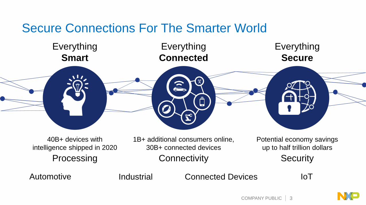
Common NameCombustion
Engine
(ICE)
Mild
Hybrid
(M-HEV)
Full
Hybrid
(F-HEV)
Plug-in
Hybrid
(P-HEV)
Range Extended
EV
(RE-BEV)
Pure Electric
Vehicle
(BEV)
Example
Ford Mustang Honda Insight Toyota Prius FCA Pacifica BMW i.3 Nissan Leaf
Combustion Engine
Battery System
Mains Charging - - -
Electric Traction -
10 – 20 kW 15 – 60 kW 40 – 80 kW 40 – 80 kW > 80 kW
Vehicle Electrification: Diversity of Approaches
LV HV LV HV LV HV LV HV12V 48V12V

COMPANY PUBLIC 9
• Legal – question of responsibility
• Trust – knowing your car will do
what it’s meant to do
• Standardization – platform
consolidation
and system harmonization
• Trends – autonomous driving,
electric vehicles
Why Functional Safety is
Important for the Automotive
Market

COMPANY PUBLIC 10
Domain-BasedArchitecture
Connectivity
Driver Replacement
Powertrain & Vehicle Dynamics
Body & Comfort
In-Vehicle ExperienceSecure
Gate
ways &
Netw
ork
s In-Vehicle
Experience
Gateway
Connectivity
Powertrain &
Vehicle DynamicsDC
DC DC
DC DC
Body & Comfort Driver
Replacement

COMPANY PUBLIC 11
NXP’s next generation power management: Simplicity of safety power
management IC family
Unlimited
combinationsIP Block
Strategy
Safety
FeatureSafety
Feature
Multi-PMIC Solutions for System Power and Safety

COMPANY PUBLIC 12
Body & Comfort
In-Vehicle
Experience
Powertrain &
Vehicle Dynamics
SENSE THINK ACT
Camera
Lidar
Ultrasonic
Cockpit Domain
Controller
SensorFusion
& Planning
PowertrainDomain
Controller
Touch Displays
BodyDomain
Controller
Voice Recognition
Radar
HVAC, Interior Lighting
Doors, seats, steering wheel,
mirrors, wipers, sunroof
Powertrain &
Vehicle Dynamics
eCockpit
Amplifiers
Temp, Light, Humidity
Switch Panels
Motion & Pressure
Speed Engine
Transmission
Brake
Battery Cell Management
Steering
Airbag
Suspension
Connectivity Domain
Controller Cellular
WiFi, BT, GNSS, NFC
V2X
Broadcast Radio
Smart Car Access
Connectivity
Driver
Replacement
Cockpit Domain
Controller
SensorFusion
& Planning
PowertrainDomain
Controller
BodyDomain
Controller
Connectivity Domain
Controller
i.MX 8
S32R2
SAF
TEF
S32
S32V
S32
S32
PROCESSOR PMIC
Next gen VR
Next gen VR
Safety PMIC
FS85
FS84/85
FS66
Safety PMIC
PF8200
Gate
wa
ys &
Netw
ork
s
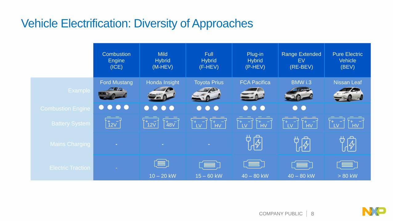
BENEFITS: PMIC DESIGNED & VALIDATED WITH PROCESSOR│COMMON REFERENCE DESIGN │SOFTWARE
One Processor = One Safety PMIC
S32 Safety PMIC
COMPANY PUBLIC 13
FSBC
One Processor = One Safety PMIC
BENEFITS:
• Support MCU’s power and safety scalability platform requirement
• Co-developed and validated with the MCU for an optimized solution
S32 Layerscape
High performance regulators
i.MX
Integrated PMIC
MC33907/8
FS6500,FS8500 PF0100, PF3000
PF8200
VR500
VR5100

COMPANY PUBLIC 14
ISO 26262 @ NXP

COMPANY PUBLIC 15
SET SYSTEM RISK CRITICITY (HAZARD ANALYSIS) ASIL A, B, C or D
DEFINE SAFETY GOALS
IMPLEMENT MEASURES TO REDUCE RISK OF FAILUREDIFFERENT TYPE OF FAILURES
Avoid SYSTEMATIC FAILURESduring development
• Process
• Safety management
• Best practices
• Lessons learned
• Verification & validation
Avoid RANDOM FAILURESduring operation
• System safe state
• Safety architecture
• Quantitative & qualitative analysis
• Documentation
Car OEM
Tier1 &
Silicon
Reduce Risk: Track and Understand Failures
COMPANY PUBLIC 16
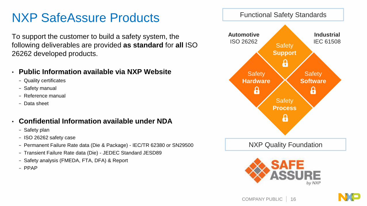
NXP SafeAssure Products
To support the customer to build a safety system, the
following deliverables are provided as standard for all ISO
26262 developed products.
• Public Information available via NXP Website− Quality certificates
− Safety manual
− Reference manual
− Data sheet
• Confidential Information available under NDA− Safety plan
− ISO 26262 safety case
− Permanent Failure Rate data (Die & Package) - IEC/TR 62380 or SN29500
− Transient Failure Rate data (Die) - JEDEC Standard JESD89
− Safety analysis (FMEDA, FTA, DFA) & Report
− PPAP
NXP Quality Foundation
Functional Safety Standards
Safety
Support
Safety
Process
Safety
Hardware
Safety
Software
Automotive
ISO 26262
Industrial
IEC 61508

COMPANY PUBLIC 17
SafeAssure Community Public Space for knowledge
distribution and industry-wide news
here
SafeAssure NDAPrivate NDA space for customer to
access safety documentation
here
SupportSafety Expert Group composed of
Safety Managers and Architects, Field
and Application Engineers
Self SufficientCommunity users find answers to their questions an safety documentation requests
SAFEASSURE COMMUNITIESCustomer Support for Functional SafetySafeAssure Community
Customer support for Functional Safety

COMPANY PUBLIC 18
Power Management
Functional Safety Architecture

COMPANY PUBLIC 19
SET SYSTEM RISK CRITICITY (HAZARD ANALYSIS) ASIL A, B, C or D
DEFINE SAFETY GOALS
IMPLEMENT MEASURES TO REDUCE RISK OF FAILUREDIFFERENT TYPE OF FAILURES
Avoid SYSTEMATIC FAILURESduring development
• Process
• Safety management
• Best practices
• Lessons learned
• Verification & validation
Avoid RANDOM FAILURESduring operation
• System safe state
• Safety architecture
• Quantitative & qualitative analysis
• Documentation
Car OEM
Tier1 &
Silicon
Reduce Risk: Track & Understand Failures

COMPANY PUBLIC 20
ADAS Sensor Battery Management Power Steering
Auto steering, lock, lossFirePhantom detection
ASIL DASIL CASIL B
Examples of a System Dreaded Event and ASIL Levels

COMPANY PUBLIC 21
Safety SBC Integrates MCU Safety MonitoringIndependent Fail Safe State
Machine
• Physical & Electrical
independance to fit for ASILD
• Power Management Monitoring
Unit (UV / OV)
• Analog & Digital Built In Self Test
to minimize Latent Faults
• Own Reference & Supply to
Reduce Common Cause Failure
MCU Monitoring
• FCCU : Fault Collection Control
Unit
• Monitor Dual Core Lock Step
Modes MCUs
HW Redundancy
• Vcore external Monitoring
Safety SBC - FS65
Advanced Watchdog
• Challenger
• Replace external MCU
Monitoring
Fail Safe Pin (FS0b) :
• Redundant System Fail Safe
enabler
• Second Fail Safe pin to assert
safety path with configurable
delay after failure
RSTb – Fail Silent Mode
• Configurable RSTb activation
giving more system availability
Safety MCU
All safety mechanism reaction are < FTTI < 10ms
FTTI = Faul Tolerant Time Interval

COMPANY PUBLIC 22
Fault Management & ASIL Power Supply Quantitative
Analysis
Single Point Fault Latent Fault Common Cause Fault
Input
supply Output
Supply
Power Supply
Voltage
supervisor
Safe state
activation
Input
supply
Output
supply
Power Supply
Voltage
supervisor
Safe state
activation
LF
LBIST & ABIST
Input
supply 1Output
supply
Power Supply
Safe state
activation
LBIST & ABIST
Input
supply 2
BG1
Voltage
supervisor
LF
BG2
ISO 26262 ASIL level ASIL B ASIL D
SPFM
Single Point Failure Metric> 90% > 99%
ISO 26262 ASIL level ASIL B ASIL D
LFM
Latent Point Failure Metric> 60% > 90%
ISO 26262 ASIL level ASIL B ASIL D
PMHF -Probability Metric of
HW Failure< 10E-7 < 10E-8

COMPANY PUBLIC 23
Vpre
From Vsense
External and Internal Analog Paths
SBC
VSENSE
VSUP3
VSUP2
VSUP1
PRE-REGULATOR
Power Management Domain
Monitoring Unit
Internal
Clamp
MainRef. Voltages
Power
Management
Internal
Clamp
FSRef. Voltages
Monitoring Unit
Vpre
RSTb_dig
FS0b_dig
RSTb
FS0b
From Vsense
Power Management Domain
Monitoring Unit
Internal
Clamp
FS
From Vpre or VSUP3
From Vpre or VSUP3
• External and internal analog path
redundancies
• Fail safe output supplied by redundant
and independents analogs paths

COMPANY PUBLIC 24
Digital Architecture Of Monitoring Unit
• Triplication of safety registers with majority voter (e.g. WD period duration)
• Design structure to avoid erratic activation of safety outputs (e.g. FS0b)
• ECC for fuse
• Detection and correction of 1-bit flip (SPI registers of Monitoring Unit)
• Detection of 2-bits flips (SPI registers of Monitoring Unit)
• LBIST to reduce Latent Fault
Several mechanisms are implemented to avoid a bad interpretation of a bit flip (SEU):
COMPANY PUBLIC 25
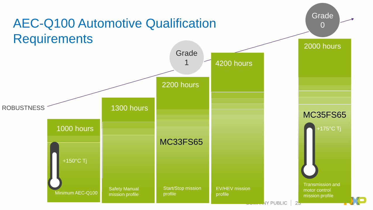
AEC-Q100 Automotive Qualification
Requirements2000 hours
2200 hours
1300 hours
1000 hours
+150°C Tj
+175°C Tj
Transmission and
motor control
mission profile
Start/Stop mission
profileSafety Manual
mission profileMinimum AEC-Q100EV/HEV mission
profile
4200 hours
Grade
0
Grade
1
ROBUSTNESS
MC33FS65
MC35FS65
COMPANY PUBLIC 26
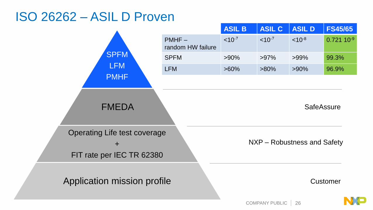
SPFM
LFM
PMHF
FMEDA
Operating Life test coverage
+
FIT rate per IEC TR 62380
Application mission profile
SafeAssure
NXP – Robustness and Safety
Customer
ISO 26262 – ASIL D ProvenASIL B ASIL C ASIL D FS45/65
PMHF –
random HW failure
<10-⁷ <10-⁷ <10-8 0.721 10-9
SPFM >90% >97% >99% 99.3%
LFM >60% >80% >90% 96.9%

COMPANY PUBLIC 27
Safety and Power Management
Solutions: FSBCs

COMPANY PUBLIC 28
Body & Comfort
In-Vehicle
ExperienceConnectivity
Driver
Replacement
Powertrain &
Vehicle Dynamics
Secure Networks & Gateways
NXP Leads Domain Based Vehicle Architectures

COMPANY PUBLIC 29
Sense – Think – ActPower Management & Safety Standards
CAN
FAIL SAFE
Low Power
12V DCDC
0.8A – 1.5A
CAN FD2M
FAIL SILENT
Long Duration
Timer
12V DCDC
+ DCDC 0.8AMC33907/8
FS650x
Secured & Safe System Solutions • ISO26262 architecture (TUV SUD proven)
• Functional robustness (non ISO pulse, EMC, HTOL)
• Security (SM transition)
High Efficient Solutions• Target 12 V & 24 V (application note)
• Dual DCDC architecture (Vpre + Vcore)
• Ultra low power modes (low Iq, long dur. timer)
Safety Simplified Solutions• ISO26262 ready documentation
• System validation test (eFAST)
• Global ecosystem (incl HW & SW)
Gen 1Safety / Chassis
Production
Gen 2Pin to Pin compatible Platform FS45 and FS65
Grade 0 and Grade 1 Qualified, Production
Va
lue
Pro
po
sit
ion
CAN FD2M
FAIL SILENT
Long Duration
Timer
12V DCDC +
LDO 0.5A
FS4500
CAN FD2M
FAIL SILENT
Long Duration
Timer
12V DCDC
+ DCDC 1.5A
FS651x
CAN FD2M
FAIL SILENT
Long Duration
Timer
12V DCDC
+ DCDC 2.2A
FS652x
EXTENDED
FAIL SILENT
Fsynch
12/24V DCDC
+ DCDC 6W
VR55
FS84/85
FS66
Gen 3Scalable platform
12/24V
ASIL B / ASIL D

COMPANY PUBLIC 30
FS65/45 Family – SCALABLE Functional Safety SBC
Solutions
Scala
ble
Po
wer
Man
ag
em
en
t
Scalable System Management
FS45xx1.2V to 5.0V / 500mA
FS650x1.2V to 5.0V / 0.8A
FS651x1.2V to 5.0V / 1.5A
FS652x1.2V / 2.2A
Standard
CAN FD & CANless
e-Safe
CAN FD, FS1b
PowerTrain
CAN FD, LIN, LDT
33FS4500C/N
33FS6500C/N 33FS6501C/N
33FS6511C
33FS6521C
33FS6502C/L
33FS6512C/L
33FS6522L
33FS4501C/N
ADAS HE EMS
Inverter, EMS
BMS, TCUEPS, HEV
Suspension
EPS, BMSMild Hybrid
EPS, HVAC
33FS6503L
33FS6513L
33FS6523L
HE EMS
Gear Box
TCU
PowerTrain
CAN FD, FS1, LDT
35FS6503C/N
35FS6513C/N
Gear Box
TCU >150°C Tj
Grade 0
35FS4501C/N
EV/HEV

COMPANY PUBLIC 31
Quality Management (QM) – VR55 ASIL A/B – FS84 ASIL C/D – FS85
3 W
6 W
10-2
0 W
Infotainment / Clusteri.MX 6/8
Vision, LIDARS32V, others
Sensor FusionS32V, S32x
V2Xi.MX 6/8Radio, Antenna
Mercury, Dirana, i.MX
RADAR : SRR, MRR, LRRS32Rx, others
Power and Safety Scalability
ADAS &
Electrification
Connected Car
Domain Controller - ElectrificationS32S,

COMPANY PUBLIC 32
FS85 – 12/24V and ASIL B/D Scalable ADAS SBCPower Management
• Input supply up to 60V – 12V and 24V systems
• HVBUCK , adjustable 3.3V to 5V, scalable output current up to 10A
• Synchronous Buck, 455kHz or 2.22MHz, ext. MOS
• BUCK1/2, adjustable 0.8V to 1.8V, up to 2.5A DC – 3.6A peak
• Synchronous Buck, up to 3 MHz, int. MOS
• Can operate in multi-phase delivering 5A
• SVS capability on Buck1
• BUCK3, adjustable 1.0V to 3.3V, up to 2.5A DC – 3.6A peak
• Synchronous Buck, up to 3 MHz, int. MOS
• BOOST 5V or 5.74V, up to 800 mA DC- 1.5A peak, int. MOS
• LDO1/2, configurable 1.1V to 5V, up to 400 mA
• Synchronization signal for dual device operation / Power GOOD output
• Frequency Synchronization Fin/Fout.
System Features• Independent Safety Monitoring Unit
• Control via 32 bits SPI and I2C (including CRC).
• Low Power Mode : 10 µA in LPOFF, wake up via WAKE1/2 pins
• AMUX: Battery, Internal Safety critical voltages, Vref and Temperature
• Emulation and Programming capability offered in Engineering mode only :
Voltage, Frequency, Phase shift, Power sequencing.
• EMC: Spread Spectrum, Freq. Synch., Vpre Slew Rate control, Freq. Tuning
Samples : Available
PPAP : Jan 2019

COMPANY PUBLIC 33
Independent Safety
Monitoring Unit
OV/UV
FS85 Architecture Concept
Simplified Integrated Power Supply
Architecture
0.8V
3.3V
PRE-
REGULATOR
Power Management Domain
BATDC / DC
LDO
BOOST
PRE_GHS
PRE_GLS
PRE_SW
PRE_BOOT
PRE_CSPPRE_COMP PRE_FB
VBOOST
BOOST_LS
LDO2
LDO1_IN
LDO1
VSUP1/2
WAKE1
GND/GNDFS
ePAD
BUCK3-IN
BUCK3-SW
FS8530
WakeWAKE2
FIN/Bias
FOUT
FIN
AMUX
VDDIO
VBOS
INTB
BUCK3-INQ
BUCK2-IN
BUCK2-SW
BUCK2-FB
BUCK1-IN
BUCK1-SW
BUCK1-FB
CSB
MOSI
MISO
SPISCLK
Analog
MUX
IN(s)
SDA
VDDI2C
OTP
DBG
BUCK3-FB
RSTB
FS0B
ERRMONExt. IC
Monitoring
MCU Failure
Monitoring
(FCCU)
Voltage
SupervisionVCOREMON
Vdig_FS
VMON1VMON2 Fail Safe
Output Driver
VM
ON
1
VMON3
VM
ON
2
VM
ON
3
VDDIO
Reset
Driver
VM
ON
4
VMON4
PGOOD
DriverPGOOD
LDO1
VPRE
CONTROLLER
ePADBUCK3
BUCK1
BUCK2ePAD
ePAD
I2C
Bias
Control
CLK_MGT
LDO2
Power Management State Machine
VSUP
OSC
MAIN
Vdig
VDDIO
BG1
BG1
TSD
TSD
BG2
BOS
Fail-Safe State Machine
SPIFS
Watchdog
Vdig_FS OTP
OSCFS
ABISTLBIST
FCCU1
FCCU2
ILIM
ILIM
BG1TSD ILIM
BG1TSD ILIM
BG1ILIM
BG1TSD ILIM
BG1TSD ILIM
PSYNC
SCL
Power Management Domain
Monitoring Unit
ELECTRICALLY
AND
PHYSICALLY
INDEPENDENT
FS8530

COMPANY PUBLIC 34
FS85 – 12/24V and ASIL B/D Scalable ADAS SBCVPRE controller:
3.3V – 5V range
10A, 450 kHz or 2.22 MHz
BUCK1, BUCK2:
0.7 – 1.8V range, 2.22 MHz
Ipeak 3.6A, standalone or
multi phase (7.2A peak)
Static Voltage Scaling (SVS)
BUCK3:
1.0 – 3.3V range, 2.22 Hz
Ipeak 3.6A
60V max supply
400mA each
5 or 5.74V,
1.5A peak
3.4 MHz I2C
10 MHz SPI
wake up
Debug and OTP
Analog MUX
Frequency synchronization
in & out
Local 5V supply
INTb & synchronization
Safety Monitoring Unit
BOOST
PRE_GHS
PRE_GLS
PRE_SW
PRE_BOOT
PRE_CSPPRE_COMP PRE_FB
VBOOST
BOOST_LS
LDO2
LDO1_IN
LDO1
VSUP1/2
WAKE1
GND/GNDFS
ePAD
BUCK3-IN
BUCK3-SW
FS8530
WakeWAKE2
FIN/Bias
FOUT
FIN
AMUX
VDDIO
VBOS
INTB
BUCK3-INQ
BUCK2-IN
BUCK2-SW
BUCK2-FB
BUCK1-IN
BUCK1-SW
BUCK1-FB
CSB
MOSI
MISOSPI
SCLK
Analog
MUX
IN(s)
SCL
SDA
OTP
DBG
BUCK3-FB
RSTB
FS0B
ERRMONExt. IC
Monitoring
MCU Failure
Monitoring
(FCCU)
Voltage
SupervisionVCOREMON
Vdig_FS
Vana_FSVMON1VMON2 Fail Safe
Output Driver
VM
ON
1
VMON3
VM
ON
2
VM
ON
3
VDDIO
Reset
Driver
VM
ON
4
VMON4
PGOOD
DriverPGOOD
LDO1
VPRE
CONTROLLER
ePADBUCK3
BUCK1
BUCK2ePAD
ePAD
I2C
Bias
Control
CLK_MGT
LDO2
Power Management
State Machine
VSUP
OSC
MAIN
Vdig
VDDIO
BG1
BG1
TSD
TSD
BG2
BOS
Fail-Safe State Machine
SPI
FSWatchdog
Vdig_FS OTP
OSC
FSABIST
LBIST
FCCU1
FCCU2
ILIM
ILIM
BG1TSD ILIM
BG1TSD ILIM
BG1ILIM
BG1TSD ILIM
BG1TSD ILIM
PSYNC
Power Management
1.1V 1.2V 1.6V
1.8V 2.5V 2.8V
3.3V 5V
COMPANY PUBLIC 35
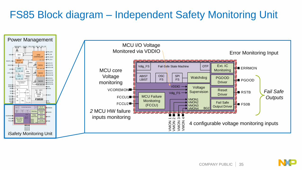
FS85 Block diagram – Independent Safety Monitoring Unit
iSafety Monitoring Unit
BOOST
PRE_GHS
PRE_GLS
PRE_SW
PRE_BOOT
PRE_CSPPRE_COMP PRE_FB
VBOOST
BOOST_LS
LDO2
LDO1_IN
LDO1
VSUP1/2
WAKE1
GND/GNDFS
ePAD
BUCK3-IN
BUCK3-SW
FS8530
WakeWAKE2
FIN/Bias
FOUT
FIN
AMUX
VDDIO
VBOS
INTB
BUCK3-INQ
BUCK2-IN
BUCK2-SW
BUCK2-FB
BUCK1-IN
BUCK1-SW
BUCK1-FB
CSB
MOSI
MISOSPI
SCLK
Analog
MUX
IN(s)
SCL
SDA
OTP
DBG
BUCK3-FB
RSTB
FS0B
ERRMONExt. IC
Monitoring
MCU Failure
Monitoring
(FCCU)
Voltage
SupervisionVCOREMON
Vdig_FS
Vana_FSVMON1VMON2 Fail Safe
Output Driver
VM
ON
1
VMON3
VM
ON
2
VM
ON
3
VDDIO
Reset
Driver
VM
ON
4
VMON4
PGOOD
DriverPGOOD
LDO1
VPRE
CONTROLLER
ePADBUCK3
BUCK1
BUCK2ePAD
ePAD
I2C
Bias
Control
CLK_MGT
LDO2
Power Management
State Machine
VSUP
OSC
MAIN
Vdig
VDDIO
BG1
BG1
TSD
TSD
BG2
BOS
Fail-Safe State Machine
SPI
FSWatchdog
Vdig_FS OTP
OSC
FSABIST
LBIST
FCCU1
FCCU2
ILIM
ILIM
BG1TSD ILIM
BG1TSD ILIM
BG1ILIM
BG1TSD ILIM
BG1TSD ILIM
PSYNC
Power Management
2 MCU HW failure
inputs monitoring
RSTB
FS0B
ERRMONExt. IC
Monitoring
MCU Failure
Monitoring
(FCCU)
Voltage
SupervisionVCOREMON
Vdig_FS
VMON1VMON2 Fail Safe
Output Driver
VM
ON
1
VMON3
VM
ON
2
VM
ON
3
VDDIO
Reset
Driver
VM
ON
4
VMON4
PGOOD
DriverPGOOD
BG2
Fail-Safe State Machine
SPIFS
Watchdog
Vdig_FS OTP
OSCFS
ABISTLBIST
FCCU1
FCCU2
Error Monitoring Input
Fail Safe
Outputs
MCU core
Voltage
monitoring
4 configurable voltage monitoring inputs
MCU I/O Voltage
Monitored via VDDIO

COMPANY PUBLIC 36
Safety Scalability Platform
ITEMS VR55 – QM FS84 – ASIL B FS85 – ASIL C/D
Documentation
& Safety analysis
FTA - - ✓
DFA - - ✓
FMEDA - ✓ ✓
Fault Injection T Report - - ✓
Safety Manual - ✓ ✓
Safety Outputs
PGOOD ✓ ✓ ✓
RSTb ✓ ✓ ✓
FS0b - ✓ ✓
Safety
Functions
Voltage Monitoring 2 4 6
Watchdog No Simple Challenger
External IC Monitoring – single pin No No YES
MCU Monitoring (single and dual pins) - FCCU No No YES
Analog BIST No YES YES
Logical BIST No No YES
MCU Fault Recovery Strategy Compliance No No YES

COMPANY PUBLIC 37
FS84/FS85 – Documentation & Application Support Available✓ Data Sheet
✓ Thermal Tool✓ Including VPRE/VBOOST
ext. components calculation
✓ PCB Schematic
✓ PCB Layout
Recommendations✓ Models - SIMPLIS
✓ Quick Starter
Guide
✓ SafeAssure – FMEDA✓ Safety Manual

COMPANY PUBLIC 38
VR55/FS84/FS85 Scalable Safety & Power PIN TO PIN & SW COMPATIBLE SOLUTIONS
VR55 – Quality Mgt (QM) FS84 – ASIL A/B FS85 – ASIL C/D
Buck1 + Buck2 + Buck3
B1 + B2 (0.7-1.8V / 3.6A peak, int. MOS)
B1 + B3 (1.0-4.1V / 3.6A peak, int. MOS)
B1 (0.7-1.8V / 3.6A peak, int. MOS)
VR5500 FS8430 (multi phase option) FS8530 (multi phase option)
FS8420 (multi phase option) FS8520 (multi phase option)
FS8410 FS8510
FS8400 FS8500
Safety &
Monitoring
Fit for ASIL B (see next table)
SafeAssure
Fit for ASIL D (see next table)
SafeAssure
BOOST (5-5.74V, 1.5A (p), int. MOS) YES YES YES
System Solutions Fsynch, Pgood, AMUX, SPI/I2C,
LPOFF (10µA), Wake Up
Fsynch, Pgood, AMUX, SPI/I2C,
LPOFF (10µA), Wake Up
Fsynch, Pgood, AMUX, SPI/I2C,
LPOFF (10µA), Wake Up
QM
2 x LDO, config, up to 400mA YES YES YES
VPRE (external MOS) 12/24V HV BUCK – 10A 12/24V HV BUCK – 10A 12/24V HV BUCK – 10A

COMPANY PUBLIC 39
Safety Power Management
Domain Solutions – Attach
Strategy

COMPANY PUBLIC 40
Body & Comfort
In-Vehicle
Experience
Powertrain &
Vehicle Dynamics
SENSE THINK ACT
Camera
Lidar
Ultrasonic
Cockpit Domain
Controller
SensorFusion
& Planning
PowertrainDomain
Controller
Touch Displays
BodyDomain
Controller
Voice Recognition
Radar
HVAC, Interior Lighting
Doors, seats, steering wheel,
mirrors, wipers, sunroof
Powertrain &
Vehicle Dynamics
eCockpit
Amplifiers
Temp, Light, Humidity
Switch Panels
Motion & Pressure
Speed Engine
Transmission
Brake
Battery Cell Management
Steering
Airbag
Suspension
Connectivity Domain
Controller Cellular
WiFi, BT, GNSS, NFC
V2X
Broadcast Radio
Smart Car Access
Connectivity
Driver
Replacement
Cockpit Domain
Controller
SensorFusion
& Planning
PowertrainDomain
Controller
BodyDomain
Controller
Connectivity Domain
Controller
i.MX 8
S32R2
SAF
TEF
S32
S32V
S32
S32
PROCESSOR PMIC
Next gen VR
Next gen VR
Safety PMIC
FS85
FS84/85
FS66
Safety PMIC
PF8200
Gate
wa
ys &
Netw
ork
s
BENEFITS: PMIC DESIGNED & VALIDATED WITH PROCESSOR│COMMON REFERENCE DESIGN │SOFTWARE
One Processor = One Safety PMIC
S32 Safety PMIC

COMPANY PUBLIC 41PUBLIC
Driver Replacement
Drive
r
Re
pla
ce
me
nt
Radar
Camera
Lidar
Fusion
SENSE THINK ACT
COMPANY PUBLIC 42
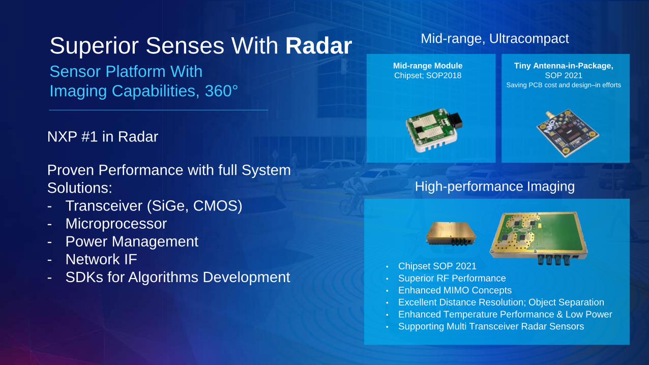
Superior Senses With RadarSensor Platform With
Imaging Capabilities, 360°
Proven Performance with full System
Solutions:
- Transceiver (SiGe, CMOS)
- Microprocessor
- Power Management
- Network IF
- SDKs for Algorithms Development
NXP #1 in Radar
Mid-range, Ultracompact
Mid-range Module
Chipset; SOP2018
Tiny Antenna-in-Package,
SOP 2021Saving PCB cost and design–in efforts
High-performance Imaging
• Chipset SOP 2021
• Superior RF Performance
• Enhanced MIMO Concepts
• Excellent Distance Resolution; Object Separation
• Enhanced Temperature Performance & Low Power
• Supporting Multi Transceiver Radar Sensors

COMPANY PUBLIC 43
FS8400 + S32R + RF RADAR Sensor
VBATNXP - FS8400
VCORE
PGOOD
BUCK1 – 1.25V
VPRE – 4.1V
NXP
MCU
VDDIOLDO1 – 3.3V
FS0B
SPI
AMUX
CLK Mgt (FSYNC)FIN
NXP
RF sensor
MR3003
BOOST – 5.74V
CAN
PHY
LDO2 – 5V
Low Noise
LDO3
3.3V
VCOREmon
VDDIOmon
LDO3mon
LDO2mon
Fail Safe
Sate MachineRSTB
Reset
POR
Safe state activationMCU and/or (PGOOD or RSTB or FS0B)depending on safety concept

COMPANY PUBLIC 44
FS8410 + RF Sensor
Safe state activationMCU and/or (PGOOD or RSTB or FS0B)depending on safety concept
1.1V
1.8V
3.3V
NXP
RF sensor
TEF810X
BUCK3=2.3V
LDO1
VBATNXP - FS8410
VCORE
PGOOD
BUCK1 – 1.25V
NXP
MCU
VDDIOLDO1 – 3.3V
FS0B
SPI
AMUX
CLK Mgt (FSYNC)FIN
CAN
PHYLDO2 – 5V
VCOREmon
VDDIOmon
BUCK3mon
LDO2mon
Fail Safe
Sate MachineRSTB
Reset
POR
BOOST – 5.74V
BUCK3 – 2.3V
VPRE – 4.1V
COMPANY PUBLIC 45
CAMERA Solutions

COMPANY PUBLIC 46
Camera Solutions – ASIL B Based on FS84 + PF82 + S32V2x
FS8430
VPRE
3.3 to 5.3V
60mA gate drive
BUCK2
0.6 to 1.5V, 1.8V
3.6A Peak
BUCK3
1 to 4.1V
3.6A Peak
LDO1
1.8V, 2.5V, 3.3V, 5V
400mA LDO
BOOST
4.5 to 6V
800mA
LDO2
1.8V, 2.5V, 3.3V, 5V
400mA LDO
BUCK1
0.6 to 1.5V, 1.8V
3.6A Peak
PF8200
LPDDR2 /
1.2VDDR
SW1
0.4 to 1.8V
2.5A Buck
0.6V
3.3V
VCORE
1V / 10A
SW2
0.4 to 1.8V
2.5A Buck
SW3
0.4 to 1.8V
2.5A Buck
SW4
0.4 to 1.8V
2.5A Buck
SW5
0.4 to 1.8V
2.5A Buck
SW7
1.2 to 4.5V
2.5A Buck
LDO1
1.5 to 5V
400mA LDO
LDO2
1.5 to 5V
400mA LDO
LDO4
1.5 to 5V
400mA LDO
LDO3
1.5 to 5V
400mA LDO
Available
VBAT
VPRE
Available
VPRE - 5V – 5A
1.8V
GND
HDMI/Ethernet.
1.5V
Available
SW5
SW6
VTT / 0.4 to 1.8V
2.5A Buck
5V / CAN / USB
SAFETY
MONITORING
UNIT
Power Synch.
COMPANY PUBLIC 47
Domain Controller Solutions
COMPANY PUBLIC 48
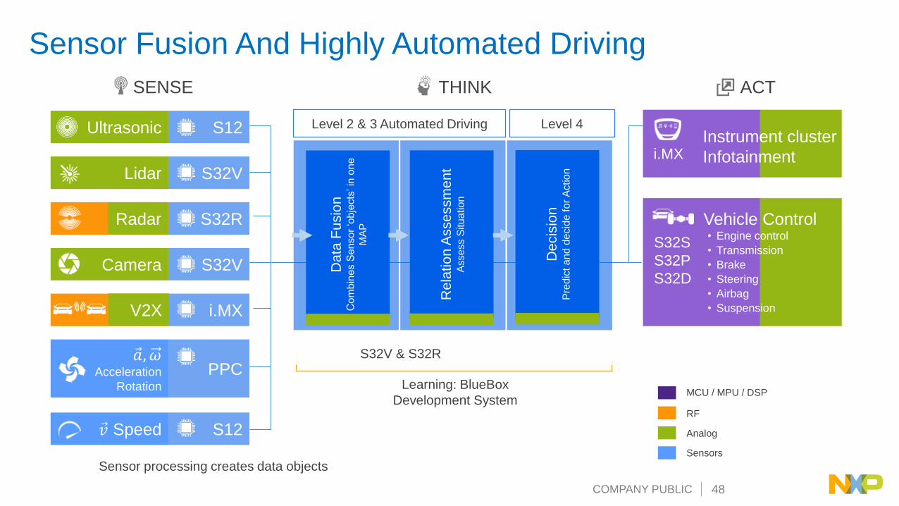
Ultrasonic
Lidar
Radar
Camera
V2X
Ԧ𝑎, 𝜔Acceleration
Rotation
Ԧ𝑣 Speed
S12
S32V
S32R
S32V
i.MX
PPC
S12
SENSE THINK ACT
Level 2 & 3 Automated Driving Level 4
Data
Fu
sio
n
Co
mb
ines S
enso
r ‘o
bje
cts
’ in
on
e
MA
P
Rela
tio
n A
sse
ssm
en
t A
sse
ss S
itu
atio
n
Decis
ion
Pre
dic
t a
nd
de
cid
e f
or
Actio
n
i.MX
MCU / MPU / DSP
RF
Analog
Sensors
Learning: BlueBox
Development System
S32V & S32R
Vehicle Control• Engine control
• Transmission
• Brake
• Steering
• Airbag
• Suspension
Instrument cluster
Infotainment
Sensor processing creates data objects
S32S
S32P
S32D
Radar
V2X
Sensor Fusion And Highly Automated Driving

COMPANY PUBLIC 49
Sensor Fusion Solutions (ASIL D) with FS85 + PF8x
PF8200
LPDDR2 /
1.2VDDR
Buck1
0.8 to 1.8V
2.5A Buck
0.6VREFDDR
1.8V/84mA
VCORE
1V / 10A
Buck2
0.8 to 1.8V
2.5A Buck
Buck3
0.8 to 1.8V
2.5A Buck
Buck4
0.8 to 1.8V
2.5A Buck
Buck5
0.8 to 1.8V
2.5A Buck
Buck6
1.2 to 4.5V
2.5A Buck
LDO1
1.8-2.5-3.3-5V
200mA LDO
LDO2
1.8-2.5-3.3-5V
200mA LDO
LDO4
1.8-2.5-3.3-5V
200mA LDO
LDO3
1.8-2.5-3.3-5V
200mA LDO
Available
FS8530
VPRE
Up to 5.5V
I configurable
SW1
0.7 to 1.8V
3.6A Peak Buck
SW2
0.7 to 1.8V
3.6A Peak Buck
SW3
1 to 4.1V
3.6A Peak Buck
LDO1
1.6-1.8-3.3-5V
400mA LDO
LDO2
1.6-1.8-3.3-5V
400mA LDO
BOOST
5 to 5.74V
1.5A Peak Boost
12VInput
Supply
VPRE
SAFETY
MCU
S32R (ex.)
VPRE - 5V –
5A
3.3V/1.88A
GND
1.5V/4.8mA
*All currents are maximum values
measured with a Vision Algorithm
on the actual S32V234 board
(4x53 cores, M4, APEX, ISP and
Peripherals working).
* Ambient temperature (25°C) for
the 1.2V-1.8V-1.5V-5V-12V rails.
5V/524mA
1.2V / 460mA
Power Synch.
SAFETY
MONITORING
UNIT
COMPANY PUBLIC 50
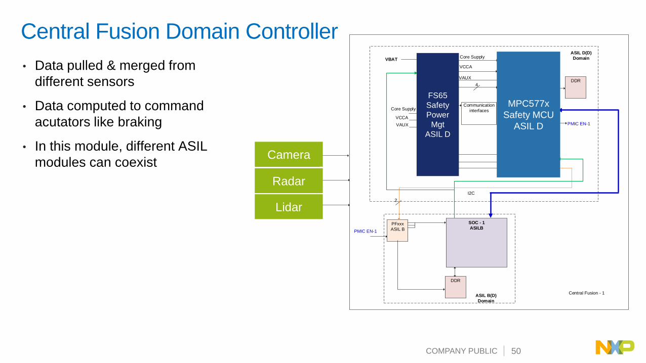
Central Fusion Domain Controller
• Data pulled & merged from
different sensors
• Data computed to command
acutators like braking
• In this module, different ASIL
modules can coexist
SAFETY SBC
FS6500
Safety MCU
ASIL DVBAT
SPI
VCOREMON
VMON1
VMON2
RESETBRSTb
Challenger
WD
MCU HW
Monitoring
FCCU1
FCCU2
PFxxx
ASIL B
SOC - 1
ASILB
I2C
I2C
4
ASIL D(D)
Domain
ASIL B(D)
Domain
DDR
PMIC EN-1
PMIC EN-1
DDR
ERRMON
SOC-1
ERRMON
SOC1
2
FS0b Communication
interfaces
Core Supply
VCCA
Core Supply
VAUX
VCCA
VAUX
CAMERA
RADAR
LIDAR
Central Fusion - 1
FS65
Safety
Power
Mgt
ASIL D
MPC577x
Safety MCU
ASIL D
Radar
Camera
Lidar

COMPANY PUBLIC 51
Safety SBC for ADAS – FS8500 Use Cases
Radar – ASIL B & D Vision – ASIL B Sensor Fusion & HAD – ASIL D
Submarkets
• SRR (Short Range)
• MRR & LRR (Mid & Long Range)
• Radar Fusion (fit for ASIL D)
• Imaging RADAR (fit for ASIL D)
Product Function
• PM + Functional Safety
Attach
• S32Rx (including RRM)
• Sensor
Submarkets
• Camera
• Night Vision
• Lidar
Product Function
• PM + Functional Safety
Attach MCU
• S32V234, (FS + PF)
• Mobileye (eyeQ3, eyeQ4)
Submarkets
• 360° View
• Sensor Fusion
• Autonomous Drive
Product Function
• PM + Functional Safety
Attach MCU
• S32V234, S32S2
• LS (specific architecture)
http://blog.nxp.com/automotive/three-things-to-know-about-functional-safety

PUBLIC
ConnectivityC
on
ne
ctivity V2X
Broadcast Radio
Cellular
WiFi, BT, GNSS,
Smart Car Access
SENSE THINK ACT

COMPANY PUBLIC 53
Infotainment, Radio, V2X Solutions – VR55/FS84 & PF8200 +
i.MX 8
FS84
VPRE
3.3 to 5.3V
60mA gate drive
BUCK1
0.4 to 1.8V
3.6A Peak
BUCK2
0.4 to 1.8V
3.6A Peak
BUCK3
1 to 4.1V
3.6A Peak
LDO1
1.5 to 5V
400mA LDO
LDO2
1.5 to 5V
400mA LDO
BOOST
4.5 to 6V
1A
VBAT SYS_5V
SYS_5V
1V8 / Wifi
5V / CAN / USB
VDD_SNVS_IN
VDD_MAINVDD_MIPI
VDDPLL_MIPIVDD_LVDS
VDD_MEMC
VDD_A72(CPU2)
VDD_DDR_VDDQVDD_DDR_CKEVDD_DDR_PLL
VCC_DRAM
1P8_IOS
1P8_3P3_ IOS (system dependant)
BUCK1(1.0V to 1.15V)
1.0V to 1.15V
SYS_5V
3.0V
BUCK2(1.0V to 1.15V)
VSNVS
BUCK3(1.0V to 1.15V)
BUCK4(1.0V to 1.15V)
BUCK5(1.1V/1.2V/1.35V)
BUCK6(1.1V/1.2V/1.35V)
VDD_GPX1(GPU1)
VDD_GPX2(GPU2)
VDD_A53(CPU1)
VDD_A72
VDD_GPX
IMX8QP
Group 0
Voltage Domain Groups
Group 1 Group 2, 3, 4
BUCK7(1.8V)
3P3_IOS
1P8_3P3_ IOS (system dependant)
VDD_GPX
Miscellaneous Peripherals
1.8/3.3V SDCard1 Supply
VCC_DRAM
SIMCARD / Ethernet
VDD_SCU_1P8
LPDDR Memory
LDO1 (1.8V)
VDD_USDHC1LDO2 (1.8V/3.3V)
HDMI_3P3USB_OTGUSB_3P3
LDO3 (3.3V)
LDO4 (2.5V)
VDD_USDHC2
PF8200
1.1V/1.2V/1.35V
1.8/3.3V SDCard2 Supply
VDD_ENET
VDD_USB_HSIC (opt)
eMMCSupply
VDD_SIM_1P8_3P3
Ethernet
1.0V to 1.15V
1.0V to 1.15V
3V3
3V3 or 1V8
3V3 or 1V8
VDD_A72
VDD_GPX
3V3
PSYNCPGOOD
VSNVS (PF8200)
Start-up:
1) VR55 or FS84 starts: VPRE, BOOST starts
2) PF8200 is starting supplied by VPRE of FS84
3) PGOOD from PF8200 is released when ready
4) VR55 or FS84 detect the PSYNC event and continue
its own power sequence.
SAFETY
MONITORING
UNIT

COMPANY PUBLIC 54PUBLIC
Powertrain &
Vehicle Dynamics
Pow
ert
rain
&
Ve
hic
le
Dyn
am
ics Motion & Pressure
Speed
Ultrasonic
Powertrain &
Vehicle DynamicsEngine
Transmission
Brake
Steering
Airbag
Suspension
Battery Cell Management
Powertrain
Domain
Controller
SENSE THINK ACT

COMPANY PUBLIC 55
New Applications Driving Growth
AC
MM
~
=
ACDC
Charger*
=
=
DCDC**
=
~=
~
Motor control Motor(s)
M
LV
lead-acid
or Li-Ion
Battery
BMS
BMS
DC
12 V
48 V or > 60 V (e.g. 400 V)
* only in (P)HEVs, BEVs, omitted in 48 V MHEV systems
** bidirectional in 48 V systems
*** as in exisiting ICE-based vehicles
HV
Li-Ion
Battery
48 V and HV
Modules
12 V-bus
Modules***
Major components
Motor control
(inverters, HCUs)
DC/DC voltage
domain converter
On-board charger
AC/DC converter
Battery management
system
48 V eMachine
(BSG, ISG, HVAC)

COMPANY PUBLIC 56
Motor control,
inverter, HCU
DC/DC voltage
domain converter
On-board charger
AC/DC converter
Battery management
system
48V eMachine
(BSG, ISG, HVAC)
Mastering xEV Power for Efficient Energy Management
Optimized power system control
with NXP ePowerMaster portfolio
MC
U
SB
C
CO
MM
Drive
r
AF
E
57
75
B
FS
65
TJ
A1
04
x
eS
wit
ch
BC
C7
7x
57
75
E
FS
65
TJ
A1
04
x
GD
31
00
So
ftw
are
res
olv
er
S3
2K
x
FS
45
/ U
JA
11
x
TJ
A1
4x
x
S3
2K
+
TJ
A1
04
x
S3
2K
+
TJ
A1
04
x
COMPANY PUBLIC 57
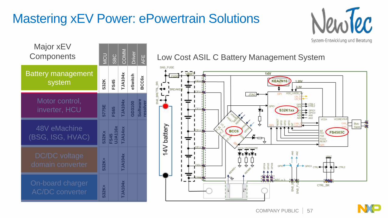
Major xEV
Components
Mastering xEV Power: ePowertrain Solutions
Motor control,
inverter, HCU
DC/DC voltage
domain converter
On-board charger
AC/DC converter
Battery management
system
48V eMachine
(BSG, ISG, HVAC)
MC
U
SB
C
CO
MM
Drive
r
AF
E
S3
2K
FS
45
TJ
A1
04
x
eS
wit
ch
BC
C6
x
57
75
E
FS
65
TJ
A1
04
x
GD
31
00
So
ftw
are
res
olv
er
S3
2K
x
FS
45
UJ
A1
16
x
TJ
A1
4x
x
S3
2K
+
TJ
A1
04
x
S3
2K
+
TJ
A1
04
x
Low Cost ASIL C Battery Management System

COMPANY PUBLIC 58
Major xEV
Components
Mastering xEV Power: ePowertrain Solutions
Motor control,
inverter, HCU
DC/DC voltage
domain converter
On-board charger
AC/DC converter
Battery management
system
48V eMachine
(BSG, ISG, HVAC)
MC
U
SB
C
CO
MM
Drive
r
AF
E
57
75
B
FS
65
TJ
A1
04
x
eS
wit
ch
BC
C7
7x
57
75
E
FS
65
TJ
A1
04
x
GD
31
00
So
ftw
are
res
olv
er
S3
2K
x
FS
45
UJ
A1
16
x
TJ
A1
4x
x
S3
2K
+
TJ
A1
04
x
S3
2K
+
TJ
A1
04
x
Traction Motor Power Inverter Solution
COMPANY PUBLIC 59
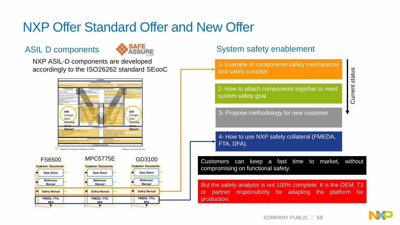
NXP Offer Standard Offer and New Offer
ASIL D components
NXP ASIL-D components are developed
accordingly to the ISO26262 standard SEooC
System safety enablement
Reference ISO 26262-10:2012Applicable to Component developed as SEooC
SW
Compo
nent
Develop
ed as
SEooC
HW
Compo
nent
Develop
ed as
SEooC
NPI LIFECYCLE
TO CES RQ ECQS
CONCEPT DEFINITION PLANNING EXECUTION CLOSURE
PROJECT LIFECYCLE
PDA PPA R PCPCAPI
(4-6/7) Safety
Concept RS & AS
(5-6) Requirements
Specifications (RS)
(5-7) Detailed Design
Specifications (DDTS)
(5-8,9) Initial Safety
Analysis
(5-10) Validation
Testing
(5-7) Block Level
Verification Testing
(8-13) Qualification
Testing
(5-7) Chip Level
Verification Testing
Implement
Safety Documentation Silicon TestingSimulation TestingFunctional Documentation
Diagram Color Schema Development Flow Requirement Traceability
Fault Injection Testing
Fault Injection Testing
Fault Injection Testing
Input Requirements
Standard
Customer
Marketing (MRD)
Internal
Product
Requirements (PRD)
Architectural
Specification (AS)
Data Sheet
Reference
Manual
Safety Manual
FMEDA, FTA,
DFA
(7-5) Production
Testing
Customer Documents
Input Document
PI Gate
Define product type
QM or ISO 26262
R Gate
Product Functional Safety
Assessment Report &
Safety Case
Common to HW and SW
development Model
MPC5775E GD3100FS6500
NPI LIFECYCLE
TO CES RQ ECQS
CONCEPT DEFINITION PLANNING EXECUTION CLOSURE
PROJECT LIFECYCLE
PDA PPA R PCPCAPI
(4-6/7) Safety
Concept RS & AS
(5-6) Requirements
Specifications (RS)
(5-7) Detailed Design
Specifications (DDTS)
(5-8,9) Initial Safety
Analysis
(5-10) Validation
Testing
(5-7) Block Level
Verification Testing
(8-13) Qualification
Testing
(5-7) Chip Level
Verification Testing
Implement
Safety Documentation Silicon TestingSimulation TestingFunctional Documentation
Diagram Color Schema Development Flow Requirement Traceability
Fault Injection Testing
Fault Injection Testing
Fault Injection Testing
Input Requirements
Standard
Customer
Marketing (MRD)
Internal
Product
Requirements (PRD)
Architectural
Specification (AS)
Data Sheet
Reference
Manual
Safety Manual
FMEDA, FTA,
DFA
(7-5) Production
Testing
Customer Documents
Input Document
PI Gate
Define product type
QM or ISO 26262
R Gate
Product Functional Safety
Assessment Report &
Safety Case
Common to HW and SW
development Model
1- Example of components safety mechanisms
and safety concept
2- How to attach components together to meet
system safety goal
3- Propose methodology for new customer
4- How to use NXP safety collateral (FMEDA,
FTA, DFA).
Customers can keep a fast time to market, without
compromising on functional safety.
But the safety analysis is not 100% complete. It is the OEM, T1
or partner responsibility for adapting the platform for
production.
Curr
entsta
tus
COMPANY PUBLIC 60
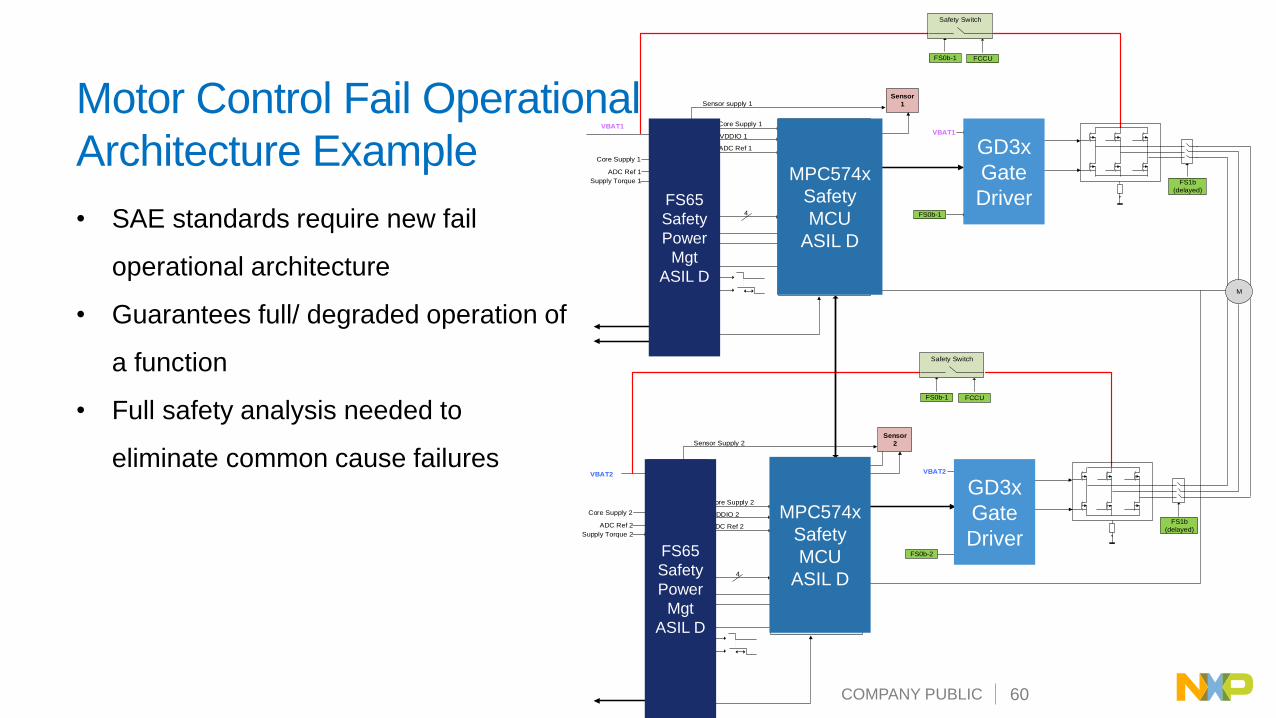
Motor Control Fail Operational
Architecture Example
• SAE standards require new fail
operational architecture
• Guarantees full/ degraded operation of
a function
• Full safety analysis needed to
eliminate common cause failures
FS6500
SAFETY Power
Management
ASIL D Safety MCU - ASIL D
VBAT1 Core Supply 1
VDDIO 1
ADC Ref 1
SPI
VCOREMONCore Supply 1
ADC Ref 1 VMON1
VMON2
RESETBRSTb
Challenger
WD4
FS0b-1
FCCU1
FCCU2
FCCU1
FCCU2
Sensor
1Sensor supply 1
Supply Torque 1
CAN 1
Safety Switch
FS0b-1 FCCU
FS0b-1
Gate driver 1VBAT1
M
FS1b
(delayed)
FS1b
(Delayed)
SAFETY Power
Management
ASIL DSafety MCU - ASIL D
VBAT2
Core Supply 2
VDDIO 2
ADC Ref 2
SPI
VCOREMONCore Supply 2
ADC Ref 2 VMON1
VMON2
RESETBRSTb
Challenger
WD4
FS0b-2
FCCU1
FCCU2
FCCU1
FCCU2
Sensor
2Sensor Supply 2
Supply Torque 2
CAN 2
Safety Switch
FS0b-1 FCCU
FS0b-2
Gate driver 2VBAT2
FS1b
(delayed)
FS1b
(Delayed)
I2C-1
I2C-2
MPC574x
Safety
MCU
ASIL D
MPC574x
Safety
MCU
ASIL D
GD3x
Gate
Driver
GD3x
Gate
Driver
FS65
Safety
Power
Mgt
ASIL D
FS65
Safety
Power
Mgt
ASIL D

COMPANY PUBLIC 61
Battery
Management
System
Internal
Combustion
Engine
Traction
Motor
Integrated
DC/DC
Converter
Hybrid Vehicle
Control Unit
Traction
Motor
Traction
Motor
Traction
Motor
NXP GreenBox
Development Platform
Target Applications

COMPANY PUBLIC 62
Electrification Market Mapping
MCU Performance
DOMAIN
CONTR.
VCU
INVERTER
ABS
ESPEPS
DCDC
12/48
DCDC
12/HVBMS
HV
BMS
48V
BMS
12V
48V EM
12V
48V
HV
BSG
48V
D
D
C
D
C
B
C
D
ASIL Level
C
C
D
OBC
ACDC
C
FS45 FS65
D
Storage Actuation Conversion
MC33904 FS66

COMPANY PUBLIC 63
FS6600 + S32S2 – ASIL D Domain Controller Safety Monitoring
Wake1
VBAT
FS8510
Vcore – 0.8V
Wake2
FCCU s
PGOOD, RSTB
Buck1
(2.5Amps)
VPRE
WAKE
BOOST
LDO2
(400mA)
S32S247Vddio
LDO1
(400mA)
FS0B
SPI
INTB
Fail Safe
Sate Machine
AMUX
To CAN PHY
Buck3
(2.5Amps)
1.8V3.0V
3.3V
5.0V
5.5V
Vcore MON
Vdd 1.8V
Vdd 3.3V
Vdd 5.0 ADC ref
Vdd Core
VM
ON
3
VM
ON
42
2
Vddio
FCCU s
To FS85xx FCCUs inputsVMON1
(Vdd 1.8V)
VMON2
(Vdd 3.3V)Assignment to be done
SPI
INT in
adc in
RST in,
PGOOD in2

COMPANY PUBLIC 64
FS6600 – S32S2 Attach ASIL-D SBCFS85 Derivative for Drive Train Market
Power Management• Input supply up to 60V – 12V and 24V systems
• HVBUCK , adjustable 3.3V to 5V, scalable output current up to 10A
• Synchronous Buck, 300 kHz to 2.5 MHz, ext. MOS
• BUCK1+2, multiphase, adjustable 0.8V to 1.8V, up to 5A DC max
• Synchronous Buck, up to 3 MHz, int. MOS
• BUCK3, adjustable 1.0V to 3.3V, up to 2.5A DC max
• Synchronous Buck, up to 3 MHz, int. MOS
• BOOST 5V to 5.74V, up to 800 mA DC- 1.5A peak, int. MOS
• LDO1/2, configurable 1.1V to 5V, up to 400 mA
• Synchronization signal for dual device operation / Power GOOD output
System Features• Independent Safety Monitoring Unit
• Control via 32 bits SPI (including CRC).
• Low Power Mode : <10 µA in LPOFF, wake up via dedicated pins
• AMUX: Battery, Internal Safety critical voltages, Precise Vref and Temperature
• Emulation and Programming capability offered in Engineering mode only :
Voltage, frequency, phase shift, PW sequencing.
• EMC optimization : Spread Spectrum, Vpre Slew Rate control
Reference silicon available now
FS66 Samples : Now
FS66 PPAP : Q1 2019

COMPANY PUBLIC 65
NXP Safety Backbone Solutions forPowertrain Electrification
Motor control, inverter, HCU
MPC577x+FS65
DC/DC Converter
MPC574x + FS650x
AC/DC converter
MPC574x + FS650x
BMS - Battery Controller
12V S32K1 + FS45
HV MPC577x+FS65
48V eMachine
MPC574x + FS651x
VCU – Domain Control
S32S2x + FS66xMCU Attach Reference
S32S24x FS6600 Green Box
S32K1x FS450x Yes
MPC574x FS650x Yes
MPC577x FS651x Yes

COMPANY PUBLIC 66
Safety Power Management
Conclusion & Perspectives

COMPANY PUBLIC 67
Body & Comfort
In-Vehicle
Experience
Powertrain &
Vehicle Dynamics
SENSE THINK ACT
Camera
Lidar
Ultrasonic
Cockpit Domain
Controller
SensorFusion
& Planning
PowertrainDomain
Controller
Touch Displays
BodyDomain
Controller
Voice Recognition
Radar
HVAC, Interior Lighting
Doors, seats, steering wheel,
mirrors, wipers, sunroof
Powertrain &
Vehicle Dynamics
eCockpit
Amplifiers
Temp, Light, Humidity
Switch Panels
Motion & Pressure
Speed Engine
Transmission
Brake
Battery Cell Management
Steering
Airbag
Suspension
Connectivity Domain
Controller Cellular
WiFi, BT, GNSS, NFC
V2X
Broadcast Radio
Smart Car Access
Connectivity
Driver
Replacement
Cockpit Domain
Controller
SensorFusion
& Planning
PowertrainDomain
Controller
BodyDomain
Controller
Connectivity Domain
Controller
i.MX 8
S32R2
SAF
TEF
S32
S32V
S32
S32
PROCESSOR PMIC
Next gen VR
Next gen VR
Safety PMIC
FS85
FS84/85
FS66
Safety PMIC
PF8200
Gate
wa
ys &
Netw
ork
s
BENEFITS: PMIC DESIGNED & VALIDATED WITH PROCESSOR│COMMON REFERENCE DESIGN │SOFTWARE
One Processor = One Safety PMIC
S32 Safety PMIC
COMPANY PUBLIC 68
During this session you heard
how to:
• Position NXP Power
Management solutions for
Automotive
• Support your design architecture
with scalable Power and Safety
Power Management
• Simplify your ADAS and
Electrification Safety and Attach
MCU Design
COMPANY PUBLIC 69
Summary
• Automotive market requires higher computing, safety and power performance for both the ADAS and Electrification markets
• NXP has a global portfolio of Power Management solutions to support bothmarkets
• Safety and Power Management scalability isunique in terms of:− Core supply power needs
− Voltage input (12V and 24V markets)
− ASIL B and ASIL D
• Next generation MCU + FSBC provide:− Computing, power and safety scalability
− Safety innovations
− Simplified and ready to use ecosystem
COMPANY PUBLIC 70
Join our Community
Public community for NXP power management solutions, it addresses:• Solutions to power i.MX, MPC, S32, LS and LX processors
• Support for Functional safety related items
• EMC considerations in power management
https://community.nxp.com/community/Power-Management?tid=community

COMPANY PUBLIC 71
Other Sessions of Interest
TUESDAY
Session Code Title Presenter CoPresenters Duration Room Start Time
AMF-AUT-T3351Electrification—Functional Safety Backbone
Solutions to Attach with S32David Lopez
Vincent
Lagardelle2 Galilee (Main Floor) 2:30 PM
Session Code Title Presenter CoPresenters Duration Room Start Time
AMF-AUT-T3352Automotive—Safety Power Management Solutions
for Car Electrification and ADASDavid Lopez
Vincent
Lagardelle2 Galilee (Main Floor) 9:00 AM
AMF-AUT-T3402Attach PMIC Offerings for NXP's Next-Generation
Gateway Processors
Vincent
LagardelleDavid Lopez 1 Galilee (Main Floor) 11:00 AM
AMF-AUT-T3349 IGBT Gate Driver for Electric Power Inverters Bruce Bohn 1 Galilee (Main Floor) 1:30 PM
AMF-AUT-T3358 Battery Management Solutions Peter Pinewski 2 Galilee (Main Floor) 2:30 PM
WEDNESDAY

NXP, the NXP logo, and NXP secure connections for a smarter world are trademarks of NXP B.V. All other product or service names are the property of their respective owners. © 2018 NXP B.V.
www.nxp.com