Embed Size (px)
Citation preview

ENGLISH
DEUTSCHITALIAN
OESPAÑ
OL
INSTALLATION GUIDEFRAN
ÇAIS
AXIS Q60 Series
AXIS Q6032-C PTZ Dome Network CameraAXIS Q6034-C PTZ Dome Network CameraAXIS Q6035-C PTZ Dome Network Camera

Legal ConsiderationsVideo and audio surveillance can be prohibited by laws that vary from country to country. Check the laws in your local region before using this product for surveillance purposes. This product includes one (1) H.264 decoder license. To purchase further licenses, contact your reseller.Trademark AcknowledgmentsApple, Boa, Bonjour, Ethernet, Internet Explorer, Linux, Microsoft, Mozilla, Real, SMPTE, QuickTime, UNIX, Windows, Windows Vista and WWW are registered trademarks of the respective holders. Java and all Java-based trademarks and logos are trademarks or registered trademarks of Oracle and/or its affiliates. UPnPTM is a certification mark of the UPnPTM Implementers Corporation.Electromagnetic Compatibility (EMC)This equipment has been designed and tested to fulfill applicable standards for:• Radio frequency emission when installed according to the
instructions and used in its intended environment.• Immunity to electrical and electromagnetic phenomena
when installed according to the instructions and used in its intended environment.
USA - This equipment has been tested using a shielded network cable and found to comply with the limits for a Class A digital device, pursuant to part 15 of the FCC Rules. These limits are designed to provide reasonable protection against harmful interference when the equipment is operated in a commercial environment. This equipment generates, uses, and can radiate radio frequency energy and, if not installed and used in accordance with the instruction manual, may cause harmful interference to radio communications. Operation of this equipment in a residential area is likely to cause harmful interference in which case the user will be required to correct the interference at his own expense.Canada - This Class A digital apparatus complies with Canadian ICES-003.
Europe - This digital equipment fulfills the requirements for RF emission according to the Class A limit of EN 55022. NOTICE! This is a Class A
product. In a domestic environment this product may cause RF interference, in which case the user may be required to take adequate measures. This product fulfills the requirements for emissions and immunity according to EN 50121-4 and IEC 62236-4 railway applications. This product fulfills the requirements for immunity according to EN 61000-6-1 residential, commercial and light-industrial environments. This product fulfills the requirements for immunity according to EN 61000-6-2 industrial environments. This product fulfills the requirements for immunity according to EN 55024 office and commercial environments.Australia - This digital equipment fulfills the requirements for RF emission according to the Class A limit of AS/NZS CISPR 22.
Korea -
Japan - この装置は、クラスA 情報技術装置です。この装置を家庭環境で使用すると電波妨害 を引き起こすことがあります。この場合には使用者が適切な対策を講ずるよう要求され ることがあります。
SafetyThis product complies with IEC/EN/UL 60950-1 and IEC/EN/UL 60950-22, Safety of Information Technology Equipment. The power supply used with this product shall fulfill the requirements for Safety Extra Low Voltage according to IEC/EN/UL 60950-1.In areas where the temperature is above 60 °C (140 °F), the product shall be placed in a restricted access location.Equipment ModificationsThis equipment must be installed and used in strict accordance with the instructions given in the user documentation. This equipment contains no user-serviceable components. Unauthorized equipment changes or modifications will invalidate all applicable regulatory certifications and approvals.LiabilityEvery care has been taken in the preparation of this document. Please inform your local Axis office of any inaccuracies or omissions. Axis Communications AB cannot be held responsible for any technical or typographical errors and reserves the right to make changes to the product and documentation without prior notice. Axis Communications AB makes no warranty of any kind with regard to the material contained within this document, including, but not limited to, the implied warranties of merchantability and fitness for a particular purpose. Axis Communications AB shall not be liable nor responsible for incidental or consequential damages in connection with the furnishing, performance or use of this material. This product is only to be used for its intended purpose.RoHSThis product complies with both the European RoHS directive, 2002/95/EC, and the Chinese RoHS regulations, ACPEIP.WEEE DirectiveThe European Union has enacted a Directive 2002/96/EC on Waste Electrical and Electronic Equipment (WEEE Directive). This directive is applicable in the European Union member states. The WEEE marking on this product (see right) or its documentation indicates that the product must not be disposed of together with household waste. To prevent possible harm to human health and/or the environment, the product must be disposed of in an approved and environmentally safe recycling process. For further information on how to dispose of this product correctly, contact the product supplier, or the local authority responsible for waste disposal in your area. Business users should contact the product supplier for information on how to dispose of this product correctly. This product should not be mixed with other commercial waste.SupportShould you require any technical assistance, please contact your Axis reseller. If your questions cannot be answered immediately, your reseller will forward your queries through the appropriate channels to ensure a rapid response. If you are connected to the Internet, you can:• download user documentation and firmware updates• find answers to resolved problems in the FAQ database.
Search by product, category, or phrases• report problems to Axis support by logging in to your
private support area

ENGLISH
SafeguardsPlease read through this Installation Guide carefully before installing the product. Keep the Installation Guide for further reference.
• When transporting the Axis product, use the original packaging or equivalent to prevent damage to the product.
• Store the Axis product in a dry and ventilated environment.• Avoid exposing the Axis product to vibration, shocks or heavy pressure. Do not install the
product on unstable brackets, unstable or vibrating surfaces or walls, since this could cause damage to the product.
• Only use applicable tools when installing the Axis product; excessive force could cause damage to the product.
• Do not use chemicals, caustic agents, or aerosol cleaners. Use a damp cloth for cleaning.• Use only accessories that comply with technical specification of the product. These can be
provided by Axis or a third party.• Use only spare parts provided by or recommended by Axis.• Do not attempt to repair the product by yourself, contact Axis or your Axis reseller for ser-
vice matters.
• This Axis product shall be used in compliance with local laws and regulations.• The Axis product should be installed by a trained professional. Observe relevant national
and local regulations for the installation.
Battery ReplacementThis Axis product uses a 3.0 V BR2032 lithium battery as the power supply for its internal real-time clock (RTC). Under normal conditions this battery will last for a minimum of 5 years. Low battery power affects the operation of the RTC, causing it to reset at every power-up. A log message will appear when the battery needs replacing. The battery should not be replaced unless required!
If the battery does need replacing, please contact www.axis.com/techsup for assistance.
• Dispose of used batteries according to the manufacturer's instructions.
• Risk of explosion if battery is incorrectly replaced.• Replace only with the same or equivalent battery, as recommended by the manufacturer.

Cleaning of Dome Cover
• Be careful not to scratch or damage the dome cover. Do not clean a dome cover that looks clean to the eye and never polish the surface. Excessive cleaning could damage the surface.
• For general cleaning of a dome cover it is recommended to use a non-abrasive, solvent-free neutral soap or detergent with water and a soft cloth. Rinse well with clean lukewarm water. Dry with a soft cloth to prevent water spotting.
• Never use harsh detergents, gasoline, benzene or acetone etc. and avoid cleaning in direct sunlight or at elevated temperatures.

AXIS Q6032-C/Q6034-C/Q6035-C Installation Guide Page 5
ENGLISH
AXIS Q6032-C/Q6034-C/Q6035-CInstallation Guide
This Installation Guide provides instructions for installing AXIS Q6032-C/Q6034-C/Q6035-C PTZ Dome Network Camera on your network. For all other aspects of using the product, please see the User Manual, available at www.axis.com
Installation Steps1. Check the package contents against the list below.2. Hardware overview. See page 6.3. Install the hardware. See page 13.4. Access the Axis Product. See page 21.
Package ContentsItem Models/variants/notes
Network camera AXIS Q6032-C/Q6034-C/Q6035-C
Media converter switch AXIS T8605
Cable Multi-connector cable (IP66), 5 m (16 ft.)
CD Installation and Management Software CD, including installation tools andother software
Printed materials AXIS Q6032-C/Q6034-C/Q6035-C Installation Guide (this document)Axis Warranty DocumentExtra serial number labels (2x)AVHS Authentication key
Optional accessories Smoked dome coverPower supplyT91A Mounting AccessoriesSee www.axis.com for information on available accessories

Page 6 AXIS Q6032-C/Q6034-C/Q6035-C Installation Guide
Hardware Overview Sunshield
Hole for unit holder (3x)
Screw hole (3x)
Multi-connector
Hook for safety wireAlignment indicator
Unit holder (3x)
Part number (P/N) & Serial number (S/N). The serial number may be required during the installation.
AXIS Q6032-C/Q6034-C/Q6035-C Installation Guide Page 7
ENGLISH
SD card slot
Camera unit
Status LED indicator
Cooling system
Fan
Control button
Dome cover
Rubber gasketMetal ring
Dome ring
Dome ring screw (4x)Dome cover
Metal ringscrew (4x)
Power button(for Factory Default only)
(See page 22 forcleaning instructions.)

Page 8 AXIS Q6032-C/Q6034-C/Q6035-C Installation Guide
Network connector RJ-45 (external)
Network connector SFP
Multi-connector cable
Ground screw
I/O connector
Power connector
Network connector(internal)
Media converter switch
Power connector
Power LED
Network LED indicator (4x)ETH 1/2/3/4 Camera LED
I/O connector
(DC output)
(DC input)
indicator
indicator
(external)
(internal)
(external) (2x)
(2x)

AXIS Q6032-C/Q6034-C/Q6035-C Installation Guide Page 9
ENGLISH
Connectors
CameraSD card slot - A standard or high capacity SD card (not included) can be used for local recording with removable storage.
To insert and remove the SD card, the dome cover must be removed, see Install an SD Card (not included), on page 14.
To prevent corruption of recordings, the SD card should be unmounted before it is ejected. To unmount, go to Setup > System Options > Storage > SD Card and click Unmount.
Multi-connector - Terminal connector for connecting the supplied media converter switch.
The supplied multi-connector cable is required in order to maintain the product’s IP rating.
Media Converter Switch
Network connector RJ-45 (external) - Two RJ-45 connectors (10/100Base-T) for network connectivity.
Power connector (DC input) - 2-pin terminal block for power input.
Function Pin Notes Specifications
DC input GND 1 Ground
12 V DC 2 Power in from power supply (sold separately)
Max load = 7 A12 - 13.2 V DC, min 75 W
Power connector (DC output) - Two 2-pin terminal blocks for power output (pin 4 is not used).
Function Pin Notes Specifications
DC output 12 V DC 1-2 Power out to camera Max load = 6.5 A12 - 13.2 V DC, min 70 W
GND 3 Ground
N/a 4 N/a
- +
21
+ +
21 43
-

Page 10 AXIS Q6032-C/Q6034-C/Q6035-C Installation Guide
Network connector SFP (external) - Two SFP connectors (100Base-FX/1000Base-X) for network connectivity.
Each RJ-45 and SFP connector has its own dip switch. The dip switches control how the port forwards data. See the User Manual for more information.
Network connector (internal) - Two 2-pin Ethernet terminal blocks.
I/O connector (external) - 6-pin configurable I/O terminal block, which is connected to the camera through the multi-connector cable. Use with external devices in combination with, for example, tampering alarms, motion detection, event triggering, time lapse recording and alarm notifications. In addition to ground and power (DC output), the I/O terminal connector provides the interface to:
• Digital output — For connecting external devices such as relays and LEDs. Connected devices can be activated by the VAPIX® Application Programming Interface, output buttons on the Live View page or by an Action Rule. The output will show as active (shown under System Options > Port & Devices > Port Status) if the alarm device is activated.
• Digital input — An alarm input for connecting devices that can toggle between an open and closed circuit, for example: PIRs, door/window contacts, glass break detectors, etc. When a signal is received the state changes and the input becomes active (shown under System Options > Port & Devices > Port Status).
Dip switch position Description of use
Default (middle) B When connecting to the network, directly or through a router or network switch.
Left A When connecting to a camera or a device that is not intended for viewing data.
Right C When connecting to another media converter switch.
Function Pin Notes Specifications
GND 1, 4, 6 Ground
DC output 2 Power out 12 V DC, 50 mA
Configurable I/O 1(Input or Output)
3 Digital input 0 to +30 V DC
Digital output (transistor – open collector)
Max load = 100 mAMax voltage = +30 V DC
Configurable I/O 2(Input or Output)
5 Digital input 0 to +30 V DC
Digital output (transistor – open collector)
Max load = 100 mAMax voltage = +30 V DC
3 65

AXIS Q6032-C/Q6034-C/Q6035-C Installation Guide Page 11
ENGLISH
I/O connector (internal) - 2-pin I/O terminal block.

Page 12 AXIS Q6032-C/Q6034-C/Q6035-C Installation Guide
Multi-Connector CableThe supplied multi-connector cable is required in order to maintain the camera’s IP rating.
Connect the multi-connector cable to the camera’s multi-connector and to the connectors in the supplied media converter switch, see illustrations on page page 6 and page 8. The cable provides the following signals:
•DC power•Network (Ethernet 10/100Base-T)•I/O
Function Pin Wire Notes Specifications
Configurable (Input or Output)
2, 7 Blue, yellow Digital input – Connect to GND to activate, or leave floating (unconnected) to deactivate.
0 to +30 V DC
Digital output – Internal connection to ground when activated, floating (unconnected) when deactivated. If used with an external relay, a diode must be connected in parallel with the load, for protection against voltage transients.
Max load =100 mAMax voltage = +30 V DC
RX+ 3 Green/white Ethernet – receiving
RX- 4 Green Ethernet – receiving
TX+ 5 Orange/white Ethernet – transmitting
TX- 6 Orange Ethernet – transmitting
GND 8 Black Ground
12 V Power 1, 9 Red Used to power camera 12 - 13.2 V DCMax load = 6 A
1 8
2 79
3 6
4 5

AXIS Q6032-C/Q6034-C/Q6035-C Installation Guide Page 13
ENGLISH
Electrical Specifications
Camera LED Indicators
Media Converter Switch LED Indicators
Unit Function Description
Network camera Input Power 65 W (min)
Media converter switch Input Voltage 12.0 - 13.2 V DC
Input Current 6.25 A (min)
Input Power 75 W (min)
Available Output Power 70 W (min)
Nominal Output Voltage 12.5 V DC
Color Indication
Unlit Connection and normal operation.
Amber Steady during startup. Flashes during firmware upgrade.
Amber/red Flashes amber/red if network connection is unavailable or lost.
Red Flashes red for firmware upgrade failure.
Green Shows steady green for 10 seconds for normal operation after restart.
LED Color Indication
Power Unlit DC power unconnected or current protection engaged (power overload).
Green DC power connected.
Network (4x) Amber 10 Mbit connection. Flashes during activity.
Green 100/1000 Mbit connection. Flashes during activity.
Camera Green 100 Mbit connection. Flashes during activity.
75 W
70 W
65 W
Media converter switch
Multi-connector cable
Network camera

Page 14 AXIS Q6032-C/Q6034-C/Q6035-C Installation Guide
Install the Hardware
• This product has a dehumidifying membrane to maintain low humidity levels inside the dome. To avoid condensation, do not disassemble the product in rain or in damp conditions.
• Be careful not to scratch or damage the dome cover. If possible, keep the protective plastic on the dome cover until the installation is complete.
Prepare for InstallationRead all the instructions before preparing to install the network camera since some installation preparation steps may require removing the dome cover and would benefit from being completed together.
• Remove the protective packaging between the camera and the sunshield before installing the camera.
• A smoked dome cover can be purchased from your Axis reseller. Follow the instructions Replace the Clear/Smoked Dome Cover (optional accessory) to replace the dome cover.
• A standard or high capacity SD card (not included) can be used for local recording with removable storage. Follow the instructions Install an SD Card (not included), on page 14, to remove the dome cover and install an SD card.
Replace the Clear/Smoked Dome Cover (optional accessory)A smoked dome cover can be purchased from your Axis reseller.
1. Loosen the dome ring screws and remove the dome ring and dome cover, see illustration on page 6.
2. Remove the metal ring screws, see illustration on page 6.3. Remove the metal ring and dome ring from the plastic dome cover.4. Remove the rubber gasket from the dome cover and attach it to the selected dome cover. Be
sure to attach the gasket so it fits the dome cover perfectly. 5. Align the bulge on the dome cover with one of the logotypes on the dome ring.6. Attach the metal ring and secure by tightening the 4 screws to the maximum stop. 7. If installing an SD card, refer to the instructions Install an SD Card (not included), on page 14.

AXIS Q6032-C/Q6034-C/Q6035-C Installation Guide Page 15
ENGLISH
8. Put the dome ring with the dome cover back in the original position and tighten the screws (torque 4 Nm). Make sure to align the bulge on the dome cover with the cooling system on the camera unit.
Install an SD Card (not included)Installing a standard or high capacity SD card (not included), which can be used for local recording with removable storage, is optional.1. Loosen the dome ring screws and remove the dome ring and dome cover, see illustration on
page 6.2. Insert an SD card (not included) into the SDHC (Secure Digital High Capacity) card slot.3. Put the dome cover back in the original position and tighten the screws (torque 4 Nm). Make
sure to align the bulge on the dome cover with the cooling system on the camera unit, see illustration on page 14.
To prevent corruption of recordings, the SD card should be unmounted before it is ejected. To unmount, go to Setup > System Options > Storage > SD Card and click Unmount.
Cooling system
Dome cover

Page 16 AXIS Q6032-C/Q6034-C/Q6035-C Installation Guide
Install the Power Supply and the Media Converter SwitchThe supplied media converter switch enables the multi-connector cable to send power from the power supply (sold separately) and to send and receive data to and from external alarm devices and the network.
• Make sure the connections to the mains supply and conduits have been installed by a trained professional, according to the manufacturer’s instructions and in compliance with local regulations.
• The power supply (sold separately) and the media converter switch shall be installed in an environment protected against dust and water, for example indoors or in an appropriate cabinet.
• The product shall be connected using a shielded network cable (STP). All cables connecting the product to the switch shall be shielded (STP) and intended for their specific use. Make sure that the switch is properly grounded. See Electromagnetic Compatibility (EMC) for reg-ulatory requirements.
• Axis can only guarantee full functionality with the supplied media converter switch, no other devices are supported.
1. Make sure the mains supply is switched off. 2. Mount the power supply and the media converter switch on the wall or, if applicable, attach
them to a DIN rail in the cabinet. If drilling is required, make sure to use drill bits, screws, and plugs that are appropriate for the material.
3. Loosen the screws and remove the cover from the media converter switch.
Cover
Media converter switch
Screw (2x)
AXIS Q6032-C/Q6034-C/Q6035-C Installation Guide Page 17
ENGLISH
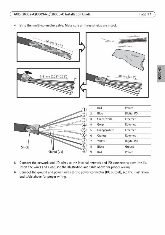
4. Strip the multi-connector cable. Make sure all three shields are intact.
5. Connect the network and I/O wires to the internal network and I/O connectors; open the lid, insert the wires and close, see the illustration and table above for proper wiring.
6. Connect the ground and power wires to the power connector (DC output), see the illustration and table above for proper wiring.
40 mm (1.57”)
7–8 mm (0.28”–0.32”) 30 mm (1.18”)
123456789
1 Red Power
2 Blue Digital I/O
3 Green/white Ethernet
4 Green Ethernet
5 Orange/white Ethernet
6 Orange Ethernet
7 Yellow Digital I/O
8 Black Ground
9 Red Power
Shield Shield (2x)

Page 18 AXIS Q6032-C/Q6034-C/Q6035-C Installation Guide
7. Make sure the clamp is in place and tighten the screws.
• The shield and the clamp surface shall be in full contact with each other so that the multi-connector cable is grounded.
• Make sure all surfaces and contacts are clean and free from scrap shield material.
1
76 5
34
2
89
I/O connector
Ethernet connector
Ethernet connector
Power connector
Shield
Clamp
(DC output)
(internal)
(internal)
(internal)Shield (2x)

AXIS Q6032-C/Q6034-C/Q6035-C Installation Guide Page 19
ENGLISH
8. Connect the network cables to the external network connectors (RJ-45, SFP) as required.
9. If applicable, connect an I/O device to the external I/O connector.10. Connect the power cable (DC input) to the power connector (DC input).11. Attach the ground wire to the ground screw.
Power connector
Network connector
Power cable (DC input)
Network connector
I/O connector
SFP (external) (2x)
RJ-45 (external) (2x)
(DC input)
cableMulti-connector
Ground screw
(external)

Page 20 AXIS Q6032-C/Q6034-C/Q6035-C Installation Guide
12. If connecting several media converter switches in a daisy chain, set the dip switch of each outgoing network connector port that connects to another media converter switch to position C. Leave the dip switch in its default position (position B) when connecting the port directly to the network, see Media Converter Switch, on page 9 and the User Manual for more information.
Always use the default dip switch setting (position B) if the system setup is not defined.
13. Attach the cover to the media converter switch.14. Switch on the mains supply.15. Make sure the LED indicators on the media converter switch indicate the correct conditions. For
information, see Media Converter Switch LED Indicators, on page 12.
Dip switch (4x)
Power LED
Network LED (4x)ETH 1/2/3/4 Camera LED

AXIS Q6032-C/Q6034-C/Q6035-C Installation Guide Page 21
ENGLISH
Install the Network Camera
The supplied multi-connector cable shall be used to comply with the IP66 rated design of the camera.
1. Install the selected bracket (sold separately) according to the instructions supplied with the bracket. If drilling is required, make sure to use drill bits, screws, and plugs that are appropriate for the material. See www.axis.com for information on available mounting accessories.
2. Route the multi-connector cable through the bracket.3. Hook the camera to the safety wire on the bracket.4. Remove the protection cap covering the multi-connector cable connector on the camera.5. Connect the multi-connector cable to the connector on the camera. Use the alignment
indicators to find the correct position.
6. Slide the unit holders on the camera into the slots on the bracket and rotate the camera unit.7. Secure the network camera to the mounting bracket by fastening the 3 screws (Torx T30).
Alignment indicator
Multi-connector cable
Alignment indicator
Safety wire
Screw (x3)
Slot for unit holders (3x)
Mounting example, wall bracket sold separately

Page 22 AXIS Q6032-C/Q6034-C/Q6035-C Installation Guide
Access the Axis ProductUse the software provided on the Installation and Management Software CD to assign an IP address, set the password and access the video stream.
The Live View PageThe product’s Live View page appears in your browser. Click Setup to open the product’s Setup pages, which allow you to customize the Axis product.
Setup - Provides all the tools for con-figuring the product to requirements.
Help - Displays online help on all aspects of using the camera.

AXIS Q6032-C/Q6034-C/Q6035-C Installation Guide Page 23
ENGLISH
Cleaning of Outer Heat SinkDust and particle buildup could affect the performance of the cooling system. To maintain the performance level, the outer heat sink in the camera’s cooling system may need occasional or regular cleaning.
The heat sink may be hot, be careful when touching the heat sink and the heat sink cover.
1. Disconnect the multi-connector cable.2. Loosen the screws (Torx T20) and remove the sunshield.
3. Remove the screws (Torx T30) and lift the heat sink cover.
Do not strain the fan cables or let the heat sink cover hang by the fan cables.
Screw (3x)
Sunshield
1
23
Heat sink cover
Screw (3x)
Fan cables
Heat sink

Page 24 AXIS Q6032-C/Q6034-C/Q6035-C Installation Guide
4. Remove dust and specks of dirt by blowing on the heat sink, for example by using a small air compressor or a can of compressed air. The heat sink may also be rinsed with clean water.
5. Put the heat sink cover back in its original position and tighten the screws (torque 2.4 ±0.2 Nm).
6. Put the sunshield back in its original position and tighten the screws (torque 1.2 ±0.1 Nm).7. Connect the multi-connector cable to the connector on the camera.
Resetting to the Factory Default SettingsTo reset the camera to the original factory default settings, use the Control button and the Power button on the side of the camera. This will reset all parameters, including the IP address, to the Factory Default settings:
1. Remove the dome ring and dome cover, this will automatically disconnect power from thecamera.
2. Press and hold the Control button and the Power button at the same time.3. Continue to hold down the Control button and the Power button until the Status indicator
flashes amber (this may take up to 15 seconds).4. Release the Control button. When the Status indicator changes to green (which may take up to
1 minute) the process is complete and the camera has been reset. The unit now has the default IP address 192.168.0.90Note: The Status indicator will display green for 10 seconds only. After that it will be unlit. Refer to the Status indicator table on page 12 for more information.
5. Release the Power button.6. Replace the dome ring and dome cover; this will automatically reconnect power to the camera.7. Re-assign the IP address, using one of the methods described on the Installation and
Management Software CD.It is also possible to reset parameters to the original factory default settings via the web interface. For more information, see the online help or the User Manual available at www.axis.com
Further InformationThe User Manual is available from the Axis Web site at www.axis.com
Tip! Visit www.axis.com/techsup to check if there is updated firmware available for your network camera. To see the currently installed firmware version, see Setup > About.
Learn more! Visit Axis learning center www.axis.com/academy for useful trainings, webinars, tutorials and guides.


Installation Guide Ver.1.3
AXIS Q6032-C/Q6034-C/Q6035-C Printed: October 2012
© Axis Communications AB, 2012 Part No. 48913