Embed Size (px)
Citation preview

BARCOL-AIR Radiant Gypsum Ceiling System (BRG)Radiant for Cooling or Heating

Page 2 of 14 03/02/2013Barcol-Air Radiant Gypsum BRG EN-Imperial
Barcol-Air Ltd115 Hurley RoadOxford, CT 06478P. 203-262-9900
Table of Contents Page
Table of Contents 2
General Description 3
Piping in the Ceiling Cavity 3
Ceiling Finish 4
Installation 5
Determining the Surface Specifi c Heating or Cooling Capacity 6-8
Determining Pressure Loss Through a 12 mm Copper pipe 9
Hydraulics 10
Acoustics 11
Commisioning 12
Pictures/ References 13
Barcol-Air Ltd. continuously strives to optimize the construction and the quality of all products. Barcol-Air Ltd. therefore, reserves the right to undertake modifi cations in product specifi cations without notice or obligation.
©Copyright Barcol-Air Ltd. 2013
No part of this publication may be multiplied and/or made public by means of print, photocopy, microfi lm or in any other manner without the prior written authorization of Barcol-Air Ltd.

Page 3 of 1403/02/2013 Barcol-Air Radiant Gypsum BRG EN-Imperial
Barcol-Air Ltd115 Hurley RoadOxford, CT 06478P. 203-262-9900
General DescriptionThere is no visible difference between the BRG Chilled Ceil-ing and an ordinary plaster ceiling. It is distinguished not only by its ingenious technical functionality but also by its high aesthetic quality. The plaster underside produces a seamless ceiling The BRG is used in offi ce buildings, government buildings, deparment stores, shopping centers and in R&D laborato-ries. It is used wherever a high standard of fi nish is required,demanding a combination of aesthetics and high prefor-mance. It is particularly outstanding when used in quiet rooms, as thermal expansion of the coils does not create any noise.
• Flexible design for architectures; i.e. unique possibilities with a seamless ceiling fi nish• Energy-effi cient cooling• Draft-free cooling, in accordance with DIN, ISO, SIA and EN standards• May be used for heating• Low cost of product• Minimal maintenance outlay• Highest Possible Human ComfortSM• 100% reproducible output• Low water resistance• Installation without a permanent connection between the heat conductors and panels or substructure, preventing any cracks in the fi lled seams between the panels. In addition, no noise occurs in the ceiling, as there are no permanent (hydraulic) connections.• Calibrated copper pipes (diameter = 12 mm)• Effi cient and quick installation• Cooling or heating effect with a high heat transfer
Piping in The Ceiling CavityInstallation of the coil is particularly advantageous, as it is in-stalled absolutely independently of the ceiling. Additionally, to maintain the independence of the panels, the Barcol-Air Ltd. coils are connected to the cold water piping via fl exible hoses. The connection can also be made by soldered or threaded connection to the copper pipe. Barcol-Air Ltd. has carried out a long series of experiments to create a permanently-sealed, maintenance-free connection between the coil and the hose connectors, in order to provide the best possible solution for its customers. Barcol-Air also pays very close attention to the quality of material and workmanship when selecting its hose suppliers. The hose material used is precisely matched to the high demands, thus providing a reliable connection, even in inaccessible ceiling cavities.
3.1 3.2
Plaster ceiling
Plasterboard
0/5
mm
5/0
mm

Page 4 of 14 03/02/2013Barcol-Air Radiant Gypsum BRG EN-Imperial
Barcol-Air Ltd115 Hurley RoadOxford, CT 06478P. 203-262-9900
Ceiling FinishSelection of the panels depends on the cooling capacity to be achieved and the architectural design. The panels may be in the form of fi ber-reinforced plas-terboard, plasterboard, thermo board or metal honeycomb panels. Perforated surfaces in other patterns are also pos-sible. Panel lengths may be up to about eight feet, and the width up to four feet, depending on the type of surface and the manufacturer selected.As there are no restrictions to any indi-vidual surface fi nish, different techniques may be used, e.g. plaster stopping, sim-ple rolling or even thin plaster. However, a thick layer of plaster means a reduction in cooling capacity is expected. It is not necessary to activate the entire surface of the ceiling in most cases, resulting in a combination of thermally active and in-ert ceiling surfaces. It is, of course, also possible to combine seamless ceiling sur-faces (e.g. plasterboard) with other ceil-ing systems (e.g. metal acoustic panels). The plaster ceiling can also be integrated into the space as a single sail.
Free Design of Ceiling SurfaceThe division of the ceiling into an active cooling surface and an inert surface, is a function of the cooling capacity require-ments. The surfaces must be divided so that installation of lighting or loudspeak-ers may be implemented properly. There is also a variety of methods of joining seamless ceiling surfaces to the wall. Alternatives, such as projecting edges and indirect lighting cavities are available alongside common wall connections such as ames tape or open shadow gaps. Re-movable panels may be used for access to the ceiling cavity.
4.2
4.1
4.3

Page 5 of 1403/02/2013 Barcol-Air Radiant Gypsum BRG EN-Imperial
Barcol-Air Ltd115 Hurley RoadOxford, CT 06478P. 203-262-9900
InstallationThe C mounting sections, rigid under compression, are suspended from the bare ceiling lengthwise on nonius hangers, in accordance with DIN 18168, the standard for ceiling paneling.The Barcol-Air Ltd. heat conductors are inserted between the C-sections of the substructure, using specially developed supports. It is essential that no rigid connection be made between the C-sections and the coils. The heat conductors are made of high-quality extruded aluminum section. The section itself consists principally of a circular duct open at the top and a precision fl at heat diffusion board. The surfaces are in unfi nished or black aluminum.
High surface contact is achieved between the aluminum heat conductors and the calibrated precision copper pipe in a special rolling process. The standard diameter is 12 mm. The high precision of the C-section of the heat conductor and the copper pipe and the optimized, pre-stressing of the C-section fl anks facilitate optimal contact between the pipe and heat conductor, thus minimiz-ing any heat transfer loss
At this stage, a surface is formed by seamless panels (plasterboard, plaster thermo board or metal honeycomb panels). The range of alternatives is al-most infi nite. The panels are joined to the C-mounting sections of the ceiling substructure. It is essential that they only be attached to the mounting sec-tions, to prevent noise and cracking in the fi lled seams of the panels. When the ceiling is complete, the seams are fi lled and the visible side of the ceiling sanded ready for painting.
Perforated panels with acoustic fl eece and rock wool matting on the reverse may also be used to improve acoustic absorption in the room. A variety of perforation patterns is available, of course, to suit the developer‘s wishes. The entire thickness of a seamless BRG chilled ceiling is between 3 1/8” and 4”, from the lower surface of the fi nished ceiling to the upper surface of the substructure or cooling coil.
5.1
5.2
5.3
5.4 5.5
Recommendations for InstallationThe BRG plaster chilled ceiling is designed to integrate installations such as, lighting, sensors, wall connections, aprons, loud-speaker and multimedia projectors, venti-lation outlets, sprinkler systems, stepped ceilings etc. These installation and other details are typically known to use conven-tional dry, mortar-free construction, which can all be fully integrated into the BRG chilled ceiling. See fi gures 5.4 and 5.5 for examples.

Page 6 of 14 03/02/2013Barcol-Air Radiant Gypsum BRG EN-Imperial
Barcol-Air Ltd115 Hurley RoadOxford, CT 06478P. 203-262-9900
Determining the Surface-Specifi c Heating and Cooling Capacity
Determining the Active AreaFig. 6 shows the gypsum area in red and the active area in blue:As the active are is smaller than the gypsum ceiling area, the active area must be used to determine the total cooling capacey of any given ceiling area.
Fig. 6

Page 7 of 1403/02/2013 Barcol-Air Radiant Gypsum BRG EN-Imperial
Barcol-Air Ltd115 Hurley RoadOxford, CT 06478P. 203-262-9900
Standart CoolingFig. 7 shows the spatial curve, determined by analogy with DIN 4715-1, as a function of the mean differ-ence in temperature. Standard cooling capacity relates to applications under the following conditions:
• 9 feet ceiling height• Active area• No ventilation in the ceiling area• Symmetrical arrangement of the sources of heat in the room• No allowance for mass storage potential• 3/8” thermo board or 1/2” standard board• Mineral wool acoustic lining• Substructure spacing of 16 1/2” is used for panels with no perforation and 12 1/2” for perforated pan-els.
0
5
10
15
20
25
30
35
40
45
0 2 4 6 8 10 12 14 16 18 20 22 24 26
BTU/
sqft
activ
ated
HCR
sur
face
Mean temperature difference T
Knauf Thermal Panel with 4.21" HCR width
Sandard Gypsum 0.49" Panel with 4.21" HCR width
The mean temperature difference (Δtm ºF) for cooling is calculated as follows:Δtm (ºF) = Room Temp. (ºF) - [(Supply Water Temp. (ºF) + Return Water Temp. (ºF))/2]
Fig. 7

Page 8 of 14 03/02/2013Barcol-Air Radiant Gypsum BRG EN-Imperial
Barcol-Air Ltd115 Hurley RoadOxford, CT 06478P. 203-262-9900
Standard HeatingFig. 8 shows the spatial curve, determined by analogy with DIN 4715-1, as a function of the mean difference in temperature. Standard heating capacity relates to applications under the following conditions:
• 9 feet ceiling height• Active area• No ventilation in the ceiling area• No allowance for mass storage potential• 3/8” thermo board or 1/2” standard board• Mineral wool acoustic lining• Substructure spacing of 16 1/2” is used for unperforated panels and 12 1/2” for perforated panels.
0102030405060708090
100
0 5 10 15 20 25 30 35 40 45 50 55 60 65 70 75 80
BTU
/sqf
t act
ivat
ed H
CR
sur
face
Mean temperature difference T
Knauf Thermal Panel with 4.21" HCR width
Sandard Gypsum 0.49" Panel with 4.21" HCR width
The mean temperature difference (Δtm ºF) for heating is calculated as follows:Δtm (ºF) = [(Supply Water Temp. (ºF) + Return Water Temp. (ºF))/2] - Room Tempe. (ºF)
Fig. 8

Page 9 of 1403/02/2013 Barcol-Air Radiant Gypsum BRG EN-Imperial
Barcol-Air Ltd115 Hurley RoadOxford, CT 06478P. 203-262-9900
Fig. 9
0.00
0.01
0.02
0.03
0.04
0.05
0.06
0.07
0.08
0.09
0.10
0.11
0.12
0.13
0.14
0.15
0.16
0.17
0.18
0.19
0.20
0.21
0.22
0.23
0.24
0.25
0.26
0.27
0.28
0.29
0.30
20 30 40 50 60 70 80
Res
ista
nce
of
On
e H
eat
Co
nd
uct
ing
Rai
l(p
si)
Length of Heat Conducting Rail (in)
22
24
27
30
32
35
37
40
43
45
48
51
53
56
59
61
64
67
69
72
74
77
80
Water Quantity(gal/hr)
Determining Pressure Loss Through 12mm Copper Tube
The excellent heat conduction from the sur-face of the active panels to the chilled water of the BRG system is based on a high inter-nal heat conduction coecient applicable to turbulent fl ow.The diagram in Fig 9 shows the resistance of one heat conducting rail with a copper tube of 12 mm diameter as a function of the circuit water volume and the length of the heat conducting rail. In order to determine the total circuit resistance, the value derived from the diagram must be multiplied by the number of panels and heat conducting rails (HCR) connected in series and added to the resistance of all fl exible hoses in the circuit.
Miminum Flow RateIn order to obtain turbulent fl ow condi-tions the water quantity of the circuit should not be below 18.49 gal/h for the12 mm tube. This can be achieved by connecting the necessary number of panels in series. In situations where turbulent fl ow can not be achieved, the specic cooling capacity must be correct-ed accordingly.
ΔpTOT = (Δp1*nP*nHCR)+ ΣΔpcΔptot = total resistance of the circuitΔp1 = resistance of one heat conducting rail according to diagram 9np = number of panels in seriesnHCR = number of heat conducting rails on each panelΣΔpc = residance of fl exible connectors, as indicated in the section ‘Hydraulic”
Page 10 of 14 03/02/2013Barcol-Air Radiant Gypsum BRG EN-Imperial
Barcol-Air Ltd115 Hurley RoadOxford, CT 06478P. 203-262-9900
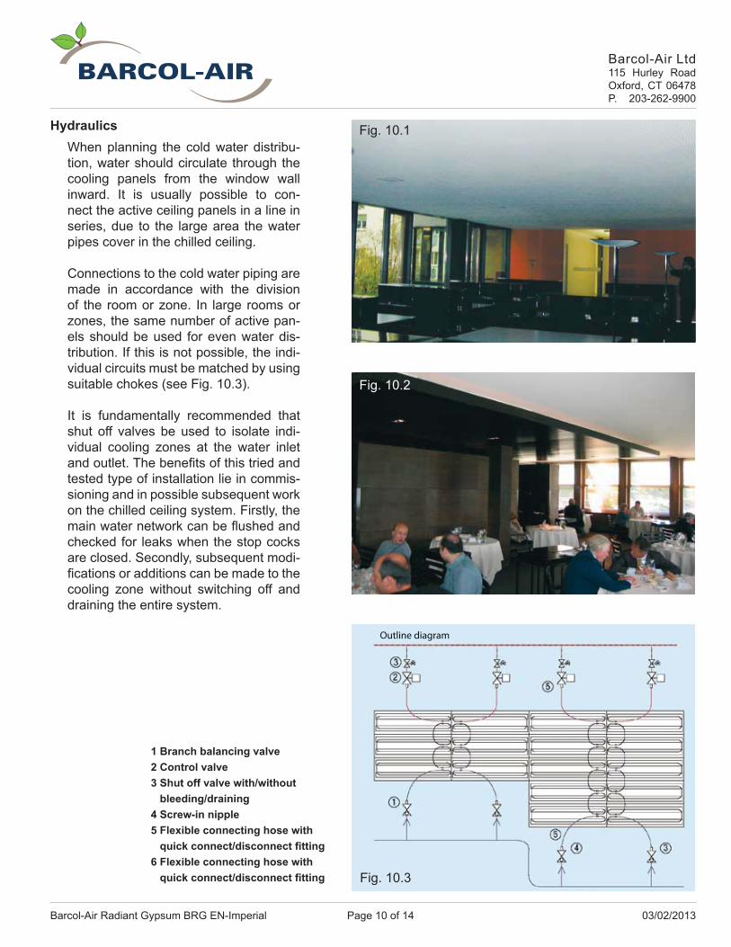
Outline diagram
HydraulicsWhen planning the cold water distribu-tion, water should circulate through the cooling panels from the window wall inward. It is usually possible to con-nect the active ceiling panels in a line in series, due to the large area the water pipes cover in the chilled ceiling.
Connections to the cold water piping are made in accordance with the division of the room or zone. In large rooms or zones, the same number of active pan-els should be used for even water dis-tribution. If this is not possible, the indi-vidual circuits must be matched by using suitable chokes (see Fig. 10.3).
It is fundamentally recommended that shut off valves be used to isolate indi-vidual cooling zones at the water inlet and outlet. The benefi ts of this tried and tested type of installation lie in commis-sioning and in possible subsequent work on the chilled ceiling system. Firstly, the main water network can be fl ushed and checked for leaks when the stop cocks are closed. Secondly, subsequent modi-fi cations or additions can be made to the cooling zone without switching off and draining the entire system.
Fig. 10.1
Fig. 10.2
Fig. 10.3
1 Branch balancing valve2 Control valve3 Shut off valve with/without bleeding/draining4 Screw-in nipple5 Flexible connecting hose with quick connect/disconnect fi tting6 Flexible connecting hose with quick connect/disconnect fi tting

Page 11 of 1403/02/2013 Barcol-Air Radiant Gypsum BRG EN-Imperial
Barcol-Air Ltd115 Hurley RoadOxford, CT 06478P. 203-262-9900
Fig. 11
AcousticsIn working systems, the reverberation time is adapted to the respective requirements by specifi c absorbent lining of the surfaces surrounding the room. The suspended ceiling is a very important surface for this pur-pose. The deductible absorbent ceiling surface area is the surface area of perforated plasterboard lined with fl eece ex works.
The graph in Fig 11 below shows the degree of acoustic absorption in a standard ceiling board as a function of frequency, under the following conditions:
• Standard plasterboard, 1/2” (12 mm) thick• Perforation patterns 15/30 R, 8/18 R, 8/15/20 R• With acoustic fl eece, without rock wool
The principal factors infl uencing acoustic absorption are:
• The ceiling board material and the choice of acoustically-effective perforation• The physical properties of the insulating material• The design of the ceiling (geometry)
0
0.1
0.2
0.3
0.4
0.5
0.6
0.7
0.8
0.9
1
3015 30
15 1575
9 18 18
5 8 10
100
125
160
200
250
315
400
500
630
800
1000
1250
1600
2000
2500
3150
4000
5000
Straight round perforation 15/30 R
Straight round perforation 8/18 R
PLUS scattered perforation 8/15/20 R
Straight round perforation 15/30 R
Straight round perforation 8/18 R
PLUS scattered perforation 8/15/20 R
Deg
ree
of a
cous
tic a
bsor
ptio
n [-]
Frequency [Hz]
Page 12 of 14 03/02/2013Barcol-Air Radiant Gypsum BRG EN-Imperial
Barcol-Air Ltd115 Hurley RoadOxford, CT 06478P. 203-262-9900
Commisioning Pressure TestThe chilled ceiling system must be checked for leaks before commissioning, like any hydraulic system. The completely fi lled and bled chilled ceiling system, including capillary tubing, the plaster coils and the fl exible hose connections must be subjected to a pressure test for at least 24 hours. The result must be recorded in a pressure certifi cate. The ceiling is then released for paneling. Local regulations and requirements must be followed.
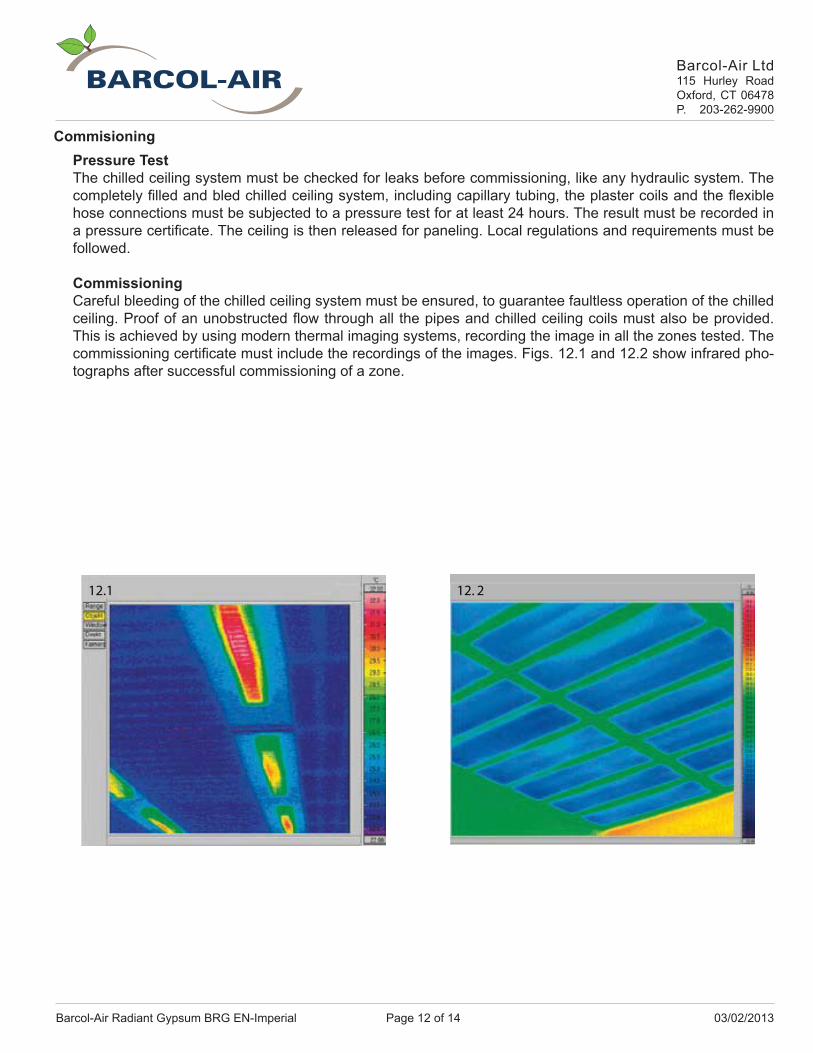
CommissioningCareful bleeding of the chilled ceiling system must be ensured, to guarantee faultless operation of the chilled ceiling. Proof of an unobstructed fl ow through all the pipes and chilled ceiling coils must also be provided. This is achieved by using modern thermal imaging systems, recording the image in all the zones tested. The commissioning certifi cate must include the recordings of the images. Figs. 12.1 and 12.2 show infrared pho-tographs after successful commissioning of a zone.
12.1 12. 2
Page 13 of 1403/02/2013 Barcol-Air Radiant Gypsum BRG EN-Imperial
Barcol-Air Ltd115 Hurley RoadOxford, CT 06478P. 203-262-9900
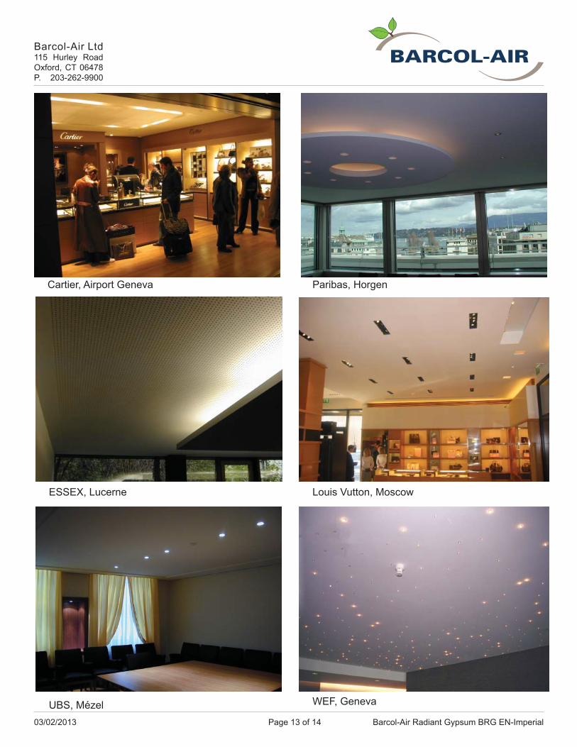
Cartier, Airport Geneva Paribas, Horgen
ESSEX, Lucerne Louis Vutton, Moscow
UBS, Mézel WEF, Geneva

Contacts
Headquarters
Barcol-Air Ltd.115 Hurley RoadOxford, CT 06478Phone: (203) 262-9900Fax: (203) 262-9906Email: [email protected]: www.barcolairusa.com
West Coast Offi ce
Barcol-Air Ltd.Georgetown Center, Building B5963 Coreson Avenue SouthSeattle, WA 98108
Email: [email protected]: www.barcolairusa.com
Your partner for radiant cooling and heating,chilled beams and VAV systems.