Embed Size (px)
Citation preview

1
BELT CONVEYORS II
Mechanical Engineering Department
Carlos III University
BELT CONVEYORS
TRANSPORTATION
BELT CONVEYORS II
INTRODUCTION
A belt conveyor is rubber or textile structure with a belt shape closed ring, with a vulcanized or metallic joint, used for material transportation.
• Belt conveyors are the mostused for transport of solidobjects and bulk materials at great speed, covering greatdistances (up to 30 km)

2
BELT CONVEYORS II
COMPONENTS
Drivingpulley Belt
Unloading Carryingidlers
Return idlers
Tailpulley
Take up weight
Structuralsupport
Snubpulley
Scraper
Bin or hopper
Work run
Free/return run
BELT CONVEYORS II
BELT
Textile belts or smooth textiles
•Definition (UNE 18 025):
–The width, expressed in mm.
–The quality of the cover (standard UNE 18 052).
–The number of plies.
–The quality of the fabric (standard UNE 18 052).
–The thickness of the top cover (tenths of mm).
–The thickness of the bottom cover (tenths of mm).
–The length of the belt (metres).
500 / A – 4 L / 35 – 15 des 50 UNE 18025Width of the belt (mm)
Highly resistant to abrasion
Consists of 4 light plies (L type)
Thickness of the top cover (tenth mm)
Thickness of the bottom cover (tenth mm)
Length (m)

3
BELT CONVEYORS II
BELT
Textile belts or smooth textiles
•Quality of the covers (UNE 18 052)
•Quality of the fabric (UNE 18 052)
3501050C
5002000B
5502500A
Elongation at rupture (%)Tensile strength
(g/mm2)Quality of the cover
352075P
302070LS
252060L
Elongation at rupture
(%)
Tensile strength
(kgf/cm)
Weft
Tensile strength (kgf/cm)
WarpQuality of the
fabric
BELT CONVEYORS II
BELT
Textile belts or smooth textiles
• Number of plies:
1100
mS Tz
B R
⋅=⋅ ⋅
Safety factor
131211Safety factor (S)
More than 9from 6 to 9from 3to 5Number of plies (z)
Safety Factors for textile Carcass Belts (DIN 22101 standard)
Belt width
(metres)
Maximum stress
work of the belt (kgf )
Nominal tensile
strength of each
textile ply (kgf/m)
• It depends on the time the belt
finishes its travel, which depends on:
– The number of flexures on the
pulleys.– The load impacts.
• If time travel is above 5 minutes⇒⇒⇒⇒ - 2
plies

4
BELT CONVEYORS II
BELT
Belt conveyors for vertical or inclined transport
• Drawback of smooth textile belt:
– Grade limit : 18º - 20º
• Different solutions:
– Profile belts:
• Herringbone profile.
• Nasta, Nappula, Ripa and Pyramid profile.
• Grip Top profile.
• Ripro profile.
– U-cleats and V-cleats profiles.
– Corrugated edge belt.
BELT CONVEYORS II
PULLEYS
Bigger angle Bigger force transmitted
Driving pulley
Entrusted of transmiting movement by means of the motor-speed reducer.
• Guarantee maximum adherence ⇒⇒⇒⇒ Low slip.
Simple pulley
ϕ = 180ºSimple plulley with snub
pulley
210º ≤ ϕ ≤ 230º
Tandem motor
350º ≤ ϕ ≤ 480º

5
BELT CONVEYORS II
TENSION
• The tension varies along the belt length.
• Depends on:
– Belt conveyor arrangement.
– The number and arrangement of the drive pulleys.
– The drive and brake features.
– The type and tension devices arrangement.
– Operation phase (start-up, normal operation, braking, etc.).
BELT CONVEYORS II
TENSION
One drive pulley
•Most common situation.
• Operation conditions:
– Peripheral forces applied to the drive pulley have to be transmitted to the
belt by friction without slippage.
– The applied tension to the belt has to be adequate to avoid an important sag
(between two pulleys).
Roll angle

6
BELT CONVEYORS II
TENSION
One drive pulley
• Euler-Eytelwein (without slip) equation:
1
2
Te
T
µ ϕ⋅=
1 2 uT T F= +
1 2
2
1T T
eT
µ ϕ⋅− = − 1 2
2 2
1uFT Te
T T
µ ϕ⋅− = = −
2 1
1
( 1)u T uT F C F
eµ ϕ⋅= ⋅ = ⋅−
11
u TS u
eT F C F
e
µ ϕ
µ ϕ
⋅
⋅= ⋅ = ⋅−
BELT CONVEYORS II
PULLEYS
Pulley diameter
0.8tail pulley tensioning pulley driving pulleyD D D= ≅
0.65snub pulley driving pulleyD D≅
2.0001.8001.6001.4001.2501.000800630500400320250200
Standard pulley diameter s/DIN 22101
min
360 FD
p Bπ ϕ⋅=
⋅ ⋅ ⋅
Minimum drivingpulley diameter
proposed for fabricbelts (m)
Action force (kg)
Angle contact
(degrees)
Belt width (m)
Transmission capacity pulley/belt:
1.600÷2.000 Kg/m²
In underground, up to 3.500 kg/m²

7
BELT CONVEYORS II
MOBILE COMPONENT WEIGHT
( )T B R BM kg M M M= + +
Mobile component weight (kg):
Mobile component weight per unit length (kg/m):
TT
MP
L=
Belt length (m)
Belt weight(kg):
Idler rollerweight (kg):
Pulley weight(kg):
BELT CONVEYORS II
MOBILE COMPONENT WEIGHT
2191772200
2051682100
1781441800
1601321001650
143121911500
12710782701350
1109571631200
948264521050
79705545900
63574637750
49453629600
332523450
Steel cable belt
Rollers 152 mm
Heavy belt
Rollers 152 mm
Moderate belt
Rollers 127 mm
Lightweight belt
Rollers 102 mm
Mobile component weight per unit length (kg/m)Belt width
(mm)
8
BELT CONVEYORS II
MOBILE COMPONENT WEIGHT PER UNIT LENGTH
0,278 [kg/m]3,6
G
Q Qq
v v= = ⋅
⋅
Belt capacity(t/h)
Belt speed (m/s)
BELT CONVEYORS II
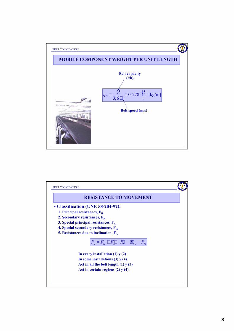
RESISTANCE TO MOVEMENT
• Classification (UNE 58-204-92):1. Principal resistances, FH2. Secondary resistances, FN3. Special principal resistances, FS14. Special secondary resistances, FS25. Resistances due to inclination, FSt
1 2u H N S S StF F F F F F= + + + +
In every installation (1) y (2)
In some installations (3) y (4)
Act in all the belt length (1) y (3)
Act in certain regions (2) y (4)

9
BELT CONVEYORS II
RESISTANCE TO MOVEMENT
•Turning resistance due to the load idlers rollers, due to friction in the
bearings and joints in rollers.
•Belt friction resistance due to the rolling of the belt over the idlers rollers.
Principal resistance
[ ](2 ) cosH RO RU B GF f L g q q q q δ= ⋅ ⋅ ⋅ + + ⋅ + ⋅
Friction coefficient
Work run roller weight per unit length(kg/m)
Return rollers weight per unit length(kg/m)
Belt weight per unitlength (kg/m)
Load weight perunit length (kg/m)
Angle of theincline
0,050Friction
0,023 – 0,030Unfavourable
0,020Normal
0,018Favourable
Roller
Bearing
fStateType of
bearing
BELT CONVEYORS II
•Inertia resistance and friction due to material acceleration in the loading
point:
Material density(kg/m3)
RESISTANCE TO MOVEMENT
Secondary resistances
Material flux (m3/s)
0( )ba vF I v vρ= ⋅ ⋅ −
Belt speed (m/s)
Feed-in speed (m/s)
•Resistance due to material friction with feed-in chute sidewalls.

10
BELT CONVEYORS II
•Resistance of pulley bearings safe drive pulleys:
– For fabric belts:
–For metallic belts:
RESISTANCE TO MOVEMENT
Secondary resistances
•Resistance due to rolling belt effect over the pulleys:
1 9 (140 0.01 )F d
F BB D
= ⋅ ⋅ + ⋅ ⋅
1 12 (200 0.01 )F d
F BB D
= ⋅ ⋅ + ⋅ ⋅
Belt width(m)
Mean belt stress (N)
Belt thickness (m)
Pulley diameter(m)
00.005t T
dF F
D= ⋅ ⋅
Pulley applied forces (N)
Drive axle diameter (m)
BELT CONVEYORS II
•When L > 80 m ⇒⇒⇒⇒ FN < FH:
RESISTANCE TO MOVEMENT
Secondary resistances
[ ][ ]
(2 ) cos
(2 ) cos
H N L RO RU B G
C RO RU B G
F F f C L g q q q q
f L g q q q q
δδ
+ = ⋅ ⋅ ⋅ ⋅ + + ⋅ + ⋅ =
= ⋅ ⋅ ⋅ + + ⋅ + ⋅
Friction coefficient Load weight perunit length (kg/m)
Incline angle
Belt weight per unitlength (kg/m)
Return run idler rollers weight per unitlength (kg/m)
Work run idler rollers weight per unitlenght (kg/m)
Corrected belt length (m)

11
BELT CONVEYORS II
LENGTH CORRECTION FACTOR
Shorter belts need more power to overcome friction resistances than longer belt conveyors.
Corrected belt length (m):
c LL C L= ⋅
1.051.11.21.31.41.51.61.71.822.2CL
500400320250200160125100806350Belt length(m)
2.42.62.93.23.644.55.15.96.65.69CL
4032252016131086543Belt length (m)
Correction factor
BELT CONVEYORS II
RESISTANCE TO MOVEMENT
Special principal resistance
•Toe resistance due to oblique belt position because of the loading rollers:
– 3 roller picking idler of the same length in the work run:
–
– 2 roller picking idler for the return run:
( ) coso B GF C L q q g senµ δ∈ ∈ ∈= ⋅ ⋅ ⋅ + ⋅ ⋅ ⋅ ∈
cos coso BF L q g senµ λ δ∈ ∈= ⋅ ⋅ ⋅ ⋅ ⋅ ⋅ ∈
Value:
- 0,4 for an angle of 30º
- 0,5 for an angle of 45º
Friction coefficient between
the belt and the idler rollers : 0,3 – 0,4
Longitud de la instalación con rodillos
portantes convergentes (m)
Belt weight per unit length(kg/m)
Load weight per unitlength (kg/m)
Toe angle (degrees)

12
BELT CONVEYORS II
RESISTANCE TO MOVEMENT
Special principal resistance
•Resistance due to friction with feed-in chute sidewalls, or with the
longitudinal guide rails, when they take place along the total belt length:
2
2
2 2
1
vgL
I e g lF
v b
µ ⋅ ⋅ ⋅ ⋅=⋅
Friction coefficientbetween the material andthe guides: 0,5 – 0,7
Transported flux (m3/s)
Weight volume not tared(kg/m3)
Transport length betweenguide rails (m)
Belt width between guide rails (m)
BELT CONVEYORS II
RESISTANCE TO MOVEMENT
Special secondary resistances
•Resistance due to friction between the cleaning systems and the belt:
•Resistance due to the friction between the chute sidewalls or with guide
rails when they only take place over a limited belt length :
Contact surface between thebelt and the cleaning system
(m2)
3rF A p µ= ⋅ ⋅
Pressure between the cleaningsystem and the belt (N/m2)
Friction coefficient between thecleaning system and the belt
a aF B k= ⋅
Belt width (m)Scraping factor = 1500 N/m

13
BELT CONVEYORS II
RESISTANCE TO MOVEMENT
Resistance due to slopes
St GF q H g= ⋅ ⋅
Load weight per unitlenght (kg/m)
Installationheight (m)
BELT CONVEYORS II
POWER OF THE DRIVE PULLEY
Drive pulley power
Force opposed to movement (N)
Belt speed (m/s)
A uP F v= ⋅
• For powered belts:
1
Am
PP
η=

14
BELT CONVEYORS II
TRANSPORT CAPACITY
3600Q v A kγ= ⋅ ⋅ ⋅ ⋅Transport capacity(t/hora)
Speed (m/s)
Cross section of material over the belt (m2)
Material specificweight (t/m3)
Reduction capacity coefficient due to incline
0,810,850,890,910,930,950,970.,980,991,0k
2018161412108642Incline
(degrees)
BELT CONVEYORS II
Depends on: - material fluidity
- transport conditions
TRANSPORT CAPACITY
•Cross section of the material over the belt depends on:
– Effective width (b) of the belt is function of the real width B:
•
•
– The number, arrangement and dimensions of the rollers.
– The dynamic built-in shape of the material over the belt is limited by a
parabolic curve, characterised by a dynamic slope angle θθθθ.
0.9 0.05 for B 2 mb B= ⋅ − ≤0.2 for B> 2 mb B= −
One roller Two rollers Three rollers
1 2S S S= +( )21 3 3( ) cos
6
tgS l b l
θλ= + − ⋅ ⋅
( )332 3
( ) 1sin
2 cos 2
b lb lS l λ
λ− − = + ⋅ ⋅ ⋅
Pickingangle

15
BELT CONVEYORS II
TRANSPORT CAPACITY
• Uniform material size (cereals, granules or milled stones) do not influence
belt width.
• Non classified materials (materials obtained in quarries or mines)
influence on belt width:
–Maximum material size.
– Fine and coarse-grain percentage.
• It may occur that for little capacities the belt width is big ⇒⇒⇒⇒ not
economic
• Belt width as a function of the maximum grain size:
53θ ≤ 20º
10620º ≤ θ ≤ 30º
100 % coarse10 % coarse, 90 % finesDynamic slope angle
BELT CONVEYORS II
TRANSPORT CAPACITY
• The belt speed has to be as big as possible so that width is short.
• Speed depends on material properties:
– Fluidity. Dust risk.
– Abrasion. Belt cut risk.
– Friable. Material split risk.
– Size. Great impacts on the belt take place for big sizes and heavy ones, thus
weakening the belt.
1,05 – 1,68Any widthNon abrasive
2,09
3,35
4,19
5,24
500
650 a 1000
1200 a 1200
1400 a 2400
Coal, clay pan, soft
minerals and soils, grinned
stones of little size
2,62
3,35
4,19
5,24
500
650 y 800
1000 y 1200
1400 y 2400
Grains and other materials
that have a good fluidity
and are not abrasive
V (m/s)B (mm)Material
0,3 a 0,6Any width
Discharge belts, flat or picking
for fine non abrasive materials
or medially abrasive
1,31 a 2,09Any widthPrepared cast-iron sands or
compacted
1,68
2,09
3,35
500
650 y 800
1000 a 2400
Minerals with sharp edge, hard
and heavy, grinned stones of
little size
V (m/s)B (mm)Material

16
BELT CONVEYORS II
TRANSPORT CAPACITY
900
0,2536
878
0,2467
840
0,2368
798
0,2240
738
0,2071
680
0,1903
351
0,09801400
654
0,1828
638
0,1777
610
0,1705
580
0,1612
537
0,1491
494
0,1370
255
0,07101200
445
0,1236
434
0,1205
415
0,1152
394
0,1094
365
0,1013
336
0,0933
173
0,04801000
276
0,0766
269
0,0747
258
0,0716
244
0,0677
227
0,0630
208
0,0577
108
0,0300800
176
0,0488
172
0,0477
164
0,0455
156
0,0433
144
0,0400
133
0,0369
69
0,0191650
98
0,0272
95
0,0263
91
0,0252
87
0,0241
80
0,0222
74
0,0205
38
0,0105500
1190
0,3355
45º
1160
0,3264
40º
1110
0,3134
35º
1055
0,2965
30º
1600
B\λ
464
0,1294
0º
976
1055
25º
898
0,2519
20º
Capacity in m3/hourfor v = 1 m/s
Cross section in m2
5,244,193,352,622,091,681,311,050,840,66
• Standard speeds in m/s (DIN 22101)
• For horizontal belt conveyors:
BELT CONVEYORS II
TRANSPORT CAPACITY
Belt geometry:
• L = 805 m, vertical extent = 150 m, incline = 10,73º
• For the previous incline, the capacity reduction coefficient k = 0,95
• Picking angle = 35º
Capacity to be transported: 1500 T/hour
EXAMPLE
Limestone
•Specific weight = 1,4 T/m3
•Particle size:
•10% of coarse, maximum size: 250 mm
•Dynamic slope angle: 15º
•Not abrasive, friable but no reduction in
price, due to a needed later grinding
¿Speed?
¿Belt width?

17
BELT CONVEYORS II
TRANSPORT CAPACITY
EXAMPLE
53θ ≤ 20º
10620º ≤ θ ≤ 30º
100 % coarse10 % coarse, 90 % fineDynamic slope angle
θ=15θ=15θ=15θ=15º
Maximum grain size 250 mm:
B = 3 ⋅⋅⋅⋅ Maximum size = 3 ⋅⋅⋅⋅ 250 = 750 mm
B=800 mm
0,810,850,890,910,930,950,970.,980,991,0K
2018161412108642Slope angle
(degrees)
BELT CONVEYORS II
TRANSPORT CAPACITY
EXAMPLE
900
0,2536
878
0,2467
840
0,2368
798
0,2240
738
0,2071
680
0,1903
351
0,09801400
654
0,1828
638
0,1777
610
0,1705
580
0,1612
537
0,1491
494
0,1370
255
0,07101200
445
0,1236
434
0,1205
415
0,1152
394
0,1094
365
0,1013
336
0,0933
173
0,04801000
276
0,0766
269
0,0747
258
0,0716
244
0,0677
227
0,0630
208
0,0577
108
0,0300800
176
0,0488
172
0,0477
164
0,0455
156
0,0433
144
0,0400
133
0,0369
69
0,0191650
98
0,0272
95
0,0263
91
0,0252
87
0,0241
80
0,0222
74
0,0205
38
0,0105500
1190
0,3355
45º
1160
0,3264
40º
1110
0,3134
35º
1055
0,2965
30º
1600
B\λ
464
0,1294
0º
976
1055
25º
898
0,2519
20º
800 mmB =
35ºλ =
Qv1 = 258 m3/s
For 1 m/s:

18
BELT CONVEYORS II
TRANSPORT CAPACITY
EXAMPLE
[ ]3
3600 t/h
3600 m /hv
Q v A k
QQ v A k
γ
γ
= ⋅ ⋅ ⋅ ⋅
= = ⋅ ⋅ ⋅
– Because Av1 = Av2:
312 2 2
1 1
2 2
2583,35 0,95 821m /hou
< 1500 t/ho
r1 1
1150 t/ho rur u
vv
v
QQ v k
v k
Q Qγ
= ⋅ ⋅ = ⋅ ⋅ =⋅ ⋅
= ⋅ =
1,05 – 1,68Any widthNon abrasive
2,09
3,35
4,19
5,24
500
650 a 1000
1200 a 1200
1400 a 2400
Coal, clay pan, soft
minerals and soils, grinned
stones of little size
2,62
3,35
4,19
5,24
500
650 y 800
1000 y 1200
1400 y 2400
Grains and other materials
that have a good fluidity
and are not abrasive
V (m/s)B (mm)Material
BELT CONVEYORS II
TRANSPORT CAPACITY
EXAMPLE
• We select B = 1000 mm
900
0,2536
878
0,2467
840
0,2368
798
0,2240
738
0,2071
680
0,1903
351
0,09801400
654
0,1828
638
0,1777
610
0,1705
580
0,1612
537
0,1491
494
0,1370
255
0,07101200
445
0,1236
434
0,1205
415
0,1152
394
0,1094
365
0,1013
336
0,0933
173
0,04801000
276
0,0766
269
0,0747
258
0,0716
244
0,0677
227
0,0630
208
0,0577
108
0,0300800
176
0,0488
172
0,0477
164
0,0455
156
0,0433
144
0,0400
133
0,0369
69
0,0191650
98
0,0272
95
0,0263
91
0,0252
87
0,0241
80
0,0222
74
0,0205
38
0,0105500
1190
0,3355
45º
1160
0,3264
40º
1110
0,3134
35º
1055
0,2965
30º
1600
B\λ
464
0,1294
0º
976
1055
25º
898
0,2519
20º

19
BELT CONVEYORS II
TRANSPORT CAPACITY
EXAMPLE
• We select B = 1000 mm
5,244,193,352,622,091,681,311,050,840,66
• Standard speeds in m/s (DIN 22101)
v=3,35 m/s
So as not to over design
1,05 – 1,68Any widthNon abrasive
2,09
3,35
4,19
5,24
500
650 a 1000
1200 a 1200
1400 a 2400
Coal, clay pan, soft
minerals and soils, grinned
stones of little size
2,62
3,35
4,19
5,24
500
650 y 800
1000 y 1200
1400 y 2400
Grains and other materials
that have a good fluidity
and are not abrasive
V (m/s)B (mm)Material
BELT CONVEYORS II
TRANSPORT CAPACITY
EXAMPLE
• Selecting B = 1000 mm⇒⇒⇒⇒ Qv1 = 415 m3/h y v2 = 3,35 m/s
312 2 2
1 1
2 2
4153,35 0,95 1320,7m /hora
1 1
1849 t/hour
vv
v
QQ v k
v k
Q Qγ
= ⋅ ⋅ = ⋅ ⋅ =⋅ ⋅
= ⋅ =
OK
B = 1000 mm and v = 3,35 m/s