Embed Size (px)
Citation preview
CS02CS05CSE05CS1CSE1CS1HP
CS2CSE2CS3CS5CS10
BetriebsanleitungInstruction Manual
capaNCDT 6019
MICRO-EPSILON MESSTECHNIKGmbH & Co. KGKönigbacher Strasse 15
94496 Ortenburg / Germany
Tel. 08542/168-0Fax 08542/168-90e-mail [email protected]
Zertifiziert nach DIN EN ISO 9001: 2008Certified acc. to DIN EN ISO 9001: 2008
Berührungsloses kapazitives Wegmesssystem
Non-contact Capacitive Displacement Measuring
Deu
tsch
capaNCDT 6019
Inhalt
1. Sicherheit .................................................................................................................................... 51.1 Verwendete Zeichen .......................................................................................................................................... 51.2 Warnhinweise ..................................................................................................................................................... 51.3 Hinweise zur CE-Kennzeichnung ...................................................................................................................... 61.4 Bestimmungsgemäße Verwendung .................................................................................................................. 61.5 Bestimmungsgemäßes Umfeld ......................................................................................................................... 7
2. Funktionsprinzip, Technische Daten ......................................................................................... 82.1 Messprinzip ........................................................................................................................................................ 82.2 Aufbau ................................................................................................................................................................ 92.3 Technische Daten ............................................................................................................................................. 10
3. Lieferung ................................................................................................................................... 113.1 Lieferumfang .................................................................................................................................................... 113.2 Lagerung .......................................................................................................................................................... 11
4. Installation und Montage ......................................................................................................... 124.1 Vorsichtsmaßnahmen ...................................................................................................................................... 124.2 Sensor .............................................................................................................................................................. 124.2.1 Radiale Punktklemmung mit Madenschraube ................................................................................................ 124.2.2 Umfangsklemmung .......................................................................................................................................... 134.2.3 Maßzeichnungen Sensoren ............................................................................................................................. 134.3 Sensorkabel und Controller ............................................................................................................................. 154.4 Spannungsversorgung und Signalausgang ................................................................................................... 174.5 Elektronik, Masseverbindung, Erdung ............................................................................................................ 17
5. Betrieb ...................................................................................................................................... 18
6. Wartung ..................................................................................................................................... 19
7. Haftung für Sachmängel .......................................................................................................... 20
8. Außerbetriebnahme, Entsorgung ............................................................................................ 21
9. Anhang ...................................................................................................................................... 219.1 Zubehör ............................................................................................................................................................ 219.2 Serviceleistungen ............................................................................................................................................. 21

capaNCDT 6019
Seite 5
Sicherheit
Deu
tsch
capaNCDT 6019
Sicherheit1.
Die Sensorhandhabung setzt die Kenntnis der Betriebsanleitung voraus.
Verwendete Zeichen1.1 In dieser Betriebsanleitung werden folgende Bezeichnungen verwendet:
Zeigt eine gefährliche Situation an, die zu geringfügigen oder mittelschweren Verlet-zungen führt, falls diese nicht vermieden wird.
Zeigt eine Situation an, die zu Sachschäden führen kann, falls diese nicht vermieden wird.
Zeigt eine ausführende Tätigkeit an.
i Zeigt einen Anwendertipp an.
Warnhinweise1.2 Unterbrechen Sie die Spannungsversorgung vor Berührung der Sensoroberfläche.
Statische Entladung >
Verletzungsgefahr >
Schließen Sie die Spannungsversorgung und das Anzeige-/Ausgabegerät nach den Sicherheitsvorschriften für elektrische Betriebsmittel an.
Verletzungsgefahr >
Beschädigung oder Zerstörung des Sensors und/oder des Controllers >
Vermeiden Sie Stöße und Schläge auf den Sensor und Controller.Beschädigung oder Zerstörung des Sensors und/oder des Controllers >
Versorgungsspannung darf angegebene Grenzen nicht überschreiten.Beschädigung oder Zerstörung des Sensors und/oder des Controllers >
Schützen Sie das Sensorkabel vor Beschädigung.Zerstörung des Sensors, Ausfall des Messsystems >

Seite 6
Sicherheit
capaNCDT 6019
Hinweise zur CE-Kennzeichnung1.3 Für das Messsystem capaNCDT 6019 gilt: EMV-Richtlinie 2004/108/EG
Produkte, die das CE-Kennzeichen tragen, erfüllen die Anforderungen der EMV-Richtlinie 2004/108/EG „Elek-tromagnetische Verträglichkeit“ und die dort aufgeführten harmonisierten europäischen Normen (EN). Die EU-Konformitätserklärung wird gemäß der EU-Richtlinie, Artikel 10, für die zuständige Behörde zur Verfügung gehalten bei MICRO-EPSILON MESSTECHNIKGmbH & Co. KGKönigbacher Straße 1594496 Ortenburg
Das Messsystem ist ausgelegt für den Einsatz im Industriebereich und erfüllt die Anforderungen gemäß den Normen
DIN EN 61326-1: 2006-10 -DIN 61326-2-3: 2007-05 -
Das Messsystem erfüllt die Anforderungen, wenn bei Installation und Betrieb die in der Betriebsanleitung beschriebenen Richtlinien eingehalten werden.
Bestimmungsgemäße Verwendung1.4 Das Messsystem capaNCDT 6019 ist für den Einsatz im Industriebereich konzipiert. Es wird eingesetzt zur -
Weg-, Abstands-, und Verschiebungsmessung �Positionserfassung von Bauteilen oder Maschinenkomponenten �
Das Messsystem darf nur innerhalb der in den technischen Daten angegebenen Werte betrieben werden - , siehe Kap. 2.3.
- Setzen Sie das Messsystem so ein, dass bei Fehlfunktionen oder Totalausfall des Sensors keine Personen gefährdet oder Maschinen beschädigt werden. Treffen Sie bei sicherheitsbezogenener Anwendung zusätzlich Vorkehrungen für die Sicherheit und zur -Schadensverhütung.

Seite 7
Sicherheit
Deu
tsch
capaNCDT 6019
Bestimmungsgemäßes Umfeld1.5 Betriebstemperatur: +10 ... +50 °C -Lagertemperatur: -10 °C ... +75 °C -Luftfeuchtigkeit: 5 - 95 % (nicht kondensierend) -Umgebungsdruck: Atmosphärendruck -EMV: Gemäß DIN EN 61326-1: 2006-10 - DIN 61326-2-3: 2007-05Der Raum zwischen Sensoroberfläche und Messobjekt muss eine konstante Dielektrizitätszahl haben und -darf nicht verschmutzt sein (z. B. Wasser, Abrieb, Staub, etc.)
Seite 8
Funktionsprinzip, Technische Daten
capaNCDT 6019
Funktionsprinzip, Technische Daten2.
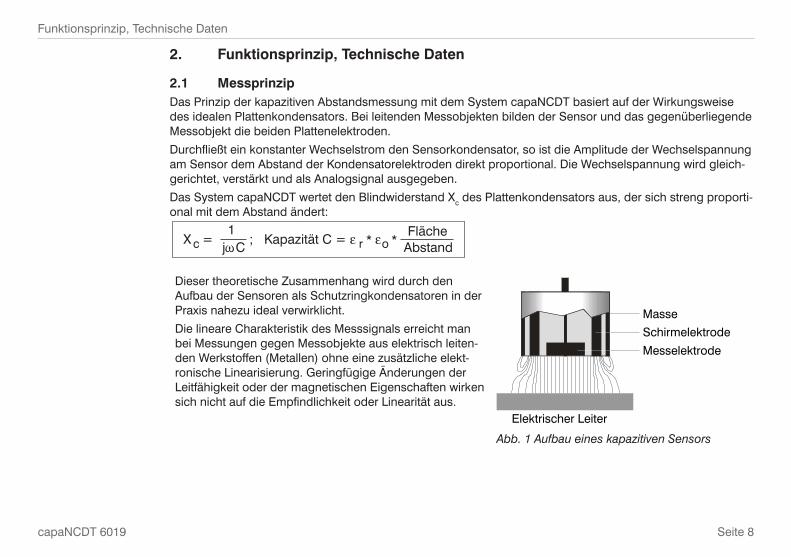
Messprinzip2.1 Das Prinzip der kapazitiven Abstandsmessung mit dem System capaNCDT basiert auf der Wirkungsweise des idealen Plattenkondensators. Bei leitenden Messobjekten bilden der Sensor und das gegenüberliegende Messobjekt die beiden Plattenelektroden.
Durchfließt ein konstanter Wechselstrom den Sensorkondensator, so ist die Amplitude der Wechselspannung am Sensor dem Abstand der Kondensatorelektroden direkt proportional. Die Wechselspannung wird gleich-gerichtet, verstärkt und als Analogsignal ausgegeben.
Das System capaNCDT wertet den Blindwiderstand Xc des Plattenkondensators aus, der sich streng proporti-onal mit dem Abstand ändert:
X = ; Kapazität C = * * c1
jCFläche
Abstandr o
Dieser theoretische Zusammenhang wird durch den Aufbau der Sensoren als Schutzringkondensatoren in der Praxis nahezu ideal verwirklicht.
Die lineare Charakteristik des Messsignals erreicht man bei Messungen gegen Messobjekte aus elektrisch leiten-den Werkstoffen (Metallen) ohne eine zusätzliche elekt-ronische Linearisierung. Geringfügige Änderungen der Leitfähigkeit oder der magnetischen Eigenschaften wirken sich nicht auf die Empfindlichkeit oder Linearität aus.
Elektrischer Leiter
Masse
Schirmelektrode
Messelektrode
Aufbau eines kapazitiven SensorsAbb. 1

Seite 9
Funktionsprinzip, Technische Daten
Deu
tsch
capaNCDT 6019
Aufbau2.2 Das in einem Aluminiumgehäuse eingebaute berührungslose Einkanal-Messsystem des capaNCDT 6019 setzt sich zusammen aus:
Controller mit integriertem Sensorkabel und -Sensor. -
Im Controller befindet sich die Signalaufberei-tungselektronik mit Oszillator, Demodulator und integriertem Vorverstärker.Der Controller enthält einen 4-poligen Schraub-klemmanschlusss, Verpolungsschutz und verschiedene Schutzelemente der Anschlüsse, die zur Einhaltung der EMV-Richtlinien notwendig sind.Die Messwertanzeige ist nur extern möglich.
Sensor
Sensorkabel
Controller
Versorgungsspannung,Ausgangssignal
Messsystem capaNCDT 6019Abb. 2

Seite 10
Funktionsprinzip, Technische Daten
capaNCDT 6019
2.3 Technische DatenController-Typ DT6019
Auflösung statisch 0,015 % d.M.
Auflösung dynamisch 0,1 % d.M. (500 Hz)
Grenzfrequenz 0,5 kHz
Linearität ±1 % d.M.
Max. Empfindlichkeitsabweichung ±0,5 % d.M.
Langzeitstabilität ≤ 0,05 % d.M./Monat
Synchronbetrieb möglich nein
Isolatormessung nein
Temperaturstabilität ±0,05 % d.M. / °C
Betriebstemperatur +10 °C ... +50 °C
Lagertemperatur -10 °C ... +75 °C
Versorgung ±12 …±18 VDC
Stromaufnahme -7 / +8 mA
Ausgang 0 bis 10 V (innerhalb des Messbereichs), kurzschlussfest
Gewicht 60 g
Sensoren alle Sensoren mit Buchse, außer CS005
Elektromagnetische Verträglichkeit (EMV) DIN EN 61326-1: 2006-10 und DIN 61326-2-3: 2007-05
d. M. = des Messbereiches

Seite 11
Lieferung
Deu
tsch
capaNCDT 6019
Lieferung3.
Lieferumfang3.1 1 Controller mit Sensorkabel
1 Sensor
1 Betriebsanleitung
Nehmen Sie die Teile des Messsystems vorsichtig aus der Verpackung und transportieren Sie sie so weiter, dass keine Beschädigungen auftreten können.
Prüfen Sie die Lieferung nach dem Auspacken sofort auf Vollständigkeit und Transportschäden. Bei Schäden oder Unvollständigkeit wenden Sie sich bitte sofort an den Lieferanten.
Lagerung3.2 Lagertemperatur: -10 °C bis +75 °C
Luftfeuchte: 5 bis 95 % RH (nicht kondensierend)

Seite 12
Installation und Montage
capaNCDT 6019
Installation und Montage4.
Vorsichtsmaßnahmen4.1 Auf den Kabelmantel des Sensorkabels dürfen keine scharfkantigen oder schweren Gegenstände einwirken.
Schützen Sie das Kabel in Bereichen mit erhöhtem Druck grundsätzlich vor Druckbelastung.
Der minimale Biegeradius beträgt 20 mm. Vermeiden Sie auf jeden Fall Knicke.
Überprüfen Sie die Steckverbindungen auf festen Sitz.
i Ein beschädigtes Kabel kann nicht repariert werden.
Sensor4.2 Die Sensoren des capaNCDT6019 können freistehend oder bündig montiert werden.
Achten Sie bei der Montage darauf, dass die polierte Sensorstirnfläche nicht zerkratzt wird.
Radiale Punktklemmung mit Madenschraube4.2.1
Diese einfache Befestigungsart ist nur bei kraft- und vibrationsfreiem Einbauort zu empfehlen. Die Maden-schraube muss aus Kunststoff sein, damit das Sensorgehäuse nicht beschädigt oder verformt werden kann.
Maden-schraube
Radiale Punktklemmung mit MadenschraubeAbb. 3
Verwenden Sie keine Metallmadenschrauben!Gefahr der Beschädigung des Sensors >
Seite 13
Installation und Montage
Deu
tsch
capaNCDT 6019
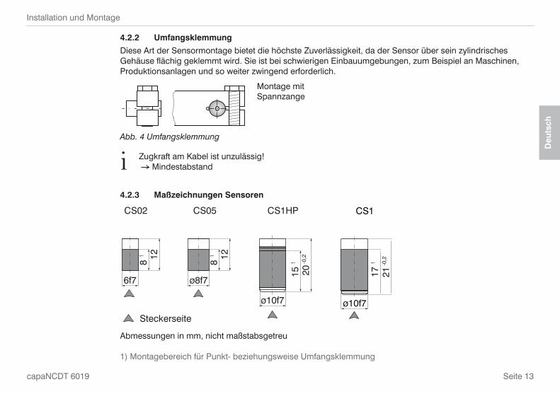
Umfangsklemmung4.2.2
Diese Art der Sensormontage bietet die höchste Zuverlässigkeit, da der Sensor über sein zylindrisches Gehäuse flächig geklemmt wird. Sie ist bei schwierigen Einbauumgebungen, zum Beispiel an Maschinen, Produktionsanlagen und so weiter zwingend erforderlich.
Montage mit Spannzange
UmfangsklemmungAbb. 4
i Zugkraft am Kabel ist unzulässig! Mindestabstand
Maßzeichnungen Sensoren4.2.3
CS05
ø8f7
8 1 12
Steckerseite
CS02
8 1 12
6f7
ø10f7
CS1HP
15 1
20 -0
,2ø10f7
CS1
17 1
21 -0
,2
Abmessungen in mm, nicht maßstabsgetreu
1) Montagebereich für Punkt- beziehungsweise Umfangsklemmung

Seite 14
Installation und Montage
capaNCDT 6019
M=1:2
ø20h7
20 1
24 -0
,2
Steckerseite
CS2
ø30h7
ø20h7
16,5
1
24 -0
,2
CS3
M=1:2
ø20h7
24 -0
,2
16,5
1
ø40h7
CS5
M=1:2
16,5
1
24 -0
,2
ø20h7
ø60h7
M=1:2
CS10
CSE2CSE1
9 12ø8f7ø7,7
Ø13,7Ø14h7
18,5 22Steckerseite
CSE05
129
ø6f7ø5,7
Abmessungen in mm, nicht maßstabsgetreu
1) Montagebereich für Punkt- beziehungsweise Umfangsklemmung

Seite 15
Installation und Montage
Deu
tsch
capaNCDT 6019
Sensorkabel und Controller4.3 Der Sensor wird mit dem Controller über das integrierte Sensorkabel verbunden. Der Anschluss erfolgt durch Stecken. Die Steckverbindung verriegelt selbstständig. Der feste Sitz kann durch Ziehen am Steckergehäuse (Kabelbuchse) geprüft werden. Durch Ziehen an der gerändelten Gehäusehülse der Kabelbuchse öffnet die Verriegelung und die Steckverbindung kann geöffnet werden.
DT6019-C DT6019-B
Winkel-Stecker Winkel-Stecker geeignet für Sensoren
• CS02 / CS05
• CS1 / CS2 / CS3 / CS5 / CS10
16
8
13,1
16,9
Kabellänge ca. 100Ø
4
Ø6Ø5,4
DT6019-C
Maßzeichnung Sensorkabel mit Winkel-Stecker für die Sensoren CS02 und CS05Abb. 5
i Biegeradius Sensorkabel Einmalig: 7 mm Ständig: 20 mm
Abmessungen in mm, nicht maßstabsgetreu

Seite 16
Installation und Montage
capaNCDT 6019
Kabellänge ca. 100
24,2
Ø2,
2
Ø9
10
30,6
Ø10
3
1x45°DT6019-B
6,5 10
72,5
66 3,25
8,2
21
82440
18
StromversorgungSignalausgang
4 Befestigungsbohrungen für Schrauben M3
Maßzeichnung Controller und Sensorkabel mit Winkelstecker für die Sensoren CS1, CS2, CS3, CS5 und CS10Abb. 6
Abmessungen in mm, nicht maßstabsgetreu
Seite 17
Installation und Montage
Deu
tsch
capaNCDT 6019
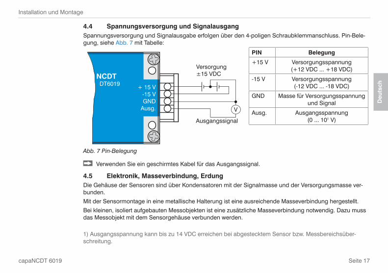
4.4 Spannungsversorgung und SignalausgangSpannungsversorgung und Signalausgabe erfolgen über den 4-poligen Schraubklemmanschluss. Pin-Bele-gung, siehe Abb. 7 mit Tabelle:
Versorgung±15 VDC
Ausgangssignal
V
NCDT DT6019 + 15 V
-15 VGND
Ausg.
PIN Belegung
+15 V Versorgungsspannung (+12 VDC ... +18 VDC)
-15 V Versorgungsspannung (-12 VDC ... -18 VDC)
GND Masse für Versorgungsspannung und Signal
Ausg. Ausgangsspannung (0 ... 101 V)
Abb. 7 Pin-Belegung
Verwenden Sie ein geschirmtes Kabel für das Ausgangssignal.
Elektronik, Masseverbindung, Erdung4.5 Die Gehäuse der Sensoren sind über Kondensatoren mit der Signalmasse und der Versorgungsmasse ver-bunden.
Mit der Sensormontage in eine metallische Halterung ist eine ausreichende Masseverbindung hergestellt.
Bei kleinen, isoliert aufgebauten Messobjekten ist eine zusätzliche Masseverbindung notwendig. Dazu muss das Messobjekt mit dem Sensorgehäuse verbunden werden.
1) Ausgangsspannung kann bis zu 14 VDC erreichen bei abgestecktem Sensor bzw. Messbereichsüber-schreitung.

Seite 18
Betrieb
capaNCDT 6019
Betrieb5.
Schließen Sie die Anzeige-/Ausgabegeräte über die Schraubklemmverbindung an, bevor Sie das Gerät an die Stromversorgung anschließen und diese einschalten, siehe Kap. 4.4.
Das Messsystem wird kalibriert ausgeliefert. Eine Kalibrierung durch den Anwender ist nicht erforderlich.
i Lassen Sie das Messsystem nach Anlegen der Spannungsversorgung ca. 10 Minuten warmlaufen.
10 V
Sensor
0 % Messbereich 100 %
2
0 V1
Ausgangs-spannung
Mess-objekt
Verlauf der Ausgangsspannung im MessbereichAbb. 8
Unterbrechen Sie die Spannungsversorgung vor Berührung der Sensoroberfläche.Statische Entladung >
Verletzungsgefahr >
1 = Messbereichsanfang
2 = Messbereichsende

Seite 19
Wartung
Deu
tsch
capaNCDT 6019
Wartung6.
Achten Sie darauf, dass stets eine saubere Sensoroberfläche vorhanden ist.
Schalten Sie vor der Reinigung die Versorgungsspannung ab.
Verwenden Sie zur Reinigung ein feuchtes Tuch; reiben Sie anschließend die Sensoroberfläche trocken.
Unterbrechen Sie die Spannungsversorgung vor Berührung der Sensoroberfläche.Statische Entladung >
Verletzungsgefahr >
Bei einem Defekt des Controllers, des Sensors oder des Sensorkabels senden Sie bitte die betreffenden Teile zur Reparatur oder zum Austausch ein. Bei Störungen, deren Ursachen nicht eindeutig er-kennbar sind, senden Sie bitte immer das gesamte Messsystem an
MICRO-EPSILON MESSTECHNIK GmbH & Co. KG Königbacher Str. 15 D-94496 Ortenburg Telefon: +49/8542/168 - 0 Fax: +49/8542/168 - 90
[email protected] www.micro-epsilon.de
Sensoren des selben Typs können ohne Nachkalibrierung des Controllers getauscht werden.

Seite 20
Haftung für Sachmängel
capaNCDT 6019
Haftung für Sachmängel7.
Alle Komponenten des Gerätes wurden im Werk auf die Funktionsfähigkeit hin überprüft und getestet.
Sollten jedoch trotz sorgfältiger Qualitätskontrolle Fehler auftreten, so sind diese umgehend an MICRO-EPSI-LON oder den Händler zu melden.
Die Haftung für Sachmängel beträgt 12 Monate ab Lieferung. Innerhalb dieser Zeit werden fehlerhafte Teile, ausgenommen Verschleißteile, kostenlos instand gesetzt oder ausgetauscht, wenn das Gerät kostenfrei an MICRO-EPSILON eingeschickt wird.
Nicht unter die Haftung für Sachmängel fallen solche Schäden, die durch unsachgemäße Behandlung oder Gewalteinwirkung entstanden oder auf Reparaturen oder Veränderungen durch Dritte zurückzuführen sind.
Für Reparaturen ist ausschließlich MICRO-EPSILON zuständig.
Weitergehende Ansprüche können nicht geltend gemacht werden. Die Ansprüche aus dem Kaufvertrag blei-ben hierdurch unberührt.
MICRO-EPSILON haftet insbesondere nicht für etwaige Folgeschäden.
Die Ansprüche aus dem Kaufvertrag belieben hierdurch unberührt.
Im Interesse der Weiterentwicklung behalten wir uns das Recht auf Konstruktionsänderungen vor.

Seite 21
Außerbetriebnahme, Entsorgung
Deu
tsch
capaNCDT 6019
Außerbetriebnahme, Entsorgung8.
Entfernen Sie die elektrischen Anschlüsse für die Versorgungsspannung und Ausgangsspannung am Controller.
Das capaNCDT6019 ist entsprechend der Richtlinie 2002/95/EG, „RoHS“, gefertigt.
Führen Sie die Entsorgung entsprechend den gesetzlichen Bestimmungen durch (siehe Richtlinie 2002/96/EG).
Anhang9.
Zubehör9.1 PS100/230/15 Einbau-Netzteil, Eingang 230 VAC, Ausgang ±VDC/ 500 mA
Serviceleistungen9.2 Funktions- und Linearitätsprüfung incl. 11-Punkte-Protokoll mit grafischer Darstellung und Nachkalibrierung.

capaNCDT 6019
Contents
1. Safety ........................................................................................................................................ 231.1 Symbols Used .................................................................................................................................................. 231.2 Warnings .......................................................................................................................................................... 231.3 Notes on CE Identification ............................................................................................................................... 241.4 Proper Use ....................................................................................................................................................... 241.5 Proper Environment ......................................................................................................................................... 24
2. Functional Principle, Technical Data ....................................................................................... 252.1 Measuring Principle ......................................................................................................................................... 252.2 Structure ........................................................................................................................................................... 262.3 Technical Data .................................................................................................................................................. 26
3. Delivery ..................................................................................................................................... 273.1 Unpacking ........................................................................................................................................................ 283.2 Storage ............................................................................................................................................................. 28
4. Installation and Assembly ........................................................................................................ 294.1 Precautionary Measures .................................................................................................................................. 294.2 Sensor .............................................................................................................................................................. 294.2.1 Sensor Radial Point Clamping with Grub Screw ............................................................................................. 294.2.2 Circumferential Clamping ................................................................................................................................ 304.2.3 Dimensional Drawings Sensors ....................................................................................................................... 304.3 Sensor Cable and Controller ........................................................................................................................... 324.4 Power Supply and Signal Output .................................................................................................................... 344.5 Electronics, Ground Connection, Earthing ...................................................................................................... 34
5. Operation .................................................................................................................................. 35
6. Maintenance ............................................................................................................................. 36
7. Warranty .................................................................................................................................... 37
8. Decommissioning, Disposal .................................................................................................... 38
9. Appendix ................................................................................................................................... 389.3 Accessories ...................................................................................................................................................... 389.4 Service .............................................................................................................................................................. 38
Page 23
Safety
Eng
lish
capaNCDT 6019
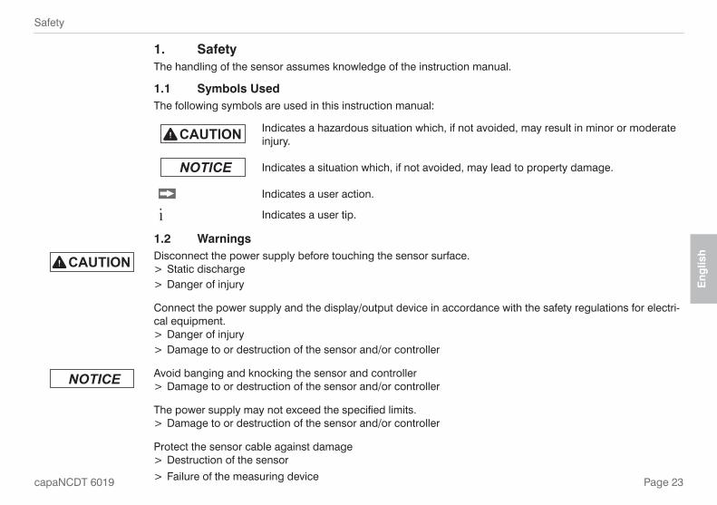
Safety1. The handling of the sensor assumes knowledge of the instruction manual.
Symbols Used1.1 The following symbols are used in this instruction manual:
Indicates a hazardous situation which, if not avoided, may result in minor or moderate injury.
Indicates a situation which, if not avoided, may lead to property damage.
Indicates a user action.
i Indicates a user tip.
Warnings1.2 Disconnect the power supply before touching the sensor surface.
Static discharge >Danger of injury >
Connect the power supply and the display/output device in accordance with the safety regulations for electri-cal equipment.
Danger of injury >Damage to or destruction of the sensor and/or controller >
Avoid banging and knocking the sensor and controllerDamage to or destruction of the sensor and/or controller >
The power supply may not exceed the specified limits.Damage to or destruction of the sensor and/or controller >
Protect the sensor cable against damageDestruction of the sensor >
F > ailure of the measuring device
Page 24
Safety
capaNCDT 6019
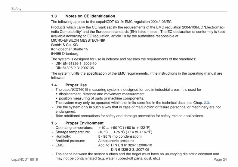
Notes on CE Identification1.3 The following applies to the capaNCDT 6019: EMC regulation 2004/108/EC
Products which carry the CE mark satisfy the requirements of the EMC regulation 2004/108/EC ‘Electromag-netic Compatibility’ and the European standards (EN) listed therein. The EC declaration of conformity is kept available according to EC regulation, article 10 by the authorities responsible atMICRO-EPSILON MESSTECHNIKGmbH & Co. KGKönigbacher Straße 1594496 Ortenburg
The system is designed for use in industry and satisfies the requirements of the standards:DIN EN 61326-1: 2006-10 -DIN 61326-2-3: 2007-05 -
The system fulfills the specification of the EMC requirements, if the instructions in the operating manual are followed.
Proper Use1.4 The capaNCDT6019 measuring system is designed for use in industrial areas. It is used for -
displacement, distance and movement measurement �position measuring of parts or machine components. �
The system may only be operated within the limits specified in the technical data - , see Chap. 2.3.Use the system only in such a way that in case of malfunction or failure personnel or machinery are not -endangered.Take additional precautions for safety and damage prevention for safety-related applications. -
Proper Environment1.5 Operating temperature: +10 ... +50 °C (+50 to +122 °F) -Storage temperature: -10 °C ... +75 °C (+14 to +167°F) -Humidity: 5 - 95 % (no condensation) -Ambient pressure: Atmospheric pressure -EMC: Acc. to DIN EN 61326-1: 2006-10 - DIN 61326-2-3: 2007-05The space between the sensor surface and the target must have an un-varying dielectric constant and -may not be contaminated (e.g. water, rubbed-off parts, dust, etc.)

Page 25
Functional Principle, Technical Data
Eng
lish
capaNCDT 6019
Functional Principle, Technical Data2.
Measuring Principle2.1 The principle of capacitive distance measurement with the capaNCDT system is based on the principle of the parallel plate capacitor. For conductive targets, the sensor and the target opposite form the two plate elec-trodes.
If a constant AC current flows through the sensor capacitor, the amplitude of the AC voltage at the sensor is proportional to the distance between the capacitor electrodes. The AC voltage is demodulated, amplified and output as an analog signal.
The capaNCDT system evaluates the reactance Xc of the plate capacitor which changes strictly in proportion to the distance.
X = ; capacitance C = * * c1
jC area
distancer o
This theoretical relationship is realized almost ideally in practice by designing the sensors as guard ring capacitors.
The linear characteristic of the measuring signal is achieved for electrically conductive target materials (metals) without any additional electronic linearization. Slight changes in the conductivity or magnetic proper-ties do not affect the sensitivity or linearity.
Electrical conductor
Ground
Screening electrode
Measuring electrode
Functional principle of the guard ring Fig. 1 capacitor
Page 26
Functional Principle, Technical Data
capaNCDT 6019
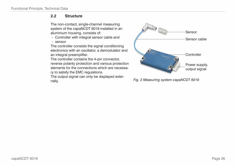
Structure2.2
The non-contact, single-channel measuring system of the capaNCDT 6019 installed in an aluminium housing, consists of:
Controller with integral sensor cable and -sensor. -
The controller consists the signal conditioning electronics with an oscillator, a demodulator and an integral preamplifier.The controller contains the 4-pin connector, reverse polarity protection and various protection elements for the connections which are necessa-ry to satisfy the EMC regulations.The output signal can only be displayed exter-nally.
Sensor
Sensor cable
Controller
Power supply,output signal
Measuring system capaNCDT 6019Fig. 2
Page 27
Functional Principle, Technical Data
Eng
lish
capaNCDT 6019
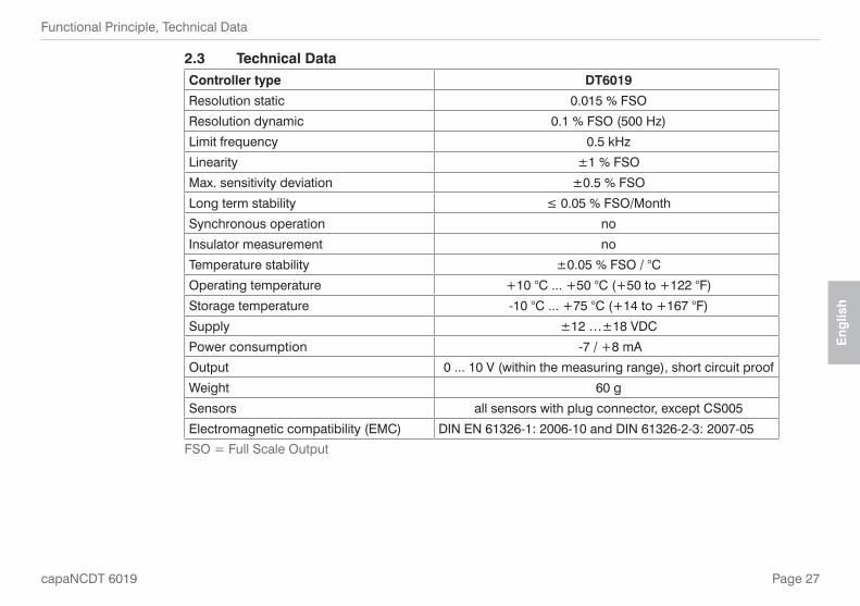
2.3 Technical DataController type DT6019
Resolution static 0.015 % FSO
Resolution dynamic 0.1 % FSO (500 Hz)
Limit frequency 0.5 kHz
Linearity ±1 % FSO
Max. sensitivity deviation ±0.5 % FSO
Long term stability ≤ 0.05 % FSO/Month
Synchronous operation no
Insulator measurement no
Temperature stability ±0.05 % FSO / °C
Operating temperature +10 °C ... +50 °C (+50 to +122 °F)
Storage temperature -10 °C ... +75 °C (+14 to +167 °F)
Supply ±12 …±18 VDC
Power consumption -7 / +8 mA
Output 0 ... 10 V (within the measuring range), short circuit proof
Weight 60 g
Sensors all sensors with plug connector, except CS005
Electromagnetic compatibility (EMC) DIN EN 61326-1: 2006-10 and DIN 61326-2-3: 2007-05
FSO = Full Scale Output
Page 28
Delivery
capaNCDT 6019
Delivery3.
Unpacking3.1 1 Controller with sensor cable
1 Sensor
1 Instruction manual
Remove the parts of the system carefully from the packaging and transport them in such a way that they are not damaged.
Check for completeness and shipping damages immediately after unpacking. In case of damage or missing parts, please contact the manufacturer or supplier.
Storage3.2 Storage temperature: -10 °C ... +75 °C (+14 to +167 °F)
Humidity: 5 up to 95 % RH (non condensing)

Page 29
Installation and Assembly
Eng
lish
capaNCDT 6019
Installation and Assembly4.
Precautionary Measures4.1 No sharp-edged or heavy objects may come into contact with the sensor cable sheath.
Protect the cable in pressurised rooms against pressure loads.
The minimum bending radius is 20 mm (.79 inch). Avoid kinks at all cost.
Check the connections for tight fit.
i A damaged cable cannot be repaired.
Sensor4.2 The sensors of the capaNCDT6019 may be mounted free-standing or flush.
When assembling, make sure that the polished sensor surface is not scratched.
Sensor Radial Point Clamping with Grub Screw4.2.1
This simple type of fixture is only recommended for a force and vibration-free installation position. The grub screw must be made of plastic so that it cannot damage or deform the sensor housing.
Grub screw
Radial point clamping with grub screwFig. 3
Do not use metal grub screws!Danger of damaging the sensor >

Page 30
Installation and Assembly
capaNCDT 6019
Circumferential Clamping4.2.2
This sensor mounting option offers maximum reliability because the sensor is clamped around its cylindrical housing. It is absolutely necessary in difficult installation environments, e.g. on machines, production plants etc.
Mounting with clamping ring
Circumferential clampingFig. 4
i Tension at the cable is inadmissible! Minimum distance
Dimensional Drawings Sensors4.2.3
Connector side
CS02
12
(.47
2)
ø6f7 (.236 dia.)
8 1
(.31
5)
ø8f7 (.314 dia.)
CS05
8 1
(.31
5)12
(.
472)
ø10f7 (.394 dia.)
CS1HP
15 1
(.59
0)
20 -0
,2
(.7
87 -0
08 )
CS1
ø10f7 (.394 dia.)
21
-0
2
(.8
26 -0
08)
17
1 (.
66
9)
Dimensions in mm (inches), not to scale
1) Adjustment area for radial point respectively circumferential clamping

Page 31
Installation and Assembly
Eng
lish
capaNCDT 6019
M=1:2ø20h7 (.79 dia.)
24 -0
.2
(.94
5) -0
.08
Connector side
CS2
ø30h7 (1.18 dia.)
ø20h7 (.79 dia.)
24 -0
,2
(.94
5) -0
.08
CS3
M=1:2
ø20h7 (.79 dia.)
ø40h7 (1.58 dia.)
CS5
M=1:2
16.5
1
24 -0
,2
ø20h7 (.79 dia.)
ø60h7 (2.36 dia.)
M=1:2
CS10
20 1 (
.787
)
16.5
1 ( .6
49)
16.5
1 ( .6
49)
24 -0
,2
(.94
5) -0
.08
CSE05
12 (
.47)
ø6f7(.24 dia.)
ø5.7 (.22)
9 (.
35)
CSE1
12 (
0.47
)
ø8f7 (0.31 dia.)
CSE2
ø14h7 (0.55 dia.)
18.5
(0.
73)
22 (
0.87
)
ø7.7 (0.30 dia.)
9 (0
.35)
ø13.7 (0.54 dia.)
Connector side
Dimensions in mm (inches), not to scale
1) Adjustment area for radial point respectively circumferential clamping
Dimension Fit tolerance µm
6f7 -10 -22
8f7 -13 -28
10f7 -13 -28
14f7 0 -18
20h7 0 -21
30h7 0 -25
40h7 0 -25
60h7 0 -30

Page 32
Installation and Assembly
capaNCDT 6019
Sensor Cable and Controller4.3 The sensor is connected to the controller by the integral sensor cable. The connection is made by simpleplugging. The connector locks automatically. The tight fit can be checked by pulling the connector housing(cable bushing). The lock can be released and the connector can be opened by pulling the knurled housingsleeve of the cable bushing.
DT6019-C DT6019-B
Angled connector Angled connector suitable for sensors
• CS02 / CS05
• CS1 / CS2 / CS3 / CS5 / CS10
16 (.63)8
(.3
1)
13.1
(.52
)
16.9
(.67
)
Cable length appr. 100
Ø5.4(.21 dia)
DT6019-C
Ø6 (.24 dia)
Ø4
(.16
dia
)
Dimensional drawing sensor cable with angled connector for the sensors CS02 and CS05Fig. 5
i Bending radius sensor cable Once: 7 mm Continuous: 20 mm
Dimensions in mm, not to scale

Page 33
Installation and Assembly
Eng
lish
capaNCDT 6019
Cable length appr. 100
24.2 (.95)
Ø2.
2 (.
09 d
ia.)
Ø9
(.35
dia
.)
10 (.39
)30.6
(1.
20)
Ø10(.39 dia)
3(.
12)
1x45°DT6019-B
6.5
(.26
)10 (.39
)
Dimensional drawing controller and sensor cable with angled connector for the sensors CS1, CS2, CS3, CS5 and CS10Fig. 6
72.5 (2.85)
66 (2.60) 3.25(.13)
8.2(.32)
21 (
.83)
8(.
31)
24 (
.94)
40 (
1.57
) 18 (.71
)
Power supplySignal output
4 Mounting holes for screws M3
Dimensions in mm (inches), not to scale
Page 34
Installation and Assembly
capaNCDT 6019
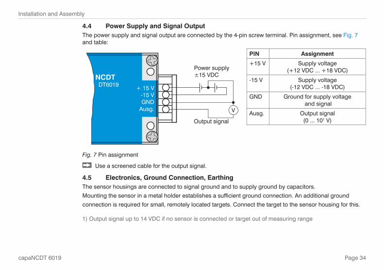
4.4 Power Supply and Signal OutputThe power supply and signal output are connected by the 4-pin screw terminal. Pin assignment, see Fig. 7 and table:
Power supply±15 VDC
Output signal
V
NCDT DT6019 + 15 V
-15 VGND
Ausg.
PIN Assignment
+15 V Supply voltage (+12 VDC ... +18 VDC)
-15 V Supply voltage (-12 VDC ... -18 VDC)
GND Ground for supply voltage and signal
Ausg. Output signal (0 ... 101 V)
Fig. 7 Pin assignment
Use a screened cable for the output signal.
Electronics, Ground Connection, Earthing4.5 The sensor housings are connected to signal ground and to supply ground by capacitors.
Mounting the sensor in a metal holder establishes a sufficient ground connection. An additional ground
connection is required for small, remotely located targets. Connect the target to the sensor housing for this.
1) Output signal up to 14 VDC if no sensor is connected or target out of measuring range

Page 35
Operation
Eng
lish
capaNCDT 6019
Operation5. Connect the display/output devices through the signal output socket, see Chap. 4.4, before connecting
the device to the power supply and switching on the power supply.
The measuring system is delivered calibrated. Calibration by the user is not necessary.
i Allow the measuring system to warm up for about 10 minutes before the first measurement.
10 V
Sensor
0 % Measuring range 100 %
2
0 V1
Outputvoltage
Target
Signal characteristic in the measuring rangeFig. 8
Disconnect the power supply before touching the sensor surface.Static discharge >
Danger of injury >
1 = Start of measuring range
2 = End of measuring range

Page 36
Maintenance
capaNCDT 6019
Maintenance6. Make sure that the sensor surface is always clean.
Switch off the power supply before cleaning.
Clean with a clamp cloth; then rub the sensor surface dry.
Disconnect the power supply before touching the sensor surface.Static discharge >
Danger of injury >
In the event of a defect on the controller, the sensor or the sensor cable please send us the effected parts for repair or exchange. In the case of faults the cause of which is not clearly identifiable, send the whole measuring system back to
MICRO-EPSILON MESSTECHNIK GmbH & Co. KG Königbacher Str. 15 D-94496 Ortenburg / Germany Telefon: +49/8542/168 - 0 Fax: +49/8542/168 - 90
[email protected] www.micro-epsilon.com
Sensors of the same type can be replaced without calibrating the controller.

Page 37
Warranty
Eng
lish
capaNCDT 6019
Warranty7. All components of the device have been checked and tested for perfect function in the factory. In the unlikely event that errors should occur despite our thorough quality control, this should be reported immediately to Micro-Epsilon.
The warranty period lasts 12 months following the day of shipment. Defective parts, except wear parts, will be repaired or replaced free of charge within this period if you return the device free of cost to Micro-Epsilon.
This warranty does not apply to damage resulting from abuse of the equipment and devices, from forceful handling or installation of the devices or from repair or modifications performed by third parties.
No other claims, except as warranted are accepted.
Micro-Epsilon will specifically not be responsible for eventual consequential damage. The terms of the purchasing contract apply in full.
Micro-Epsilon always strives to supply the customers with the finest and most advanced equipment.
Development and refinement is therefore performed continuously and the right to design changes without prior notice is accordingly reserved.
For translations in other languages, the data and statements in the German language operation manual are to be taken as authoritative.

Page 38
Decommissioning, Disposal
capaNCDT 6019
Decommissioning, Disposal8. Disconnect the power supply and consecutively controll and processing units on the controller.
The capaNCDT6019 is produced according to the directive 2002/95/EC („RoHS“).
Do the disposal according to the legal regulations (see directive 2002/96/EC).
Appendix9.
Accessories9.3 PS100/230/15 Power supply, input 230 VAC, output ±VDC/ 500 mA
Service9.4 Functional and linearity inspection inclusive 11-points testreport, with calibration


MICRO-EPSILON MESSTECHNIK GmbH & Co. KG
Königbacher Str. 15 · 94496 Ortenburg / Germany
Tel. +49 (0) 8542 / 168-0 · Fax +49 (0) 8542 / 168-90
[email protected] · www.micro-epsilon.com
X975X148-A031062HDR
*X975X148-A03*
MICRO-EPSILON MESSTECHNIK


![LEITEN, UMLEITEN, KANALISIEREN & WASSERDRUCK · Anders leiten, [streckenweise] einen anderen Weg leiten Verweis Lehrplan 21 Entwicklungsorientierte Zugänge Aus dem LP 21: lu.lehrplan.ch](https://img.pdfslide.net/doc/110x75/5f50571e528eeb7deb103405/leiten-umleiten-kanalisieren-wasserdruck-anders-leiten-streckenweise.jpg)