Embed Size (px)
Citation preview
11
module 2
Module 2. Bobtail Equipment and Systems
introduction
Bobtails deliver propane in bulk quantities to storage containers at customer locations. The U.S. Department of Transportation (DOT) regulations refer to bobtails as cargo tank motor vehicles (CTMVs) in metered delivery service.
This module explains a bobtail’s basic equipment and systems and its functions including the cargo tank, gauges, valves, pumps, meters, delivery hoses, and emergency discharge control equipment. Understanding the bobtail and its equipment will maintain safe conditions during loading and delivery operations.
Objectivesafter completing this module, you will be able to:
Identify similar and different bobtail equipment and systems. ■
Specify how the cargo tank and its connections function. ■
Identify how the pump and associated systems operate. ■
Indicate how the meter, delivery hose, and emergency discharge control equipment work. ■
12 Module 2. BoBtail equipMent and systeMs
2007 certified employee training program
module 2
13
module 2
lesson 1. cargo tank and connections
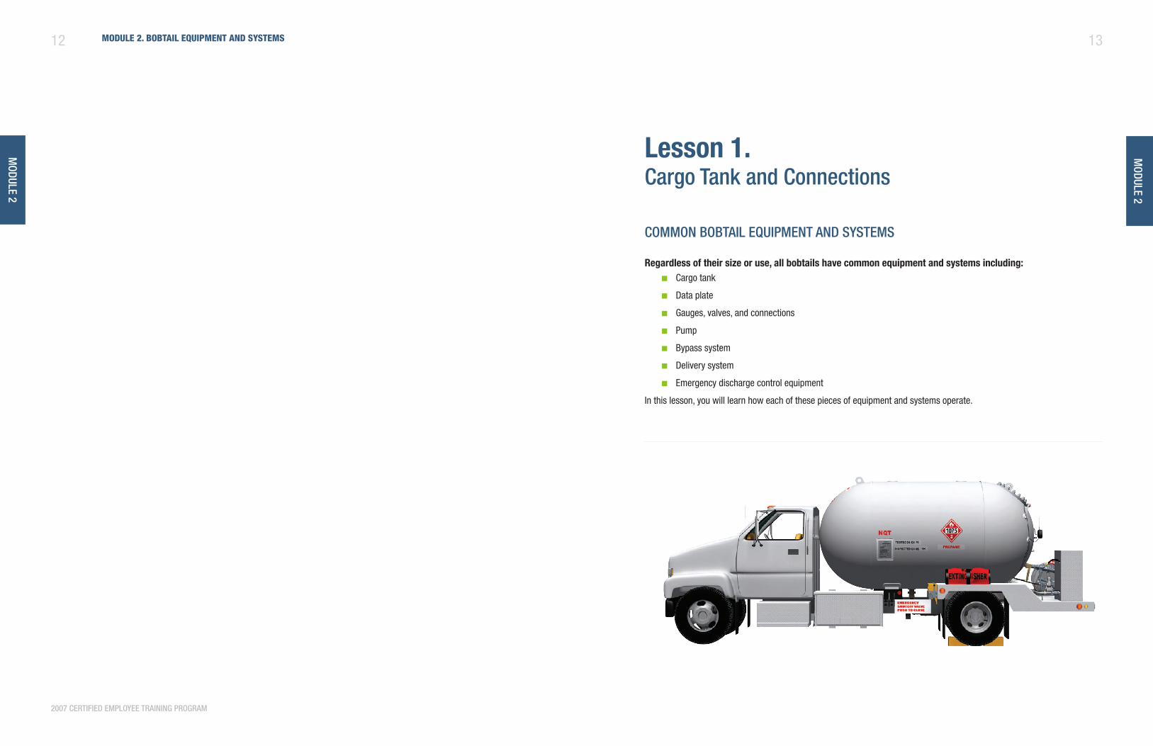
common BoBtail eQuipment and SyStemS
Regardless of their size or use, all bobtails have common equipment and systems including:Cargo tank ■
Data plate ■
Gauges, valves, and connections ■
Pump ■
Bypass system ■
Delivery system ■
Emergency discharge control equipment ■
In this lesson, you will learn how each of these pieces of equipment and systems operate.
14 Module 2. BoBtail equipMent and systeMs
2007 certified employee training program
module 2
15lesson 1. cargo tank and connections
2007 certified employee training program
module 2
different BoBtail eQuipment and SyStemS
Bobtails are specialized bulk delivery vehicles and are custom built by DOT registered manufacturers. Built in a variety of sizes, bobtails may contain different equipment and systems depending on when they were built and how they will be used.
Some examples of different bobtail features and equipment include, but are not limited to:
Chassis and cargo tank size ■
Valves and their operations ■
Gauges and their operations ■
Location of connections ■
Emergency discharge control equipment ■
Liquid meter ■
Your bobtail may also contain other features or equipment. Because bobtails vary, it is important for you to understand their differences and be prepared to use different operating procedures for each vehicle.
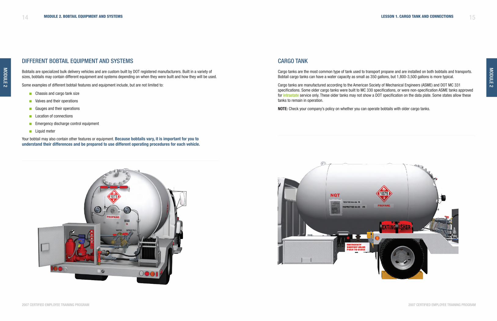
cargo tank
Cargo tanks are the most common type of tank used to transport propane and are installed on both bobtails and transports. Bobtail cargo tanks can have a water capacity as small as 350 gallons, but 1,800-3,500 gallons is more typical.
Cargo tanks are manufactured according to the American Society of Mechanical Engineers (ASME) and DOT MC 331 specifications. Some older cargo tanks were built to MC 330 specifications, or were non-specification ASME tanks approved for intrastate service only. These older tanks may not show a DOT specification on the data plate. Some states allow these tanks to remain in operation.
nOTE: Check your company’s policy on whether you can operate bobtails with older cargo tanks.
module 2
16 Module 2. BoBtail equipMent and systeMs
2007 certified employee training program
17lesson 1. cargo tank and connections
2007 certified employee training program
module 2
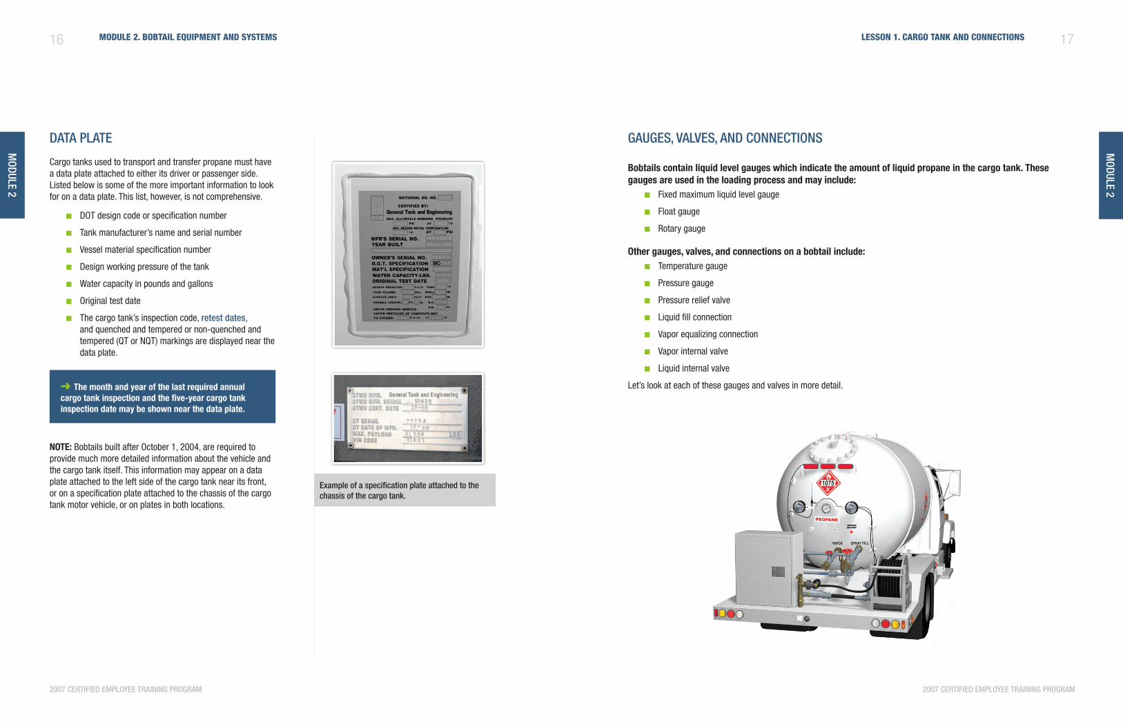
data plate
Cargo tanks used to transport and transfer propane must have a data plate attached to either its driver or passenger side. Listed below is some of the more important information to look for on a data plate. This list, however, is not comprehensive.
DOT design code or specification number ■
Tank manufacturer’s name and serial number ■
Vessel material specification number ■
Design working pressure of the tank ■
Water capacity in pounds and gallons ■
Original test date ■
The cargo tank’s inspection code, ■ retest dates, and quenched and tempered or non-quenched and tempered (QT or NQT) markings are displayed near the data plate.
➜ The month and year of the last required annual cargo tank inspection and the five-year cargo tank inspection date may be shown near the data plate.
nOTE: Bobtails built after October 1, 2004, are required to provide much more detailed information about the vehicle and the cargo tank itself. This information may appear on a data plate attached to the left side of the cargo tank near its front, or on a specification plate attached to the chassis of the cargo tank motor vehicle, or on plates in both locations.
gaugeS, valveS, and connectionS
Bobtails contain liquid level gauges which indicate the amount of liquid propane in the cargo tank. These gauges are used in the loading process and may include:
Fixed maximum liquid level gauge ■
Float gauge ■
Rotary gauge ■
Other gauges, valves, and connections on a bobtail include:Temperature gauge ■
Pressure gauge ■
Pressure relief valve ■
Liquid fill connection ■
Vapor equalizing connection ■
Vapor internal valve ■
Liquid internal valve ■
Let’s look at each of these gauges and valves in more detail.
example of a specification plate attached to the chassis of the cargo tank.
module 2
18 Module 2. BoBtail equipMent and systeMs
2007 certified employee training program
19lesson 1. cargo tank and connections
module 2
2007 certified employee training program
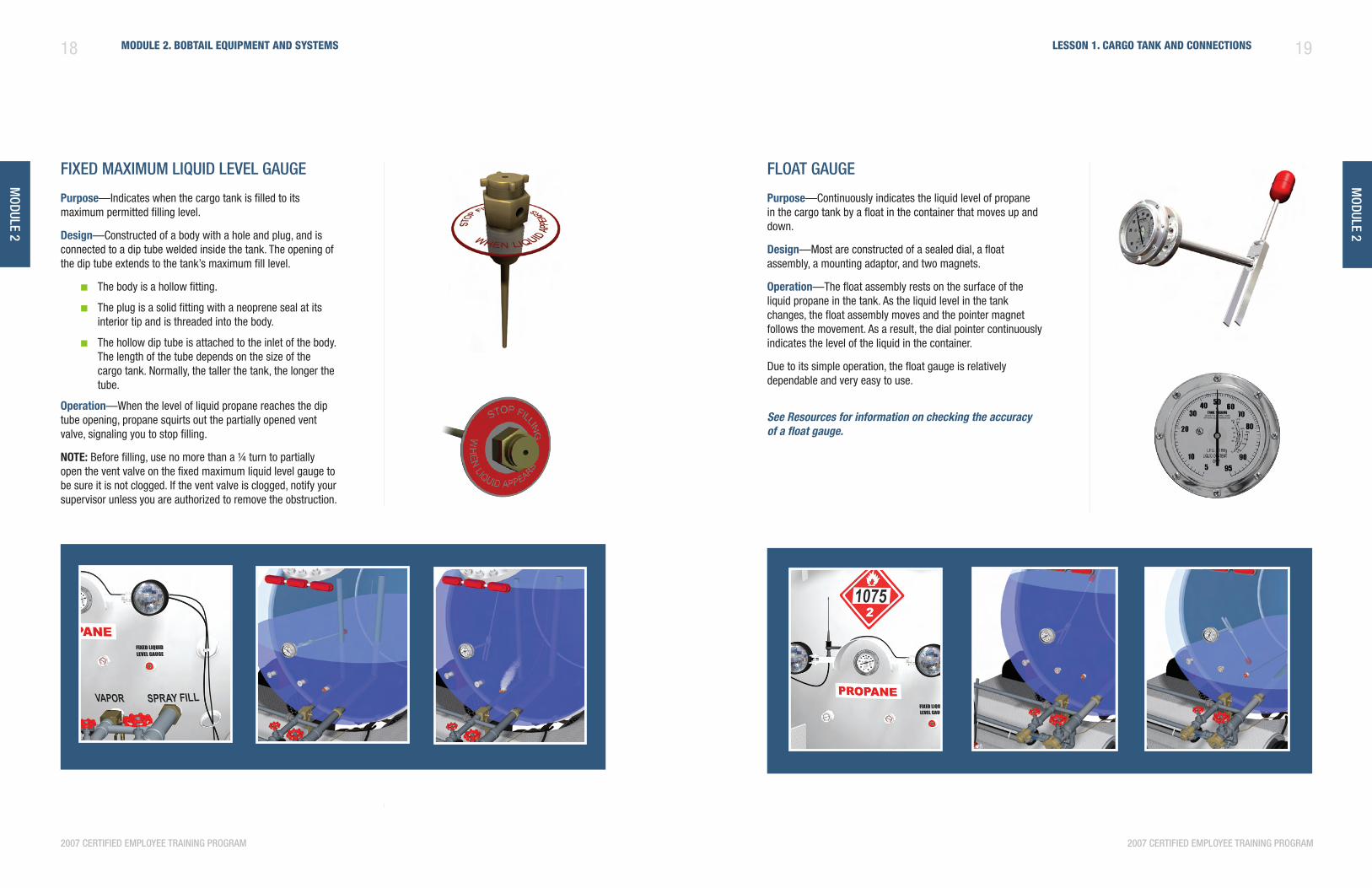
fixed maximum liQuid level gauge
Purpose—Indicates when the cargo tank is filled to its maximum permitted filling level.
Design—Constructed of a body with a hole and plug, and is connected to a dip tube welded inside the tank. The opening of the dip tube extends to the tank’s maximum fill level.
The body is a hollow fitting. ■
The plug is a solid fitting with a neoprene seal at its ■
interior tip and is threaded into the body.
The hollow dip tube is attached to the inlet of the body. ■
The length of the tube depends on the size of the cargo tank. Normally, the taller the tank, the longer the tube.
Operation—When the level of liquid propane reaches the dip tube opening, propane squirts out the partially opened vent valve, signaling you to stop filling.
nOTE: Before filling, use no more than a ¼ turn to partially open the vent valve on the fixed maximum liquid level gauge to be sure it is not clogged. If the vent valve is clogged, notify your supervisor unless you are authorized to remove the obstruction.
float gauge
Purpose—Continuously indicates the liquid level of propane in the cargo tank by a float in the container that moves up and down.
Design—Most are constructed of a sealed dial, a float assembly, a mounting adaptor, and two magnets.
Operation—The float assembly rests on the surface of the liquid propane in the tank. As the liquid level in the tank changes, the float assembly moves and the pointer magnet follows the movement. As a result, the dial pointer continuously indicates the level of the liquid in the container.
Due to its simple operation, the float gauge is relatively dependable and very easy to use.
See Resources for information on checking the accuracy of a float gauge.
module 2
20 Module 2. BoBtail equipMent and systeMs
2007 certified employee training program
21lesson 1. cargo tank and connections
2007 certified employee training program
module 2
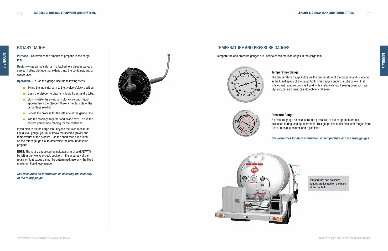
rotary gauge
Purpose—Determines the amount of propane in the cargo tank.
Design—Has an indicator arm attached to a bleeder valve; a curved, hollow dip tube that extends into the container; and a gauge face.
Operation—To use this gauge, use the following steps:
Swing the indicator arm to the twelve o’clock position. ■
Open the bleeder to clear any liquid from the dip tube. ■
Slowly rotate the swing arm clockwise until liquid ■
appears from the bleeder. Make a mental note of the percentage reading.
Repeat the process for the left side of the gauge face. ■
Add the readings together and divide by 2. This is the ■
correct percentage reading for the container.
If you plan to fill the cargo tank beyond the fixed maximum liquid level gauge, you must know the specific gravity and temperature of the product. Use the chart that is included on the rotary gauge dial to determine the amount of liquid propane.
nOTE: The rotary gauge swing indicator arm should ALWAYS be left in the twelve o’clock position. If the accuracy of the rotary or float gauge cannot be determined, use only the fixed maximum liquid level gauge.
See Resources for information on checking the accuracy of the rotary gauge.
temperature and preSSure gaugeS
Temperature and pressure gauges are used to check the load of gas in the cargo tank.
Temperature gaugeThe temperature gauge indicates the temperature of the propane and is located in the liquid space of the cargo tank. This gauge contains a tube or well that is filled with a non-corrosive liquid with a relatively low freezing point such as glycerin, oil, kerosene, or automobile antifreeze.
Pressure gaugeA pressure gauge helps ensure that pressures in the cargo tank are not exceeded during loading operations. This gauge has a dial face with ranges from 0 to 400 psig, a pointer, and a gas inlet.
See Resources for more information on temperature and pressure gauges.
temperature and pressure gauges are located on the back of the bobtail.
22 Module 2. BoBtail equipMent and systeMs
2007 certified employee training program
module 2
23lesson 1. cargo tank and connections
module 2
2007 certified employee training program
tHe importance of underStanding cargo tank gaugeS
When filling your bobtail or your customer’s container, it is critical that you understand each individual gauge’s function and how they work together to ensure a safe product transfer. Your ability to read, monitor, and understand how gauges indicate the level of the liquid in the container is a key skill that bobtail drivers must master.
Understanding exactly how the gauges are supposed to function will also help you respond appropriately if a gauge malfunctions or its reading is in conflict with another gauge.
here are a few issues to consider as you learn more about gauges and their importance in an overall successful product transfer:
Bobtail gauges help measure maximum-permitted filling capacity. ■
Fixed maximum liquid level gauges and rotary gauges are designed to emit product when the cargo tank reaches 80 ■
to 85% of its maximum-permitted filling capacity.
If a liquid level gauge shows an increase in product, then the cargo tank’s pressure gauge should show an increase ■
in pressure at the same time.
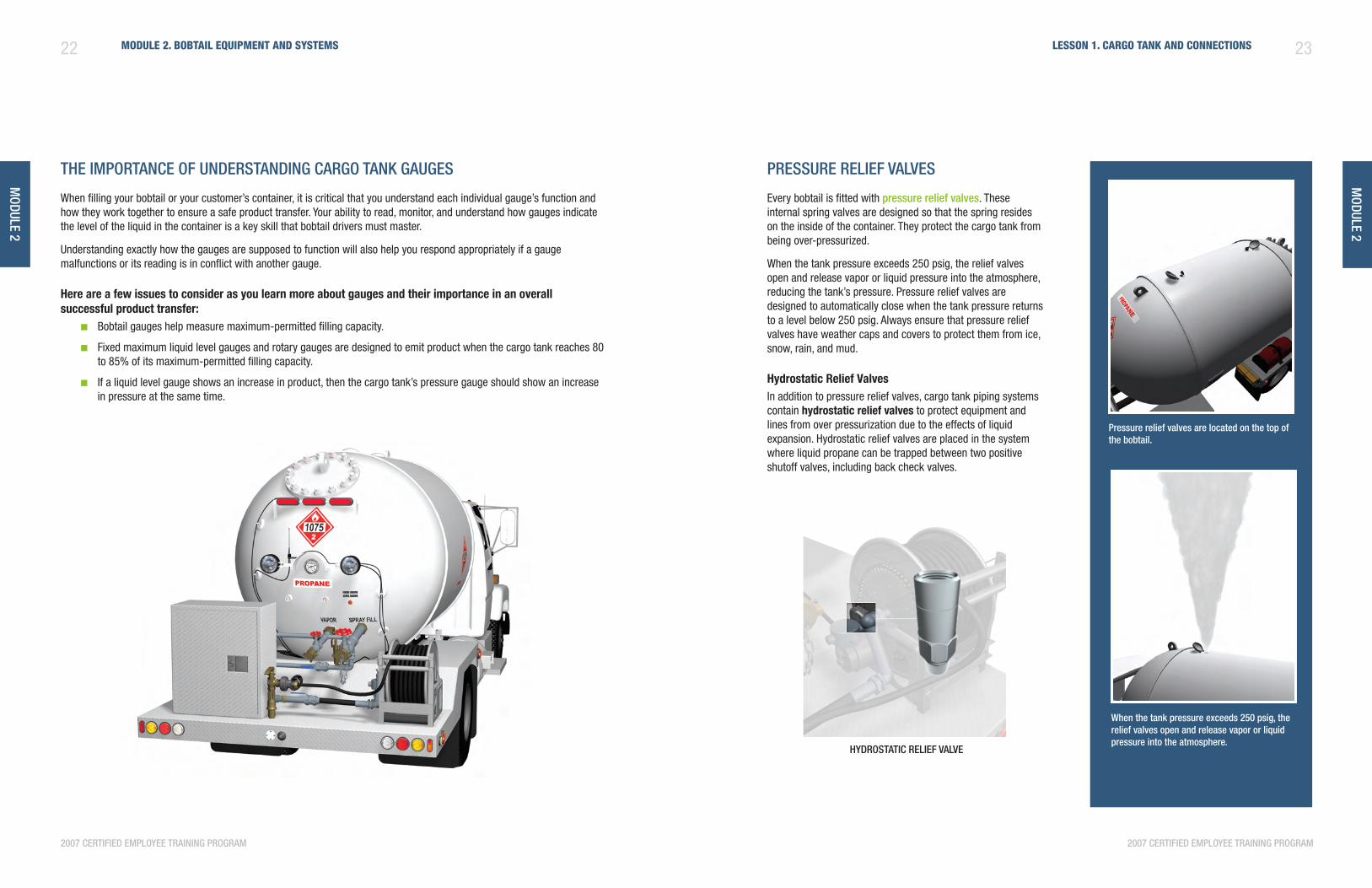
preSSure relief valveS
Every bobtail is fitted with pressure relief valves. These internal spring valves are designed so that the spring resides on the inside of the container. They protect the cargo tank from being over-pressurized.
When the tank pressure exceeds 250 psig, the relief valves open and release vapor or liquid pressure into the atmosphere, reducing the tank’s pressure. Pressure relief valves are designed to automatically close when the tank pressure returns to a level below 250 psig. Always ensure that pressure relief valves have weather caps and covers to protect them from ice, snow, rain, and mud.
hydrostatic Relief valvesIn addition to pressure relief valves, cargo tank piping systems contain hydrostatic relief valves to protect equipment and lines from over pressurization due to the effects of liquid expansion. Hydrostatic relief valves are placed in the system where liquid propane can be trapped between two positive shutoff valves, including back check valves.
HydroStatic relief valve
pressure relief valves are located on the top of the bobtail.
When the tank pressure exceeds 250 psig, the relief valves open and release vapor or liquid pressure into the atmosphere.
module 2
24 Module 2. BoBtail equipMent and systeMs
2007 certified employee training program
25lesson 1. cargo tank and connections
module 2
2007 certified employee training program
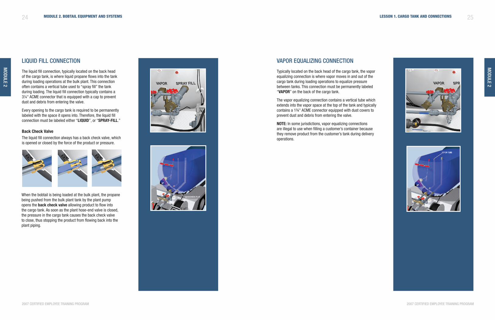
liQuid fill connection
The liquid fill connection, typically located on the back head of the cargo tank, is where liquid propane flows into the tank during loading operations at the bulk plant. This connection often contains a vertical tube used to “spray fill” the tank during loading. The liquid fill connection typically contains a 3¼" ACME connector that is equipped with a cap to prevent dust and debris from entering the valve.
Every opening to the cargo tank is required to be permanently labeled with the space it opens into. Therefore, the liquid fill connection must be labeled either “lIquID”, or “sPRay-fIll.”
Back Check valveThe liquid fill connection always has a back check valve, which is opened or closed by the force of the product or pressure.
vapor eQualizing connection
Typically located on the back head of the cargo tank, the vapor equalizing connection is where vapor moves in and out of the cargo tank during loading operations to equalize pressure between tanks. This connection must be permanently labeled “vaPOR” on the back of the cargo tank.
The vapor equalizing connection contains a vertical tube which extends into the vapor space at the top of the tank and typically contains a 1¾" ACME connector equipped with dust covers to prevent dust and debris from entering the valve.
nOTE: In some jurisdictions, vapor equalizing connections are illegal to use when filling a customer’s container because they remove product from the customer’s tank during delivery operations.
When the bobtail is being loaded at the bulk plant, the propane being pushed from the bulk plant tank by the plant pump opens the back check valve allowing product to flow into the cargo tank. As soon as the plant hose-end valve is closed, the pressure in the cargo tank causes the back check valve to close, thus stopping the product from flowing back into the plant piping.
module 2
26 Module 2. BoBtail equipMent and systeMs
2007 certified employee training program
27lesson 1. cargo tank and connections
2007 certified employee training program
module 2
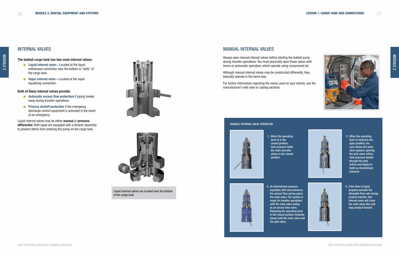
internal valveS
The bobtail cargo tank has two main internal valves:liquid internal valve ■ —Located at the liquid withdrawal connection near the bottom or “belly” of the cargo tank.
vapor internal valve ■ —Located at the vapor equalizing connection.
Both of these internal valves provide:automatic excess flow protection ■ if piping breaks away during transfer operations.
Primary shutoff protection ■ if the emergency discharge control equipment is activated in the event of an emergency.
Liquid internal valves may be either manual or pressure differential. Both types are equipped with a strainer assembly to prevent debris from entering the pump on the cargo tank.
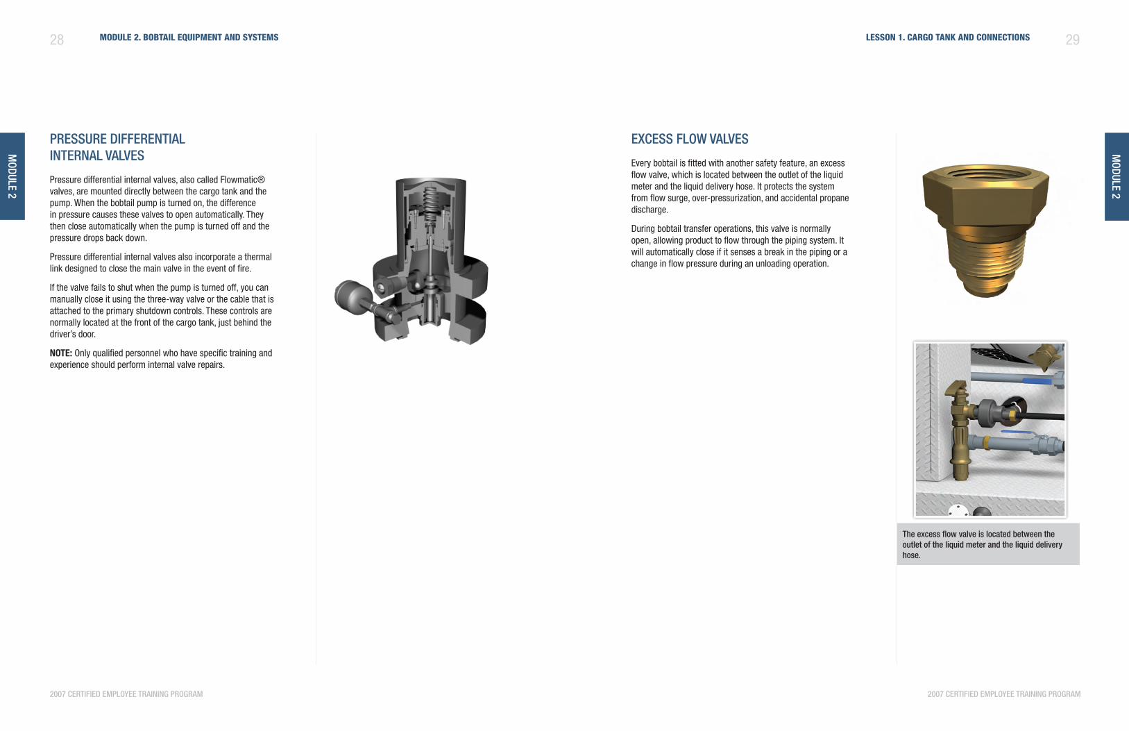
manual internal valveS
Always open manual internal valves before starting the bobtail pump during transfer operations. You must physically open these valves with levers or pneumatic operators, which operate using compressed air.
Although manual internal valves may be constructed differently, they basically operate in the same way.
For further information regarding the valves used on your vehicle, see the manufacturer’s web sites or catalog sections.
manual internal valve operation
When the operating 2. lever is moved to the open position, the cam moves the valve stem upward, opening the pilot valve orifice. tank pressure bleeds through the pilot orifice and begins to build up downstream pressure.
as downstream pressure 3. equalizes with tank pressure, the excess flow spring opens the main valve. the system is ready for transfer operations with the main valve acting as an excess flow valve. releasing the operating lever to the closed position instantly closes both the main valve and the pilot valve.
if the flow of liquid 4. propane exceeds the allowable flow rate during product transfer, this internal valve will close the main valve disc and stop product transfer.
When the operating 1. lever is in the closed position, tank pressure holds the main and pilot valves in the closed position.
liquid internal valves are located near the bottom of the cargo tank.
module 2
28 Module 2. BoBtail equipMent and systeMs
2007 certified employee training program
29lesson 1. cargo tank and connections
module 2
2007 certified employee training program
preSSure differential internal valveS
Pressure differential internal valves, also called Flowmatic® valves, are mounted directly between the cargo tank and the pump. When the bobtail pump is turned on, the difference in pressure causes these valves to open automatically. They then close automatically when the pump is turned off and the pressure drops back down.
Pressure differential internal valves also incorporate a thermal link designed to close the main valve in the event of fire.
If the valve fails to shut when the pump is turned off, you can manually close it using the three-way valve or the cable that is attached to the primary shutdown controls. These controls are normally located at the front of the cargo tank, just behind the driver’s door.
nOTE: Only qualified personnel who have specific training and experience should perform internal valve repairs.
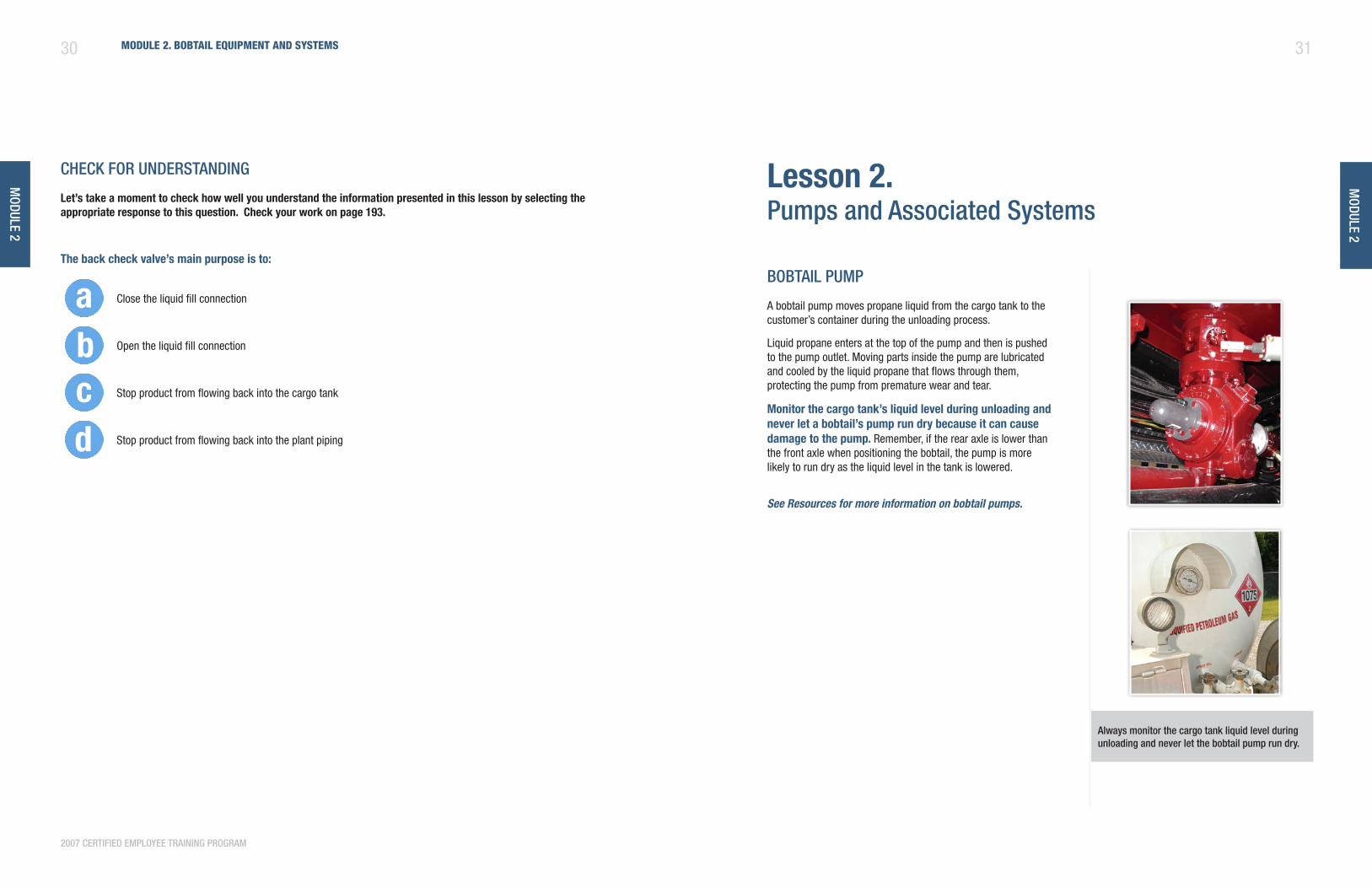
exceSS floW valveS
Every bobtail is fitted with another safety feature, an excess flow valve, which is located between the outlet of the liquid meter and the liquid delivery hose. It protects the system from flow surge, over-pressurization, and accidental propane discharge.
During bobtail transfer operations, this valve is normally open, allowing product to flow through the piping system. It will automatically close if it senses a break in the piping or a change in flow pressure during an unloading operation.
the excess flow valve is located between the outlet of the liquid meter and the liquid delivery hose.
30 Module 2. BoBtail equipMent and systeMs
2007 certified employee training program
module 2
31
module 2
cHeck for underStanding
let’s take a moment to check how well you understand the information presented in this lesson by selecting the appropriate response to this question. Check your work on page 193.
The back check valve’s main purpose is to:
Close the liquid fill connection
Open the liquid fill connection
Stop product from flowing back into the cargo tank
Stop product from flowing back into the plant piping
lesson 2. pumps and associated Systems
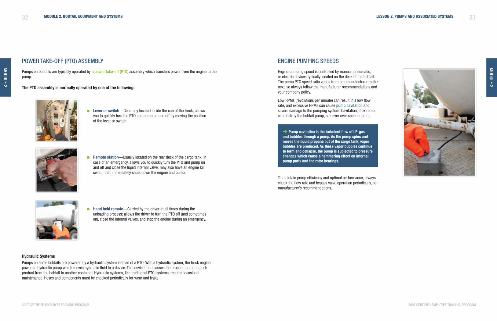
BoBtail pump
A bobtail pump moves propane liquid from the cargo tank to the customer’s container during the unloading process.
Liquid propane enters at the top of the pump and then is pushed to the pump outlet. Moving parts inside the pump are lubricated and cooled by the liquid propane that flows through them, protecting the pump from premature wear and tear.
Monitor the cargo tank’s liquid level during unloading and never let a bobtail’s pump run dry because it can cause damage to the pump. Remember, if the rear axle is lower than the front axle when positioning the bobtail, the pump is more likely to run dry as the liquid level in the tank is lowered.
See Resources for more information on bobtail pumps.
always monitor the cargo tank liquid level during unloading and never let the bobtail pump run dry.
32 Module 2. BoBtail equipMent and systeMs
2007 certified employee training program
module 2
33lesson 2. puMps and associated systeMs
module 2
2007 certified employee training program
poWer take-off (pto) aSSemBly
Pumps on bobtails are typically operated by a power take-off (pto) assembly which transfers power from the engine to the pump.
The PTO assembly is normally operated by one of the following:
engine pumping SpeedS
Engine pumping speed is controlled by manual, pneumatic, or electric devices typically located on the deck of the bobtail. The pump PTO speed ratio varies from one manufacturer to the next, so always follow the manufacturer recommendations and your company policy.
Low RPMs (revolutions per minute) can result in a low flow rate, and excessive RPMs can cause pump cavitation and severe damage to the pumping system. Cavitation, if extreme, can destroy the bobtail pump, so never over speed a pump.
➜ Pump cavitation is the turbulent flow of lP-gas and bubbles through a pump. as the pump spins and moves the liquid propane out of the cargo tank, vapor bubbles are produced. as these vapor bubbles continue to form and collapse, the pump is subjected to pressure changes which cause a hammering effect on internal pump parts and the rotor bearings.
To maintain pump efficiency and optimal performance, always check the flow rate and bypass valve operation periodically, per manufacturer’s recommendations.
lever or switch ■ —Generally located inside the cab of the truck; allows you to quickly turn the PTO and pump on and off by moving the position of the lever or switch.
Remote station ■ —Usually located on the rear deck of the cargo tank; in case of an emergency, allows you to quickly turn the PTO and pump on and off and close the liquid internal valve; may also have an engine kill switch that immediately shuts down the engine and pump.
hand held remote ■ —Carried by the driver at all times during the unloading process; allows the driver to turn the PTO off (and sometimes on), close the internal valves, and stop the engine during an emergency.
hydraulic systemsPumps on some bobtails are powered by a hydraulic system instead of a PTO. With a hydraulic system, the truck engine powers a hydraulic pump which moves hydraulic fluid to a device. This device then causes the propane pump to push product from the bobtail to another container. Hydraulic systems, like traditional PTO systems, require occasional maintenance. Hoses and components must be checked periodically for wear and leaks.
module 2
34 Module 2. BoBtail equipMent and systeMs
2007 certified employee training program
35lesson 2. puMps and associated systeMs
2007 certified employee training program
module 2
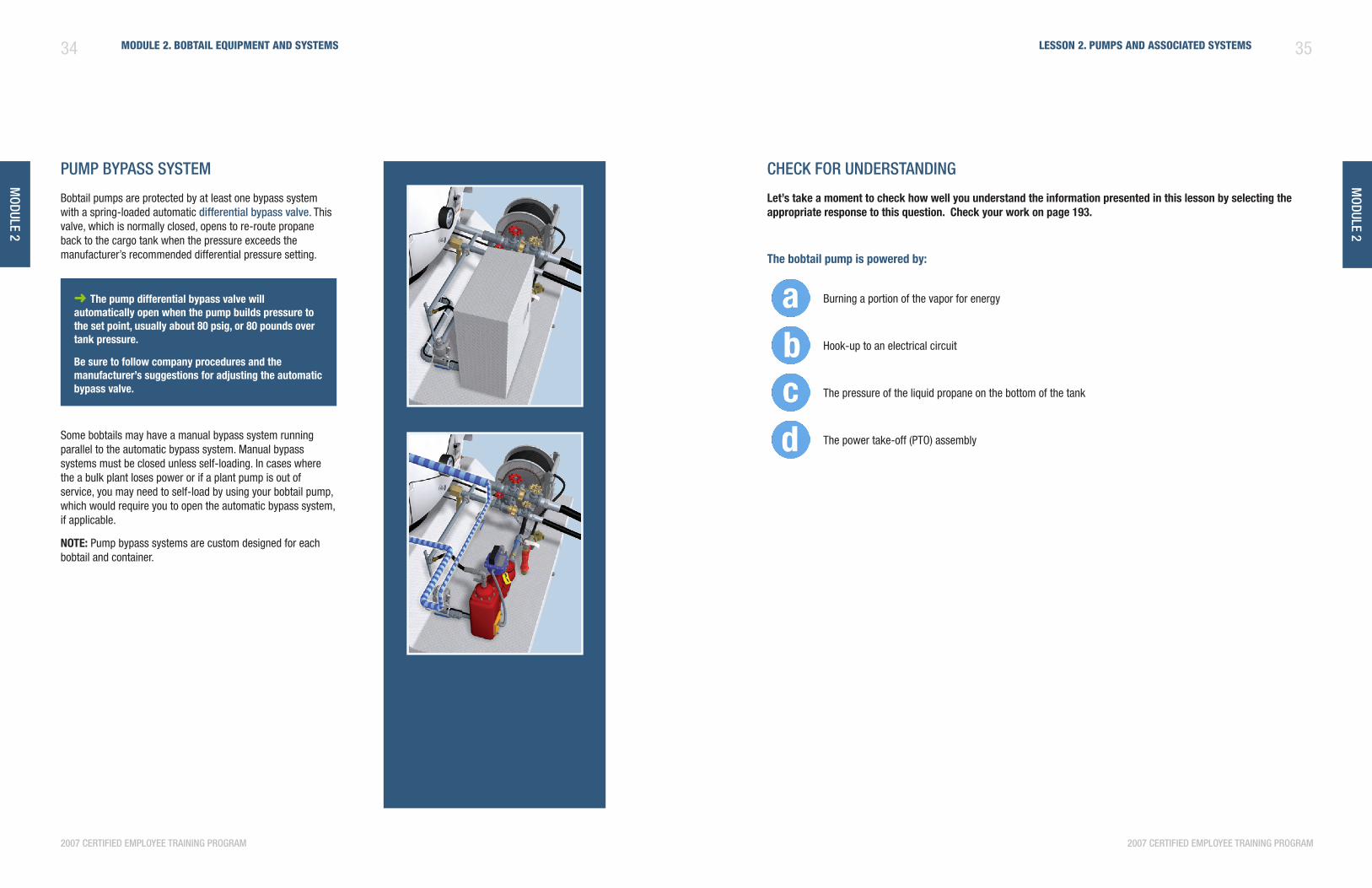
pump BypaSS SyStem
Bobtail pumps are protected by at least one bypass system with a spring-loaded automatic differential bypass valve. This valve, which is normally closed, opens to re-route propane back to the cargo tank when the pressure exceeds the manufacturer’s recommended differential pressure setting.
➜ The pump differential bypass valve will automatically open when the pump builds pressure to the set point, usually about 80 psig, or 80 pounds over tank pressure.
Be sure to follow company procedures and the manufacturer’s suggestions for adjusting the automatic bypass valve.
Some bobtails may have a manual bypass system running parallel to the automatic bypass system. Manual bypass systems must be closed unless self-loading. In cases where the a bulk plant loses power or if a plant pump is out of service, you may need to self-load by using your bobtail pump, which would require you to open the automatic bypass system, if applicable.
nOTE: Pump bypass systems are custom designed for each bobtail and container.
cHeck for underStanding
let’s take a moment to check how well you understand the information presented in this lesson by selecting the appropriate response to this question. Check your work on page 193.
The bobtail pump is powered by:
Burning a portion of the vapor for energy
Hook-up to an electrical circuit
The pressure of the liquid propane on the bottom of the tank
The power take-off (PTO) assembly
37
module 2
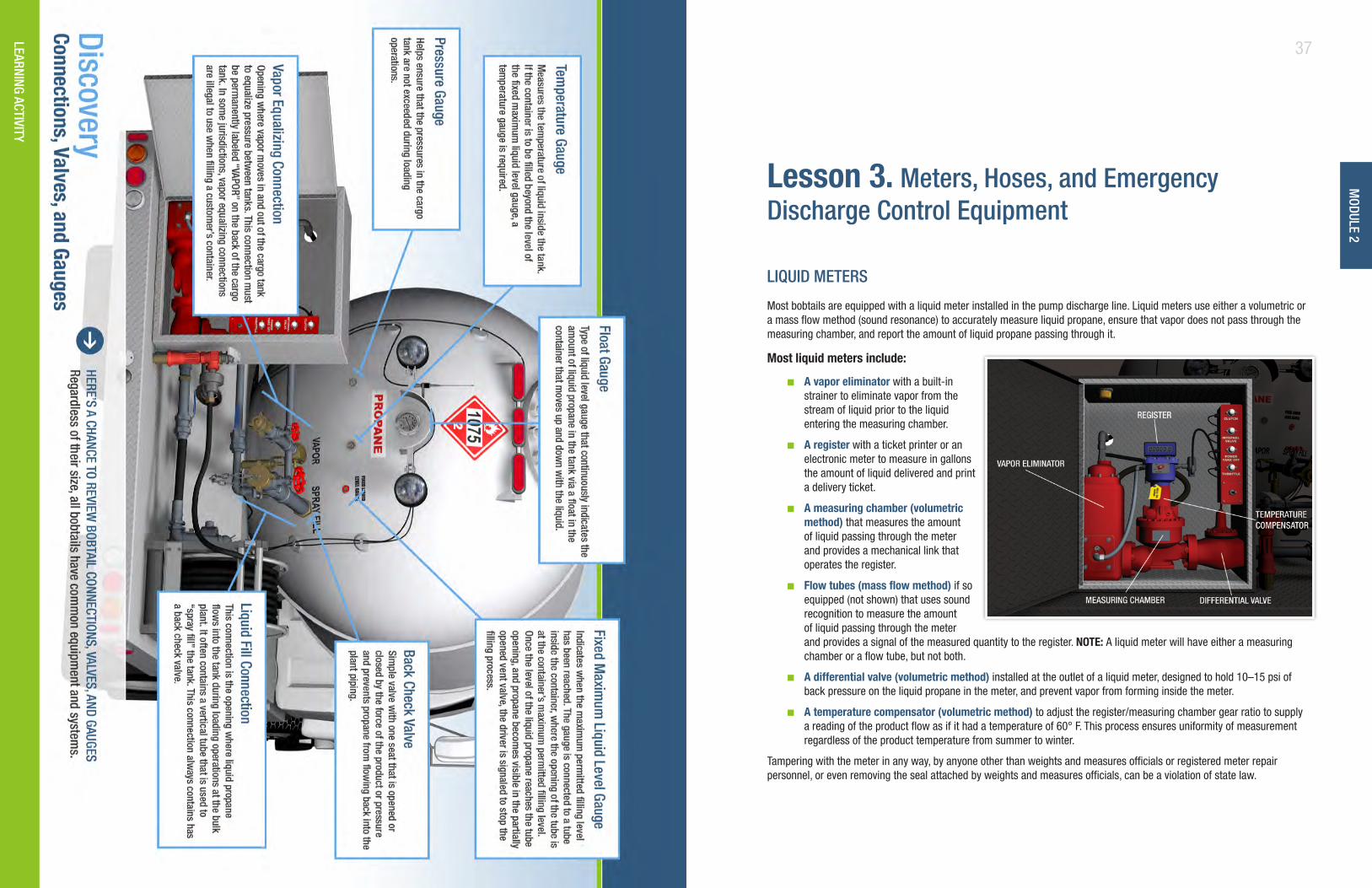
discovery: connections, valves, and gauges
lesson 3. meters, Hoses, and emergency discharge control equipment
liQuid meterS
Most bobtails are equipped with a liquid meter installed in the pump discharge line. Liquid meters use either a volumetric or a mass flow method (sound resonance) to accurately measure liquid propane, ensure that vapor does not pass through the measuring chamber, and report the amount of liquid propane passing through it.
Most liquid meters include:
a vapor eliminator ■ with a built-in strainer to eliminate vapor from the stream of liquid prior to the liquid entering the measuring chamber.
a register ■ with a ticket printer or an electronic meter to measure in gallons the amount of liquid delivered and print a delivery ticket.
a measuring chamber (volumetric ■
method) that measures the amount of liquid passing through the meter and provides a mechanical link that operates the register.
flow tubes (mass flow method) ■ if so equipped (not shown) that uses sound recognition to measure the amount of liquid passing through the meter and provides a signal of the measured quantity to the register. nOTE: A liquid meter will have either a measuring chamber or a flow tube, but not both.
a differential valve (volumetric method) ■ installed at the outlet of a liquid meter, designed to hold 10–15 psi of back pressure on the liquid propane in the meter, and prevent vapor from forming inside the meter.
a temperature compensator (volumetric method) ■ to adjust the register/measuring chamber gear ratio to supply a reading of the product flow as if it had a temperature of 60° F. This process ensures uniformity of measurement regardless of the product temperature from summer to winter.
Tampering with the meter in any way, by anyone other than weights and measures officials or registered meter repair personnel, or even removing the seal attached by weights and measures officials, can be a violation of state law.
learning activity
module 2
38 Module 2. BoBtail equipMent and systeMs
2007 certified employee training program
39lesson 3. Meters, Hoses, and eMergency discHarge control equipMent
2007 certified employee training program
module 2
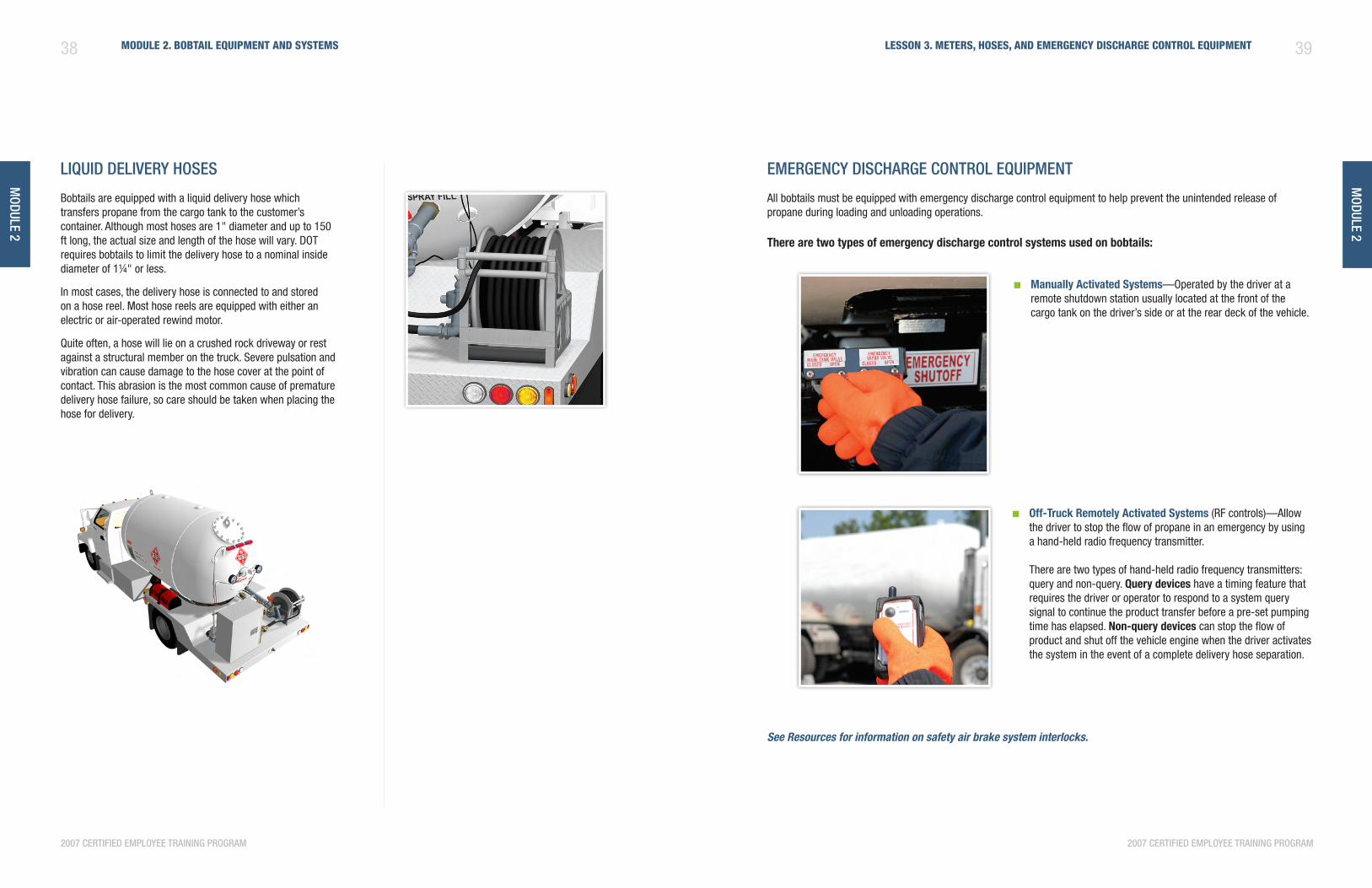
liQuid delivery HoSeS
Bobtails are equipped with a liquid delivery hose which transfers propane from the cargo tank to the customer’s container. Although most hoses are 1" diameter and up to 150 ft long, the actual size and length of the hose will vary. DOT requires bobtails to limit the delivery hose to a nominal inside diameter of 1¼" or less.
In most cases, the delivery hose is connected to and stored on a hose reel. Most hose reels are equipped with either an electric or air-operated rewind motor.
Quite often, a hose will lie on a crushed rock driveway or rest against a structural member on the truck. Severe pulsation and vibration can cause damage to the hose cover at the point of contact. This abrasion is the most common cause of premature delivery hose failure, so care should be taken when placing the hose for delivery.
emergency diScHarge control eQuipment
All bobtails must be equipped with emergency discharge control equipment to help prevent the unintended release of propane during loading and unloading operations.
There are two types of emergency discharge control systems used on bobtails:
Manually activated systems ■ —Operated by the driver at a remote shutdown station usually located at the front of the cargo tank on the driver’s side or at the rear deck of the vehicle.
Off-Truck Remotely activated systems ■ (RF controls)—Allow the driver to stop the flow of propane in an emergency by using a hand-held radio frequency transmitter. There are two types of hand-held radio frequency transmitters: query and non-query. query devices have a timing feature that requires the driver or operator to respond to a system query signal to continue the product transfer before a pre-set pumping time has elapsed. non-query devices can stop the flow of product and shut off the vehicle engine when the driver activates the system in the event of a complete delivery hose separation.
See Resources for information on safety air brake system interlocks.
40 Module 2. BoBtail equipMent and systeMs
2007 certified employee training program
module 2
41lesson 3. Meters, Hoses, and eMergency discHarge control equipMent
2007 certified employee training program
module 2
cHeck for underStanding
let’s take a moment to check how well you understand the information presented in this lesson by selecting the appropriate response to this question. Check your work on page 193.
One reliable way to ensure that the liquid delivery hose does not become damaged is to _____.
Purchase hose that has a nominal inside diameter of 2¼" or more
Ensure that the hose does not rest against items that may cause wear during the loading operation
Load your bobtail when the weather conditions are favorable
Cover the hose during loading operations
Summary
some important points to remember from this module are:
Bobtails can be different sizes and have different equipment. However, all bobtails have a cargo tank and ■
connections, a pump and associated systems, liquid meter, hoses, and emergency discharge control equipment.
The typical bobtail has a cargo tank that ranges between 1,800 and 3,500 gallons water capacity. ■
Bobtails contain liquid level gauges used in the loading process to indicate the amount of liquid propane in the cargo ■
tank.
DOT requires that all bobtails have internal valves to prevent a massive release of product in an emergency. ■
Most bobtails are equipped with a liquid meter installed in the pump discharge line to calculate the correct number ■
of gallons delivered.
All bobtails must be equipped with emergency discharge control equipment to help prevent the unintended release ■
of propane during unloading operations.