Embed Size (px)
Citation preview
Copyright is owned by Constructive Details Ltd.Copying or reproduction of the contents is not permitted without the consent of Constructive Details Ltd.
Constructive Details Ltd
Bucknalls Lane,WatfordHertfordshire WD25 9BA
t: + 44 (0)1923 665300f: + 44 (0)1923 665301
e: [email protected] w: www.constructivedetails.co.uk ©2012
A Handbook of thermal bridging details incorporating aircrete blocks
Book 1 — Thermal bridging solutions for external wall partial fill cavity details and full fill party wall
details Prepared for the Aircrete Products Association
by the BBA and RDL
Issued: 1 June 2012Page 1

Table of Contents
List of Constructive Details 3
How to use this handbook 4
Front page — Illustration 4
Main body — �-values 4
Last page — Checklist 5
Acoustic performance 5
Example using CD0002 6
Partial fill cavity wall 8 CD0001 — CD0016
Full fill party wall 59 CD0017 — CD0021
This handbook was prepared for the Aircrete Products Association (APA can be contacted at www.aircrete.co.uk) and it aims to provide a set of thermal bridging junction details for a new dwelling. The details are for a masonry external wall with a partial fill cavity wall insulation, constructed using aircrete blocks. The drawings provided are for typical details and show all the elements essential in achieving the calculated �-values. All other site requirements and all relevant building regulations must be taken into consideration when implementing the details.
Each detail in this handbook includes drawings of the junction, �-values calculated by an experienced thermal modeller and a process checklist for use on site to facilitate the achievement of the calculated �-values.
Purpose of the handbookPurpose of the handbook
Page 2

There are a total of 21 details, labelled CD0001 to CD0021. To provide additional guidance for designers and specifiers the corresponding E and P numbers given in the SAP conventions document are also included.
The Handbook covers aircrete blocks for three different conductivity values up to 0.11 W·m–1·K–1, 0.15 W·m–1·K–1 and 0.19 W·m–1·K–1. Other APA blocks with intermediate thermal conductivity values or lower than 0.11 (for example 0.09 W·m–1·K–1) could also be used without significantly affecting the �-values provided. For example, if using blocks with a � value of 0.18 W·m–1·K–1, the 0.19 W·m–1·K–1 values can be taken and would, in the vast majority of cases represent the worst case scenario solution. A number of such aircrete blocks are covered by BBA Certification (see www.bbacerts.co.uk) and only aircrete blocks manufactured by the APA may be used. When aircrete blocks were used in the ground, the thermal conductivity has been adjusted for higher moisture content.
This handbook begins with the ground floor junctions, moving on to lintels and windows, intermediate floor and roof, corner and a party wall with an external wall, and concludes with floor and roof junctions with a fully filled party wall. These junctions are for separating walls between dwellings and the �-values should be applied to each dwelling.
Detail number Detail title SAP ref
CD0001 External Masonry Cavity Wall. Partial Fill Suspended beam-and-block floor — Insulation above slab E5
CD0002 External Masonry Cavity Wall. Partial Fill Suspended in-situ concrete floor — Insulation below slab E5
CD0003 External Masonry Cavity Wall. Partial Fill Concrete ground bearing floor — Insulation below slab E5
CD0004 External Masonry Cavity Wall. Partial Fill Independent lintel E2
CD0005 External Masonry Cavity Wall. Partial Fill Steel lintel — Perforated base plate (Insulated soffit) E1
CD0006 External Masonry Cavity Wall. Partial Fill Sill E3
CD0007 External Masonry Cavity Wall. Partial Fill Jamb E4
CD0008 External Masonry Cavity Wall. Partial Fill Intermediate timber floor within a dwelling E6
CD0009 External Masonry Cavity Wall. Partial Fill Precast concrete separating floor between dwellings E7
CD0010 External Masonry Cavity Wall. Partial Fill Pitched roof. Gable — Insulation at ceiling level — Ventilated loft E12
CD0011 External Masonry Cavity Wall. Partial FillPitched roof. Gable — Insulation at rafter Level — Unventilated rafter void E13
CD0012 External Masonry Cavity Wall. Partial Fill Pitched roof. Eaves — Insulation at ceiling level — Ventilated Loft E10
CD0013 External Masonry Cavity Wall. Partial Fill Pitched roof. Eaves — Insulation at rafter level — Unventilated rafter void E11
CD0014 External Masonry Cavity Wall. Partial Fill Normal corner E16
CD0015 External Masonry Cavity Wall. Partial Fill Inverted corner E17
CD0016 External Masonry Cavity Wall. Partial Fill Party wall between dwellings E18
CD0017 Party Wall Masonry. Full Fill Suspended beam-and-block floor — Insulation above slab P1
CD0018 Party Wall Masonry. Full Fill Suspended concrete floor — Insulation below slab P1
CD0019 Party Wall Masonry. Full Fill In-situ concrete ground bearing floor — Insulation below slab P1
CD0020 Party Wall Masonry. Full Fill Roof — Insulation at ceiling level — Ventilated loft P4
CD0021 Party Wall Masonry. Full Fill Roof — Insulation at rafter level — Unventilated rafter void P5
List of Constructive Details
Page 3

The details have been prepared in line with the range of U values appropriate to achieve compliance within The Building Regulations 2010 (England and Wales), Part L. Therefore all of the building elements have an upper U value limit of 0.30 W·m–2·K–1 for a wall, 0.25 W·m–2·K–1 for a floor and 0.20 W·m–2·K–1 for the roof element, inline with the limiting fabric parameters given in Approved Document L1A.
The �-values are provided for different bands of U values. For each band the �-value is calculated for the worst case after considering the effect of thickness and conductivity of insulation independently. This �-value can therefore be taken for the complete range of U values quoted.
In all of the details the wall finish drawn is plasterboard on dabs. This was chosen for consistency and also as it is a common construction method. It is not, however, essential to use this internal finish solution to achieve the stated �-value. The same applies for the use of rendered block or brick for the outer leaf. Additionally the mortar joints are indicative and may not necessarily coincide with those shown in the diagrams. The maximum external wall cavity width is 200 mm and the residual air space is kept clear. Although the details show 100 mm thick blocks, greater thicknesses up to 140 mm may also be adopted, without significantly affecting the calculated values.
As a general rule, unless a specific solution for a wall or floor finish is either indicated in the Notes section or is explicitly mentioned in the annotations, it should be considered optional. The main driver in selecting the materials for each detail would be to achieve the U value bands as provided in each detail.
Some minimum guidance on how to achieve air tightness is also provided. As a general rule, acceptable barrier options are the use of plastercoat, blockwork inner leaf/parging coat applied to the internal face of the inner leaf with plasterboard cover, or plasterboard on dabs. Where plasterboard on dabs is used, a continuous ribbon of adhesive should also be applied around all openings, along the top and bottom of the wall and at internal and external corners. In general, all penetrations through the air barrier should be sealed with a flexible sealant. This type of guidance can also be found in the current Accredited Construction Details, available at the DCLG portal.
A series of tips on interpreting the information in each Constructive Detail, is given below, starting from the first to the last page.
The drawingThe front page drawing is in full colour, and the annotations identify the critical parameters that must be observed in order for this junction to achieve the calculated �-values. The annotations are also consistent with the wording used in the Notes section, to make it easier to read and understand the important elements.
The Notes This section relates to the steps in the build process of the junction that are essential for the construction of the detail with regards to achieving the stated �-values. Any other guidance by all relevant Building Regulations must be followed and this detail focuses only on the thermal performance and provides basic guidance with regards to air tightness.
The drawing The second drawing provides additional information to that given on the front page. It highlights in colour the product for which these details have been produced, in this case, the aircrete blocks. It also indicates the position of the air barrier that must be maintained and provides the necessary information to enable the U value calculation to be carried out.
�-values A table of �-values (psi-values) and temperature factors is provided for each detail. The banding of U values provides the specifier with the flexibility to use different U values for the main elements, but ensures that the calculated �-value is still valid within that range. The �-values were calculated and checked by an experienced individual, as required by Approved Document L1A, using the THERM or TRISCO software, the latter where 3D modelling was required.
How to use this handbook
Front page — Illustration
Main body — �-values
Page 4

The temperature factor is a property of the construction and is used to assess the risk of surface condensation or mould growth. This parameter is provided in all the junctions. In all cases the calculated values are higher than the critical temperature factor for dwellings (0.75) as given in BRE Information Paper IP 1/06 Assessing the effects of thermal bridging at junctions and around openings, which limits the risk of surface condensation or mould growth.
All �-values have been calculated in accordance with BRE Report 497 : 2007 Conventions for calculating linear thermal transmittance and temperature factors and other relevant standards quoted within that document.
U value examplesSome indicative guidance on the insulation thickness and thermal conductivity values required to achieve the U value example constructions in combination with the aircrete blocks, are also provided. Depending on the complexity of the detail, there are one or more U value bands available. There is no specification for the type of insulation used, but the necessary information is provided to enable the calculations to be repeated. The U values were calculated in accordance with BRE Report (BR 443 : 2006) Conventions for U-value calculations and other relevant British Standards.
A fully detailed U value calculation using the stated thickness and thermal conductivity values may produce lower U values than that indicated in the details, as only the minimum amount of information is provided, such as the use of aircrete blocks, thickness and conductivity of insulation. Other combinations of thicknesses and conductivities can be used to achieve the U values, and as long as these are within the bands provided, the corresponding �-value will still be valid. This provides the user with considerable flexibility compared to more traditional representations of �-values, while maintaining the accuracy and technical rigour of the calculation.
Guidance checklistThis part of the detail relates to the quality assurance aspect, which used in combination with guidance given on the first page, would provide reassurance to the builder that this detail will perform as expected. The creation of the list is a combination of the thermal modelling analysis of the detail and site experience.
The Notes box is intended for the inspector or the site supervisor to record any additional information or changes that may have occurred to the final built detail. It can be used as a log of the work done for each detail and as a process for checking by the site supervisor, to ensure the detail was constructed as detailed and so that the calculated �-values can be achieved.
One more parameter that was also considered in the preparation of the details was the acoustic performance of the junctions. Where appropriate, advice was provided by RDL to establish that the details could be followed without conflicting with the acoustic requirements of that scheme. For example, the cavity widths and insulation for separating walls are specified such that they can accommodate what is required in a corresponding acoustic detail. The Robust Details (RD) Handbook must be referenced when using the RD scheme.
A similar approach was also taken for the intermediate floors details, which led to the production of two details, one for the separating floor and another for the intermediate floor detail between dwellings, which in Appendix K of SAP 2009 have the same �-values.
Last page — Checklist
Acoustic performance
Page 5

Lets assume that you are using this junction detail where the wall consists of 100 mm of aircrete blocks (� = 0.19 W·m–1·K–1) and 85 mm of foil-faced insulation with a � value of 0.022 W·m–1·K–1. If using the example construction provided, the U value of the wall will be 0.20 W·m–2·K–1, or less, which means that the corresponding �-values would be the ones given in the first line and column of the three main tables, so either 0.128 W·m–1·K–1, 0.119 W·m–1·K–1 or 0.064 W·m–1·K–1.
Now you need to decide on the U value of the floor. This U value will be dependent on its exposed perimeter length to area ratio (P/A), so for example if the U value is 0.24 W·m–2·K–1 for a P/A ratio of 0.50, then the corresponding U value for a P/A ratio of 0.25 would be 0.19 W·m–2·K–1. In this case, the �-value for this detail would be 0.119 W·m–1·K–1. Following the examples provided for the floor U value, this floor U value could be achieved using between 50 mm and 125 mm of insulation.
If the U value you chose was 0.25 W·m–2·K–1 but for a ratio of 0.40, then the corresponding floor U value for the floor at P/A = 0.25 would be higher then 0.19 W·m–2·K–1, which means that the �-value for this detail would be 0.064.
In summary, for the ground floor details, the P/A ratio tables provide the user with additional flexibility to calculate the corresponding floor U values, without having to perform each calculation separately.
Please refer to www.constructivedetails.co.uk for full terms and conditions.
You may not edit or amend the contents or format or otherwise incorporate them into any other publication or work or media.
Example using CD0002
Terms and Conditions
Page 6

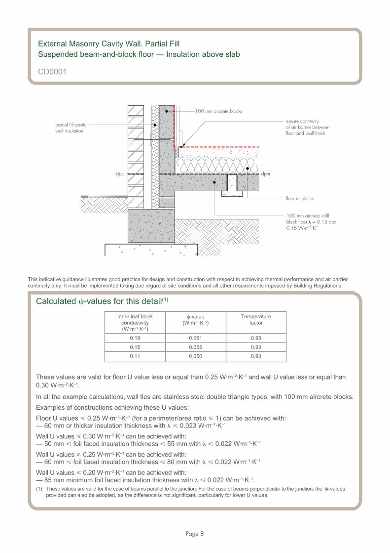
External Masonry Cavity Wall. Partial Fill
Suspended beam-and-block floor — Insulation above slab
ventilated void
partial fill cavitywall insulation
aircrete concrete blockinner leaf above andbelow dpc
wall insulation to continueat least 215 mm fromtop of beam
aircrete foundation blocks
dpc
perimeter insulation
floor insulation
dpm
precast beam-and-block floor withaircrete infill blocks
CD0001
Issued: 1 June 2012
Notes• perimeter insulation with a minimum resistance value of 0.8 m2·K·W–1 (eg 20 mm of insulation with
� = 0.025 W·m–1·K–1) and installed up to floor finish
• ensure that floor insulation tightly abuts blockwork wall
• ensure that the partial fill insulation is secured firmly against the inner leaf of the cavity wall and continues at least 215 mm from top of beam. Care must be taken when the partial fill insulation is taken to the ground, as the product must be fit for purpose with regards to water absorption. If this is not the case, a void may be required between the bottom of the insulation and the top of the foundation block
• ensure cavities and wall ties are kept clean of mortar or other debris during construction
• ensure there is a seal between the wall and the floor air barrier, and that there are no gaps between the skirting board and the floor
• other improved air barrier continuity solutions can be used.
This indicative guidance illustrates good practice for design and construction with respect to achieving thermal performance and air barrier continuity only. It must be implemented taking due regard of site conditions and all other requirements imposed by Building Regulations.
Page 7
dpmdpc
partial fill cavitywall insulation
ensure continuityof air barrier betweenfloor and wall finish
floor insulation
d ‘ l’ l f b b d
100 mm aircrete infillblock floor = 0.15 and0.16
�W·m ·K–1 –1
100 mm aircrete blocks
External Masonry Cavity Wall. Partial FillSuspended beam-and-block floor — Insulation above slab
CD0001
This indicative guidance illustrates good practice for design and construction with respect to achieving thermal performance and air barrier continuity only. It must be implemented taking due regard of site conditions and all other requirements imposed by Building Regulations.
Calculated �-values for this detail(1)
Inner leaf blockconductivity(W·m–1·K–1)
�-value(W·m–1·K–1)
Temperaturefactor
0.19 0.061 0.93
0.15 0.055 0.93
0.11 0.050 0.93
These values are valid for floor U value less or equal than 0.25 W·m–2·K–1 and wall U value less or equal than 0.30 W·m–2·K–1.
In all the example calculations, wall ties are stainless steel double triangle types, with 100 mm aircrete blocks.Examples of constructions achieving these U values:Floor U values � 0.25 W·m–2·K–1 (for a perimeter/area ratio � 1) can be achieved with:— 60 mm or thicker insulation thickness with � � 0.023 W·m–1·K–1
Wall U values � 0.30 W·m–2·K–1 can be achieved with:— 50 mm � foil faced insulation thickness � 55 mm with � � 0.022 W·m–1·K–1
Wall U values � 0.25 W·m–2·K–1 can be achieved with:— 60 mm � foil faced insulation thickness � 80 mm with � � 0.022 W·m–1·K–1
Wall U values � 0.20 W·m–2·K–1 can be achieved with:— 85 mm minimum foil faced insulation thickness with � � 0.022 W·m–1·K–1.(1) These values are valid for the case of beams parallel to the junction. For the case of beams perpendicular to the junction, the �-values
provided can also be adopted, as the difference is not significant, particularly for lower U values.
Page 8
Notes (include details of any corrective action)
External Masonry Cavity Wall. Partial FillSuspended beam-and-block floor — Insulation above slab
CD0001
Guidance checklistDate: ................................................... Site manager/supervisor: .............................................................................
Site name: .................................................................................................... Plot No: .............................................
Ref Item Yes/No Inspected (initials and date)
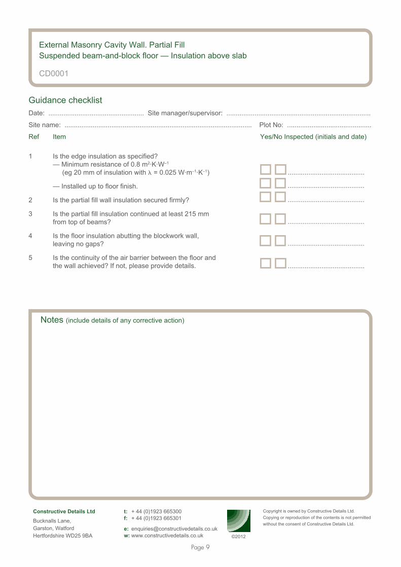
1 Is the edge insulation as specified? — Minimum resistance of 0.8 m2·K·W–1
(eg 20 mm of insulation with � = 0.025 W·m–1·K–1)
— Installed up to floor finish.
2 Is the partial fill wall insulation secured firmly?
3 Is the partial fill insulation continued at least 215 mm from top of beams?
4 Is the floor insulation abutting the blockwork wall, leaving no gaps?
5 Is the continuity of the air barrier between the floor and the wall achieved? If not, please provide details.
Copyright is owned by Constructive Details Ltd. Copying or reproduction of the contents is not permitted without the consent of Constructive Details Ltd.
Constructive Details Ltd
Bucknalls Lane,Garston, WatfordHertfordshire WD25 9BA
t: + 44 (0)1923 665300 f: + 44 (0)1923 665301
e: [email protected] w: www.constructivedetails.co.uk
.........................................
.........................................
.........................................
.........................................
.........................................
©2012
.........................................
Page 9
External Masonry Cavity Wall. Partial Fill
Suspended in-situ concrete floor — Insulation below slab
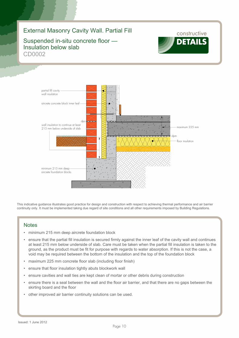
dpm
floor insulation
maximum 225 mm
partial fill cavitywall insulation
aircrete concrete block inner leaf
dpcwall insulation to continue at least215 mm below underside of slab
minimum 215 mm deepaircrete foundation blocks
CD0002
Issued: 1 June 2012
Notes• minimum 215 mm deep aircrete foundation block
• ensure that the partial fill insulation is secured firmly against the inner leaf of the cavity wall and continues at least 215 mm below underside of slab. Care must be taken when the partial fill insulation is taken to the ground, as the product must be fit for purpose with regards to water absorption. If this is not the case, a void may be required between the bottom of the insulation and the top of the foundation block
• maximum 225 mm concrete floor slab (including floor finish)
• ensure that floor insulation tightly abuts blockwork wall
• ensure cavities and wall ties are kept clean of mortar or other debris during construction
• ensure there is a seal between the wall and the floor air barrier, and that there are no gaps between the skirting board and the floor
• other improved air barrier continuity solutions can be used.
This indicative guidance illustrates good practice for design and construction with respect to achieving thermal performance and air barrier continuity only. It must be implemented taking due regard of site conditions and all other requirements imposed by Building Regulations.
Page 10

floor insulation
dpm
dpc
ensure continuity of airbarrier between floorand wall finish
partial fill cavitywall insulation
100 mm aircrete block
denotes 'notional' line of continuous air barrier to be maintained
External Masonry Cavity Wall. Partial Fill Suspended in-situ concrete floor — Insulation below slab
CD0002
This indicative guidance illustrates good practice for design and construction with respect to achieving thermal performance and air barrier continuity only. It must be implemented taking due regard of site conditions and all other requirements imposed by Building Regulations.
Calculated �-values for this detailCase 1: Floor U value between 0.08 and 0.11 W·m–2·K–1 (for a perimeter/area ratio of 0.25)
For example, floor U values for the range shown above can be achieved with insulation thickness between 130 mm and 200 mm and with � � 0.023 W·m–1·K–1.
Wall U value less or equal than 0.20 W·m–2·K–1
Wall U value between 0.21 and 0.25 W·m–2·K–1
Wall U value between 0.26 and 0.30 W·m–2·K–1
Inner leaf block conductivity(W·m–1·K–1)
�-value (W·m–1·K–1)
Temperature factor
�-value (W·m–1·K–1)
Temperature factor
�-value (W·m–1·K–1)
Temperature factor
0.19 0.128 0.92 0.142 0.91 0.156 0.91
0.15 0.119 0.93 0.134 0.92 0.150 0.91
0.11 0.121 0.92 0.139 0.91 0.160 0.90
The table below provides U values for the same floor construction for P/A ratios other than 0.25. The �-values can only be used when the actual floor U value is less than that given for the P/A ratio relevant to the dwelling in question:
P/A (m·m–2) 0.20 0.25 0.30 0.35 0.40 0.45 0.50 0.55 0.60 0.65 0.70 0.75 0.80 0.85 0.90 0.95 1.00
U value (W·m–2·K–1) 0.11 0.11 0.12 0.12 0.13 0.13 0.13 0.13 0.13 0.14 0.14 0.14 0.14 0.14 0.14 0.14 0.14
Page 11
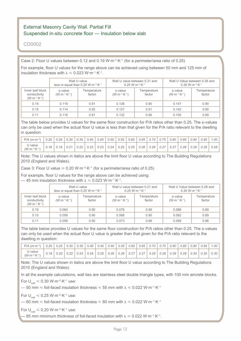
Case 2: Floor U values between 0.12 and 0.19 W·m–2·K–1 (for a perimeter/area ratio of 0.25)
For example, floor U values for the range above can be achieved using between 50 mm and 125 mm of insulation thickness with � � 0.023 W·m–1·K–1.
Wall U value less or equal than 0.20 W·m–2·K–1
Wall U value between 0.21 and 0.25 W·m–2·K–1
Wall U Value between 0.26 and0.30 W·m–2·K–1
Inner leaf block conductivity (W·m–1·K–1)
�-value (W·m–1·K–1)
Temperature factor
�-value (W·m–1·K–1)
Temperature factor
�-value (W·m–1·K–1)
Temperature factor
0.19 0.119 0.91 0.136 0.90 0.147 0.90
0.15 0.114 0.92 0.127 0.91 0.142 0.90
0.11 0.116 0.91 0.132 0.90 0.150 0.89
The table below provides U values for the same floor construction for P/A ratios other than 0.25. The �-values can only be used when the actual floor U value is less than that given for the P/A ratio relevant to the dwelling in question:
P/A (m·m–2) 0.20 0.25 0.30 0.35 0.40 0.45 0.50 0.55 0.60 0.65 0.70 0.75 0.80 0.85 0.90 0.95 1.00
U value (W·m–2·K–1) 0.18 0.19 0.21 0.22 0.23 0.23 0.24 0.25 0.25 0.26 0.26 0.27 0.27 0.28 0.28 0.28 0.28
Note: The U values shown in italics are above the limit floor U value according to The Building Regulations 2010 (England and Wales).
Case 3: Floor U value � 0.20 W·m–2·K–1 (for a perimeter/area ratio of 0.25)
For example, floor U values for the range above can be achieved using:— 45 mm insulation thickness with � � 0.023 W·m–1·K–1.
Wall U value less or equal than 0.20 W·m–2·K–1
Wall U value between 0.21 and 0.25 W·m–2·K–1
Wall U Value between 0.26 and0.30 W·m–2·K–1
Inner leaf block conductivity (W·m–1·K–1)
�-value (W·m–1·K–1)
Temperature factor
�-value (W·m–1·K–1)
Temperature factor
�-value (W·m–1·K–1)
Temperature factor
0.19 0.064 0.90 0.076 0.89 0.086 0.89
0.15 0.056 0.90 0.068 0.90 0.082 0.89
0.11 0.058 0.90 0.073 0.89 0.089 0.88
The table below provides U values for the same floor construction for P/A ratios other than 0.25. The �-values can only be used when the actual floor U value is greater than that given for the P/A ratio relevant to the dwelling in question:
P/A (m·m–2) 0.20 0.25 0.30 0.35 0.40 0.45 0.50 0.55 0.60 0.65 0.70 0.75 0.80 0.85 0.90 0.95 1.00
U value (W·m–2·K–1) 0.18 0.20 0.22 0.23 0.24 0.25 0.26 0.26 0.27 0.27 0.28 0.28 0.29 0.29 0.30 0.30 0.30
Note: The U values shown in italics are above the limit floor U value according to The Building Regulations 2010 (England and Wales).
In all the example calculations, wall ties are stainless steel double triangle types, with 100 mm aircrete blocks. For Uwall � 0.30 W·m–2·K–1 use:— 50 mm � foil-faced insulation thickness � 55 mm with � � 0.022 W·m–1·K–1
For Uwall � 0.25 W·m–2·K–1 use:— 60 mm � foil-faced insulation thickness � 80 mm with � � 0.022 W·m–1·K–1
For Uwall � 0.20 W·m–2·K–1 use:— 85 mm minimum thickness of foil-faced insulation with � � 0.022 W·m–1·K–1.
External Masonry Cavity Wall. Partial Fill Suspended in-situ concrete floor — Insulation below slab
CD0002
Page 12

Notes (include details of any corrective action)
External Masonry Cavity Wall. Partial Fill Suspended in-situ concrete floor — Insulation below slab
CD0002
Guidance checklistDate: ................................................... Site manager/supervisor: .............................................................................
Site name: .................................................................................................... Plot No: .............................................
Ref Item Yes/No Inspected (initials and date)
1 Is the partial fill wall insulation secured firmly?
2 Is the partial fill insulation continued at least 215 mm below underside of slab?
3 Is the floor insulation abutting the blockwork wall, leaving no gaps?
4 Are the foundations at least 215 mm of aircrete blocks?
5 Is the concrete floor slab 225 mm maximum (including floor finish)?
6 Is the continuity of the air barrier between the floor and the wall achieved? If not, please provide details.
Copyright is owned by Constructive Details Ltd.Copying or reproduction of the contents is not permitted without the consent of Constructive Details Ltd.
Constructive Details Ltd
Bucknalls Lane,Garston, WatfordHertfordshire WD25 9BA
t: + 44 (0)1923 665300 f: + 44 (0)1923 665301
e: [email protected] w: www.constructivedetails.co.uk
.........................................
.........................................
.........................................
.........................................
.........................................
.........................................
©2012
Page 13

Page 14
External Masonry Cavity Wall. Partial Fill
Concrete ground bearing floor — Insulation below slab
dpm
dpc
floor insulation
partial fill cavitywall insulation
aircrete concrete blockinner leaf
minimum 215 mmaircrete foundationblocks
wall insulation to continueat least 215 mm belowunderside of slab
maximum 225 mmconcrete slab
perimeter insulation
CD0003
Issued: 1 June 2012
Notes• perimeter insulation with a minimum resistance value of 0.8 m2·K·W–1 (eg 20 mm of insulation with � =
0.025 W·m–1·K–1) and installed up to floor finish
• minimum 215 mm aircrete foundation block
• ensure that the partial fill insulation is secured firmly against the inner leaf of the cavity wall and continues at least 215 mm below underside of slab. Care must be taken when the partial fill insulation is taken to the ground, as the product must be fit for purpose with regards to water absorption. If this is not the case, a void may be required between the bottom of the insulation and the top of the foundation block
• maximum 225 mm concrete floor slab (including floor finish)
• ensure that floor insulation tightly abuts the blockwork wall
• ensure cavities and wall ties are kept clean of mortar or other debris during construction
• ensure there is a seal between the wall and the floor air barrier, and that there are no gaps between the skirting board and the floor
• other improved air barrier continuity solutions can be used.
This indicative guidance illustrates good practice for design and construction with respect to achieving thermal performance and air barrier continuity only. It must be implemented taking due regard of site conditions and all other requirements imposed by Building Regulations.

Page 15
partial fill cavitywall insulation
ensure continuityof air barrier betweenfloor and wall finish
100 mm aircrete block
denotes 'notional' line of continuous air barrier to be maintained
floor insulation
External Masonry Cavity Wall. Partial FillConcrete ground bearing floor — Insulation below slab
CD0003
This indicative guidance illustrates good practice for design and construction with respect to achieving thermal performance and air barrier continuity only. It must be implemented taking due regard of site conditions and all other requirements imposed by Building Regulations.
Calculated �-values for this detailCase 1: Floor U value between 0.08 and 0.11 W·m–2·K–1 (for a perimeter/area ratio of 0.25)
For example, floor U values for the range shown above can be achieved with insulation thickness between 130 mm and 200 mm and with � � 0.023 W·m–1·K–1.
Wall U value less or equal than 0.20 W·m–2·K–1
Wall U value between 0.21 and 0.25 W·m–2·K–1
Wall U value between0.26 and 0.30 W·m–2·K–1
Inner leaf block conductivity(W·m–1·K–1)
�-value (W·m–1·K–1)
Temperature factor
�-value (W·m–1·K–1)
Temperature factor
�-value (W·m–1·K–1)
Temperature factor
0.19 0.083 0.94 0.090 0.94 0.096 0.93
0.15 0.077 0.95 0.084 0.94 0.090 0.94
0.11 0.069 0.95 0.077 0.94 0.084 0.94
The table below provides U values for the same floor construction for P/A ratios other than 0.25. The �-values can only be used when the actual floor U value is less than that given for the P/A ratio relevant to the dwelling in question:
P/A (m·m–2) 0.20 0.25 0.30 0.35 0.40 0.45 0.50 0.55 0.60 0.65 0.70 0.75 0.80 0.85 0.90 0.95 1.00
U value(W·m–2·K–1) 0.11 0.11 0.12 0.12 0.13 0.13 0.13 0.13 0.13 0.14 0.14 0.14 0.14 0.14 0.14 0.14 0.14

Page 16
Case 2: Floor U value between 0.12 and 0.19 W·m–2·K–1 (for a perimeter/area ratio of 0.25)
For example, floor U values for the range above can be achieved using between 50 mm and 125 mm of insulation thickness with � � 0.023 W·m–1·K–1.
Wall U value less or equal than 0.20 W·m–2·K–1
Wall U value between 0.21 and 0.25 W·m–2·K–1
Wall U value between 0.26 and 0.30 W·m–2·K–1
Inner leaf block conductivity(W·m–1·K–1)
�-value(W·m–1·K–1)
Temperaturefactor
�-value(W·m–1·K–1)
Temperaturefactor
�-value(W·m–1·K–1)
Temperaturefactor
0.19 0.079 0.94 0.087 0.93 0.093 0.93
0.15 0.073 0.94 0.080 0.93 0.087 0.93
0.11 0.067 0.94 0.074 0.94 0.082 0.93
The table below provides U values for the same floor construction for P/A ratios other than 0.25. The �-values can only be used when the actual floor U value is less than that given for the P/A ratio relevant to the dwelling in question:
P/A (m·m–2) 0.20 0.25 0.30 0.35 0.40 0.45 0.50 0.55 0.60 0.65 0.70 0.75 0.80 0.85 0.90 0.95 1.00
U value(W·m–2·K–1) 0.18 0.19 0.21 0.22 0.23 0.23 0.24 0.25 0.25 0.26 0.26 0.27 0.27 0.28 0.28 0.28 0.28
Note: The U values shown in italics are above the limit floor U value according to The Building Regulations 2010 (England and Wales).
Case 3: Floor U value higher and equal to 0.20 W·m–2·K–1 (for a perimeter/area ratio of 0.25)
For example, floor U values for the range above can be achieved using 45 mm of insulation thickness with � � 0.023 W·m–1·K–1.
Wall U value less or equal than 0.20 W·m–2·K–1
Wall U value between0.21 and 0.25 W·m–2·K–1
Wall U value between0.26 and 0.30 W·m–2·K–1
Inner leaf block conductivity(W·m–1·K–1)
�-value(W·m–1·K–1)
Temperaturefactor
�-value(W·m–1·K–1)
Temperaturefactor
�-value(W·m–1·K–1)
Temperaturefactor
0.19 0.036 0.93 0.043 0.92 0.049 0.92
0.15 0.030 0.93 0.037 0.92 0.044 0.92
0.11 0.025 0.93 0.033 0.92 0.041 0.92
The table below provides U values for the same floor construction for P/A ratios other than 0.25. The �-values can only be used when the actual floor U value is greater than that given for the P/A ratio relevant to the dwelling in question:
P/A (m·m–2) 0.20 0.25 0.30 0.35 0.40 0.45 0.50 0.55 0.60 0.65 0.70 0.75 0.80 0.85 0.90 0.95 1.00
U value(W·m–2·K–1) 0.18 0.20 0.22 0.23 0.24 0.25 0.26 0.26 0.27 0.27 0.28 0.28 0.29 0.29 0.30 0.30 0.30
Note: The U values shown in italics are above the limit floor U value according to The Building Regulations 2010 (England and Wales).
In all the example calculations, wall ties are stainless steel double triangle types, with 100 mm aircrete blocks.
Wall U values � 0.30 W·m–2·K–1 can be achieved with:— 50 mm � foil-faced insulation � 55 mm with � � 0.022 W·m–1·K–1 or less
Wall U values � 0.25 W·m–2·K–1 can be achieved with:— between 60 mm and 80 mm of foil-faced insulation with conductivity of 0.022 W·m–1·K–1 or less
Wall U values � 0.20 W·m–2·K–1 can be achieved with:— minimum 85 mm of foil-faced insulation with conductivity of 0.022 W·m–1·K–1 or less.
External Masonry Cavity Wall. Partial FillConcrete ground bearing floor — Insulation below slab
CD0003

Page 17
Notes (include details of any corrective action)
External Masonry Cavity Wall. Partial FillConcrete ground bearing floor — Insulation below slab
CD0003
Guidance checklistDate: ................................................... Site manager/supervisor: .............................................................................
Site name: .................................................................................................... Plot No: .............................................
Ref Item Yes/No Inspected (initials and date)
1 Is the edge insulation as specified? — Minimum resistance of 0.8 m2·K·W–1
(eg 20 mm of insulation with � = 0.025 W·m–1·K–1) — Installed up to floor finish.
2 Is the partial fill wall insulation secured firmly?
3 Is the partial fill insulation continued at least 215 mm below underside of slab?
4 Is the floor insulation abutting the blockwork wall leaving no gaps?
5 Are the foundations at least 215 mm deep of aircrete blocks?
6 Is the concrete floor slab 225 mm maximum (including floor finish)?
7 Is the continuity of the air barrier between the floor and the wall achieved? If not, please provide details.
Copyright is owned by Constructive Details Ltd.Copying or reproduction of the contents is not permitted without the consent of Constructive Details Ltd.
Constructive Details Ltd
Bucknalls Lane,Garston, WatfordHertfordshire WD25 9BA
t: + 44 (0)1923 665300f: + 44 (0)1923 665301
e: [email protected] w: www.constructivedetails.co.uk
.........................................
.........................................
.........................................
.........................................
.........................................
©2012
.........................................
.........................................
.........................................

Page 18
External Masonry Cavity Wall. Partial Fill
Independent lintel
minimum frameoverlap 30 mm
clear cavity
cavity width
aircrete concrete blockinner leaf
PVC-U cavity closerfully insulated
CD0004
Issued: 1 June 2012
Notes• PVC-U cavity closer fully insulated with conductivity 0.038 W·m–1·K–1 or less
• a steel or concrete box lintel can be used
• minimum frame overlap of 30 mm
• maximum cavity width of 200 mm
• minimum clear cavity of 50 mm
• ensure that the partial fill insulation is secured firmly against the inner leaf of the cavity wall
• ensure cavities and wall ties are kept clean of mortar or other debris during construction
• flexible sealant should be applied between frame and brickwork and frame and plasterboard
• other improved air barrier continuity solutions can be used.
This indicative guidance illustrates good practice for design and construction with respect to achieving thermal performance and air barrier continuity only. It must be implemented taking due regard of site conditions and all other requirements imposed by Building Regulations.

Page 19
denotes ‘notional’ line of continuous air barrier to be maintained
perimeter sealant betweenframe and plasterboard
perimeter sealant betweenframe and brickwork
100 mm aircrete blocks
partial fill cavity wall insulation
External Masonry Cavity Wall. Partial FillIndependent lintel
CD0004
This indicative guidance illustrates good practice for design and construction with respect to achieving thermal performance and air barrier continuity only. It must be implemented taking due regard of site conditions and all other requirements imposed by Building Regulations.
Calculated �-values for this detail
Wall U value less or equal than 0.20 W·m–2·K–1
Wall U value between 0.21 and 0.25 W·m–2·K–1
Wall U value between 0.26 and 0.30 W·m–2·K–1
Inner leaf block conductivity(W·m–1·K–1)
�-value(W·m–1·K–1)
Temperature factor
�-value(W·m–1·K–1)
Temperature factor
�-value(W·m–1·K–1)
Temperature factor
0.19 0.058 0.89 0.055 0.88 0.054 0.88
0.15 0.058 0.89 0.056 0.88 0.056 0.88
0.11 0.059 0.89 0.059 0.88 0.060 0.88
In all the example calculations, wall ties are stainless steel double triangle types, with 100 mm aircrete blocks.
Examples of constructions achieving the required wall U values are shown below.
Wall U values � 0.30 W·m–2·K–1 can be achieved with:— between 50 mm and 55 mm of foil-faced insulation with conductivity of 0.022 W·m–1·K–1 or less
Wall U values � 0.25 W·m–2·K–1 can be achieved with:— between 60 mm and 80 mm of foil-faced insulation with conductivity of 0.022 W·m–1·K–1 or less
Wall U values � 0.20 W·m–2·K–1 can be achieved with:— minimum 85 mm of foil-faced insulation with conductivity of 0.022 W·m–1·K–1 or less.

Page 20
Notes (include details of any corrective action)
External Masonry Cavity Wall. Partial FillIndependent lintel
CD0004
Guidance checklistDate: ................................................... Site manager/supervisor: .............................................................................
Site name: .................................................................................................... Plot No: .............................................
Ref Item Yes/No Inspected (initials and date)
1 Is the PVC-U cavity closer fully insulated with insulation conductivity equal or less than 0.038 W·m–1·K–1?
2 Is the window frame overlap at least 30 mm?
3 Is the wall cavity width 200 mm or less?
4 Is the clear cavity 50 mm or more?
5 Is the partial fill wall insulation secured firmly?
6 Is the continuity of the air barrier achieved? If not, please provide details.
Copyright is owned by Constructive Details Ltd.Copying or reproduction of the contents is not permitted without the consent of Constructive Details Ltd.
Constructive Details Ltd
Bucknalls Lane,Garston, WatfordHertfordshire WD25 9BA
t: + 44 (0)1923 665300 f: + 44 (0)1923 665301
e: [email protected] w: www.constructivedetails.co.uk
.........................................
.........................................
.........................................
.........................................
.........................................
.........................................
©2012

Page 21
External Masonry Cavity Wall. Partial Fill
Steel lintel — Perforated base plate (insulated soffit)
cavity width
aircrete concreteblock inner leaf
lintel height
lintel insulation
soffit insulation
partial fill cavitywall insulation
minimum frameoverlap 30 mm
clear cavity
CD0005
Issued: 1 June 2012
Notes• soffit insulation with a minimum resistance value of 0.6 m2·K·W–1 (eg 15 mm of insulation with
� = 0.025 W·m–1·K–1)• maximum thickness of steel lintel of 3.2 mm• equivalent conductivity of base plate 30 W·m–1·K–1 or less• minimum frame overlap of 30 mm• fully insulated lintel• maximum lintel height of 220 mm• maximum cavity width of 200 mm• minimum clear cavity of 50 mm• ensure that the partial fill insulation is secured firmly against the inner leaf of the cavity wall• ensure cavities and wall ties are kept clean of mortar or other debris during construction• flexible sealant should be applied between frame and brickwork, and frame and plasterboard• other improved air barrier continuity solutions can be used.
This indicative guidance illustrates good practice for design and construction with respect to achieving thermal performance and air barrier continuity only. It must be implemented taking due regard of site conditions and all other requirements imposed by Building Regulations.
Page 22
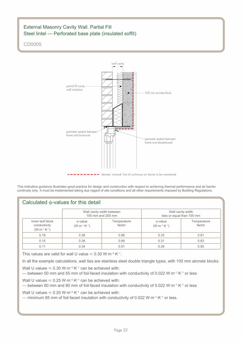
wall cavity
100 mm aircrete block
denotes ‘notional’ line of continuous air barrier to be maintained
partial fill cavitywall insulation
perimeter sealant betweenframe and brickwork
perimeter sealant betweenframe and plasterboard
External Masonry Cavity Wall. Partial FillSteel lintel — Perforated base plate (insulated soffit)
CD0005
This indicative guidance illustrates good practice for design and construction with respect to achieving thermal performance and air barrier continuity only. It must be implemented taking due regard of site conditions and all other requirements imposed by Building Regulations.
Calculated �-values for this detail
Wall cavity width between 100 mm and 200 mm
Wall cavity width less or equal than 100 mm
Inner leaf block conductivity(W·m–1·K–1)
�-value(W·m–1·K–1)
Temperature factor
�-value(W·m–1·K–1)
Temperature factor
0.19 0.38 0.88 0.33 0.81
0.15 0.36 0.89 0.31 0.83
0.11 0.34 0.91 0.28 0.85
This values are valid for wall U value � 0.30 W·m–2·K–1.
In all the example calculations, wall ties are stainless steel double triangle types, with 100 mm aircrete blocks.
Wall U values � 0.30 W·m–2·K–1 can be achieved with:— between 50 mm and 55 mm of foil-faced insulation with conductivity of 0.022 W·m–1·K–1 or less
Wall U values � 0.25 W·m–2·K–1 can be achieved with:— between 60 mm and 80 mm of foil-faced insulation with conductivity of 0.022 W·m–1·K–1 or less
Wall U values � 0.20 W·m–2·K–1 can be achieved with:— minimum 85 mm of foil-faced insulation with conductivity of 0.022 W·m–1·K–1 or less.

Page 23
Notes (include details of any corrective action)
External Masonry Cavity Wall. Partial FillSteel lintel — Perforated base plate (insulated soffit)
CD0005
Guidance checklistDate: ................................................... Site manager/supervisor: .............................................................................
Site name: .................................................................................................... Plot No: .............................................
Ref Item Yes/No Inspected (initials and date)
1 Is the soffit insulation as specified?
— Minimum resistance of 0.6 m2·K–1·W–1
(eg 15 mm of insulation with � = 0.025 W·m–1·K–1).
2 Is the lintel thickness less than 3.2 mm?
3 Is the equivalent thermal conductivity of base plate 30 W·m–1·K–1 or less?
4 Is the lintel height less than 220 mm?
5 Is the window frame overlap at least 30 mm?
6 Is the lintel fully insulated?
7 Is the wall cavity width 200 mm or less?
8 Is the clear cavity 50 mm or more?
9 Is the partial fill wall insulation secured firmly?
10 Is the continuity of the air barrier achieved? If not, please provide details.
Copyright is owned by Constructive Details Ltd. Copying or reproduction of the contents is not permitted without the consent of Constructive Details Ltd.
Constructive Details Ltd
Bucknalls Lane,Garston, WatfordHertfordshire WD25 9BA
t: + 44 (0)1923 665300 f: + 44 (0)1923 665301
e: [email protected] w: www.constructivedetails.co.uk
.........................................
.........................................
.........................................
.........................................
.........................................
.........................................
©2012
.........................................
.........................................
.........................................
.........................................

Page 24
External Masonry Cavity Wall. Partial Fill
Sill
partial fill cavitywall insulation
minimum frameoverlap 30 mm
aircrete concrete blockinner leaf
PVC-U cavity closer fully insulated
cavity width
clear cavity
CD0006
Issued: 1 June 2012
Notes• PVC-U cavity closer fully insulated with conductivity 0.038 W·m–1·K–1 or less
• minimum frame overlap of 30 mm
• maximum cavity width of 200 mm
• minimum clear cavity of 50 mm
• ensure that the partial fill insulation is secured firmly against the inner leaf of the cavity wall
• ensure cavities and wall ties are kept clean of mortar or other debris during construction
• flexible sealant should be applied to the junction of the plasterboard, sill board and also between the window frame member
• other improved air barrier continuity solutions can be used.
This indicative guidance illustrates good practice for design and construction with respect to achieving thermal performance and air barrier continuity only. It must be implemented taking due regard of site conditions and all other requirements imposed by Building Regulations.

Page 25
denotes ‘notional’ line of continuous air barrier to be maintained
100 mm aircrete concrete block
sealant between silland plasterboard
sealant to full perimeter of frameand sill internally and externally
partial fill cavitywall insulation
External Masonry Cavity Wall. Partial FillSill
CD0006
This indicative guidance illustrates good practice for design and construction with respect to achieving thermal performance and air barrier continuity only. It must be implemented taking due regard of site conditions and all other requirements imposed by Building Regulations.
Calculated �-values for this detail
Wall U value less or equal than 0.20 W·m–2·K–1
Wall U value between 0.21 and 0.25 W·m–2·K–1
Wall U value between 0.26 and 0.30 W·m–2·K–1
Inner leaf block conductivity(W·m–1·K–1)
�-value(W·m–1·K–1)
Temperature factor
�-value(W·m–1·K–1)
Temperature factor
�-value(W·m–1·K–1)
Temperature factor
0.19 0.045 0.84 0.037 0.84 0.034 0.84
0.15 0.046 0.84 0.038 0.84 0.035 0.84
0.11 0.046 0.84 0.037 0.84 0.035 0.84
In all the example calculations, wall ties are stainless steel double triangle types, with 100 mm aircrete blocks.
Wall U values � 0.30 W·m–2·K–1 can be achieved with:— between 50 mm and 55 mm of foil-faced insulation with conductivity of 0.022 W·m–1·K–1 or less
Wall U values � 0.25 W·m–2·K–1 can be achieved with:— between 60 mm and 80 mm of foil-faced insulation with conductivity of 0.022 W·m–1·K–1 or less
Wall U values � 0.20 W·m–2·K–1 can be achieved with:— minimum 85 mm of foil-faced insulation with conductivity of 0.022 W·m–1·K–1 or less.

Page 26
Notes (include details of any corrective action)
External Masonry Cavity Wall. Partial FillSill
CD0006
Guidance checklistDate: ................................................... Site manager/supervisor: .............................................................................
Site name: .................................................................................................... Plot No: .............................................
Ref Item Yes/No Inspected (initials and date)
1 Is the PVC-U cavity closer fully insulated with conductivity equal or less than 0.038 W·m–1·K–1?
2 Is the window frame overlap at least 30 mm?
3 Is the wall cavity width 200 mm or less?
4 Is the wall clear cavity 50 mm or more?
5 Is the partial fill wall insulation secured firmly?
6 Is the continuity of the air barrier achieved? If not, please provide details.
Copyright is owned by Constructive Details Ltd. Copying or reproduction of the contents is not permitted without the consent of Constructive Details Ltd.
Constructive Details Ltd
Bucknalls Lane,Garston, WatfordHertfordshire WD25 9BA
t: + 44 (0)1923 665300 f: + 44 (0)1923 665301
e: [email protected] w: www.constructivedetails.co.uk
.........................................
.........................................
.........................................
.........................................
.........................................
.........................................
©2012

Page 27
External Masonry Cavity Wall. Partial Fill
Jamb
aircrete concrete blockinner leaf
PVC-U cavity closerfully insulatedcavity
width
partial fill cavitywall insulation
minimum frameoverlap 30 mm
clear cavity
CD0007
Issued: 1 June 2012
Notes• PVC-U cavity closer fully insulated with conductivity 0.038 W·m–1·K–1 or less
• minimum frame overlap of 30 mm
• maximum cavity width of 200 mm
• minimum clear cavity of 50 mm
• ensure that the partial fill insulation is secured firmly against the inner leaf of the cavity wall
• ensure cavities and wall ties are kept clean of mortar or other debris during construction
• flexible sealant to be applied between the plasterboard, window frame and brickwork
• other improved air barrier continuity solutions can be used.
This indicative guidance illustrates good practice for design and construction with respect to achieving thermal performance and air barrier continuity only. It must be implemented taking due regard of site conditions and all other requirements imposed by Building Regulations.
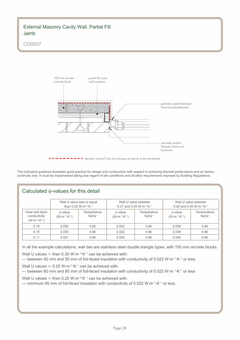
Page 28
100 mm aircreteconcrete block
perimeter sealant betweenframe and plasterboard
perimeter sealantbetween frame andbrickwork
denotes ‘notional’ line of continuous air barrier to be maintained
partial fill cavitywall insulation
External Masonry Cavity Wall. Partial FillJamb
CD0007
This indicative guidance illustrates good practice for design and construction with respect to achieving thermal performance and air barrier continuity only. It must be implemented taking due regard of site conditions and all other requirements imposed by Building Regulations.
Calculated �-values for this detail
Wall U value less or equal than 0.20 W·m–2·K–1
Wall U value between 0.21 and 0.25 W·m–2·K–1
Wall U value between 0.26 and 0.30 W·m–2·K–1
Inner leaf block conductivity(W·m–1·K–1)
�-value(W·m–1·K–1)
Temperature factor
�-value(W·m–1·K–1)
Temperature factor
�-value(W·m–1·K–1)
Temperature factor
0.19 0.050 0.86 0.042 0.86 0.039 0.86
0.15 0.050 0.86 0.042 0.86 0.039 0.86
0.11 0.051 0.86 0.042 0.86 0.040 0.86
In all the example calculations, wall ties are stainless steel double triangle types, with 100 mm aircrete blocks.
Wall U values � than 0.30 W·m–2·K–1 can be achieved with:— between 50 mm and 55 mm of foil-faced insulation with conductivity of 0.022 W·m–1·K–1 or less
Wall U values � 0.25 W·m–2·K–1 can be achieved with:— between 60 mm and 80 mm of foil-faced insulation with conductivity of 0.022 W·m–1·K–1 or less
Wall U values � than 0.20 W·m–2·K–1 can be achieved with:— minimum 85 mm of foil-faced insulation with conductivity of 0.022 W·m–1·K–1 or less.
Page 29
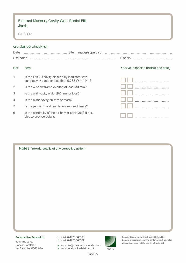
Notes (include details of any corrective action)
External Masonry Cavity Wall. Partial FillJamb
CD0007
Guidance checklistDate: ................................................... Site manager/supervisor: .............................................................................
Site name: .................................................................................................... Plot No: .............................................
Ref Item Yes/No Inspected (initials and date)
1 Is the PVC-U cavity closer fully insulated with conductivity equal or less than 0.038 W·m–1·K–1?
2 Is the window frame overlap at least 30 mm?
3 Is the wall cavity width 200 mm or less?
4 Is the clear cavity 50 mm or more?
5 Is the partial fill wall insulation secured firmly?
6 Is the continuity of the air barrier achieved? If not, please provide details.
Copyright is owned by Constructive Details Ltd. Copying or reproduction of the contents is not permitted without the consent of Constructive Details Ltd.
Constructive Details Ltd
Bucknalls Lane,Garston, WatfordHertfordshire WD25 9BA
t: + 44 (0)1923 665300 f: + 44 (0)1923 665301
e: [email protected] w: www.constructivedetails.co.uk
.........................................
.........................................
.........................................
.........................................
.........................................
.........................................
©2012

Page 30
External Masonry Cavity Wall — Partial Fill
Intermediate timber floor within a dwelling
timber floor joists builtinto inner block leaf
partial fill cavitywall insulation
aircrete concreteblock inner leaf
CD0008
Issued: 1 June 2012
Notes• continue cavity wall insulation across floor abutment zone
• ensure that the partial fill insulation is secured firmly against the inner leaf of the cavity wall
• ensure cavities and wall ties are kept clean of mortar or other debris during construction
• ensure there is a seal between the floor and wall finish, and the ceiling and wall finish
• this detail is also valid for joists supported using joist hangers (not shown in drawing)
• other improved air barrier continuity solutions can be used.
This indicative guidance illustrates good practice for design and construction with respect to achieving thermal performance and air barrier continuity only. It must be implemented taking due regard of site conditions and all other requirements imposed by Building Regulations.

Page 31
partial fill cavitywall insulation
100 mm aircreteconcrete block
ensure continuity of air barrierbetween ceiling and wall finish
ensure continuity of air barrierbetween floor and wall finish
denotes ‘notional’ line of continuous air barrier to be maintained
External Masonry Cavity Wall — Partial FillIntermediate timber floor within a dwelling
CD0008
This indicative guidance illustrates good practice for design and construction with respect to achieving thermal performance and air barrier continuity only. It must be implemented taking due regard of site conditions and all other requirements imposed by Building Regulations.
Calculated �-values for this detail
Inner leaf block conductivity(W·m–1·K–1)
�-value(W·m–1·K–1)
0.19 0.00
0.15 0.00
0.11 0.00
In all the example calculations, wall ties are stainless steel double triangle types, with 100 mm aircrete blocks.
These values are valid for wall U value � 0.30 W·m–2·K–1.Wall U values � 0.30 W·m–2·K–1 can be achieved with:— between 50 mm and 55 mm of foil-faced insulation with conductivity of 0.022 W·m–1·K–1 or lessWall U values � 0.25 W·m–2·K–1 can be achieved with:— between 60 mm and 80 mm of foil-faced insulation with conductivity of 0.022 W·m–1·K–1 or lessWall U values � 0.20 W·m–2·K–1 can be achieved with:— minimum 85 mm of foil-faced insulation with conductivity of 0.022 W·m–1·K–1 or less.

Page 32
Notes (include details of any corrective action)
External Masonry Cavity Wall — Partial FillIntermediate timber floor within a dwelling
CD0008
Guidance checklistDate: ................................................... Site manager/supervisor: .............................................................................
Site name: .................................................................................................... Plot No: .............................................
Ref Item Yes/No Inspected (initials and date)
1 Is the continuity of insulation throughout the junction achieved?
2 Is the partial fill wall insulation secured firmly?
3 Is the continuity of the air barrier achieved? If not, please provide details.
Copyright is owned by Constructive Details Ltd. Copying or reproduction of the contents is not permitted without the consent of Constructive Details Ltd.
Constructive Details Ltd
Bucknalls Lane,Garston, WatfordHertfordshire WD25 9BA
t: + 44 (0)1923 665300 f: + 44 (0)1923 665301
e: [email protected] w: www.constructivedetails.co.uk
.........................................
.........................................
.........................................
©2012

Page 33
External Masonry Cavity Wall. Partial Fill
Precast concrete separating floor between dwellings
partial fill cavitywall insulation
proprietary firestop
aircrete concreteblock inner leaf
concrete screed
precast concreteplank floor
ceiling void
CD0009
Issued: 1 June 2012
Notes• maximum thickness of precast concrete plank floor 225 mm
• maximum thickness of concrete screed 75 mm
• maximum thickness of ceiling void 150 mm
• maximum conductivity of fire stop 0.040 W·m–1·K–1
• ensure continuity of the insulation throughout the junction leaving no gaps
• ensure that the partial fill insulation is secured firmly against the inner leaf of the cavity wall
• ensure cavities and wall ties are kept clean of mortar or other debris during construction
• ensure there is a seal between the wall and the floor air barrier, and that there is no gap between the skirting board and the floor
• other improved air barrier continuity solutions can be used.
This indicative guidance illustrates good practice for design and construction with respect to achieving thermal performance and air barrier continuity only. It must be implemented taking due regard of site conditions and all other requirements imposed by Building Regulations.

Page 34
100 mm aircreteblocks
denotes ‘notional’ line of continuous air barrier to be maintained
partial fill cavitywall insulation
ensure continuityof air barrier
ensure continuityof air barrier
External Masonry Cavity Wall. Partial FillPrecast concrete separating floor between dwellings
CD0009
This indicative guidance illustrates good practice for design and construction with respect to achieving thermal performance and air barrier continuity only. It must be implemented taking due regard of site conditions and all other requirements imposed by Building Regulations.
Calculated �-values for this detail
Wall U value less or equal than 0.20 W·m–2·K–1
Wall U value between 0.21 and 0.25 W·m–2·K–1
Wall U value between 0.26 and 0.30 W·m–2·K–1
Inner leaf block conductivity(W·m–1·K–1)
�-value(W·m–1·K–1)
Temperature factor
�-value(W·m–1·K–1)
Temperature factor
�-value(W·m–1·K–1)
Temperature factor
0.19 0.058 0.97 0.070 0.96 0.086 0.95
0.15 0.057 0.97 0.069 0.96 0.085 0.95
0.11 0.062 0.96 0.074 0.96 0.093 0.94
In all the example calculations, wall ties are stainless steel double triangle types, with 100 mm aircrete blocks.
The �-value is applied to each dwelling.
Wall U values � 0.30 W·m–2·K–1 can be achieved with:— between 50 mm and 55 mm of foil-faced insulation with conductivity of 0.022 W·m–1·K–1 or less
Wall U values � 0.25 W·m–2·K–1 can be achieved with:— between 60 mm and 80 mm of foil-faced insulation with conductivity of 0.022 W·m–1·K–1 or less
Wall U values � 0.20 W·m–2·K–1 can be achieved with:— minimum 85 mm of foil-faced insulation with conductivity of 0.022 W·m–1·K–1 or less.
Page 35
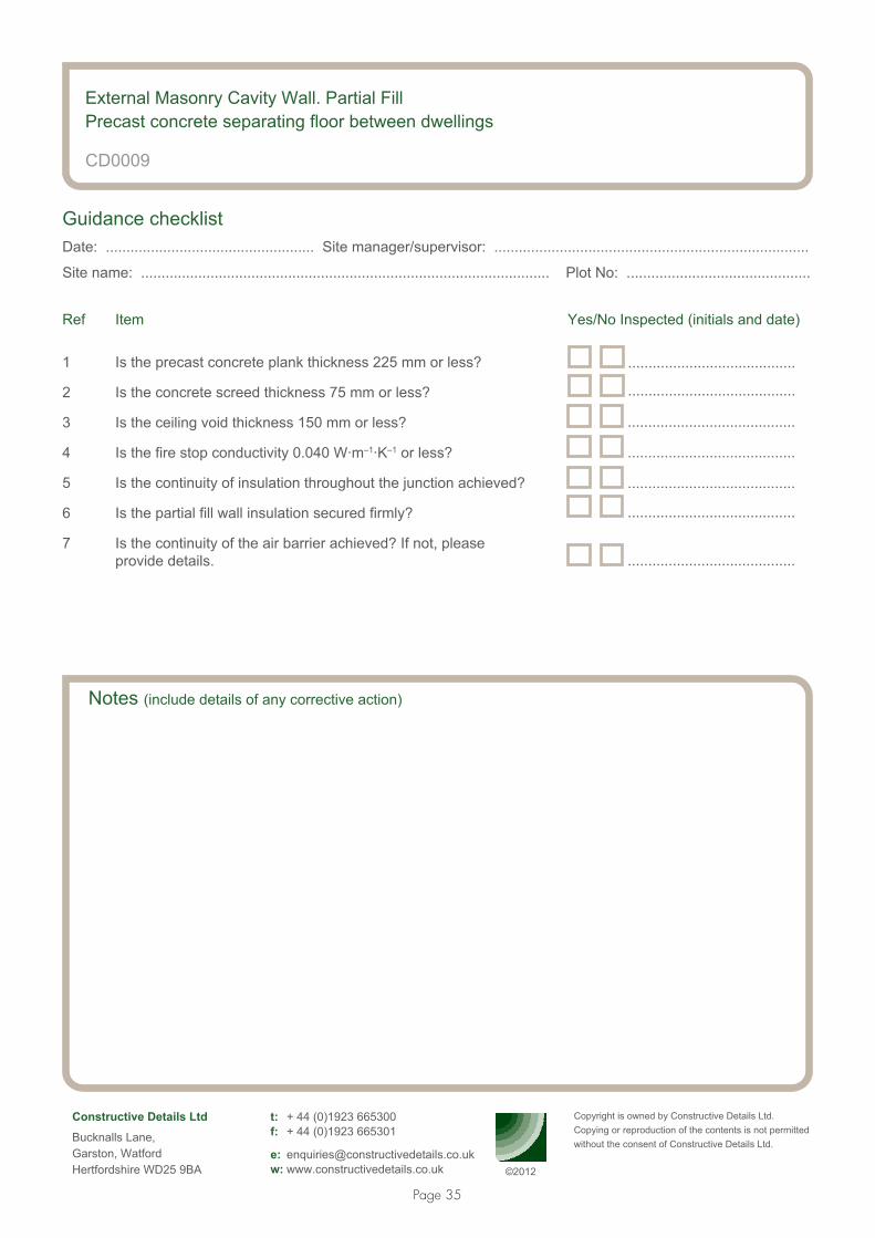
Notes (include details of any corrective action)
External Masonry Cavity Wall. Partial FillPrecast concrete separating floor between dwellings
CD0009
Guidance checklistDate: ................................................... Site manager/supervisor: .............................................................................
Site name: .................................................................................................... Plot No: .............................................
Ref Item Yes/No Inspected (initials and date)
1 Is the precast concrete plank thickness 225 mm or less?
2 Is the concrete screed thickness 75 mm or less?
3 Is the ceiling void thickness 150 mm or less?
4 Is the fire stop conductivity 0.040 W·m–1·K–1 or less?
5 Is the continuity of insulation throughout the junction achieved?
6 Is the partial fill wall insulation secured firmly?
7 Is the continuity of the air barrier achieved? If not, please provide details.
Copyright is owned by Constructive Details Ltd.Copying or reproduction of the contents is not permitted without the consent of Constructive Details Ltd.
Constructive Details Ltd
Bucknalls Lane,Garston, WatfordHertfordshire WD25 9BA
t: + 44 (0)1923 665300 f: + 44 (0)1923 665301
e: [email protected] w: www.constructivedetails.co.uk
.........................................
.........................................
.........................................
.........................................
.........................................
.........................................
©2012
.........................................

Page 36
External Masonry Cavity Wall. Partial Fill
Pitched roof. Gable — Insulation at ceiling level — Ventilated loft
partial fill cavitywall insulation
aircrete concreteblock inner leaf
ceiling insulation
insulation between lasttruss and wall
ventilated loft
minimum 200 mmwall insulation
CD0010
Issued: 1 June 2012
Notes• ceiling insulation thickness between 130 mm and 410 mm
• maximum ceiling insulation conductivity 0.044 W·m–1·K–1
• the wall insulation should continue to at least 200 mm above the top of the ceiling insulation
• ensure that the partial fill insulation is secured firmly against the inner leaf of the cavity wall
• ensure cavities and wall ties are kept clean of mortar or other debris during construction
• pack compressible insulation between last truss/joist and gable wall to prevent any gaps between the insulation and the inner edge of the wall
• seal between the ceiling and wall with either plaster, adhesive or flexible sealant
• other improved air barrier continuity solutions can be used.
This indicative guidance illustrates good practice for design and construction with respect to achieving thermal performance and air barrier continuity only. It must be implemented taking due regard of site conditions and all other requirements imposed by Building Regulations.

Page 37
partial fill cavitywall insulation
100 mm aircrete blocks
perimeter sealant to ensure continuityof air barrier between ceiling andwall finish
ceiling insulation
denotes ‘notional’ line of continuous air barrier to be maintained
External Masonry Cavity Wall. Partial FillPitched roof. Gable — Insulation at ceiling level — Ventilated loft
CD0010
This indicative guidance illustrates good practice for design and construction with respect to achieving thermal performance and air barrier continuity only. It must be implemented taking due regard of site conditions and all other requirements imposed by Building Regulations.
Calculated �-values for this detail Ceiling insulation thickness between
130 mm and 209 mmCeiling insulation thickness between
210 mm and 309 mmCeiling insulation thickness between
310 mm and 410 mm
Inner leaf block conductivity(W·m–1·K–1)
�-value (W·m–1·K–1)
Temperature factor
�-value(W·m–1·K–1)
Temperature factor
�-value(W·m–1·K–1)
Temperature factor
0.19 0.087 0.87 0.071 0.89 0.065 0.90
0.15 0.076 0.88 0.061 0.90 0.057 0.91
0.11 0.063 0.89 0.051 0.91 0.048 0.92
These values are valid for roof U values � 0.20 W·m–2·K–1 and wall U values � 0.30 W·m–2·K–1.
In all the example calculations, wall ties are stainless steel double triangle types, with 100 mm aircrete blocks.
Wall U values � 0.30 W·m–2·K–1 can be achieved with:— between 50-55 mm of foil-faced insulation with conductivity of 0.022 W·m–1·K–1 or less
Wall U values � 0.25 W·m–2·K–1 can be achieved with:— between 60-80 mm of foil-faced insulation with conductivity of 0.022 W·m–1·K–1 or less
Wall U values � 0.20 W·m–2·K–1 can be achieved with:— minimum 85 mm of foil-faced insulation with conductivity of 0.022 W·m–1·K–1 or less.
Page 38
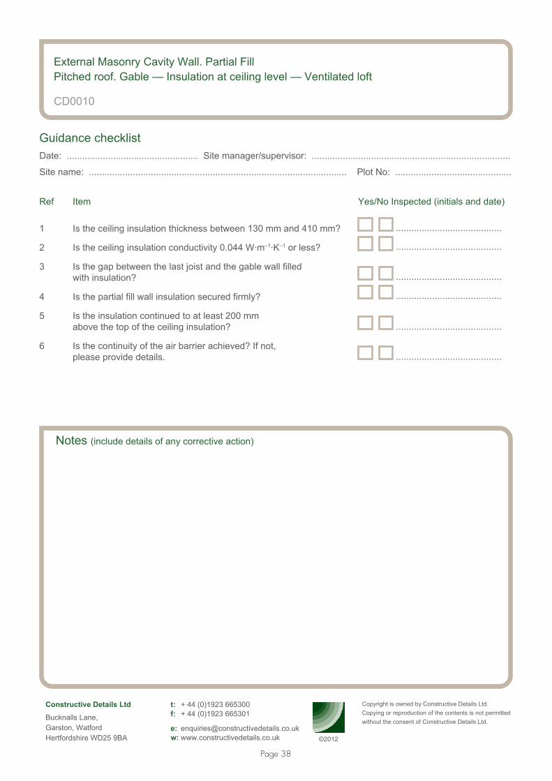
Notes (include details of any corrective action)
External Masonry Cavity Wall. Partial Fill Pitched roof. Gable — Insulation at ceiling level — Ventilated loft
CD0010
Guidance checklistDate: ................................................... Site manager/supervisor: .............................................................................
Site name: .................................................................................................... Plot No: .............................................
Ref Item Yes/No Inspected (initials and date)
1 Is the ceiling insulation thickness between 130 mm and 410 mm?
2 Is the ceiling insulation conductivity 0.044 W·m–1·K–1 or less?
3 Is the gap between the last joist and the gable wall filled with insulation?
4 Is the partial fill wall insulation secured firmly?
5 Is the insulation continued to at least 200 mm above the top of the ceiling insulation?
6 Is the continuity of the air barrier achieved? If not, please provide details.
Copyright is owned by Constructive Details Ltd.Copying or reproduction of the contents is not permitted without the consent of Constructive Details Ltd.
Constructive Details Ltd
Bucknalls Lane,Garston, WatfordHertfordshire WD25 9BA
t: + 44 (0)1923 665300 f: + 44 (0)1923 665301
e: [email protected] w: www.constructivedetails.co.uk
.........................................
.........................................
.........................................
.........................................
.........................................
.........................................
©2012

Page 39
External Masonry Cavity Wall. Partial Fill
Pitched Roof. Gable — Insulation at rafter level
— Unventilated rafter void
partial fill cavitywall insulation
aircrete concreteblock inner leaf
insulation underrafters (optional)
breathable roofmembrane
fill this voidwith insulation
insulation betweenrafter and wall
CD0011
Issued: 1 June 2012
Notes• fill the void between top of the gable and underside of breathable roof membrane (100 mm minimum) with
insulation with conductivity 0.04 W·m–1·K–1 or less. Also fill the gap between rafter and wall
• maximum roof insulation conductivity 0.040 W·m–1·K–1 between 150 mm minimum rafters
• ensure continuity of the insulation throughout the junction leaving no gaps between wall insulation and roof insulation
• ensure that the partial fill insulation is secured firmly against the inner leaf of the cavity wall
• ensure cavities and wall ties are kept clean of mortar or other debris during construction
• use a vapour control layer in the roof plasterboard if required by BS 5250 : 2011
• insulation under or above rafters (not shown in drawing) are optional
• seal between the ceiling and wall with either plaster, adhesive or flexible sealant
• other improved air barrier continuity solutions can be used.
This indicative guidance illustrates good practice for design and construction with respect to achieving thermal performance and air barrier continuity only. It must be implemented taking due regard of site conditions and all other requirements imposed by Building Regulations.

Page 40
denotes 'notional' line of continuous air barrier to be maintained
breathable roofmembrane
insulation betweenrafters
insulation underrafters (optional)
ensure continuityof air barrier
100 mm aircreteblocks
partial fill cavitywall insulation
External Masonry Cavity Wall. Partial FillPitched Roof. Gable — Insulation at rafter level— Unventilated rafter voidCD0011
This indicative guidance illustrates good practice for design and construction with respect to achieving thermal performance and air barrier continuity only. It must be implemented taking due regard of site conditions and all other requirements imposed by Building Regulations.
Calculated �-values for this detail
Inner leaf blockconductivity(W·m–1·K–1)
�-value(W·m–1·K–1)
Temperaturefactor
0.19 0.073 0.90
0.15 0.069 0.91
0.11 0.065 0.91
These values are valid for roof U values equal or less than 0.20 W·m–2·K–1 and wall U values equal or less than 0.30 W·m–2·K–1.
In all the example calculations, wall ties are stainless steel double triangle types, with 100 mm aircrete blocks.
Wall U values � 0.30 W·m–2·K–1 can be achieved with:— between 50-55 mm of foil-faced insulation with conductivity of 0.022 W·m–1·K–1 or less
Wall U values � 0.25 W·m–2·K–1 can be achieved with:— between 60-80 mm of foil-faced insulation with conductivity of 0.022 W·m–1·K–1 or less
Wall U values � 0.20 W·m–2·K–1 can be achieved with:— minimum 85 mm of foil-faced insulation with conductivity of 0.022 W·m–1·K–1 or less.

Page 41
Notes (include details of any corrective action)
External Masonry Cavity Wall. Partial FillPitched Roof. Gable — Insulation at rafter level— Unventilated rafter voidCD0011
Guidance checklistDate: ................................................... Site manager/supervisor: .............................................................................
Site name: .................................................................................................... Plot No: .............................................
Ref Item Yes/No Inspected (initials and date)
1 Is the void between top of the gable and underside of breathable roof membrane 100 mm minimum?
2 Is void between top of the gable and underside of breathable roof membrane filled with insulation with conductivity of 0.04 W·m–1·K–1 or less?
3 Is the gap between rafter and wall filled with insulation with conductivity of 0.04 W·m–1·K–1 or less?
4 Is the roof insulation conductivity 0.040 W·m–1·K–1 or less between 150 mm minimum rafters?
5 Is the continuity of insulation throughout the junction achieved?
6 Is the partial fill wall insulation secured firmly?
7 Is the continuity of the air barrier achieved? If not, please provide details.
Copyright is owned by Constructive Details Ltd.Copying or reproduction of the contents is not permitted without the consent of Constructive Details Ltd.
Constructive Details Ltd
Bucknalls Lane,Garston, WatfordHertfordshire WD25 9BA
t: + 44 (0)1923 665300 f: + 44 (0)1923 665301
e: [email protected] w: www.constructivedetails.co.uk
.........................................
.........................................
.........................................
.........................................
©2012
.........................................
.........................................
.........................................

Page 42
External Masonry Cavity Wall. Partial Fill
Pitched roof. Eaves — Insulation at ceiling level — Ventilated loft
50 mm
min
proprietary ventilatorbetween rafters
ventilated loft
ceiling insulationbetween and over
ssesroof tru
aircrete concreteblock inner leaf
insulation to entirely filleaves gap betweenwall insulation andceiling insulation
minimum 50 mminsulation betweenwall plate and vent
proprietaryfascia ventilator
partial fill cavitywall insulation
CD0012
Issued: 1 June 2012
Notes• maximum wall cavity width of 200 mm
• minimum 50 mm wall clear air cavity
• ceiling insulation thickness between 130 mm and 410 mm
• maximum ceiling insulation conductivity 0.044 W·m–1·K–1
• minimum 50 mm gap between ventilator and wall plate filled with insulation
• insulation to entirely fill eaves gap between wall insulation and ceiling insulation
• ensure that the partial fill insulation is secured firmly against the inner leaf of the cavity wall
• ensure cavities and wall ties are kept clean of mortar or other debris during construction
• seal between the ceiling and wall with either plaster, adhesive or flexible sealant
• other improved air barrier continuity solutions can be used.
This indicative guidance illustrates good practice for design and construction with respect to achieving thermal performance and air barrier continuity only. It must be implemented taking due regard of site conditions and all other requirements imposed by Building Regulations.

Page 43
denotes 'notional' line of continuous air barrier to be maintained
partial fill cavitywall insulation
100 mm aircrete blocks
ensure continuity of airbarrier between ceilingand wall finish
insulation thickness
External Masonry Cavity Wall. Partial FillPitched roof. Eaves — Insulation at ceiling level — Ventilated loft
CD0012
This indicative guidance illustrates good practice for design and construction with respect to achieving thermal performance and air barrier continuity only. It must be implemented taking due regard of site conditions and all other requirements imposed by Building Regulations.
Calculated �-values for this detail
These values are valid for roof U values � 0.20 W·m–2·K–1.
Ceiling insulation thickness between 130 mm and 210 mm Wall U value less or equal than
0.20 W·m–1·K–2Wall U value between
0.21 and 0.25 W·m–1·K–2Wall U value between
0.26 and 0.30 W·m–1·K–2
Inner leaf block conductivity(W·m–1·K–1)
�-value (W·m–1·K–1)
Temperature factor
�-value (W·m–1·K–1)
Temperature factor
�-value (W·m–1·K–1)
Temperature factor
0.19 0.092 0.91 0.081 0.91 0.071 0.90
0.15 0.089 0.91 0.079 0.90 0.069 0.90
0.11 0.086 0.90 0.072 0.90 0.064 0.90
Ceiling insulation thickness between 211 mm and 310 mm Wall U value less or equal than
0.20 W·m–1·K–2Wall U value between
0.21 and 0.25 W·m–1·K–2Wall U value between
0.26 and 0.30 W·m–1·K–2
Inner leaf block conductivity(W·m–1·K–1)
�-value(W·m–1·K–1)
Temperaturefactor
�-value(W·m–1·K–1)
Temperaturefactor
�-value(W·m–1·K–1)
Temperaturefactor
0.19 0.111 0.91 0.100 0.91 0.090 0.90
0.15 0.108 0.91 0.098 0.90 0.088 0.90
0.11 0.105 0.91 0.092 0.90 0.083 0.90

Page 44
Ceiling insulation thickness between 311 mm and 410 mmWall U value less or equal than
0.20 W·m–2·K–1Wall U value between
0.21 and 0.25 W·m–2·K–1Wall U Value between
0.26 and 0.30 W·m–2·K–1
Inner leaf block conductivity(W·m–1·K–1)
�-value(W·m–1·K–1)
Temperaturefactor
�-value(W·m–1·K–1)
Temperaturefactor
�-value(W·m–1·K–1)
Temperaturefactor
0.19 0.128 0.91 0.116 0.91 0.106 0.91
0.15 0.125 0.91 0.114 0.90 0.105 0.90
0.11 0.122 0.91 0.108 0.90 0.099 0.90
In all the example calculations, wall ties are stainless steel double triangle types, with 100 mm aircrete blocks.Wall U values � 0.30 W·m–2·K–1 can be achieved with:— between 50-55 mm of foil-faced insulation with conductivity of 0.022 W·m–1·K–1 or lessWall U values � 0.25 W·m–2·K–1 can be achieved with:— between 60-80 mm of foil-faced insulation with conductivity of 0.022 W·m–1·K–1 or lessWall U values � 0.20 W·m–2·K–1 can be achieved with:— minimum 85 mm of foil-faced insulation with conductivity of 0.022 W·m–1·K–1 or less.
External Masonry Cavity Wall. Partial FillPitched roof. Eaves — Insulation at ceiling level — Ventilated loft
CD0012

Page 45
Notes (include details of any corrective action)
External Masonry Cavity Wall. Partial Fill Pitched Roof. Eaves — Insulation at Ceiling Level — Ventilated Loft
CD0012
Guidance checklistDate: ................................................... Site manager/supervisor: .............................................................................
Site name: .................................................................................................... Plot No: .............................................
Ref Item Yes/No Inspected (initials and date)
1 Is the wall cavity width 200 mm or less?
2 Is the clear cavity 50 mm or more?
3 Is the ceiling insulation thickness between 130 mm and 410 mm?
4 Is the ceiling insulation conductivity 0.044 W·m–1·K–1 or less?
5 Is there a minimum 50 mm gap between ventilator and wall plate filled with insulation?
6 Is the continuity of insulation throughout the junction achieved?
7 Is the partial fill wall insulation secured firmly?
8 Is the continuity of the air barrier achieved? If not, please provide details.
Copyright is owned by Constructive Details Ltd. Copying or reproduction of the contents is not permitted without the consent of Constructive Details Ltd.
Constructive Details Ltd
Bucknalls Lane,Garston, WatfordHertfordshire WD25 9BA
t: + 44 (0)1923 665300 f: + 44 (0)1923 665301
e: [email protected] w: www.constructivedetails.co.uk
.........................................
.........................................
.........................................
.........................................
.........................................
.........................................
©2012
.........................................
.........................................
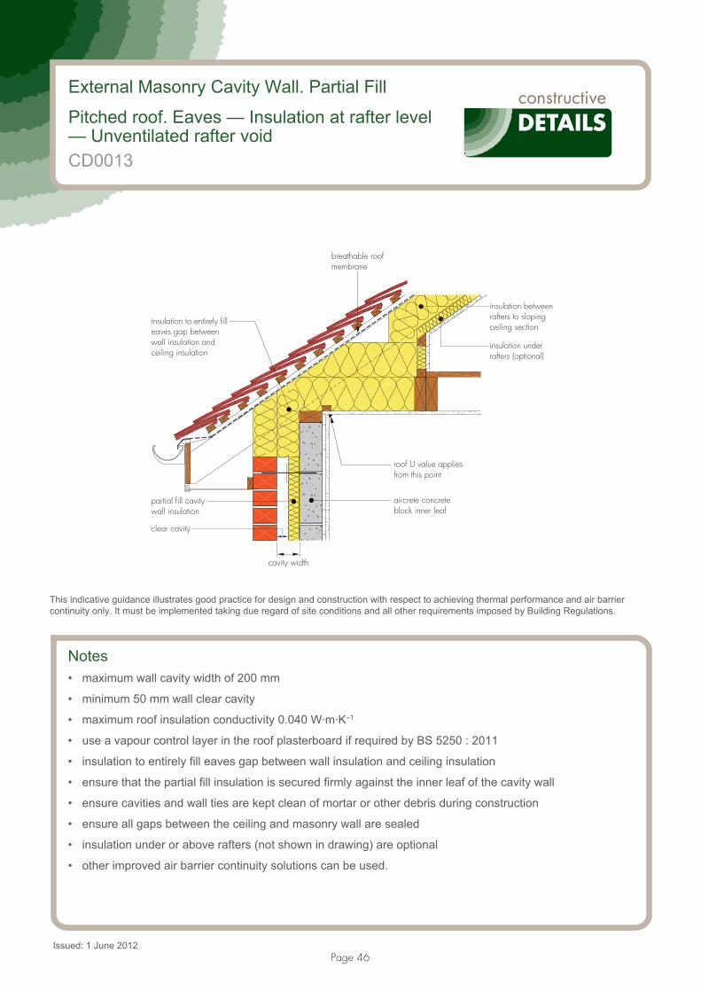
Page 46
External Masonry Cavity Wall. Partial Fill
Pitched roof. Eaves — Insulation at rafter level— Unventilated rafter void
insulation to entirely filleaves gap betweenwall insulation andceiling insulation
partial fill cavitywall insulation
aircrete concreteblock inner leaf
roof U value appliesfrom this point
breathable roofmembrane
insulation betweenrafters to slopingceiling section
insulation underrafters (optional)
clear cavity
cavity width
CD0013
Issued: 1 June 2012
Notes• maximum wall cavity width of 200 mm
• minimum 50 mm wall clear cavity
• maximum roof insulation conductivity 0.040 W·m·K–1
• use a vapour control layer in the roof plasterboard if required by BS 5250 : 2011
• insulation to entirely fill eaves gap between wall insulation and ceiling insulation
• ensure that the partial fill insulation is secured firmly against the inner leaf of the cavity wall
• ensure cavities and wall ties are kept clean of mortar or other debris during construction
• ensure all gaps between the ceiling and masonry wall are sealed
• insulation under or above rafters (not shown in drawing) are optional
• other improved air barrier continuity solutions can be used.
This indicative guidance illustrates good practice for design and construction with respect to achieving thermal performance and air barrier continuity only. It must be implemented taking due regard of site conditions and all other requirements imposed by Building Regulations.

Page 47
denotes 'notional' line of continuous air barrier to be maintained
partial fill cavitywall insulation
100 mm aircrete
ensure continuityof air barrier
breathable roofmembrane
insulation betweenrafters
insulation underrafters, (optional)
External Masonry Cavity Wall. Partial Fill Pitched roof. Eaves — Insulation at rafter level — Unventilated rafter void
CD0013
This indicative guidance illustrates good practice for design and construction with respect to achieving thermal performance and air barrier continuity only. It must be implemented taking due regard of site conditions and all other requirements imposed by Building Regulations.
Calculated �-values for this detail
Wall cavity width between 100 mm and 200 mm
Wall cavity width less or equal than 100 mm
Inner leaf block conductivity (W·m–1·K–1)
�-value(W·m–1·K–1)
Temperature factor
�-value(W·m–1·K–1)
Temperature factor
0.19 0.036 0.95 0.020 0.97
0.15 0.036 0.95 0.020 0.97
0.11 0.035 0.95 0.021 0.97
These values are valid for roof U values � 0.20 W·m–2·K–1 and wall U values � 0.30 W·m–2·K–1.
In all the example calculations, wall ties are stainless steel double triangle types, with 100 mm aircrete blocks.
Wall U values � 0.30 W·m–2·K–1 can be achieved with:— between 50 mm and 55 mm of foil-faced insulation with conductivity of 0.022 W·m–1·K–1 or less
Wall U values � 0.25 W·m–2·K–1 can be achieved with:— between 60 mm and 80 mm of foil-faced insulation with conductivity of 0.022 W·m–1·K–1 or less
Wall U values � 0.20 W·m–2·K–1 can be achieved with:— minimum 85 mm of foil-faced insulation with conductivity of 0.022 W·m–1·K–1 or less.

Page 48
Notes (include details of any corrective action)
External Masonry Cavity Wall. Partial Fill Pitched roof. Eaves — Insulation at rafter level — Unventilated rafter void
CD0013
Guidance checklistDate: ................................................... Site manager/supervisor: .............................................................................
Site name: .................................................................................................... Plot No: .............................................
Ref Item Yes/No Inspected (initials and date)
1 Is the wall cavity width 200 mm or less?
2 Is the clear cavity 50 mm or more?
3 Is the roof insulation conductivity 0.040 W·m–1·K–1 or less between 150 mm minimum rafters?
4 Is the continuity of insulation throughout the junction achieved?
5 Is the eaves gap entirely filled with insulation?
6 Is the partial fill wall insulation secured firmly?
7 Is the continuity of the air barrier achieved? If not, please provide details.
Copyright is owned by Constructive Details Ltd. Copying or reproduction of the contents is not permitted without the consent of Constructive Details Ltd.
Constructive Details Ltd
Bucknalls Lane,Garston, WatfordHertfordshire WD25 9BA
t: + 44 (0)1923 665300 f: + 44 (0)1923 665301
e: [email protected] w: www.constructivedetails.co.uk
.........................................
.........................................
.........................................
.........................................
.........................................
.........................................
©2012
.........................................

Page 49
External Masonry Cavity Wall. Partial Fill
Normal corner
aircrete concreteblock inner leaf
partial fill cavitywall insulation
CD0014
Issued: 1 June 2012
Notes• ensure continuity of the insulation throughout the junction leaving no gaps
• ensure that the partial fill insulation is secured firmly against the inner leaf of the cavity wall
• ensure cavities and wall ties are kept clean of mortar or other debris during construction
• ensure all gaps are sealed
• other improved air barrier continuity solutions can be used.
This indicative guidance illustrates good practice for design and construction with respect to achieving thermal performance and air barrier continuity only. It must be implemented taking due regard of site conditions and all other requirements imposed by Building Regulations.

Page 50
partial fill cavitywall insulation
ensure continuityof air barrier
100 mm aircreteblocks
External Masonry Cavity Wall. Partial FillNormal corner
CD0014
This indicative guidance illustrates good practice for design and construction with respect to achieving thermal performance and air barrier continuity only. It must be implemented taking due regard of site conditions and all other requirements imposed by Building Regulations.
Calculated �-values for this detail
Wall U value less or equal than 0.20 W·m–2·K–1
Wall U value between 0.21 and 0.25 W·m–2·K–1
Wall U value between 0.26 and 0.30 W·m–2·K–1
Inner leaf block conductivity (W·m–1·K–1)
�-value (W·m–1·K–1)
Temperature factor
�-value (W·m–1·K–1)
Temperature factor
�-value (W·m–1·K–1)
Temperature factor
0.19 0.047 0.93 0.052 0.92 0.056 0.90
0.15 0.044 0.93 0.048 0.92 0.052 0.90
0.11 0.040 0.92 0.043 0.91 0.047 0.89
In all the example calculations, wall ties are stainless steel double triangle types, with 100 mm aircrete blocks.
Wall U values � 0.30 W·m–2·K–1 can be achieved with:— between 50 mm and 55 mm of foil-faced insulation with conductivity of 0.022 W·m–1·K–1 or less
Wall U values � 0.25 W·m–2·K–1 can be achieved with:— between 60 mm and 80 mm of foil-faced insulation with conductivity of 0.022 W·m–1·K–1 or less
Wall U values � 0.20 W·m–2·K–1 can be achieved with:— minimum 85 mm of foil-faced insulation with conductivity of 0.022 W·m–1·K–1 or less.

Page 51
Notes (include details of any corrective action)
External Masonry Cavity Wall. Partial FillNormal corner
CD0014
Guidance checklistDate: ................................................... Site manager/supervisor: .............................................................................
Site name: .................................................................................................... Plot No: .............................................
Ref Item Yes/No Inspected (initials and date)
1 Is the continuity of insulation throughout the junction achieved?
2 Is the partial fill wall insulation secured firmly?
3 Is the continuity of the air barrier achieved? If not, please provide details.
Copyright is owned by Constructive Details Ltd.Copying or reproduction of the contents is not permitted without the consent of Constructive Details Ltd.
Constructive Details Ltd
Bucknalls Lane,Garston, WatfordHertfordshire WD25 9BA
t: + 44 (0)1923 665300 f: + 44 (0)1923 665301
e: [email protected] w: www.constructivedetails.co.uk
.........................................
.........................................
.........................................
©2012
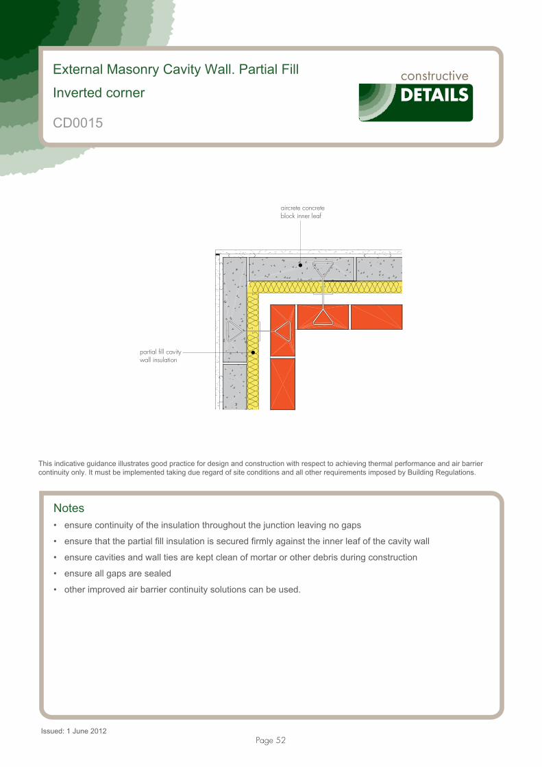
Page 52
External Masonry Cavity Wall. Partial Fill
Inverted corner
aircrete concreteblock inner leaf
partial fill cavitywall insulation
CD0015
Issued: 1 June 2012
Notes• ensure continuity of the insulation throughout the junction leaving no gaps
• ensure that the partial fill insulation is secured firmly against the inner leaf of the cavity wall
• ensure cavities and wall ties are kept clean of mortar or other debris during construction
• ensure all gaps are sealed
• other improved air barrier continuity solutions can be used.
This indicative guidance illustrates good practice for design and construction with respect to achieving thermal performance and air barrier continuity only. It must be implemented taking due regard of site conditions and all other requirements imposed by Building Regulations.

Page 53
denotes 'notional' line of continuous air barrier to be maintained
100 mm aircrete blocksensure continuityof air barrier
partial fill cavitywall insulation
External Masonry Cavity Wall. Partial FillInverted corner
CD0015
This indicative guidance illustrates good practice for design and construction with respect to achieving thermal performance and air barrier continuity only. It must be implemented taking due regard of site conditions and all other requirements imposed by Building Regulations.
Calculated �-values for this detail
Wall U value less or equal than 0.20 W·m–2·K–1
Wall U value between 0.21 and 0.25 W·m–2·K–1
Wall U value between 0.26 and 0.30 W·m–2·K–1
Inner leaf block conductivity (W·m–1·K–1)
�-value (W·m–1·K–1)
Temperature factor
�-value (W·m–1·K–1)
Temperature factor
�-value (W·m–1·K–1)
Temperature factor
0.19 –0.054 0.99 –0.070 0.98 –0.080 0.97
0.15 –0.053 0.99 –0.068 0.98 –0.080 0.97
0.11 –0.052 0.99 –0.066 0.98 –0.077 0.97
In all the example calculations, wall ties are stainless steel double triangle types, with 100 mm aircrete blocks.
Wall U values � 0.30 W·m–2·K–1 can be achieved with:— between 50 mm and 55 mm of foil-faced insulation with conductivity of 0.022 W·m–1·K–1 or less
Wall U values � 0.25 W·m–2·K–1 can be achieved with:— between 60 mm and 80 mm of foil-faced insulation with conductivity of 0.022 W·m–1·K–1 or less
Wall U values � 0.20 W·m–2·K–1 can be achieved with:— minimum 85 mm of foil-faced insulation with conductivity of 0.022 W·m–1·K–1 or less.

Page 54
Notes (include details of any corrective action)
External Masonry Cavity Wall. Partial FillInverted corner
CD0015
Guidance checklistDate: ................................................... Site manager/supervisor: .............................................................................
Site name: .................................................................................................... Plot No: .............................................
Ref Item Yes/No Inspected (initials and date)
1 Is the continuity of insulation throughout the junction achieved?
2 Is the partial fill wall insulation secured firmly?
3 Is the continuity of the air barrier achieved? If not, please provide details.
Copyright is owned by Constructive Details Ltd. Copying or reproduction of the contents is not permitted without the consent of Constructive Details Ltd.
Constructive Details Ltd
Bucknalls Lane,Garston, WatfordHertfordshire WD25 9BA
t: + 44 (0)1923 665300 f: + 44 (0)1923 665301
e: [email protected] w: www.constructivedetails.co.uk
.........................................
.........................................
.........................................
©2012

Page 55
External Masonry Cavity Wall. Partial Fill
Party wall between dwellings
full fill cavity insulationto separating wall
partial fill cavitywall insulation
proprietary insulatedfire stop
party wall cavity width
100 mm aircreteconcrete block innerleaf to external walland separating wallleaves
CD0016
Issued: 1 June 2012
Notes• party wall fully filled with insulation (� = 0.044 W·m–1·K–1 maximum)
• maximum party wall cavity width of 100 mm
• ensure that the insulated fire stop (� = 0.044 W·m–1·K–1 maximum) covers the full width of the abutting wall
• ensure continuity of the insulation throughout the junction leaving no gaps
• ensure that the partial fill insulation is secured firmly against the inner leaf of the cavity wall
• ensure cavities and wall ties are kept clean of mortar or other debris during construction
• ensure all gaps are sealed
• other improved air barrier continuity solutions can be used.
This indicative guidance illustrates good practice for design and construction with respect to achieving thermal performance and air barrier continuity only. It must be implemented taking due regard of site conditions and all other requirements imposed by Building Regulations.

Page 56
ensure continuity ofair barrier betweenwall finishes
100 mm aircrete block
partial fill cavitywall insulation
denotes 'notional' line of continuous air barrier to be maintained
External Masonry Cavity Wall. Partial FillParty wall between dwellings
CD0016
This indicative guidance illustrates good practice for design and construction with respect to achieving thermal performance and air barrier continuity only. It must be implemented taking due regard of site conditions and all other requirements imposed by Building Regulations.
Calculated �-values — party wall aircrete block conductivity of 0.19 W·m–1·K–1
Wall U value
less or equal than 0.20 W·m–2·K–1Wall U value between
0.21 and 0.25 W·m–2·K–1Wall U value between
0.26 and 0.30 W·m–2·K–1
Inner leaf block conductivity(W·m–1·K–1)
�-value (W·m–1·K–1)
Temperature factor
�-value (W·m–1·K–1)
Temperature factor
�-value (W·m–1·K–1)
Temperature factor
0.19 0.037 0.93 0.040 0.93 0.044 0.91
0.15 0.036 0.93 0.040 0.93 0.044 0.91
0.11 0.039 0.93 0.041 0.92 0.046 0.91

Page 57
Calculated �-values — party wall aircrete block conductivity of 0.15 W·m–1·K–1
Wall U value
less or equal than 0.20 W·m–2·K–1Wall U value between
0.21 and 0.25 W·m–2·K–1Wall U value between
0.26 and 0.30 W·m–2·K–1
Inner leaf block conductivity(W·m–1·K–1)
�-value(W·m–1·K–1)
Temperaturefactor
�-value(W·m–1·K–1)
Temperaturefactor
�-value(W·m–1·K–1)
Temperaturefactor
0.19 0.035 0.93 0.039 0.93 0.042 0.91
0.15 0.035 0.93 0.038 0.93 0.041 0.91
0.11 0.037 0.93 0.039 0.92 0.043 0.91
The �-value is applied to each dwelling.
In all the example calculations, wall ties are stainless steel double triangle types, with 100 mm aircrete blocks.
Wall U values � 0.30 W·m–2·K–1 can be achieved with:— between 50 mm and 55 mm of foil-faced insulation with conductivity of 0.022 W·m–1·K–1 or less
Wall U values � 0.25 W·m–2·K–1 can be achieved with:— between 60 mm and 80 mm of foil-faced insulation with conductivity of 0.022 W·m–1·K–1 or less
Wall U values � 0.20 W·m–2·K–1 can be achieved with:— minimum 85 mm of foil-faced insulation with conductivity of 0.022 W·m–1·K–1 or less.
External Masonry Cavity Wall. Partial FillParty wall between dwellings
CD0016

Page 58
Notes (include details of any corrective action)
External Masonry Cavity Wall. Partial FillParty wall between dwellings
CD0016
Guidance checklistDate: ................................................... Site manager/supervisor: .............................................................................
Site name: .................................................................................................... Plot No: .............................................
Ref Item Yes/No Inspected (initials and date)
1 Is the party wall fully filled with insulation of 0.044 W·m–1·K–1 or less?
2 Is the party wall cavity width 100 mm or less?
3 Is the fire stop insulated with a material of 0.044 W·m–1·K–1 or less?
4 Is the fire stop covering the full width of the abutment wall?
5 Is the continuity of insulation throughout the junction achieved?
6 Is the partial fill wall insulation secured firmly?
7 Is the continuity of the air barrier achieved? If not, please provide details.
Copyright is owned by Constructive Details Ltd. Copying or reproduction of the contents is not permitted without the consent of Constructive Details Ltd.
Constructive Details Ltd
Bucknalls Lane,Garston, WatfordHertfordshire WD25 9BA
t: + 44 (0)1923 665300f: + 44 (0)1923 665301
e: [email protected] w: www.constructivedetails.co.uk
.........................................
.........................................
.........................................
.........................................
.........................................
©2012
.........................................
.........................................

Page 59
Party Wall Masonry. Full Fill
Suspended beam-and-block floor — Insulation above slab
dpm
ventilated void ventilated void
at least 215 mmfrom top of beam
party wall cavity width
aircrete foundationblocks
precast beam-and-block floor withaircrete infill blocks
100 mm aircrete concreteblock leaf to separatingwall above and below dpm
floor insulation
perimeterinsulation
CD0017
Issued: 1 June 2012
Notes• party wall fully filled with insulation (� = 0.044 W·m–1·K–1 maximum)
• maximum party wall cavity width of 100 mm
• perimeter insulation with a minimum resistance value of 0.8 m2·K·W–1 (eg 20 mm of insulation with � = 0.025 W·m–1·K–1) and installed up to floor finish
• ensure that the party wall insulation continues at least 215 mm from top of beams
• ensure that floor insulation tightly abuts blockwork wall
• ensure all gaps are sealed
• other improved air barrier continuity solutions can be used.
This indicative guidance illustrates good practice for design and construction with respect to achieving thermal performance and air barrier continuity only. It must be implemented taking due regard of site conditions and all other requirements imposed by Building Regulations.

Page 60
denotes 'notional' line of continuous air barrier to be maintained
ventilated void
ensure continuity ofair barrier betweenfloor and wall finish
floor insulation
100 mm aircreteinfill block floor
= 0.15 or 0.16 W·m ·K� –1–1ventilated void
Party Wall Masonry. Full FillSuspended beam-and-block floor — Insulation above slab
CD0017
This indicative guidance illustrates good practice for design and construction with respect to achieving thermal performance and air barrier continuity only. It must be implemented taking due regard of site conditions and all other requirements imposed by Building Regulations.
Calculated �-values for this detail
Inner leaf blockconductivity(W·m–1·K–1)
�-value(W·m–1·K–1)
Temperaturefactor
0.19 0.049 0.95
0.15 0.043 0.95
The �-value is applied to each dwelling.
These values are valid for floor U value � 0.25 W·m–2·K–1.
Floor U values � 0.25 W·m–2·K–1 (for a perimeter/area ratio � 1) can be achieved with:
— 100 mm aircrete infill block floor.— 60 mm or thicker insulation with conductivity of 0.023 W·m–1·K–1 or less.

Page 61
Notes (include details of any corrective action)
Party Wall Masonry. Full FillSuspended beam-and-block floor — Insulation above slab
CD0017
Guidance checklistDate: ................................................... Site manager/supervisor: .............................................................................
Site name: .................................................................................................... Plot No: .............................................
Ref Item Yes/No Inspected (initials and date)
1 Is the edge insulation as specified? — Minimum resistance of 0.8 m2·K1·W–1
(eg 20 mm of insulation with � = 0.025 W·m–1·K–1) — Installed up to floor finish
2 Is the party wall insulation continued at least 215 mm from top of beams?
3 Is the floor insulation abutting the blockwork wall, leaving no gaps?
4 Is the party wall fully filled with insulation of 0.044 W·m–1·K–1 or less?
5 Is the party wall cavity width 100 mm or less?
6 Is the continuity of the air barrier achieved? If not, please provide details.
Copyright is owned by Constructive Details Ltd. Copying or reproduction of the contents is not permitted without the consent of Constructive Details Ltd.
Constructive Details Ltd
Bucknalls Lane,Garston, WatfordHertfordshire WD25 9BA
t: + 44 (0)1923 665300 f: + 44 (0)1923 665301
e: [email protected] w: www.constructivedetails.co.uk
.........................................
.........................................
.........................................
.........................................
©2012
.........................................
.........................................

Page 62
Party Wall Masonry. Full Fill
Suspended concrete floor — Insulation below slab
CD0018
Issued: 1 June 2012
Notes• party wall fully filled with insulation (� = 0.044 W·m–1·K–1 maximum)
• maximum party wall cavity width of 100 mm
• ensure that the party wall insulation continues at least 215 mm below underside of slab
• 225 mm maximum concrete floor slab (including floor finish)
• minimum 215 mm deep aircrete foundation block
• ensure that floor insulation tightly abuts blockwork wall
• ensure all gaps are sealed
• other improved air barrier continuity solutions can be used.
This indicative guidance illustrates good practice for design and construction with respect to achieving thermal performance and air barrier continuity only. It must be implemented taking due regard of site conditions and all other requirements imposed by Building Regulations.
dpm
party wall cavity width
100 mm aircrete concrete blockleaf to separating wall aboveand below dpc
floor insulation
maximum 225 mm
wall insulation to continue at least215 mm below underside of slab minimum 215 mm aircrete
foundation blocks

Page 63
floor insulation
denotes ‘notional’ line of continuous air barrier to be maintained
ensure continuity of airbarrier between floorand wall finish
Party Wall Masonry. Full FillSuspended concrete floor — Insulation below slab
CD0018
This indicative guidance illustrates good practice for design and construction with respect to achieving thermal performance and air barrier continuity only. It must be implemented taking due regard of site conditions and all other requirements imposed by Building Regulations.
Calculated �-values for this detail
Inner leaf blockconductivity(W·m–1·K–1)
�-value(W·m–1·K–1)
Temperaturefactor
0.19 0.073 0.92
0.15 0.064 0.93
The �-value is applied to each dwelling.
These values are valid for floor U value � 0.25 W·m–2·K–1.
Refer to CD0002 for U value examples.

Page 64
Notes (include details of any corrective action)
Party Wall Masonry. Full FillSuspended beam-and-block floor — Insulation above slab
CD0018
Guidance checklistDate: ................................................... Site manager/supervisor: .............................................................................
Site name: .................................................................................................... Plot No: .............................................
Ref Item Yes/No Inspected (initials and date)
1 Is the party wall fully filled with insulation of 0.044 W·m–1·K–1 or less?
2 Is the party wall cavity width 100 mm or less?
3 Is the party wall insulation continued at least 215 mm below underside of slab?
4 Is the floor insulation firmly abutting the blockwork wall, leaving no gaps?
5 Are the foundations at least 215 mm deep of aircrete blocks?
6 Is the concrete floor slab 225 mm maximum (including floor finish)?
7 Is the continuity of the air barrier achieved? If not, please provide details.
Copyright is owned by Constructive Details Ltd. Copying or reproduction of the contents is not permitted without the consent of Constructive Details Ltd.
Constructive Details Ltd
Bucknalls Lane,Garston, WatfordHertfordshire WD25 9BA
t: + 44 (0)1923 665300 f: + 44 (0)1923 665301
e: [email protected] w: www.constructivedetails.co.uk
.........................................
.........................................
.........................................
.........................................
©2012
.........................................
.........................................
.........................................

Page 65
Party Wall Masonry. Full Fill
In-situ concrete ground bearing floor — Insulation below slab
minimum 215 mm deepaircrete foundation blocks
floor insulation
dpm
maximum 225 mm
100 mm aircrete concreteblock leaf to separatingwall above and below dpc
perimeter insulation
wall insulation to continue at least215 mm below underside of slab
CD0019
Issued: 1 June 2012
Notes• perimeter insulation with a minimum resistance value of 0.8 m2·K·W–1 (eg 20 mm of insulation with
� = 0.025 W·m–1·K–1) and installed up to floor finish• party wall fully filled with insulation (� = 0.044 W·m–1·K–1 maximum)• maximum party wall cavity width of 100 mm• ensure that the party wall insulation continues at least 215 mm below underside of slab• 225 mm maximum concrete floor slab (including floor finish)• minimum 215 mm deep aircrete foundation block• ensure that floor insulation tightly abuts blockwork wall• ensure all gaps are sealed• other improved air barrier continuity solutions can be used.
This indicative guidance illustrates good practice for design and construction with respect to achieving thermal performance and air barrier continuity only. It must be implemented taking due regard of site conditions and all other requirements imposed by Building Regulations.
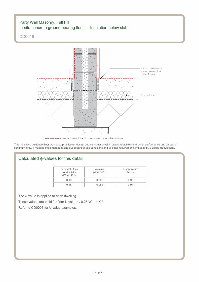
Page 66
floor insulation
dpm
denotes ‘notional’ line of continuous air barrier to be maintained
ensure continuity of airbarrier between floorand wall finish
Party Wall Masonry. Full FillIn-situ concrete ground bearing floor — Insulation below slab
CD0019
This indicative guidance illustrates good practice for design and construction with respect to achieving thermal performance and air barrier continuity only. It must be implemented taking due regard of site conditions and all other requirements imposed by Building Regulations.
Calculated �-values for this detail
Inner leaf blockconductivity(W·m–1·K–1)
�-value(W·m–1·K–1)
Temperaturefactor
0.19 0.060 0.93
0.15 0.052 0.94
The �-value is applied to each dwelling.
These values are valid for floor U value � 0.25 W·m–2·K–1.
Refer to CD0003 for U value examples.

Page 67
Notes (include details of any corrective action)
Party Wall Masonry. Full FillIn-situ concrete ground bearing floor — Insulation below slab
CD0019
Guidance checklistDate: ................................................... Site manager/supervisor: .............................................................................
Site name: .................................................................................................... Plot No: .............................................
Ref Item Yes/No Inspected (initials and date)
1 Is the edge insulation as specified? — Minimum resistance of 0.8 m2·K· W–1
(eg 20 mm of insulation with � = 0.025 W·m–1·K–1)
— Installed up to floor finish
2 Is the party wall fully filled with insulation of 0.044 W·m–1·K–1 or less?
3 Is the party wall cavity width 100 mm or less?
4 Is the party wall insulation continued at least 215 mm below underside of slab?
5 Is the floor insulation abutting the blockwork wall, leaving no gaps?
6 Are the foundations at least 215 mm deep of aircrete blocks?
7 Is the concrete floor slab 225 mm maximum (including floor finish)?
8 Is the continuity of the air barrier achieved? If not, please provide details.
Copyright is owned by Constructive Details Ltd. Copying or reproduction of the contents is not permitted without the consent of Constructive Details Ltd.
Constructive Details Ltd
Bucknalls Lane,Garston, WatfordHertfordshire WD25 9BA
t: + 44 (0)1923 665300 f: + 44 (0)1923 665301
e: [email protected] w: www.constructivedetails.co.uk
.........................................
.........................................
.........................................
.........................................
©2012
.........................................
.........................................
.........................................
.........................................
.........................................

Page 68
Party Wall Masonry. Full Fill
Roof — Insulation at ceiling level — Ventilated loft
100 mm aircrete concrete blockleaves to separating wall
full fill cavity insulationto separating wall
ceiling insulation
insulation betweenlast truss and wall
party wall cavity width
minimum 200 mm wall insulation
CD0020
Issued: 1 June 2012
Notes• party wall fully filled with insulation (� = 0.044 W·m–1·K–1 maximum)• maximum party wall cavity width of 100 mm• ceiling insulation thickness between 130 and 410 mm• maximum ceiling insulation conductivity 0.044 W·m–1·K–1
• the party wall insulation should continue to at least 200 mm above the top of the ceiling insulation• pack compressible insulation between last truss/joist and party wall to prevent any gaps between the
insulation and the wall• ensure all gaps are sealed• other improved air barrier continuity solutions can be used.
This indicative guidance illustrates good practice for design and construction with respect to achieving thermal performance and air barrier continuity only. It must be implemented taking due regard of site conditions and all other requirements imposed by Building Regulations.

Page 69
denotes ‘notional’ line of continuous air barrier to be maintained
ceiling insulation
ensure continuity of airbarrier between ceilingand wall finish
Party Wall Masonry. Full FillRoof — Insulation at ceiling level — Ventilated loft
CD0020
This indicative guidance illustrates good practice for design and construction with respect to achieving thermal performance and air barrier continuity only. It must be implemented taking due regard of site conditions and all other requirements imposed by Building Regulations.
Calculated �-values for this detail
Ceiling insulation thickness between 130 mm and 209 mm
Ceiling insulation thickness between 210 mm and 309 mm
Ceiling insulation thickness between 310 mm and 410 mm
Block conductivity (W·m–1·K–1)
�-value (W·m–1·K–1)
Temperature factor
�-value (W·m–1·K–1)
Temperature factor
�-value (W·m–1·K–1)
Temperature factor
0.19 0.087 0.90 0.065 0.93 0.049 0.90
0.15 0.077 0.91 0.055 0.94 0.041 0.91
The �-value is applied to each dwelling.
This values are valid for roof U values � 0.20 W·m–2·K–1.

Page 70
Notes (include details of any corrective action)
Party Wall Masonry. Full FillRoof — Insulation at ceiling level — Ventilated loft
CD0020
Guidance checklistDate: ................................................... Site manager/supervisor: .............................................................................
Site name: .................................................................................................... Plot No: .............................................
Ref Item Yes/No Inspected (initials and date)
1 Is the party wall fully filled with insulation of 0.044 W·m–1·K–1 or less?
2 Is the party wall cavity width 100 mm or less?
3 Is the ceiling insulation thickness between 130 and 410 mm?
4 Is the ceiling insulation conductivity 0.044 W·m–1·K–1 or less?
5 Is the gap between the last joist and the party wall filled with insulation?
6 Is the party wall insulation continued to at least 200 mm above the top of the ceiling insulation?
7 Is the continuity of the air barrier achieved? If not, please provide details.
Copyright is owned by Constructive Details Ltd. Copying or reproduction of the contents is not permitted without the consent of Constructive Details Ltd.
Constructive Details Ltd
Bucknalls Lane,Garston, WatfordHertfordshire WD25 9BA
t: + 44 (0)1923 665300 f: + 44 (0)1923 665301
e: [email protected] w: www.constructivedetails.co.uk
.........................................
.........................................
.........................................
©2012
.........................................
.........................................
.........................................
.........................................
.........................................

Page 71
Party Wall Masonry. Full Fill
Roof — Insulation at rafter level — Unventilated rafter void
100 mm aircreteconcrete block full fill cavity insulation
to separating wall
breathable roofmembrane
insulation underrafters (optional)
minimum 100 mm insulation
insulation betweenrafter and wall
party wall cavity width
CD0021
Issued: 1 June 2012
Notes• minimum 100 mm insulation on top of party wall with conductivity 0.040 W·m–1·K–1 or less covering the full
width of party wall
• fill the void between top of the wall and underside of breathable roof membrane and the gap between rafter and wall
• maximum roof insulation conductivity 0.040 W·m–1·K–1 between 150 mm minimum rafters
• ensure continuity of the insulation throughout the junction leaving no gaps
• party wall fully filled with insulation (� = 0.044 W·m–1·K–1 maximum)
• maximum party wall cavity width of 100 mm
• use a vapour control layer in the roof plasterboard if required by BS 5250 : 2011
• insulation under or above rafters (not shown in drawing) are optional
• ensure all gaps are sealed
• other improved air barrier continuity solutions can be used.
This indicative guidance illustrates good practice for design and construction with respect to achieving thermal performance and air barrier continuity only. It must be implemented taking due regard of site conditions and all other requirements imposed by Building Regulations.

Page 72
Party Wall Masonry. Full FillRoof — Insulation at rafter level — Unventilated rafter void
CD0021
This indicative guidance illustrates good practice for design and construction with respect to achieving thermal performance and air barrier continuity only. It must be implemented taking due regard of site conditions and all other requirements imposed by Building Regulations.
Calculated �-values for this detail
Inner leaf block conductivity (W·m–1·K–1)
�-value (W·m–1·K–1)
Temperature factor
0.19 0.071 0.93
0.15 0.069 0.93
The �-value is applied to each dwelling.
These values are valid for roof U values � 0.20 W·m–1·K–1.
denotes 'notional' line of continuous air barrier to be maintained
ensure continuity of air barrierbetween ceiling and wall finish
insulation between rafters
insulation underrafters (optional)

Page 73
Notes (include details of any corrective action)
Party Wall Masonry. Full FillRoof — Insulation at rafter level — Unventilated rafter void
CD0021
Guidance checklistDate: ................................................... Site manager/supervisor: .............................................................................
Site name: .................................................................................................... Plot No: .............................................
Ref Item Yes/No Inspected (initials and date)
1 Is there minimum 100 mm insulation on top of party wall with conductivity 0.040 W·m–1·K–1 or less covering the full width of party wall?
2 Is the void between top of the wall and underside of breathable roof membrane filled with insulation with conductivity 0.04 W·m–1·K–1 or less?
3 Is the gap between rafter and wall filled with insulation with conductivity 0.04 W·m–1·K–1 or less?
4 Is the roof insulation conductivity 0.040 W·m–1·K–1 or less between 150 mm minimum rafters?
5 Is the continuity of insulation throughout the junction achieved?
6 Is the party wall fully filled with insulation of 0.044 W·m–1·K–1 or less?
7 Is the party wall cavity width 100 mm or less?
8 Is the continuity of the air barrier achieved? If not, please provide details.
.........................................
.........................................
.........................................
.........................................
Copyright is owned by Constructive Details Ltd. Copying or reproduction of the contents is not permitted without the consent of Constructive Details Ltd.
Constructive Details Ltd
Bucknalls Lane,WatfordHertfordshire WD25 9BA
t: + 44 (0)1923 665300 f: + 44 (0)1923 665301
e: [email protected] w: www.constructivedetails.co.uk ©2012
.........................................
.........................................
.........................................
.........................................