Embed Size (px)
Citation preview
Teradyne Technical Interchange Meeting │ May 3-4, 2016 1
Boundary Scan using Consolidated Automated Support System (CASS) Capability
Chris Maher | NAVAIR | FRC East | [email protected] Jared Tucker | NAVAIR | FRC East | [email protected] Anthony Sparks | JTAG Technologies | [email protected]
Teradyne Technical Interchange Meeting │ May 3-4, 2016 2
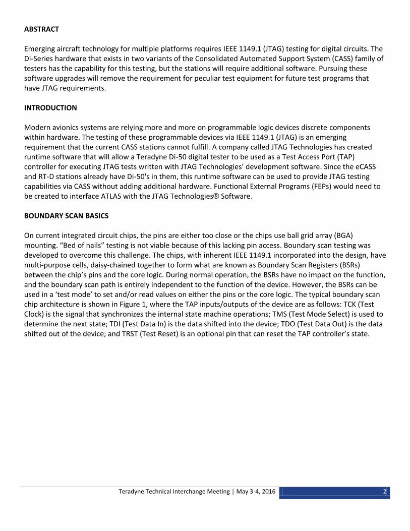
ABSTRACT Emerging aircraft technology for multiple platforms requires IEEE 1149.1 (JTAG) testing for digital circuits. The Di-Series hardware that exists in two variants of the Consolidated Automated Support System (CASS) family of testers has the capability for this testing, but the stations will require additional software. Pursuing these software upgrades will remove the requirement for peculiar test equipment for future test programs that have JTAG requirements. INTRODUCTION Modern avionics systems are relying more and more on programmable logic devices discrete components within hardware. The testing of these programmable devices via IEEE 1149.1 (JTAG) is an emerging requirement that the current CASS stations cannot fulfill. A company called JTAG Technologies has created runtime software that will allow a Teradyne Di-50 digital tester to be used as a Test Access Port (TAP) controller for executing JTAG tests written with JTAG Technologies’ development software. Since the eCASS and RT-D stations already have Di-50's in them, this runtime software can be used to provide JTAG testing capabilities via CASS without adding additional hardware. Functional External Programs (FEPs) would need to be created to interface ATLAS with the JTAG Technologies® Software. BOUNDARY SCAN BASICS On current integrated circuit chips, the pins are either too close or the chips use ball grid array (BGA) mounting. “Bed of nails” testing is not viable because of this lacking pin access. Boundary scan testing was developed to overcome this challenge. The chips, with inherent IEEE 1149.1 incorporated into the design, have multi-purpose cells, daisy-chained together to form what are known as Boundary Scan Registers (BSRs) between the chip’s pins and the core logic. During normal operation, the BSRs have no impact on the function, and the boundary scan path is entirely independent to the function of the device. However, the BSRs can be used in a ‘test mode’ to set and/or read values on either the pins or the core logic. The typical boundary scan chip architecture is shown in Figure 1, where the TAP inputs/outputs of the device are as follows: TCK (Test Clock) is the signal that synchronizes the internal state machine operations; TMS (Test Mode Select) is used to determine the next state; TDI (Test Data In) is the data shifted into the device; TDO (Test Data Out) is the data shifted out of the device; and TRST (Test Reset) is an optional pin that can reset the TAP controller’s state.
Teradyne Technical Interchange Meeting │ May 3-4, 2016 3
Figure 1: Boundary Scan Chip
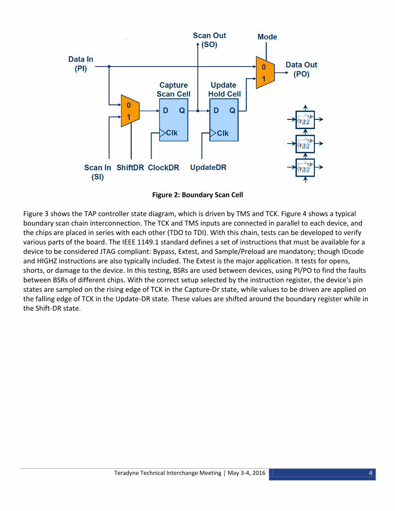
Each boundary scan chip contains an Instruction Register, a Bypass Register, an Identification Register, and Boundary Register. The Instruction Register contains the current instruction the TAP controller uses to command the device into a particular setup: which data register is used; how BSR are set up; etc. The Bypass Register is used to circumvent the current chip and test other components. The Identification Register contains important information (version number, manufacturer’s part number, etc.) to verify the correct chip is being tested. A Boundary Scan Cell, shown in Figure 2, is used to move data on the I/O pins of the device. The boundary scan cell can capture data on its parallel input (PI), update data onto its parallel output (PO), serially scan data from its scan out to a neighboring scan in, or behave transparently (passing the parallel input directly to the parallel output). These various modes of operation are determined by the Instruction Register and TAP Controller.
Teradyne Technical Interchange Meeting │ May 3-4, 2016 4
Figure 2: Boundary Scan Cell
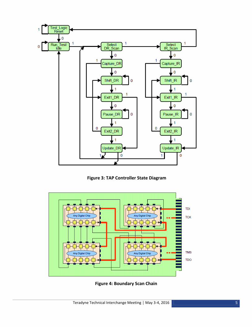
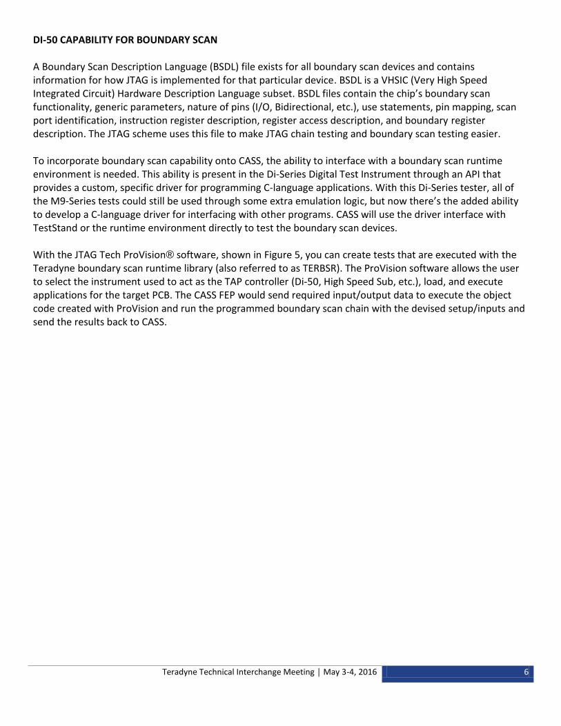
Figure 3 shows the TAP controller state diagram, which is driven by TMS and TCK. Figure 4 shows a typical boundary scan chain interconnection. The TCK and TMS inputs are connected in parallel to each device, and the chips are placed in series with each other (TDO to TDI). With this chain, tests can be developed to verify various parts of the board. The IEEE 1149.1 standard defines a set of instructions that must be available for a device to be considered JTAG compliant: Bypass, Extest, and Sample/Preload are mandatory; though IDcode and HIGHZ instructions are also typically included. The Extest is the major application. It tests for opens, shorts, or damage to the device. In this testing, BSRs are used between devices, using PI/PO to find the faults between BSRs of different chips. With the correct setup selected by the instruction register, the device's pin states are sampled on the rising edge of TCK in the Capture-Dr state, while values to be driven are applied on the falling edge of TCK in the Update-DR state. These values are shifted around the boundary register while in the Shift-DR state.
Teradyne Technical Interchange Meeting │ May 3-4, 2016 5
Figure 3: TAP Controller State Diagram
Figure 4: Boundary Scan Chain
Teradyne Technical Interchange Meeting │ May 3-4, 2016 6
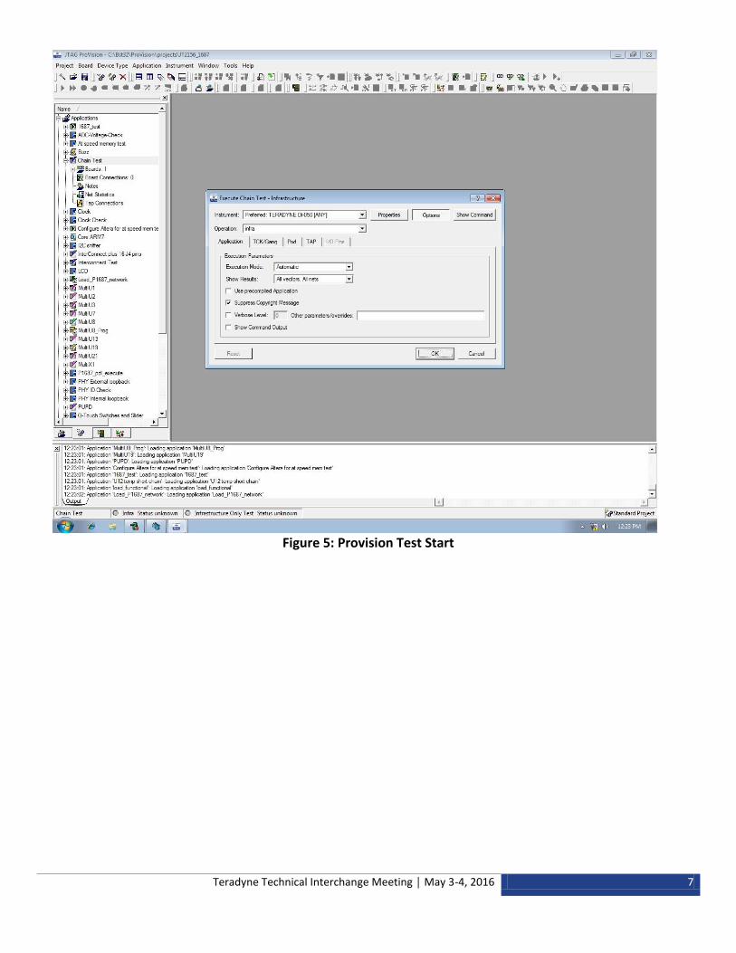
DI-50 CAPABILITY FOR BOUNDARY SCAN A Boundary Scan Description Language (BSDL) file exists for all boundary scan devices and contains information for how JTAG is implemented for that particular device. BSDL is a VHSIC (Very High Speed Integrated Circuit) Hardware Description Language subset. BSDL files contain the chip’s boundary scan functionality, generic parameters, nature of pins (I/O, Bidirectional, etc.), use statements, pin mapping, scan port identification, instruction register description, register access description, and boundary register description. The JTAG scheme uses this file to make JTAG chain testing and boundary scan testing easier. To incorporate boundary scan capability onto CASS, the ability to interface with a boundary scan runtime environment is needed. This ability is present in the Di-Series Digital Test Instrument through an API that provides a custom, specific driver for programming C-language applications. With this Di-Series tester, all of the M9-Series tests could still be used through some extra emulation logic, but now there’s the added ability to develop a C-language driver for interfacing with other programs. CASS will use the driver interface with TestStand or the runtime environment directly to test the boundary scan devices. With the JTAG Tech ProVision® software, shown in Figure 5, you can create tests that are executed with the Teradyne boundary scan runtime library (also referred to as TERBSR). The ProVision software allows the user to select the instrument used to act as the TAP controller (Di-50, High Speed Sub, etc.), load, and execute applications for the target PCB. The CASS FEP would send required input/output data to execute the object code created with ProVision and run the programmed boundary scan chain with the devised setup/inputs and send the results back to CASS.
Teradyne Technical Interchange Meeting │ May 3-4, 2016 7
Figure 5: Provision Test Start
Teradyne Technical Interchange Meeting │ May 3-4, 2016 8
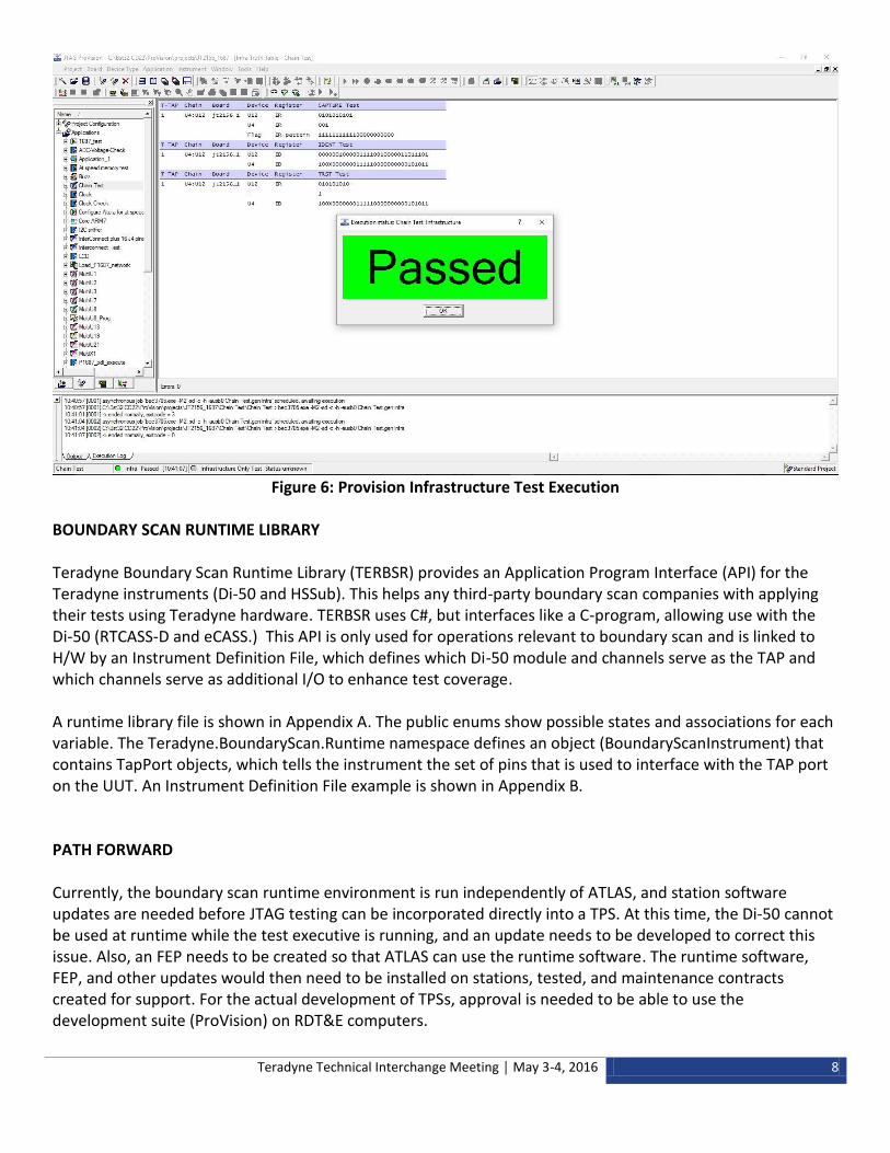
Figure 6: Provision Infrastructure Test Execution BOUNDARY SCAN RUNTIME LIBRARY Teradyne Boundary Scan Runtime Library (TERBSR) provides an Application Program Interface (API) for the Teradyne instruments (Di-50 and HSSub). This helps any third-party boundary scan companies with applying their tests using Teradyne hardware. TERBSR uses C#, but interfaces like a C-program, allowing use with the Di-50 (RTCASS-D and eCASS.) This API is only used for operations relevant to boundary scan and is linked to H/W by an Instrument Definition File, which defines which Di-50 module and channels serve as the TAP and which channels serve as additional I/O to enhance test coverage. A runtime library file is shown in Appendix A. The public enums show possible states and associations for each variable. The Teradyne.BoundaryScan.Runtime namespace defines an object (BoundaryScanInstrument) that contains TapPort objects, which tells the instrument the set of pins that is used to interface with the TAP port on the UUT. An Instrument Definition File example is shown in Appendix B. PATH FORWARD Currently, the boundary scan runtime environment is run independently of ATLAS, and station software updates are needed before JTAG testing can be incorporated directly into a TPS. At this time, the Di-50 cannot be used at runtime while the test executive is running, and an update needs to be developed to correct this issue. Also, an FEP needs to be created so that ATLAS can use the runtime software. The runtime software, FEP, and other updates would then need to be installed on stations, tested, and maintenance contracts created for support. For the actual development of TPSs, approval is needed to be able to use the development suite (ProVision) on RDT&E computers.
Teradyne Technical Interchange Meeting │ May 3-4, 2016 9
REFERENCES 1. Board-level testing and IEEE1149.x Boundary Scan standard, Artur Jutman, February 2011. 2. Boundary Scan Tutorial, Dr R. G. Bennetts, September 2002 3. Di-Series Digital Test Instrument version 4.4, Revision A, Teradyne, September 2015. 4. CASS Change Request 2381, Timothy Davis, February 2016.
Teradyne Technical Interchange Meeting │ May 3-4, 2016 10
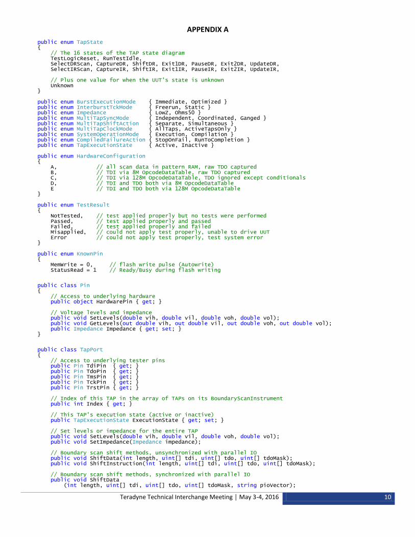
APPENDIX A public enum TapState { // The 16 states of the TAP state diagram TestLogicReset, RunTestIdle, SelectDRScan, CaptureDR, ShiftDR, Exit1DR, PauseDR, Exit2DR, UpdateDR, SelectIRScan, CaptureIR, ShiftIR, Exit1IR, PauseIR, Exit2IR, UpdateIR, // Plus one value for when the UUT's state is unknown Unknown } public enum BurstExecutionMode { Immediate, Optimized } public enum InterburstTckMode { Freerun, Static } public enum Impedance { LowZ, Ohms50 } public enum MultiTapSyncMode { Independent, Coordinated, Ganged } public enum MultiTapShiftAction { Separate, Simultaneous } public enum MultiTapClockMode { AllTaps, ActiveTapsOnly } public enum SystemOperationMode { Execution, Compilation } public enum CompiledFailureAction { StopOnFail, RunToCompletion } public enum TapExecutionState { Active, Inactive } public enum HardwareConfiguration { A, // all scan data in pattern RAM, raw TDO captured B, // TDI via 8M OpcodeDataTable, raw TDO captured C, // TDI via 128M OpcodeDataTable, TDO ignored except conditionals D, // TDI and TDO both via 8M OpcodeDataTable E // TDI and TDO both via 128M OpcodeDataTable } public enum TestResult { NotTested, // test applied properly but no tests were performed Passed, // test applied properly and passed Failed, // test applied properly and failed Misapplied, // could not apply test properly, unable to drive UUT Error // could not apply test properly, test system error } public enum KnownPin { MemWrite = 0, // flash write pulse (Autowrite) StatusRead = 1 // Ready/Busy during flash writing
public class Pin { // Access to underlying hardware public object HardwarePin { get; } // Voltage levels and impedance public void SetLevels(double vih, double vil, double voh, double vol); public void GetLevels(out double vih, out double vil, out double voh, out double vol); public Impedance Impedance { get; set; } }
public class TapPort { // Access to underlying tester pins public Pin TdiPin { get; } public Pin TdoPin { get; } public Pin TmsPin { get; } public Pin TckPin { get; } public Pin TrstPin { get; } // Index of this TAP in the array of TAPs on its BoundaryScanInstrument public int Index { get; } // This TAP's execution state (active or inactive) public TapExecutionState ExecutionState { get; set; } // Set levels or impedance for the entire TAP public void SetLevels(double vih, double vil, double voh, double vol); public void SetImpedance(Impedance impedance); // Boundary scan shift methods, unsynchronized with parallel IO public void ShiftData(int length, uint[] tdi, uint[] tdo, uint[] tdoMask); public void ShiftInstruction(int length, uint[] tdi, uint[] tdo, uint[] tdoMask); // Boundary scan shift methods, synchronized with parallel IO public void ShiftData (int length, uint[] tdi, uint[] tdo, uint[] tdoMask, string pioVector);
Teradyne Technical Interchange Meeting │ May 3-4, 2016 11
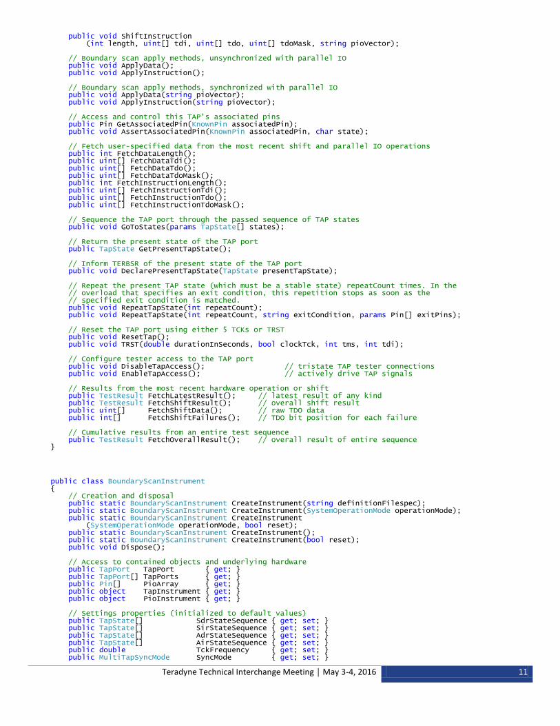
public void ShiftInstruction (int length, uint[] tdi, uint[] tdo, uint[] tdoMask, string pioVector); // Boundary scan apply methods, unsynchronized with parallel IO public void ApplyData(); public void ApplyInstruction(); // Boundary scan apply methods, synchronized with parallel IO public void ApplyData(string pioVector); public void ApplyInstruction(string pioVector); // Access and control this TAP's associated pins public Pin GetAssociatedPin(KnownPin associatedPin); public void AssertAssociatedPin(KnownPin associatedPin, char state); // Fetch user-specified data from the most recent shift and parallel IO operations public int FetchDataLength(); public uint[] FetchDataTdi(); public uint[] FetchDataTdo(); public uint[] FetchDataTdoMask(); public int FetchInstructionLength(); public uint[] FetchInstructionTdi(); public uint[] FetchInstructionTdo(); public uint[] FetchInstructionTdoMask(); // Sequence the TAP port through the passed sequence of TAP states public void GoToStates(params TapState[] states); // Return the present state of the TAP port public TapState GetPresentTapState(); // Inform TERBSR of the present state of the TAP port public void DeclarePresentTapState(TapState presentTapState); // Repeat the present TAP state (which must be a stable state) repeatCount times. In the // overload that specifies an exit condition, this repetition stops as soon as the // specified exit condition is matched. public void RepeatTapState(int repeatCount); public void RepeatTapState(int repeatCount, string exitCondition, params Pin[] exitPins); // Reset the TAP port using either 5 TCKs or TRST public void ResetTap(); public void TRST(double durationInSeconds, bool clockTck, int tms, int tdi); // Configure tester access to the TAP port public void DisableTapAccess(); // tristate TAP tester connections public void EnableTapAccess(); // actively drive TAP signals // Results from the most recent hardware operation or shift public TestResult FetchLatestResult(); // latest result of any kind public TestResult FetchShiftResult(); // overall shift result public uint[] FetchShiftData(); // raw TDO data public int[] FetchShiftFailures(); // TDO bit position for each failure // Cumulative results from an entire test sequence public TestResult FetchOverallResult(); // overall result of entire sequence }
public class BoundaryScanInstrument { // Creation and disposal public static BoundaryScanInstrument CreateInstrument(string definitionFilespec); public static BoundaryScanInstrument CreateInstrument(SystemOperationMode operationMode); public static BoundaryScanInstrument CreateInstrument (SystemOperationMode operationMode, bool reset); public static BoundaryScanInstrument CreateInstrument(); public static BoundaryScanInstrument CreateInstrument(bool reset); public void Dispose(); // Access to contained objects and underlying hardware public TapPort TapPort { get; } public TapPort[] TapPorts { get; } public Pin[] PioArray { get; } public object TapInstrument { get; } public object PioInstrument { get; } // Settings properties (initialized to default values) public TapState[] SdrStateSequence { get; set; } public TapState[] SirStateSequence { get; set; } public TapState[] AdrStateSequence { get; set; } public TapState[] AirStateSequence { get; set; } public double TckFrequency { get; set; } public MultiTapSyncMode SyncMode { get; set; }
Teradyne Technical Interchange Meeting │ May 3-4, 2016 12
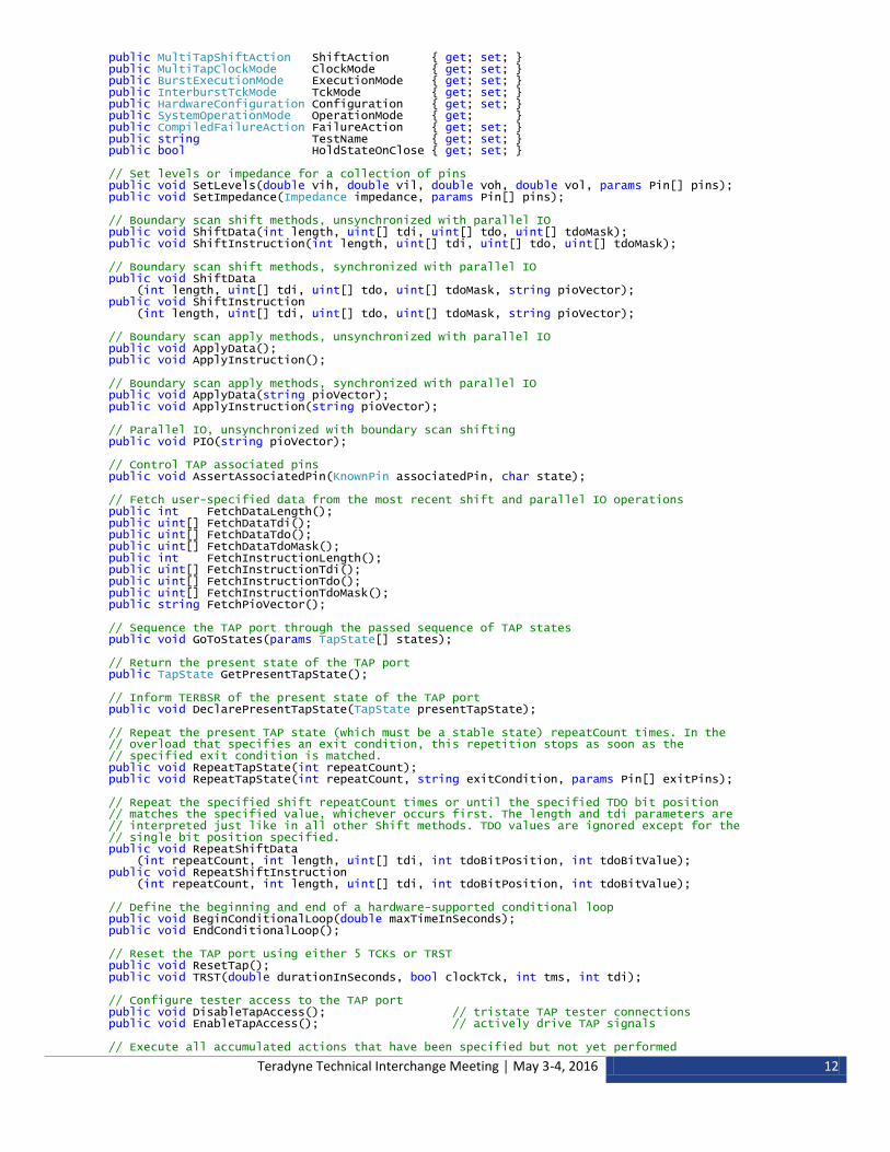
public MultiTapShiftAction ShiftAction { get; set; } public MultiTapClockMode ClockMode { get; set; } public BurstExecutionMode ExecutionMode { get; set; } public InterburstTckMode TckMode { get; set; } public HardwareConfiguration Configuration { get; set; } public SystemOperationMode OperationMode { get; } public CompiledFailureAction FailureAction { get; set; } public string TestName { get; set; } public bool HoldStateOnClose { get; set; } // Set levels or impedance for a collection of pins public void SetLevels(double vih, double vil, double voh, double vol, params Pin[] pins); public void SetImpedance(Impedance impedance, params Pin[] pins); // Boundary scan shift methods, unsynchronized with parallel IO public void ShiftData(int length, uint[] tdi, uint[] tdo, uint[] tdoMask); public void ShiftInstruction(int length, uint[] tdi, uint[] tdo, uint[] tdoMask); // Boundary scan shift methods, synchronized with parallel IO public void ShiftData (int length, uint[] tdi, uint[] tdo, uint[] tdoMask, string pioVector); public void ShiftInstruction (int length, uint[] tdi, uint[] tdo, uint[] tdoMask, string pioVector); // Boundary scan apply methods, unsynchronized with parallel IO public void ApplyData(); public void ApplyInstruction(); // Boundary scan apply methods, synchronized with parallel IO public void ApplyData(string pioVector); public void ApplyInstruction(string pioVector); // Parallel IO, unsynchronized with boundary scan shifting public void PIO(string pioVector); // Control TAP associated pins public void AssertAssociatedPin(KnownPin associatedPin, char state); // Fetch user-specified data from the most recent shift and parallel IO operations public int FetchDataLength(); public uint[] FetchDataTdi(); public uint[] FetchDataTdo(); public uint[] FetchDataTdoMask(); public int FetchInstructionLength(); public uint[] FetchInstructionTdi(); public uint[] FetchInstructionTdo(); public uint[] FetchInstructionTdoMask(); public string FetchPioVector(); // Sequence the TAP port through the passed sequence of TAP states public void GoToStates(params TapState[] states); // Return the present state of the TAP port public TapState GetPresentTapState(); // Inform TERBSR of the present state of the TAP port public void DeclarePresentTapState(TapState presentTapState); // Repeat the present TAP state (which must be a stable state) repeatCount times. In the // overload that specifies an exit condition, this repetition stops as soon as the // specified exit condition is matched. public void RepeatTapState(int repeatCount); public void RepeatTapState(int repeatCount, string exitCondition, params Pin[] exitPins); // Repeat the specified shift repeatCount times or until the specified TDO bit position // matches the specified value, whichever occurs first. The length and tdi parameters are // interpreted just like in all other Shift methods. TDO values are ignored except for the // single bit position specified. public void RepeatShiftData (int repeatCount, int length, uint[] tdi, int tdoBitPosition, int tdoBitValue); public void RepeatShiftInstruction (int repeatCount, int length, uint[] tdi, int tdoBitPosition, int tdoBitValue); // Define the beginning and end of a hardware-supported conditional loop public void BeginConditionalLoop(double maxTimeInSeconds); public void EndConditionalLoop(); // Reset the TAP port using either 5 TCKs or TRST public void ResetTap(); public void TRST(double durationInSeconds, bool clockTck, int tms, int tdi); // Configure tester access to the TAP port public void DisableTapAccess(); // tristate TAP tester connections public void EnableTapAccess(); // actively drive TAP signals // Execute all accumulated actions that have been specified but not yet performed
Teradyne Technical Interchange Meeting │ May 3-4, 2016 13
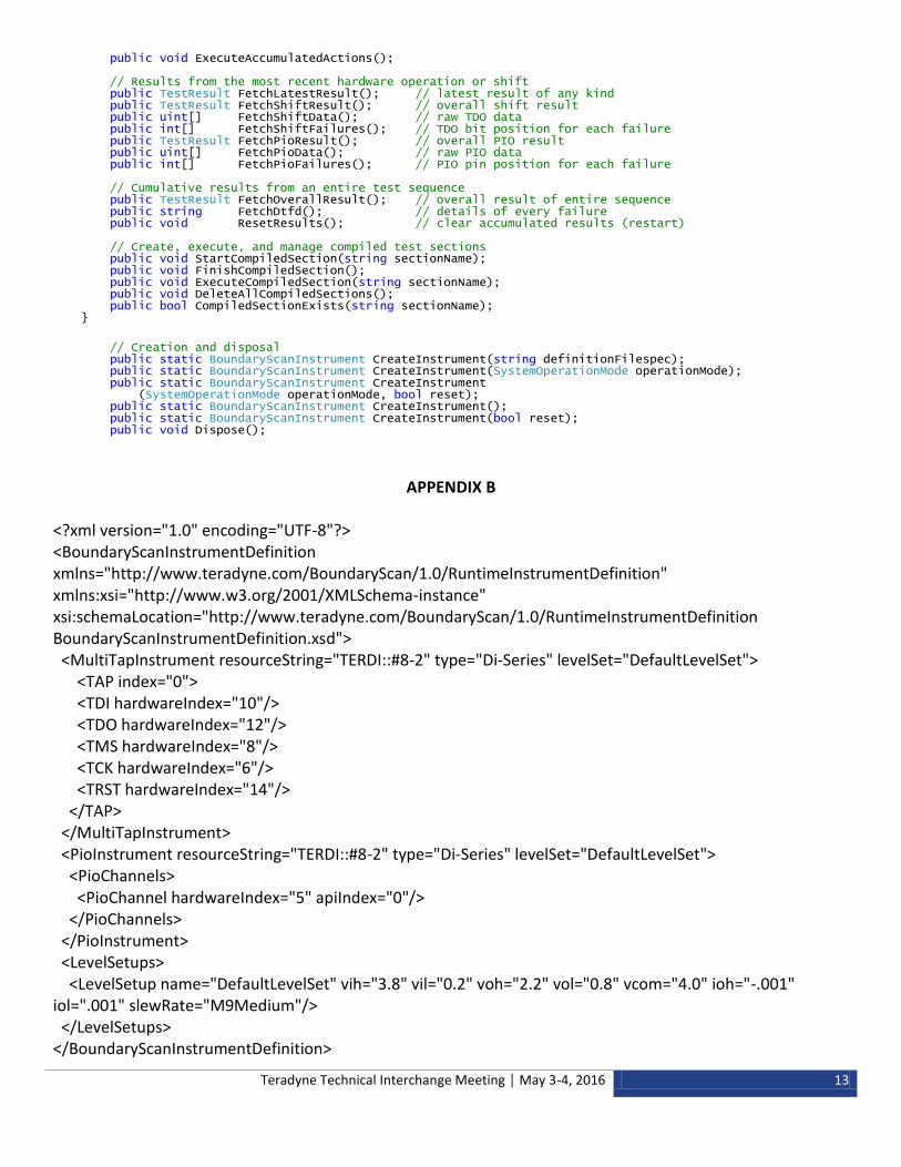
public void ExecuteAccumulatedActions(); // Results from the most recent hardware operation or shift public TestResult FetchLatestResult(); // latest result of any kind public TestResult FetchShiftResult(); // overall shift result public uint[] FetchShiftData(); // raw TDO data public int[] FetchShiftFailures(); // TDO bit position for each failure public TestResult FetchPioResult(); // overall PIO result public uint[] FetchPioData(); // raw PIO data public int[] FetchPioFailures(); // PIO pin position for each failure // Cumulative results from an entire test sequence public TestResult FetchOverallResult(); // overall result of entire sequence public string FetchDtfd(); // details of every failure public void ResetResults(); // clear accumulated results (restart) // Create, execute, and manage compiled test sections public void StartCompiledSection(string sectionName); public void FinishCompiledSection(); public void ExecuteCompiledSection(string sectionName); public void DeleteAllCompiledSections(); public bool CompiledSectionExists(string sectionName); }
// Creation and disposal public static BoundaryScanInstrument CreateInstrument(string definitionFilespec); public static BoundaryScanInstrument CreateInstrument(SystemOperationMode operationMode); public static BoundaryScanInstrument CreateInstrument (SystemOperationMode operationMode, bool reset); public static BoundaryScanInstrument CreateInstrument(); public static BoundaryScanInstrument CreateInstrument(bool reset); public void Dispose();
APPENDIX B
<?xml version="1.0" encoding="UTF-8"?> <BoundaryScanInstrumentDefinition xmlns="http://www.teradyne.com/BoundaryScan/1.0/RuntimeInstrumentDefinition" xmlns:xsi="http://www.w3.org/2001/XMLSchema-instance" xsi:schemaLocation="http://www.teradyne.com/BoundaryScan/1.0/RuntimeInstrumentDefinition BoundaryScanInstrumentDefinition.xsd"> <MultiTapInstrument resourceString="TERDI::#8-2" type="Di-Series" levelSet="DefaultLevelSet"> <TAP index="0"> <TDI hardwareIndex="10"/> <TDO hardwareIndex="12"/> <TMS hardwareIndex="8"/> <TCK hardwareIndex="6"/> <TRST hardwareIndex="14"/> </TAP> </MultiTapInstrument> <PioInstrument resourceString="TERDI::#8-2" type="Di-Series" levelSet="DefaultLevelSet"> <PioChannels> <PioChannel hardwareIndex="5" apiIndex="0"/> </PioChannels> </PioInstrument> <LevelSetups> <LevelSetup name="DefaultLevelSet" vih="3.8" vil="0.2" voh="2.2" vol="0.8" vcom="4.0" ioh="-.001" iol=".001" slewRate="M9Medium"/> </LevelSetups> </BoundaryScanInstrumentDefinition>


![[Kenneth P. Parker] the Boundary-Scan Handbook](https://img.pdfslide.net/doc/110x75/56d6bd711a28ab30168e01e2/kenneth-p-parker-the-boundary-scan-handbook.jpg)