Embed Size (px)
Citation preview

R. & M. No. 3060(18~573)
A.R.C. Technical Report
MINISTRY OF SUPPLY
AERONAUTICAL RESEARCH COUNCIL
REPORTS AND MEMORANDA
Calculation of Derivatives
for a Cropped Delta Wing withSubsonic Leading Edges Oscillating
in a Supersonic Air StreamBy
J. WATSON, B.Sc., B.A.,
of the Aerodynamics Division, N.P.L.
Crown Copyright Reserved
LONDON: HER MAJESTY'S STATIONERY OFFICE
1958
TWELVE SHILLINGS NET

Calculation of Derivatives for a Cropped Delta Wingwith Subsonic Leading Edges Oscillating
in a Supersonic 'Air StreamBy
J. WATSON, B.Sc., B.A"of the Aerodynamics Division, N.P.L.
Reports and Memoranda No. 3060*
July) 1956
Summary.-The lift, pitching moment and full-span constant-chord control hinge-moment are derived for a croppeddelta wing describing harmonic plunging and pitching oscillations of small amplitude and low-frequency parameter ina supersonic air stream. It is assumed that (a) the wing has subsonic leading edges, (b) the wing is sufficiently thinand the Mach number sufficiently supersonic to permit the use of linearised theory.
Expressions for the various derivative coefficients are obtained for a particular delta wing of aspect ratio I ·8 andtaper ratio 1/7; these are avaluated and tabulated for Mach numbers I· I, 1· 15, 1,2, I '3, I ·4, I '5, I ·6 and 1·944.
1. I ntroduction.-This report considers theoretical derivatives of lift, pitching moment andhinge moment corresponding to slow plunging and pitching oscillations of a cropped delta wingwith subsonic leading edges. Values of these derivatives are determined for comparison withexperimental data to be obtained at supersonic speeds. Measurements of the oscillatory derivatives for a wing of aspect ratio 1· 8 and taper ratio 1/7 with a full-span constant-chord flap(Fig. 1) are in progress at the National Physical Laboratory for Mach numbers up to 111 = 1·8.
In a previous paper the author' (1955) determines theoretical derivatives for a cropped deltawing with constant-chord flap, when the flap alone is oscillating. In conjunction with Ref. 1,the present theory yields approximate expressions for the complete set of theoretical derivativesfor low-frequency longitudinal oscillations of the wing-flap combination.
In a supersonic air stream the loading on part of a thin plane cropped delta wing of the planform shown in Fig. 1 is identically that on the complete triangular wing performing the samemotion. Over the remaining part of the wing the velocity potential has been calculated byEvvards" (1950) method (section 3).
Formulae for the aerodynamic coefficients and derivatives are obtained in section 4; theaccuracy of the results is discussed in section 5.
2. General Supersonic Theory.-The governing equation and the boundary condition are madenon-dimensional and, under the assumption of simple harmonic motion, a transformation is madewhich, for low frequency, reduces the unsteady problem to a steady one at the particular Machnumber -yl2 (e.g., Watson' (1955) ).
2.1. Governing Equation.-The perturbation velocity potential, 9, satisfies
a29 a29 2a29 2( a29 a29 (29)at2+ 2U axat + U ax2= a ax2+ ay2 + az2 ,
where a = velocity of sound, U = velocity of air stream.
* Published with permission of the Director, National Physical Laboratory.
1
(2.1)

--- --- - - -- -- -- -- -------
Non-dimensional space and time variables X, Y, Z, T are introduced by
x = cj3X
y = cY(2.2)
z = cZ
t = cTjU
where lYI = U]a, /1 = y(M2-- 1), c= mean chord of wing. In accordance with the assumption
of simple harmonic motion, eP is proportional to eiQJ t = eivT and a time-independent complexperturbation-velocity potential.on, is given by
where v = wcjU. Equations (2.3) and (2.2) transform (2.1) to
a2(jj a2(jj a2(jj M 2v2
aY2 + aZ2 - aX 2 = M2 - 1 (jj.
Since v 2 is being neglected, equation (2.4) becomes
which corresponds to steady motion at Mach number Y2.
(2.3)
(2.4)
(2.5)
2.2. Boundary Condition over the Wing.~Under the assumptions of linearised theory the wingmay be treated as a flat plate and the conditions over the wing (Fig. 1) may be referred to theplane z, 0 so that the' transformed' wing in XYZ-space (Fig. 3) may also be treated as aflat plate and the conditions over the wing referred to the plane Z = O.
1t is only necessary to consider pitching oscillations of the wing, plunging motion being theparticular case when the axis of oscillation is at infinity. Let the wing oscillate about the axisx = ch, z- 0 with complex angle of incidence o; == rt.o ei QJ t = rt.o e", where rt.o is a constantamplitude. Then the complex displacement of points on the wing above the plane z = 0 isgiven by (Fig. 2)
~ = rt.(he - x) = rt.o eiQJ t (he - x). (2.6)
The boundary condition is that the flow is tangential over the wing, so that under the approximations of linearised theory the upwash on the wing
( aeP ) = (dC) = (a~ + UaC)az z ~ (I dt z ~ (I dt ax z ~ (I
= - rt.U{(l - ivh) + ivj3X},
2

since w = vUle and x = e{JX. From this result the upwash on the transformed wing is given by
W = (~~)z=o = e(a~t=o = e(~~)z=o exp {- «r + iV({J + ~)X}
= - ~oeU[(1 - ivh) + iV(2{J + ~)XJon neglecting squares of v. Thus the upwash on the transformed wing may be written in theform
(2.7)
where WI = - ~oeU(l - ivh) and W 2 = - qX, where q = iv~oeU {2{J + (1/f3)}. Since WI is aconstant, it may be regarded as the upwash when the transformed wing is at a constant incidenceand since W 2 = - qX, where q is a constant, W 2 may be regarded as the upwash on the transformed wing when it is pitching about the axis X = Z = °with a constant angular velocity q.The condition W = WI will be called the uniform incidence case and W = W 2 the uniform pitchingcase, both being governed by (2.5), the quasi-steady equation corresponding to M = V2.
Let rfJ(X, Y) denote the value of rfJ at the point (X, Y) on the upper surface of the wing and(arfJl aXL ~O the corresponding value of arfJl ax; on the lower surface of the wing, rfJ = - rfJ(X, Y)and arfJ/ax = - (arfJ/aX)z=o.
The pressure difference across the wing in the positive z-direction or the lift per unit area is
( af af)P = 2po -;;-t + U Ta aX z = 0
Since terms of order v2 are being neglected the lift per unit area may be written as
p = 2po_U eil'T [{ 1 - iV(f3 + !)X}( arfJ) - i.!:. »ix, Y)J.{Jc 13 ax Z = 0 (J
It is convenient to introduce the non-dimensional loading function, F, defined by
F = Pef3I(2poU e;,'T) ,
so that, from (2.8)
F = {I - iV(f3 + ~)X}(:~)z=o - ~ rfJ(X, V).
(2.8)
(2.9)
(2.10)
When F has been determined over the transformed wing the aerodynamic coefficients are foundas follows: because of the symmetry about Y = 0, the complex lift coefficient is
L 2e2{Jff P dX dYC A + B + C = 2e{J fJ' P dX dY
L = tPou2S tPou2 2se POU 2s A +B+C
= 4eil'Tff
F dX dY;Us A+B+C
3
(2.11)

the complex pitching-moment coefficient about the axis through the apex is
= - 2CfJ2 fJ XP dX dYPou2sJ A+B+C
= - 4fJ eiVYJJ XF dX dY .US A+B+C '
the complex hinge-moment coefficient about x = cho is
= _ 4(j ei,·Y (~)2II (X _ ho) F dX dYUs c} B+C (j
(2.12)
4fJ ei"Y II ~ 4eiVTII ]US A X F dX dY + hoCL - h; Us A F dX dY . (2.13)
The suffices of the integral signs refer to the areas of integration (Fig. 3),
.c'1 denoting the area 0
15 denoting the area X o
C denoting the area X 0
X
X
Y
(2.14)
where XI = Co/(1C. Xu c-= (co - C})/(1C and m, = fis/(co - cf ) .
It is assumed that the Mach lines from the tips of the leading edges do not intersect on thewing and that the wing has subsonic leading edges, so that
(2.15)which is equivalent to
(2.16)
For most practical cropped delta plan-forms the restriction imposed by the lower limit of M isunimportant; for the particular wing of aspect ratio 1·8 and taper ratio 1/7, being tested at theN.P.L., equation (2.16) gives the condition 1·038 ]\if 1·944.
~). Velocity Poteniial.: Let WI be the solution of equation (2.5) subject to the boundarycondition (aWl/ az)zco =c WI (the uniform incidence case) and q)2 the solution of equation (2.5)
4

subject to the boundary condition (2I:]J2! 2Z)z~o = W2 (the uniform pitching case). Then
I:]J = I:]Jl + 1:]J2 (3.1)
is the solution of (2.5) subject to (2.7). Non-dimensional loading functions F 1 , F 2 are defined by
and F 2 = {I - i'V(iJ + !)X} (2I:]J2). -- ~ (/>2(X, Y),fI 2X z~o f3
so that, by (2.10) and (3.1)
F = F 1 + F 2•
(3.2)
(3.4)
(3.5)
Expressions for I:]Jl(X, Y) and F 1 are derived in section 3.1 and those for 1:]J2(X, 1') and F 2 insection 3.2. Because of the symmetry about the plane Y = 0, only the region Y ?:'o Ois considered.Under the condition (2.15) the flow in regions A and B (Fig. 3) is the same as that over the infinitetriangular wing formed by producing the leading edges downstream; there are known solutionsfor the velocity potential of an infinite triangular wing with subsonic leading edges at uniformincidence or with uniform pitching (Ref. 3), so that I:]Jl(X, Y) and 1:]J2(X, Y) are known in regionsA and B. The potentials <P1(X , Y) and 1:]J2(X, Y) in region C are found by Evvard's method inthe case of steady flow at Mach number yl2 (Ref. 2, equation (29) ).
3.1. Velocity Potential for Uniform I ncidence.-Since the flow in regions A and B is the sameas that over the infinite triangular wing with subsonic leading edges Y = ± mIX, then in thoseregions I:]Jl(X, Y) is the perturbation-velocity potential on the triangular wing at a uniformincidence - WI/U in a stream with Mach number yl2. This perturbation-velocity potentialis known (Ref. 3, p. 302, equation (148) ); in the present notation
(2I:]J1) W1m12X
2X z=o = - E(k)(mI2X2 _ Y 2)1/2'
where E(k) is the complete elliptic integral of the second kind with modulus k = (1 - mI2)1/2.From (3.5) it follows that
rr. (X Y) __ WI ( 2X2 _ Y 2)1/2'4'1 , - E(k) m1 , (3.6)
since I:]Jl(X, Y) is zero on Y = mIX. From (3.2), (3.5) and (3.6), the loading function in regionsA and B
(3.7)
(3.8)
In region C, Evvard's method for steady flow at M = yl2 (Ref. 2, equation (29)) givesI:]Jl(X, Y) as a double integral over a rectangular region of the type 51 '+ 52 (Fig. 4), namely,
(~)z~o drodso
(r - ro)I/2 (s - soY/2 ,
5

where rv2 = (X - Y) )
sy2 =-= (X + Y)(3.9)
In the region S2 on the plan-form the upwash (01\/ oZ)z~o equals WI (equation (2.7) ), so that(3.8) may be written in the form
n 1 Jf (~i)z~odrodso- WI cfJ1(X , Y) = W
1y 2 JSI (r _ r
o) I / 2 (s _ SO)I/2 + C(X, Y), (3.10)
where
'(X Y) 1 Jf dr; dsoC ,. = ~2 '( _ )1/2 ( _ )1/2V .52 r ro s So
This repeated integral is easily evaluated and by use of (3.9) we obtain
C(X Y) = 2(m1X + Y) (sinh -1 U1/2 _1_ u,1/2 (1 _I- U)I/2}, (1 -- mI
2) 1/2 \ , (3.11)
where(1 - m1) (mlXo - Y)
U = (mIX + Y)(~).12)
If the leading edges of the wing are produced downstream so as to form an infinite triangularwing, then the flow in SI remains unaffected and is precisely that investigated by Behrbohrri'(1952). The upwash outboard of an infinite triangular wing at uniform incidence with subsonicleading edges Y = ± mIX, as quoted in equation (12a) of Ref. 4, should read
_. (XU en { ~ It) I(1 - t)2)1/2}lVo - - E(k) E(9, k) -- (
rj2 _ m/)1/2
so that, in the present notation
where E(9, k) is the incomplete elliptic integral of the second kind with modulus k = (1 - m I2)1/2
and argument ¢ = sin :' [{(X2 - Y 2)1/2}/kX ]. In region Sj, Y/X is negative so that
Y(X2 _ Y2) 1/2 }
X(y2 - mI2X 2)1/2 . (3.13)
This upwash is a function of Y/X only or, by (3.9), a function of (s - r)/(s + r) only. Let
So - Yo'V==--
So + r o •(3.14)
Then, in terms of current co-ordinates, the upwash is a function of v only and may be writtenin the form
(0(/)1) _ _ WI L(v)oZ z~o - E(k)
6
(3.15)

where
and
(3.16)
It is convenient to change the variables of integration in the integral (3.10) from (ro, so) to (ro, »).Then from (3.15), equation (3.10) becomes
where
(3.17)
(3.18)
The integral I does not appear to be integrable in terms of known functions. Accordingly,since the integrand of I is positive in 51' the term (s - SO)-1/2 in the integrand of I is expandedin the form
(3.19)
and term-by-term integration gives successive approximations to I. Only the first two termsof this expansion are retained, as the effect on (/Jl(X, Y) of omitting the remaining terms is ingeneral small. Thus equation (3.18) becomes
where
and, from (3.14),
I = II + 12 , ••
I - (~)1/2ff roL(v) drodv1 - S 81 (1 - V)2 (r - ro) I / 2
(3.20)
(3.21)
(3.22)
In terms of (ro,v), the region 51 is defined by (Fig. 4) s - mlXov2 ~ 1'0 ~ r, - 1 ~ v ~ - m,so that (3.21) becomes
_ (2)1/2JY ro dr; J->1l1 L(v) dvII - S s m1X o'/2 (r - ro) I /2 -1 (1 - V)2 •
The integration with respect to r« is easily performed and it is found that
Jy ro dro - 2 ( X . /2)1/2 (2 X • / )( _ )1/2 - 3- r - s + ml ov r + s - ml ov 2
s -mlXo-VZ r Yo
(3.23)
(3.24)
by (3.9). The other integral in (3.23), where L(v) is given by (3.16), is an elliptic integral whose
7

value is
J- IIl t L(v) dv 1-1 (1 _ V)2 = k2 {m1E(k) - (1 - 1?2)K(k)},
where K(k) is the complete elliptic integral of the first kind of modulus k = (1 - m I2)1/2.
(3.25)
By (~~.9) the factor (2/S)I/2 equals 23/4/(X + Y)1/2, so that (3.24) and (3.25) reduce (3.23) to
11 = 2~2 h{m1E(k) - (1 - k2)K(k)} (m:+~yYY/2 (3X - Y - 2m1XO) ' (3.26)
Similarly, equation (3.22) may be written in-the form
1 Jr r o2 dr; I-lilt (1 + v) L(v) dv
12 = 21 / 2S 3 / 2 • " (r - r )1/2 (1 - V)3 ,s - m1.xo" 2 0 - 1
where
(3.27)
and
21 / 2S3/2 (X + Y)3/2 .
From (3.28), (3.29) and (3.30), equation (3.27) becomes
J2 = y~ 1~ [{4 - 3k2 - (1 - m 1)2 - m1k2}E(k) - 2(2 - 3k2 + k4)K(k)J X
(3.30)
Finally from (3.20), (3.26) and (3.31), the velocity potential w1(X , Y) from (3.17) may bewritten in the form
- ;1 w1(X , Y) = C(X, Y) - 2i 1(m1)(mf+-17Y/2 (3X - Y - 2m1XO)
? (' ) (mIX O - Y)I/2 (I5X2 _ IOvy- ...i 2 m, (X + Y)3/2 A
where C(X, Y) is given by (3.11),
\/2 1i 1(m1) = 3"" k2E(k) {m1E(k) - (1 - k2)K(k)}
8
(3.33)

and
Differentiation of (3.32) with respect to X yields
n (a$l) _ 2m1 . h :' 1/2 () (m1XO- Y)1/2 (3X 7Y 2 X)- WI ax Z~O -- (1 _ m12)1/2 SIll U - il m, (X + Y)3/2 + + m1 0
(X Y)1/2- i 2(m1) ~x+-Y)5/2 (15X 2+ 70XY - 41Y2 -+ 20m1XOX
- 28m1XOY - 36m12X02) , (3.35)
where u is defined by (3.12). The loading function, FlJ in region C is given by (3.2) (3.32) and(3.35), namely,
n F _ { . ( l)X} [ 2m1 . h:' 1/2- WI 1 -- 1 - tv fJ + ~ (1 _ m1
2Y/2SIll u --
(m1XO- Y)1/2-- i 1(m1) (X + Y)3/2 (3X + 7Y + 2m1XO) -
( ) (mlXO - Y)1/2 (15X2.J. 70XY 41 'IT2 20 X X- i 2m1 (X + Y)5/2 ;- -.1 + m; 0 -
- 28m1XOY - 36m 12X
o2)J
- ~ [C(X, Y) - 2il(m1) (mf+_yYY/2 (3X - Y - 2m1XO)
2 ( ) (mlXO - Y)1/2 (15X 2 lOX 'IT '""'172 20 X X- i 2m, (X + Y)3/2 -.1 + J.1 - m1 0 -
(3.36)
where u, C(X, Y), i 1(m1), i 2(m1) are defined by equations (3.12), (3.11), (3.33) and (3.34) respectively.
3.2. Velocity Potential for Uniform Pitching.-The derivation of the velocity potential in thiscase is similar to that performed in section 3.1. Here the perturbation-velocity potential$2(X, Y) on the triangular wing with subsonic leading edges, Y = ± mIX, has to satisfy thesteady condition W = W2 = - qX in a stream of Mach number v2. By Ref. 3, p. 334,
where1 - 2m 2 m 2
e(m1 ) = 1 .~ E(k) + 1 1 2 K(k);- m1 - m1
9
(3.37)
(3.38)

this represents the perturbation-velocity potential in regions A and B.that
I t follows from (3.37)
(3.39)
Thus from (3.3), (3.37) and (3.39) we obtain the loading function F 2 in regions A and B. Sinceq is proportional to v and terms of order v 2 are being neglected, then the loading function may bewritten in the form
so that, in regions A and 13,
(3.40)
As in section 3.1, Evvard's method in the case of steady flow at Mach number \/2 (Ref. 1,equation (29) ) is used to calculate c{>2(X, Y) in region C. Thus (/)2(X, Y) is given by (3.8) with (/>1
replaced by c{>2; since ((j1>2! (j Z)z ~ () = W 2== - qX over 52' it follows that
((j(/)2)
1 II,.,z - dr o ds;
0: (/) (X Y) - _ __ 0 Z - 0 D (X Y)q 2, - qy2 81 (r - r o)1/2 (s - SO)1/2 + "
where
(So + ro) d d1_ 1 II y2 r
oSO
D(X, ) )- . /2 . (r _ r )1/2 (s _ S )1/2V oS. 0 0
_ 1 IY dr; JS (so + Yo) d- ., 1 2 1 2 So·
2 S-1Il1Xo"2(r-rO) / yo(l-nll ) (S - SO) /1+1111
This integral is easily evaluated and by use of (3.9) we obtain
(3.41)
where zz is defined by (3.12).
The upwash outboard of a uniformly pitching infinite triangular wing at A1by Behrbohm (Ref. 4, equation (12) ) should read
(3.42)
v2 as quoted
for m, < 1171 :(; 1,
so that, in the present notation
10

(
(j(J) ) qx {1 - 2m 2 m 2 Iy: (X2- Y 2)1 /2 )
az2
Z=o . - e(m1) 1 _ m1~ E(¢, k) + 1 _lm/ F(¢, k) - X(~2 _ m12X2)1/2f
for m, < IY jX I < 1,
where F(¢, k) is the incomplete elliptic integral of the second kind with modulus k =. (1 - m12)1/2and argument ¢ = sin:' [{(X2 - Y 2)1/2}jkX]. Since YjX is negative in 51' then in that region
(aC/>2) _ qX f 1 - 2m1
2
':lZ - - -(-) \ 1 _ 2 E(¢, k)U z « 0 e m 1 l m 1
(~l43)
which in terms of the current co-ordinates (ro, v) (equations (3.9) and (3.14) ) may be written as
where
( aC/>2) = y2az Z=t)
(for - 1 < v < - m1) , (3.44)
and
(3.45)
By changing the variables of integration in the integral of (3.41) from (ro, so) to (rO! v), and bymaking use of (3.44), we have
:n; ]- C/>2(X, Y) = - -(-) + D(X, Y),q e m, (3.46)
where (3.47)
It can readily be shown that the integrand of] is positive within 51' As in section 3.1, anapproximation to ] is obtained by replacing the term (s - so) -1/2 in the integrand of ] by thefirst two terms in the expansion (3.19). Thus (3.47) becomes
where
and, since So =-: ro (1 + v)j(l - v) by (3.14),
] = .l, fj' r 03 M(v) (1 + v) dro dv
2 53/ 2 81 (1 - V)3 (r - r o) 1 / 2 .
...
(3.48)
(3.49)
(3.50)
As for the corresponding integrals in section 3.1, (3.49), (3.50) may be written as a product oftwo integrals. Thus (3.49) becomes
(3.51)

where the first integral is given by (3.28) and the second integral, where 1\;1(v) is given by (3.45),is an elliptic integral whose value is
where
alm1) = 30k~fml) [{k2(2 - k2) (1 - m1)2 (1 - 2k2)}E(k)
- {2k2 + (1 - m1 ) 2 } (1 - k2)K(k)J .
(3.52)
(3.53)
By (3.9) the factor 2/51/2 equals 25/4/(X + Y)1/2, so that (~l28) and (3.52) reduce (3.51) to
II == 2e(m1)a1(m1 ) (m;+-yyr/2
(15X 2- 10XY + 7Y2
- 20m1XOX - 4m1XOY
Similarly, equation (3.50) may be written in the form
~~~ _1 Jr Yo3 dr; r: (1 + v) l\IJ(v) dv
I 2 -~ 3/2 , ( ) 1/2 (1) 3 '5 s-m,Xo"2 Y - Yo -1 - V
where
(3.54)
(3.55)
and
where
a2(m1 ) = 420~e~ml) [{k2(32 - 34k2 -+- 3k4) + (1 - m1)2 (4 - 4m1 - 3k2
) X
X (1 - 2k2)}E(k) - {2k2(16 - 9k2) + (1 - m1)2 (4 -- 4m1 - 3k2
) } X
X (1 - k2)K(k)],
and
I 23 / 4
5 3 / 2 - (X + Y)3/2 .
(3.57)
(3.58)
(3.59)
From (3.56), (3.57) and (3.59), equation (3.55) becomes
12 = 2e(m1)a2(m1 ) ((:~~y~~:/2 (35X3 - 35X2Y + 49Xya- 9Y3
- 70m1XOX2
- 28m1XOXY - 22m1XOY2+ 84m1
2Xo2X + 36m12X
o2y - 40m13X
o3) . (3.60)
12
Finally from (3.48), (3.54) and (3.60), the velocity potential if>2(X, Y) from (3.46) may bewritten in the form
~ if>2(X, Y) = D(X, Y) - 201(m1) (mr+_yYY/2 (15X2 - lOXY + 7Y2 - 20m1XOX
- 4m1XOY + 12m12Xo
2) - 202(m1) (~r+_y~~:/2 (35X3 - 35X2Y
(3.6] )
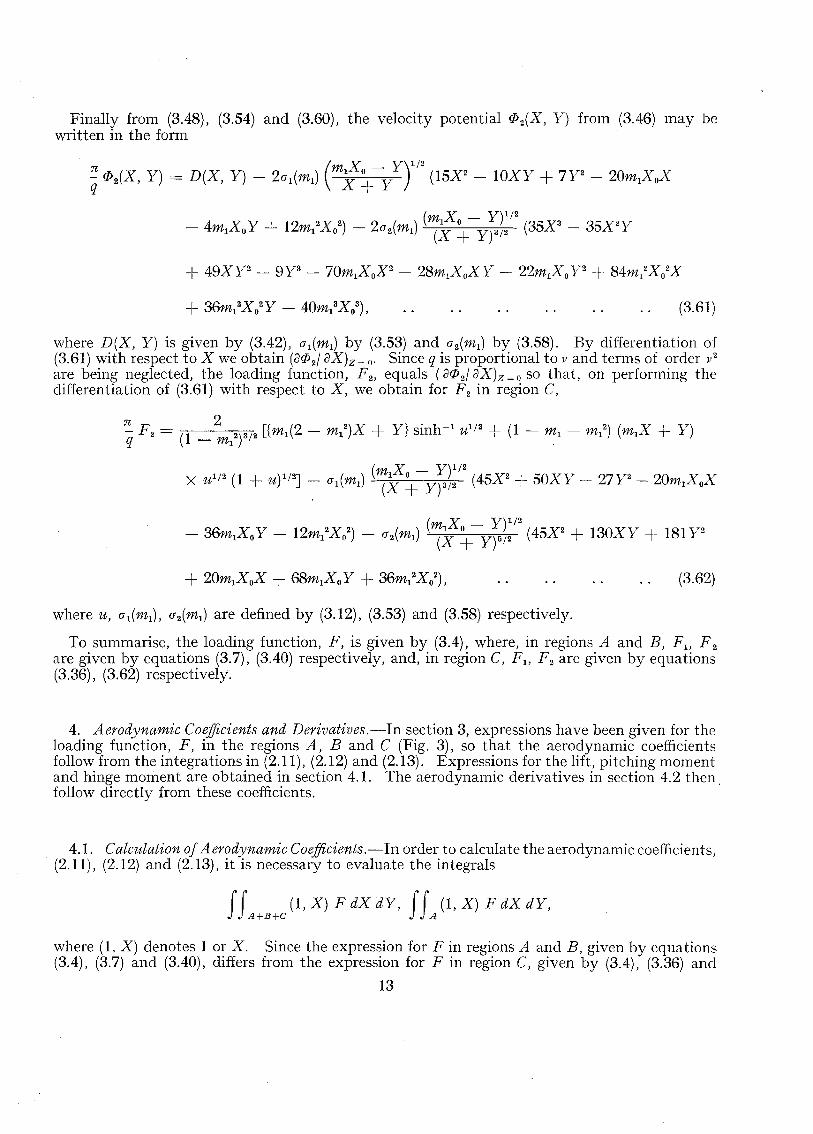
where D(X, Y) is given by (3.42), 01(m1) by (3.53) and o2(m1) by (3.58). By differentiation of(3.61) with respect to X we obtain (Oif>2! oX)z= o- Since q is proportional to v and terms of order v"are being neglected, the loading function, F 2, equals (Oif>2! oX)z ~ 0 so that, on performing thedifferentiation of (3.61) with respect to X, we obtain for F 2 in region C,
~ F - 2 [f (2 _ 2)X Yj si h-1 1/2 .i, (1 _ _ 2) (X Y)2 - (1 2)3/2 lm1 m, + SIn u I m, m-: m, +.q - m,
X Ul/2 (1 + U)I/2J - a (m) (m1XO - Y)I/2 (45X2 + 50XY - 27Y2- 20m X X1 1 (X + Y)3/2 1 0
(3.62)
where U, ol(m1), o2(m1) are defined by (3.12), (3.53) and (3.58) respectively.
To summarise, the loading function, F, is given by (3.4), where, in regions A and B, F 1 , F 2
are given by equations (3.7), (3.40) respectively, and, in region C, F lJ F 2 are given by equations(3.36), (3.62) respectively.
4. Aerodynamic Coefficients and Derivatives.-In section 3, expressions have been given for theloading function, F, in the regions A, Band C (Fig. 3), so that the aerodynamic coefficientsfollow from the integrations in (2.11), (2.12) and (2.13). Expressions for the lift, pitching momentand hinge moment are obtained in section 4.1. The aerodynamic derivatives in section 4.2 then.follow directly from these coefficients.
4.1. Calculation of Aerodynamic Coefficients.-In order to calculate the aerodynamic coefficients,(2.11), (2.12) and (2.13), it is necessary to evaluate the integrals
JJ (1, X) F dX dY, JJ (1, X) F dX dY,A+B+C A
where (1, X) denotes 1 or X. Since the expression for F in regions A and B, given by equations(3.4), (3.7) and (3.40), differs from the expression for F in region C, given by (3.4), (3.36) and
13
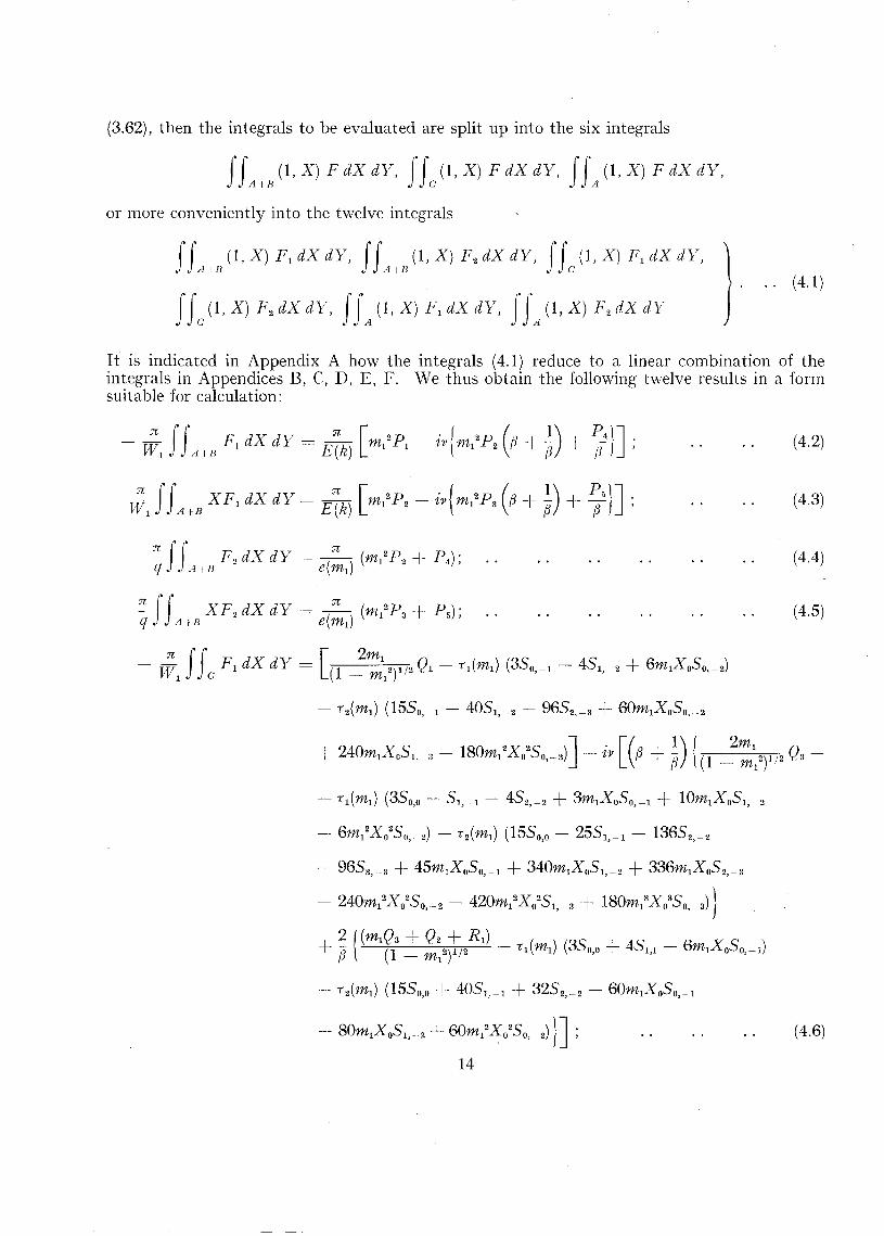
(3.62), then the integrals to be evaluated are split up into the six integrals
f fA+B (1, X) F dX dY, f fe (1, X) F dX dY, JJA (1, X) F dX dY,
or more conveniently into the twelve integrals
JfAllJ(l,X) r.sx sv, JfAH(l,X) F 2 dX dY , ffe(l,X) F l dX dY ,
JJe (1, X) F 2 dX dY, JJA(1, X) t: dX dY, JfA(1, X) F 2 dX dY) .. (4.1)
It is indicated in Appendix A how the integrals (4.1) reduce to a linear combination of theintegrals in Appendices B, C, D, E, F. We thus obtain the following twelve results in a formsuitable for calculation:
n fJ' F dX «v - n [2p . f 2p (-WI AIR'I 1-- E (k) m, I- t l' tm 1 2fJ (4.2)
- T;1 JJe r. dX dY = L1 !:::12)1/2 o. - i l (ml ) (350, _ 1 - 45 1, - 2 -+- 6ml X 050, __ 2)
- i 2(ml ) (1550, 1 - 405 1, _2 - 9652, _ 3 -+- 60ml X050, _2
(4.3)
(4.4)
(4.5)
- i l (m l ) (350,0 - 5 1, - 1 - 452, 2 -+- 3ml X050, _ 1 -+- lOm1X051, - 2
- 6mI2X0250,2) - i 2(m l ) (1550,0 - 255 1, __1 - 13652, _ 2
- 9653, 3 -+- 45mlX050, _ 1 -+- 340ml X 051, _ 2 -l- 336mlX052,_3
- 240m/X0250,_2 - 420mI2X0251,_3 -+- 180mI3X0350,_3)}
2{(mlQ3-+-Q2-+-Rl) r )-+- ~ (1 _ mI2)1/2 - i l (m l ) (350,0 -+- 45 1,1 - 6m1X 050, - 1
- i 2(m 1) (1550,0 -+- 405 1, _ 1 + 3252, _ 2 - 60m lX050,_1
-- 80m1X051,_2 60mI2~0250'_2)}];
14
(4.6)

(4.7)
15
(4.8)

(4.9)
(4.10)
(4.11)
(4.12)
(4.13)
In these equations WI and q are given by (2.7), e(ml), il(ml), i2(ml), O'l(ml), 0'2(ml) are defined by(3.38), (3.33), (3.34), (3.53), (3.58) respectively and the P's, Q's, R's, S's and T's are given inAppendices B, C, D, E and F respectively.
It is convenient to express the right-hand sides of equations (4.2), (4.3) ... (4.13) in the forms
respectively, so that the equations may he written in the form
J'J' F[ «x «v =-c -- WI {R r(4.2) - ivRJ4.2)},A+B n
j'I XFI «x cv =c - WI {Rr(4.3) - ivR;(4.3)},A!-E at
(4.14)
(4.15)
I f F2 dX dY• A I TJ
(4.16)
II XF2 sx sv = fj Rr(4.5),A+E n
IIe F I dX sv =c. - V~l {R r(4.6) - ivl?;(4.6)},
16
(4.17)
(4.18)

IIe XF1dX dY = - ~l {Rr(4.7) - ivR i(4.7)}, ..
II F2 dX dY = qRr(4.8),e n
II XF2 dX dY = CJ.. Rr(4.9),e n
f fA X F 1dX dY = - :1 {R r(4.11) - ivR;(4.11)},
f fA X F 2dX dY = ~ Rr(4.13),
since to the first order in frequency F 2 is real.
(4.19)
(4.20)
(4.21)
(4.22)
(4.23)
(4.24)
(4.25)
Then from equations (2.11), (3.4) and (4.14) . 'e' (4.25), the complex lift coefficient becomes
4 e;pT [ WI ( . )= Us - -;;- {R r(4.2) + K(4.6)} - ~v{R;(4.2) + R;(4.6)}
+ ! {R r(4.4) + Rr(4.8)}] .
Similarly the complex pitching-moment coefficient, (2.12), becomes
4;3 e;pT [ WI ( . )Cm = - US - -; {R r(4.3) + Rr(4.7)} - ~v{R;(4.3) + R;(4.7)}
+ ~ {Rr(4.5) + Rr(4.9)}] .
The complex hinge-moment coefficient, (2.13), becomes
(C)2 [ 4;3 eM ( WI . q)CH = - Cm + hOCL + -U - - {R ..(4.11) - ~vRi(4.11)} + - Rr(4.13)o s n n
ho 4 e;vT ( W I ' q)]- Us - -;;- {R r(4.1O) - ~vRi(4.1O)} + ;Rr (4.12)
17
(4.26)
(4.27)
(4.28)

After substituting for WI and q from (2.7) and discarding terms in v2 we obtain the complex liftcoefficient in the form
C. 4C~) [oc (Ry(4.2) +R(4.6)) - (~)({R;(4.2) R i(4.6) hRy(4.2)
-1- hRy(4.6)} -- (2(-; +- D{R y(4.4) R,.(4.8)})] , (4.29)
where OC oeivT has been replaced by oc and ivocoeirT by ((iC/U), where (i = doc/dt. Similarly thecomplex pitching-moment and hinge-moment coefficients become
c,/I-- -- 4(1 C~) [o: ( R y ( 4.3) +- R r ( 4.7)) - (~~) ({ Ri (4.3) +- Ri ( 4.7) hRy ( 4.3)
+- hRy(4.7)} - (2(3 +- ~) {R y(4.5) + Ry(4.9)})] ,
CH c=c (£Y [Cm + hoC I. -1- 4 C~) (oc{(1Ry(4.11) - hoRr(4.1O)}
- (~~){f3Ri(4.11) + f3 hRy(4.11) - f3(2ii DRy(4.13) - hoRi (4.1O)
-- lzohRy(4.10) +- ho(2fi ~)~?y(4.12) })] .
(4.30)
(4.31)
4.2. Calculation of Aerodynamic Derinaiioes.> Each aerodynamic coefficient may be splituniquely into two parts, viz.,
c -- .i:» -- 2' ee)1
t, ~Zo.OC Z" U
'). Cie) (4.32)(CmL 21117,!'l. f l ,
.~111." t.
Jel/ 2h7,oc (de)+ 2h" U
where (i= dct./dt and the real coefficients, Z7,' Z", m; m.; h7,' h, are the required derivatives.
The moment in the second equation of (4.32) will be taken about the axis of oscillation of thewin~ (x he) so that the moment coefficient (C"J" =c Cm +- hCL, where Cm is taken about thepitchiru; axis through the apex of the wing. Then equations (4.32) may be written
(4.33)
18
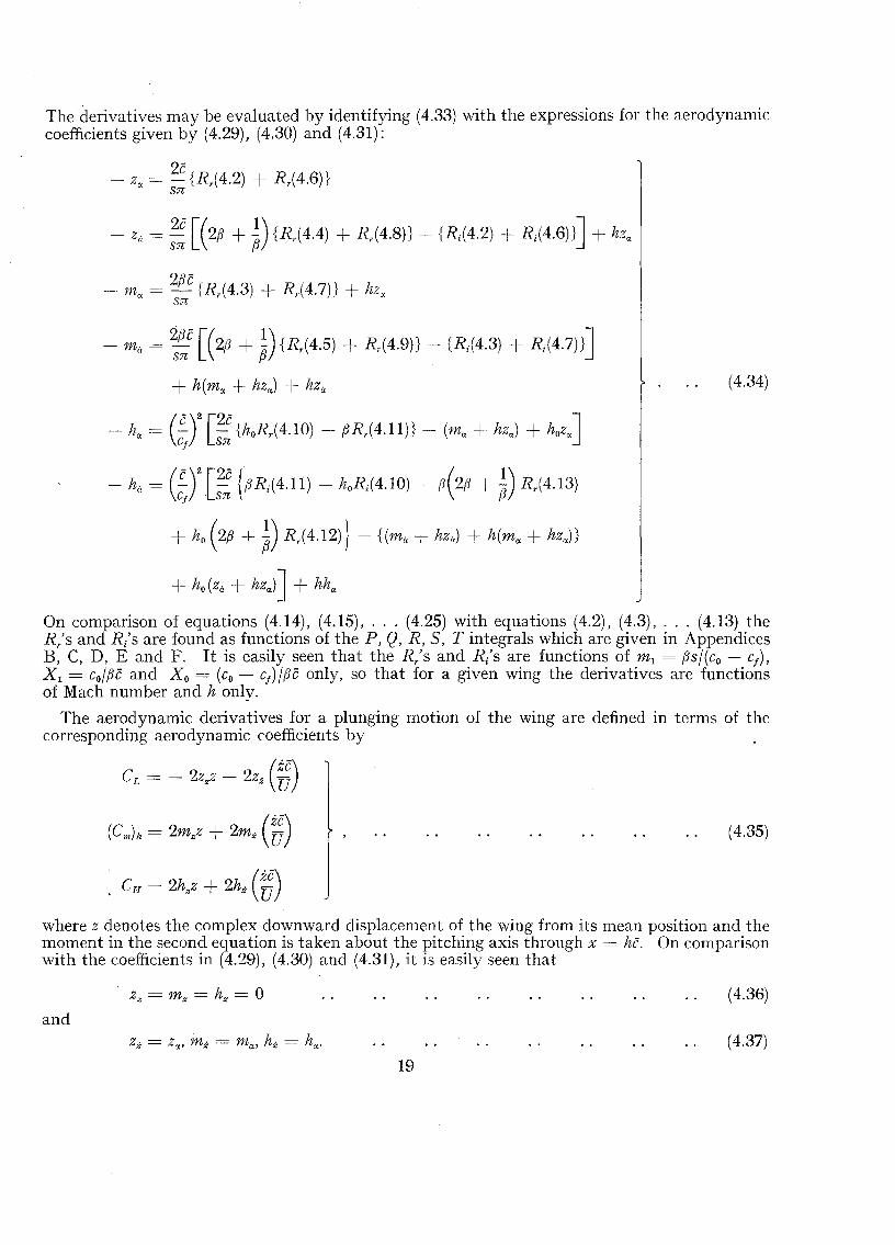
The derivatives may be evaluated by identifying (4.33) with the expressions for the aerodynamiccoefficients given by (4.29), (4.30) and (4.31):
- z; = 2c {R r(4.2) + Rr(4.6)}Sn
- z" = ;: [(213 + ~) {Rr(4.4) + Rr(4.8)} - {Ri(4.2) + Ri(4.6)}] + hzrt,
'Jf3 -- m; = ~ {Rr(4.3) + Rr(4.7)} + hz;
Sn
- mil = %e [(213 + ~) {Rr(4.5) + Rr(4.9)} - {Ri(4.3) + Ri(4.7)}]
+ h(mrt, + hzrt,) + liz;
- hrt, = (~)2 [2C {hoRr(4.1O) - f3Rr(4.11)} - im, -+ hzrt,) + hozrt,]cj sr:
(4.34)
- h" = (£y[:: {f3Ri(4.11) - hoRi(4.1O) -- fJ(2(3 + ~) Rr(4.13)
+ ho(2(3 +~) R,.(4.12)} - {(mil + hzi!) + h(mrt, + hzrt,)}
+ ho(z" + hZrt,)] + hhrt,
On comparison of equations (4.14), (4.15), ... (4.25) with equations (4.2), (4.3), ... (4.13) theR/s and R/s are found as functions of the P, Q, R, 5, T integrals which are given in AppendicesB, C, D, E and F. It is easily seen that the R/s and R/s are functions of m, = (3s/(co - Cj ) ,
X, = co/fJc and Xo = (co - cj)/f3c only, so that for a given wing the derivatives are functionsof Mach number and h onlv.
The aerodynamic derivatives for a plunging motion of the wing are defined in terms of thecorresponding aerodynamic coefficients by
(C11lh = 2mzz + 2mz (~)
. CH = 2hzz + 2hz (~)
t.j
(4.35)
where z denotes the complex downward displacement of the wing from its mean position and themoment in the second equation is taken about the pitching axis through x = he. On comparisonwith the coefficients in (4.29), (4.30) and (4.31), it is easily seen that
and
Zz = m; = hz = 0
19
(4.36)
(4.37)

It will be remembered that the derivatives (4.34) are given approximately only, because anapproximation was made in calculating the loading over region C (section 4). This approximation was the replacement of the term (s - SO)-1/2 in the integrands of (3.18) and (3.47) by thefirst two terms on the right-hand side of (3.19). However, (3.18) and (3.47) in general make onlya small contribution to the loading in region C and consequently to the derivatives in (4.34).It can readily be shown from (3.33), (3.34), (3.53), (3.58) that T1(m1), (J1(m1) are of order1~2= 1 -- m1
2 and that T2(m1), (J2(m1) are of order h4 as m, -+- 1. Thus we may consider thefollowing three approximations:
(a) A first ap proximaiio« to the derivatives is obtained by omitting the contributionsarising from (3.18) and (3.47) (this is equivalent to formally putting T 1(m1), T 2(m1),
(Jl(m1), 0'2(m1) zero in (4.34) )
(b) A second approximation is obtained by retaining only the first term in the right-handside of (3.19) in place of the term (s - SO)-1/2 (this is equivalent to formally puttingT2(m1), and 0'2(m 1) zero in (4.34) )
(c) A third approximation is obtained by retaining only the first two terms in the right-handside of (3.19) (this is equivalent to (4.34) as it stands).
Furthermore, the contribution arising from (3.18) and (3.47) is the contribution arising fromregion S1 (Fig. 4). Consequently, as the subsonic leading edges of the wing approach sonicleading edges, this contribution tends to zero, so that, as the Mach number increases, the abovethree approximations tend to each other and to the exact value.
For the particular wing of aspect ratio 1· 8 and taper ratio 1/7, the derivatives - z",-·z,;, ... - h,; are tabulated in Table 1 for the special pitching axis h = 0, and the values ofthese derivatives for any given pitching axis then follow from (4.34).
5. Discussion of Results.-Of the three types of approximation defined at the end of section 4.2,the second approximations to the derivatives in (4.34) and (4.38) for the pitching axis at the apexof the wing (h= 0) are tabulated against Mach number for a cropped delta wing (Fig. 1) of aspectratio 1·8 and taper ratio 1/7. For most practical cropped delta plan-forms this second approximation is sufficient. In Table 1 the third approximations to the derivatives are given for theMach number M cc= 1·1; even at this unfavourably low Mach number, they are seen to differlittle from the second approximation. The derivatives for pitching axes other than that throughthe apex can be found from (4.34) and (4.38).
The first and second approximations to the derivatives for the pitching axes given by he", .~
and h cc= 1 are plotted for this wing against Mach number and shown in Figs. 5,6,7,8. The thirdapproximations for M =,c 1·1, are also shown. It is seen from these figures that the derivativesare given sufficiently accurately by their first approximations for a Mach-number range fromabout i11 =: 1·3 to J11 =: 1·944 at which the leading edges are sonic. From]\;J = 1·1 to 1·3the derivatives are seen to be given sufficiently accurately by their second approximations.The quasi-steady values of - z; and - m; for 111 = 1 from Mangler's" (1955) theory are shownin Figs. 5 and 6 for comparison.
6. Achnowledgement.--The computation, the results of which are given m the table andfigures. was carried out by Miss S. W. Skan.
20

a
A, B,C
Cf
em
1(m1)
E(k), K(k)
E(ep, k), F(ep, k)
F
r; F 2
hc
hoc
hex' ha
hz, hz
H
k -
L
L(v)
m1
mex, m;
LIST OF SYMBOLS
Speed of sound
Areas of integration (Fig. 3)
Root chord
Control chordtip chord
Mean chordt(co + cf )
Complex hinge-moment coefficientH/iP oU25rcf
Complex lift coefficientL/tPoU
25
Complex pitching-moment coefficientJI/iP oU25c
Defined by equation (3.38)
Complete elliptic integrals of the first and second kinds withmodulus 1~
Corresponding incomplete elliptic integrals of argument
. -1 (X2 _ Y2)1/2ep = sm kX
Complex non-dimensional loading (equation (2.9) )
Complex non-dimensional loading for constant incidence, pitch case(equations (3.2) and (3.3) )
Streamwise distance from apex to axis of oscillation
Streamwise distance from apex to hinge line (co - cf )
Stiffness, damping derivative 'of hinge moment due to pitching(equation (4.32) )
Stiffness, damping derivative of hinge moment due to plunging(equation (4.35) )
Complex hinge moment
(1 - m12)1/ 2
Complex lift
Function obtainable from equation (3.16)
Non-dimensional tangent of semi-apex angle (see Fig. 3)(Js/(co - cf )
Direct stiffness, damping derivative of pitching moment (equation(4.32) )
21

1'Vr
Af(v)
Jt
p
q
91' .. ·95(r, s)
(r0, so)
»; R 2
Rr(4.2), Rr(4.13)
I'R;(4.2), vRi (4.1 3)
s
5
r
1',,···1'5
U
v
w
LIST OF SYMBOLS-continued
Stiffness, damping derivative of pitching moment due to plunging(equation (4.35) )
Mach number of free stream
Uja
Function obtainable from equation (3.45)
Complex pitching moment about pitching axis through apex (nose up)
Complex pressure difference across wing(equation (2.8) )
Integrals evaluated in Appendix 13
iV[e<i cU( 2(1 +-~)
Integrals evaluated in Appendix C
Axes parallel to Mach lines (equation (3.9) ) (Fig. 4)
Variables of integration in (r, s)-plane
Integrals evaluated in Appendix D
Real parts of right-hand sides of equations (4.2), ... (4.13)
Imaginary parts of right-hand sides of equations (4.2), ... (4.13)
Semi-span of wing
Surface area of wing2sc
Surface area of full-span flap2scf
Integrals evaluated in Appendix E
Areas of integration shown in Fig. 4
Time
Non-dimensional timeUtlcIntegrals evaluated in Appendix F
Function defined by equation (3.12)
Speed of free stream
(equation (3.14) ) Variable of integration
Complex upward component of velocity( (j(l>IaZ)/.o 0
Complex upward component of velocity associated with constantincidence, pitch case
22

X, y, z
x, Y,Z
fJ
v
Po
a1(mi ) , a 2(mi )
ri(mi), r 2(mi)
fjJ
([J(X, Y)
w
No. Author1 J. Watson
2 J. C. Evvard
3 S. Goldstein(editor)
4 H. Behrbohm
5 K. W. Mangler
LIST OF SYMBOLS-continued
Rectangular Cartesian co-ordinates defined by Fig. 1.
Non-dimensional co-ordinates defined by equation (2.2)
Non ..dimensionallengths shown in Fig. 3(co - cl )/fJc, co/fJc
Stiffness, damping derivative of lift due to pitching (equation(4.32) )
Stiffness, damping derivative of lift due to plunging (equation(4.35) )
Complex angle of incidence1X0 eiwt
Complex upward displacement (see Fig. 2)
Frequency parameter based on mean chordwcjU
Density of free stream
Functions defined by equations (3.53), (3.58)
Functions defined by equations (3.33), (3.34)
Perturbation-velocity potential
Time-independent complex perturbation-velocity potential on uppersurface of wing
Corresponding perturbation-velocity potential for uniform incidence
Corresponding perturbation-velocity potential for uniform pitching
2n (frequency of oscillation of wing)
REFERENCESTitle, etc.
Calculation of derivatives for a cropped delta wing with an oscillatingconstant-chord flap in a supersonic air stream. R. & M. 3059. November,1955.
Use of source distributions for evaluating theoretical aerodynamics of thinfinite wings at supersonic speeds. N.A.C.A. Report 951. 1950.
Modern developments in fluid dyanmics. High speed flow. Vol. 1, pp. 302and 334. 1953.
The flat triangular wing with subsonic leading edges in steady pitch androll at supersonic velocities. S.A.A.B. Tech. Note 9, pp. 15 and 16.1952.
Calculation of the pressure distribution over a wing at sonic speeds.R. & M. 2888. September, 1951.
23

APPENDIX A
I ntegrals required in section 4.1
In order to calculate the aerodynamic coefficients the integrals (4.1) must be evaluated. Thefirst four integrals in (4.]), namely, the integrals of F b F 2, XF1, XF2 over the region A + B,where F 1 , F 2 are given by (3.7) and (3.40), reduce to a linear combination of the integrals
JJAtB (ml;;X_d~2r/2' where X takes the forms X, X 2, X3, (m12X2 - Y 2) and X(m1
2X2 - Y 2).
The values of these integrals are given in Appendix B as P b P 2, ••• P 5• The next four integralsin (4.1), namely, the integrals of FI! F 2, XF b XF2 over region C, where F 1 , F2 are given by(3.36) and (3.62), reduce to a linear combination of three sets of integrals:
rr, x-v- sinh I UI
/2dX dY, where (m, n) take the values (0, 0), (0, 1), (1,0), (1, 1), (2,0);
• • c
Y)U I/
2 (1
5 =J'J (m X - Y)(2m+l)/2 (X + Y)(2n+l l/2 dX iv~ 111,12 1 0 ,
c
where u. is defined in equation (3.]2). The first set of integrals may be found from Appendix Cas QI' Q2' ... Q5' the integrals R 1 and R 2 are given in Appendix D and the integrals Sm,n inAppendix E. Finally, the last four integrals in (4.]) correspond to the first four integrals in (4.1)integrated over region A in place of region A + B; these are given in Appendix F asTI! T 2 , ••• T 5 •
APPENDIX B
Integrals PI! P 2, ... P 5
These are readily evaluated by writing the double integral over the region A -j B in Fig. 3as the sum of two repeated integrals
J r dX dY = JXO(l +mll-' XI dyJXI dX + J"'IXO dYJ'XO(l + ml) - Y dX.• A +B 0 Y!nzl Xo(l + 1111) - XI Y!ml
Then, if
(1 + m )1/2
+ J. 1 X 2 {COS·-1 11 _ 11(1 _ 'I1 2)1 / 2} .2 (1 _ m
1)3/20 'f 'f 'f ,
24
(B. 1)
(B.2)

(B.3)
+ 2i~1+-m~:;72/2 X o4[3(2 + 3m1
2)COS-
11} - {l6m1 + (2 7 mI
2)1)
- 16m11)2 + (4 + 2mI2)1)3} (1 - 1)2)1/2J; (B.4)
[ I f )2 X I2
} ]X 1 - m1
2 (I - (1 - m« Xo2 ;
APPENDIX C
(B.S)
(B.6)
Integrals Ql' Q2' ... Q5
The integrals over the region C in Fig. 3 are evaluated by expressing the double integrals asrepeated integrals
II Inl l X O IXIdXdY = dY dX
C Xo(l + nil) - XI Xo(l + "'1) - Y
and then reducing them to a combination of subsidiary single Integrals which are listed at theend of this Appendix. In terms of u = {(I - m1) (mIXO - Y)}!(mIX + Y),
Ql = JJc sinh --1 U1/2dX dY = 2m1(1 - m1)2(Xo + X 1)2Ia(2) - (1 ~:nl) X o2j3(2), (C.1)
2S

fJ' ,x sinh I U}f2dX dY = - ~ Q2• C ml .
_ ~ _ m l X 3 T (3).
3 (1 - ml
) 0 J 4 ,
Q4-"=JIe XY sinh 1 U1f2dX dY = - ~JIe Y2 sinh I U
1f2dX dY +
1 2(1 )3X (X + X )31 (3) 16 m l2
X 4J (3)- :3 ml - ml I 0 I 4 - 3" (1 _ ml)2 0 5 +
Q5=J'I . X 2sinh I Ul f2dX dY = - ~ II Y2 sinh:' U
l f2dX dY -- ~ Q4C ~ C ~
2 (1 )4(X X )41 (4) 32 m l X 4J (4)+ 45 ml - ml 0 + I 5 - 45 (1 _ ml
) 0 5 .
The integrals Q'l and Q5 involve the subsidiary double integral
(C.3)
(C.4)
(C.5)
Subsidiary single integrals.--The quantities QI' Q2' ... Q5 are evaluated with the aid of the1's and I'» given below:
Since m\ < 1, X o ~ Xl and, by the condition (2.15), m, ;? (Xl - Xo)/Xo then K is real.
26
(C.7)

1 ~ I (1) in'> 1)- (n - 1)1 om;H 1, i>: )
(e.S)
where K is treated as a constant in the differentiation and where
11(1) = .AA
1- 1 / 2 (1 _ MA.
1) -1/2 tan~1 [( m 1 )1/2 K ]
no rro 1 _ m1
(1 + K2)1 /2 .
where (n;:-l) is a binomial coefficient.
In terms of these results, by integration by parts we obtain
(n ? 1),
(e.9)
(e.1O)
+ 1 [1(1) ~ 1(1) ](n _ 1) n - 2 "T m1 n - 1 , (n ? 3); (e.ll)
J~12.2+ (n _ 1) , (n ? 3);
[<3) = JK v{3 sinh-1v + v(l + V2)3/2 - 3v3(1 + V
2)1/2} dvn 0 (1 - m, + v2)n
27
(C.12)
(C.I3)
(e.14)
nl) == J'Kv{l5 sinh IV
"v(8v1
- 4v2 + ~~) (1(1 - m; + v2
) "
c= _ OS sinh- 1 K + K(8K1 - 4K2 + 3) (1 + K 2)1/2} + 3 { (15 __ 20 +2(n - 1) (1 - m1 + K2)" 1 (n _ 1) m1 m1
+ 8m[2) I~,l) I + (15 - 40m[ + 24m12)I~I)2 - 4(5 - 6ml)1~,1) :J + 8I~I)_1}' in > 5); (C.15)
OS sinh 1 K + K(8K4- 4K2+ 3) (1 + K 2)1/2} + 3 115 nl). __ 20 TO). +
2(n - 1) (1 + K 2) " 1 (n _ 1) l J1l2 'Jll-a
(n ;?:: 5).
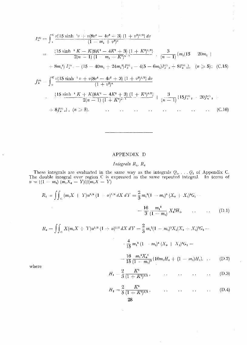
APPENDIX D
(C.16)
Integrals R 1 , R 2
These integrals are evaluated in the same way as the integrals Ql1 ... Q5 of Appendix C.The double integral over region C is expressed as the same repeated integral. In terms oftc = {(1 - m1) (m1XO- Y)}!(m1X + Y)
(D.l )
where
2 K5
H 2 = "5 (1 + K2)5/2 ,
28
(D.3)
(DA)

(D.S)
(D.6)
(D.7)
where K is given by (C.7) of Appendix C.
APPENDIX E
Integrals Sm,n
Again the double integral over region C is expressed as the repeated integral in Appendix Cand
is found to reduce to
where
5 =JJ (m X - y)m+l/2 (X -+ y)n+I/2 dX dYmen 1 0 I
C
4 J4> .5 = (m X -+- X )m+n+3 sln2m + 2 0 COS2n + 4 0 dom,n (2n + 3) I 0 I 0
4(1 + mI)n+3/2 X on+3/2 (Xl - X o)1n +3/2
(2m + 3) (2n + 3)
(E.1)
(E.2)
(E.3)
and the integral on the right-hand side of (E.2) may be evaluated by means of the reductionformulae
where
sin- ' ' (j cosm-
I 0 (m - 1)I = + I 2
n,m (n + m) n + m n,m-
sirr': ' () cosm+1 () (n - 1)
I = - -+ In,m . (n + m) n + m n-2,m
In,,,, = f sin" () cos" f..) d(). ..
29
}, .. (E.4)
(E.5)

APPENDIX F
These are evaluated by expressing the double integral over region A in Fig. 3 as a repeatedintegral:
ff fXO f1nlXA dX dY = 0 dX () dY.
Then it is easily found that
T = II (m 2X2 - Y 2)1/2dX dY =!!... m 2X 3.4 A 1 12 1 0,
30
(F.1)
(F.2)
(F.3)
(FA)
(F.5)

TABLE 1
Second Approximation to Derivatives for the Delta Wingof Aspect Ratio 1·8 and Taper Ratio 1/7
with Subsonic Leading Edges
M - Za. = - Zz - Za - ma = - m:i: -ma - ha = - h:i: - h'i-- --- -----~_._---
1 .1* ] '5(~6 ],774 1 ·676 2·305 0'(~880 1·2724
] ·1 1.5(~7 1·762 1·678 2·285 0'(~905 1 '2:~82
1 ·15 1·508 1·763 1·656 2·282 0·4208 1·2142
1·2 1 ·478 1·734 1·629 2·243 0·4358 1 ·1871
1·3 1·417 1·644 1·570 2·128 0·4469 1·1264
1'4 1·361 1·546 1·513 2·001 0·4482 1 ·OH55
1 ·5 1·309 1·453 1·457 1·882 0·4428 ioosn
1·6 1·260 1·367 1·405 1·771 0·4350 0·9487
1 '944t 1·116 1·125 1·249 1·460 0·4027 0'7923
* Indicates that the third approximations to the derivatives are given.
t Indicates the Mach number at which the wing has sonic leading edges.
The pitching axis is taken at the apex of the wing.
31

Mean chord. c = ~ (co + cf)Area of wing, 5 = 2s cControl surface ~AArea of control surface, Sf = 25 CAspecl: ratio of wing. 2s/c
Taper ralno of wing. cf/c o
z axis upwards
FIG. 1. Plan of wing and control surface. FIG. 3. 'Transform' of wing.
z
<>------hc
Free scream direction Ox
Angle of incidence R [ac e iwtJ
Complex upward displacement &
~ .Section of wing
FIG. 2. Motion of wing surface. FIG. 4. Areas of integration to obtain velocity potentials.

IS1·8\·71·6\·4 M 15HI1·2I I
FIG. 6. Variation of pitching-moment stiffness derivativewith Mach number.
---- r----.I----.---- h-= ~
-------r---r--t
----First approsrmabon
-- Second approximation
x Third approximal:ion
+ Ref 5_ (Mangler)
11.= I- -
+o1·0
10
0·9
O-B
0·6
o 5
0·4
0-7
01\
0-2
0·1
I-g1-81·71·61-4 M 1·5\-31·21·\
I I I I, - ---- First approximabon
5--- Second approximation
--......r-. x Third approximation+ Ref 5 (Mangler)
<,
<,
~" <,
~2
..............<;
I
0 , ,-
~"-9
<,<,
~-Za: ,-z<i
B <,~~
7 <,
<;<,6
<,
s
4
:I
-~-- ~<,
2~~
~I ............
-------o1·0
I
I-
I
l-
I-
0-
0-~~
0-
0-
0-
0-
0-
0-
0-
FIG. 5. Variation of lift derivatives with Mach number.

02
FIG. 7.
o10 I-I 1.1 1·2 1·3 1·4 M ,,5 10 '·7 1·8 rs
Variation of hinge-moment derivatives with Mach number.
I I I I Ix
~----- First approxirnacicn
---::-:--- Second approximation -
~ " Third approximation
x <, -h.er.
!'.. I'---..,,~r-, ~=~
I"--..........~
'"'~
-hci I--:.......<,~J
"-
-!La <,~
.~-
-
0·1
0·2
0·7
o-e;
0·4
1·0
0-8
0·9
,.
o1·0
FIG. 8.
'·9/·81·716/·3'·2 '.4M
/.&
Variation of pitching-moment damping derivativewith Mach number.
~ I I I I
~----- First approximation
~-..... -- Second approximation -
r-. x Third approximation
<,r-. IL=~
<,<.
<;
~)---.r---~r-- IL = I
I--r--I---
0·7
D·"
0·8
0·1
0·4
o·g
0·3
06

R. & M. No. 3060
Publication of theAeronautical i Research iCouncil
IS. 9d. (IS. lId.)2S. (2S. 2d.)2S. 6d. (2S. Iod.)2S. 6d. (2S. Iod.)2S. 6d. (2S. Iod.)
R. & M. No. 2350R. & M. No. 2450R. & M. No. 2550R. & M. No. 2650R. & M. No. 2750
R. & M. No. 2570 ISS. (I5s.8d.)
Reports of the Aeronautical Research
ANNUAL TECHN][CAL RElP'ORTS OF TH:~ AERONAUTlCAILRESEARCH COU~ClllL (BOUND VOLUMES)
1939 Vol. I. Aerodynamics General, Performance, AirscreJs, Engines. 50S. (52S.)Vol. II. Stability and Control, Flutter and Vibration, Instruments, Structures, Sea-
planes, etc. 63s. (65s.) i
1940 Aero and Hydrodynamics, Aerofoils, Airscrews, Engines; Flutter, Icing, Stability andControl Structures, and a miscellaneous section. 50S. (52s.)
1941 Aero and Hydrodynamics, Aerofoils, Airscrews, Engines, Flutter, Stability and Control Structures. 63s. (65s.)
1942 Vol. I. Aero and Hydrodynamics, Aerofoils, Airscrews, Engines. 75s. (77s.)Vol. II. Noise, Parachutes, Stability and Control, Structures, Vibration, Wind
Tunnels. 47s. 6d. (49s. 6d.)1943 Vol. I. Aerodynamics, Aerofoils, Airscrews. 80S. (82S.)
Vol. II. Engines, Flutter, Materials, Parachutes, Performance, Stability and Control, Structures. 90S. (92S. 9d.)
1944 Vol. I. Aero and Hydrodynamics, Aerofoils, Aircraft, Airscrews, Controls. 84s.(86s.6d.)
Vol. II. Flutter and Vibration, Materials, Miscellaneous, Navigation, Parachutes,Performance, Plates and Panels, Stability, Structures, Test Equipment,Wind Tunnels. 84s. (86s. 6d.)
1945 Vol. I. Aero and Hydrodynamics, Aerofoils. I30s. (I32S. 9d.)Vol. II. Aircraft, Airscrews, Controls. I30s. (1325. 9d.)Vol. III. Flutter and Vibration, Instruments, Miscellaneous, Parachutes, Plates and
Panels, Propulsion. I30s. (I32S. 6d.)Vol. IV. Stability, Structures, Wind Tunnels, Wind Tunnel Technique. 1305.
(I32S. 6d.)
Annual Reports of the Aeronautical Research Councll->-1937 2S. (2S. 2d.) 1938 IS. 6d. (IS. 8d.) 1939-48 3s. (3s. 5d.)
Index to all Reports and Memoranda published In the AnnualTechnical Reports, and separately-i-
April, 1950 R. & M. 2600 2S. 6d. (2S. Iod.)
Aullhor Index to ann Reports and Memoranda of the Aeronal'lLllticanResearch Ccuncll-«
I909--January, 1954
indexes to the TechnicalC01l.1l.DCil-
December I, 1936--June 30, 1939 R. & M. No. 1850 IS. 3d. (IS. 5d.)July I, 1939-June 30, 1945 R. & M. No. 1950 IS. (IS. 2d.)July I, 1945--June 30, 1946 R. & M. No. 2050 IS. (IS. 2d.)July I, I946--December 31, 1946 R. & M. No. 2150 IS. 3d. (IS. 5d.)January I, 1947--June 30, 1947 R. & M. No. 2250 IS. 3d. (IS. 5d.)
Published Reports and Memoranda of the Aeronautical ResearchCouncll->
Between Nos. 2251-2349Between Nos. 2351-2449Between Nos. 2451-2549Between Nos. 2551-2649Between Nos. 2651-2749
Prices in brackets include postage
HER MAJESTY'S STATIONERY OFFICEYork House. Kingsway, London W.C.2; 423 Oxford Street. London W.'I; I3a Castle Street, Edinburgh 2;39 King Street, Manchester 2; 2 Edmund Street, Birmingham 3; r09 St. Mary Street, Cardiff;
Tower Lane, Bristol. r; 80 Chichester Street, Belfast, Of through any bookseller.
S.O. Code No. 23·3060
R. & M. No. 3060