Embed Size (px)
Citation preview

Calibration of the wir epositionsof theATLAS Muon Chambersand studies
of Neutralino decaysat LHC
DissertationderFakultat fur Physik
der
Ludwig-Maximilians-UniversitatMunchen
vorgelegt von
SofiaChouridou
aus
Thessaloniki,Griechenland
Munchen,den22. Februar2002

1. Gutachter:Prof. Dr. D. Schaile2. Gutachter:Prof. Dr. M. Faessler
TagdermundlichenPrufung: 22. Mai 2002

Calibration of the wir epositionsof theATLAS Muon Chambersand studies
of Neutralino decaysat LHC
DissertationderFakultat fur Physik
der
Ludwig-Maximilians-UniversitatMunchen
vorgelegt von
SofiaChouridou
aus
Thessaloniki,Griechenland
Munchen,den22. Februar2002

���� �������� ������������ � �������������! #"%$'&($#)+*-,'$.�/�1032 .
Everythingis in anunceasingprocessof eternalflux.
Heraklitos(535-475BC).

To my mother, Mateniaandthememoryof my father, Themistoklis


Abstract
ATLAS is a general-purposedetectorthatis beingbuilt for theLargeHadronCollider(LHC) at CERN. The precisiontrackingdevicesof the ATLAS Muon Spectrometerarehigh pressureMonitoredDrift Tube(MDT) chambers.TheLHC physicsdiscov-ery potentialsetsstringentrequirementson theperformanceof thesechambers.Theyshouldbeableto achieve a momentumresolutionof 46587:9 for muonswith a trans-versemomentumof ;<>=?5 TeV. In orderto accomplishthis goal,theMDT chambersshouldbeconstructedwith 20 @ m mechanicalaccuracy (r.m.sof therelative distancebetweenthewiresof thedrift tubes).
Thepresentwork describesawire calibrationmethodfor theMDT chambers,with-out the useof any external referencesystem. The successof the methodin findingwire displacementsin thedirectionperpendicularto themuontrackswasverifieddur-ing two testbeamperiods: first the displacementsof 12 tubesweremeasuredwhilethechamberwasfilled with theold baselinegas A.BDC!EGFDC'HJI.K (91/4/5),andlaterwhilethenew baselinegaswasused( AGB�CLHNMOF (93/7)),wire displacementsof 52 tubeswerecalculated.The resultsof the methodwerecomparedwith thosegiven by the X-raytomographat CERN,revealinganaccuracy of themethodbetterthan10 @ m.
Simulationstudiesof theapplicationof themethodalongthefull width of acham-ber, were performedand were focussedon its systematicand statisticaleffects. Itturnedout that even when Gaussiandistributed time offsetsof 200 and 300 ps areaddedto thedrift time spectraof the tubes,the local uncertaintyremainsin theorderof 10 @ m. By combiningthelocal informationfor thewire displacementstheabsolutewire positionswithin thewholechamberwith respectto thefirst centralwireswithineachmultilayerareacquired.In this case,theglobalaccuracy of themethodis in theorderof 20 @ m. Moreover, consideringrandomanduncorrelatedwire displacementsthis accuracy improvesto 10 @ m.
This work alsopresentsstudiesrelevant to the ATLAS Supersymmetry(SUSY)discoverypotential.SUSYis consideredasaverymotivatedextensionof theStandardModelby many theorists.If it existsit will leadto discoveriesatLHC overmostof itsparameterspace.Within theMinimal Supergravity Model (mSUGRA)of SUSY, fiveparametersareusedin orderto determinethe massesandcouplingsof the particles.Six combinationsof theseparameters,selectedby the LHC Committeeandthe AT-LAS Collaborationfor detailedstudies,definerepresentative pointsof themSUGRAparameterspace.Thedecaychannel �PRQFNS �PRQ T�UWVRU%X througha virtual Z Y wasstudiedatthe fourth point of mSUGRA.Two versionsof PYTHIA werecomparedby studyingthedifferencesin theinvariantmassdistributionsof opposite-signsame-flavour leptonpairs. The newestversionof the two, includesthe spin-averagedmatrix elementinsparticledecays,thustakinginto accountthespinof theneutralinosandthepropaga-tor. The effect of this inclusionis profoundin mostof the caseswhile studyingthisspecificchannelin differentpointsof themSUGRAparameterspace.

Zusammenfassung
ATLAS ist ein Universalexperiment,dasfur den Large HadronCollider (LHC) am CERNgebautwird. Hochdruckdriftrohr(MDT) Kammernwerdenim ATLAS MyonspektrometerzurPrazisionsmessungvon Spurenwerwendet.DasEntdeckungsvermogendesLHC fur PhysiksetzthoheAnforderungenan die LeistungdieserKammern. Sie sollen fahig sein eine Im-pulsauflosungvon Z�[]\ fur Myonenzu erreichen,die einenTransversalimpulsvon ^ <`_ ZTeV haben. Um diesesZiel zu erreichen,sollten die MDT Kammernmit einer mechanis-chenGenauigkeit von 20 a m (die StandardabweichungdesrelativenAbstandeszwischendenDrahtenderDriftrohre)gebautwerden.
Die vorliegendeArbeit beschreibteineKalibrationsmethodefur dieMDT Kammern,ohneBenutzungeinesexternenReferenzsystems.Der Erfolg dieserMethodeim Auffinden derDrahtversetzungsenkrechtzuden MyonspurenwurdewahrendzweierTeststrahlperiodenuberpruft: zuerstwurdendie Versetzungenvon 12 Rohrengemessenwahrenddererdie Kam-mer mit demaltenbaselineGas bdc�egf F e]h�i K (91/4/5)und spatermit demneuen( bdc�ejhlk F(93/7)) aufgefullt war, die Drahtversetzungenvon 52 Rohrenwurdenberechnet.Die Ergeb-nissedieserMethodewurden mit denendes X-ray Tomographam CERN verglichen undzeigteneineGenauigkeit besserals10 a m.
Simulationsstudienfur dieAnwendungderMethodeentlangdervollenBreitederKammerwurdenausgefuhrt und konzentriertensich auf die systematischenund statistischenEffekte.Esstelltesichheraus,daßauchbeiGaußischverteiltenAbweichungendesDriftzeitnullpunktsvon 200und300ps,die lokaleUngenauigkeit in derGroßenordnungvon 10 a m bleibt. BeimVergleichder lokalenInformationfur die Drahtversetzungenwerdendie absolutenDrahtposi-tionenin derganzenKammerim VergleichzudenerstenzentralenDrahtenin jedemMultilayerbenotigt. In diesemFall ist dieglobaleGenauigkeit derMethodein derGroßenordnungvom20a m. Ferner, mit Rucksichtauf die zufalligenundunkorreliertenDrahtversetzungenverbessertsichdieGenauigkeit zu10 a m.
Die vorliegendeArbeit beinhaltetauchStudienzumATLAS Supersymmetrie(SUSY)Ent-deckungsvermogen. SUSY wird von vielen Theoretikern als gut motivierte ErweiterungdesStandardModels angesehen.Falls SUSY existiert wurde es bei LHC entdecktwerdenfurdengroßtenTeil desmoglichenParameterbereichs.Im Minimalen SupergravitationsModel(mSUGRA) von SUSY, werden5 Parameterbenutztum die Massenund KopplungenderTeilchenzuermitteln.SechsKombinationendieserParameterdefinierenreprasentativePunktedesmSUGRAParameterRaumes,die vom LHC Komiteeundder ATLAS KollaborationfurdetaillierteStudienausgewahltwurden.Der Zerfallskanal mn Q Flo mn Q Tqp V p X durchdenAustauscheinesvirtuellenZ Y BosonswurdeuntersuchtamPunktvier vonmSUGRA.Zwei VersionenvonPYTHIA wurdenverglichenindemdie Unterschiedein deninvarianteMasseverteilungenfurLeptonpaaremit entgegengesetztemVorzeichenundgleichemFlavouruntersuchtwurden.DieneuereFassungderbeidenVersionenerfasstdiespin-averagedMatrixelementein ZerfallenSu-persymmetrischerTeilchen,indemderSpindesNeutralinosunddesPropagatorsberucksichtigtwurde.In denmeistenFallen,in denendie spezifischenKanalein denverschiedenenPunktendesmSUGRAParameterRaumesuntersuchtwerden,ist ein klarerUnterschiedzwischendenbeidenVersionen.

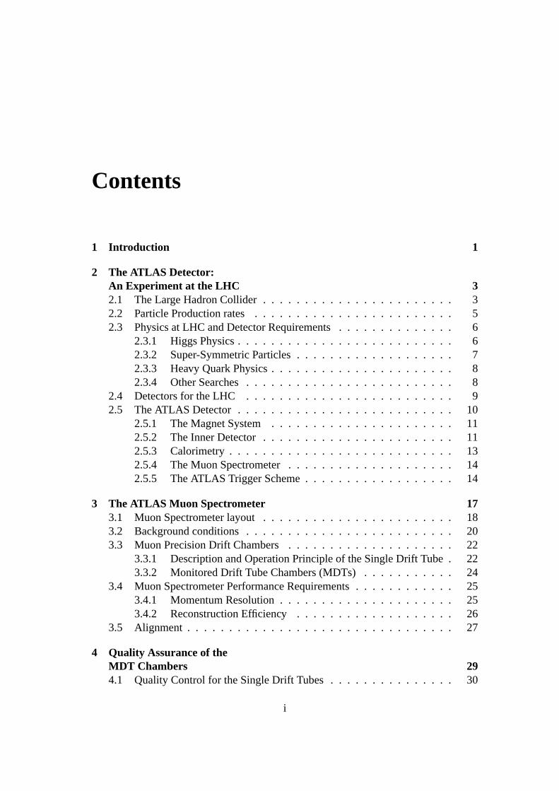
Contents
1 Intr oduction 1
2 The ATLAS Detector:An Experiment at the LHC 32.1 TheLargeHadronCollider . . . . . . . . . . . . . . . . . . . . . . . 32.2 ParticleProductionrates . . . . . . . . . . . . . . . . . . . . . . . . 52.3 Physicsat LHC andDetectorRequirements. . . . . . . . . . . . . . 6
2.3.1 HiggsPhysics. . . . . . . . . . . . . . . . . . . . . . . . . . 62.3.2 Super-SymmetricParticles . . . . . . . . . . . . . . . . . . . 72.3.3 Heavy QuarkPhysics . . . . . . . . . . . . . . . . . . . . . . 82.3.4 OtherSearches. . . . . . . . . . . . . . . . . . . . . . . . . 8
2.4 Detectorsfor theLHC . . . . . . . . . . . . . . . . . . . . . . . . . 92.5 TheATLAS Detector . . . . . . . . . . . . . . . . . . . . . . . . . . 10
2.5.1 TheMagnetSystem . . . . . . . . . . . . . . . . . . . . . . 112.5.2 TheInnerDetector . . . . . . . . . . . . . . . . . . . . . . . 112.5.3 Calorimetry . . . . . . . . . . . . . . . . . . . . . . . . . . . 132.5.4 TheMuonSpectrometer. . . . . . . . . . . . . . . . . . . . 142.5.5 TheATLAS TriggerScheme. . . . . . . . . . . . . . . . . . 14
3 The ATLAS Muon Spectrometer 173.1 MuonSpectrometerlayout . . . . . . . . . . . . . . . . . . . . . . . 183.2 Backgroundconditions . . . . . . . . . . . . . . . . . . . . . . . . . 203.3 MuonPrecisionDrift Chambers . . . . . . . . . . . . . . . . . . . . 22
3.3.1 DescriptionandOperationPrincipleof theSingleDrift Tube . 223.3.2 MonitoredDrift TubeChambers(MDTs) . . . . . . . . . . . 24
3.4 MuonSpectrometerPerformanceRequirements. . . . . . . . . . . . 253.4.1 MomentumResolution. . . . . . . . . . . . . . . . . . . . . 253.4.2 ReconstructionEfficiency . . . . . . . . . . . . . . . . . . . 26
3.5 Alignment . . . . . . . . . . . . . . . . . . . . . . . . . . . . . . . . 27
4 Quality Assuranceof theMDT Chambers 294.1 Quality Controlfor theSingleDrift Tubes . . . . . . . . . . . . . . . 30
i

ii CONTENTS
4.2 Qualityassuranceof theMDT chambers. . . . . . . . . . . . . . . . 33
5 Calibration of the wir e positionsof a BOS Chamber 375.1 Set-upfor the A.BDC!EGFDC'HJI.K Measurements. . . . . . . . . . . . . . . 37
5.1.1 Aligning theDrift TimeSpectra . . . . . . . . . . . . . . . . 395.1.2 TheLeast-SquaresTrackReconstructionTechnique. . . . . . 405.1.3 Descriptionof thewire calibrationmethod . . . . . . . . . . 425.1.4 ResultsandComparisonwith theX-ray Tomograph. . . . . . 45
5.2 Set-upfor the A.BDCLHrMOF Measurements. . . . . . . . . . . . . . . . . 485.2.1 TheGaschoice . . . . . . . . . . . . . . . . . . . . . . . . . 485.2.2 SpatialResolutionof thechamber . . . . . . . . . . . . . . . 505.2.3 ResultsandComparisonwith theX-ray Tomograph. . . . . . 51
5.3 Summary . . . . . . . . . . . . . . . . . . . . . . . . . . . . . . . . 54
6 Simulation studiesof the calibration method 556.1 Simulationfor individual flowerpairsof achamber . . . . . . . . . . 55
6.1.1 Systematicsdueto s Q . . . . . . . . . . . . . . . . . . . . . . 596.1.2 Statisticaleffects . . . . . . . . . . . . . . . . . . . . . . . . 61
6.2 Combininginformationfrom all flowerpairs. . . . . . . . . . . . . . 626.2.1 Statisticaleffects . . . . . . . . . . . . . . . . . . . . . . . . 65
6.3 Summary . . . . . . . . . . . . . . . . . . . . . . . . . . . . . . . . 65
7 Neutralino Decaysin ATLAS 677.1 Motivationfor extendingtheStandardModel . . . . . . . . . . . . . 677.2 Whatis SUSY? . . . . . . . . . . . . . . . . . . . . . . . . . . . . . 697.3 Minimal SupersymmetricStandardModel (MSSM) . . . . . . . . . . 71
7.3.1 SUSYbreaking. . . . . . . . . . . . . . . . . . . . . . . . . 737.3.2 Neutralinosandcharginos . . . . . . . . . . . . . . . . . . . 74
7.4 Minimal Supergravity Model (mSUGRA) . . . . . . . . . . . . . . . 757.4.1 mSUGRAparameterspacepointsat LHC . . . . . . . . . . . 76
7.5 NeutralinoDecayStudiesin mSUGRA . . . . . . . . . . . . . . . . 807.5.1 Main Characteristicsof thefourthpoint . . . . . . . . . . . . 807.5.2 Dileptoninvariantmassdistribution . . . . . . . . . . . . . . 827.5.3 Modifying theparametersof mSUGRA . . . . . . . . . . . . 87
7.6 Summary . . . . . . . . . . . . . . . . . . . . . . . . . . . . . . . . 97
8 Summary 99
Bibliography 103

Chapter 1
Intr oduction
For thousandsof yearstheunceasingandcurioushumanmind hasbeentrying to ex-plain theworld we live in anddefineits basicunderlyingreality. Thesimplequestion’what is theworld madeof?’ hasnotbeenfully answeredyet.
Thenotion thatmatteris madeup of small, indivisible particlesgoesbackto theancientGreeks.The greatphilosopherandscientistDemocritusof Abdera(460-370BC) developedtheatomichypothesisandcanbeconsideredasthefirst particlephysi-cist. Accordingto him, themattercanbesubdividedonly to a certainpoint at whichonly atoms,whosetiny sizecannot be diminished,remain. This hypothesisis stillvalid but of courseit hasbeenrevisedandprovenexperimentally. It wasthenin 1897whenThomsondiscoveredthe first tiny particles,the electrons,whenmodernparti-cle physicswasborn. Sincethosedaystheparticlephysicsdomainexperiencedmuchmorediscoveriesof new particlesandtheir interactions.The tremendoussuccessinsciencethe lastalmosthundredyearsresultedin the formationof aneffective theorythatdescribesour world; theStandardModel (SM).
Accordingto this theory the whole world is madeup of threegenerationsof el-ementaryparticles,eachcontainingtwo leptonsand two quarks,and twelve gaugebosonswhich mediatethe electromagnetic,weak and strong forces. The SM hasprovento beextraordinarilysuccessfulandits predictionshavebeentestedandverifiedto anunprecedentedprecision.Nevertheless,it cannotbeconsideredto betheultimatetheoryof Naturebecauseit cannotprovideanswersto many questions.Thereforeit isa work in progressandwill have to beextendedto describephysicsat arbitrarily highenergies.
ThesocalledGrandUnifiedTheories(GUT) setthemselvesthetaskto solveprob-lems that the SM can not solve. A very motivatedGUT theory is Supersymmetry(SUSY).It is apurelytheoreticalinventionthatgeneralizesthespace-timesymmetriesof quantumfield theoryby transformingfermionsinto bosonsandvice versa.Thatis,everyknown elementaryparticlehasasupersymmetricpartner, or superpartner, which
1
2 CHAPTER1. INTRODUCTION
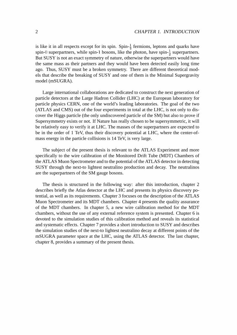
is like it in all respectsexceptfor its spin. Spin-TF fermions,leptonsandquarkshave
spin-7 superpartners,while spin-5 bosons,like thephoton,have spin-TF superpartners.
But SUSYis notanexactsymmetryof nature,otherwisethesuperpartnerswouldhavethe samemassastheir partnersandthey would have beendetectedeasily long timeago. Thus,SUSY mustbe a broken symmetry. Therearedifferenttheoreticalmod-els thatdescribethebreakingof SUSYandoneof themis theMinimal Supergravitymodel(mSUGRA).
Largeinternationalcollaborationsarededicatedto constructthenext generationofparticledetectorsat theLargeHadronCollider (LHC) at theEuropeanlaboratoryforparticlephysicsCERN,oneof the world’s leadinglaboratories.The goal of the two(ATLAS andCMS) out of thefour experimentsin total at theLHC, is not only to dis-cover theHiggsparticle(theonly undiscoveredparticleof theSM) but alsoto prove ifSupersymmetryexistsor not. If Naturehasreallychosento besupersymmetric,it willberelatively easyto verify it at LHC. Themassesof thesuperpartnersareexpectedtobe in the orderof 1 TeV, thustheir discovery potentialat LHC, wherethe center-of-massenergy in theparticlecollisionsis 14TeV, is very large.
The subjectof the presentthesisis relevant to the ATLAS Experimentandmorespecificallyto the wire calibrationof the MonitoredDrift Tube(MDT) ChambersoftheATLAS MuonSpectrometerandto thepotentialof theATLAS detectorin detectingSUSY throughthe next-to lightestneutralinoproductionanddecay. The neutralinosarethesuperpartnersof theSM gaugebosons.
The thesisis structuredin the following way: after this introduction,chapter2describesbriefly theAtlas detectorat theLHC andpresentsits physicsdiscovery po-tential,aswell asits requirements.Chapter3 focusesonthedescriptionof theATLASMuon Spectrometerandits MDT chambers.Chapter4 presentsthequality assuranceof the MDT chambers. In chapter5, a new wire calibrationmethodfor the MDTchambers,without theuseof any externalreferencesystemis presented.Chapter6 isdevotedto the simulationstudiesof this calibrationmethodandrevealsits statisticalandsystematiceffects.Chapter7 providesashortintroductionto SUSYanddescribesthesimulationstudiesof thenext-to lightestneutralinodecayat differentpointsof themSUGRAparameterspaceat theLHC, usingtheATLAS detector. The last chapter,chapter8, providesasummaryof thepresentthesis.

Chapter 2
The ATLAS Detector:An Experiment at the LHC
In theyear2006theoperationof theLargeHadronCollider(LHC), apowerful particleacceleratoris scheduledto start.
The LHC is the next stepin a voyageof discovery which began a centuryago.Backthen,scientistshadjust discoveredall kindsof mysteriousrays,X-rays,cathoderays,alphaandbetarays. Many questionshave beenansweredaboutthe origin andpropertiesof theseraysgiving usamuchgreaterunderstandingof theUniverse.At thedawn of the21stcentury, we facenew questionsin elementaryparticlephysicswhichLHC is designedto address.
In this chapterthe physics potentialof the collider as well as its impact on thedesignof theATLAS experimentarebriefly given.
2.1 The Lar geHadron Collider
TheLHC will bea proton-protoncollider with a center-of-massenergy t u of 2v 7 = 14 TeV. It will be installedin the existing 27 km of circumferencetunnelatCERNin Genevawhichhashousedtill Novemberof 2000theLargeElectronPositronCollider (LEP).Thedesignluminosityof LHC is 10w K cmX F sX T . Two bunchesof 10
TxTprotonseach,will collide every 25 ns. Theseprotonswill be preparedby CERN’sexistingacceleratorchain(seeFigure2.1)beforebeinginjectedinto thetwo LHC sep-aratebeamlinesthatwill hostthetwo protonbeams.
The high luminosity in combinationwith the very high center-of-massenergy oftheacceleratorwill allow theexplorationof particlephysicsup to energiesthatdom-inatedtheuniversejust 10X T F s after the ’Big Bang’ whenthe temperaturewasabout10T�y
K.
3

4 CHAPTER2. THE ATLAS DETECTOR: AN EXPERIMENTAT THE LHC
At theinteractionpoints(four in totalalongthetunnel)wherethetwo protonbeamsmeet,the transversebunchradiuswill be15 @ m andthebunchlengthwill be30 cm.Thismeansthatthepositionof thevertex will havearatherlargespreadalongthebeamdirection; theeffective spreadof thedistribution of thevertex positionis expectedtobe5.5cm (r.m.s)alongthebeamdirection.
*
*electronszpositrons{protons{antiprotons|Pb ions
LEP: Large Electron Positron colliderSPS: Super Proton Synchrotron}AAC: Antiproton Accumulator ComplexISOLDE: Isotope Separator OnLine DEvicePSB: Proton Synchrotron Booster~PS: Proton Synchrotron
LPI: Lep Pre-InjectorEP�
A: Electron Positron AccumulatorLIL: Lep Injector LinacLINAC: LINear ACceleratorLEAR: Low Ener�
gy Antiproton Ring
CERN �
Accelerators
OPALALEPH
L3DELPHI
SPS�
LEP
West Area�
TT
10
�AAC� T
T70
East Area
LPIe� -
e� -e� +EPA
PS
LEAR
LINAC
2
LIN
AC
3
p� Pb ions�
E2�
South Area�
Nor
th A
rea
LIL
TTL2TT2 E0
�PSB
ISO
LDE
E1
pbar
Rudolf LEY, PS Division, CERN, 02.09.96
FELIX
ATLAS
CMS
LEP LHC
ALICE LHC-B
Figure2.1: Schematicview of theCERNaccelerator complex.

2.2. PARTICLE PRODUCTIONRATES 5
2.2 Particle Production rates
In Figure2.2 thetotal proton-protoncross-sectiontogetherwith theproductioncross-sectionsfor somecharacteristicprocessesasa functionof thep-p centre-of-massen-ergy areshown. Thetotalcrosssectionis estimatedto bebetween90and130mb. Thiswill result in about20 interactionsper bunchcrossing(i.e every 25 ns) at the designluminosityof 10w K cmX F sX T . At this luminositythecollisionratewill be10� collisionspersecondandthetotal integratedluminosityis expectedto be10� pbX T peryear.
σ tot
σ� jet�
σ�
σ� t t�
E >0.03 s
(W )ν�
σ� z'�σ� Higgs
m = 500 GeVH
m = 200 GeVtop
m = 1 TeV
1 mb
1 b
1 nb
1 pb
µ�
0.1 1.0 10 100
s TeV�
T
jet �
z'
σ
σ� jet�
E >0.25 TeVT
jet �
σb b
(pro
ton
- pr
oton
)
0.001 0.01
CERNFermilab
LHCSSC
UA1
E710
UA4/5
UA1/2
CDF (p p)
(p p)
9�
7�
5�
-1
3�
Eve
nts
/ sec
for
=
10
cm
s
ec
34-2
-1
10
10
10
10
10
-310
10
D.D
354
c CDF
CDFm = 174 GeVtop
Figure2.2: Thecross-sectionof somecharacteristicprocessesat LHC asa functionofthep-p centre-of-massenergy [DEN90].

6 CHAPTER2. THE ATLAS DETECTOR: AN EXPERIMENTAT THE LHC
2.3 Physicsat LHC and DetectorRequirements
Oneof themaingoalsof LHC is to studytheactualmechanismof symmetrybreakingin the electroweaksector( ��� "%�L2 v � " 5 2 ) of the StandardModel (SM). This mech-anismis associatedwith the Higgs Boson. Thereforethe Higgs searchis usedasabenchmarkfor detectoroptimization.
The high energy and luminosity of the LHC offers a large rangeof physicsop-portunities,from the precisemeasurementsof the propertiesof known objectsto theexplorationof the high energy frontier. Thereforebesidesthe Higgs search,severalotherprocesseswill be usedasbenchmarksfor the detectordesign.All theseexam-ples of physics at LHC as well as the stringentdetectorrequirementsthey set, arediscussedin this sectionbriefly.
2.3.1 HiggsPhysics
Thelastunobservedparticlefrom theStandardModelis theHiggsboson.Its discoverywould allow oneto completethe SM paradigmandconfirmthe mechanismof spon-taneoussymmetrybreaking.On the contrary, the absenceof the Higgs bosonwouldawakedoubtsaboutthewholepictureandwould requirenew concepts.Thereforeoneof themaintopicsin LHC studieswill bethesearchfor theSM Higgsboson.
Thetotal Higgsproductioncrosssectionat LHC is predictedto rangebetween0.1pb and100pb dependingon theHiggsmass.Thedominantproductionmechanismsare gluon-gluonfusion, WW fusion andZZ fusion while lessimportantproductionprocessesare tt fusion and Higgs bremsstrahlungfrom W or Z. Only a few decaychannelsof the Higgs bosonareaccessibleto experimentalobservation at LHC be-causeeitherthedecaychannelshavesmallbranchingratiosor thedecaysareobscuredby alargebackgroundof eventsthatcarrythesignatureof theHiggs.Hencethediffer-entHiggsdecaychannels,describedbelow, for theHiggsmassrangingfrom 80 GeVto 1 TeV arethemostprominentbenchmarkprocessesfor thedetectorsdesignatLHC.
The currentHiggs masslower limit is set to 114.1GeV. It hasbeenderived bydirect searchesat LEP, which hadto stop in November2000asthe acceleratorwasswitchedoff giving its placeto theLHC [LEP01].
Figure2.3 shows the branchingratiosof Higgsdecaychannelsdependingon theHiggsmass:
� 80GeV �¡ £¢¤� 120GeV:Below the WW or ZZ thresholdthe largestHiggs decaybranchingratio willbe H S bb. Sincethis decaychannelis obscuredby QCD background,thereconstructionandtaggingof b-jetswith high efficiency is a crucialelementin

2.3. PHYSICSAT LHC AND DETECTORREQUIREMENTS 7
thedetectorperformance.Another promising channel in this massrangeisH S ¥�¥ althoughit suffersfrom very largebackground.For suchdetectionsanelectromagneticcalorimeterwith high resolutionandexcellent photon/jetandphoton/electrondiscriminationis required.
� 120GeV �¡ >¢¦� 180GeV:In this massregion the decayH S Z § Y S 4UW¨ (where U = e, @ ) provides averycleansignature.Verygoodleptonenergy/momentumresolutionis required(about19 ).
� 180GeV �¡ >¢¦� 800GeV:ThedecayH S ZZ S 4U is consideredto bethemostreliablediscoverychannelsincetheexpectedsignalratesarelargeandthebackgroundsmall.
� £¢¤©«ªL7L7 GeV:For this heavy Higgs bosonthe decayH S ZZ S UWV¬U�X��� is relevant andit issix timesmorefrequentthantheH S ZZ S 4U . This signatureis characterizedby thehigh missingtransverseenergy dueto theescapingneutrinosandby twochargedhigh ;< leptons. Anotherpromisingchannelin this massrangeis HS ® V ® X S U¯�'°]° (° denotesa jet).
±�²�² ³�²�² ´�²�² µ�²�² ¶�²·² ¸·²�²
±¹²�º
±¹² −»
±¹² − ¼±¹² −½
±¹² −¾±¹² −¿
γÀ γÀÁ1ÂÃÄÅÆÇ ÄÈÉ ÃÊÇ1Ë
ÌÍÏÎ�Î�Ð:ÑlÒ�Ð�ÐrÓÕÔ�ÖØ×Ù
τÚ +τÚ −
ÛÜÛ ÝÞÝ
ßà�à
ßá]á
â%â ß
Figure2.3: Branching ratiosof theHiggs.
2.3.2 Super-Symmetric Particles
In the Minimal Supersymmetricextensionof the SM (MSSM) thereis a family ofHiggs bosons:a chargedbosonpair(I ¨ ) andthreeneutralbosons(h, I Q , A). More

8 CHAPTER2. THE ATLAS DETECTOR: AN EXPERIMENTAT THE LHC
aboutthis extensionof the SM can be found in chapter7. For the searchof thesebosonsefficient secondaryvertex detectionfor leptonsandb quarksaswell ashighresolutioncalorimetryfor jetsandmissingtransverseenergy areessential.Thesearchof thelightestsupersymmetricparticle(LSP),which is stable(assumingR-paritycon-servation) andescapesdetection,setsstringentrequirementsfor the hermeticityandmissingtransverseenergy of thedetectors.
2.3.3 Heavy Quark Physics
An importantchapterof LHC physicswill be thestudyof heavy quarksystems.Al-readyat initial lower luminosity the LHC will be a high ratebeautyand top quarkfactory. LHC hasa greatpotentialfor performinghigh precisiontop physics mea-surementswith abouteightmillion tt pairsexpectedto beproducedfor an integratedluminosityof 10 fb X T . It would allow not only for theprecisemeasurementof thetopquarkmass(with precisionof 4 2 GeV) but alsothedetailedstudyof its properties.Themainemphasisin B physicsstudieswill begiven to theprecisemeasurementofCP-violationin the ã Qä systemand the determinationof the anglesin the Cabibbo-Kobayashi-Maskawaunitarity triangle.In addition,investigationsof BB mixing in theã Qå system,rareB decaysandgeneralspectroscopy of stateswith b quarkswill beofgreatinterest.
Precisesecondaryvertex determination,full reconstructionof final stateswith rel-atively low-;< particlesand low-;�< leptonfirst level trigger aswell assecondleveltracktriggeringcapabilityarenecessaryrequirementsfor theLHC experiments.
2.3.4 Other Searches
MaybeNaturehasnotchosentheHiggsmechanismasthemechanismresponsiblefortheelectroweaksymmetrybreaking.ThereforeatLHC searchesfor signaturesof tech-nicolor models,which could replacethe Higgs bosonsof the SM or MSSM, will beperformed.
Therearealsootherpossibilitiesfor new physicsthatarenotnecessarilyrelatedtothescaleof electroweaksymmetrybreaking.Therecouldbefor examplenew neutralor chargedgaugebosonswith masseslargerthanthoseof theZ andW bosons.Severalextensionsof theStandardModel postulatetheexistenceof suchheavy gaugebosons(Z’ andW’). They couldbeaccessibleat LHC for massesup to 5-6 TeV. Consideringtheir leptonicdecays,high resolutionleptonmeasurementsandcharge identificationareneededevenin a ;�< rangeup to a few TeV.
The LHC experimentsfinally will alsobe able to performnew physicssearchesfor leptoquarks,quarkand leptoncompositeness,magneticmonopolesandmassiveneutrinos.
2.4. DETECTORSFORTHE LHC 9
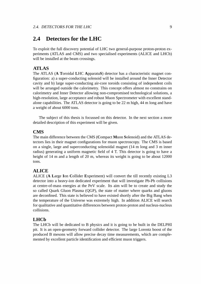
2.4 Detectorsfor the LHC
To exploit thefull discovery potentialof LHC two general-purposeproton-protonex-periments(ATLAS andCMS) andtwo specialisedexperiments(ALICE andLHCb)will beinstalledat thebeamcrossings.
ATLASThe ATLAS (A Toroidal LHC ApparatuS) detectorhasa characteristicmagnetcon-figuration: a) a super-conductingsolenoidwill be installedaroundtheInnerDetectorcavity andb) large super-conductingair-coretoroidsconsistingof independentcoilswill bearrangedoutsidethecalorimetry. This conceptoffersalmostno constrainsoncalorimetryandInnerDetectorallowing non-compromisedtechnologicalsolutions,ahigh-resolution,largeacceptanceandrobustMuonSpectrometerwith excellentstand-alonecapabilities.TheATLAS detectoris goingto be22 m high,44 m long andhaveaweightof about6000tons.
The subjectof this thesisis focussedon this detector. In the next sectiona moredetaileddescriptionof this experimentwill begiven.
CMSThemaindifferencebetweentheCMS(CompactMuonSolenoid)andtheATLAS de-tectorslies in their magnetconfigurationsfor muonspectroscopy. TheCMS is basedon a single, large andsuperconductingsolenoidalmagnet(14 m long and3 m innerradius)generatinga uniform magneticfield of 4 T. This detectoris going to have aheightof 14 m anda lengthof 20 m, whereasits weight is going to be about12000tons.
ALICEALICE (A Large Ion Collider Experiment)will convert the till recentlyexisting L3detectorinto a heavy-ion dedicatedexperimentthat will investigatePb-Pbcollisionsat centre-of-massenergiesat the PeV scale. Its aim will be to createandstudy theso calledQuarkGluon Plasma(QGP), the stateof matterwherequarksandgluonsaredeconfined.This stateis believedto have existedshortlyafter theBig Bangwhenthe temperatureof the Universewasextremelyhigh. In additionALICE will searchfor qualitativeandquantitativedifferencesbetweenproton-protonandnucleus-nucleuscollisions.
LHCbThe LHCb will be dedicatedto B physicsandit is going to be built in the DELPHIpit. It is anopen-geometryforward collider detector. The large Lorentzboostof theproducedB mesonswill allow precisedecaytime measurements,which arecomple-mentedby excellentparticleidentificationandefficient muontriggers.

10 CHAPTER2. THE ATLAS DETECTOR: AN EXPERIMENTAT THE LHC
For moredetailedinformationaboutthe four detectorsmentionedabove, seetherespective technicalproposalsof the experiments;[ATL94], [CMS94], [ALI95] and[LHCb98].
2.5 The ATLAS Detector
TheATLAS Collaborationproposesto built a general-purposeproton-protondetectorwhichis designedto exploit thefull discoverypotentialof theLHC. TheCollaborationsubmitteda Letter of Intent in 1992, a TechnicalProposalin 1994 and since thenseveral TechnicalDesignReports(TDRs) for eachsubsystemincluding mostof thefinal specificationshave beenpublished.The constructionphasehasalreadystartedfor mostof thedetectorcomponentsandtheexperimentis scheduledto be readyforthestartof LHC in summer2006.Theoverall layoutof theATLAS detectoris shownin Figure2.4.
Figure2.4: Overall Layoutof theATLASdetector.

2.5. THE ATLAS DETECTOR 11
The observablecross-sectionsfor most of the processesare small over a large partof massrange.Thereforean importantdesignconsiderationis to operatein high lu-minosityandto maximisethedetectableratesabove backgroundsby high-resolutionmeasurements.
Thebasicdesignconsiderationsarethefollowing:
� Very good electromagneticcalorimetry for electronand photon identificationandmeasurements,complementedby full-coveragehadroniccalorimetryfor ac-curatejet andmissingtransverseenergy ( æèçêéìë�ë< ) measurements.
� High-precisionmuonmomentummeasurements,with thecapabilityto guaran-tee accuratemeasurementsat the highestluminosity using the external muonspectrometeralone.
� Efficient tracking at high luminosity for high-;�< lepton-momentummeasure-ments,electronandphotonidentification, -leptonandheavy-flavour identifica-tion andfull eventreconstructioncapabilityat lower luminosity.
� Large acceptancein pseudorapidity( í ) with almost full azimuthalangle ( î )coverageeverywhere.Theazimuthalangleis measuredaroundthe beam-axis,whereaspseudorapidityrelatesto the polar angle ( ï ) with íð= )Gñóòõô·ö'ò¬" ï(C �(2where ï is theanglefrom thez-direction(alongthebeamline).
� Triggeringandmeasurementsof particlesat low-;�< thresholds,providing highefficienciesfor mostphysicsprocessesof interestatLHC.
2.5.1 The Magnet System
The ATLAS superconductingmagnetsystem[ATLm97] is an arrangementof a cen-tral thin solenoid(CS) [ATLc97] providing the Inner Detectorwith magneticfield,surroundedby a systemof threelargeair-coretoroidsconsistingof independentcoilsarrangedwith an eight-fold symmetrythat generatethe magneticfield for the muonspectrometer. Theoverall dimensionsof themagnetsystemare26m in diameter. Thetwo end-captoroids(ECT) [ATLe97] areinsertedin thebarreltoroid (BT) [ATLb97]at eachendandline up with theCS.TheCSprovidesa centralfield of 2 T while thethreeair-coretoroidsprovide an averagetoroidal field of 0.5 T in the muonsystem.The magnetsare indirectly cooledby forcedflow of helium at 4.5 K throughtubesweldedon thecasingof thewindings.
2.5.2 The Inner Detector
The InnerDetector[ATLi97a] (seeFigure2.5) combineshigh-resolutiondetectorsattheinnerradii with continuoustrackingelementsat theouterradii, all containedin theCentralSolenoid. The momentumandvertex resolutionrequirementsfrom physics

12 CHAPTER2. THE ATLAS DETECTOR: AN EXPERIMENTAT THE LHC
call for high-precisionmeasurementsto bemadewith fine-granularitydetectors,giventheenormoustrackdensityexpectedat theLHC.
Forward SCT
Barrel SCT
TRT
Pixel Detectors
Figure2.5: Three-dimensionalcutawayview of theATLASInner Detectorconsistingof the Pixel Vertex Detector, the SemiConductorTracker (SCT)and the TransitionRadiationTracker (TRT).
ThereforetheInnerDetectorconsistsof threeparts:
÷ ThePixel VertexDetector [ATLp98] whichwill provideaveryhigh-granularityandhigh-precisionsetof measurementsvery closeto theinteractionpoint. The140 millions of pixels form threebarrelsat averageradii of 4, 10 and13 cmandfive diskson eachsideof the systembetweenradii of 11 and20 cm. Thepixelsshouldnotonly havetiny dimensions(50 ø m ù 300 ø m) in orderto fulfilltherequiredtaskof patternrecognitionin thecrowdedenvironmentof theLHCbut also shouldbe radiationhardenedto withstandover 300 kGy of ionisingradiationandover 5 ù 10ú¹û neutronspercmü over tenyearsof operation.Thespatial resolutionin the azimuthaldirection Rý (the bendingdirection of thesolenoid)will be12 ø m while alongthez direction(thedirectionof thebeam)will be70 ø m.
÷ The SemiConductor Tracker (SCT) [ATLi97b] which will consistof siliconmicrostripdetectorsforming four completebarrelsat radial distancesbetween30 and52 cm. Eachsilicon detectorwill be6.36 ù 6.40cmü with 768readout

2.5. THE ATLAS DETECTOR 13
stripsof 80 ø m pitch. The SCT systemis designedto provide four precisionmeasurementspertrackin theintermediateradialrangecontributing to themea-surementof momentum,impactparameterandvertex position. The resolutionwill be16 ø m in Rý and580 ø m in z direction.
÷ The Transition Radiation Tracker (TRT) [ATLi97b] which will consistofstraw detectorsof 4 mm in diameterandequippedwith a 30 ø m diametergold-platedW-Rewire. Thestraws will befilled with a þGÿ������ û ����� ü gasmixture.Thebarrelregion will containabout50000straws in axial orientationwhile theend-capwheelswill contain320000in radial orientation. Eachstraw channelprovidesadrift-time measurement(giving aresolutionof 170 ø m perstraw) andtwo independentthresholds. In this way the discriminationbetweentrackinghits, which passthe lower threshold,and transition-radiationhits, which passalsothehigheronewill bepossible.
2.5.3 Calorimetry
The ATLAS calorimetrysystem[ATLcl96] is shown in Figure2.6. It consistsof anelectromagnetic(EM) calorimetercovering the pseudorapidityregion � ��� 3.2, ahadronicbarrel calorimetercovering � ��� 1.7, hadronicend-capcalorimeterscov-ering1.5 ��� ��� 3.2andforwardcalorimeterscovering3.1 ��� ��� 4.9.
The ElectromagneticCalorimeter (EM)
The EM Calorimeter[ATLl96] is a lead/liquid-argon (LAr) detectorwith accordion-shapedKaptonelectrodesand leadabsorberplatesover its full coverage. The totalthicknessof the EM calorimeteris larger than24 radiationlengths( þ�� ) in thebarrelandlarger than26 þ�� in theend-caps.A granularityof �� ù�� ý�� 0.025 ù 0.025isaimingfor anenergy resolutionof ��������� 10� � ��!#"#ÿ%$'& andanangularresolutionof 50mrad� ��!("#ÿ%$)& .The Hadronic Calorimeter
Thebarrelhadroniccalorimeter[ATLl96, ATLt96] is asamplingcalorimeterusingironasanabsorberandscintillatingtilesastheactivematerial.It coversthepseudorapidityregion � ��� 1.7andextendsradially from aninnerradiusof 2.28m to anouterradiusof 4.25m. Over the range1.5 �*� �+� 4.9, LAr calorimetersareused:thehadronicend-capcalorimeterextendsto � ��� 3.2andis acopper-LAr detectorandtheforwardcalorimetersthatcoversthe region 3.2 �,� �+� 4.9 andarebasedon rodsfilled withLAr in acopperandtungstenmatrix. Theenergy resolutionof thehadroniccalorimeterwill be �������-� 50� � ��!#"#ÿ%$'& for � �.� 3 and ��������� 100� � ��!#"#ÿ%$'& for 3 �� ��� 4.9.

14 CHAPTER2. THE ATLAS DETECTOR: AN EXPERIMENTAT THE LHC
Hadronic TileCalorimeters
EM AccordionCalorimeters
Hadronic LAr End CapCalorimeters
Forward LArCalorimeters
ATLAS Calorimetry
Figure2.6: Three-dimensionallayoutof theATLAScalorimetrysystem.
2.5.4 The Muon Spectrometer
The ATLAS Muon Spectrometer, the outer layer of the ATLAS detectorwill be de-scribedin moredetail in thenext chapter.
2.5.5 The ATLAS Trigger Scheme
The taskof the trigger systemis to identify bunchcrossingsthat containinterestingphysicsevents.Startingfrom aninitial bunch-crossingrateof 40MHz (correspondingto 10/ collisions/s),therateof selectedeventswill bereducedto 0 100Hz for perma-nentstorage.Thetriggerschemeis basedon threelevelsof onlineeventselection:
÷ The Level-1 trigger (LVL1) makes the initial selectionof interestingbunch-crossingsusingreduced-granularityinformationfrom asubsetof detectors.TheLVL1 latency (time taken to form anddistribute the LVL1 decision)will be 2ø s. After theLVL1 theeventratewill bereducedto 75 kHz (upgradableto 100kHz).

2.5. THE ATLAS DETECTOR 15
÷ The Level-2 trigger (LVL2) is designedto reducetheLVL1 triggerrateto 0 1kHz by usingfull-granularityandfull-precisiondatafrom mostof thedetectors.LVL2 processingis restrictedto ’Regionsof Interest’(RoI)providedby theLVL1trigger. Its latency is variablefrom eventto eventandit is expectedto bein therange1-10ms.
÷ The Level-3trigger (LVL3) performsthelaststageof theonlineselectionusingthe full event data. Eventsthat satisfy the final criteria arestoredfor off-lineanalysis.Theoutputeventrateis finally reducedto 0 100Hz.


Chapter 3
The ATLAS Muon Spectrometer
High-momentumfinal-statemuonsareamongstthe most promisingand robust sig-naturesof physicsat theLHC. To exploit this potential,theATLAS Collaborationhasdesignedahigh-resolutionmuonspectrometer(Figure3.1)with stand-alonetriggeringandmomentummeasurementcapabilityover a wide rangeof transversemomentum,pseudorapidityandazimuthalangle.
Thelayoutof thespectrometeris basedon themagneticdeflectionof muontracksin a systemof threelarge superconductingair-core toroid magnets(Figure 3.2) (inorderto avoid resolutiondeteriorationby multiplescatteringin amassivecore)instru-mentedwith separate-functiontriggerandhigh-precisiontrackingchambers.
End-captoroid1
Barrel toroidcoils2
Calorimeters
MDT chambersResistive plate chambers
Inner detector
Figure3.1: Transverseview of theATLASMuonSpectrometer.
17

18 CHAPTER3. THE ATLAS MUON SPECTROMETER
Figure 3.2: Three-dimensionalview of the superconductingair-core toroid magnetsystem(consistingof a barrel and two end-caps).Theright-handend-capmagnetisshownretractedfromits operatingposition.
In thepseudorapidityrange � �43 1.0,magneticbendingis providedby a largebarrelmagnetconstructedfrom eight coils surroundingthe hadroncalorimeter. For 1.4 3� ��3 2.7,muontracksarebentin two smallerend-capmagnetsinsertedinto bothendsof the barrel toroid. In the interval 1.0 35� �63 1.4 referredto astransitionregion,magneticdeflectionis providedby a combinationof barrelandend-capfields.
3.1 Muon Spectrometer layout
The layout of the muonchambersin the ATLAS detectorcanbe seenin Figure3.3wherethedifferentregionscoveredby four differentchambertechnologiesareshown.Thechambersarearrangedsuchthatparticlesfrom theinteractionpoint traversethreestationsof chambers.
More specificallyin the barrel region the chambersform threecylindrical layers(‘stations’)concentricwith thebeamaxis.In thisregiontheparticlesaremeasuredneartheinnerandouterfield boundariesandinsidethefield volume,in orderto determinethemomentumfrom thesagittaof thetrajectory. Theend-capchambersarearranged

3.1. MUON SPECTROMETERLAYOUT 19
in four disksconcentricwith the beamaxis. Over mostof the pseudorapidityrange,a precisionmeasurementof the track coordinatesin the principal bendingdirectionof the magneticfield is performedby Monitored Drift Tube (MDT) chambers(seeSection3.3.2). At large pseudorapiditiesandcloseto the interactionpoint wheretheparticlefluxesarevery high, insteadof MDTs, CathodeStrip Chambers(CSCs)areemployed.
chamberschambers7
chambers
chambers
Cathode strip8
Resistive plate
Thin gap
Monitored drift tube
Figure3.3: Three-dimensionalview of themuonspectrometerinstrumentationindicat-ing theareascoveredby thefour differentchambertechnologies.
Thetriggersystemcoversthepseudorapidityrange� ��3 2.4. In thebarrelthetrig-ger function is providedby threestationsof Resistive PlateChambers(RPCs).Theyarelocatedon both sidesof the middle MDT stationandeitherdirectly above or di-rectly below theouterMDT station.In theend-caps,thetriggeris performedby threestationsof Thin GapChambers(TGCs)locatednearthemiddleMDT station.Both oftheRPCsandTGCsalsoprovide the’secondcoordinate’measurementof trackcoor-dinatesorthogonalto theprecisionmeasurement,in adirectionapproximatelyparallelto themagneticfield lines.

20 CHAPTER3. THE ATLAS MUON SPECTROMETER
3.2 Background conditions
While theparticlesin theInnerDetectorcomemainly from theprimaryproton-protoninteraction,theparticleflux in themuonspectrometeris theresultfrom achainof com-plex interactionsin the calorimetryandshieldingand is thereforeaffectedby muchlargeruncertainties.
Thehigh level of particlefluxesin thespectrometerplaysanimportantrole for thedesignof its instrumentationanddefinesthe specificationsfor ratecapability, gran-ularity, ageingpropertiesandfinally radiationhardness.Trigger andreconstructionalgorithmsalsomustbe carefully optimizedto dealwith the demandingbackgroundconditions.
c 9 → µ b → µ t :
→ µ W ;
→ µ Z/<
γ* → µ π= /K → µ Shower muons Punch-through |ηµ| < 2.7
10–6
10–5
10–4
10–3
10–2
10–1
1
10
dσ/d
p T (
µbar
n/G
eV)
pT (GeV)µ>0 10 20?
30@
40A
50 0 0.5 1 1.5 2 2.5
ηB10–6
10–5
10–4
10–3
10–2
10–1
1
10
dσ/d
η (µ
barn
/0.1
) c C → µ b → µ t D
→ µ W E
→ µ Z/F
γ* → µ πG /K → µ
pT > 3 GeV
Figure3.4: Expectedinclusivecross-sectionfor primary collision products[CHE93]:(a) asa functionof thetransversemomentumHJI , integratedover � �K� 2.7and(b) asa functionof therapidity, integratedover3 �LHJI�� 50GeV.
Therearetwo categoriesof backgroundsources:
1. Primary collision products that arecorrelatedin time to the primary p-p col-lision andthey penetrateinto the muonspectrometerthroughthe calorimeters.Sourcesof thiskind of backgroundaremuonsproducedin thedecaysof:
÷ heavy-flavour hadrons( M�NPONPQ�R øþ );÷ gaugebosons(W, Z, SUT6R øþ );÷ light hadronsin flight ( VWR øþ ) in theinnertracker cavity;÷ hadronicdebrisproducedin thecalorimetershowers(showermuons),

3.2. BACKGROUND CONDITIONS 21
andfinally asmallfractionof hadronsinteractinglateornotatall in thecalorime-tersandthereforepenetrateinto themuonspectrometer(hadronpunch-through)(Figure3.4a).
Muonswith momentumlessthanabout3 GeV will not reachthe muoncham-bers.For transversemomentaHJI�X 10 GeV theinclusive muoncross-sectionisdominatedby charmandbeautydecays.At larger HJI-X 30 GeV, top andZ de-caysalsogive a sizeablecontribution. If we comparethoughtheprompt-muon(i.e. correlatedin time to the primary p-p collision) andhadroniccomponentsthatreachthemuonchambers,wereachtheconclusionthatthecalorimetersys-tem hasenoughabsorptive power to suppresshadronicdebriswell below theirreduciblelevel of thepromptmuons.Thetotalcountingratefrom primarycol-lision productsis dominatedby low-HYI pionandkaondecaysin theinnertrackercavity (Figure3.4b)
2. Radiation background, whichconsistsmostlyof low-energy (1 MeV) neutronsandphotonsandis producedby secondaryinteractionsin theforwardcalorime-ter, shieldingmaterial,thebeampipeandmachineelements(Figure3.5a).Thiskind of backgrounddueto frequentrescatteringis not any longercorrelatedintime to the primary p-p interaction. Although the photonand neutronsensi-tivities of the MDTs areonly 0.45� and0.1� respectively [BAR94, CHL93],countingratesup to 100Hz/cmü areexpected(Figure3.5b).
2.3 < η < 2.7
1.4 < η < 2.3
0 < η < 1.4
(a)
1
10–1
10–2
10–3
0 1 2 3
ηZ
Cou
ntin
g ra
te (
kHz/
cm2 )
Middle station
Outer station
Inner station
Figure3.5: (a) Theexpectedphotonflux as a functionof photonenergy in differentpseudorapidity regionsof thespectrometer, (b) pseudorapiditydependenceof thetotalcountingratein thethreeprecisionchamberstations.

22 CHAPTER3. THE ATLAS MUON SPECTROMETER
The ATLAS collaborationdecidedto designthe muonsystemfor a five timeshigherbackgroundthanexpectedasthebackgroundrateshaveanuncertaintyofa factorfive dueto the superpositionof differentcontributions: First therearetheuncertaintiesof the total p-p cross-sectionandof themultiplicity producedin theprimarycollisions(factor1.3). Furthermorethechambersensitivities areuncertainby a factorup to 1.5. And lastly the limited knowledgeof theshow-eringprocessesin theabsorberandof the ( [N\S ) cross-sectionsandtheensuingneutronandphotonproductionhasbeenassumedto contributeby a factor2.5.However, recentwork [GSC00] hasshown that this uncertaintyresultingfromtheshowerprocessescanbereducedto a factor1.2.
The effects of the high-rateradiationbackgroundon drift chamberoperationwerestudiedata test-beamexperimentwith a stronggammasource[DEI00].
3.3 Muon PrecisionDrift Chambers
Over mostof the pseudorapidityrangeof the muonspectrometerthe technologyofthe MonitoredDrift TubeChambers(MDT) is usedasprecisionchambers(seealso[HES98]). Themuonmomentain thespectrometerwill bereconstructedfrom a mea-surementof thesagittain threemuonprecision-chamberstations.To achieve the re-quiredmomentumresolutionat high momenta(thesagittafor a 1 TeV muonis about500 ø m) themuoninstrumentationhasto provideapositionmeasurementaccuracy ofabout50 ø m perstation.
In this sectionwe describein somedetail this kind of chambersstartingwith theirconstituents.
3.3.1 Description and Operation Principle of the SingleDrift Tube
The basicdetectionelementsof the MDT chambersarecylindrical aluminiumdrifttubeswith adiameterof 3 cmand400 ø m wall thicknesshaving acentralW-Resensewire of 50 ø m diameterthat is connectedto positive high voltage. The tubesareoperatedwith non-flammablegasmixtureat 3 barabsolutepressureandareclosedatbothendsby end-plugs.Theseend-plugsprovide thefixation of thecentralwire andits electricalcontact.They alsocontainthegassealsfor eachtubeaswell asthegasconnectorsto thegasmanifold.Thetubelengthsvary from 1 to 6 m.
Theprincipleof operationis shown in Figure3.6. Whena muontraversesa drifttube, it interactselectromagneticallycausingionizationof the detectorgasandpro-ducingclustersof electronsalongits track.Sincethecollisionswith thegasatomsarerandom,thenumberof ionizationclustersperunit of tracklengthis Poissondistributed
3.3. MUON PRECISIONDRIFT CHAMBERS 23
tt
]]^^_ _ _ _ _ _ _ _ _ _ _ __ _ _ _ _ _ _ _ _ _ _ __ _ _ _ _ _ _ _ _ _ _ __ _ _ _ _ _ _ _ _ _ _ __ _ _ _ _ _ _ _ _ _ _ __ _ _ _ _ _ _ _ _ _ _ __ _ _ _ _ _ _ _ _ _ _ __ _ _ _ _ _ _ _ _ _ _ __ _ _ _ _ _ _ _ _ _ _ __ _ _ _ _ _ _ _ _ _ _ __ _ _ _ _ _ _ _ _ _ _ __ _ _ _ _ _ _ _ _ _ _ __ _ _ _ _ _ _ _ _ _ _ __ _ _ _ _ _ _ _ _ _ _ __ _ _ _ _ _ _ _ _ _ _ __ _ _ _ _ _ _ _ _ _ _ __ _ _ _ _ _ _ _ _ _ _ __ _ _ _ _ _ _ _ _ _ _ _
` ` ` ` ` ` ` ` ` ` ` `` ` ` ` ` ` ` ` ` ` ` `` ` ` ` ` ` ` ` ` ` ` `` ` ` ` ` ` ` ` ` ` ` `` ` ` ` ` ` ` ` ` ` ` `` ` ` ` ` ` ` ` ` ` ` `` ` ` ` ` ` ` ` ` ` ` `` ` ` ` ` ` ` ` ` ` ` `` ` ` ` ` ` ` ` ` ` ` `` ` ` ` ` ` ` ` ` ` ` `` ` ` ` ` ` ` ` ` ` ` `` ` ` ` ` ` ` ` ` ` ` `` ` ` ` ` ` ` ` ` ` ` `` ` ` ` ` ` ` ` ` ` ` `` ` ` ` ` ` ` ` ` ` ` `` ` ` ` ` ` ` ` ` ` ` `` ` ` ` ` ` ` ` ` ` ` `` ` ` ` ` ` ` ` ` ` ` `
a a a a aa a a a ab b b b bb b b b bc c c c cd d d d de e e ee e e ee e e ef f f ff f f ff f f fg g g gg g g gh h h hh h h hi ii ii ii ij jj jj jj jk k kk k kk k kk k kk k kl ll ll ll ll lm mm mm mm mm mm mm mn nn nn nn nn nn nn n ooooooppppppq qq qq qq qq qq qq qq qr rr rr rr rr rr rr rr rs ss ss ss ss ss ss ss ss st tt tt tt tt tt tt tt tt tu u uu u uu u uu u uu u uu u uu u uu u uu u uv v vv v vv v vv v vv v vv v vv v vv v vv v v
Discriminator
r
te-
µ
t
r Radius
Tim
e
TDC
Tube
Preamplifier
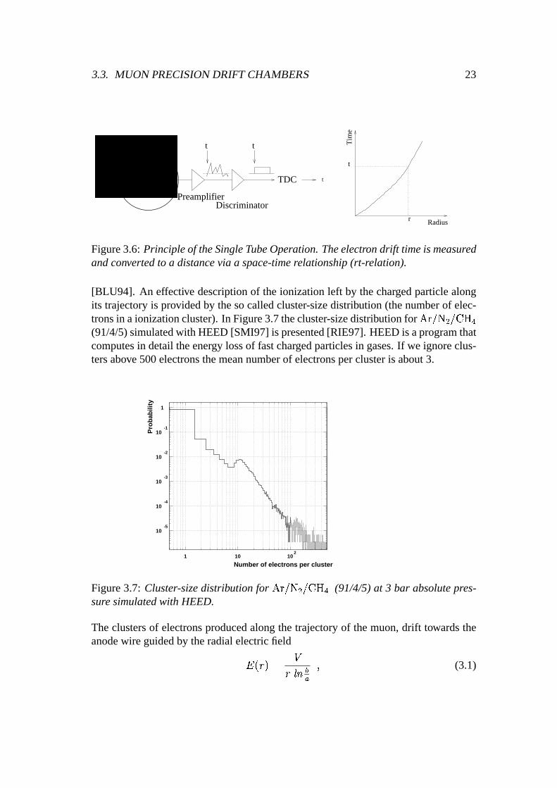
Figure3.6: Principleof theSingleTubeOperation. Theelectrondrift timeis measuredandconvertedto a distancevia a space-timerelationship(rt-relation).
[BLU94]. An effective descriptionof theionizationleft by thechargedparticlealongits trajectoryis providedby thesocalledcluster-sizedistribution (thenumberof elec-tronsin aionizationcluster).In Figure3.7thecluster-sizedistributionfor w�xy��z ü �{��| û(91/4/5)simulatedwith HEED[SMI97] is presented[RIE97]. HEEDis aprogramthatcomputesin detailtheenergy lossof fastchargedparticlesin gases.If we ignoreclus-tersabove500electronsthemeannumberof electronsperclusteris about3.
10-5
10-4
10-3
10-2
10-1
1
1 10 102
Number of electrons per cluster
Pro
bab
ility
Figure3.7: Cluster-sizedistribution for w}x~��z ü ����| û (91/4/5)at 3 bar absolutepres-suresimulatedwith HEED.
Theclustersof electronsproducedalongthetrajectoryof themuon,drift towardstheanodewire guidedby theradialelectricfield
� !\��&�� ��������� N (3.1)

24 CHAPTER3. THE ATLAS MUON SPECTROMETER
wherea is thewire radius,b theinnercathoderadiusandV thehighvoltageappliedtotheanode.As thechargeapproachesthewire, it is multiplied in anavalancheprocesscreatingnew electron-ionpairs[SAU77]. The anodevoltageis chosensuchthat theavalancheamplificationfactor (gasgain) is 2 ù 10û . Typically this voltageis about3 kV. Thepositive ion cloudmovesfrom theavalanchezonetowardsthecathode,in-ducinga currentsignal in the anodewire, which is readout on the sideof the tube,amplified,shapedandpresentedfinally to a discriminator. Thedrifting electronsalsoinducea signalwhich is thoughnegligible comparedto the ion signal. The logicaloutputpulseof thediscriminatoris givento aTime-to-Digital-Converter(TDC) whichmeasuresthe time differencebetweenthemuonpulseanda triggersignal. This timedifferenceis thedrift timeof theelectronsplusaconstantoffsetdueto thesignalprop-agationtime in theelectronics.Subsequentlythedrift time is convertedinto theradius(r) of closestapproachof the trackusingthe space-timerelationship(r-t relationshipor rt relation)obtainedby anautocalibrationprocedure[CRE97, DEI00,VIE96]. Ac-cordingto theATLAS specificationsthesingle-tubespatialresolutionshouldbe80 ø mor better. Thedetailedanalysisof thecontributionsto thespatialresolutionthatcanbeobtainedwith suchadrift tubeis discussedin [RIE97].
3.3.2 Monitor edDrift TubeChambers(MDTs)
TheMDT chambersconsistof two multilayersof tubesgluedon eithersideof a rigidspacerstructure(Figure3.8).
Longitudinal beam
In-plane alignment
Multilayer
Cross plate
y
x
z
Figure3.8: An MDT chamberconsistsof three(asshownin thefigure) or four layersof aluminumtubeswhich aregluedoneithersideof thespacerstructure.

3.4. MUON SPECTROMETERPERFORMANCEREQUIREMENTS 25
The multilayersof the chambersin the middle andouterstationhave threelayersoftubeswhile thoseof thechambersin theinnerstationhavefour layersin orderto makethe patternrecognitionin thesehigh backgroundregionsmorereliable. The supportframe(consistedof threecross-platesandtwo long beams)provide thepositioningofthe two multilayerswith respectto eachotherandmechanicalintegrity undereffectsof temperaturechangeandgravity. It alsosupportsmost of the componentsof thealignmentsystem(seesection3.5).
Theaccuratepositioningof thedrift tubesis providedby theassemblyprocedure.Thetubesaregluedtogetherafterpositioning.This chamberassemblyandconstruc-tion designwas chosenfor guaranteeingthe reliability and the stability of the con-structionandoperationfor theanticipatedlifetime of theexperimentin an irradiatedenvironment:5 yearsof storagefollowedby final assemblyand10yearsof running.
Dependingon their sizesand position in the muon spectrometer, thereare sev-eral kindsof MDT ChamberssuchasBOS(BarrelOuterSmall),BOL (BarrelOuterLarge),BIS (BarrelInnerSmall)etc.
The MDT project is on the scaleof a very large industrial project. The task innumbersis impressive: the total numberof MDTs is 1194covering an areaof 5500mü while the total numberof readoutchannelsis 371488andthe total lengthof thetubesis 1141km. The chamberswill be built in 16 Institutesspreadover the worldwith CERNcoordinationandcontrol. A Quality AssurancePlanwasestablished(seechapter4).
3.4 Muon SpectrometerPerformanceRequirements
A comparisonbetweenmostspectrometersin highenergy physicsexperimentsto dateandtheATLAS muonspectrometeryields that the latter is uniquein severalaspects.It is designedto maintainhigh performancein termsof momentumresolutionandreconstructionefficiency.
3.4.1 Momentum Resolution
Themuonspectrometerinstrumentationintendsto achieve a momentumresolutionof��HJI���HJI�� 1 ù 10� û ù�H4� GeV for HJI�X 300 GeV. Thereforeits resolutionfor themostenergeticmuonsthatareexpectedatLHC (1 TeV) will beabout10� . Figure3.9showstheindividualcontributionsto themomentumresolution;single-wireresolution,chambermisalignment,multiple scatteringandenergy-lossfluctuations.It is obviousthat for low energy muonsthemomentumresolutionis limited by multiple scatteringof themuonsin thespectrometermaterial. For high energeticmuonsthemomentumresolutionis limited by alignmenterrorsandMDT resolutionwhich wasassumedtobe80 ø m for thissimulation.

26 CHAPTER3. THE ATLAS MUON SPECTROMETER
0
1
2
3�45�67
8�9�10
11
12
10 102
103�
pT� (GeV)
Con
trib
utio
n to
res
olut
ion
(%)
T�
ube resolution and autocalibration Chamber alignment �Multiple scattering Energy loss fluctuations Total |η| < 1.5
Figure3.9: Contributionsto the momentumresolutionas a functionof HJI , averagedover � ��� 1.5.
3.4.2 ReconstructionEfficiency
The reconstruction(or pattern-recognition)efficiency is definedas the efficiency toreconstructmuontrackscorrectly. Thehighbackgroundlevelsresultin largechamberoccupancies(up to 20� for a maximumdrift time of 700 ns) and hit rates(up to300kHz per tube)andput severerequirementson thesingle-tubeefficiency andratecapability. Thefractionof timewheretheMDT is occupiedby aneventi.e. theMDT isnotableto measureamuontrackis definedasoccupancy. Thefactthattheoccupancyinfluencesthe reconstructionefficiency consiststhe main argumentfor using a fastdrift gas. In Figure3.10thereconstructionefficiency andthefake trackrate(numberof wrongly reconstructedtracks)for differentbackgroundlevels andlayout schemesareshown [ATL94]. The resultsin this figure derived from a simulationwherethemaximumdrift timewasassumedto be480ns.Thebaselinegas w�xy�{��� ü (93/7)hasalongermaximumdrift time (seesection5.2.1).

3.5. ALIGNMENT 27
95�
95.5�
96�
96.5�
97�
97.5�
98�
98.5�
99�
0�
1 2�
3�
4�
5�
6Background level
Rec
onst
ruct
ion
effic
ienc
y (%
)
0�0.5�1
1.5
2
2.5�3�3.5�4
Fak
e-tr
ack
rate
(%
)
444 efficiency �333 efficiency � 444 fake tracks �333 fake tracks�
Figure 3.10: Background level dependenceof the reconstructionefficiencyand thefake-track rate. A backgroundlevel of five refers to a safetyfactor of five on top ofthenominalbackgroundrateashasbeenderivedfromsimulation. ’444’ indicatesachamberconfigurationwith four layersof tubespermultilayerwhile ’333’ indicatesaconfigurationwith threelayers.
3.5 Alignment
A majorchallengeis thelargeactivesurfacearea(5500m� ) coveredby the1194MDTchamberstogetherwith the requiredmeasurementprecision. This imposesstringentrequirementsontheprecisionof eachindividualdrift tube,its alignmentrelative to theothertubesin thechamberandthealignmentof chambersrelative to eachother. Dueto the large scaleof the spectrometerand the big numberof chambers,it would beextremelydifficult to keepthegeometryof thechambersandtheir positionsstableonthescaleof the requiredtrackingaccuracy of 50 � m. Thereforea differentapproachwaschosenfor alignment;thechamberswill bepositionedonly with aprecisionof themillimeterscale.Thenthechambermovementsanddeformationswill becontrolledtoa precisionof betterthan20 � m by anelaboratedsystemof opticalalignmentbeamswhich will be monitoredconstantlyto apply the requiredcorrectionsto the positionmeasurement.This is the reasonthat thechambersarecalled‘Monitored Drift TubeChambers’(MDT).
Owingto geometricalconstraints,differentalignmentschemesareusedto monitorchamberpositionsin the barrel(projective alignment),in the end-capandthe defor-

28 CHAPTER3. THE ATLAS MUON SPECTROMETER
mationsof largechambers(in-planealignment).All alignmentsystemsarebasedonoptical straightnessmonitors. Optical beams,which traversethe active areaof theseopticalmonitorsplacedon their trajectoriesandmountedon theelementsof themuonspectrometer, areusedfor thealignmentmonitoring.
A vital ingredientto reachtherequiredprecisionfor largedetectorsurfacesis alsothedevelopmentof reliableonlinemonitoringandcalibrationprocedures.This aspectconstitutesamajorpartof this thesisandit is describedin subsequentchapters.

Chapter 4
Quality Assuranceof theMDT Chambers
The stringentrequirementsfor the chamberconstructionare derived from the per-formancerequirementsdiscussedin the previous chapter(section3.4). Herewe aresummarisingtherequirementsfor theproductionof theMDT precisionchambersthatarenecessaryto reachthedesiredprecisionof themomentumresolution:
Thewire of asingletubehasto bepositionedto 10 � m r.m.s(in projection)withrespectto a referencesurfaceon theendplugof thetube.
Theleakratefor asingletubemustbe ¡ 10¢�£ barl/s.
Thewire tension(350g) musthaveanr.m.sof ¡ 7 g.
The chambersmustbe constructedwith 20 � m mechanicalaccuracy (r.m.softherelative distancebetweenthewiresof thedrift tubes).
Themaximumallowed darkcurrentwhenthe tubeis operatedat a gasgain of2 ¤ 10¥ , shouldbe2 nA/m of tubelength.
Thesagof thewires mustbecontrollablewithin 10 � m up to a wire lengthof4 m.
Thedistancebetweenthetubecentreandthewirehastobelessthan100 � moverthewholetubelengthto limit thedeviationsfrom theidealrt-relation.Thereforethespacerstructureof thechambersmustguidethemultilayersalongthewires’length.
The internal optical alignmentsystemmountedon the spacerstructuremustmonitorthedisplacementof themiddlecross-platedueto temperaturegradientsat thefew micronlevel.
29

30 CHAPTER4. QUALITY ASSURANCEOF THE MDT CHAMBERS
Before the startof the seriesproductionof the MDT chambersin 2000,severalMDT prototypeshadbeenconstructedby differentATLAS institutes. Theseproto-typeswere testedin dedicatedtest beamsat CERN in order to assurethe requiredperformance.Oneof theseprototypes(a BOSchamber)wasbuilt in 1998at theMaxPlanckInstitutein Munichasacommoneffort of severalATLAS muoninstitutes(MPIMunich, LMU Munich andFreiburg University). The chamberhasa tubelengthof3800mm anda width of 2160mm, thelargestchamberwidth in thebarrelpartof theATLAS muonspectrometer. It contains432 drift tubesarrangedin two triple layers(multilayers).Eachlayercontains72 tubes.
In the following sectionsof this chapterwe will introducethe quality assuranceproceduresandtestfacilitiesusedfor theevaluationof this prototypechamber. Thesesame(with maybeminor variations)testingmethodsarecurrentlyusedfor thequalityassuranceof theMDT chambers.
4.1 Quality Control for the SingleDrift Tubes
Beforetheassemblyof thedrift tubesin a chamber, extensive quality assurancetestsof the tubesare required[ATL97]; oncea drift tube is a part of an MDT chamber,a replacementbecomesimpossible. The quality of the individual tubeshasa directimpacton the chamberperformance.Thereforea carefulvalidationof the tubeper-formanceis anintegral partof thechamberconstruction.At theLudwig-MaximiliansUniversity (LMU) in Munich we have developeda testfacility which providesa fastresponseduringdrift tubefabricationwhethereachindividual tubecorrespondsto thespecificationsconcerningwire tension,leak rate,wire location,noiserateandsignalresponse.In a first stepthis facility providedfeed-backfor a productionof about500drift tubes,which werefabricatedby theMax-Planck-Institute(MPI) in Munich, andfor thedevelopmentof tubemassproduction.
Themostcritical itemof adrift tubearetheend-plugs.They provide theelectricalcontactto the wire andhold the mechanicalwire tension. The wire tensionmustbeknown in orderto calculatethe wire positionin betweenthe wire locatorregions,asthe wire hasa sagalongits lengthin the tubedueto gravity effects. A conventionalmethodverifying the wire tension(T) is to measurethe oscillation frequency (f) ofthegroundmodewire vibrationandto usethestandardexpressionrelatingthesetwoquantitiesto thewire density( ¦ ), thewire length(L) andthewire diameter(D) :
§©¨ ¦�ª �y«.�¬4� (4.1)
The wire tensionwasmeasuredby usinga commercialCAEN tensionmeter. It wasfoundto beequal(
¨350g) for all tubeswithin 1® rms.

4.1. QUALITY CONTROL FORTHE SINGLEDRIFT TUBES 31
Thewire positionsof thetubeshave beenmeasuredusinga pair of X-Ray sourcesanda pair CCDsfor imagerecording.The tubeis positionedrigidly into a V-groovebeingsupportedandsuckedat 4 positions.The wire locationcanthenbe calculatedfrom the projectedwire imagesobserved from two differentangles,as illustratedinFigure4.1,afterthecomparisonbetweentheshadowsof thetubewire andthoseof thefiducials.During thefirst productionphase,themeasuredpositioningaccuracy of thisfacility wasbetterthan5 � m. Beforeabsolutewire positionscanbedetermined,theset-upwascarefullycalibratedwith measurementson a drift tubemountedat several(8-16)equidistantazimuthalorientationsinto theV-groove.
CCD
Suct i onCup
MDT
Fi duci al s
x- r ays
Pump
x- r ays
Figure4.1: Schematicillustration of thewire locationmeasurementset-up.
Themeasureddisplacementsof thewires( ¯ y and ¯ x) areshown in Figure4.2. Theredcircleshave a radiusof 10,20,30 , 40 and50 � m. In Figure4.3 theprojectionsofthesameresultson they andx axisof the referenceframeareshown. SideA corre-spondsto thehighvoltagesideof thetubeandsideB correspondsto its oppositeside.Thestandarddeviationsof Gaussianfits to thewire coordinatedistributionsfrom theseX-ray measurementsare10-12 � m, compatiblewith thespecificationsof Atlas.
Theleakrateof thetubeswasmeasuredwhile they werefilled with a gasmixture°�±y²{³�´ ¥ (90/10)at3 barabsolutepressure.A smallvesselvolume(0.1 µ ) wasmountedaroundeachtubeendplug.This vesselvolumewasevacuatedusinga vacuumpumpfor about30- 40minutes.Thenafterclosingthevalvebetweenthepumpandtheves-sel, thepressureincreaseasa functionof time wasrecordedandtheleakageratewascalculated.The maximumacceptedleak rateaccordingto the Atlas specificationsis

32 CHAPTER4. QUALITY ASSURANCEOF THE MDT CHAMBERS
Ʀ
x in µ· m¸
∆y in
µm
-50
-40
-30
-20
-10
0¹10º20»30¼40½50¾
-50 -40 -30 -20 -10 0 10 20 30 40 50¾
Figure4.2: Wirecoordinates( ¯ x, ¯ y) for all tubesusedfor theconstructionof oneofthefirst full sizeAtlasPrototypechamber.
51.36 / 27
Constant 57.88
Mean 9.576
Sigma 11.77
∆y in µm
39.21 / 23
Constant 61.46
Mean -3.974
Sigma 11.50
∆y in µm
36.60 / 30
Constant 68.29
Mean -8.400
Sigma 10.38
∆x in µm
28.85 / 26
Constant 72.42
Mean -4.079
Sigma 9.967
∆x in µm
0
20
40
60
-100 -80 -60 -40 -20 0 20 40 60 80 100
0
20
40
60
-100 -80 -60 -40 -20 0 20 40 60 80 100
0
20
40
60
80
-100 -80 -60 -40 -20 0 20 40 60 80 100
0
20
40
60
80
-100 -80 -60 -40 -20 0 20 40 60 80 100
Side
Side
Side
Side
A
B
A
B
Figure4.3: Wirecoordinates x and ¯ y for sideA andB of thetubes.

4.2. QUALITY ASSURANCEOF THE MDT CHAMBERS 33
10¢�¿ mbarl s¢KÀ pertube. Thesignalresponseof thetubeswasalsotested.While thetubewasfilled with gasat 3 bar absolutepressure,the naturalradiationbackground(cosmics)countrateaswell asthe countrateusinga radioactive Americium source(10 � Ci) weremeasured.During this testtheleakagecurrent(darkcurrent)of thetubewaslessthan5 nA, compatiblewith thespecifications.
In thephaseof final prototypesbeforethestart-upof thechamberproduction,thetestfacility wasalsousedfor samplesof tubesfrom otherinstitutesparticipatingin theproductionof MDT chambers(e.g. theMDT chamberfrom Frascati,Italy[CHO98]).Beforetheformal decisionof thecollaborationfor thefinal end-plugdesign,mechan-ical acceptancetestswith tubesthat haddifferentend-plugswereperformedat thisfacility atLMU asthewire positionmeasurementusingtheX-Rayset-upwastheonlyfacility of the collaborationin Europe. Besidesthe normal testsforeseenduring theproductionstage,we alsomeasuredoperationalcharacteristicsandthe leakagetight-nessof eachtubeafter repeatedchangesof the gaspressureand the environmentaltemperatureof the tubesand after inducing vibrationson the wire, thus simulatingconditionsduringthelifetime of atubeandduringtransports.Theresultsof thesetestsweretakeninto accountby theATLAS Collaborationfor theend-plugdecision.
4.2 Quality assuranceof the MDT chambers
A detaileddescriptionof thechamberconstructionispresentedin [ATL97] and[BOS98].After theassemblyof achamberextensivevalidationtestsareperformedto assurebothits mechanicalprecisionandits operationalstability.
The chambershouldbe gastight. Its leak rateis measuredandit shouldbe lessor equalto ÁÃÂ�¢�¿ mbar l/s per tube. After the front-endelectronicsis mounted,highvoltageis appliedto verify thefunctionalityof theelectronics.At this phasethedarkcurrentis alsomeasured.In additionthecorrectbehaviour of the in-planealignmentsystemis assured.
As it hasalreadybeenmentioned,theanodewiresareplacedveryaccuratelywithinthechamber(20 � m r.m.s).This demandingprecisionis anessentialingredientof theMDT conceptandneedsto be continuouslyconfirmedduring the productionphaseafter eachchamberassembly. A very elegant way to verify wire positionsinsideanassembledchamberis theuseof a largeX-Ray tomographplacedat CERN.Thishighprecisiondevice (betterthan5 � m) wasspeciallydesigned,constructedandupgradedby theATLAS Collaboration[BER98].

34 CHAPTER4. QUALITY ASSURANCEOF THE MDT CHAMBERS
Figure4.4: Photographof thelargeX-ray tomograph.
Figure4.4shows thelargeX-Ray tomographinstalledin acleanroom,whichpro-videshigh mechanicalstability andwell-controlledenvironment(seealso[DRA97]).TheX-ray tomographconsistsof:
A fixed3.5 m long iron portico,equippedwith a precisemotorizedcart rollingalongthex-axis(alongthedirectionof thewires).
Two collimatedX-Raybeamspositionedfirmly ontherolling cartataboutÄ)ÅJÁÇÆwith respectto thez-axis(thecoordinatein thechamberplane,perpendiculartothewires). Thetwo beamshave a cross-sectionof about30 � m ¤ 8 mm andadivergenceof about60 � rad.
Four high precisionlaserinterferometerswhich monitor the movementsof theX-Raysources.They recordthelineardisplacementalongthez-axis,theverticalstraightnessin the y-axis (the coordinateperpendicularto the chamberplane),the pitch angle(rotationaroundthe x-axis) andthe roll angle(rotationaroundthez-axis).
A referenceframemadeof two rulers installedabove andunderthe chamber.Therulersaremadeof two layersof a precisepatternconsistingof 60 ¤ 30 � m

4.2. QUALITY ASSURANCEOF THE MDT CHAMBERS 35
goldenstripsputonceramicplatesandmountedonacarbonfibresupport.
A rolling cartwhichsupportsandalign thechamberto bemeasured.
Onesmallmoving cartenslaved to theX-Ray cart,supportingtwo scintillators(NaI crystals)following thebeams.
Theprecisesynchronizationof the differentpartsof the X-ray tomographduringscanningaswell as the analysisof the resultsof the scansareperformedin an au-tomatedway. Critical problemsof automation(automaticalignmentof the chamber,findingpositionsof thescansalongthechamber, qualitycheckingof themeasurementsetc)arestill underdevelopmentaimingin a fully robotizedoperationof theX-ray to-mograph.
The operationalprincipal of the tomographis basedon the enhancedabsorptionof a fine, collinearX-Ray beamin the tungstenwires asopposedto the aluminiumof the tubewalls andthegas. Thechamberto bemeasuredis placedbetweentheX-ray sourcesandthe X-Ray detector(scintillators)that recordsthe absorptionprofileduring scanningalong the multilayer cross-sectionof the chamber. Scanningundertwo differentbeamangleswith respectto thechamberplane(two X-ray sources)pro-videsa stereomeasurementsuchthata two-dimensionalmapof wire positionscanbereconstructed(passive method). Every chamberis scannedin a few positionsalongthetubelength. Usingtheexternalreferenceframeof theX-Ray tomograph,a three-dimensionalmapcanfinally beconstructedallowing to measurethewire sagalongthetubes.After theanalysis,the resultsarestoredin a databaseproviding the full list ofthewire positionandaccuracy.
SeveralMDT prototypesaswell aschambersfrom theseriesproductionhavebeentestedat theX-ray tomograph.Oneof themwastheBOSprototypementionedearlierin thischapterandtheanalysisof thesedatais describedextensively in [KRO00]. It isplannedthat theX-ray tomographwill scan10 - 15® of theATLAS MDT chamberssettingupa data-basewith theirwire positions.
At the productionsitesof the ATLAS collaboration,cosmic-rayset-upsoffer thepossibilityof afull functionalitytestandcalibrationof thechambersusingcosmicrays.Sucha teststandwasbuilt in 2001by theLudwig-MaximiliansUniversity (LMU) inMunich. It is devotedto thequalitycontrolof 88BOSchambersfor theATLAS muonspectrometerthatarebeingbuilt atMPI Munich.
Thecosmicray muonteststandconsistsof a permanentpart andchambersto betested. The permanentpart consistsof two MDT referencechambers,measuredattheX-ray tomographat CERN.Below the lower MDT referencechamberthereis anabsorberconsistingof a layer of solid iron 34 cm thick. Below that iron absorberis
36 CHAPTER4. QUALITY ASSURANCEOF THE MDT CHAMBERS
a hodoscopewith a time resolutionbetterthan800pswith thecountersorientedper-pendicularto the MDT tubes. Below the hodoscopeis one layer of streamertubes,giving a spatial resolutionof about5 mm with tubesorientedparallel to the MDTtubesandplacedabout1 m below theabsorber. Above thetop MDT referencecham-ber is anotherhodoscopemadeof scintillatorsthat areorientedperpendicularto theMDT tubes. The chambersto be testedarepositionedin betweenthe two referencechambers.Theset-upoffersthefollowing possibilities:
Testof asinglechamberwith anangle01(possiblyalso22.5or 67.5degrees,i.e.in thepositiontheBOSchamberswill bemountedin ATLAS).
Testof severalchamberssimultaneouslyat 0 degree.
Apart from thedeterminationof gasleak ratesandleakagecurrents,several veryimportantperformanceparametersof the chamberswill be testedsuchasefficiency,noiseanddrift-time spectrafor eachtube. It is furthermoreplannedto assuretheme-chanicalprecisionof the chambersby measuringthe positionof their wires relativeto thoseof the two referencechambers.Theexpectedprecisionin thedeterminationof wire positions,asderived from speciallydesignedsimulationprograms[KOR00]is 10 - 15 � m in the z-coordinatefor chamberslying flat. It is expectedto measurethewire positionsrelative to thereferencechambersin they-coordinate,thoughwithlower precision(50 � m) (seeFigure3.8for thedefinitionof thecoordinateaxes).
Moreover, muchhasbeenlearnedabouttheperformanceof chamberswhich havebeenoperatedin test beamsat CERN. Theseactivities have beenfocusedon basicqualityparameterssuchasreconstructionefficiency andspatialresolutionof precisionchambers,efficiency and timing of trigger chambersand the high-ratebehaviour ofall muondetectors.Theexperienceandoutcomeobtainedduringtheseactivities havedirectly influencedthe chamberconstruction.The main ATLAS testbeamfacility istheCERNH8 beamline.At this testbeamtheBOSprototypewastestedin summerof1998andautumnof 1999(seechapter5).
It is obvious that a lot of effort is beingput from the ATLAS Collaborationintotheassuranceof therequiredmechanicalaccuracy of theMDT chambers.Thepresentthesiscontributesin this effort, asit will bedescribedin thesubsequentchapters.
1i.e. thetubelayersof thechamberareplacedparallelto thegroundplane.

Chapter 5
Calibration of the wir epositionsof aBOS Chamber
The studiesin this chapterrefer to the datataken with the full scaleprototypeMDTchambermentionedin chapter4. Thechamberhasa lengthof 3800mm, a width of2160mm andconsistsof two triple layers(multilayers)of drift tubes. It wastrans-portedto CERNandwasscannedby theATLAS X-ray tomograph(section4.2). Theresultsof thetomographrevealedthatthechamberfulfills thespecifications(mechani-calaccuracy of 20 � m). After thescan,carefulevaluationof thechamberperformancewascarriedoutin August1998andSeptember1999atahighenergeticmuontestbeamat CERN.It is necessaryto emphasizethefact thatduringthe1998teststhechamberwasfilled with
°}±~²�È � ²�³�´ ¥ (91/4/5)whereasduring the1999testsit wasfilled with°�±y²{³�É � (93/7). The reasonfor this changewill be given in a following section. Inthis chapterthe experimentalset-upsusedfor this evaluationaswell asa methodtocalibratethe positionsof the wires of this BOS chamberwithout usingany externalreferenceframearedescribed.The correctnessof our resultshasbeenverified by acomparisonwith the resultsgiven by the X-ray tomograph.This comparisonis alsopresentedin this chapter.
5.1 Set-upfor the ÊÌËKÍÏÎÑÐÒÍ�ÓÑÔÖÕ Measurements
The first evaluationandextensive testsof the above mentionedfirst BOS prototypetook placein August1998 in the H8 muon test beamat CERN. The energy of themuonbeamwas180GeV. Theexperimentalset-upis shown in Figure5.1.Thecham-berwasinstalledwith thetubesin verticalposition.A 10 ¤ 10cm� scintillatortrigger,placedat thecenterof thebeamprofile, wasusedproviding thereferencetime of theMDT tubes. ‘ODYSSEUS’ [DEI99], asshown in the samefigure, is a Silicon Mi-crostripTracker which wasusedasexternalreferencesystem.It is a beamtelescopethatcanperformreliablemeasurementsof drift timetuberesolutionandefficiency andcanverify unambiguouslyreconstructedtracksthroughchamberprototypes.Thesix
37

38CHAPTER5. CALIBRATION OFTHEWIREPOSITIONSOFA BOSCHAMBER
siliconmicrostripdetectors(5.1 ¤ 5.1cm� ) thatconsistODYSSEUShavearesolutionof 7 � m each.Fouroutof thesix planesmeasuretheprecisioncoordinateperpendicu-lar to theMDT wires,theothertwo detectorsgive usthe‘second’coordinateparallelto thewires.
Thechamberwasfilled with°}±~²�È � ²{³�´ ¥ (91/4/5)at 3 barabsolutepressure.Its
tubeswereoperatedin proportionalmodeat 3270 Volts in order to accomplishtherequiredgasgain of 2 ¤ 10¥ . Theread-outelectronicsusedwereBNL preamplifiers[BNL73], shapers(with apeakingtimeof 15ns)anddiscriminators(with aneffectivethresholdof 25primaryelectrons)andTMC TDCs[KEK] with abin width of 781ps.
BOS
BEAM
1st 2nd Multilayer
ODYSSEUS
10X10 trigger scintillator
Figure5.1: Experimentalset-upin August1998with°}±~²�È � ²{³�´ ¥ . ODYSSEUSwas
placedat the position indicatedonly whenit was usedfor the measurementof thechamberresolutionandthert-relationfor thespecificgasmixture.

5.1. SET-UPFORTHE°Ø×�²�È � ²{³�´ ¥ MEASUREMENTS 39
5.1.1 Aligning the Drift Time Spectra
A crucialparameterto determinethehit positionin spacefrom thetime measuredbytheTDC is theoffset ÙÛÚ of eachindividual tube,i.e. theTDC responsefor a null driftpath. Thetime ÙÛÚ is differentfor eachchannelandis determinedby thedelaysof thesignalcablesandthefront-endelectronics.
Thetime ÙÛÚ canbemeasuredfor eachtubeby analyzingtheraw time distributionof thehits (drift timespectrum).In Figure5.2a typicaldrift timespectrumwhile usingthe°}±~²�È � ²{³�´ ¥ gasmixtureis shown. Theleadingedgeof sucha distribution canbe
determinedby fitting thewholespectrumwith thefollowing function[CRE97]:
ÜÞÝ Ùàßâáäã Àå ã �.æJç Á å ã è æêéÇë�ì Ýyí�î ¢ðïí�ñ ß(òç Á å-éÇë�ì Ý í�î ¢ðïí�ó ßÛò æ ç Á åÖé%ë�ì Ý ïô¢ í�õí�ö ß(ò (5.1)
0
50
100
150
200
0 200 400
Drift Time (ns)
Eve
nts
Figure5.2: Thedrift timespectrumfor a typical tubefor the°�±y²�È � ²{³�´ ¥ (91/4/5)gas
mixture. Thefittedfunctioncurveis alsovisible.
whereÜÞÝ Ùàß is the numberof hits in eachtime interval and ã�÷ ( ø =1,..,8)are the pa-
rametersthatarefitted for eachtube. ã À and ã � representtheamountsof theconstantuncorrelatedbackgroundcomingmainly from theelectronicnoiseandof the truehit

40CHAPTER5. CALIBRATION OFTHEWIREPOSITIONSOFA BOSCHAMBER
distribution. ã è and ã ¿ describethenon-uniformpeakof thedistribution whereasãúùand ã ¥ correspondto theminimumandmaximumdrift time respectively. Finally theparametersã+û and ã £ describetheshapeof theleadingandtrailing edges.
Oncetheparametersareobtainedfrom thefit, the ÙÛÚ is definedasthevalueof theparameterãúù . This valuecorrespondsto the point wherethe Fermi function of thenumeratorin (5.1), that is fitted at theleadingedge,changescurvature.Finally this ÙÛÚvalueis usedasa correctionfor thedrift timeof eachhit thattheTDC gives.
5.1.2 The Least-SquaresTrack ReconstructionTechnique
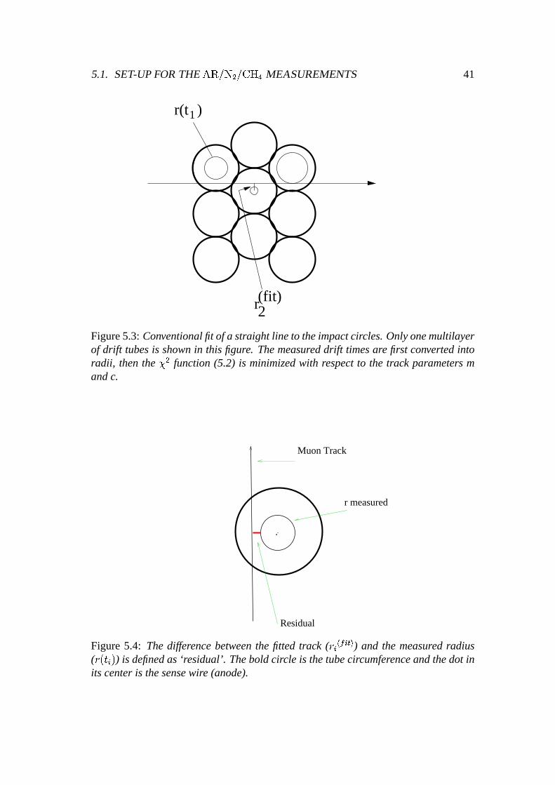
As it wasdescribedin Section3.3.1,the drift time of the electronsfrom the track ofthemuon,which traversesthedrift tube,to thewire is convertedinto aradius(r) of theimpactcircle usingthespace-timerelationship(rt relation).A muontrackcanthenbereconstructedthroughbothmultilayersof theMDT chamberby fitting a straightlineto theimpactcircles.For our analysisthis wasdoneby minimizationof thefollowingfunction:
ü � áþý4ÿ�� ����÷�� À á ç �
Ý Ù(÷ôß � ÷��� ÷���� ò �� ÷ � (5.2)
whereÜ�� ÷�����á 6 asonly trackswith six hits (onehit on eachof the six layersof the
chamber)wereusedand � ÷ is the singlewire resolutionof the ø � � tubeat the radius� ÷��� ÷���� , asmeasuredwith an external referencesystem. The hit radii � Ý Ù(÷ôß definetheimpactcircles(calculatedfrom the rt-relation)and � ÷��� ÷���� is the shortestdistancebe-tweenthe reconstructedtrack ��á�� æ�� å�� and the ø � � wire representedby a pointwith coordinates( %÷"!#�÷ ) (Figure5.3),thatis :
� ÷ �� ÷���� á%$ & æ Ç÷ å(' )#�÷ $* Á å & � (5.3)
A quantitythatwill beusedextensively in thefollowing sectionsis the‘residual’.As it is demonstratedin Figure5.4,thedifferencebetweenthefittedmuontrack( � ÷��� ÷���� )andthemeasuredradius( � Ý Ù(÷#ß ) is definedas‘residual’:
+-,/. ø"02143�µá � ÷ �� ÷���� � Ý Ù(÷ôß (5.4)
5.1. SET-UPFORTHE°Ø×�²�È � ²{³�´ ¥ MEASUREMENTS 41
r(t1)
r(fit)2
Figure5.3: Conventionalfit of a straight line to theimpactcircles.Onlyonemultilayerof drift tubesis shownin this figure. Themeasureddrift timesare first convertedintoradii, thenthe ü � function(5.2) is minimizedwith respectto the track parameters mandc.
.
Residual
r measured
Muon Track
Figure5.4: Thedifferencebetweenthe fitted track ( � ÷��� ÷���� ) and the measured radius( � Ý Ù(÷#ß ) is definedas‘residual’.Theboldcircle is thetubecircumferenceandthedot inits centeris thesensewire (anode).
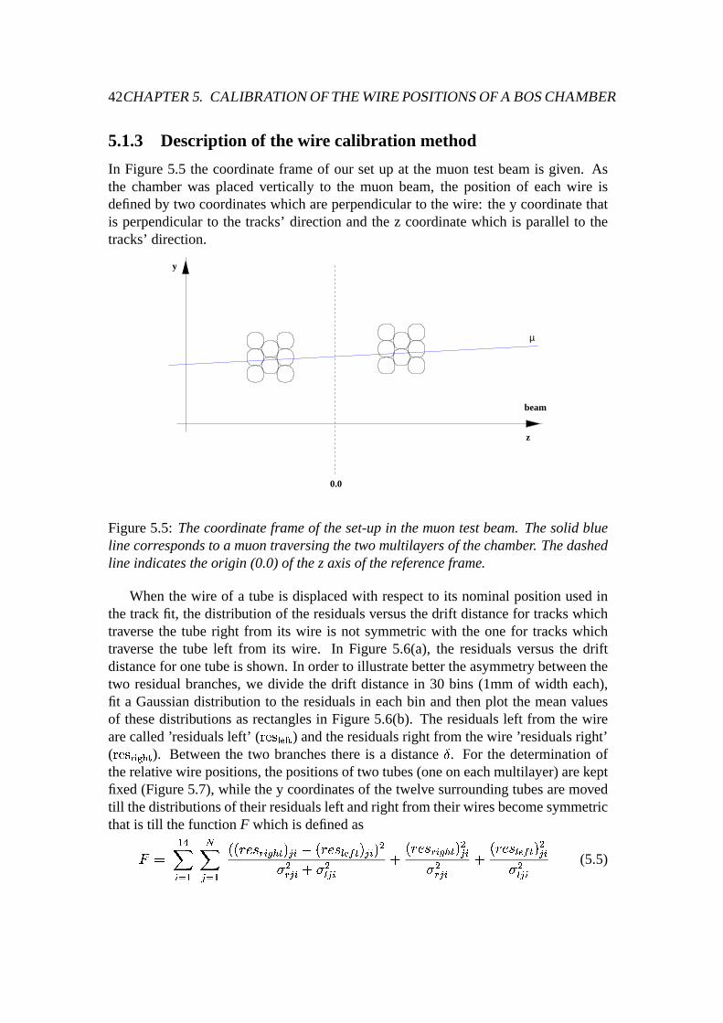
42CHAPTER5. CALIBRATION OFTHEWIREPOSITIONSOFA BOSCHAMBER
5.1.3 Description of the wir ecalibration method
In Figure5.5 the coordinateframeof our setup at the muontestbeamis given. Asthe chamberwas placedvertically to the muon beam,the position of eachwire isdefinedby two coordinateswhich areperpendicularto thewire: they coordinatethatis perpendicularto the tracks’ directionandthe z coordinatewhich is parallel to thetracks’direction.
0.0
z
y
beam
µ
Figure5.5: Thecoordinateframeof theset-upin themuontestbeam.Thesolid blueline correspondsto a muontraversingthetwomultilayers of thechamber. Thedashedline indicatestheorigin (0.0)of thez axisof thereferenceframe.
Whenthe wire of a tubeis displacedwith respectto its nominalpositionusedinthetrackfit, thedistribution of theresidualsversusthedrift distancefor trackswhichtraversethe tuberight from its wire is not symmetricwith the onefor trackswhichtraversethe tube left from its wire. In Figure 5.6(a), the residualsversusthe driftdistancefor onetubeis shown. In orderto illustratebettertheasymmetrybetweenthetwo residualbranches,we divide the drift distancein 30 bins (1mm of width each),fit a Gaussiandistribution to the residualsin eachbin andthenplot the meanvaluesof thesedistributionsasrectanglesin Figure5.6(b). The residualsleft from the wirearecalled’residualsleft’ (
± é6587:9<; ï ) andtheresidualsright from thewire ’residualsright’(± é658=�>:?A@ ï ). Betweenthe two branchesthereis a distanceB . For the determinationof
therelativewire positions,thepositionsof two tubes(oneoneachmultilayer)arekeptfixed(Figure5.7),while they coordinatesof thetwelve surroundingtubesaremovedtill thedistributionsof their residualsleft andright from theirwiresbecomesymmetricthatis till thefunctionF which is definedasC á À ¥�
÷�� À ý� D � À
ÝPÝ � ,/.FE ÷�G � �(ßD÷4 Ý � ,/.IHKJ �(ß
D÷ ßML� LE D ÷ å � LH D ÷ å
Ý � ,/.FE ÷�G � �(ßALD÷� LE D ÷ å
Ý � ,/.6HKJ �(ßALD÷� LH D ÷ (5.5)

5.1. SET-UPFORTHE°Ø×�²�È L ²{³�´ ¥ MEASUREMENTS 43
is minimized.The � E and � H arethestandarddeviationsof thedistributionof theresid-ualsright andleft from thetubewire respectively. Thefirst sumis overthegroupof the14tubeswhich is called’a flowerpair’ while thesecondis overall theresidualsvalues(N) of thebranches.Thelasttwo termsof theabovefunctionoffer extraconstraintssothatthewidth of theresiduals,whenthey areprojectedon they axisof Figure5.6b,isminimumandcenteredat zero.
-1
-0.5
0
0.5N
1
-15 -10 -5 0 5 10 15
Drift Distance (mm)O
Res
idua
ls (
mm
)
(a)
-0.1
-0.05
0
0.05
0.1N
-15 -10 -5 0N
5P
10 15-0.1
-0.05
0
0.05
0.1N
-15 -10 -5 0N
5P
10 15
resrightQ =
= resleftR
δS
Drift Distance (mm)O
Res
idua
ls (
mm
)
(b)
Figure 5.6: (a) Residualsdistribution versus the drift distancein a tube while thechamberwasfilled with
°�±~²�È L ²{³�´ ¥ (91/4/5). (b) Residualsdistribution asymmetryfor trackstraversingthewire fromleft andright. Theerror bars which are verysmallto bevisiblein mostof thepointsexpressthestandard error of themeanvaluein eachbin. Thedistancebetweenthetwo branchesof theresidualsis indicated( B ).
It is worthwhilementioningthat in this procedurewe do not take into accounttheresidualsthat arecloserthan2 mm to the wire andcloserthan1 mm to the wall. Itis alsoobvious in Figure5.6 that thereis a larger spreadof the residualscloseto thewire. Very closeto the wire the spatialresolutionof the tubeworsensasa resultofelectronclusterpositionfluctuations[DEI98] andchargefluctuations.Moreover nearthewall theMDT startsbecominginefficient [RIE97a]. Thereasonfor thatis thefactthatnearthewall the track lengthwithin the gasvolumebecomesshortandin somecasestheprimaryionizationis toosmallfor obtainingapulsegreaterthanthediscrim-inatorthreshold.
After finding thenew wire positionstheasymmetryof theresidualsleft andrightof thewire disappears(Figure5.8).

44CHAPTER5. CALIBRATION OFTHEWIREPOSITIONSOFA BOSCHAMBER
...
.. .
. ..
...
.
.
A flower pair
y
z
Figure5.7: A crosssectionof thechamberis shown.Thetubesindicatedin bluearethe two central tubes(one on each multilayer) whosewire positionsare kept fixed.Thesurroundingtubesindicatedin red,are theoneswhosewire positionsare variedsimultaneouslytill theasymmetryof theresidualsleft andright of thewiresdisappears.
-0.15
-0.1
-0.05
0T0.05
T 0.1T0.15T
-15 -10 -5 0T
5U
10V
15V
Drift Distance (mm)
Res
idua
ls (
mm
)
Figure5.8: Afterfindingthenew wirepositionstheasymmetryof theresidualsleft andright of thewire disappears. Theblack rectanglesare theresidualsbefore findingthewirepositionsandtheredtrianglescorrespondto theresidualsafter thecalibrationofthewirepositions.
It shouldbepointedout thatthisfinal form of theminimizationfunction (5.5)wasobtainedafterseveral stepsof optimization. Initially we wereminimizing the rmsof

5.1. SET-UPFORTHE°Ø×�²�È L ²{³�´ ¥ MEASUREMENTS 45
theresidualdistributionsleft andright from thewire together. Laterwe usedonly thefirst termof the(5.5). Thesetwo approachesresultedin a not sostableminimizationproceduremainly becauseof the presenceof the half illuminated tubes,that is thetubeswithin theflower pair thatare’illuminated’ with tracksonly alonghalf of theirdiameter. Thesetubeshave only oneresidualbranchandnot two asit will beshownmoredetailedin section6.1.1. Thereforethe absenceof the last two termsin (5.5)could not provide the necessaryconstraintsin order to incorporatefully thesehalfilluminatedtubesinto theminimizationprocedure.
5.1.4 Resultsand Comparisonwith the X-ray Tomograph
Thert-relationthatweusedin ouranalysisfor the1998datawastheonefor°�±~²�È L ²{³�´ ¥
(91/4/5)thatwascalculated(by autocalibrationandtheuseof externalreferencesys-tem) during testbeammeasurementsin the previous years[ALE99a] (seealsoFig-ure5.14(a)).
As thetriggerusedin ourset-upwasquitesmall(10 ¤ 10cmL ), thewire calibrationmethodwasdevelopedwhile analysingthedatatakenby only asmallgroupof 14tubes(oneflower pair). Thetotal numberof six-hit tracksthatwereusedin this flower pairwasabout60000.After applyingthemethodto thisflowerpair, wemeasuredthewiredisplacementsin the y directionwith respectto the ideal grid to have a distributionwith an rms of
¨19 � m (Figure5.9). This result is in agreementwith the required
mechanicalaccuracy of 20 � m with which thechamberwasbuilt.
0T1V2W3X
-0.04 -0.02 0T
0.02T
0.04T
EntriesMeanYRMS
12-0.5833E-02 0.1897E-01
∆yZ tbeam[ (mm)
Ent
ries/
0.00
5
Figure5.9: Wiredisplacementsin they directionwith respectto theidealwiregrid forthe12 tubesof oneflowerpair (data1998). Thermsof thedistribution (19 � m) is inagreementwith therequiredmechanicalaccuracyof thechamber(20 � m).

46CHAPTER5. CALIBRATION OFTHEWIREPOSITIONSOFA BOSCHAMBER
Thenext stepin orderto verify thereliability of themethod,wasto comparetheseresultswith thoseprovidedby theX-ray tomograph.ThetomographscannedtheBOSchamberin severalpositionsalongits full length.As thebeampositionduringourteststraversedthechamberin its middle,thetomographscanthatweusedfor ourcompari-sonwastheonethatwasperformedin themiddleof thechamber1. Figure5.10showstheshift mapof thisscanin theX-ray tomographreferenceframe.
The comparisonbetweenour resultsandthoseof the tomographrevealeda nicecorrelation(Figure5.11) andshowed that the accuracy of the methodis betterthan10� m (Figure5.12).
mu
n9
8_
3_
r4_
16
. BO
S M
arch
98
me
asu
rem
en
ts.
0
25
0
50
0
75
0
10
00
12
50
15
00
17
50
20
00
-60
0-4
00
-20
00
20
04
00
\6
00
98
/05
/13
20
.46
Ch
am
be
r wire
shifts m
ap
-Y (R
eve
rsed
!)
+Z
Figure 5.10: TheX-ray tomograph shift map of the scan �^]`_ba2c Å ± Õ Á6d . Thedis-placementsare shownin directionandamplitudefor each wire of theBOSprototypechamber. All valuesare in mm.Manywiresarehiddenby thechambercrossplates.
1According to the X-ray tomographabbreviation this scanwasnamedas egf/hjilk m n�o prq , where3 indicatesthat the scanwasin the middle of the chamber, r4 indicatesthat the chamberwasturnedby 180aroundverticalaxis (original orientation)and16 is just theconsequentnumberof scanduringmeasurements.

5.1. SET-UPFORTHE°Ø×�²�È L ²{³�´ ¥ MEASUREMENTS 47
-0.04
-0.02
0T0.02
T0.04T
-0.04 -0.02 0T
0.02T
0.04T
∆yZ tbeam[ (mm)
∆yxr
ays (mm)
Figure5.11: Thedisplacementsof the y coordinatesof the wire positionsfrom theirnominalpositionsfor the12tubesof theflowerpair measuredbytheX-Raytomograph( ¯t#ju E"vMw ) versus the correspondingdisplacements( ¯^#x��y J<vMz ) found with the methoddiscussed.Theerror bars for the tomograph pointsare equal to 5 � m while thoseof the calibration methodare 9 � m (as shownin the Figure 5.12 both resultsagreewithin 10 � m).
0T1
2
3X
-0.04 -0.02 0T
0.02T
0.04T
EntriesMeanRMS
12 0.7917E-02 0.1089E-01
∆{
yZ tbeam[ -∆
{yZ xray (mm)
Ent
ries/
0.00
5
Figure5.12: TheRMSof 10 � m of the distribution of the difference ¯^#x��y J<vMz - ¯^#ju E"vMwshowsthat theaccuracyof themethodis betterthan10 � m.

48CHAPTER5. CALIBRATION OFTHEWIREPOSITIONSOFA BOSCHAMBER
5.2 Set-upfor the ÊÌËJÍ�Ó(| Ð Measurements
After the successof the calibrationmethodto find the wire displacementsin the ydirectionfor twelve tubes,it wasdecidedthatdatafrom a biggerareaof thechambershouldbe taken in order to test the validity of the methodfor a completechamber.This planwascarriedout duringthe1999testbeamperiod. Theexperimentalset-upis shown in Figure 5.13.Thebeamenergy was300GeV.
BOS
BEAM
1st 2nd Multilayer
ODYSSEUS
Hodoscope Trigger
Figure5.13:TheExperimentalset-upin September1999with }�~l�2���-� .A largehodoscopetrigger(1 � 1 m� ) consistingof 12 scintillatorswasused.The
chamberwas filled with }�~��2����� (93/7) at 3 bar absolutepressure.Its tubeswereoperatedin proportionalmodeat 3080Volts correspondingto a gasgain of 2 � 10� .Theread-outelectronicsusedwereagain BNL preamplifiers,shapers(with a peakingtimeof 15ns)anddiscriminators(with aneffective thresholdof 25primaryelectrons).TDCsof theKLOE Experiment[VEN95] with 1.042nsbinswereusedfor thehit-timemeasurement.
5.2.1 The Gaschoice
The gaschoiceis oneof the mostcritical issuesfor the MDT system.The favouritegasmixturecandidateuntil thesummerof 1998wasthe }�~��j�����2��� � (91/4/5). It waschosendue to its very linear rt relation (seeFigure 5.14(a)),the high drift velocity

5.2. SET-UPFORTHE }����2����� MEASUREMENTS 49
(maximumdrift time of 480ns)andthegoodspatialresolutionof typically 80 � m.
Oneof the biggestconcernsis the possibledegradationof the drift chamberper-formancedue to organic depositson the electrodes,which arecreatedby processescatalyzedby ionization.Thestrengthof theseprocesseshasbeenfoundto bepropor-tional to thechargedepositontheanode.Operatingatagasgainof 2 � 10� thechargedepositwill be0.6C/cmin 10 yearsATLAS operation.Thischargedepositcaneitherreducethe MDT performanceor even completelydestroy a tube. It hasbeenfoundin extensiveagingstudiesthatgasmixturescontainingorganiccompounds(e.g. ��� � )producethin depositson thewire andon thecathodewhichaffect theperformance.
Theformerbaselinegasmixture }�~l�x�����2��� � (91/4/5)showedstrongagingdam-age(decreaseof thepulseheight,high countrates)at already1/5 to 1/2 of thechargedepositwhich is expectedduring ten yearsof ATLAS operation [SPE98]. The newbaselinegas }�~l�2����� (93/7)showednoageingbut is slower (maximumdrift time680ns) andrathernon-linear(Figure5.14(b)). Its drift velocity dependsstronglyon thereducedelectricfield, � � , where � is theelectricfield insidethe tubeand � is thegasdensity. Due to this strongdependence,slight environmentalchanges(i.e. tempera-ture,pressureandvoltage)thatinfluenceeitherthe � or the � , affect thedrift velocityin a tubeandconsequentlythert relation.Thereforenon-lineardrift gasesshow loweroperationalstability thanthelineardrift gases.
0
100
200
300
400
500
600
700
0 2 4 6 8 10 12 14
Radius [�mm]�
Dri
ft T
ime
[ns]
(a)
0
100
200
300
400
500
600
700
0 2 4 6 8 10 12 14
Radius [�mm]�
Dri
ft T
ime
[ns]
(b)
Figure5.14: Measuredrt relations(a) for }�~l�x�����2��� � (91/4/5)and(b) for }�~l�������(93/7)at magneticfieldB=0 anda gasgainof 2 � 10� .

50CHAPTER5. CALIBRATION OFTHEWIREPOSITIONSOFA BOSCHAMBER
5.2.2 Spatial Resolutionof the chamber
The spatialresolutionof the chamberis alsodifferentfor the two differentgasmix-tures(theformerandthepresentbaselinegas).Thespatialresolutionasa functionofthedrift distance� is definedasthewidth of theresidualdistribution in discreteslicesin � [ALE99a]. The residualdistributionsareobtainedby comparingthe track posi-tion ���r�A�<�A�� ¢¡��<� , predictedby thereferencesystem(ODYSSEUS)andthetrackposition�`£¥¤�¦§�<¨ª©¥«��A�<�6¬ , measuredwith thedrift tube. In Figure5.15theresolutionasa functionof the distancer from the wire is given for both gases:(a) for }�~l�x�����2��� � (91/4/5)[ALE99b] measuredin 1997and(b) for }�~l�2����� (93/7)measuredin 1999 [KOR98].
0
25
50
75
100
125
150
175
200
225
250
0 2 4 6 8 10 12 14Track distance [
mm]®
Res
olu
tio
n [µ
m]
(a)
/µm
σ225
200
175
150
125
100
75
250
0 2 4 6 8 10 12 14r/mm
(b)
Figure 5.15: Resolutionas a function of the drift distancefrom the wire: (a) for}�~l�j���l�2��� � (91/4/5)(b) for }�~l�2���-� (93/7).
Themainreasonfor thequalitatively differentradialdependenceof theresolutionfor thetwo gasesis thehigherdiffusionin }�~l�j�����2��� � whichcausesthedeteriorationfor �°¯²± mm [RIE99]. Theaveragetuberesolution ³µ´(¯ is givenby quadraticallyaveragingthelocal resolution( ´ ) asa functionof thedrift distance,thatis:
³¶´·¯�¸ ¹º�» ¹¼(½¾ ¦¦-¿ ´§£À�Á¬� �§Ã � (5.6)
whereº
is thedrift distance.Accordingto theATLAS convention,thefirst millimeteris excludedfrom theaveragebecausenearthewire theresolutionis sobadthathits inthis rangewill oftennot betakeninto accountby trackfits throughanMDT chamber.Moreover, thequadraticaveragewouldbedominatedby thelarge ´§£À�Á¬ in thissmallin-terval andwouldnotbearepresentativenumber. Theaverageresolution(for operation

5.2. SET-UPFORTHE }����2����� MEASUREMENTS 51
without radiationbackground)asdefinedin equation(5.6) for }�~��j�����2��� � (91/4/5)is80 � m, whereasfor }�~l�2����� (93/7)is 69 � m.
5.2.3 Resultsand Comparisonwith the X-ray Tomograph
Usingthesilicon strip detectortelescope(ODYSSEUS)asexternalreferencesystem,the r-t relationshipwasdetermined.It wascompatiblewith previous testbeammea-surements(seesection5.2.1)andweusedit for analysingthedatafrom 6 flowerpairs(51 tubesin total). This time the adjustmentof only the ¤"Ä parameter, as it wasde-scribedin section 5.1.1,wasnotenough.Moreover the ¤"Ä couldnotbemeasuredwiththesameaccuracy for all tubescoveredby thelargehodoscopetrigger. As thedimen-sionsof thebeamwere7 � 7 cm� (Gaussianprofile), thetubesthatwerecloseto thecenterof thebeamhadmorehitssotheir ¤"Ä wasdeterminedwith higheraccuracy thanthetubesthatwereplacedfurtherfrom thisposition.
In orderto interpretour datain the bestpossibleway andbeingableat the sametime to measurethe positionsof the wires, in a first approachwe usedfor eachtubea differentr-t relationshipby applyingtheconventionalautocalibrationproceduresi-multaneouslyfor eachtube.During this autocalibrationwe couldonly usetracksper-pendicularto the chambersincewe did not have datasetswherethe tracksformeddifferentangleswith thechamber(asrequiredfor theautocalibrationprocedure).
The wire displacementsobtainedin this way wereconsistentwith the X-Ray to-mographmeasurements.Thisapproachthoughraisedtheimportantquestion,whethertheuseof anindividual r-t relationshipfor eachtubeis reallynecessary.
Furtherstudiesshowed however, that the tubescould be treatedwith a commonrt relationandthat the only parametersthat hadto be adjustedindividually for eachtubewerea time offset anda scaleparameter. More preciselywe fitted eachoneoftheabove rt relationsto theoneof thesilicon telescope(ODYSSEUS)usinga lineartransformation.In Figure5.16thert relationof oneof our tubes,beforeandafter thefit, is plottedtogetherwith the rt relationmeasuredby ODYSSEUS.By dividing thearea2 mm ³ r ³ 13 mm into 60 bins,we obtaintheinitial time valuefor eachoneofthem( ÅrÆ:ÇrÆ ). Consequentlywe minimizedthefollowing function:
È � ¸ ÉÊ ��Ë ¾ ¸Ì£¥¤���ÍI� » ¤" ¥Î����F¬ � (5.7)
where ¤" ÀÎ����ϸÑÐÓÒÔ¤"Î��AÕ�©×ÖµØ , ¤"Î��AÕ�© is the time valueof the specificbin given by the rtrelationdeterminedby the silicon telescopeand Ù is the numberof bins between2and13 mm. After this fitting procedurethetwo parametersÐ (scaleparameter)and Ø(time offset) aredefined. The adjustmentof thesetwo parameterscorrespondsto anadjustmentof the ¤"Ä parametertoo. Thereforethe ¤"Ä wasfinally determinedwith the

52CHAPTER5. CALIBRATION OFTHEWIREPOSITIONSOFA BOSCHAMBER
aboveprocedurewith anaccuracy of about300ps(asderivedfrom simulationstudiesthatwill bedescribedin thenext chapter).Figure 5.17shows how theasymmetryofthe residualsleft andright of thewire of oneof the tubesdisappearsaftercalibratingthewire positions.
0
200
400
600
0 2 4 6 8 10 12 14
Drift Distance (mm)
Drif
t Tim
e (n
s)
Figure5.16: Thedashedline is the rt relationmeasuredwith ODYSSEUS.Thesolidline is the rt relation for oneof the tubesbefore thefit. Thedot-dashedline is the rtrelationof thesametubeafter thefit andit is notveryvisibleasit almostoverlayswiththesolid line.
-0.1
0Ú
0.1Ú
-10 0Ú
10Û
Drift Distance (mm)
Res
idua
ls (
mm
)
Figure5.17: Residualsleft and right of the wire versusthe drift distancefor a tubewhile thechamberwasfilled with thebaselinegas }�~��2����� (93/7). Theblack rectan-glesaretheresidualsbeforefindingthewirepositionsandtheredtrianglescorrespondto theresidualsafter thecalibration of thewirepositions.

5.2. SET-UPFORTHE }����2����� MEASUREMENTS 53
Thedistributionof thewire displacementsfoundwith thisadjustmenthasanrmsof16 � m (compatibleagainwith themechanicalaccuracy of thechamber)(Figure5.18).It shouldbe mentionedalsothat thesewire displacementsarethe sameasthoseob-tainedwhile eachtubehadits own rt relation. Comparisonwith the X-ray measure-mentsof the new wire coordinatesshows again a goodcorrelation(Figure5.19)andagreementwithin 10 � m rms(Figure5.20) [CHO00].
0Ú
2.5Ü
5Ý
7.5
10Û
-0.05 0Ú
0.05Ú
EntriesMeanÞRMS
51-0.8922E-03 0.1616E-01
∆yß tbeamà (mm)
Ent
ries/
0.00
7
Figure5.18: Wire displacementsin they directionwith respectto the ideal wire gridfor the51 tubesof six flowerpairs (data1999).Thermsof thedistribution (16 � m) isagain in agreementwith therequiredmechanicalaccuracyof thechamber(20 � m).
-0.08
-0.06
-0.04
-0.02
0
0.02
0.04
0.06
0.08
-0.05 0 0.05
∆ytbeamá (mm)
∆yxr
ay (
mm
)
Figure5.19: Thedisplacementsof the y coordinatesof the wire positionsfrom theirnominalpositionsfor the 51 tubesmeasured by the X-Raytomograph ( â^#jãr�"¨MÕ ) ver-susthecorrespondingdisplacements( â^#x¡�ä¥�<¨M¦ ) foundwith themethoddiscussed.Theerror barsare thesamelike thosein Figure5.11.

54CHAPTER5. CALIBRATION OFTHEWIREPOSITIONSOFA BOSCHAMBER
0å
5æ
10
-0.04 -0.02 0å
0.02å
0.04å
EntriesçMeanèRMSé 51
-0.2500E-02 0.1071E-01
∆yê tbeam-∆yê xray (mm)
Ent
ries/
0.00
5
Figure5.20: Thedistribution of thedifferenceâtëx¡�ä¥�<¨M¦ - â^ëjãr�"¨MÕ . Thermsof thedistri-bution is about11 � m.
5.3 Summary
Using thedatatakenwith oneof thefirst full scaleMDT prototypesduring the1998testbeamperiod,while the chamberwasfilled with the former ATLAS baselinegas}�~l�j���l�2��� � (91/4/5), the relative wire positions(in the y direction) for a group oftwelve tubeswerefound usinga wire calibrationmethodthat needsno externalref-erenceframe. The accuracy of the methodwasbetterthan10 � m asderived from acomparisonof theseresultswith thoseof theX-ray tomographat CERN.Thesuccessof thesestudieswasrepeatedthefollowing yearby finding thewire positionsof fifty-onetubesof the sameprototypechamber;this time the chamberwasfilled with thenew baselinegas }�~��2����� (93/7).
Having proventhesuccessof thewire calibrationmethodfor moretubes,thesim-ulation studiesin orderto identify its statisticalandsystematiceffects,whenappliedalongthe full width of a chamber, wasthefinal stepandI amdiscussingthemin thenext chapter.

Chapter 6
Simulation studiesof the calibrationmethod
After the successfulresultsof the wire calibrationmethoddescribedin the previouschapter, simulationstudiesof its applicationalongthewholewidth of achamberwereperformed.Moreover the combinationof the informationfrom the individual flowerpairs,as it will be describedin this chapter, canprovide a morecompletetestingofthemechanicalaccuracy of thechamber. Thesystematicandstatisticaleffectsof themethodthatareintroducedby differentfactorsarealsopresented.
6.1 Simulation for individual flower pairs of a chamber
For a simulatedchamberfilled with }�~l�2����� (93/7) andhaving wire displacementsof 20 � m rmsin they direction(Figure6.1),muontracksperpendicularto thecham-berusingaGEANT [GEA93] basedsimulationprogram(MTGEANT [KOR00]) wereproduced.GEANT is a systemof detectordescriptionandsimulationtools thathelpparticlephysiciststo designandoptimizethe particledetectors,develop andtestthereconstructionandanalysisprogramsandinterprettheirexperimentaldata.Theenergyof themuonsproducedwas180GeV.
Along thewholewidth of thechamber(72tubesperlayer)thereare70overlappinggroupsof 14tubes(flowerpairs).Fromthemany thousandsmuontracksproduceddur-ing thesimulationwe used25000for eachflower pair. After applyingthemethodtoall of these70 flower pairs,the local displacements,that is therelative displacementsof thewireswithin aflowerpair, weremeasured.
At this point it is necessaryto describehow thecomparisonbetweenthedisplace-mentsof thewires foundwith this methodandthegeneratedoneswasmade.In Fig-ure6.2thereferenceframe(y,z)of thesimulatedperfectgrid of thewiresof oneflowerpair of thechamberis shown. Thenominalpositionsof thetubewiresarerepresented
55

56 CHAPTER6. SIMULATION STUDIESOFTHE CALIBRATION METHOD
asblackpoints.Perfectgrid meansthatall they pitches(separationbetweentwo suc-cessive wires in the y direction)areequalto 30.036mm while all the z pitchesareequalto 26.054mm. The distancebetweenthe two middle layersof the chamberis399.07mm. Thedistancesin thisFigurearenot in scale.
0Ú
10Û20
-100 -50 0Ú
50Ý
100Û
EntriesMeanÞRMS
432-0.3704E-01
18.68
∆yß genì (µí m)
Ent
ries
Figure6.1: Thegenerateddisplacementswith an rms of about20 � m of all the 432wiresof a wholechamber.
In the wire calibrationmethodthe wire positionsof the two centraltubesin thetwo middle layersarekept fixed (assumingthat they coincidewith the positionsoftheperfectgrid). Thedisplacementsof thesurroundingwires thatarefound,expressthe relative positionsof thesewires with respectto the real positionsof the centralones.By keepingthetwo centralwiresfixed(whosepositionsin reality arenot thoseof theperfectgrid asassumed- they arealsodisplaced)we definea new local refer-enceframewithin every flower pair. Thereforethe displacementsin the perfectgridreferenceframeshouldbetransformedinto displacementsin thelocalflowerreferenceframe.After this transformationthecomparisonbetweenthe(transformed)generatedandmeasureddisplacementscanbeperformed.
Comingbackto Figure6.2, we illustratea simpleexampleof the transformationbetweenthe two referenceframesmentioned(usingnumbersfor clarification). Sup-posethatonly thewire of oneof thetwo centraltubes(tube2) is displacedby 30 � min they direction.Theline thatconnectsthetwo centralwiresdefinesthedirectionofthez’ axisof therotatedlocalflower referenceframe.Theaxesof therotatedframey’andz’ arealsoindicated.Becausethedisplacementof tube2 is sosmall (in theorderof microns)theangleî is alsoverysmall( îï¸ñð`ò�ójôÁÒ ¹ ðöõÓ÷ Î�ø ð Î ).

6.1. SIMULATION FORINDIVIDU AL FLOWERPAIRS OF A CHAMBER 57
..
...
..
..
..
.
.
. 1 2
3
AB
z’
y’ y
z
θ
0 399.07 425.082
0
(mm)
(mm) displacedposition
30µ m = 32 µ m
.
Figure6.2: Theperfectgrid referenceframe(y,z) and the rotatedlocal flower frame(y’,z’). Theblack pointsare the nominalpositionsof the wiresof oneflower pair inthe(y,z) frame. Thebluepoint closeto wire 2 indicatesits displacedpositionin theydirection.
Given that the coordinatesof tubes2 and3 are( ë2��ùrú/� ) and( ë�û�ùrú�û ) respectively,their correspondingcoordinates( ëýü� ùrú�ü� ) (i = 2, 3) in the rotatedframeby angle î willbe:
ë ü� ¸ » ú/��þIÿ�� î�Ö ë2�����jþ�î ù ë üû ¸ » ú�û�þIÿ�� î�Ö ë�û����jþ�î (6.1)
ú ü� ¸ñú������jþ�î�Ö ë2��þIÿ�� î ù ú üû ¸ñú�û����jþ�î�Ö ë�û�þ6ÿ�� î (6.2)
By replacingsinî ¸ î , cosî ¸ 1 ( î ø ð Î ), ú/� ¸ 399,07mm, ë2��¸ 0.03mm, ú�û�¸425.082mmand ë�û�¸ 15.018mm(asdefinedby theperfectgrid) we find:
ë ü� ¸ » ð`ò ð � Ö(ð`ò ð � ¸ñð�·ù ë üû ¸ » ð`ò ð � � Ö ¹ ô ò ð ¹ � ¸ ¹ ± ò�� ��� � (6.3)
ú ü� ø ú/� ú üû ø ú6û (6.4)
Equation6.4 denotesthatAB canbeconsideredparallelto they axis. As they pitchis equalto 30.036mm,thedistancebetweenwire 2 andwire 3 is:ëI�r��¡� ��� ¸ � ð`òKð ���� ¸ ¹ ô ò ð ¹ � � (6.5)

58 CHAPTER6. SIMULATION STUDIESOFTHE CALIBRATION METHOD
Fromthesecondequationin 6.3,it is obviousthatthewire 3 will bedisplacedfrom itsnominalpositionin therotatedframeby��� ¸ ¹ ± ò�� ��� » ¹ ô ò ð ¹ � ¸ » ð`ò ð � � � (6.6)
Theminussignin theaboveequationdenotesthatthewire 3 is closerthanthenominaldistanceto thewire 2. In reality thewire 3 hasgenerateddisplacementequalto zerobut wire 2 hasgenerateddisplacementequalto 0.030mm. Our methodmeasurestherealrelative positionsbetweenthefixedtubesandthesurroundingones.Thereforeaswekeepthewire 2 fixedatpositiony = 0.0wewill measurethatthewire 3 is displacedandis closerto the wire 2 by about0.032mm. The displacementthat is found withthemethod,shouldbecomparedwith thedisplacementAB of thewire 3 in therotatedframe.
After thecorrespondencebetweeneachreferenceflower frameof thewholecham-berandtheperfectgrid oneis found,thedisplacementsof thewire positionsmeasuredwith our methodwerecomparedto thegeneratedones(Figure6.3(a)). This compar-ison revealeda local accuracy of the methodin the order of 5 � m (Figure 6.3(b)).Statisticalandsystematiccomponentsof this accuracy will be investigatedin thefol-lowing sections.
-0.1
-0.05
0�0.05
0.1�
-0.1 -0.05 0�
0.05 0.1�
∆y� rec� (mm)
∆yge
n (m
m)
(a)
0
50
100
-0.04 -0.02 0 0.02 0.04
Entries 840
15.80 / 17
Constant 115.2
Mean 0.1331E-03
Sigma 0.4571E-02
∆yrec - ∆ygen(mm)
Ent
ries/
0.00
2
(b)
Figure6.3: (a) Thegenerateddisplacementsof they coordinatesof thewire positionsfromtheir nominalpositionsfor thetubesof onesimulatedchamber( â^ë��8�ÀÍ ) versusthecorrespondingdisplacements( â^ëx�A�< ) recalculatedwith themethoddiscussed.(b) Thedistribution of thedifferenceâ^ëx�A�< - â^ë��8�ÀÍ for fixed ¤"Ä =0 ps. There are doubleentriesfor all tubesof thechamberastheflowerpairsmeasuredareoverlaid.(No of entries= (70flowerpairs) � (12measuredwires)= 840).Thedistributionhasa ´ of about5 � m.

6.1. SIMULATION FORINDIVIDU AL FLOWERPAIRS OF A CHAMBER 59
Thisprecisionis by afactortwo betterthantheoneweobtainedusingthetestbeamdata. The reasonis that the ¤"Ä parameterwas kept equalto zero in the simulation.In reality this is not thecase.This parametercanbedeterminedwith anaccuracy of200-300ps for individual tubes[RAU01]. Therefore,we introducedto thedrift timespectraof the tubes,Gaussiandistributed ¤"Ä offsetsof anrmsof 200and300psasitwill bedescribedin thenext section.
6.1.1 Systematicsdue to � �After introducingto the drift time spectraof all the tubesof the simulatedchamber,Gaussiandistributed ¤"Ä offsetsof an rms of 200ps the local uncertaintyincreasedto8 � m (Figure 6.4a). When theseoffsetshad an rms of 300psthe local uncertaintybecame9 � m. In Figure6.4b the local accuracy dependenceon the spreadof the ¤"Ävaluesis presented.
0�20
40
60
80
-0.05 -0.025 0�
0.025 0.05�
Entries!
840Constant 78.57Mean 0.1694E-03Sigma 0.8138E-02
∆y� rec� -∆y� gen" (mm)
Ent
ries/
0.00
2
(a)
0�5#
10
15
0�
100$
200 300%
400
Spread of t0 (psec)&
Loca
l acc
urac
y (µ
m)
(b)
Figure6.4: (a) Thedistributionof thedifferenceâ^ëx�A�< - â^ë��8�ÀÍ whenthe ¤"Ä hasa Gaus-sian distribution with a width of 200 ps, (b) the local accuracy dependenceon thespreadof ¤"Ä .
Themainreasonfor this effect is thepresenceof thehalf illuminatedtubesin thetwo middle layersfor eachflower pair. For thesehalf illuminatedtubeswe useonlytracksthatpasseitherright or left from theirwires,sothedistributionof their residualsversusthedrift distancehasonly onebranchandnot two (Figure6.5).
Whenthe ¤"Ä changesthe two branchesof the fully illuminated tubesaremovedtogethereitherup or down. Thedistancebetweenthemthoughstaysthesame.In the

60 CHAPTER6. SIMULATION STUDIESOFTHE CALIBRATION METHOD
caseof thehalf illuminatedtubes,their onebranchagain is movedup or down but wedonothaveany informationfor thesecondbranch.Wecannotdeterminethedistancebetweenthetwo branchesfor thesetubesandconsequentlytheinformationfor thewiredisplacementthatis expressedwith thedistancebetweenthetwo branchesis inevitablypartly lost. Accordingto our methodthesinglebranchesof thehalf illuminatedtubesarejust alignedalongthe line that correspondsto residualvaluesequalto 0 (seethetwo lasttermsof theminimizationfunctionin equation5.5).
B
A
Fully illuminated
Half illuminated Tube B
Tube A
A flower
d
0 15-15
-15 150
r (mm)
r (mm)
res
(mm
)re
s (m
m)
0
0
Figure6.5: On the left, a flower pair of tubesis shown;d indicatesthe area whosetracks we usefor this flower pair. This has as a result that four tubes(indicatedinblue) in theflowerpair are half illuminatedwith tracks. On theright of thefigure theresidualsversusthedrift distancefor the fully illuminatedtube(A) aswell as for thehalf illuminatedone(B) areshown.ThetubeA hastworesidualbranchesbut thetubeB hasonlyone.

6.1. SIMULATION FORINDIVIDU AL FLOWERPAIRS OF A CHAMBER 61
6.1.2 Statistical effects
As it was previously mentioned,for the studiesin sections6.1 and 6.1.1, we used25000muontracksperflower pair. In orderto separatestatisticalandsystematicpre-cisionof ourmethod,it wasnecessaryto examineits localaccuracy by usingdifferentnumberof tracks. The local accuracy dependenceon the numberof tracksusedisshown in Figure6.6 for thecasethatthe ¤"Ä waskeptequalto 0 andwhenit hadGaus-siandistributedvalueswith a width of 200ps.Theerrorbarsof thepointsexpressthestandarderror of the meanvalueof the accuracy that wasobtainedby repeatingtheanalysiswith severalsubsamplesof thespecificnumberof tracks.It is obviousthatformorethan10000tracksa plateauis reachedwhile for smallernumbersof tracksthelocal accuracy startsto deteriorateandreaches11 � m and13 � m for 1000tracksfor¤"Ä =0 andaspreadof ¤"Ä equalto 200psrespectively.
0Ú5Ý
10
15Û20
0Ú
10000Û
20000Ü
30000'
40000(
No of Tracks)
Loca
l acc
urac
y (µ
m)
0 psecÚ200 psecÜ
Figure6.6: Thelocal accuracy dependenceon the numberof tracks usedper flowerpair. Thecirclescorrespondto thecasewhere the ¤"Ä waskeptequalto 0 whereasthetrianglesrepresentthecaseof ¤"Ä spreadwith a width of 200ps.Theerror barsvisiblein this Figure are lessthan0.5 � m whereasfor theotherpointsthey are too small toberepresented.
Wecanconcludethatin orderto usethefull potentialof themethodatotalnumberof morethan10000tracksshouldbeusedperflowerpair. Suchanumberof trackscanbeobtainedin realLHC conditionsin about2-3 hoursof run.
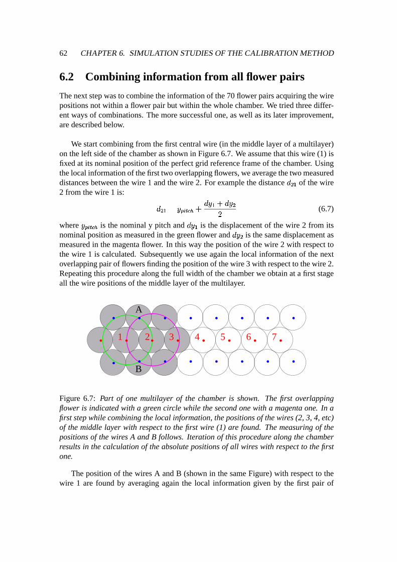
62 CHAPTER6. SIMULATION STUDIESOFTHE CALIBRATION METHOD
6.2 Combining information fr om all flower pairs
Thenext stepwasto combinetheinformationof the70flowerpairsacquiringthewirepositionsnot within a flower pair but within thewholechamber. We tried threediffer-entwaysof combinations.Themoresuccessfulone,aswell asits later improvement,aredescribedbelow.
We startcombiningfrom thefirst centralwire (in themiddlelayerof a multilayer)on theleft sideof thechamberasshown in Figure6.7. We assumethatthis wire (1) isfixedat its nominalpositionof theperfectgrid referenceframeof thechamber. Usingthelocal informationof thefirst two overlappingflowers,weaveragethetwo measureddistancesbetweenthewire 1 andthewire 2. For examplethedistanceà � ¾ of thewire2 from thewire 1 is: à � ¾ ¸ ëI�ª��¡� *��Ö Ã ë ¾ Ö Ã ë2�� (6.7)
where ëI�r��¡� �� is thenominaly pitch and Ã ë ¾ is thedisplacementof thewire 2 from itsnominalpositionasmeasuredin thegreenflower and à ë2� is thesamedisplacementasmeasuredin themagentaflower. In this way thepositionof thewire 2 with respecttothewire 1 is calculated.Subsequentlywe useagain the local informationof thenextoverlappingpairof flowersfindingthepositionof thewire 3 with respectto thewire 2.Repeatingthis procedurealongthefull width of thechamberwe obtainat a first stageall thewire positionsof themiddlelayerof themultilayer.
. . . . . .. . . . . . . .
. . . . . . ... 1 2 3 4 5 6 7.
A
B
Figure 6.7: Part of one multilayer of the chamberis shown. The first overlappingflower is indicatedwith a greencircle while thesecondonewith a magentaone. In afirststepwhilecombiningthelocal information,thepositionsof thewires(2, 3, 4, etc)of themiddlelayer with respectto thefirst wire (1) are found. Themeasuringof thepositionsof thewiresA andB follows. Iteration of this procedure alongthechamberresultsin thecalculationof theabsolutepositionsof all wireswith respectto thefirstone.
Thepositionof thewiresA andB (shown in thesameFigure)with respectto thewire 1 are found by averagingagain the local informationgiven by the first pair of

6.2. COMBINING INFORMATION FROM ALL FLOWERPAIRS 63
overlappingflowers. Iteratingalongthewholechamberwe obtaintheabsoluteposi-tionsof all thewireswith respectto thefirst centralwire ( ëj ÀÎ � ).
During this iterationof combininglocalmeasurementstheproblemwhicharisesisthe fact that the errorsareaddedup alongthe chamber. Thereforethe further is onetubefrom thefirst centraltube,theworseits positionaccuracy gets.We tried to solvethis problemby minimizing thefollowing functionG:+ ¸ ÉÊ ��Ë ¾ £Àë�,r��¡.- » ëxÍ6Î�¦/- ¬ � ù (6.8)
where ë�,r��¡.-�¸ Ð ¾10 ëj ÀÎ ��- Ö Ðý� , while Ù is the numberof the wires in onemultilayer,ëxÍ6Î ¦/- is thenominalpositionof thewire (perfectgrid), Ð ¾ is acorrectionparameterthatscalestheaveragedistancebetweentwo successivewiresand Ðý� is asecondcorrectionparameterthataccountsfor theshift of onemultilayer. Theabsolutepositionsof thewires with respectto the whole chamberthat we acquiredwith this procedurein thecasewherethedrift time spectrahadGaussiandistributed ¤"Ä offsetsof anrmsof 200psareshown in Figure6.8; theglobalaccuracy is in theorderof 20 � m.
Assumingrandomanduncorrelatedwire displacements,to get the absolutewirepositionswith respectto thewholechamber, only a smallsurroundingof eachwire isneeded.Thereforeweselectanareaof 33 tubes(10flowers)aroundeachwire andwedeterminetheshift andscaleparameters( Ð ¾ ùrÐý� ) for this specificwire by minimizingthis function: + ¸ û"ûÊ ��Ë ¾ £Àë�,r��¡.- » ëxÍ6Î�¦/- ¬ � ù (6.9)
Theglobalaccuracy now improvesto 10 � m ascanbeenseenin Figure6.9a(where´ £¥¤"ÄI¬ = 200ps). The resultsobtainedfor the globalaccuracy while usingdifferent ¤"Äoffsetsarepresentedin Figure6.9b. This local determinationof the shift andscaleparameteris justifiedif onewantsto testwhetherindividual tubesareat their nominalpositionwith respectto thesurroundingtubes.

64 CHAPTER6. SIMULATION STUDIESOFTHE CALIBRATION METHOD
0Ú5Ý
10
15Û20
-0.1 -0.05 0Ú
0.05Ú
0.1Ú
EntriesMeanÞRMS
422 0.3649E-03 0.2071E-01
34.00 / 44Constant 14.77MeanÞ
0.1613E-02Sigma 0.2205E-01
∆yß meas2 -∆yß genì (mm)
Ent
ries
Figure6.8: Determinationof theabsolutewirepositiondistributionwith respectto thewholechamberfor a ¤"Ä spreadof 200ps.
0
10$20
30%40
-0.1 -0.05 0 0.05�
0.1
Entries!
422Constant 28.82Mean3
0.6010E-03Sigma 0.1040E-01
∆yrec� -∆ygen" (mm)
Ent
ries
(a)
0
5
10$15$
0 100 2004
300 400
Spread of t0 (psec)
Acc
urac
y (µ
m)
(b)
Figure 6.9: (a) Whena small surroundingof the wire to be measured is used,theglobal accuracyimprovesto 10 � m for a ¤"Ä spreadof 200ps,(b) theglobal accuracydependenceon thespreadof ¤"Ä .
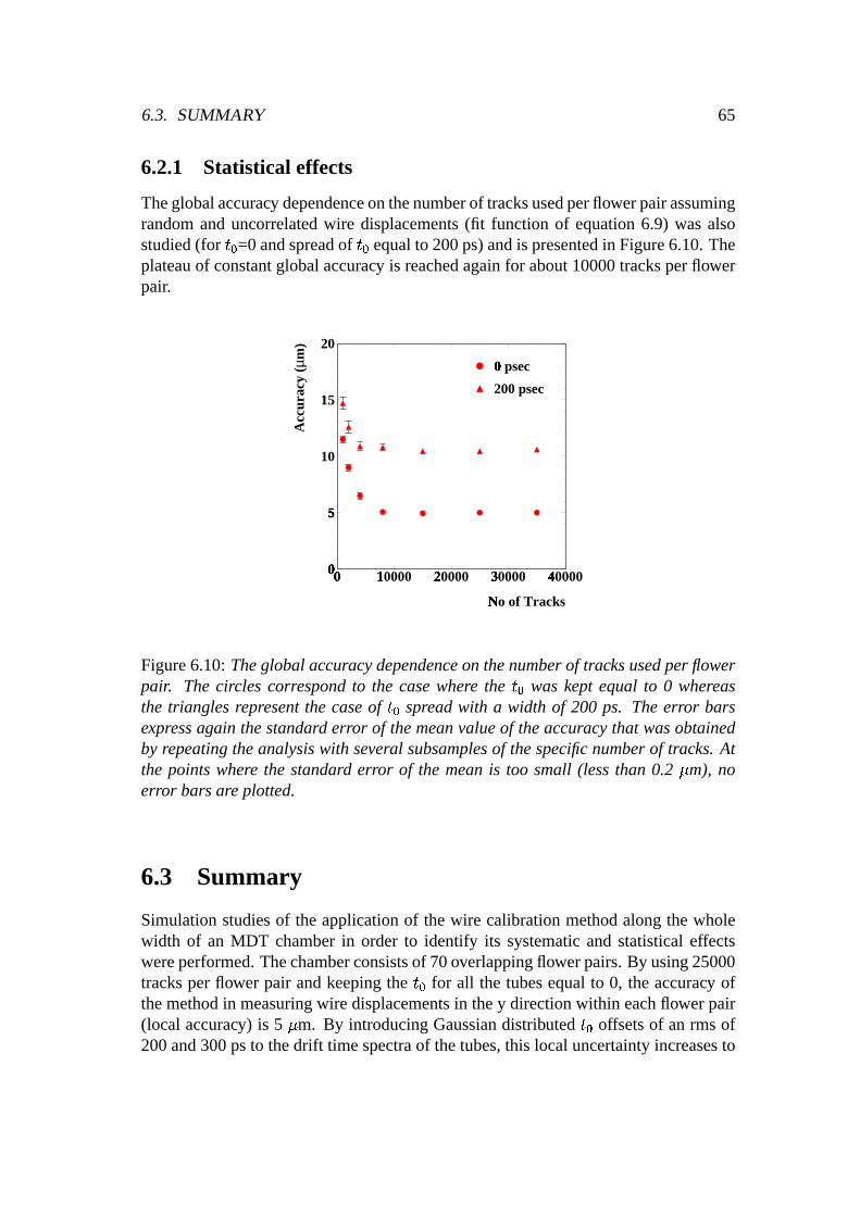
6.3. SUMMARY 65
6.2.1 Statistical effects
Theglobalaccuracy dependenceonthenumberof tracksusedperflowerpairassumingrandomanduncorrelatedwire displacements(fit function of equation6.9) wasalsostudied(for ¤"Ä =0 andspreadof ¤"Ä equalto 200ps)andis presentedin Figure6.10.Theplateauof constantglobalaccuracy is reachedagain for about10000tracksperflowerpair.
0Ú5Ý
10
15Û20
0Ú
10000Û
20000Ü
30000'
40000(
No of Tracks)
Acc
urac
y (µ
m)
0 psecÚ200 psec
Figure6.10:Theglobalaccuracydependenceon thenumberof tracksusedperflowerpair. Thecircles correspondto the casewhere the ¤"Ä was kept equal to 0 whereasthe trianglesrepresentthe caseof ¤"Ä spreadwith a width of 200 ps. Theerror barsexpressagain thestandard error of themeanvalueof theaccuracythat wasobtainedby repeatingtheanalysiswith several subsamplesof thespecificnumberof tracks. Atthe pointswhere the standard error of the meanis too small (lessthan 0.2 � m), noerror barsareplotted.
6.3 Summary
Simulationstudiesof the applicationof the wire calibrationmethodalongthe wholewidth of an MDT chamberin order to identify its systematicand statisticaleffectswereperformed.Thechamberconsistsof 70overlappingflowerpairs.By using25000tracksper flower pair andkeepingthe ¤"Ä for all the tubesequalto 0, the accuracy ofthemethodin measuringwire displacementsin they directionwithin eachflowerpair(local accuracy) is 5 � m. By introducingGaussiandistributed ¤"Ä offsetsof anrmsof200and300psto thedrift timespectraof thetubes,this localuncertaintyincreasesto

66 CHAPTER6. SIMULATION STUDIESOFTHE CALIBRATION METHOD
8 and9� m respectively.
By combiningtheinformationof the70flowerpairsweacquiredtheabsolutewirepositionswithin thewholechamberwith respectto thefirst centralwireswithin eachmultilayer. Theseabsolutewire positionsthatwe obtainedin thecasewherethedrifttime spectrahadGaussiandistributed ¤"Ä offsetsof an rms of 200 ps, weremeasuredwith anaccuracy of 20 � m (globalaccuracy). Assumingthoughrandomanduncorre-latedwire displacements,to get theabsolutewire positionswith respectto thewholechamber, only asmallsurroundingof eachwire is needed.Thereforeby slightly mod-ifying thecombinationprocedureof all the70flowerstheglobalaccuracy improvesto10 � m ( ´§£À¤"ÄF¬ ¸ 200ps).
Applicationof themethodon the70 overlappingflower pairsof onechamberus-ing differentnumberof tracksshowedthat in orderto exploit the full potentialof themethoda total numberof morethan10000tracksperflowerpair shouldbeused.
The simulationstudiesproved that the wire calibrationmethodcanbe usedsuc-cessfullyin muontestbeamconditionswherethemuonshave anenergy of 180GeVor more. Using this methodwe canperforma very accuratetestof the mechanicalaccuracy of MDT chambers.Moreover, wires thathave large displacementsandthatcouldspoil thetrackingprocedure,canbeverywell identifiedandcalibrated.
Anotherapplicationof themethodwill beits usein thedataanalysisof theATLAScosmicray set-ups,like theonethathasalreadybeenbuilt at LMU in Munich for thecommissioningandcalibrationof thechamberproductionat MPI Munich. Of coursemorestudieswouldbeneededin thiscaseastheenergy of thecosmicraysis differentthanthis of thetestbeamresultingin multiple scatteringof themuonsin thechambermaterialthatcouldbea limiting factoron theperformanceof themethod.
Thewire calibrationmethoddescribedin the last two chapters,couldoffer a pos-sibility for onlinecalibrationof the wire positionsof the MDT chambersin the finalset-upof theATLAS detector. An extensionof themethodcouldrevealits potentialinfinding wire displacementsalsoin thez direction. For suchstudies,tracksthat formananglewith thechambershouldbeused.

Chapter 7
Neutralino Decaysin ATLAS
The StandardModel (SM) describessuccessfullythe fundamentalinteractions(elec-tromagnetic,weakandstrong)of elementaryparticlesatthesmallestscalesandhighestenergiesaccessibleto currentexperiments.Nevertheless,it cannotbeconsideredto bethe ultimatetheoryof Naturebecauseit cannot provide answersto many questions.The SM is a work in progressand will have to be extendedto describephysics atarbitrarily high energies. In this chapter, oneof the bestmotivatedextensionsof theSM (Supersymmetryor SUSY)is briefly presented.Thelightestsupersymmetricparti-cle in themostfavourablesupersymmetrymodelsis thelightestneutralino.Simulationstudiesof thenext-to lightestneutralinodecaysin ATLAS in certainareasof theSUSYparameterphasespacewill bedescribed.Moreover, theeffect of thevery resentsim-ulationimplementationsof thespin-averagedmatrixelementin thethree-bodydecaysof thesecondneutralinowill bediscussed.
7.1 Moti vation for extendingthe Standard Model
TheStandardModel [SM61] is basedon a gaugeprincipalaccordingto which all theforcesof Naturearemediatedby anexchangeof thegaugefieldsof thecorrespondinglocal symmetrygroup.Thesymmetrygroupof theSM is576 ÀÎ�8 Î�«��/£ � ¬:9 576 8K��,ª¡8£ � ¬:9 6<; £ ¹ ¬ (7.1)
The576 ÀÎ�8 Î�«��/£ � ¬ is thegroupof color symmetryof thestronginteractions(thequarks
comein threecolors). The remainingpart of equation(7.1) expressesthe symmetrygroup of the electroweak interactionswherethe
576 8K��,ª¡8£ � ¬ part couplesonly to lefthandedfermionsandthe
6=; £ ¹ ¬ partcouplesto left andright handedfermions.
In the minimal versionof the SM thereis onedoubletof complex scalarHiggsfields,whichis introducedin orderto givemassesto quarks,leptonsandtheintermedi-ateweakbosonsvia thespontaneousbreakingof theelectroweak >@?BADC�EGFª£ � ¬ symmetry.
67

68 CHAPTER7. NEUTRALINO DECAYS IN ATLAS
The SM hasbeenextraordinarilysuccessful;the achieved accuracy of its predic-tionscorrespondsto experimentaldatawithin 5H [PDG00]. All theparticles,exceptfor the Higgs boson,have beendiscoveredexperimentally. However, the SM hasitsnaturaldrawbacksandunsolved problems. The answerto theseproblems(someofthemarelistedbelow) lies beyondtheSM andis thetaskof theGrandUnified Theo-ries (GUTs) [LAN81]. In GUTs theknown electromagnetic,weakandstrongforcesarecombinedinto a single theory. Therefore,at very high energies ( IKJML@NPO 10
¾*QGeV) all forcesareequallystrong.
AmongtheproblemsthattheGUTsareaddressedto solvearethefollowing:R Whatis theorigin of massandtheorigin of matter?R Whatis theorigin of theMatter-AntimatterAsymmetryin ouruniverse?R What is theorigin of darkmatter, which seemsto provide themajority of massin ouruniverse?R Why aretheresomany freeparametersin theSM?R Themechanismof electroweaksymmetrybreakingis still unclear.R Why aretherethreeindependentsymmetrygroups?R Why aretherethreegenerationsof quarksandleptons?R Why is theweakscalesosmallcomparedwith theGUT scale,i.e why isIKSTOPIUJMLVN 10WYX�Z ?R The fine-tuningproblem: radiative correctionsto the Higgs massesandgaugebosonmasseshave quadraticdivergences.Thecorrectionsto theHiggsmassesaremany ordersof magnitudelarger thanthemassesthemselves,sincethey areexpectedto beof theorderof theelectroweakgaugebosonmasses.Thisrequiresextremelyunnaturalfine-tuningin theparametersof theHiggspotential.
Thetwo directly testablepredictionsof thesimplestGUT theory, namelyR thefinite lifetime of theprotonR andtheunificationof thethreecouplingconstantsof theelectroweakandstrongforcesathigh energies
turnedout to bea disasterfor simpleGUTs. Theprotonwasfoundto bemuchmorestablethanpredictedandfrom thepreciselymeasuredcouplingconstantsat theLEPcollider at CERN in Geneva, onehadto concludethat thecouplingsdid not unify, ifextrapolatedto highenergies[ELL91].
7.2. WHAT IS SUSY? 69
However, it wasshown later, that by introducinga symmetry, calledSupersym-metry (SUSY) [SUS71],into theStandardModel, bothproblemsdisappeared:unifi-cationwasobtainedandthepredictionof theprotonlife time couldbepushedabovethepresentexperimentallower limit! In thenext sections,themaincharacteristicsofSUSYaswell asits theoreticalachievementsarepresented.
7.2 What is SUSY?
Supersymmetryis a purely theoreticalinventionandoneof thebestmotivatedexten-sionsof theSM. It hasnotyet beenobservedin Nature.Its validity in particlephysicsfollows from thecommonbelief in theunificationof theforces.
SUSY is a generalizationof the space-timesymmetriesof quantumfield theorythattransformsfermionsinto bosonsandvice versa.Thatis, every known elementaryparticlehasa supersymmetricpartner, or superpartner, which is like it in all respectsexcept for its spin. Spin-X[ fermions,leptonsandquarkshave spin-\ superpartners,while spin-] bosons,like thephoton,havespin-X[ superpartners.If Q is ageneratorof SUSYalgebra,then^`_Ga�bdcebefhgji _Gkml n�o�pqbefrgts ^`_Gkml n�o�pubvfhgji _Gawbxcebvfhg
(7.2)
Hence,startingwith astateof spin2 (graviton) andactingby SUSYgeneratorswegetthefollowing chainof states:
spin2 y spin3/2 y spin1 y spin1/2 y spin0.
The fact thatSUSYrelatesparticleswith thesamemassandotherquantumnumbersdiffering by z{]v|d} unit of spin resultsfrom its supersymmetricalgebra.Attemptstounify all four forcesof Naturewithin the samealgebrafacea problemasthe gravi-ton hasspin 2 while the othergaugebosons(photon,gluons,W andZ bosons)havespin 1 [COL67]. The supersymetricalgebrasolves this problem. ThusSUSY pro-videsa promisingingredientto the unificationof particlephysicsandgravity, whichis governedby the Planckscale( ~ 10X�� GeV), the energy scalewherethe gravita-tional interactionsof elementaryparticlesbecomecomparableto their gaugeinterac-tions(electroweakandstrong).
As it hasalreadybeenmentioned,an importantmotivation for SUSY is relatedwith the unificationtheory. Accordingto this theoryall known interactionsaredif-ferentbranchesof a uniqueinteractionassociatedwith a simplegaugegroup.At firstsightthis is impossibledueto abig differencein thevaluesof thecouplingsof strong,weakandelectromagneticinteractions.However this is not so. Thecrucialpoint hereis the fact that thesecouplingconstantsare’running’. This meansthat thecouplingsarefunctionsof thedistanceor theenergy scale.This dependenceis describedby the

70 CHAPTER7. NEUTRALINO DECAYS IN ATLAS
renormalizationgroupequations(RGE).
Assumingthat the SM is valid up to the unificationscale,onecan thenusetheRGE for the threecouplings. The result is demonstratedin Figure7.1ashowing theevolutionof theinverseof thecouplingsasa functionof thelogarithmof energy. ThisFigureclearlydemonstratesthatwithin theSM thecouplingconstantunificationat asinglepoint is impossible.Thisweaknessof theSM canbeovercomeby SUSY. In theSUSYcase,theslopesof therenormalizationgroupevolution curvesaremodifiedsothat they meetfinally at a singlepoint (Figure7.1b). This perfectunificationcanbeobtainedif themassesof thesparticlesareof anorderof �K�x���e�r~ 1 TeV [AMA91].
10log Q/1GeV
1/α
i
1/α1
1/α2
1/α3
MSSM
10log Q/1GeV
1/α
i
0
10
20
30
40
50
60
0 5 10 150
10
20
30
40
50
60
0 5 10 15
(a) (b)
Figure7.1: (a) Evolutionof theinverseof thethreecouplingconstantsin theStandardModeland(b) in thesupersymmetricextensionof it (MSSM,seesection7.3). Only inthelatter caseunificationis obtained.
SUSYoffersalsoapossibleexplanationof thesocalledhierarchy problem.Therearetwo aspectsof this problem.Thefirst oneis thefact that theelectroweakscale( �US )andtheunificationscale( �K�M�@� ) aresodifferent. Theratio betweenthesetwo scalesis extremelysmall: �KS�K�M�V� i ]�\ WYX�Z (7.3)
SUSY providesthe fine tuning that is neededin orderto get sucha small numberina naturalway: large radiative correctionsfrom the top-quarkYukawa couplingto theHiggs sectordrive one of the Higgs massessquarednegative, thus triggering elec-troweaksymmetrybreaking.Sinceradiativecorrectionsarelogarithmicin energy, thisautomaticallyleadsto a largehierarchy betweenthescales.

7.3. MINIMAL SUPERSYMMETRICSTANDARD MODEL (MSSM) 71
Thesecondaspectof thehierarchy problemis connectedwith thepreservationofagivenhierarchy. Evenif wechoosethehierarchy likeequation7.3,theradiative cor-rectionswill destroy it. In orderto illustratethis effect, let us considerthe radiativecorrectionsto the light Higgs massdue to a heavy particle. Thesecorrectionsturnout to be in theorderof the �K�M�@� scaleandobviously they spoil or evencancelthehierarchy. A very accuratecancellationof theselargecorrectionswith a precisionof~ 10WYX�Z is needed.Theonly known way of achieving this kind of cancellation(alsoknown ascancellationof thequadraticdivergencies)is supersymmetry. In SUSYtheseloop correctionscontainboth fermionsandbosons,which accordingto theFeynmanrulescontribute with an oppositesign. Thereforethe contribution from bosonloopscancelsthosefrom thefermionones.This cancellationis truein thecaseof unbrokensupersymmetryandit is trueup to theSUSYbreakingscale( �U�x���e� ), which shouldnot bevery largeto make thefine-tuningnatural.
For all the above possibleanswersthat SUSY canoffer to our presentquestionswe have to paythepriceof thedoublingof thenumberof elementaryparticles,sinceSUSYpresupposesasymmetrybetweenfermionsandbosons.Thissymmetrythoughis not anexact symmetryof Nature. If it was,thenthesuperpartnerswould have thesamemassastheir partnersandthey would have beendetectedeasilylong time ago.But this is not the case. No supersymmetricparticle hasyet beendetected. Thus,supersymmetrymust be a dynamicsymmetrynot manifestin the observed groundstatesof Natureat low energy densities,i.e. a ’broken’ symmetry. More detailsaboutSUSY breakingwill be given in the next two sections.But SUSY particles,if theyexist, shouldbe observable in the next generationof accelerators,sincetheir massestimates,asit hasbeenearliermentioned,arein theTeV region.
7.3 Minimal SupersymmetricStandardModel (MSSM)
The Minimal SupersymmetricStandardModel (MSSM) is the supersymmetricex-tensionof the StandardModel with the leastnumberof additionalnew particlesandR-parityconservation.R-parityis amultiplicative quantumnumberdefinedas� i���� ]v�u����� W@�d�.� [ � (7.4)
whereB, L andS arethe baryonnumber, leptonnumberandspin respectively. Thisformula implies thatall ordinarySM particleshave evenR-parity (
� i+1), whereas
the correspondingSUSY partnershave odd R-parity (� i
-1). The conservation ofR-parityin scatteringanddecayprocesseshasacrucialimpacton thesupersymmetricphenomenology:SUSYparticlesmustbeproducedin pairsandthatthelightestSUSYparticle(LSP)is absolutelystable.
Theparticlespectrumin theMSSMconsistsof twokindsof supermultiplets:vectorsupermultipletsfor the gaugebosonsandchiral supermultipletsfor the matterfields.

72 CHAPTER7. NEUTRALINO DECAYS IN ATLAS
Thesesupermultipletsarelistedin tables7.1and 7.2.
Table7.1: Chiral supermultipletsin theMSSM.Thesquarksandleptonscomein threegenerations.
Names spin1/2 spin1
gluino,gluon �� �winos,W bosons ���� ���� �������
bino,B boson �� � � �
1
Table7.2: Vectorsupermultipletsin theMSSM.
The namesfor the spin-0 partnersof the quarksand leptonsare constructedbyprependingan ‘s’, which is short for scalar. Thus they arecalledsquarksandslep-tons. Thesymbolsfor thesquarksandsleptonsarethesameasfor thecorrespondingfermion, but with a tilde usedto denotethe superpartnerof a StandardModel parti-cle. For example,the superpartnersof the left-handedandright-handedpartsof theelectronDiracfield arecalledleft- andright-handedselectronsandaredenoted� � and� �¡ . It is importantto mentionthat the subscripts¢ or
�heredo not denotehelicity,
sincethe squarksandsleptonshave no spin. Theselabelsjust indicatein analogytothenon-SUSYparticles,whetherthey areSU(2)doubletsor singlets.While thechiralfermionsof theSM musthave thesamemassby Lorentzinvariance,their superpart-nersarescalarswith separatemasses;their masseigenstatesaremixturesof the leftandright weak interactionstates.This mixing is strongerin the third generationofparticles,thusgiving rise to the following masseigenstates:�£ Xu¤ [ s �¥ Xu¤ [ s �¦ Xu¤ [ . In theSMtheneutrinosarealwaysleft-handed,sothesneutrinosaredenotedby �§ , with a possi-ble subscriptindicatingwhich leptonflavor they carry( �§v¨ s �§v© s �§eª ).
The namesfor the spin-1/2partnersof the SM gaugebosonsareconstructedbyappending‘-ino’ to thenameof theSM particle.For example,thefermionicpartners

7.3. MINIMAL SUPERSYMMETRICSTANDARD MODEL (MSSM) 73
of theHiggsscalarsarecalledHiggsinos.Thesymbolsof thegauginosarethesameasfor thecorrespondinggaugeboson,but again with a tilde (e.g. �« is thesymbolforHiggsino).
TheHiggssectorof theMSSM containstwo doubletsof complex fields:¬ « �®�¯°h± ²d³�´ ¬ «B¯µ® W¶ ±Hencethereare eight degreesof freedom. As in the caseof the SM, 3 degreesoffreedomcausethemassesof theZ and ·P¸ bosons,while theremainingfive give riseto fivephysicalHiggsbosons:achargedbosonpair (
« ¸ ), two CP-evenneutralbosons(«¹¯ s»º
) andoneCP-oddneutralboson(A).
7.3.1 SUSYbreaking
SUSYmustof coursebebroken,sincesuperpartnershave not beenobserved. In thegeneralMSSM, supersymmetrybreakingis accomplishedby hand,that is by includ-ing in the Lagrangianthe mostgeneralrenormalizablesoft-supersymmetrybreakingtermsconsistentwith the ¼7½ �*¾ �À¿Á¼7½ � } �À¿Â½ � ]v� gaugesymmetryandR-Parity invari-ance. Thesesoft termsaremasstermsof all superpartnersandHiggs-squark-squarkand Higgs-slepton-sleptontrilinear interactionterms(theseare the so-called‘A pa-rameters’).This effect resultsin the introductionof many new freeparameterswhichactuallyparametrizeour ignoranceof the fundamentalmechanismof supersymmetrybreaking.Therearea total of 105new parametersin additionto theSM ones,thusthetotal numberof truly independentparametersthat theMSSM possessesis 124. Elec-troweaksymmetrycannotbebrokenby handin asimilarway, sincethiswoulddestroygaugeinvariance.In theSM massescanbeintroducedonly by spontaneoussymmetrybreakingusingtheHiggsmechanism.
The addition of so many new parametersin the MSSM Langragianmentionedabove, can not be arbitrary. For a betterandmore completeunderstandingof this,it is necessaryto considermodelsin whichSUSYis spontaneouslybrokenandthenitis transmittedto theMSSM by somemechanism.
Sincenoneof the fields of the MSSM candevelop non zerovacuumexpectationvalueto breakSUSYwithout spoiling thegaugeinvariance,it is supposedthatspon-taneoussupersymmetrybreakingtakesplacevia someotherfields. Accordingto themostcommonscenariofor producinglow energy supersymmetrybreaking,thereexisttwo sectors:a ’hidden’ sectorconsistingof particles,which leadto breakingof SUSYandarecompletelyneutralwith respectto theSM gaugegroup,anda ’visible’ sectorconsistingof the particlesof the MSSM. SUSY breakingis assumedto occur in thehiddensectorandasthesetwo sectorsinteractwith eachotherby exchangeof some

74 CHAPTER7. NEUTRALINO DECAYS IN ATLAS
fields calledmessengers,theSUSYbreakingis mediatedfrom thehiddento thevis-ible sector. Theremight be varioustypesof messengersfields: gravity, gauge,etc.Thereforethereexist differentscenariosof SUSY breaking. The scenariowherethemessengeris gravity (mSUGRA)is discussedin section7.4.
7.3.2 Neutralinos and charginos
OnceSUSYandelectroweaksymmetryarebroken,particleswith thesamequantumnumberswill in generalmix. Gauginos(winosandbino) andHiggsinosmix to form:à two pairsof chargedspin-]v|d} particles,thecharginos �Ä:Å ¸ ( Æ i ] s } )à four neutralspin-]v|d} particles,theneutralinos �Ä:Å ¯ ( Æ i ] s } sǾÈs�É )1
Thechargino massmatrix is:� �ËÊ � iÍÌ � [ Î }��hÏ c p�fÀÐÎ }d�hÏÂÑ bxc�Ð Ò Ó (7.5)
This matrixhastwo chargino eigenstates �Ä Xu¤ [ ¸ with masseigenvalues:Ô [ Xu¤ [ i ]} Ì � [[ÖÕ Ò [ Õ }�� [Ï zØ× � � [[ �UÒ [ � [ Õ É � ZÏ Ñ bdc [ } Ð Õ É � [S � � [[ÖÕ Ò [ Õ }d� [ Ò:c p�f } Ð � ÓTheneutralinomassmatrix is:
� � ¯ � i ÙÚÚÛ � X \ � �UÜ�Ñ bxc ÐÝc p�f:Þ S �KÜ c�p�fmÐÝc p�f:Þ S\ � [ �UÜxÑ bdc Ð Ñ bxceÞ S � �KÜ c�p�fmÐ Ñ bdceÞ S� �KÜxÑ bdc Ð=c�p�fßÞ S �UÜ�Ñ bdc Ð Ñ bxcvÞ S \ �Ò�KÜ c p�fÀÐ=c�p�fßÞ S � �UÜ c p�fÀÐ Ñ bxcvÞ S �Ò \àâááã
(7.6)
Thephysicalneutralinomasses( �Päå�æç ) areobtainedaseigenvaluesof this matrix afterdiagonalization.In theabove massmatrixes è�é fmÐ�i�ê [ | ê X is the ratio of two Higgsvacuumexpectationvalues,
Þ S is theweakmixing angle,Ò
is theHiggsinomasspa-rameterand � X s � [ thewino ( �· ) andbino ( �ë ) massesrespectively. It is worthwhilementioningthatthethird gauginomassis this of thegluino ( � � ).
It is difficult to quoterigorousexperimentallower masslimits for the supersym-metric particlesbecausethey areextremelymodeldependent.The LEP experimentsandSLD atSLAC excludedessentiallyall visiblesupersymmetricparticlesupto abouthalf themassof theZ boson.Currentlowermasslimits for thelightestneutralino( �Ä ¯ X )is about42GeV. A lowermasslimit for thelightestchargino( �Ä ¸ X ) of approximately45
1Thenumberingof the ìíïîËð is ascendingwith theirmass.
7.4. MINIMAL SUPERGRAVITY MODEL (MSUGRA) 75
GeV, independentof thefield compositionandof thedecaymode,hasbeenobtainedby theLEPexperimentsfrom theanalysisof theZ width anddecays[PDG00].
In theMSSM framework, the lightestsupersymmetricparticleis the lightestneu-tralino( �Ä ¯ X ). Sincethisneutralinois neutralandcolorless,interactingonly weaklywithmatter, is anidealcandidatefor colddarkmatter. Thefactthatsupersymmetryprovidescold darkmatteris oneof its majorsuccesses.Accordingto theinflationarytheoryofthe Big Bang,the dark mattermakesup about90ñ of the total massin the universeandit hasto benon-baryonic.Themostimpressiveevidencefor thedarkmattercomesfrom theso-calledflat galaxyrotationcurves[PRI88]. If neutralinoLSPsreally makeup the cold dark matter, thentheir massdensityin our neighborhoodought to be atleastabout0.1 GeV/cm� in orderto explain the rotationcurvesof galaxies. In prin-ciple, they shouldbedetectablethroughtheir weakinteractionswith ordinarymatter,or by their ongoingannihilations(in the galactichalo andin the centerof the Earthand the Sun). An ambitiousapproachis beingmadeby the Alpha MagneticSpec-trometerExperiment(AMS) [BAT98]. In November2004,theAMS detectorwill betransportedby theSpaceShuttleto the InternationalSpaceStation. Oneof thegoalsof this experimentis thedetectionof neutralinoLSPannihilationproducts(positrons,antiprotonsand ò rays).
7.4 Minimal Supergravity Model (mSUGRA)
As mentionedin section 7.3.1,the Minimal Supergravity Model [IBA82, ELL83] isa SUSYbreakingscenario.In this case,the two sectors(hiddenandvisible) interactwith eachothervia gravity.
The mSUGRA model assumesthat at the GUT scaleall scalars(squarks,slep-tonsandHiggs bosons)have a commonmass
o ¯ , all gauginosandHiggsinoshavea commonmass
o X�ó [ andall the trilinear Higgs-sfermion-sfermioncouplingshave acommonvalue ô ¯ . The26 renormalisationgroupequations(RGE)[OHM94] arethensolvediteratively startingfrom theGUT scaledown to theweakscale.Becauseof thespecificform of theRGEthattake into accountradiativecorrections,thesquaredmassof the Higgsfield is drivennegative so that the Higgs potentialdevelopsa nontrivialminimum. This is the effect of the large top (andbottom)Yukawa couplingsin theRGE.At this minimum theelectroweaksymmetryhappensto bespontaneouslybro-ken while the color andelectromagneticinteractionsareleft unbroken. The vacuumexpectationsof theHiggsfieldsacquirenonzerovaluesandprovide massesto quarks,leptonsandgaugebosons,andadditionalmassesto theirsuperpartners.Thus,contraryto theSM, whereonehasto choosethenegative signof theHiggsmasssquared‘byhand’, in theMSSM theeffect of spontaneoussymmetrybreakingis triggeredby theradiative corrections.

76 CHAPTER7. NEUTRALINO DECAYS IN ATLAS
In themSUGRAapproach,theMSSM-124parameterfreedomis sharplyreducedto 23: 18 of them(excludingtheHiggsmass)aretheStandardModel parametersandtheremainingfivearethefollowing:à o ¯ thecommonscalarmass,à o X�ó [ thecommongauginosandHiggsinosmass,à ô ¯ thetrilinear Higgs-sfermion-sfermioncouplings,à è�é fmÐ theratioof thetwo Higgsvacuumexpectationvalues,à c p*õVfö��Ò � thesignof theHiggsinomassparameter.
Themassesof thetwo lightestneutralinosandthelightestcharginoaredeterminedby the
o X�ó [ . The sleptonmassesare determinedbyo ¯ and
o X*ó [ . Hence,withinmSUGRAthefollowing relationsarevalid [INO82]:�Päå æ ÷1ø � äå�ùú ø }��Päå æ ú ø � \ÈûË}dü � \Èû ¾ ü �»� äý ø \�ûÿþ o X*ó [ (7.7)
� [ä��� i o [¯ Õ \Èûÿü�} o [ X�ó [ � \�ûËü � ] � }��ÇÆ ³ [ Þ Ï ��� [Ü�� ��} Ð (7.8)
� [ä��� i o [¯ Õ \Èû.]�ü o [ X*ó [ � ��Æ ³ [ Þ Ï�� [Ü � ��} Ð (7.9)
where� denotesthemassof thecorrespondingparticlewhichis indicatedasanindex.
7.4.1 mSUGRA parameter spacepoints at LHC
The masses,mixings anddecaysof all SUSY andHiggs particlesaredeterminedintermsof thefive mSUGRAparametersmentionedin thelastsection.Somerepresen-tative massesareshown in Figure7.2. Theshadedregionsin thefiguresareexcludedby theoryor experiment.ThedotsrepresentthefivemSUGRAparameterspacepointsselectedby theLHC Committee(LHCC) in 1996for detailedstudyby theATLAS andCMS Collaborations.Theparametersof thefiveLHCC pointsarelistedin Table7.3.
SUGRAphenomenologyfor è�é fÀÐ� 10 is morecomplicatedbecauseof theneed
to includeadditionalYukawa couplingsandmixings in the �¥ and �¦ sectors.For thistechnicalreasonthe five LHCC mSUGRApointswereselectedto have è�é fÀÐ��
10.Thereis, however, no reasonto disfavour larger valuesof è�é fÀÐ . Therefore,a sixthpoint with large è�é fÀÐ wasaddedlaterby theATLAS experimentfor detailedstudies.This point wasselectedso that the only two-bodygauginodecaysare �Ä ¯ [ y �¦ X ¦ and�Ä ¸ X y �¦ X § ; thesedecaysthereforedominateandgivesignaturesinvolving ¦ ’s.

7.4. MINIMAL SUPERGRAVITY MODEL (MSUGRA) 77
(a) (b)
Figure 7.2: (a) Contours showinggluino and squarkmasesin theo ¯ s�o X�ó [ plane
for ô ¯ = 0 and representativevaluesof è�é fmÐ in the mSUGRAmodel. Thebrickedregionsat small
o ¯ are excludedby the requirementthat �Ä ¯ X be theLSP. Thebrickedregionsat large
o ¯ and è�é fÀÐ are excludedin ISAJET7.22by havingno electroweaksymmetrybreaking. Thecross-hatchedregionswereexcludedbyexperimentat thetimeof Ref. [BAE95]. ThedotsrepresentthefivemSUGRApointsselectedby theLHCC.(b) Contoursshowingwinoandsleptonmassesin thesameparameterplanefor againô ¯ = 0 andrepresentativevaluesof è�é fmÐ in themSUGRAmodel.
Point � ¯���������� � X*ó [ ��������� �7¯������ ��� !#"%$'& sign(1 400 400 0 2 +2 400 400 0 10 +3 200 100 0 2 -4 800 200 0 10 +5 100 300 300 2.1 +6 200 200 0 45 -
Table7.3: ThemSUGRAparameterspacepointsstudiedat LHC anda sixthpointwithlarge è�é fmÐ addedlater byATLAS.
For the mSUGRA parameterchoicesof points 1 and 2, the SUSY particlesareratherheavy, with massesrangingfrom
o äå æ ú ~ 170GeV for theLSP, too äåvùú ~ 325
GeV for the lightestchargino, to ~ 500GeV for left-handedsleptons,andto ~ 1000GeVfor thefirst two familiesof squarksandthegluino. Thesetwo pointsweremainlychosenbecauseof the large productionof h bosonsthroughcascadedecaysof �) and�* involving �Ä ¯ [ y �Ä ¯ X º decays.Theresulting
º y ¥�+¥decaysandtheenhanceddecay
branchingratiosof gluinosto heavy-flavour quarksandsquarksleadto a largemulti-

78 CHAPTER7. NEUTRALINO DECAYS IN ATLAS
plicity of b-jetsin thefinal state.This last feature,combinedwith themorestandardfeaturesof large transversemissingenergy from escaping�Ä ¯ X s, aresufficient, despitethe rathersmall productioncross-sections,to reducethe SM backgroundwell belowtheSUSYsignal.At thesetwo points,SUSYdecaymodesinvolving leptonsareratherrare. The hadronicdecaymodesof the charginosandneutralinosaredominant. Inparticularthechannel �Ä ¯ [ y �Ä ¯ X º is openwhereasthe �Ä ¯ [ y �Ä ¯ X �, is closedandthethree-bodydecay �Ä ¯ [ y �Ä ¯ X , � , W hasa negligible branchingratio. Finally, thesleptonsareallratherheavy for points1 and2, andthereforetheonly significantsourceof leptonsinthefinal statesof SUSYparticlecascadedecaysis semi-leptonicW decays,wheretheW bosonsareproduceddominantlyin �¥ X y �£ X · and �Ä ¸ X y �Ä ¯ X · decays.
Themaindifferencesbetweenpoints1 and2, in theSUSYsectorarefor themassesof thesquarksof the third family. Anothermajordifferencebetweenpoints1 and2,arising from the different valuesof è�é fÀÐ ( è�é fÀÐ i
2 and10 respectively), is in theHiggssector. ThelightestHiggsmassis ~ 95GeVatpoint1 and ~ 115GeVatpoint2. TheotherHiggsbosonmassesareall degenerateandvery large ( ~ 1050GeV forpoint1 and ~ 740GeVfor point2) andthereforemostlikely notobservableabovethebackgroundat theLHC.
Point 3 is the ‘comparisonpoint’, selectedso that otherexisting or proposedac-celeratorscould find something. This point is alreadyruled out: LEP would havediscoveredthe light Higgs with a massof 68 GeV. Points1 and5 have light Higgsmasseswhich were alreadyexcludedby the preliminary limits of the LEP experi-ments[LEP99]. In all threecasestheHiggsmasscanbe increasedby increasingtheè�é fÀÐ to aboutthree.For point3 it mightalsobenecessaryto increase
o ¯ ando X*ó [ so
thatthecharginosarein amassregionwhichcouldhavebeenexploredby LEP. As anexample,themSUGRApointo ¯ i
250GeVo X*ó [ i
125GeV ô ¯ i0 è�é fÀÐ =5
Ò.-0
hasa superparticlespectrumgenerallysimilar to Point 3 but a light Higgs massof98.6 GeV. The gluino massis 350 GeV and it hasa high probability to decayvia�) y �¥ X �¥ y �Ä ¯ [ ¥ �¥ ; the �Ä ¯ [ y �Ä ¯ X , � , W branchingratio is smallerbut still largeenoughto beobservable.ThusPoint3 remainsusefuleventhoughit is ruledout by theHiggssearch.
Theprominentfeaturesof thispointare:(a) themassof thegluinoandthesquarksarerelatively small,around300GeV, resultingin anextremelylargeSUSYcrosssec-tion (1.3 mb) andin thedirectproductionof theSUSYparticlesbeingdominatedbygluino andsquarkproduction;(b) if the producedsquarkis heavier thanthe gluino,it decaysfrequentlyinto gluino, thereforein a large fraction of the eventsthereis agluino pair, andin the majority of the eventsthereis at leastonegluino in the finalstate;(c) the gluino in its turn decayspredominantlyinto a b-quarkanda �¥0/ , with

7.4. MINIMAL SUPERGRAVITY MODEL (MSUGRA) 79
thelatterdecayingvia �¥1/ y �Ä ¸ X�¤ [ ) , Ä ¯Å ¥ , wherep
= 1,2,3,4;(d) thecharginosandneu-tralinosdecaywith a sizeablebranchingfractioninto electronsandmuons.Thereforeanunambiguoussignatureof SUSYcanbeobtainedin themulti-lepton/multi-b-quarkchannels.
Point 4 waschosento be nearthe boundaryfor electroweaksymmetrybreaking,implying that
Òis smallsothatthereis quitestrongmixing betweengauginosandHig-
gsinosin equations(7.5)and (7.6).Thisboundaryturnsout to bequitesensitiveto thedetailsof how electroweaksymmetrybreakingis implemented.At point 4 thegluinois relatively light (smallgauginomass
o X*ó [ ) andthetotalSUSYcross-sectionis 2 32pb. Furthermoresquarksandsleptonsareheavy (largescalarmass
o ¯ ) atpoint4. As aconsequence,thesecondneutralino( �Ä ¯ [ ) canonly decayinto Z 3È�Ä ¯ X , asdiscussedin thenext section.In particular, thechannel �Ä ¯ [ y �Ä ¯ X º , which is thedominantdecaymodeof the secondneutralinoat points1,2 and5, andwhich hasbeenshown to be a veryusefulhandleto selectcleanSUSYsamples,is closed.Point4 is outsidethereachofLEP2andTevatronunlikepoint3.
Point 5 was motivatedby cosmology. As it hasalreadybeenmentioned,thereis strongevidencefor non-baryoniccold dark matter in the universe. Thereis thepossibility that a part of this cold dark matter is madeup of the ‘relic’ neutralinodensityfrom the very early universe. The requirementof a relic neutralinodensityconsistentwith theoreticalprejudicesandastrophysicalobservations,putsconstraintson therateof annihilationof thelightestneutralinos.Theratedependson themassesof the virtual sparticleswhich are exchangedin the annihilation. In particular, themain annihilationchannelfor neutralinosin mostof the parameterspaceis the onevia exchangeof sleptons,which arethereforerequiredto be relatively light, in orderto provide therequiredannihilationrate. Indeed,at point 5 thesleptonsarerelativelylight (small valueof
o ¯ ), whereasthe squarksandgluinosare in the middle of therangeaccessibleto LHC experimentation.
80 CHAPTER7. NEUTRALINO DECAYS IN ATLAS
7.5 Neutralino DecayStudiesin mSUGRA
The Monte Carlo generatorsusedfor the study presentedherewas PYTHIA 6.158and PYTHIA 6.160. The supersymmetricextensionof PYTHIA, which is calledSPYTHIA [SPY96] andcansimulateparticleproductionanddecayin mSUGRA(ap-proximately),is implementedalreadyin theabovementionedversionsof PYTHIA.
The weakpoint of the version6.158(andof courseof all the older ones),arisesfrom thepurephase-spacetreatmentof SUSYparticledecaysandfrom notaccountingfor spincorrelations,neitheratproductionnot for decays.It is assumedthatthematrixelementfor thesedecaysis relatively flat in phasespace,andcould thusbetreatedasaconstant.In July2001,theversion6.160wasreleased.Thespin-averagedmatrixel-ementis now includedin theSUSYparticlesdecays,thustakinginto accountthespinof theneutralinos,aswell asthepropagator (Z*) in three-bodydecays.A numberofapproximationswerealthoughmade.Thedecaychainis really treatedin independentsteps,insteadof includingthepossibilityof correlations.For example,in thedecayofthegluino( �* y ) +) �Ä ¯ [ ), gluinospinsareaveragedover;so,if therewasany polarizationin theproductionprocess,it is ignored.Next, the �Ä ¯ [ spinsaresummedover, soagain,any polarizationof the �Ä ¯ [ is lost in this summation.Finally, whenthe �Ä ¯ [ is decayed( �Ä ¯ [ y �Ä ¯ 4 , � ,65
), the �Ä ¯ [ spinsareaveragedover, andthe �Ä ¯ 4 spinsaresummed[MRE01].
In thepresentthesis,thefirst studiesfor thesecondneutralinodecayat point 4 ofmSUGRAusingthe improved codeof PYTHIA (PYTHIA 6.160)arepresented.Acomparisonbetweenthe resultsof the two versionsof PYTHIA is madeoffering thepossibility of distinguishingbetweena spin-averagedmatrix neutralinodecayandapurephasespaceone.
7.5.1 Main Characteristicsof the fourth point
Thepoint4 ischaracterisedby thefollowingvaluesof theparametersin the5-dimensionalmSUGRAspace:o ¯ = 800GeVo 4 ó [ i
200GeVô ¯ i0è�é fÀÐhi
10c p*õVfö��Ò � i+
Theparticlemassspectrumfor thisspecificpoint is givenin Table7.4.AmongtheSUSY processes,which have large cross-sectionsat Point 4 at the LHC, gluino pairproductiondominates(sincethegluino is light) followedby �) �* production.Sincethesquarksareheavy in this point, �) �) productionhasa muchsmallercross-section(Ta-ble7.5).Figure7.3showsprocessesof gluonfusion,quark-antiquarkandquark-gluon

7.5. NEUTRALINO DECAY STUDIESIN MSUGRA 81
scatteringthatproduce�* �* and �) �* .
At point4 thegluinomassis smallerthanthesquarkmass,thereforethegluinocannotdecayto �)7) pairsasit doesattheotherfour mSUGRApoints.Instead,it undergoesthree-bodydecaysinto a ) +) pair plusagaugino(seeTable7.6).
Particle Mass(GeV) Particle Mass(GeV)89 5638: ¯ 4 808; 8968: ¯ [ 1528< 4
5428: ¯ � 3848< [ 7678: ¯= 3978> 4
7408: ¸ 4 1518> [ 8828: ¸[ 3998?
809 h 111
Table7.4: Sparticlesmassesat Point 4 of mSUGRA,asgivenby PYTHIA6.160. Forthemassesof thesquarksof thefirst two generationsandof thesleptons,an averagebetweentheleft-handedandtheright handedhelicity stateshasbeentaken.
Process @ ��A > �CBEDGFIHKJ�L.MONQPRM�S89 89 14.808; 89 10.008; 8; 1.008: ¸ 8: ¯ 3.408: ¸ 4 8:UT 4WV 8: ¸[ 8:UT[ V 8: ¸ 4 8:XT[ 1.708< 8<0.448: ¯ 8: ¯ 0.03
Other 0.88Total 32.25
Table 7.5: Productioncross-sectionsfor somemain SUSYprocessesat Point 4, asgivenbyPYTHIA6.160.
Gluino Decaychannel BR ( Y )89[Z q q\ 8: ¸ 4 51.18q q
8: ¯ [ 31.23q q
8: ¯ 4 17.32q q\ 8: ¸[ 0.12q q
8: ¯= 0.12q q
8: ¯ � 0.01
Table7.6: Gluinodecaymodesandbranchingratios(BR),asgivenbyPYTHIA6.160.

82 CHAPTER7. NEUTRALINO DECAYS IN ATLAS
]]
^
_^]]
^_^]
]^]^
]^]
`]`]
`]`^ba `]_ `^ba `]`]
`]`]
`]Ra `c�d�a `cfe`^
`^_ `^
`^`]`^
`]`]`^
`^`]
Figure7.3: Processesresponsiblefor gluino pair productionas well as for squark-gluino productionat LHC.
At point 4 leptonsaremainly producedin thechargino andneutralinodecaysshownin Table 7.7. The light charginos and neutralinoshave no two-body decaysat thismSUGRApoint. Thesecondneutralinodecaysinto thefirst neutralinoandtwo leptonsin a three-bodydecaythat occursthrougha virtual Z 3 . The branchingratio of thisdecay, consideringonly electronsandmuons,is about5ñ . The studyof this decaychannelis thesubjectof thefollowing sections.
Decay Branchingratio perleptonfamily (%)8: ¯ [ Z 8: ¯ 4 ? � ? 5 2.588: ¸ 4 Z ?hg 8: ¯ 4 10.98: ¸[ Z 8: ¸ 4ji withi Z ? � ? 5 1.0
Table7.7: Decaysof gauginosthatproduceleptonsat point4 (l= e,Ò
, ¦ ).
7.5.2 Dilepton invariant massdistrib ution
The three-bodydecayof the next-to lightestneutralino( �Ä ¯ [ ) givesan interestingsig-naturefor point 4, which shouldallow not only theobservationof a SUSYsignal,butalsothemeasurementof someparametersof thetheorysuchasthemassdifferencebe-tweenthesecondlightestandthe lightestneutralino.TherelevantFeynmandiagramis shown in Figure7.4.

7.5. NEUTRALINO DECAY STUDIESIN MSUGRA 83
kmlnoqpr
no p s
t6u
twv
Figure7.4: Thesecondneutralino decaythrougha virtual xX3 at point 4 (, � s ,y5 i
lep-tons).
For our studies,SUSY signaleventsfor point 4 weregeneratedusingPYTHIA6.158andPYTHIA 6.160. All SUSY processeswereswitchedon at the sametime(MSEL=39 in SPYTHIA). The total numberof eventsproducedfor eachversionofPYTHIA was3 z 10{ . Subsequently, theseproducedeventswerepassedthroughthestandardfastdetectorsimulationandphysicsanalysisprogramATLFAST [ATL98].ATLFAST is muchfasterthanthe existing full simulationprogramsof ATLAS asitis basedon a parametrizeddetectorresponseto thephysicsreactions.It includesthemostcrucial detectoreffectssuchasjet reconstructionin the calorimetersof the de-tector, momentumandenergy smearingof leptonsandphotons,magneticfield effects,missingtransverseenergy andtrigger simulation. Its reliability hasbeenextensivelytestedfor many processesby comparingit with thefull simulationresults.
Themain potentialStandardModel backgroundsarett production,W andZ pairproduction(WW, ZZ), Z +jets,W + jetsandfinally WZ. Weproduced2 z 10| tt events( } i
399 pb) and8 z 10{ eventsof the remainingprocesses( } i2300pb). These
eventswerealsoprocessedthroughATLFAST. A cut of ~�� g100 GeV of the hard-
scatteringprocesswasappliedat thegenerationlevel.
FeaturesdiscriminatingSUSYeventsfrom SM processesarethe large transversemissingenergy, dueto thepresenceof two �Ä ¯ 4 s in thefinal state,andlargemultiplicityof high-�1� jets and/or leptons,sincethe producedsparticlesare usually heavy anddecaythroughcascadedecays.Therefore,in orderto selectacleanSUSYsampleandeliminateasmuchaspossibletheSM background,thefollowing selectioncriteriaareapplied:à Two opposite-signsame-flavour (OS-SF)isolated2 leptons(electronsor muons)
arerequired.
2A lepton is labelled as ‘isolated’ if the transverseenergy containedin a cone of size � R =� ���w��������� = 0.2 aroundthe leptondirection is smallerthan10 GeV andthe lepton is seperatedfrom calorimeterclustersby � R � 0.4(the � and � areexplainedlaterin thetext).

84 CHAPTER7. NEUTRALINO DECAYS IN ATLASà Themostenergeticleptonof thetwo shouldhaveatransversemomentum~È� ¤ 4 g20 GeV while the lessenergeticshouldhave ~È� ¤ [ g
10 GeV. Both shouldhavepseudorapidity
_ � _�-2.5.à Themissingtransverseenergy �������6�� in our eventsshouldbe �[�����6�� g
200GeVto accountfor thelightestneutralinos�Ä ¯ 4 escapingthedetector.à At leastfour jets with transversemomenta~È� g
100, 55, 55 and55 GeV re-spectively andpseudorapidity
_ � _�-3.2 arerequiredto accountfor gluino pair
productionasprimaryproductionmechanism.
Thebeamdirectiondefinesthez-axisandthex-y planeis theplanetransversetothe beamdirection. The positive x-axis is definedas pointing from the interactionpoint to the centreof the LHC ring andthe positive y-axis is pointing upwards. Theazimuthalangle � is measuredaroundthebeamaxisandthepolarangle
Þis theangle
from thebeamaxis.Thepseudorapidityis definedas:
� i � , f è�é fö�*Þ |d} � (7.10)
The transversemomentum~� andthe transverseenergy �1� , aswell as the missingtransverseenergy � �����6�� andother transversevariables,aredefinedin the x-y plane.Thepresenceof the � �����6�� is revealedby summingthe transversemomentaof all theobservedparticles.If thesumis not zero,asrequiredby momentumconservation,themissingtransverseenergy canonly bedueto particlesthatescapeddetection(neutri-nos,neutralinosetc).Thereasonthatweareusingthesetransversequantitiesis thatattheLHC we have no longitudinalmomentumbalanceasthecollision is goingto takeplacebetweentheconstituentsof theprotons,which carryonly a fractionof thetotalenergy of theproton.
After selectingtheopposite-signsame-flavour leptons,whichsatisfytheabovese-lection cuts, we reconstructedtheir invariant mass. This dilepton massdistributionwasthennormalisedfor anintegratedluminosityof 3 z 10
=pb
5 4(threeyearsof LHC
runningat low luminosity). ThedominantremainingSM backgroundis from tt pro-ductionand it wasalsonormalisedfor the sameintegratedluminosity as the SUSYreconstructedevents.TheotherSM backgrounds(WW, WZ, ZZ, Z+jetsandW+jets)arecompletelysuppressedby the jet multiplicity cut and the �������6�� cut. Figure7.5shows thedileptonmassdistribution for bothversionsof PYTHIA used.In bothcasesaround6500SUSYevents(OS-SF)remainwhile theSM tt backgroundis reducedtoonly 250 events. The main backgroundleft comesfrom otherSUSY processese.g.chargino decays(SUSYbackground).
An excessof dileptonswith thespecificshapeof thedileptonmassspectrumshownin this Figure,canbeusedasevidencefor discovery of SUSYthrough �Ä ¯ [ production.The endpointof the distribution measuresthe massdifferencebetweenthe second

7.5. NEUTRALINO DECAY STUDIESIN MSUGRA 85
lightestandthelightestneutralino� �q������'��� i �Päå æ ÷ � �Päå æ ú 2 72GeV(samefor bothver-sions).It is obviousthat theinclusionof thespin-averagedmatrix elementin thesec-ondneutralinodecaymodifiestheshapeof thedileptonmassspectrum(Figure7.5b),which peakscloseto the endpoint,indicating more apparentlythat the decaytakesplacethrougha virtual Z andnot an slepton(which is heavy at this mSUGRApointanyway).
0�
200�
400�
600�
0�
50�
100
150
200�
M(l¡ + l-) GeV
¢
Eve
nts/
5 G
eV
SUSY e£ + e-, ¤ µ¥ + µ¥ -
(signal and backgr.)¦SUSY backgr.£SM backgr.£SUSY e£ + µ¥ -, e¤ - µ¥ +
(a)
0�
200
400
600�800§
0�
50�
100
150
200�
M(l¡ + l-) GeV
¢
Eve
nts/
5 G
eV
SUSY e£ + e-, ¤ µ¥ + µ¥ -
(signal and backgr.)¦SUSY backgr.£SM backgr.£SUSY e£ + µ¥ -, e¤ - µ¥ +
(b)
Figure7.5: Expecteddileptoninvariantmassdistributionsfor SUSYeventscontainingopposite-signsame-flavourleptonpairsat Point 4 (full histogram)andfor thett back-ground(dashedblack histogram),for an integratedluminosityof 3 z 10
=pb
5 4for (a)
PYTHIA6.158(phasespaceneutralino decay),and(b) PYTHIA6.160(spin-averagedmatrix elementincludedin the sparticlesdecays). In both Figures the SUSYback-groundconsistingof opposite-signsame-flavourleptonpairs is alsoindicated(dashedgrey histogram).Thedashedhistogramrepresentsthecombinatorialbackgroundcon-sistingof opposite-signopposite-flavourleptonpairs.
It shouldbepointedout thatthedileptonmassdistributionof PYHTIA 6.158(Fig-ure7.5a),differsa bit from theonepresentedat the[ATL99] and [FAB97]. Themaindifferenceis the absenceof a peakat around90 GeV in our results. This structureconcentratedaroundtheZ mass,while usingolderversionsof PYTHIA, indicatedtheproductionof Z bosonsin SUSYcascadedecays.This Z peakwasmainly dueto theproductionof thesecondchargino �Ä ¸[ in thegluinodecay( �* y ) +)7¨ �Ä ¸[ ) with abranch-ing ratioof 6ñ , followedby thedecay �Ä ¸[ y xÖ�Ä ¸ 4 . In theversionsof PYTHIA thatweusedin thepresentstudy, thebranchingratio for this gluino decayis only 0.12ñ , thus

86 CHAPTER7. NEUTRALINO DECAYS IN ATLAS
theZ peakalmostvanishes.
Thecombinatorialbackgroundcontribution from otherSUSYprocessescanbees-timatedby usinga sampleof eventsselectedwith thesamecutsasalreadydescribedearlier in this section,except that the two leptonsarerequiredto have oppositesignandoppositeflavour (OS-OF),i.e. e� Ò 5
or e5 Ò � . About 3300sucheventsareex-
pectedfrom SUSYproductionat Point4 for anintegratedluminosityof 3 z 10=
pb5 4
.Figure7.5showsthedileptoninvariantmassdistribution for theOS-OFSUSYsample(bothPYTHIA versions),superimposedto theOS-SFSUSYandbackgrounddistribu-tions. Thedistribution of this combinatorialbackgroundis very similar to theSUSYbackgroundgiven by the simulationandis thereforea powerful tool to estimatetheSUSYbackgroundin realconditionsat LHC.A morequantitativecomparisonbetweentheinvariantmassspectraof thetwoPYTHIAversionsis madeby fitting the two distributionswith thesamefunctionandcompareits parameters.After severalattempts,we obtainedthefollowing fitting function:
© ��ª � i ~ 4 z lj«¬ �f® ÷°¯®²± 5´³ ¬ �f® ÷®°± Õ¶µ (7.11)
where~ � (p= 1,2,3)aretheparametersdeterminedby thefit, while µ is afixedpolyno-
mial of 6thdegreethatfits thecombinatorialdistributionandis treatedasaconstantinthefit usingthe functionF(x). Theparameter~ 4
servesasa normalisationparameterfor thesizeof thedistribution, the ~ [ is thepeakpositionandfinally ~ � characterizesthe width of the distribution. The result obtainedafter we performedthe fit on thedileptonmassdistributionsshown in Figure7.5,is presentedin Figure7.6.
0�
200�
400
600�
0�
50�
100 150 200
P1 1218. 31.87P2 51.63 0.3671P3 14.24 0.2882
M(l¡ + l-) GeV
¢
Eve
nts/
5 G
eV
SUSY e£ + e-, ¤ µ¥ + µ¥ -
(signal and backgr.)¦SUSY backgr.£SM backgr.£
(a)
0�
200
400�600�800§
0�
50�
100 150 200
P1 1893. 53.87P2 62.33 0.2397P3 8.315 0.2137
M(l¡ + l-) GeV
¢
Eve
nts/
5 G
eV
SUSY e£ + e-, ¤ µ¥ + µ¥ -
(signal and backgr.)¦SUSY backgr.£SM backgr.£
(b)Figure7.6: Thedileptoninvariantmassdistributionsof Figure7.5fittedwith thefunc-tion (7.11)for (a) PYTHIA6.158and(b) PYTHIA6.160.Thefittedfunctionis plottedasa solid line in themassregionusedin thefit.

7.5. NEUTRALINO DECAY STUDIESIN MSUGRA 87
It is obvious,asindicatedalsoby thevaluesof theparameter~ � , thatthemassdis-tributionwhereonly thephasespaceneutralinodecayis takeninto account,hasalargerwidth thanthedistribution wherethespin-averagedmatrix elementis includedin thesparticlesdecays(~ � ø 14and ø 8 GeVfor PYTHIA versions6.158and6.160respec-tively). Thepeakof thedistribution for PYTHIA 6.160is shiftedmoreto higherener-giesandis expressedby thevalueof theparameter~ [ ø 62 GeV, while for PYTHIA6.158is ~ [ ø 52. Thereforeat Point4 theeffectsof thematrix elementinclusionareprofound.
7.5.3 Modifying the parametersof mSUGRA
Thenext stepwasto identify the regionsin theparameterspaceof mSUGRAwherethe potentialof the specificchannelof the secondneutralinodecaycanbe explored.Thesestudiesarepresentedin this section.
Changing the ·¹¸ and ·»º ów¼Our purposeis to studythechangeof theshapeof thedileptonmassdistribution (andnotof theendpointpositionasalreadystudiedin [FAB97]) of thedecay �Ä ¯ [ y �Ä ¯ 4 , � ,65in differentpointsof themSUGRAparameterspace,startingfrom thepoint 4. There-fore, we scannedthe
o ¯ s�o 4 ó [ spaceonly, while keepingthe valuesof the è�é fÀÐ , thec p*õVfö��Ò � andthe ô ¯ thesameasin Point4. We selectedthosepointsof theparameterspacewherethe massdifferencebetweenthe next-to lightest and the lightest neu-tralino is that of Point 4 ( �Päå æ÷ � �Päå�æ ú ø 72 GeV). In pointswherethis requirementis not fulfilled, the positionof the endpointof the invariantmassdistribution of theOS-SFleptonpairswould change.Someof thepointswhere �Päå�æ÷ � �Päå�æ ú ø 72 GeV,areshown in Figure7.7. Theparameter
o 4 ó [ is almostcompletelyresponsiblefor de-terminingthe gluino mass,aswell asthe massesof the two lightestneutralinos(seeequation7.7). Thereforethemassdifferencebetween �Ä ¯ [ and �Ä ¯ 4 is not very sensitiveto thechangeof theparameter
o ¯ .
160
180
200½220
240½
0¾
200½
400¿
600À
800Á
m0 (GeV)
m1/
2 (G
eV)
Figure7.7: Points in a region of the ÂÄÃ�Åb 4 ówÆ parameterspacewhere ÇPäå æ÷ÉÈ ÇPäå æ ú ø72GeV.

88 CHAPTER7. NEUTRALINO DECAYS IN ATLAS
It is importantto mentionthatthescanof theparameterspacewasmadefor valuesof ÂÄÃGÊ 800GeVand  46Ë Æ�Ì 200GeV. As it wasdemonstratedin Figure7.2a,for theregion aroundPoint4, valuesof ÂÍÃ Ì 800GeV and ÂÏÎ Ë Æ Ê 200areexcluded.Fromthepointspresentedin theabove Figure,we selectedtheoneslisted in Table7.8. WenamedthemasA, B, C andD for quick reference.
Point mà m Î Ë ÆA 600 205.5B 400 210.5C 200 213.5D 25 215.5
Table7.8: Thefour pointsof themSUGRAparameterspaceselectedfor our studies.
For eachof thesescanpointswereconstructedfor bothversionsof PYTHIA (6.158and6.160),the invariantmassdistribution of opposite-signsame-flavour leptonpairsandappliedthe sameselectioncutsasdescribedin section7.5.2. The dileptonmassspectraobtainedfor pointsA, B andC arepresentedin Figures7.8, 7.9 and 7.10respectively. The combinatorialbackgroundcoming from otherSUSY processesisalsoplotted.For pointD, thebranchingrationfor thedecay ÐÑ Ã Æ�Ò ÐÑ Ã Î#Ó�ÔXÓyÕ is negligible,sothis channelis almostclosedandpracticallynosignaleventswereobserved.
0Ö
200
400
600×
0Ö
50Ø
100Ù
150Ù
200Ú
M(l + l-) GeVÛ
Eve
nts/
5 G
eV
SUSY eÜ + e-, Ý µÞ + µÞ -
(signal and backgr.)ßSUSY backgr.ÜSM backgr.ÜSUSY eÜ + µÞ -, eÝ - µÞ +
(a)
0Ö
500Ø
1000Ù
0Ö
50Ø
100Ù
150Ù
200Ú
M(l + l-) GeVÛ
Eve
nts/
5 G
eV
SUSY eÜ + e-, Ý µÞ + µÞ -
(signal and backgr.)ßSUSY backgr.ÜSM backgr.ÜSUSY eÜ + µÞ -, eÝ - µÞ +
(b)
Figure7.8: Point A: Dileptoninvariant massdistributionsfor SUSYeventscontainingOS-SFleptonpairs (full histogram),OS-OFleptonpairs (dashedhistogram),andfortt eventscontainingOS-SFpairs(dashedblack histogram)for anintegratedluminosityof 3 à 10á pbÕ Î , for (a) PYTHIA6.158and(b) PYTHIA6.160.

7.5. NEUTRALINO DECAY STUDIESIN MSUGRA 89
0Ö
200Ú400
600×
0Ö
50Ø
100Ù
150Ù
200Ú
M(lâ + l-) GeV
Û
Eve
nts/
5 G
eV
SUSY eÜ + e-, Ý µÞ + µÞ -
(signal and backgr.)ßSUSY backgr.ÜSM backgr.ÜSUSY eÜ + µÞ -, eÝ - µÞ +
(a)
0Ö
250Ú500Ø750ã
1000
0Ö
50Ø
100Ù
150Ù
200Ú
M(lâ + l-) GeV
ÛE
vent
s/5
GeV
SUSY eÜ + e-, Ý µÞ + µÞ -
(signal and backgr.)ßSUSY backgr.ÜSM backgr.ÜSUSY eÜ + µÞ -, eÝ - µÞ +
(b)
Figure7.9: Sameasin Figure7.8but for point B.
0Ö
100Ù200
300ä400å
0Ö
50Ø
100Ù
150Ù
200Ú
M(lâ + l-) GeV
Û
Eve
nts/
5 G
eV
SUSY eÜ + e-, Ý µÞ + µÞ -
(signal and backgr.)ßSUSY backgr.ÜSM backgr.ÜSUSY eÜ + µÞ -, eÝ - µÞ +
(a)
0Ö
100
200Ú300ä400
0Ö
50Ø
100Ù
150Ù
200Ú
M(lâ + l-) GeV
Û
Eve
nts/
5 G
eV
SUSY eÜ + e-, Ý µÞ + µÞ -
(signal and backgr.)ßSUSY backgr.ÜSM backgr.ÜSUSY eÜ + µÞ -, eÝ - µÞ +
(b)
Figure7.10:Sameasin Figure7.8but for pointC.

90 CHAPTER7. NEUTRALINO DECAYS IN ATLAS
In orderto quantitatively distinguishbetweenthe two PYTHIA versionsfor eachscanpoint, we fitted themassdistributionswith the function (7.11). Thefitted curveis shown in the Figures7.11,7.12 and7.13 for the pointsA, B andC respectively.Thevaluesof theparametersæ Æ and æ0ç thatwereobtainedfrom thefit, aswell asthenumberof OS-SFSUSYeventsin eachdistribution,aresummarizedin Table7.9.
0Ö
200
400å600×800è
0Ö
50Ø
100 150 200
P1 1435. 34.43P2 52.10 0.3430P3 14.25 0.2561
M(lâ + l-) GeV
Û
Eve
nts/
5 G
eV
SUSY eÜ + e-, Ý µÞ + µÞ -
(signal and backgr.)ßSUSY backgr.ÜSM backgr.Ü
(a)
0Ö
500Ø
1000
0Ö
50Ø
100 150 200
P1 2351. 65.99P2 63.35 0.2251P3 7.831 0.2091
M(lâ + l-) GeV
Û
Eve
nts/
5 G
eV
SUSY eÜ + e-, Ý µÞ + µÞ -
(signal and backgr.)ßSUSY backgr.ÜSM backgr.Ü
(b)
Figure7.11:Point A: Thedileptoninvariantmassdistributionsof Figure7.8fittedwiththefunction (7.11)for (a) PYTHIA6.158and(b) PYTHIA6.160.
0Ö
200
400
600×
0Ö
50Ø
100Ù
150Ù
200Ú
P1 1102. 34.30P2 51.43 0.4356P3 13.05 0.2900
M(l + l-) GeVÛ
Eve
nts/
5 G
eV
SUSY eÜ + e-, Ý µÞ + µÞ -
(signal and backgr.)ßSUSY backgr.ÜSM backgr.Ü
(a)
0Ö
250
500Ø750ã
1000
0Ö
50Ø
100Ù
150Ù
200Ú
P1 1852. 56.62P2 62.57 0.2734P3 8.111 0.2253
M(l + l-) GeVÛ
Eve
nts/
5 G
eV
SUSY eÜ + e-, Ý µÞ + µÞ -
(signal and backgr.)ßSUSY backgr.ÜSM backgr.Ü
(b)
Figure7.12:Point B: Thedileptoninvariantmassdistributionsof Figure7.9fittedwiththefunction (7.11)for (a) PYTHIA6.158and(b) PYTHIA6.160.
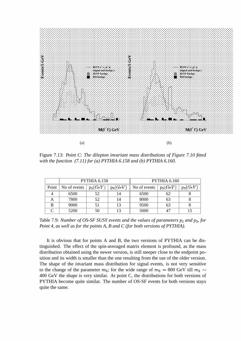
7.5. NEUTRALINO DECAY STUDIESIN MSUGRA 91
0Ö
100Ù200
300ä400å
0Ö
50Ø
100Ù
150Ù
200Ú
P1 688.4 27.75P2 49.79 0.5558P3 13.15 0.4076
M(lâ + l-) GeV
Û
Eve
nts/
5 G
eV
SUSY eÜ + e-, Ý µÞ + µÞ -
(signal and backgr.)ßSUSY backgr.ÜSM backgr.Ü
(a)
0Ö
100
200Ú300ä400
0Ö
50Ø
100Ù
150Ù
200Ú
P1 580.9 24.21P2 46.90 0.6927P3 15.48 0.5131
M(lâ + l-) GeV
ÛE
vent
s/5
GeV
SUSY eÜ + e-, Ý µÞ + µÞ -
(signal and backgr.)ßSUSY backgr.ÜSM backgr.Ü
(b)
Figure7.13: Point C: Thedileptoninvariant massdistributionsof Figure 7.10fittedwith thefunction (7.11)for (a) PYTHIA6.158and(b) PYTHIA6.160.
PYTHIA 6.158 PYTHIA 6.160
Point No of events pÆ�é�ê�ëíìïî pç é�êEëíìïî No of events pÆ%é�ê�ëíìGî pç é�ê�ëíìGî4 6500 52 14 6500 62 8A 7800 52 14 8000 63 8B 9000 51 13 9500 63 8C 5200 50 13 5000 47 15
Table7.9: Numberof OS-SFSUSYeventsandthevaluesof parameters æ Æ and æðç , forPoint 4, aswell asfor thepointsA, B andC (for bothversionsof PYTHIA).
It is obvious that for points A and B, the two versionsof PYTHIA can be dis-tinguished.The effect of the spin-averagedmatrix elementis profound,asthe massdistribution obtainedusingthenewer version,is still steepercloseto theendpointpo-sition andits width is smallerthantheoneresultingfrom theuseof theolderversion.The shapeof the invariant massdistribution for signal events, is not very sensitiveto the changeof the parameterÂÄÃ ; for the wide rangeof ÂÍÃòñ 800 GeV till ÂÄÃòó400 GeV the shapeis very similar. At point C, the distributionsfor both versionsofPYTHIA becomequitesimilar. Thenumberof OS-SFeventsfor bothversionsstaysquitethesame.

92 CHAPTER7. NEUTRALINO DECAYS IN ATLAS
A noticeabledifferencebetweenthe invariantmassspectrafor differentvaluesofÂÍÃ , is theappearanceof a peakaround90GeV(seepointsB andC).
At point B, theZ peakis mainly dueto theproductionof thesecondchargino ÐÑ ÕÆin the decay Ðô Î Ò ÐÑ ÕÆjõ with a branchingratio of 17ö . At this mSUGRApoint thesquarkshave smallermasses( ó 600GeV) thanthoseat Point4 sothe Ð÷ Ðø productiondominates.TheSUSYcross-sectionis larger(63.34pb). Moreover, thegluino decaysmainly as Ðø Ò Ðô Îfùô Å Ðùô Î ô (78ö branchingratio). Sucha decaymodeof the gluino atPoint4 is impossibledueto thefactthat Ðô Î is heavier there.
At point C, the Ð÷ Ðø productionagain dominates.The gluino doesnot have threebody decaysat this point; instead,it decaysmainly to Ð÷ ù÷ . Subsequentlythe squarksdecayproducingneutralinosandcharginos. TheZ peakat this point comesfrom thedecaysof thesecharginos. TheSUSYcrosssectionis evenlargerhere(94.3pb). Al-thoughat pointsB andC the Z peakis quite high, it still doesnot obscurethe massdistributionsfor Ê 72 GeVthatweareinterestedin.
As we move from point 4 towardspoint C, the massesof the sleptons(squarks)decreasefrom ó 800GeV( ó 900GeV)down to ó 250GeV( ó 500GeV).
Changing the úbûýüjþ and ÿ����7ü�� Ò��A supplementarystepin our studieswasto explore the potentialuseof the channelÐÑ� Ò ÐÑ� Î Ó�ÔXÓyÕ in moreregionsof the mSUGRAparameterspacewhereexcept fromthe � � and �ÏÎ Ë parameters,thevalueof úbû'üUþ andthe ÿ����7ü � Ò�� werechanged.There-foreweconsideredthreemorecaseswherefirst the ÿ����7ü�� Ò�� wastakennegative (whilethe remainingmSUGRAparameterswerethe sameasthe onesat point 4), secondlythevalueof the úbû'üUþ assumedto beequalto 2 (
Ò Ì 0) andfinally úbû'üUþ = 2 withÒ Ê
0. For thesethreecases,aswell asfor thecasewhere úbû'üUþ = 10 and ÿ����7ü � Ò�� Ì 0 (asthey arepoint 4), we first calculatedthe branchingratio of our decaychannelwhilescanningtheparameterspaceof ( � ��� � Î Ë ) (Figure7.14).
In thefollowing partof this section,studiesin a few selectedpointswith differentvaluesof mSUGRAparametersarepresented.

7.5. NEUTRALINO DECAY STUDIESIN MSUGRA 93
tanβ = 10, µ� > 0
200�
400
600�
800�
200400� 600
� 800�
0�
0.05�0.1�
0.15�0.2�
m�
1/2� GeV
m0� (G
eV)
BR
(%
)
(a)
tanβ = 10, µ� < 0
200�
400
600�
800�
200400� 600
� 800�
0�
0.025�0.05�
0.075�
0.1�
m�
1/2� GeV
m0� (G
eV)
BR
(%
)
(b)
tanβ = 2, µ� > 0
200�
400
600�
800�
200� 400
600� 800
�
0�0.05
� 0.1�0.15� 0.2�
m� 1/2� GeV
m0� (G
eV)
BR
(%
)
(c)
tanβ� = 2, µ� < 0
200�
400
600�
800�
200� 400
600� 800
�
0�0.05
� 0.1�0.15� 0.2�
m� 1/2� GeV
m0� (G
eV)
BR
(%
)
(d)
Figure7.14: Branching ratios of the decay ÐÑ � Ò Ñ � Î Ó Ô Ó Õ in different regionsof themSUBRAparameterspace, (a) úbû'üUþ = 10 and ÿ����7ü���� � Ì 0, (b) úbû'üUþ = 10 andÿ����7ü���� � Ê 0, (c) úbû'üUþ = 2 and ÿ����7ü���� � Ì 0, (d) úbû'üUþ = 2 and ÿ����7ü���� � Ê 0.

94 CHAPTER7. NEUTRALINO DECAYS IN ATLAS
The dileptonmassdistribution of opposite-signsame-flavour leptonpairsfor thepoint
� � ñ 800GeV � Î Ë ñ 200GeV � � ñ 0 úbû'üUþ¹ñ 10 � Ê 0
calledfor simplicity in thisanalysis,point ‘minus’, is shown in Figure7.15.Thesamedistribution but fitted with thefunction(7.11)is presentedin Figure7.16.It shouldbepointedout thatthis pointdiffersfrom this of point4 only by the ÿ����7ü ��� � .
Thenumberof OS-SFSUSYeventsexpectedareabout6700for bothversionsofPYTHIA andfor an integratedluminosity of 3 à 10á pbÕ Î . The alreadywell knowneffect of thespin-averagedmatrix elementis again visible in theseFigures.Themassdistribution in Figure7.15bis very similar to theoneof point 4, aseven thepositionof the endpointdoesnot change.At point ‘minus’, the massdifferencebetweenthenext-to lightestandthe lightestneutralinois still � 72 GeV. TheSUSYcrosssectionfor thispoint is quitethesamewith theoneat point4 ( ó 32pb).
0Ö
200Ú
400
600×
0Ö
50Ø
100Ù
150Ù
200Ú
M(lâ + l-) GeV
Û
Eve
nts/
5 G
eV
SUSY eÜ + e-, Ý µÞ + µÞ -
(signal and backgr.)ßSUSY backgr.ÜSM backgr.ÜSUSY eÜ + µÞ -, eÝ - µÞ +
(a)
0Ö
250
500Ø750
1000Ù
0Ö
50Ø
100Ù
150Ù
200Ú
M(lâ + l-) GeV
Û
Eve
nts/
5 G
eV
SUSY eÜ + e-, Ý µÞ + µÞ -
(signal and backgr.)ßSUSY backgr.ÜSM backgr.ÜSUSY eÜ + µÞ -, eÝ - µÞ +
(b)
Figure7.15:Point ‘minus’: Dileptoninvariantmassdistributionsfor SUSYeventscon-taining OS-SFleptonpairs (full histogram),OS-OFleptonpairs (dashedhistogram),and for tt eventscontainingOS-SFpairs (dashedblack histogram), for an integratedluminosityof 3 à 10á pbÕ Î , for (a) PYTHIA 6.158and (b) PYTHIA 6.160. In bothFiguresagain, theSUSYbackgroundconsistingof opposite-signsame-flavourleptonpairs is indicated(dashedgrey histogram)

7.5. NEUTRALINO DECAY STUDIESIN MSUGRA 95
0Ö
200Ú
400
600×
0Ö
50Ø
100Ù
150Ù
200Ú
P1 1191. 29.10P2 52.78 0.3970P3 15.68 0.2868
M(lâ + l-) GeV
Û
Eve
nts/
5 G
eV
SUSY eÜ + e-, Ý µÞ + µÞ -
(signal and backgr.)ßSUSY backgr.ÜSM backgr.Ü
(a)
0Ö
250
500Ø750
1000Ù
0Ö
50Ø
100Ù
150Ù
200Ú
P1 1913. 54.06P2 66.58 0.2511P3 9.370 0.2478
M(lâ + l-) GeV
ÛE
vent
s/5
GeV
SUSY eÜ + e-, Ý µÞ + µÞ -
(signal and backgr.)ßSUSY backgr.ÜSM backgr.Ü
(b)
Figure7.16: Point ‘minus’:Thedilepton invariant massdistributionsof Figure 7.15fittedwith thefunction (7.11)for (a) PYTHIA6.158and(b) PYTHIA6.160.
Anotherpoint similar to thatof point 4 but differing only in the úbû'üUþ valueis thefollowing:
� � ñ 800GeV � Î Ë ñ 200GeV � � ñ 0 úbû'üUþ¹ñ 2 � Ì 0
At thispointthoughthebranchingratiofor thedecay ÐÑ� Ò ÐÑ� Î Ó ÔWÓyÕ is negligible (ascanbeseenalsoin Figure7.14c).Thereforenodileptonmassdistributionof OS-SFleptonpairscontaininga sufficientnumberof puresignaleventscouldbereconstructed.
Trying to explore morethe parameterspacewith this topology, we changedalsothe valueof the � � parameter. Thereforethe modifiedpoint wherewe could finallyreconstructtheinvariantmassspectrumof therelevantleptonpairsis:
� � ñ 300GeV �ÏÎ Ë ñ 200GeV � � ñ 0 úbû'üUþ¹ñ 2 � Ì 0
The resultsareshown in Figures7.17 and 7.18 andthey arequite similar for bothversionsof PYTHIA. Thenumberof expectedOS-SFSUSYeventsis ó 15000(inte-gratedluminosityof 3 à 10á pbÕ Î ). TheSUSYcrosssectionis aboutthreetimeslargerthanthe oneat point 4 ( ó 104 pb), Ð÷ Ðø productiondominates,while the massof thesleptonsis about300GeV.

96 CHAPTER7. NEUTRALINO DECAYS IN ATLAS
0Ö
500Ø
1000Ù
0Ö
50Ø
100Ù
150Ù
200Ú
M(lâ + l-) GeV
Û
Eve
nts/
5 G
eV
SUSY eÜ + e-, Ý µÞ + µÞ -
(signal and backgr.)ßSUSY backgr.ÜSM backgr.ÜSUSY eÜ + µÞ -, eÝ - µÞ +
(a)
0Ö
500Ø
1000
1500
0Ö
50Ø
100Ù
150Ù
200Ú
M(lâ + l-) GeV
ÛE
vent
s/5
GeV
SUSY eÜ + e-, Ý µÞ + µÞ -
(signal and backgr.)ßSUSY backgr.ÜSM backgr.ÜSUSY eÜ + µÞ -, eÝ - µÞ +
(b)
Figure7.17: Point with úbû'üUþ ñ 2, � � ñ 300 GeV, � Ì 0: Dilepton invariant massdistributionsfor SUSYeventscontainingOS-SFleptonpairs (full histogram),OS-OFlepton pairs (dashedhistogram), and for tt eventscontainingOS-SFpairs (dashedblack histogram),for (a) PYTHIA6.158and(b) PYTHIA6.160.
0Ö
500Ø
1000
0Ö
50Ø
100 150 200
P1 1977. 45.67P2 48.95 0.3458P3 13.84 0.2543
M(lâ + l-) GeV
Û
Eve
nts/
5 G
eV
SUSY eÜ + e-, Ý µÞ + µÞ -
(signal and backgr.)ßSUSY backgr.ÜSM backgr.Ü
(a)
0Ö
500Ø
1000
1500
0Ö
50Ø
100 150 200
P1 2434. 52.41P2 51.45 0.2835P3 12.87 0.2209
M(lâ + l-) GeV
Û
Eve
nts/
5 G
eV
SUSY eÜ + e-, Ý µÞ + µÞ -
(signal and backgr.)ßSUSY backgr.ÜSM backgr.Ü
(b)
Figure7.18:Point with úbûýüjþ ñ 2, � � ñ 300GeV, � Ì 0:Thedileptoninvariant massdistributionsof Figure 7.17fittedwith the function (7.11)for (a) PYTHIA6.158and(b) PYTHIA6.160.

7.6. SUMMARY 97
Finally the ÿ����7ü���� � waschangedto negative while úbû'üUþ ñ 2. As demonstratedinFigure7.14d,at thepoint
� � ñ 800GeV �ÏÎ Ë ñ 200GeV � � ñ 0 úbû'üUþ¹ñ 2 �.Ê 0
our decaychannelhasvanishingbranchingratio,evenfor smallervaluesof � � .
7.6 Summary
A very motivatedextensionof the StandardModel(SM) is Supersymmetry(SUSY).A gravity-mediatedmodelof SUSY breakingis the Minimal Supergravity model(mSUGRA).In themSUGRAapproach,theMSSM-124parameterfreedomis sharplyreducedto 23: 18 of themaretheSM parametersandthe remainingfive arethe fol-lowing: � � , � Î Ë , � � , úbû'üUþ and ÿ����7ü���� � .
TheLHC Committeeselectedin 1996fivemSUGRApointsfor detailedstudies.Asixth pointwith large úbû'üjþ valuewasaddedlaterby ATLAS.
At point 4 of the mSUGRAparameterspace,the next-to lightestneutralino( ÐÑ � )hasthreebody decay( ÐÑ� Ò ÐÑ� Î Ó Ô�Ó6Õ ). This decay, givesan interestingsignatureforpoint 4, which shouldallow not only the observation of a SUSY signal,but alsothemeasurementof someparametersof thetheorysuchasthemassdifferencebetweenthesecondlightestandthelightestneutralino.Sincethesleptonsareheavy at thispointofmSUGRA,thedecayof the ÐÑ� occursthroughavirtualZ with abranchingratioof 5ö .
For ourstudies,SUSYsignaleventsfor point4 weregeneratedusingtwo versionsof theMonteCarlogeneratorPYTHIA (namelyPYTHIA 6.158and6.160). Thesu-persymmetricextensionof PYTHIA (SPYTHIA) thatcansimulateparticleproductionanddecayin mSUGRA(approximately),is implementedalreadyin the above men-tionedversionsof PYTHIA. In version6.158,the decaysof thesparticlesarepurelyphasespacetreated,while in theversion6.160thespin-averagedmatrixelementis in-cludedin thesedecays,thustakinginto accountthespinof theneutralinos,aswell asthepropagator(Z*). SubsequentlytheseproducedeventspassedthroughthestandardfastdetectorsimulationandphysicsanalysisprogramATLFAST.
Theinvariantmassof opposite-signsame-flavour leptonpairswasreconstructedatpoint 4. Theseeventsarerequiredto fulfill stringenttransversemissingenergy andlarge jet multiplicity selectioncriteria in orderto suppressthe SM background.Thespecificshapeof this dileptonmassdistribution canbeusedasevidencefor discoveryof SUSYthrough ÐÑ � production.A comparisonbetweentheresultsof thetwo versionsof PYTHIA not only at point 4 but alsoat otherpointsof the mSUGRAparameterspace, showedthatin generalit is possibleto distinguishbetweenaphasespacedecay

98 CHAPTER7. NEUTRALINO DECAYS IN ATLAS
anda spin-averagedmatrix elementneutralinodecay. Thechannel ÐÑ � Ò ÐÑ � Î�Ó Ô Ó Õ canbesuccessfullyusedfor SUSYstudiesin largeregionsof theparameterspace.

Chapter 8
Summary
In orderto obtaintherequiredmomentumresolution( !ïæ#"%$�æ#"&� 1 ' 10Õ á 'Kæ($ GeVfor æ#" Ì 300 GeV), the ATLAS Muon Spectrometershouldfulfill stringentrequire-ments. One of the most crucial mechanicalrequirementsis the fact that the MDTchambersmustbeconstructedwith 20 � m mechanicalaccuracy (r.m.sof the relativedistancebetweenthewiresof thedrift tubes).This demandingprecisionis anessen-tial ingredientof theMDT conceptandneedsto becontinuouslyconfirmedduringtheproductionphaseaftereachchamberassembly.
Wehavedevelopedawire calibrationmethodfor theATLAS MDT chambers,thatneedsno externalreferencesystem.Themainprincipalof this methodis basedon thefactthatwhena tubewire is displaced,thedistributionof theresidualsversusthedriftdistancefor trackswhich traversethe tuberight from its wire is not symmetricwiththeonefor trackswhich traversethe tubeleft from its wire. For thedeterminationoftherelativewire positions,thepositionsof two tubes(oneoneachmultilayer)arekeptfixed, while the y coordinates(perpendicularto the tracks’ direction) of the twelvesurroundingtubesaremovedtill thedistributionsof their residualsleft andright fromtheirwiresbecomesymmetric.
This methodwasappliedfor thefirst time (1998)on a groupof 14 tubes( called‘a flower pair’) of oneof thefirst full scaleprototypesof MDT chambers.Theproto-typewasconstructedatMPI, Munichandtestedat ahighenergeticmuontestbeamatCERNwhile it wasfilled with theformerATLAS baselinegas )+*,$.- $0/21 á (91/4/5).Therelative wire positions(in thedirectionperpendicularto themuontracks)for thetubesof this flower pair, werefound usingour calibrationmethod.The resultswerecomparedwith thosegiven by the X-ray tomograph(a very precisedevice placedatCERN, dedicatedto scan10ö of the MDT chambers)revealingan accuracy of ourmethodbetterthan10 � m. The successof thesestudieswasrepeatedthe followingyearby finding the wire positionsof fifty-one tubesof the sameprototypechamber;this time thechamberwasfilled with thenew baselinegas )+*,$0/43 (93/7).
99

100 CHAPTER8. SUMMARY
Simulationstudiesof the applicationof the calibrationmethodalong the wholewidth of a chamberwereperformed. For a simulatedchamberfilled with )5*6$0/73 (93/7) andhaving wire displacementsof 20 � m rms in the y direction,muontracksperpendicularto the chamberusinga GEANT basedsimulationprogramwerepro-duced.Theenergy of themuonsproducedwas180GeV. It shouldbementionedthatthechamberconsistsof 70 overlappingflower pairs. By using25000tracksperpair,theaccuracy of themethodin measuringwire displacementsin they directionwithineachflower pair (local accuracy) is 5 � m. This precisionis by a factortwo betterthantheonewe obtainedusingthetestbeamdata.Thereasonis that the ú � parameterwaskeptequalto zeroin thesimulation. This parameterexpressestheTDC responsefora null drift pathfor eachtube. It is different for eachchannelandis determinedbythedelaysof thesignalcablesandthefront-endelectronics.By introducingGaussiandistributed ú � offsetsof anrmsof 200and300psto thedrift time spectraof thetubes,thelocaluncertaintyincreasesto 8 and9 � m respectively.
By combiningtheinformationof the70flowerpairsweacquiredtheabsolutewirepositionswithin thewholechamberwith respectto thefirst centralwireswithin eachmultilayer. Theseabsolutewire positionsthatwe obtainedin thecasewherethedrifttime spectrahadGaussiandistributed ú � offsetsof an rms of 200 ps, weremeasuredwith anaccuracy of 20 � m (globalaccuracy). Assumingthoughrandomanduncorre-latedwire displacements,to get theabsolutewire positionswith respectto thewholechamber, only asmallsurroundingof eachwire is needed.Thereforeby slightly mod-ifying thecombinationprocedureof all the70flowerstheglobalaccuracy improvesto10 � m ( 89��ú � � ñ;:=<0< ps).
In orderto make full useof the potentialof this wire calibrationmethod,a totalnumberof morethan10000tracksper flower pair shouldbe used. This conclusionderivedfrom thestatisticalstudiesof themethod.
The wire calibrationmethodcan be usedsuccessfullyin determiningwire dis-placementsof chambersplacedin muontestbeamswherethemuonshave anenergyof 180GeVor more. The methoddiscussed,canprovide a very accuratetestof themechanicalaccuracy of MDT chambers,beingableat the sametime to identify andcorrectthepositionsof wiresthathave largedisplacements.
Anotherapplicationof themethodwill beits usein thedataanalysisof theATLAScosmicray set-upsthathave beenpreparedfor thecommissioningandcalibrationofthechamberproductionat differentATLAS productionsites.Finally, this calibrationmethodcouldoffer apossibilityfor onlinecalibrationof thewire positionsof theMDTchambersin thefinal set-upof theATLAS detector.
The Supersymmetry(SUSY) discovery potentialof the ATLAS detectorthroughtheproductionof thenext-to lightestneutralino( ÐÑ� ) wasalsostudied.Within theMin-
101
imal Supergravity model (mSUGRA)of SUSY, five parametersareusedin order todeterminethemassesandthecouplingsof theparticles: � � thecommonscalarmass,�ÏÎ Ë the commongauginosand Higgsinosmass, � � the trilinear Higgs-sfermion-sfermioncouplings,úbû'üUþ the ratio of the two Higgs vacuumexpectationvaluesandÿ����7ü���� � thesignof theHiggsinomassparameter. At oneof thesix pointsof mSUGRAselectedby the LHC Committeeand the ATLAS Collaborationfor detailedstudies,namelypoint4 characterizedby
� � ñ 800GeV �ÏÎ Ë ñ 200GeV � � = 0 úbû'üUþ¹ñ 10 � Ì 0 ,
the ÐÑ � hasa threebody decay( ÐÑ � Ò ÐÑ � Î�Ó Ô Ó Õ ) througha virtual Z with a branchingratioof 5ö .
This decayandits potentialSUSY andSM backgroundswerestudied. Two ver-sionsof theMonteCarlogeneratorPYTHIA wereused:PYTHIA 6.158andPYTHIA6.160. In both of these,the supersymmetricextensionof PYTHIA (SPYTHIA) thatcanperformsimulationsin mSUGRAis implemented.Themaindifferencebetweenthe two versionsis that althoughin 6.158the decaysof sparticlesarepurely phasespacetreated,in 6.160thespin-averagedmatrix elementis includedin thesedecays,thustakinginto accountthespinof theneutralinos,aswell asthepropagator(Z ).
Thegeneratedeventswerepassedthroughthestandardfastsimulationof theAT-LAS Collaboration,ATLFAST. For anintegratedluminosityof 3 à 10á pbÕ Î , werecon-structedtheinvariantmassof opposite-signsame-flavour(OS-SF)leptonpairsatpoint4, aswell asat threeotherpointsof the( � ��� � Î Ë ) space(wherethemassdifferencebetweenthetwo lightestneutralinosis thesameasat point4, >@?BADCEGF0EIH ñ;>KJL�MN9O >KJL�M PRQ72 GeV). The sameprocedurewasfollowed for a few morepointsof the mSUGRAparameterspacewherewe changedalso the úbû'üjþ and the ÿ����7ü���� � . After applyingstringentselectioncriteria in thedistributionsobtainedandcomparingthem,we con-cludedthat in generalit is possibleto distinguishbetweena phasespacedecayanda spin-averagedmatrix elementneutralinodecay. The channel ÐÑ � Ò ÐÑ � Î#Ó Ô Ó Õ canbesuccessfullyusedfor SUSYstudiesin largeregionsof theparameterspace.


Bibliography
[ALE99a] M. Aleksa: Performanceof the ATLASMuon Spectrometer, PhD Thesis,CERN,1999.
[ALE99b] M. Aleksa: Rate Effects in High-ResolutionDrift Chambers, CERN-EP/99-101,1999,NIM A 446/3(2000),pp.435-443.
[ALI95] ALICE Collaboration: ALICE Technical Proposal, CERN/LHCC/95-71,1995.
[AMA91] U. Amaldi, W. deBoerandH. Furstenau:Phys.Lett. B260(1991)447.
[ATL94] ATLAS Collaboration: ATLASTechnical Proposal,CERN/LHCC/94-43,1994.
[ATL97] ATLAS Muon Collaboration: ATLAS Technical Design Report,CERN/LHCC/97-22,1997.
[ATLb97] ATLAS Collaboration: Barrel Toroid Technical Design Report,CERN/LHCC/97-19,1997.
[ATLc97] ATLAS Collaboration: Central Solenoid Technical Design Report,CERN/LHCC/97-21,1997.
[ATLcl96] ATLAS Collaboration: CalorimeterPerformanceTechnical DesignRe-port, CERN/LHCC/96-40,1996.
[ATLe97] ATLAS Collaboration: End-Cap Toroids Technical Design Report,CERN/LHCC/97-20,1997.
[ATLi97a] ATLAS Collaboration:InnerDetectorTechnicalDesignReport,Volume1CERN/LHCC/97-16,1997.
[ATLi97b] ATLAS Collaboration: Inner DetectorTechnical DesignReport,Volume2 CERN/LHCC/97-17,1997.
[ATLl96] ATLAS Collaboration:Liquid ArgonCalorimeterTechnicalDesignReport,CERN/LHCC/96-41,1996.
103

104 BIBLIOGRAPHY
[ATLm97] ATLAS Collaboration: Magnet SystemTechnical Design Report,CERN/LHCC/97-18,1997.
[ATLp98] ATLAS Collaboration: Pixel Detector Technical Design Report,CERN/LHCC/98-13,1998.
[ATLt96] ATLAS Collaboration: Tile Calorimeter Technical Design Report,CERN/LHCC/96-42,1996.
[ATL98] E. Richter-Waset.al.: ATLFAST2.0: a fastsimulationpackage for ATLAS,AtlasNoteATL-PHYS-98-131,CERN,1998.
[ATL99] ATLAS Collaboration:ATLASDetectorandPhysicsPerformanceTechnicalDesignReport,CERN/LHCC/99-15,1999.
[BAE95] H.Baeret.al.: Phys.Rev. D52 (1995)2746.
[BAR94] S. Baranov et al.: GammaSensitivityof PressurizedDrift Tubes,ATLASNoteATL-MUON-94-036,CERN,1994.
[BAT98] R. Battiston: The Alpha Magnetic Spectrometer (AMS): searchfor antimatter and dark matter on the International Space Station,Nucl.Phys.Proc.Suppl.65:19-26,1998.
[BER98] J.Berbiersetal.: Nucl. Instrum.MethodsA419 (1998)342-350.
[BLU94] W. Blum, L. Rolandi: Particle Detectionwith Drift Chambers, SpringerVerlag,1993.
[BNL73] CommonbasepreamplifierIO354-2ansshapingamplifier IO532-01,In-strumentationDivision,BrookhavenNationalLaboratory, Upton(NY),1973.
[BOS98] V. Bartheldet al.: Constructionof theFull-ScalePrototypeof a BOSMDTchamber, ATLAS NoteATL-MUON-98-256,CERN,1998.
[CHE93] A. Cheplakov et al.: MuonRatesin ATLAS,ATLAS NoteATL-MUON-93-21,CERN,1993.
[CHL93] G.A. Chelkov et al.: Investigationof spectral efficiencyof pressurizeddrifttubesfor detectionof neutronsin the energy range between5 eV and 200 keV,ATLAS NoteATL-MUON-93-31,CERN,1993.
[CHO98] S.Chouridouetal.: ProtvinoDrift Tubesfor BML-98.TestResults,ATLASNoteATL-MUON-98-247,CERN,1998.
[CHO00] S.Chouridouetal.: ConstructionandTestof MDT Chambersfor theATLASMuon Spectrometer, Nucl. Instrum.MethodsA461 (2001)17-20,ATLAS NoteATL-COM-MUON-2000-008,CERN,2000.
BIBLIOGRAPHY 105
[CMS94] CMSCollaboration:CMSTechnical Proposal,CERN/LHCC/94-38,1994.
[COL67] S.ColemanandJ.Mandula:Phys.Rev. 159(1967)1251.
[CRE97] P. Creti et al.: Testbeamresultsfrom the CalypsoMDT chamber, ATLASNoteATL-MUON-97-196,CERN,1997.
[DEI98] M.Deile et al.: MDT Track Fitting with the MaximumLikelihoodMethod,ATLAS MUON-98-240,CERN,1998.
[DEI99] M.Deile et al.: ODYSSEUS:a SiliconTelescopefor TestBeamExperiments,ATLAS COM-MUON-99-015,CERN,1999.
[DEI00] M.Deile: Optimizationandcalibration of the Drift-TubeChambers for theATLASMuonSpectrometer, PhDthesis,Munich,2000.
[DEN90] D. Denegri: Standard ModelPhysicsat theLHC (ppCollisions),publishedin [JAR90], Vol.I, 56-117,1990.
[DRA97] D. Drakoulakos et al.: TheHigh-PrecisionX-RayTomograph for qualitycontrol of theATLASMDT MuonSpectrometer, CERN-OPEN-97-023,1997.
[ELL83] J.Ellis, D.V. NanopoulosandK. Tamvakis: Phys.Lett. B121(1983)123.
[ELL91] J.Ellis, S.Kelley andD. V. Nanopoulos:Phys.Lett. B260(1991)131.
[FAB97] F. Gianotti: PrecisionSUSYmeasurementswith ATLAS:SUGRA‘Point 4’,ATLAS NoteATL-PHYS-97-110,CERN,1997.
[GEA93] GEANT, CERNProgramLibrary LongWriteup,W5013,1993.
[GSC00] E. Gschwendtner:BenchmarkingtheParticle Backgroundin theLHC Ex-periments,PhDthesis,CERN,2000.
[HES98] N.P. Hessey: ThePrecisionDrift Chambers for theATLASMuonSpectrom-eter, Nucl. Instrum.MethodsA419 (1998)326-330.
[IBA82] L. Ibanez:Phys.Lett.B118(1982)73.
[INO82] K. Inoueet.al.: Prog.Theor. Phys.68 (1982)927.
[JAR90] G.JarlskogandD. Rein(editors):Proceedingsof theLargeHadronColliderWorkshop,CERN/90-10,1990.
[KEK] KEK, NationalLaboratoryfor High Energy Physics,Japan
[KOR98] O. Kortner:PrivateCommunication.
106 BIBLIOGRAPHY
[KOR00] O. Kortner: MTGEANT-3, the previousversion of MTGEANT-4- TheMu-nich Test-StandSimulationProgramme, ATLAS Note ATL-MUON-2000-021,CERN,2000.
[KRO00] H. Krohaet al.: Analysisof the X-RayTomographData of theBOSMDTprototypeChamber, ATLAS NoteATL-MUON-2000-015,CERN,2000.
[LAN81] P. Langacker: Phys.Rep.72 (1981)185.
[LEP99] ALEPH 99-007CONF-99-003,DELPHI 99-8 CONF-208,L3 Notes2382and2383,OPAL PN382.
[LEP01] TheLEP HiggsWorking Group: ALEPH 2001-66,DELPHI 2001-113,L3Note2699,OPAL PN479,LHWG Note/2001-03.
[LHCb98] LHCB Collaboration: LHCb Technical Proposal, CERN/LHCC/98-4,1998.
[MRE01] S.Mrenna: Privatecommunication.
[OHM94] P. Ohmann,V. BargerandM.S.Berger: Phys.Rev. D49 (1994)4908.
[PDG00] D.E. Groometal.: Particle DataGroup,Eur. Phys.J.C15 (2000)1.
[PRI88] J.R.Primacketal.: Ann.Rev.Nucl.Part.Sci.38 (1988)751.
[RAU01] F. Rauscher: Test von Driftkammernmit kosmischen Myonen: Bau dererstenAusbaustufedesTeleskopsundUntersuchungseinerLeistungsfaehigkeit,Diplomathesis,Munich,2001.
[RIE97a] W. Riegler: MDT Efficiency, DoubleTrack Separation,ATLAS MUON-97-173,CERN,1997.
[RIE97] W. Riegler: Limits to Drift ChamberResolution,PhDthesis,CERN,1997.
[RIE99] W. Riegler et al.: ResolutionLimits of Drift Tubes,CERN-EP/99-99,1999,NIM A 443/1(2000),pp.156-163.
[SAU77] F. Sauli: Principlesof operation of mutliwire proportionalanddrift cham-bers,CERN77-09,1977.
[SM61] S.Glashow: Nucl.Phys.22 (1961)579;S.Weinberg: Phys.Rev.Lett.19 (1967)1264;H.D. Politzer:Phys.Rev.Lett.30 (1973)1346.
[SMI97] I. Smirnov: HEED, program to computeenergy loss of fast particles ingases,Version1.01,CERN,1997.

BIBLIOGRAPHY 107
[SPE98] M. Spegel: On the Lifetimeof Proportional Counters, PhD thesis,CERN,1998.
[SPY96] S. Mrenna: SPYTHIA:A SupersymmetricExtensionof PYTHIA5.7,ANL-HEP-PR-96-63,1996.
[SUS71] P. Ramond:Phys.Rev. D3 (1971)2415;J.WessandB. Zumino: Nucl. Phys.B78 (1974)39;H. P. Nilles: Phys.Rep.110(1984)1;H.E.HaberandG.L. Kane:Phys.Rep.117(1985)75.
[VEN95] S.Venezianoet al.: Nucl. Instrum.MethodsA367 (1995)418-421.
[VIE96] G. Viehhauser: DetectorPhysicsof the ATLASprecisionmuonchambers,Ph.Dthesis,TechnicalUniversityof Vienna,1996.


Acknowledgements
First of all I would like to thankProf. DorotheeSchailefor hercontinuousguidanceandsupportfor my work. I canstill feel the joy I experiencedthe momentshein-formed me that shewill supportmy applicationfor a Marie Curie fellowship. Herdeterminationandstrengthhavealwaysbeenaninspirationto me. I thankheralsoforthewonderfulraftingexcursionssheorganizedfor ourgroup!
I am very gratefulto Prof. Chris Fabjan,maybethe first personwho encouragedmesomuchto follow a careerin particlephysics. I thankhim for having alwaysthetime to listen to my usualreportfor my work every time I wasat CERNanddiscusswith me my results.His preciousadviceguidedme many timesandhe alwaysgavemethefeelingthatworking for particlephysicsis oneof themostbeautifulthingsintheworld.
I would alsolike to thankmy teacheranda very goodfriend; Stefan Schael.Henotonly taughtmemostof thethingsI know in programminganddataanalysisbut hewasalwaysthereto encouragemeandhelpmeto find solutionsin theproblemsof mywork. Workingwith him it hasalwaysbeenapleasure.
Many thanksgo to MichaelTreichelwho gave metheideato make a PhDin Mu-nichandsupportedmein difficult moments.
I amgratefulto RaimundStrohmerandThomasTrefzgerfor their wonderfuldataanalysisideas,for introducingme in the particlephysicssimulationtechniquesandfor their help in overcomingdifficultieswith my analysis.I amalsothankful to Prof.Arnold Staude,Oliver Kortner, Mario Deile, GunterDuckeckandMadjid Boutemeurfor fruitful discussionsandexchangingideas. It wasa pleasureworking with NigelHessey during the testbeamperiodsandlearningfrom him so many hardwaretech-niques. He always managedto keepme calmedeven whenour BOS chamberwas’sick’. Many thanksto AndreiOstapchukfor hishelpandthetimehesparedto discusswith memy results.
It would beanomissionif I wouldn’t thankMrs. HertaFranz,our secretary. Shewouldalwaysbethereto helpmeandevenmakeherselfmany phonecallsfor bureau-craticmatterson behalfof measmy Germanwerenever thatgood. Many thanksgoalsoto Mr. OttoSchailefor hisquickassistancein computingproblems.
I would like to thank Meta Binder with whom I sharedthe office. We becamevery goodfriendsandwe did not only spendhoursof talking aboutphysicsbut alsohadgreattime while drinking wine andforgettinga bit theevery dayproblemsof the
109

110 BIBLIOGRAPHY
work. Many thanksto Axel Leins for the ‘thousands’optionsfor Linux commandsthatheshowedme.
I would like to thankmy Austrianfriends(theAustriangangasI call them),Edda,Helmut, Petra,Christoph,Axl, WernerandMartin. Every time I wasat CERN theykeptmea greatcompany, they mademe laughandI never felt alonethere. With thelasttwo of themI hadalso’businessdiscussions’(abouttubesandwiresof course)andI amthankfulto themfor that.
I would likeat thispoint to thanksomemorefriendswhosupportedmeduringtheyearsof my thesis. They mademe believe in myself andwerealwaystherewhenIneededthem,evenif it wasfor only a glassof beer!A big Thankyou thento Andrea,Christina,Martina, Marcella,Nils, Kostas,Babis,Norman,Stavros, Christos,Sofia,Orly andDimitris.
I amgratefulto theEuropeanCommissionwhich gave methis Marie CurieGrantandI wasableto make my thesis.Many thanksto my friendsfrom the Marie CurieAssociationfor thewonderfultimewe hadduringour regularStammtisch.
I would like to thankwith all my heartmy family; my parents,my brother, mysisterandmy sister-in-law. Without theircontinuousencouragement,supportandloveI couldnever have madeit. My motherwho taughtme to have confidencein myselfspenda fortunein telephonebills andalwaysgave me courageto continuemy workin which shewasalways interested.My fatherwould love to readthis little book Iwrotebut unfortunatelyhe left recentlyfrom this world. I still remembertheendlessdiscussionsI hadwith him aboutphysics. I have to admit that I agreewith him andnot with Einstein:thereis finally a speedfasterthanthis of thelight; thespeedof themind.
Finally, I thankGodfor giving methechanceto studythemysteriesof His won-derfulworld.
Curriculum Vitae
24May 1971 Born in Serres,Greece.
09/77- 06/83 PrimarySchoolin Thessaloniki,Greece.
09/83- 06/89 High Schoolin Thessaloniki.
June1987 First Certificatein Englishof theUniversityof Cambridge.
10/90- 10/96 Studyof Physicsat theAristotleUniversityof Thessaloniki.Diplomathesison ‘ Studiesof theATLASMDTsPropertiesfor DifferentGas-mixturesandEffectof theOperatingParameterson their performance’.
June1993 Certificateof Proficiency in Englishof theUniversityof Cambridge.
06/95- 09/95 SummerStudentatCERN.
04/96- 06/96 Erasmusstudentat theUniversityof Geneva,Switzerland.Work carriedout atCERNon theprototypeof theATLASX-ray tomograph.
06/97- 12/97 Max PlanckInstitutefor Physicsin Munich,Germany.
1/98- 1/02 Doctoralthesisat theLudwig MaximiliansUniversity(LMU)in Munich,supportedby aMarie CurieFellowshipof theEuropeanCommission(contract- � ERBFMBICT 972519).
01/98- 06/98 Germancoursesin Munich.
September1999 CERNSchoolof Computingin StareJablonki,Poland.
July2000 5thWorkshopof Marie CurieFellows at theUniversityofBonn,organizedby theEuropeanCommission.
August2000 PSISummerSchoolonPhenomenologyof GaugeInteractions,in Zuoz,Switzerland.