Embed Size (px)
Citation preview
1
Canadian Wood Council G063
The Mid-Rise Wood-Frame Construction
Handbook: Overview and Structural
Design Aspects
Marjan Popovski, Ph.D., P. Eng. Principal Scientist, FPInnovations
Adjunct Professor, University of BC
October 27, 2015
Continuing Education Course and Credits
2
Credit(s) earned on completion of
this course will be reported to AIA
CES for AIA members.
Certificates of Completion for both
AIA members and non-AIA
members are available upon
request.
This course is registered with AIA
CES for continuing professional
education. As such, it does not
include content that may be
deemed or construed to be an
approval or endorsement by the
AIA of any material of construction
or any method or manner of
handling, using, distributing, or
dealing in any material or product. _______________________________________
Questions related to specific materials, methods,
and services will be addressed at the conclusion
of this presentation.
Course Description
To facilitate the design and construction of mid-rise wood-frame
buildings in Canada, FPInnovations, in collaboration with CWC,
NRC, and WoodWorks has developed the Mid-Rise Wood-Frame
Construction Handbook.
The Handbook has been prepared to assist architects, engineers,
code consultants, developers, building owners, and Authorities
Having Jurisdiction (AHJ) in understanding the design and
construction of mid-rise wood-frame buildings in Canada.
The presentation will provide overview of all chapters of the
handbook with emphasis on structural analysis and design
aspects.
3
Learning Objectives
At the end of the this course, participants will be able to:
▫ Understand the current code status of the mid-rise wood-
frame construction in Canada
▫ Get an overview of the content of the mid-rise handbook
and all chapters
▫ Get familiar with the structural analysis and design
aspects of mid-rise buildings
▫ Get familiar with the structural analysis and design
aspects of podium buildings
4
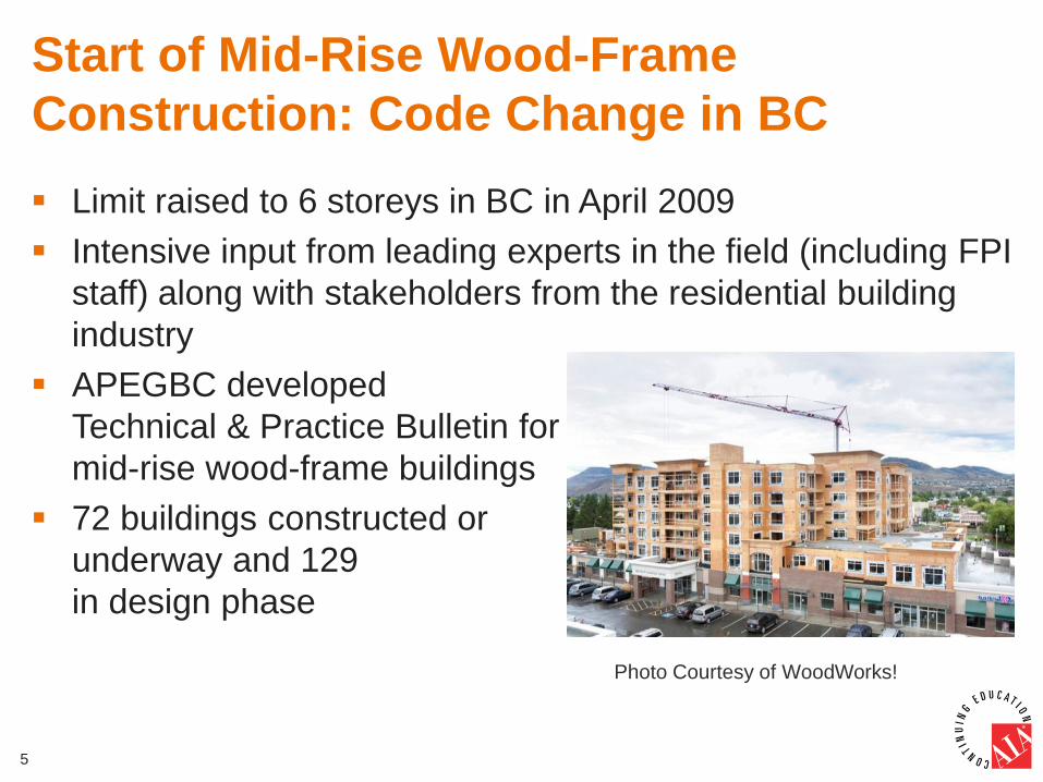
Start of Mid-Rise Wood-Frame
Construction: Code Change in BC
Limit raised to 6 storeys in BC in April 2009
Intensive input from leading experts in the field (including FPI
staff) along with stakeholders from the residential building
industry
APEGBC developed
Technical & Practice Bulletin for
mid-rise wood-frame buildings
72 buildings constructed or
underway and 129
in design phase
5
Photo Courtesy of WoodWorks!
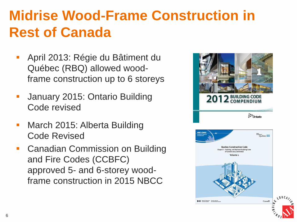
Midrise Wood-Frame Construction in
Rest of Canada
April 2013: Régie du Bâtiment du
Québec (RBQ) allowed wood-
frame construction up to 6 storeys
January 2015: Ontario Building
Code revised
March 2015: Alberta Building
Code Revised
Canadian Commission on Building
and Fire Codes (CCBFC)
approved 5- and 6-storey wood-
frame construction in 2015 NBCC
6
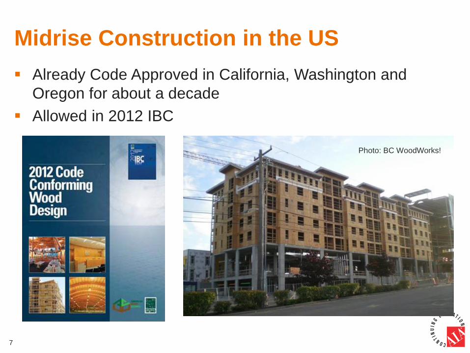
Midrise Construction in the US
Already Code Approved in California, Washington and
Oregon for about a decade
Allowed in 2012 IBC
7
Photo: BC WoodWorks!
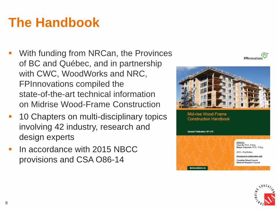
The Handbook
With funding from NRCan, the Provinces
of BC and Québec, and in partnership
with CWC, WoodWorks and NRC,
FPInnovations compiled the
state-of-the-art technical information
on Midrise Wood-Frame Construction
10 Chapters on multi-disciplinary topics
involving 42 industry, research and
design experts
In accordance with 2015 NBCC
provisions and CSA O86-14
8
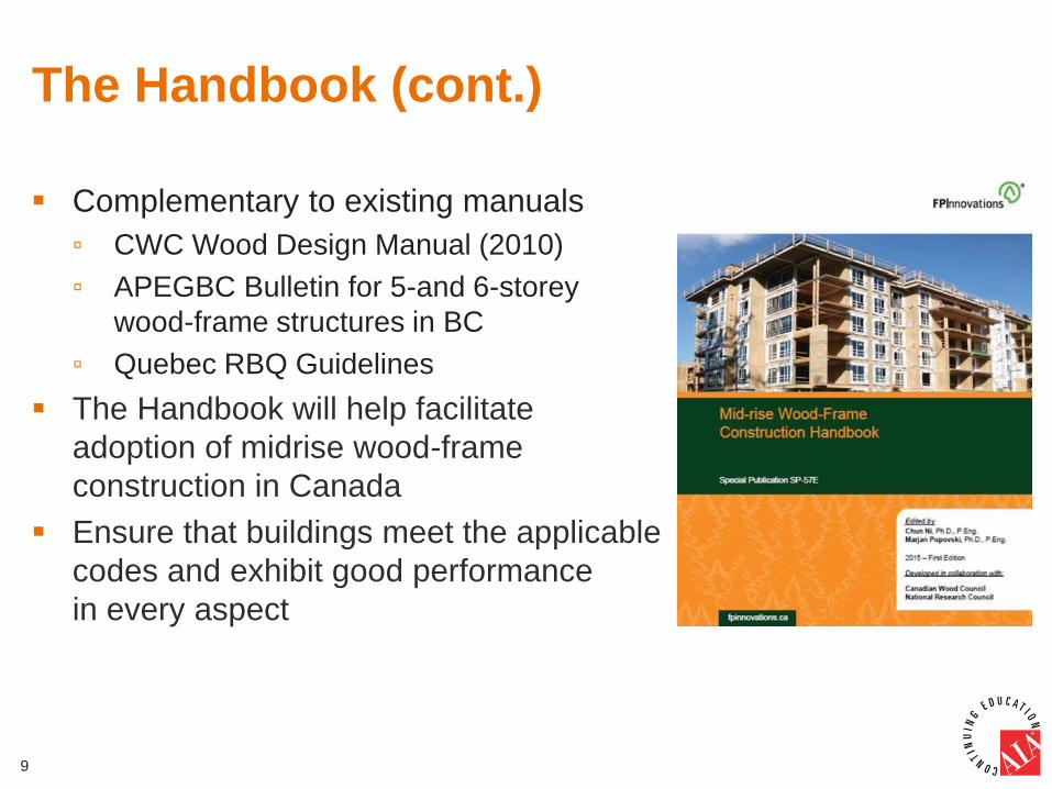
The Handbook (cont.)
Complementary to existing manuals
▫ CWC Wood Design Manual (2010)
▫ APEGBC Bulletin for 5-and 6-storey
wood-frame structures in BC
▫ Quebec RBQ Guidelines
The Handbook will help facilitate
adoption of midrise wood-frame
construction in Canada
Ensure that buildings meet the applicable
codes and exhibit good performance
in every aspect
9
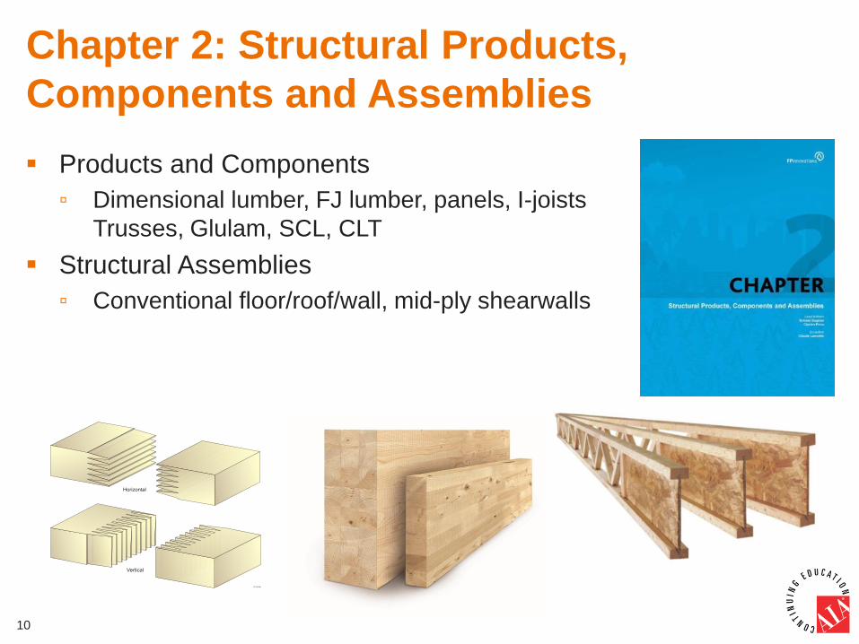
Chapter 2: Structural Products,
Components and Assemblies
Products and Components
▫ Dimensional lumber, FJ lumber, panels, I-joists
Trusses, Glulam, SCL, CLT
Structural Assemblies
▫ Conventional floor/roof/wall, mid-ply shearwalls
10
Chapter 4: Floor Vibration Control
Fundamentals of floor vibration
Review of existing design methods/gaps
A new design method for determining
vibration controlled floor span
Design examples using the method
Field control and remedies
11
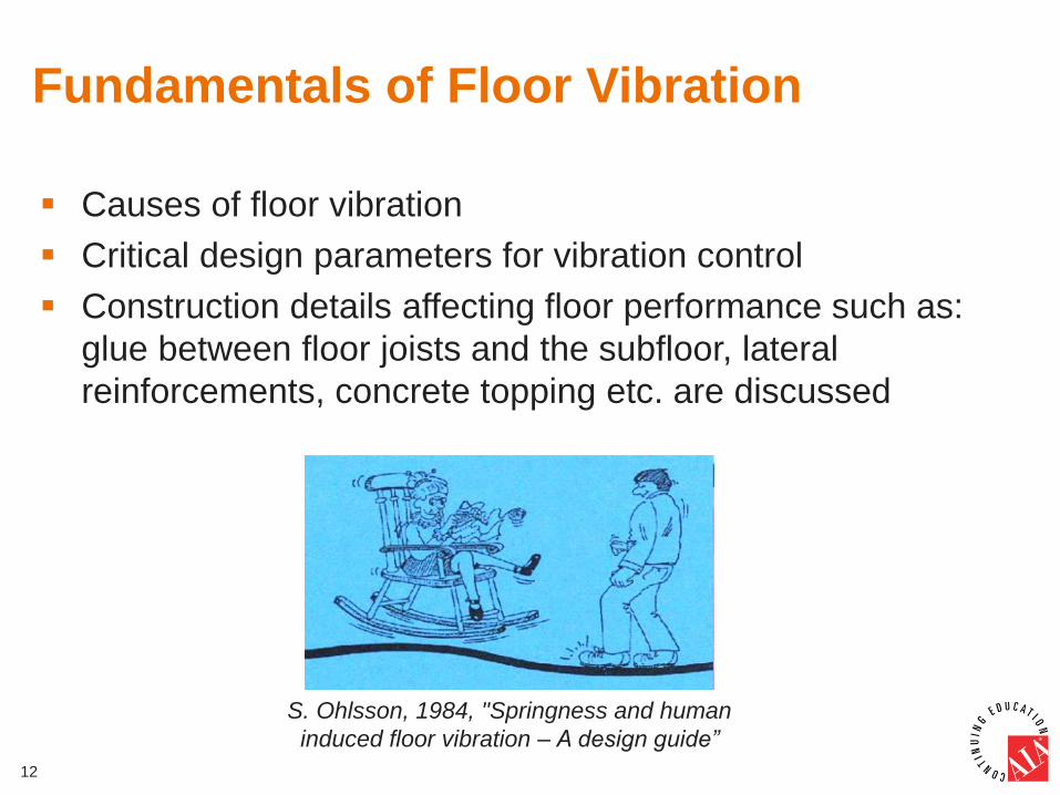
Fundamentals of Floor Vibration
Causes of floor vibration
Critical design parameters for vibration control
Construction details affecting floor performance such as:
glue between floor joists and the subfloor, lateral
reinforcements, concrete topping etc. are discussed
12
S. Ohlsson, 1984, "Springness and human
induced floor vibration – A design guide”
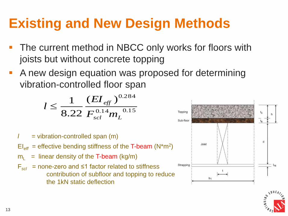
Existing and New Design Methods
The current method in NBCC only works for floors with
joists but without concrete topping
A new design equation was proposed for determining
vibration-controlled floor span
13
15.014.0
284.0)(
22.8
1
Lscl
eff
mF
EIl
l = vibration-controlled span (m)
EIeff = effective bending stiffness of the T-beam (N*m2)
mL = linear density of the T-beam (kg/m)
Fscl = none-zero and ≤1 factor related to stiffness
contribution of subfloor and topping to reduce
the 1kN static deflection
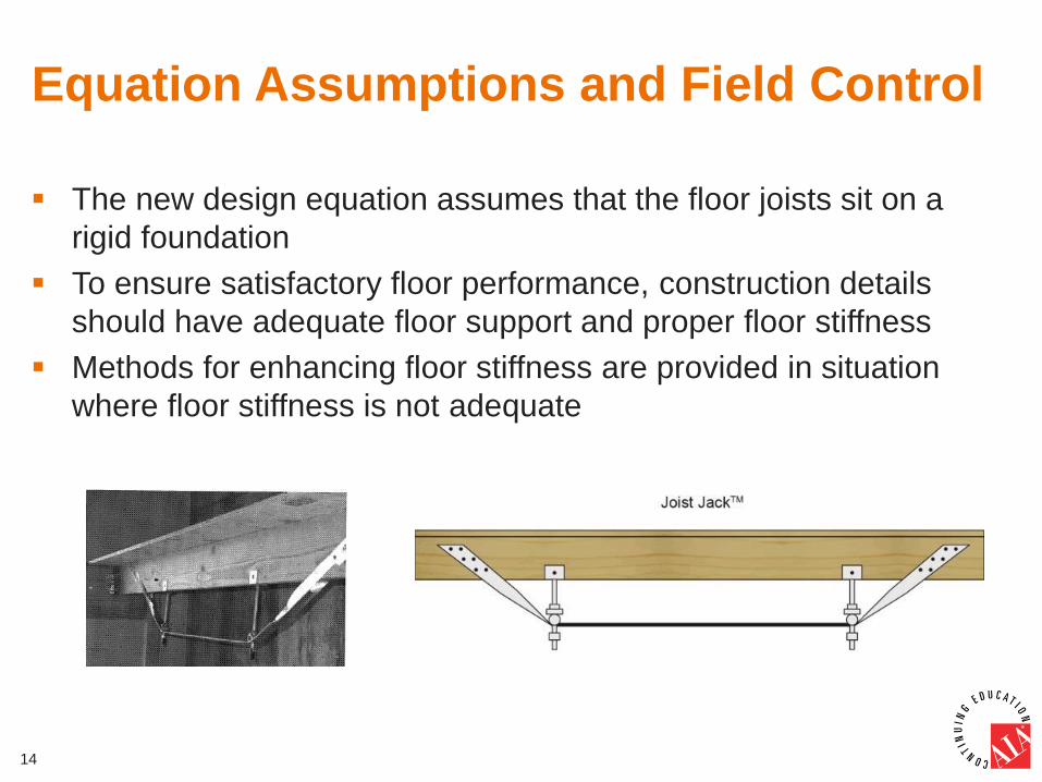
Equation Assumptions and Field Control
The new design equation assumes that the floor joists sit on a
rigid foundation
To ensure satisfactory floor performance, construction details
should have adequate floor support and proper floor stiffness
Methods for enhancing floor stiffness are provided in situation
where floor stiffness is not adequate
14
Chapter 5: Design for Vertical Differential
Movement
Vertical Differential Movement (VDM) was identified as one of the
key design issues for mid-rise wood frame construction
Content:
▫ Causes of VDM
▫ Predicting VDM
▫ Methods to reduce and accommodate VDM
▫ Recommendations for on-site moisture
management and construction sequencing
15
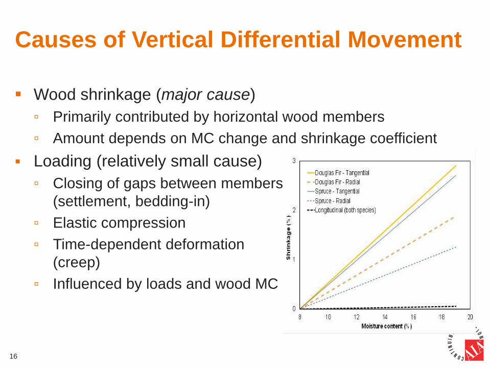
Causes of Vertical Differential Movement
Wood shrinkage (major cause)
▫ Primarily contributed by horizontal wood members
▫ Amount depends on MC change and shrinkage coefficient
Loading (relatively small cause)
▫ Closing of gaps between members
(settlement, bedding-in)
▫ Elastic compression
▫ Time-dependent deformation
(creep)
▫ Influenced by loads and wood MC
16
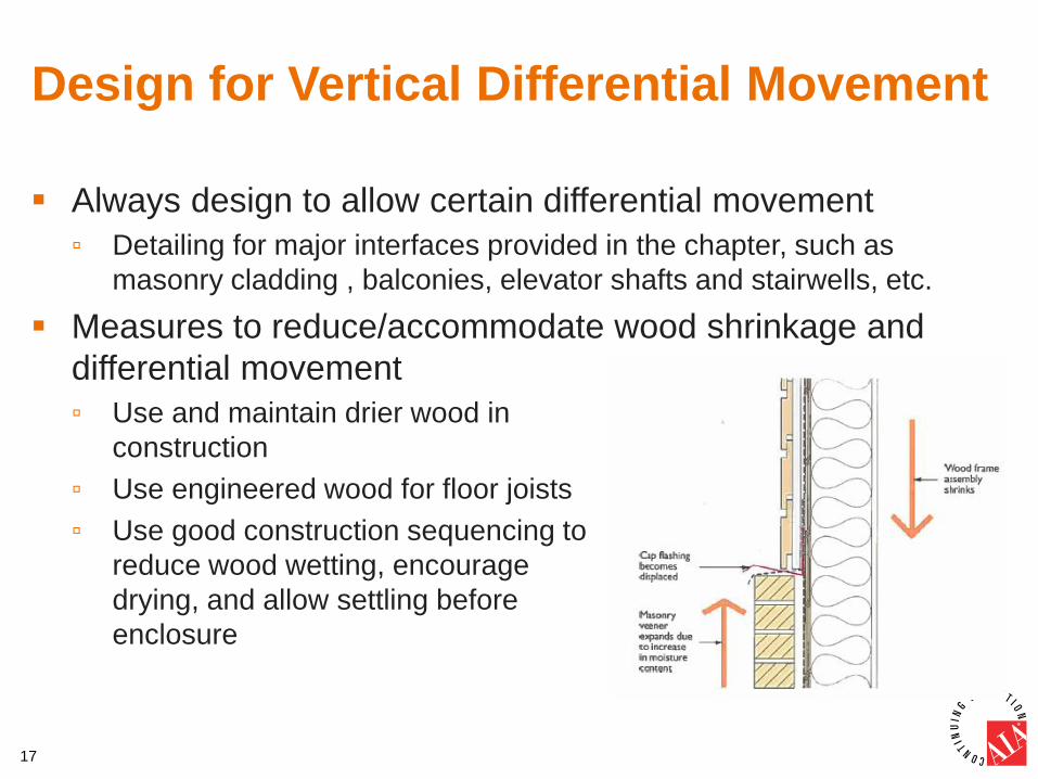
Design for Vertical Differential Movement
Always design to allow certain differential movement
▫ Detailing for major interfaces provided in the chapter, such as
masonry cladding , balconies, elevator shafts and stairwells, etc.
Measures to reduce/accommodate wood shrinkage and
differential movement
▫ Use and maintain drier wood in
construction
▫ Use engineered wood for floor joists
▫ Use good construction sequencing to
reduce wood wetting, encourage
drying, and allow settling before
enclosure
17
Chapter 6: Fire Safety Design
Fundamentals of fire safety in buildings
Fire separations and service penetrations
Fire-resistance of elements
Firewalls
Concealed spaces and fire blocks
Flame spread of interior finishes
Automatic sprinkler protection
Exterior cladding
Guidance on podium structures
Wood-based vertical shafts
Preventing fires during construction
18
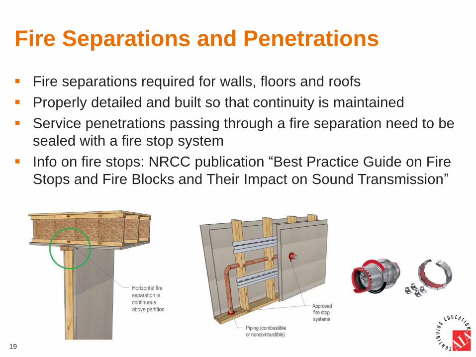
Fire Separations and Penetrations
Fire separations required for walls, floors and roofs
Properly detailed and built so that continuity is maintained
Service penetrations passing through a fire separation need to be
sealed with a fire stop system
Info on fire stops: NRCC publication “Best Practice Guide on Fire
Stops and Fire Blocks and Their Impact on Sound Transmission”
19
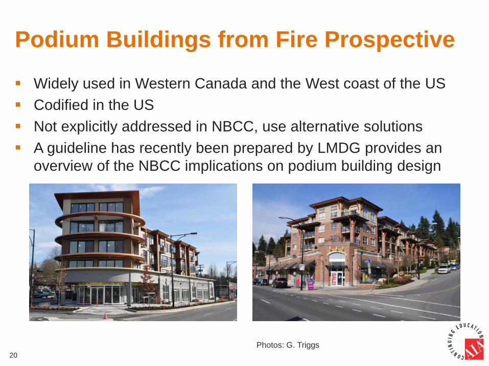
Podium Buildings from Fire Prospective
Widely used in Western Canada and the West coast of the US
Codified in the US
Not explicitly addressed in NBCC, use alternative solutions
A guideline has recently been prepared by LMDG provides an
overview of the NBCC implications on podium building design
20
Photos: G. Triggs
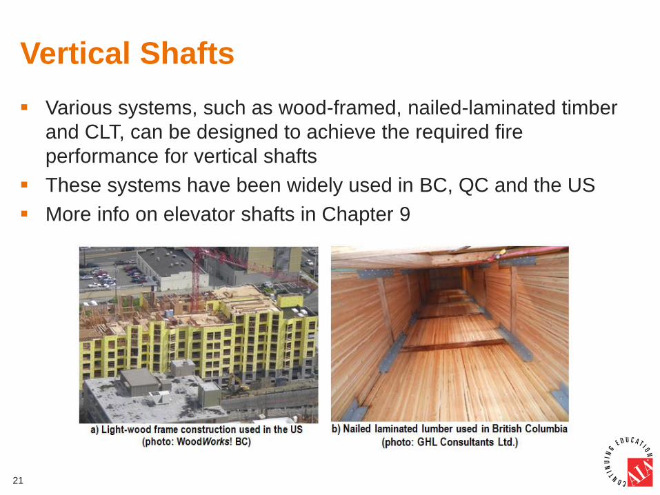
Vertical Shafts
Various systems, such as wood-framed, nailed-laminated timber
and CLT, can be designed to achieve the required fire
performance for vertical shafts
These systems have been widely used in BC, QC and the US
More info on elevator shafts in Chapter 9
21
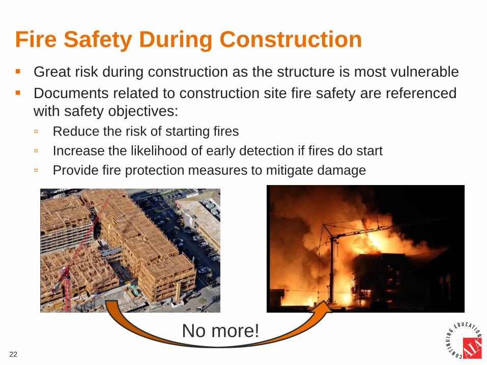
Fire Safety During Construction
Great risk during construction as the structure is most vulnerable
Documents related to construction site fire safety are referenced
with safety objectives:
▫ Reduce the risk of starting fires
▫ Increase the likelihood of early detection if fires do start
▫ Provide fire protection measures to mitigate damage
22
No more!
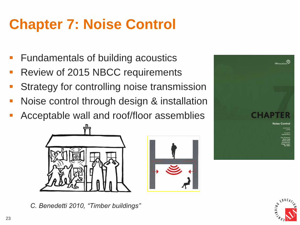
Chapter 7: Noise Control
Fundamentals of building acoustics
Review of 2015 NBCC requirements
Strategy for controlling noise transmission
Noise control through design & installation
Acceptable wall and roof/floor assemblies
23
C. Benedetti 2010, “Timber buildings”
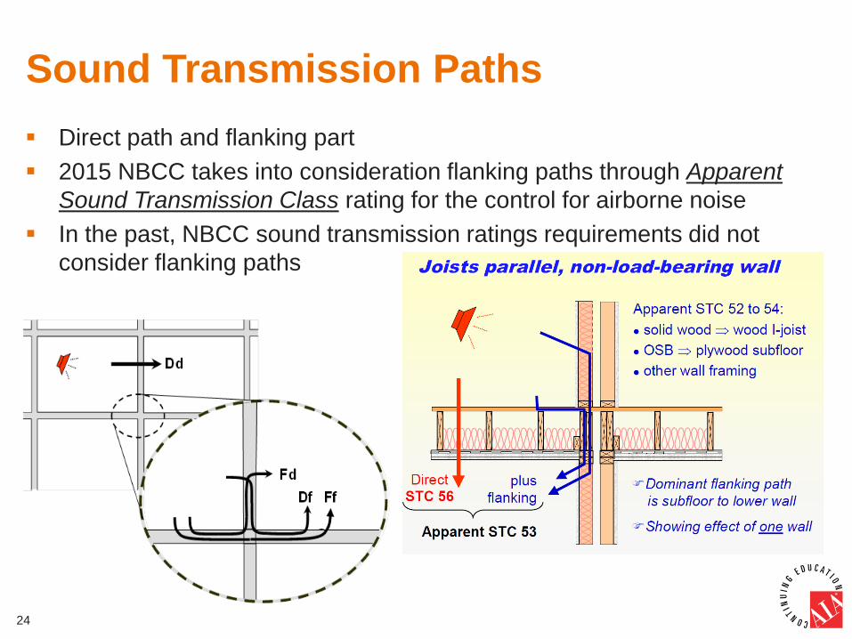
Sound Transmission Paths
Direct path and flanking part
2015 NBCC takes into consideration flanking paths through Apparent
Sound Transmission Class rating for the control for airborne noise
In the past, NBCC sound transmission ratings requirements did not
consider flanking paths
24
Three Lines of Defense Approach
An effective strategy for controlling noise
transmission in buildings:
▫ Reduce noise transmission through walls or floors
▫ Reduce noise level by reducing the vibration of walls
or floors caused by the noise source
▫ Prevent the vibration of walls or floors to be
transmitted to adjacent units
25
Noise Control by Design and Installation
Based on the Three Line Defence Approach, the
noise control through design & installation can be
achieved by:
▫ Using sound-absorbing materials with low porosity surface
to reduce airborne noise
▫ Decoupling and discontinuing of building components, if
possible
▫ Reducing impact sound transmission through wood floor
by using:
• Floating topping with weight ≥ 30kg/m2
• Resilient underlayment to reduce impact noise
26
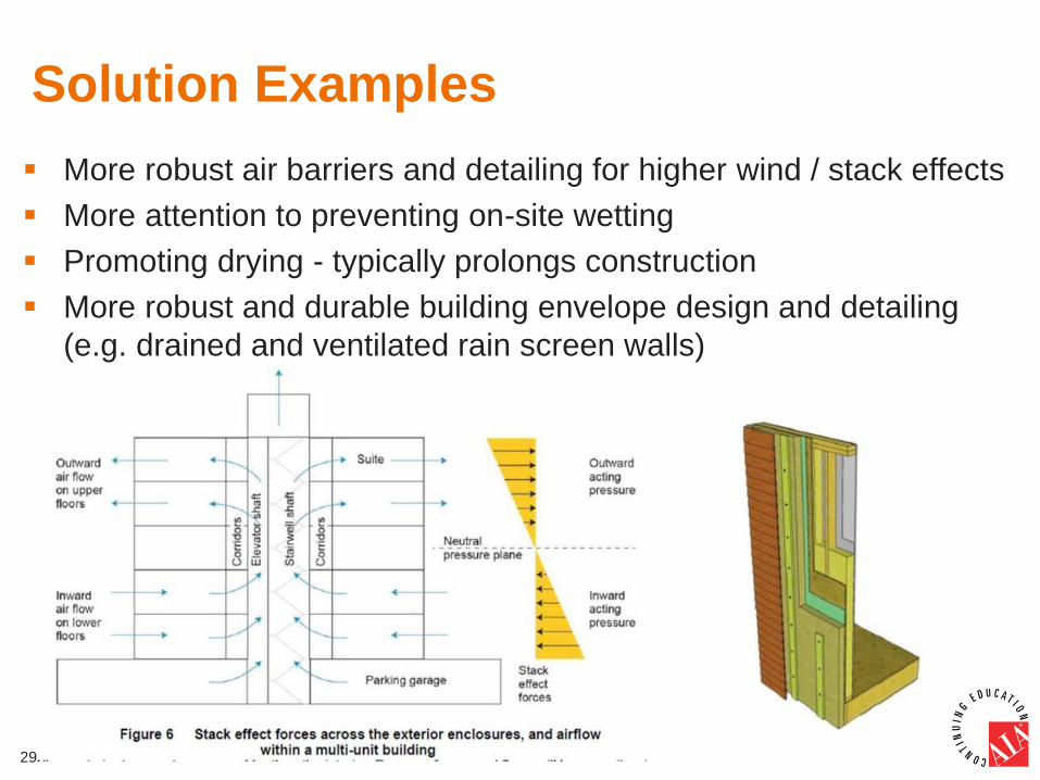
27
Chapter 8: Durable & Efficient Building
Enclosure (Building Envelope)
Increased environmental loads on the envelope
Design for higher wind and stack effect
Construction moisture management
Exterior moisture management
Thermal design
Durability and maintenance
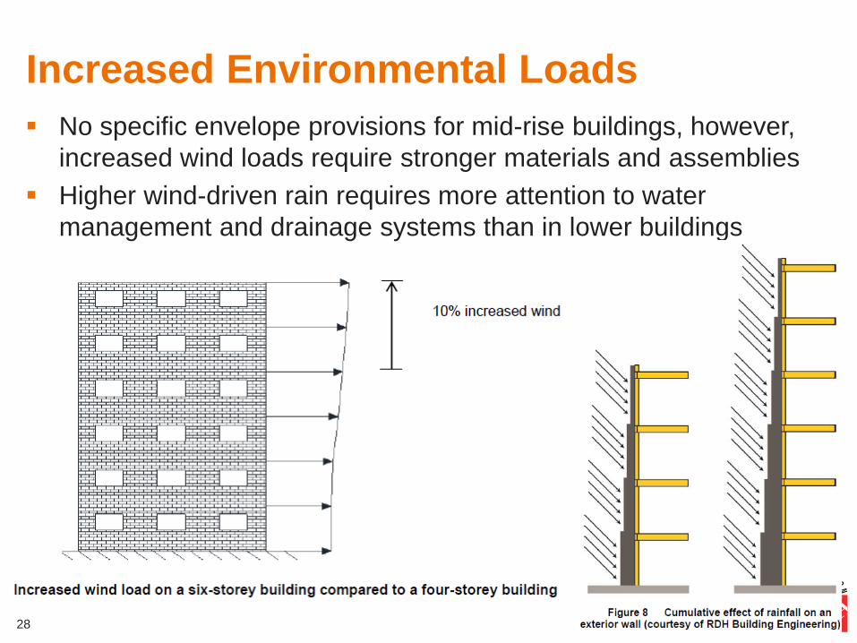
Increased Environmental Loads
No specific envelope provisions for mid-rise buildings, however,
increased wind loads require stronger materials and assemblies
Higher wind-driven rain requires more attention to water
management and drainage systems than in lower buildings
28
29
More robust air barriers and detailing for higher wind / stack effects
More attention to preventing on-site wetting
Promoting drying - typically prolongs construction
More robust and durable building envelope design and detailing
(e.g. drained and ventilated rain screen walls)
Solution Examples
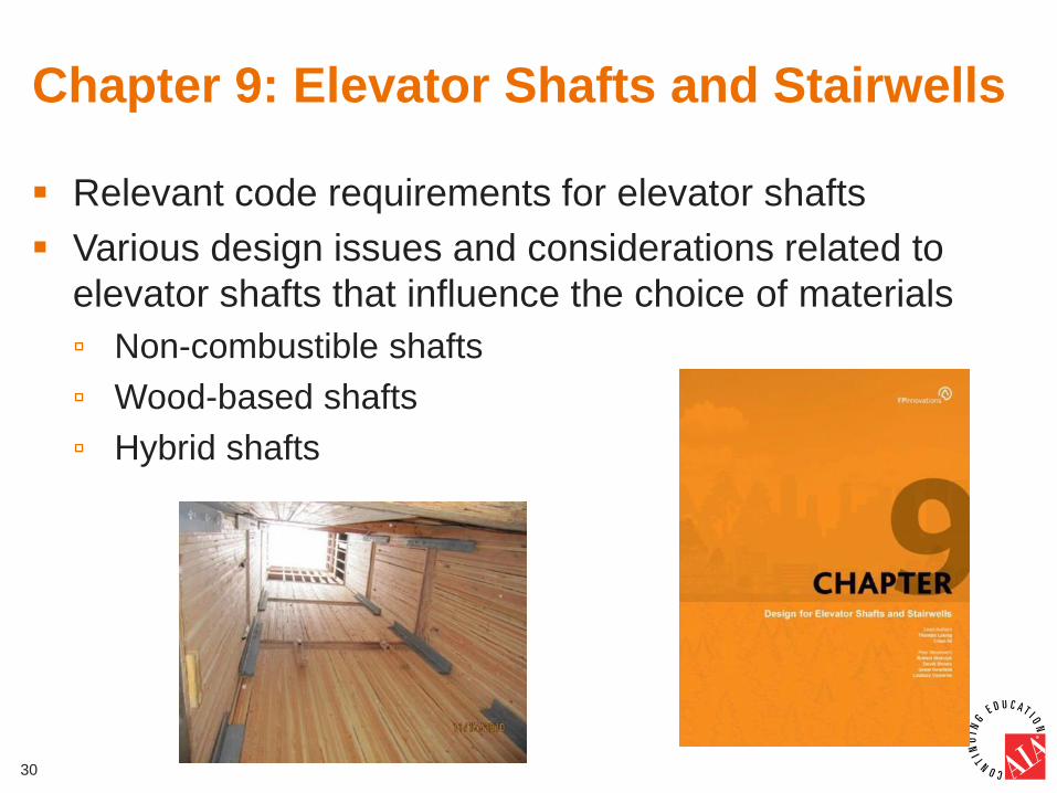
Chapter 9: Elevator Shafts and Stairwells
Relevant code requirements for elevator shafts
Various design issues and considerations related to
elevator shafts that influence the choice of materials
▫ Non-combustible shafts
▫ Wood-based shafts
▫ Hybrid shafts
30
Code Requirements in Canada
Although mid-rise buildings are permitted in BC, Ontario,
Alberta and Quebec, the requirements for elevator shafts
and stairwells are currently different
In BC building code, combustible shafts/stairwells with a
minimum of 1-hour fire-resistance rating are allowed,
(consistent with 2015 NBCC)
In Quebec only non-combustible elevator shafts and
stairwells are allowed with 1-hour rating
In Ontario non-combustible stairwells are required with
1.5-hour fire-resistance rating
31
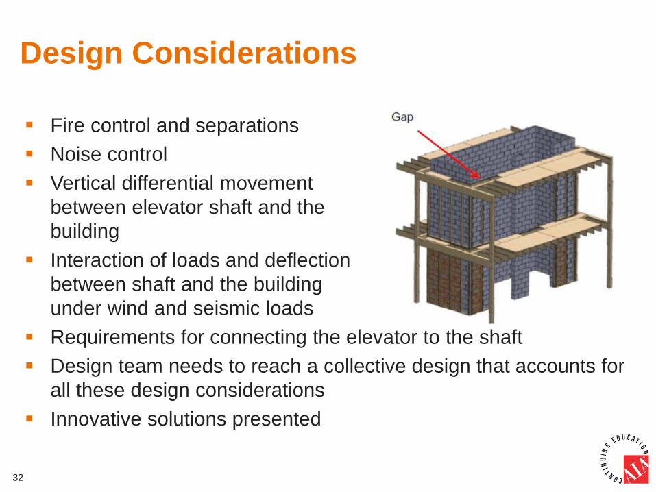
Design Considerations
Fire control and separations
Noise control
Vertical differential movement
between elevator shaft and the
building
Interaction of loads and deflection
between shaft and the building
under wind and seismic loads
Requirements for connecting the elevator to the shaft
Design team needs to reach a collective design that accounts for
all these design considerations
Innovative solutions presented
32
Chapter 10: Prefabricated Systems
Overview of various prefabricated systems and advantages
Preconstruction process
Manufacturing
Transportation
Installation and site procedures
Certification standards
33

Prefabricated Element Categories
Components
▫ Beams, Columns, Trusses, mass timber frame elements
Panelized building elements
▫ Walls, floors, ceilings, mass timber plates
Volumetric systems
▫ 3-D modules that include floor, walls and ceiling
34
Standardization in Canada
CSA A277 "Procedure for certification of prefabricated
buildings, modules and panels" (Available Fall 2015)
Procedures for certification of prefabricated buildings,
modules and panels completely revised
Applies to all forms of prefabricated systems and buildings of
all occupancies
Focus on compliance markings, such as labels, stamps and
specification sheets
35
Chapter 3: Structural Design
Code requirements
General analysis and design
Fundamental building period
Deflection of multi-storey shear walls
Linear dynamic analysis
Diaphragm flexibility
Capacity-based design
High-capacity shear walls and
diaphragms
Force transfer around openings
Design of podium structures
36
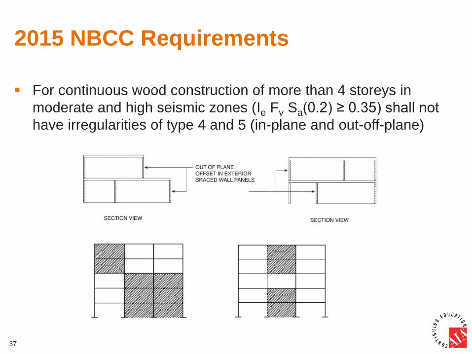
2015 NBCC Requirements
For continuous wood construction of more than 4 storeys in
moderate and high seismic zones (Ie Fv Sa(0.2) ≥ 0.35) shall not
have irregularities of type 4 and 5 (in-plane and out-off-plane)
37
2015 NBCC and 2014 CSAO86
Requirements (cont.)
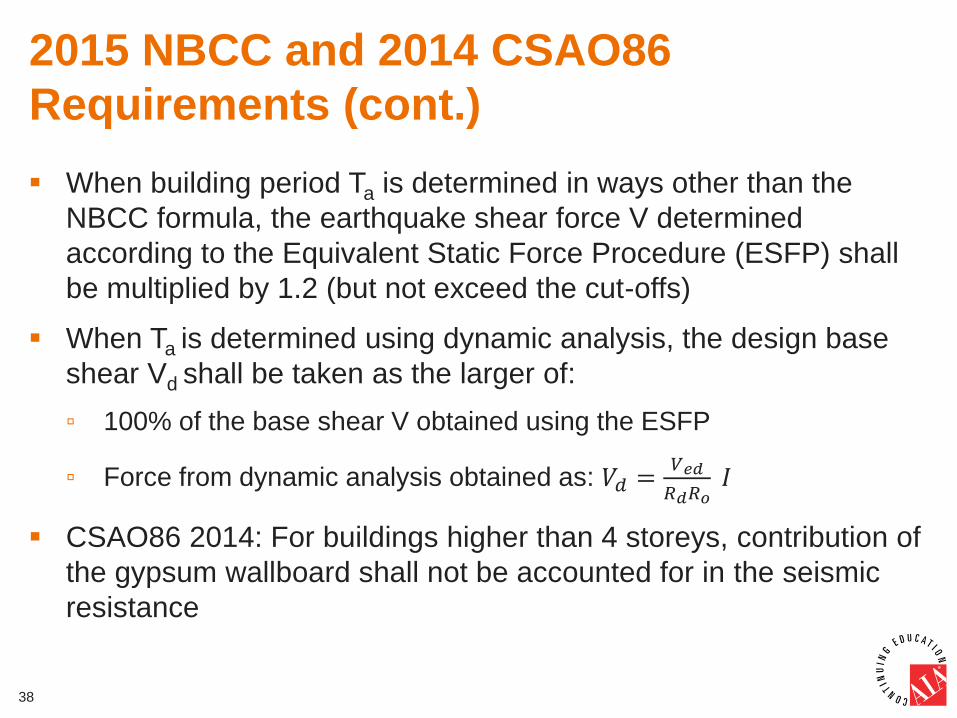
When building period Ta is determined in ways other than the
NBCC formula, the earthquake shear force V determined
according to the Equivalent Static Force Procedure (ESFP) shall
be multiplied by 1.2 (but not exceed the cut-offs)
When Ta is determined using dynamic analysis, the design base
shear Vd shall be taken as the larger of:
▫ 100% of the base shear V obtained using the ESFP
▫ Force from dynamic analysis obtained as: 𝑉𝑑 =𝑉𝑒𝑑
𝑅𝑑𝑅𝑜 𝐼
CSAO86 2014: For buildings higher than 4 storeys, contribution of
the gypsum wallboard shall not be accounted for in the seismic
resistance
38
Building Period
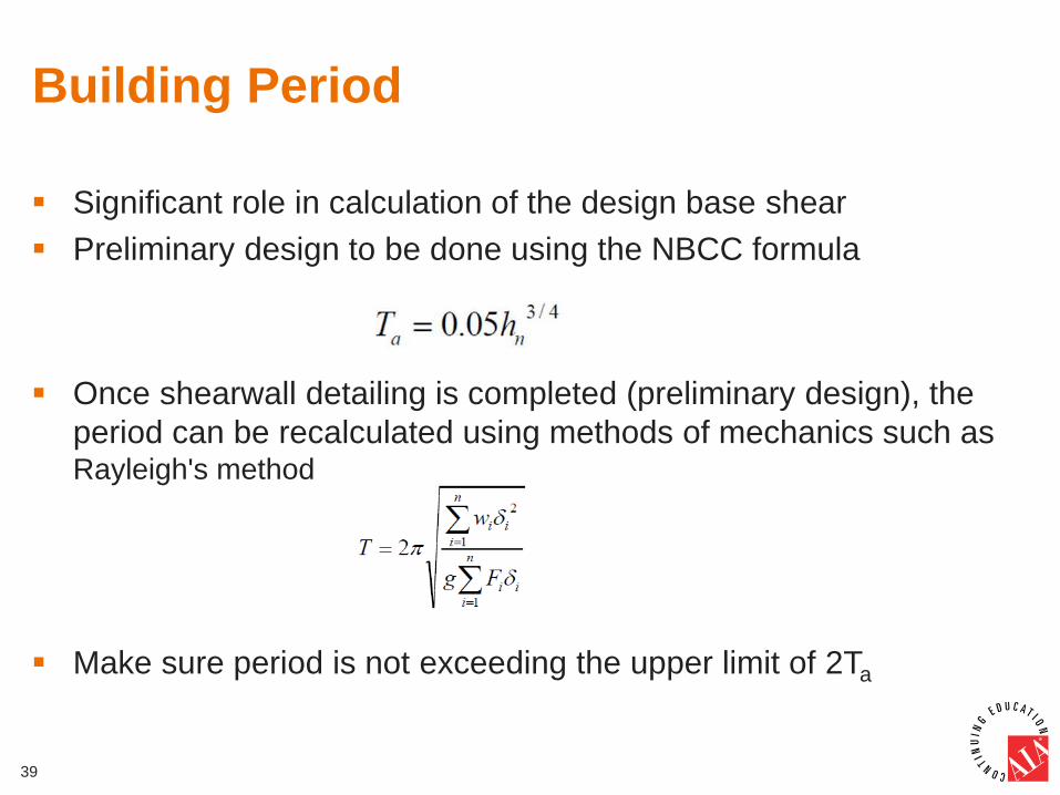
Significant role in calculation of the design base shear
Preliminary design to be done using the NBCC formula
Once shearwall detailing is completed (preliminary design), the
period can be recalculated using methods of mechanics such as Rayleigh's method
Make sure period is not exceeding the upper limit of 2Ta
39
Gypsum Wallboard and Stucco
Significant influence on the building period
Although gypsum wallboard shall not be taken in the resistance,
its stiffness and that of the stucco shall be included when
determining the building period
The initial stiffness can be calculated using the slope between the
points of 0% and 40% of capacity (ASTM E2126)
Gypsum wallboard and stucco shall not be accounted for in lateral
drift calculations (NBCC, as not part of SFRS)
40
Deflection Single Shear Wall
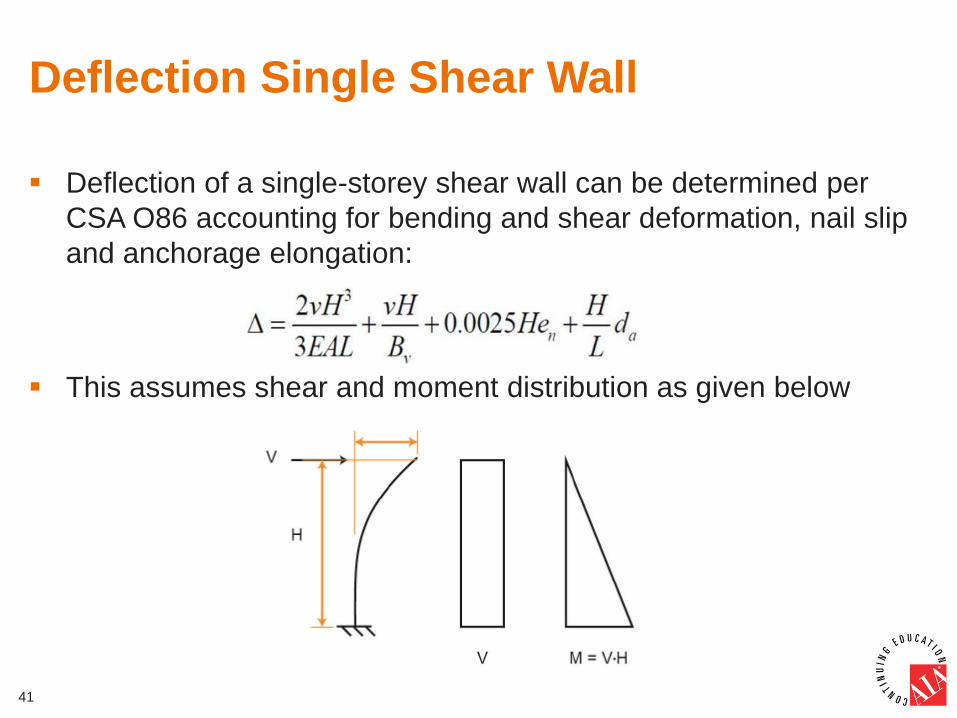
Deflection of a single-storey shear wall can be determined per
CSA O86 accounting for bending and shear deformation, nail slip
and anchorage elongation:
This assumes shear and moment distribution as given below
41
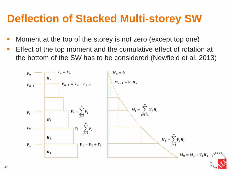
Deflection of Stacked Multi-storey SW
Moment at the top of the storey is not zero (except top one)
Effect of the top moment and the cumulative effect of rotation at
the bottom of the SW has to be considered (Newfield et al. 2013)
42
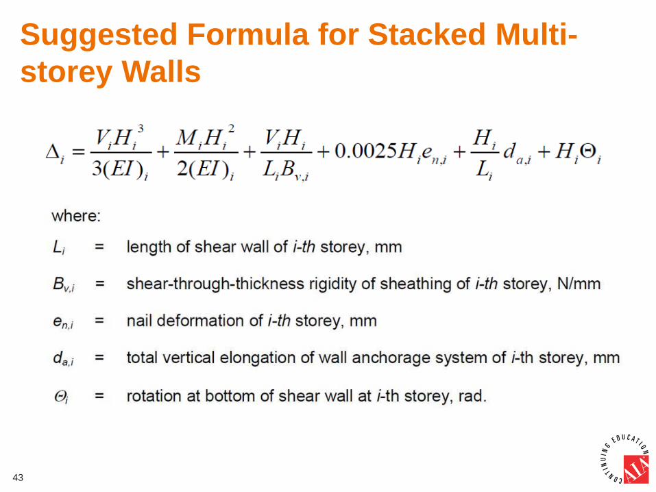
Suggested Formula for Stacked Multi-
storey Walls
43
Linear Dynamic Analysis (LDA)
Use of LDA should be encouraged in analysis and design
Benefits of LDA are:
▫ Considers the effect of higher mode participation
▫ Better determines building deflections and storey drifts
▫ Allows for three-dimensional modelling
▫ Reduces the minimum torsional effect required under the ESFP
▫ Better considers the effect of vertical changes in RdRo (podiums)
Challenge: the stiffness properties and other input parameters are
not easily determined
44
Proposed Steps of LDA
Step one (preliminary analysis): Perform an initial analysis and
design to determine the properties of each wall forming part of the
LLRS
▫ Allows designers to get the information required to determine stiffness
and deflection characteristics of the shearwalls
Step two: Use the preliminary analysis info to generate input data
for LDA for a multi-level structure
The design base shear must be the larger of the dynamic design
force Vd and the 100% of static design force V.
45
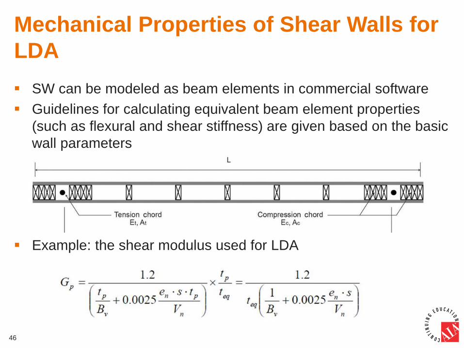
Mechanical Properties of Shear Walls for
LDA
SW can be modeled as beam elements in commercial software
Guidelines for calculating equivalent beam element properties
(such as flexural and shear stiffness) are given based on the basic
wall parameters
Example: the shear modulus used for LDA
46
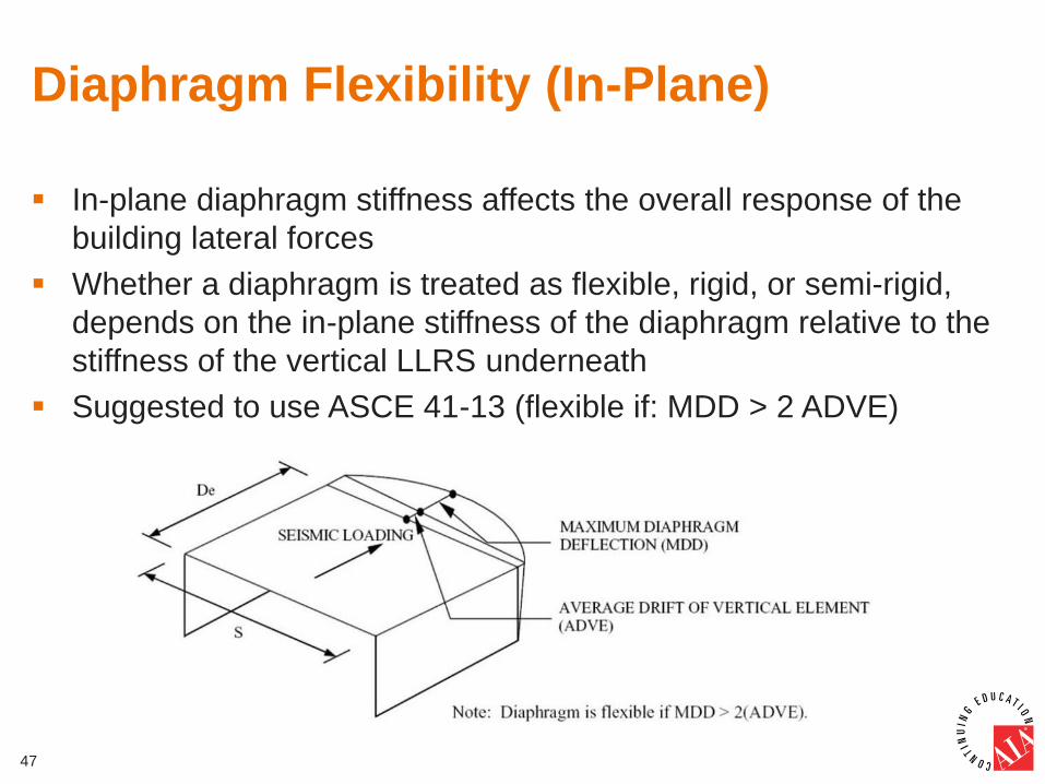
Diaphragm Flexibility (In-Plane)
In-plane diaphragm stiffness affects the overall response of the
building lateral forces
Whether a diaphragm is treated as flexible, rigid, or semi-rigid,
depends on the in-plane stiffness of the diaphragm relative to the
stiffness of the vertical LLRS underneath
Suggested to use ASCE 41-13 (flexible if: MDD > 2 ADVE)
47
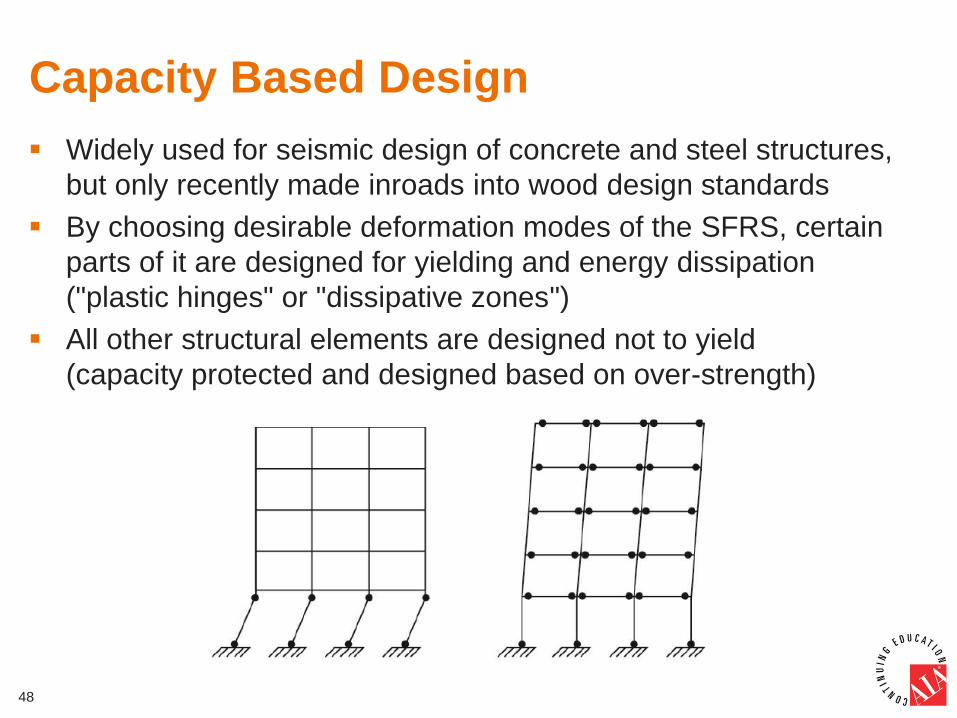
Capacity Based Design
Widely used for seismic design of concrete and steel structures,
but only recently made inroads into wood design standards
By choosing desirable deformation modes of the SFRS, certain
parts of it are designed for yielding and energy dissipation
("plastic hinges" or "dissipative zones")
All other structural elements are designed not to yield
(capacity protected and designed based on over-strength)
48
CSAO86 Provisions on Capacity Design
Increased design loads on critical system components and
force transfer elements
Anchor bolts, inter-storey connections, and hold-downs to be
designed for seismic loads that are at least 20% greater than
the force that is being transferred
Intent: To ensure that the desired ductile nail yielding is
achieved throughout the structure without any failure in the
hold-downs and shear transfer connections (Popovski et al.,
2009).
49
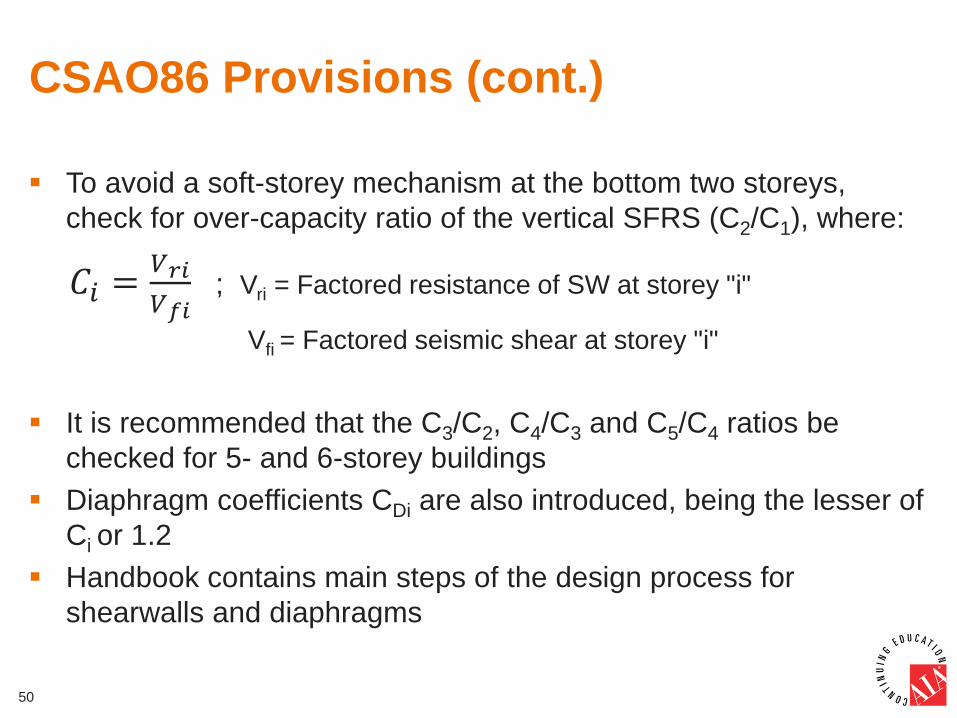
CSAO86 Provisions (cont.)
To avoid a soft-storey mechanism at the bottom two storeys,
check for over-capacity ratio of the vertical SFRS (C2/C1), where:
𝐶𝑖 =𝑉𝑟𝑖
𝑉𝑓𝑖 ; Vri = Factored resistance of SW at storey "i"
Vfi = Factored seismic shear at storey "i"
It is recommended that the C3/C2, C4/C3 and C5/C4 ratios be
checked for 5- and 6-storey buildings
Diaphragm coefficients CDi are also introduced, being the lesser of
Ci or 1.2
Handbook contains main steps of the design process for
shearwalls and diaphragms
50
High-Capacity Shear Walls and
Diaphragms
May be needed in mid-rise buildings in high seismic zones and in
commercial buildings with large openings
The Handbook introduces:
▫ Midply shearwalls
▫ Diaphragms with multiple rows of fasteners
Both to be designed using the mechanics-based approach for
shear walls and diaphragms in 2014 CSA O86
Design and detailing requirements, and factored resistances of
some configurations of Midply walls are provided
51
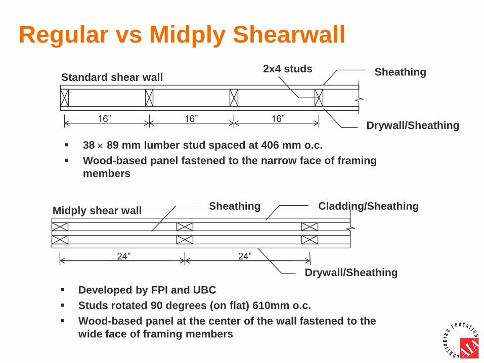
Regular vs Midply Shearwall
38 89 mm lumber stud spaced at 406 mm o.c.
Wood-based panel fastened to the narrow face of framing
members
Developed by FPI and UBC
Studs rotated 90 degrees (on flat) 610mm o.c.
Wood-based panel at the center of the wall fastened to the
wide face of framing members
Standard shear wall 2x4 studs
16” 16” 16”
Sheathing
Drywall/Sheathing
24” 24”
Midply shear wall
Drywall/Sheathing
Cladding/Sheathing Sheathing
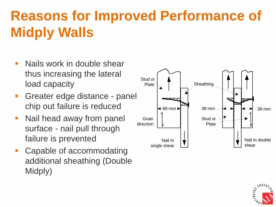
Nails work in double shear
thus increasing the lateral
load capacity
Greater edge distance - panel
chip out failure is reduced
Nail head away from panel
surface - nail pull through
failure is prevented
Capable of accommodating
additional sheathing (Double
Midply)
Reasons for Improved Performance of
Midply Walls
Nail in single shear
Nail in double shear
Sheathing Stud or
Plate
Grain direction
89 mm
Stud or Plate
38 mm 38 mm
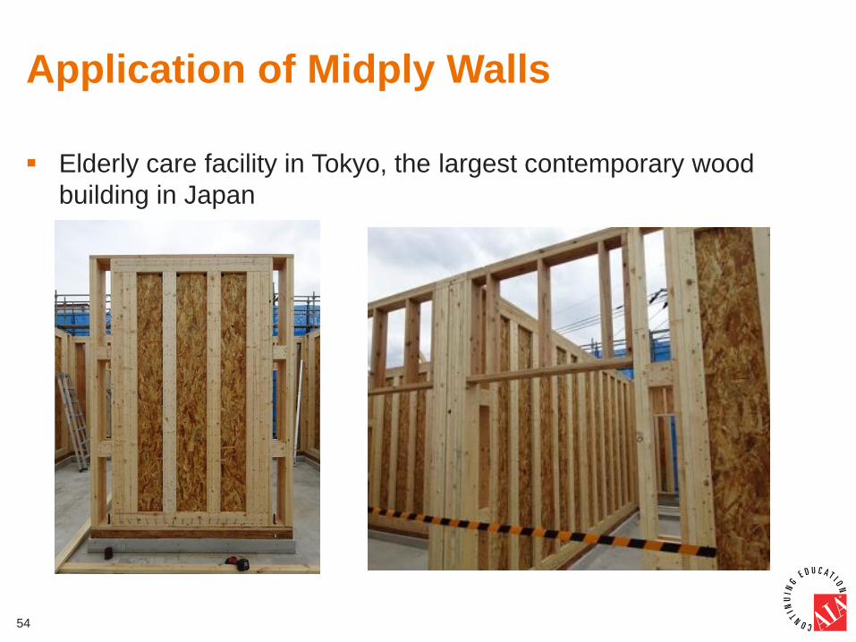
Application of Midply Walls
Elderly care facility in Tokyo, the largest contemporary wood
building in Japan
54
Force Transfers Around Openings
Most diaphragms have openings for elevator shafts, stairwells,
skylights, pipes, ducts, etc.
This induces more shear demand on the diaphragm (higher
design forces)
This "weakening effect" depends on the ratio of the opening size
vs. the area of the entire diaphragm
Solution: Design for the increased shear around the opening
Three methods available:
▫ Drug strut analogy: Consistently unconservative
▫ Cantilever beam analogy: Most conservative
▫ Vierendeel Truss analogy: Reasonable agreement with measured
forces, but cumbersome. Design example provided.
55
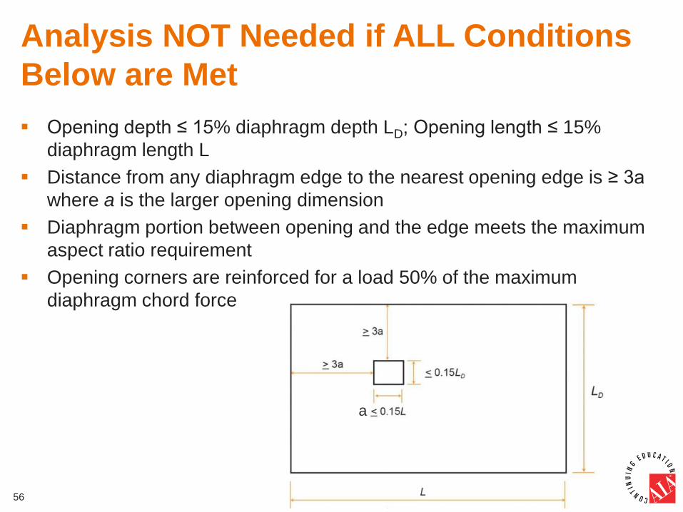
Analysis NOT Needed if ALL Conditions
Below are Met
Opening depth ≤ 15% diaphragm depth LD; Opening length ≤ 15%
diaphragm length L
Distance from any diaphragm edge to the nearest opening edge is ≥ 3a
where a is the larger opening dimension
Diaphragm portion between opening and the edge meets the maximum
aspect ratio requirement
Opening corners are reinforced for a load 50% of the maximum
diaphragm chord force
56
a
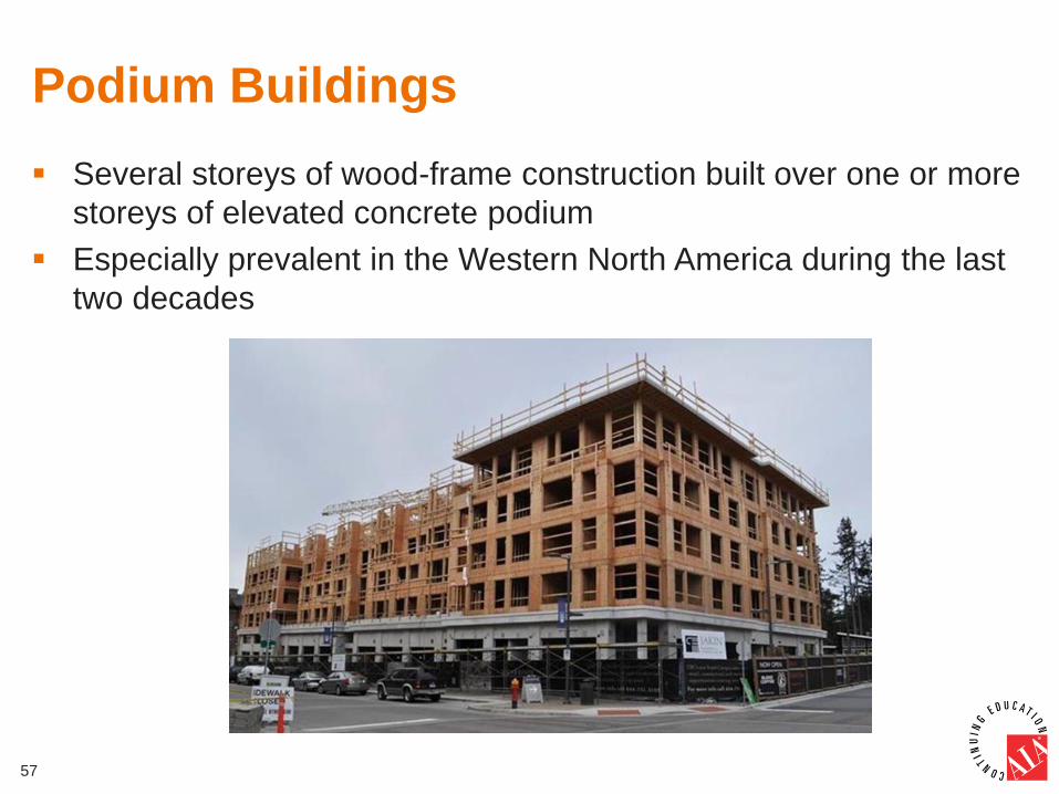
Podium Buildings
Several storeys of wood-frame construction built over one or more
storeys of elevated concrete podium
Especially prevalent in the Western North America during the last
two decades
57

Current Code Status and Approaches
Not explicitly included in 2015 NBCC and 2014 CSA O86
Designers can choose between two methods that implicitly cover
podium buildings in NBCC
First: Linear Dynamic Analysis (LDA) as default NBCC approach
▫ Analytical model should include both concrete and wood portions with
their own strength and stiffness properties
▫ Distribution of linear shear forces along the height is obtained
▫ Corresponding RdRo factors for each storey are used to determine the
design shear forces
58
NBCC Equivalent Static Procedure
Seismic interaction of concrete and wood-frame portion is ignored
Wood portion is treated as a separate building supported on the
ground designed with its own Rd Ro
Shear forces and overturning moments from the wood portion are
applied to the concrete slab below
Concrete podium designed as separate building with its own Rd
and Ro factors
No criteria in main body of NBCC when to use this approach
▫ Commentary J note 151 states that such procedure can be used
when the stiffness Kpodium > 3 Kwood
59
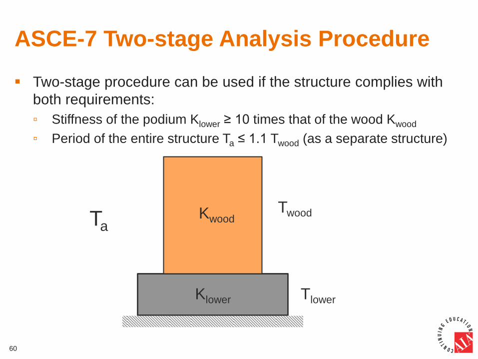
ASCE-7 Two-stage Analysis Procedure
Two-stage procedure can be used if the structure complies with
both requirements:
▫ Stiffness of the podium Klower ≥ 10 times that of the wood Kwood
▫ Period of the entire structure Ta ≤ 1.1 Twood (as a separate structure)
60
Twood Kwood
Klower Tlower
Ta
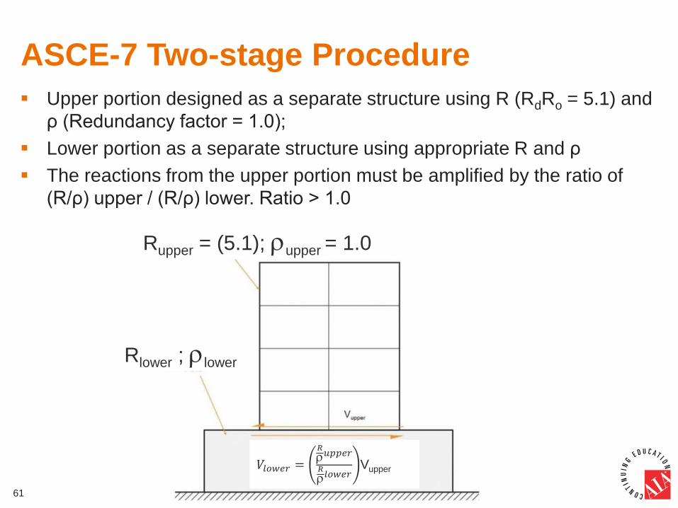
ASCE-7 Two-stage Procedure
61
Upper portion designed as a separate structure using R (RdRo = 5.1) and
ρ (Redundancy factor = 1.0);
Lower portion as a separate structure using appropriate R and ρ
The reactions from the upper portion must be amplified by the ratio of
(R/ρ) upper / (R/ρ) lower. Ratio > 1.0
Rupper = (5.1); upper = 1.0
Rlower ; lower
𝑉𝑙𝑜𝑤𝑒𝑟 =
𝑅
𝑢𝑝𝑝𝑒𝑟
𝑅
𝑙𝑜𝑤𝑒𝑟Vupper
Conclusion
62
The handbook provides guidelines for early adopters and
mainstream practitioners to design and construct mid-rise wood
frame construction in compliance with the 2015 NBCC, Provincial
Codes, and 2014 CSA O86
A total of 42 industry, research and design experts have been
involved in the development of the mid-rise handbook
The information shall be used in addition to the info already
available in CWC’s Wood Design Manual (2010), the APEGBC
Bulletin for design and construction of 5-and 6-storey wood-frame
construction, and the 2013 Quebec guidelines from Régie du
bâtiment du Québec
Thank You
This concludes The American Institute of Architects Continuing
Education Systems Course
63
Canadian Wood Council
www.cwc.ca
Wood WORKS! BC
www.wood-works.org