Embed Size (px)
Citation preview
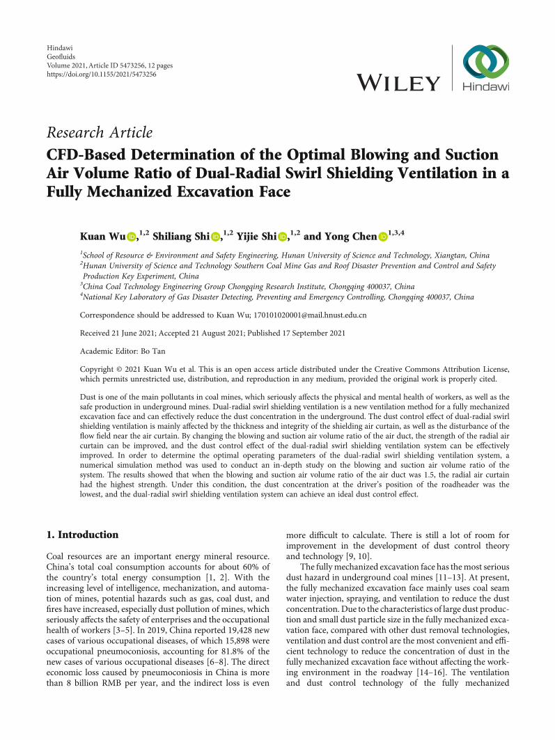
Research ArticleCFD-Based Determination of the Optimal Blowing and SuctionAir Volume Ratio of Dual-Radial Swirl Shielding Ventilation in aFully Mechanized Excavation Face
Kuan Wu ,1,2 Shiliang Shi ,1,2 Yijie Shi ,1,2 and Yong Chen 1,3,4
1School of Resource & Environment and Safety Engineering, Hunan University of Science and Technology, Xiangtan, China2Hunan University of Science and Technology Southern Coal Mine Gas and Roof Disaster Prevention and Control and SafetyProduction Key Experiment, China3China Coal Technology Engineering Group Chongqing Research Institute, Chongqing 400037, China4National Key Laboratory of Gas Disaster Detecting, Preventing and Emergency Controlling, Chongqing 400037, China
Correspondence should be addressed to Kuan Wu; [email protected]
Received 21 June 2021; Accepted 21 August 2021; Published 17 September 2021
Academic Editor: Bo Tan
Copyright © 2021 Kuan Wu et al. This is an open access article distributed under the Creative Commons Attribution License,which permits unrestricted use, distribution, and reproduction in any medium, provided the original work is properly cited.
Dust is one of the main pollutants in coal mines, which seriously affects the physical and mental health of workers, as well as thesafe production in underground mines. Dual-radial swirl shielding ventilation is a new ventilation method for a fully mechanizedexcavation face and can effectively reduce the dust concentration in the underground. The dust control effect of dual-radial swirlshielding ventilation is mainly affected by the thickness and integrity of the shielding air curtain, as well as the disturbance of theflow field near the air curtain. By changing the blowing and suction air volume ratio of the air duct, the strength of the radial aircurtain can be improved, and the dust control effect of the dual-radial swirl shielding ventilation system can be effectivelyimproved. In order to determine the optimal operating parameters of the dual-radial swirl shielding ventilation system, anumerical simulation method was used to conduct an in-depth study on the blowing and suction air volume ratio of thesystem. The results showed that when the blowing and suction air volume ratio of the air duct was 1.5, the radial air curtainhad the highest strength. Under this condition, the dust concentration at the driver’s position of the roadheader was thelowest, and the dual-radial swirl shielding ventilation system can achieve an ideal dust control effect.
1. Introduction
Coal resources are an important energy mineral resource.China’s total coal consumption accounts for about 60% ofthe country’s total energy consumption [1, 2]. With theincreasing level of intelligence, mechanization, and automa-tion of mines, potential hazards such as gas, coal dust, andfires have increased, especially dust pollution of mines, whichseriously affects the safety of enterprises and the occupationalhealth of workers [3–5]. In 2019, China reported 19,428 newcases of various occupational diseases, of which 15,898 wereoccupational pneumoconiosis, accounting for 81.8% of thenew cases of various occupational diseases [6–8]. The directeconomic loss caused by pneumoconiosis in China is morethan 8 billion RMB per year, and the indirect loss is even
more difficult to calculate. There is still a lot of room forimprovement in the development of dust control theoryand technology [9, 10].
The fullymechanized excavation face has themost seriousdust hazard in underground coal mines [11–13]. At present,the fully mechanized excavation face mainly uses coal seamwater injection, spraying, and ventilation to reduce the dustconcentration. Due to the characteristics of large dust produc-tion and small dust particle size in the fully mechanized exca-vation face, compared with other dust removal technologies,ventilation and dust control are the most convenient and effi-cient technology to reduce the concentration of dust in thefully mechanized excavation face without affecting the work-ing environment in the roadway [14–16]. The ventilationand dust control technology of the fully mechanized
HindawiGeofluidsVolume 2021, Article ID 5473256, 12 pageshttps://doi.org/10.1155/2021/5473256
excavation face are to control the dust within a certain areaaround the fully mechanized excavation face by regulatingthe airflow field and to prevent the spread of dust from theexcavation face [17, 18]. Currently, coal mines in China andother countries mainly adopt long-pressure and short-extraction ventilation to dilute the excavated dust and suckthe dust-containing airflow into the dust collector for purifi-cation [19, 20]. However, since the use of circulating air is pro-hibited, the traditional long-pressure and short-exhaustventilation requires the air supply volume to be greater thanthe suction air volume, so the dust-containing gas at thetunneling end cannot be exhausted by the suction tube. As aresult, the dust is widespread in the roadway under the actionof the air supply flow [21–24]. In order to prevent the large-scale spread of dust in the roadway, former West Germanyfirst developed a wall-attached air duct. A wall-attached ductis a duct with an air outlet on the side of the air supply ductto improve the distribution of the airflow field in the fullymechanized excavation face. The airflow from the side airoutlet forms a shielding air curtain on the roadway to pre-vent the spread of dust and improve the dust-catching effectof the air inlet. The wall-attached air duct can greatlyimprove the working environment of the fully mechanizedexcavation face, prevent gas accumulation on the top of theroadway, and ensure the safe production of the mine [25,26]. However, the radial air curtain produced by the wall-attached air duct has a relatively weak rotation ability, andit is very easy to form a hollow air curtain due to the seriousimpact of the roadway environment. As a result, the dust-blocking ability is insufficient [27, 28].
In order to solve the problems of high dust concentra-tion and turbulent air organization in the fully mechanizedexcavation face, the wall-attached swirl ventilation systemwas improved to form a new type of ventilation system forthe fully mechanized excavation face, i.e., the dual-radialswirl shielding ventilation system. In this study, by takingthe fully mechanized excavation face of a coal mine in north-ern China as the research object, a new dual-radial swirlshielding ventilation system for the fully mechanized facewas designed. A simulated tunnel model was built to scale,and the airflow field structure and dust movement rules inthe roadway under the dual-radial swirl shielding ventilationsystem were studied using Fluent software, especially thedust concentration in the working area of the roadheaderdriver. The validity of the numerical simulation was verifiedthrough a custom-built roadway model experiment plat-form. Finally, numerical simulations were used to study thedust control effect of the dual-radial swirl shielding ventila-tion system under different air duct blowing and suctionvolume ratios, and the working condition parameters forthe best dust control were obtained.
2. Principle of Dual-Radial Swirl ShieldingVentilation and Dust Control
Dual-radial swirl shielding ventilation is a new ventilationmethod for a fully mechanized excavation face. Its workingprinciple is somewhat similar to that of wall swirling ventila-tion; that is, a radial air curtain is formed on the section of
the roadway to block the spread of dust. Compared withthe radial air curtain formed by the wall swirling ventilation,the radial air curtain formed by the dual-radial swirl shield-ing ventilation has a higher strength. It is because in thedual-radial swirl shielding ventilation, the formed rotatingair curtain on the fully mechanized excavation face is pro-duced by an arc-shaped wind deflector. Compared with therotating air curtain produced by the attachment of the road-way, the shielding air curtain formed by the dual-radial swirlshielding ventilation system has a larger radial wind speed,evener distribution, and a larger thickness. Therefore, thedual-radial swirl ventilation has a better effect in preventingthe spread of dust.
During the excavation, the dust concentration in theroadway is extremely high. Turn on the dust removal fanand the blower, adjust the air valve, and deliver all the air-flow to the air pressure sleeve; then, the air is dischargedradially from the air curtain generator device at both endsof the sleeve. Under the action of the air curtain generatingdevice, a rotating radial solid air curtain is formed betweenthe tunneling end and the driver’s cab of the roadheader,and another radial air curtain is formed between the driver’scab and the transfer point. Under the negative pressure ofthe suction port, the 1# air curtain near the tunneling endforms an umbrella-shaped swirling air curtain that rushestoward the tunneling end to control the dust produced bythe tunneling within a small area. The controlled dust isdrawn out by the suction tube to prevent the dust fromspreading to the driver’s cab, thus providing a good workingenvironment for the driver. The 2# air curtain located infront of the transfer point isolates the dust at the transferpoint from the driver’s position, thus preventing dust fromspreading from the transfer point to the driver’s position.The synergistic action of the two air curtains can effectivelyisolate the two main dust sources of the fully mechanizedexcavation face from the area of the driver of roadheader,providing a good working environment for the driver.Figure 1 shows a schematic diagram of dual-radial swirlshielding ventilation on the fully mechanized excavation facewhen the roadheader works normally.
3. Calculation Model and Validation
3.1. Calculation Model and Meshing. By taking the fullymechanized excavation face of a coal mine in China as a pro-totype, a numerical simulation geometric model with a ratioof 1 : 1 was established by Solidworks software. The fullymechanized excavation face is a semicircular arched road-way with a cross-section of 4:6m × 4:5m and a cross-sectional area of 15.81m2. The fully mechanized excavationface is tunneled with an EBZ160 roadheader. Figure 2 showsthe diagram of the roadway model. From the figure, the airsupply tube I has a diameter of 0.8m and a tube length of25m. It is attached to a sidewall of the roadway. Its axis is2.7m away from the ground of the roadway, and the air out-let at the end is 5m away from the excavation face. Thesleeve is composed of air supply tube II and the air suctiontube. The air supply tube II is outside, and the suction tubeis inside. The center axis of the sleeve is 2.7m from the
2 Geofluids
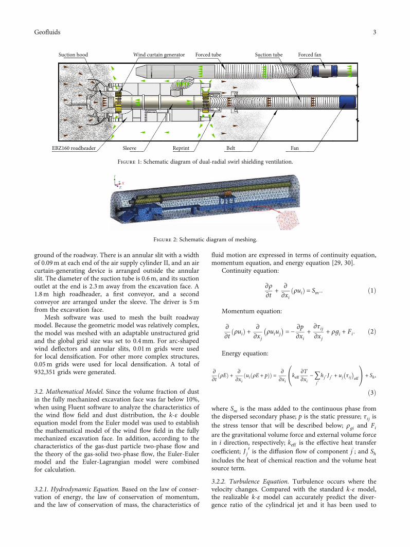
ground of the roadway. There is an annular slit with a widthof 0.09m at each end of the air supply cylinder II, and an aircurtain-generating device is arranged outside the annularslit. The diameter of the suction tube is 0.6m, and its suctionoutlet at the end is 2.3m away from the excavation face. A1.8m high roadheader, a first conveyor, and a secondconveyor are arranged under the sleeve. The driver is 5mfrom the excavation face.
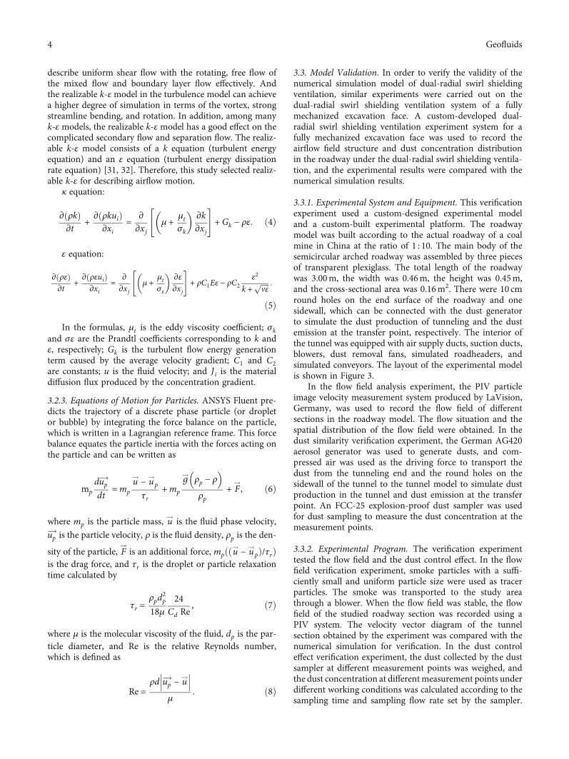
Mesh software was used to mesh the built roadwaymodel. Because the geometric model was relatively complex,the model was meshed with an adaptable unstructured gridand the global grid size was set to 0.4mm. For arc-shapedwind deflectors and annular slits, 0.01m grids were usedfor local densification. For other more complex structures,0.05m grids were used for local densification. A total of932,351 grids were generated.
3.2. Mathematical Model. Since the volume fraction of dustin the fully mechanized excavation face was far below 10%,when using Fluent software to analyze the characteristics ofthe wind flow field and dust distribution, the k-ε doubleequation model from the Euler model was used to establishthe mathematical model of the wind flow field in the fullymechanized excavation face. In addition, according to thecharacteristics of the gas-dust particle two-phase flow andthe theory of the gas-solid two-phase flow, the Euler-Eulermodel and the Euler-Lagrangian model were combinedfor calculation.
3.2.1. Hydrodynamic Equation. Based on the law of conser-vation of energy, the law of conservation of momentum,and the law of conservation of mass, the characteristics of
fluid motion are expressed in terms of continuity equation,momentum equation, and energy equation [29, 30].
Continuity equation:
∂ρ∂t
+ ∂∂xi
ρuið Þ = Sm:: ð1Þ
Momentum equation:
∂∂t
ρuið Þ + ∂∂xj
ρuiuj
� �= −
∂p∂xi
+∂τij∂xj
+ ρgi + Fi: ð2Þ
Energy equation:
∂∂t
ρEð Þ + ∂∂xi
ui ρE + pð Þð Þ = ∂∂xi
keff∂T∂xi
−〠j′hj′ J j′ + uj τij
� �eff
0@
1A + Sh,
ð3Þ
where Sm is the mass added to the continuous phase fromthe dispersed secondary phase; p is the static pressure; τij isthe stress tensor that will be described below; ρgi and Fi
are the gravitational volume force and external volume forcein i direction, respectively; keff is the effective heat transfercoefficient; J j′ is the diffusion flow of component j’; and Shincludes the heat of chemical reaction and the volume heatsource term.
3.2.2. Turbulence Equation. Turbulence occurs where thevelocity changes. Compared with the standard k-ε model,the realizable k-ε model can accurately predict the diver-gence ratio of the cylindrical jet and it has been used to
Suction hood Wind curtain generator Forced tube Suction tube Forced fan
FanBeltReprintSleeveEBZ160 roadheader
Figure 1: Schematic diagram of dual-radial swirl shielding ventilation.
Y
X
Z
Figure 2: Schematic diagram of meshing.
3Geofluids
describe uniform shear flow with the rotating, free flow ofthe mixed flow and boundary layer flow effectively. Andthe realizable k-ε model in the turbulence model can achievea higher degree of simulation in terms of the vortex, strongstreamline bending, and rotation. In addition, among manyk-ε models, the realizable k-ε model has a good effect on thecomplicated secondary flow and separation flow. The realiz-able k-ε model consists of a k equation (turbulent energyequation) and an ε equation (turbulent energy dissipationrate equation) [31, 32]. Therefore, this study selected realiz-able k-ε for describing airflow motion.
κ equation:
∂ ρkð Þ∂t
+ ∂ ρkuið Þ∂xi
= ∂∂xj
μ + μtσk
� �∂k∂xj
" #+ Gk − ρε: ð4Þ
ε equation:
∂ ρεð Þ∂t
+ ∂ ρεuið Þ∂xi
= ∂∂xj
μ + μtσε
� �∂ε∂xj
" #+ ρC1Eε − ρC2
ε2
k + ffiffiffiffiffivε
p :
ð5Þ
In the formulas, μt is the eddy viscosity coefficient; σkand σε are the Prandtl coefficients corresponding to k andε, respectively; Gk is the turbulent flow energy generationterm caused by the average velocity gradient; C1 and C2are constants; u is the fluid velocity; and Ji is the materialdiffusion flux produced by the concentration gradient.
3.2.3. Equations of Motion for Particles. ANSYS Fluent pre-dicts the trajectory of a discrete phase particle (or dropletor bubble) by integrating the force balance on the particle,which is written in a Lagrangian reference frame. This forcebalance equates the particle inertia with the forces acting onthe particle and can be written as
mp
dup!dt
=mp
u! − u!p
τr+mp
g! ρp − ρ� �ρp
+ F!, ð6Þ
where mp is the particle mass, u! is the fluid phase velocity,
up! is the particle velocity, ρ is the fluid density, ρp is the den-
sity of the particle, F!is an additional force, mpððu! − u!pÞ/τrÞ
is the drag force, and τr is the droplet or particle relaxationtime calculated by
τr =ρpd
2p
18μ24
Cd Re, ð7Þ
where μ is the molecular viscosity of the fluid, dp is the par-ticle diameter, and Re is the relative Reynolds number,which is defined as
Re =ρd up
!− u! μ
: ð8Þ
3.3. Model Validation. In order to verify the validity of thenumerical simulation model of dual-radial swirl shieldingventilation, similar experiments were carried out on thedual-radial swirl shielding ventilation system of a fullymechanized excavation face. A custom-developed dual-radial swirl shielding ventilation experiment system for afully mechanized excavation face was used to record theairflow field structure and dust concentration distributionin the roadway under the dual-radial swirl shielding ventila-tion, and the experimental results were compared with thenumerical simulation results.
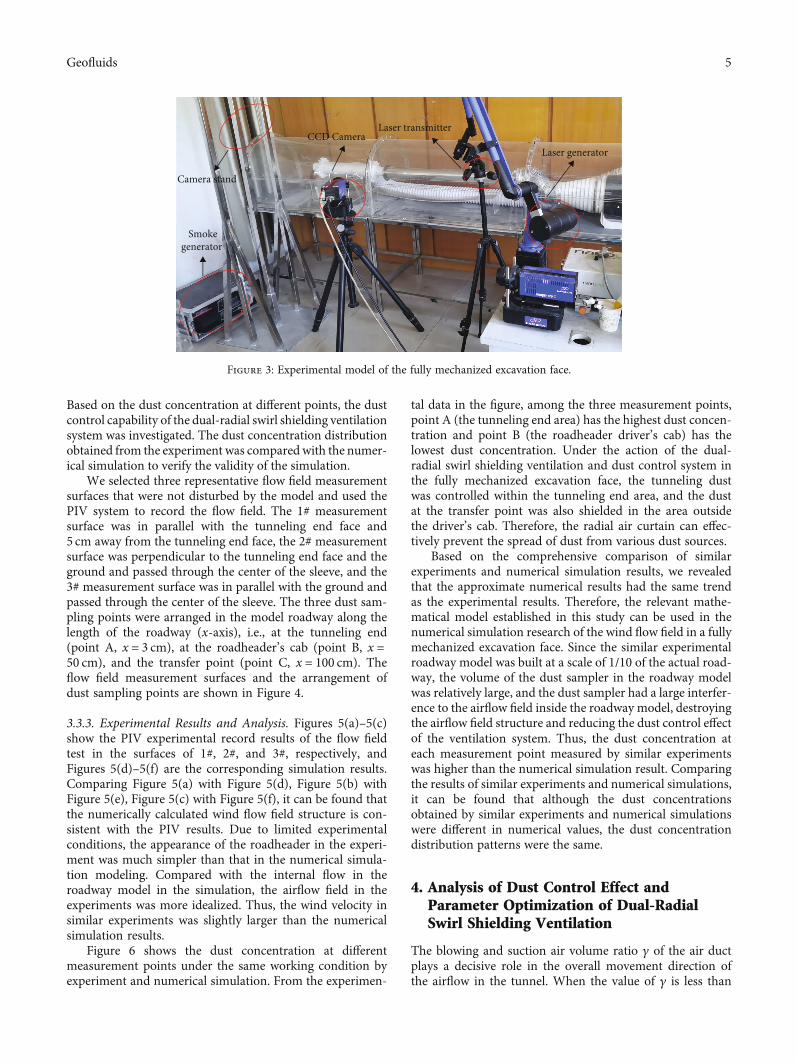
3.3.1. Experimental System and Equipment. This verificationexperiment used a custom-designed experimental modeland a custom-built experimental platform. The roadwaymodel was built according to the actual roadway of a coalmine in China at the ratio of 1 : 10. The main body of thesemicircular arched roadway was assembled by three piecesof transparent plexiglass. The total length of the roadwaywas 3.00m, the width was 0.46m, the height was 0.45m,and the cross-sectional area was 0.16m2. There were 10 cmround holes on the end surface of the roadway and onesidewall, which can be connected with the dust generatorto simulate the dust production of tunneling and the dustemission at the transfer point, respectively. The interior ofthe tunnel was equipped with air supply ducts, suction ducts,blowers, dust removal fans, simulated roadheaders, andsimulated conveyors. The layout of the experimental modelis shown in Figure 3.
In the flow field analysis experiment, the PIV particleimage velocity measurement system produced by LaVision,Germany, was used to record the flow field of differentsections in the roadway model. The flow situation and thespatial distribution of the flow field were obtained. In thedust similarity verification experiment, the German AG420aerosol generator was used to generate dusts, and com-pressed air was used as the driving force to transport thedust from the tunneling end and the round holes on thesidewall of the tunnel to the tunnel model to simulate dustproduction in the tunnel and dust emission at the transferpoint. An FCC-25 explosion-proof dust sampler was usedfor dust sampling to measure the dust concentration at themeasurement points.
3.3.2. Experimental Program. The verification experimenttested the flow field and the dust control effect. In the flowfield verification experiment, smoke particles with a suffi-ciently small and uniform particle size were used as tracerparticles. The smoke was transported to the study areathrough a blower. When the flow field was stable, the flowfield of the studied roadway section was recorded using aPIV system. The velocity vector diagram of the tunnelsection obtained by the experiment was compared with thenumerical simulation for verification. In the dust controleffect verification experiment, the dust collected by the dustsampler at different measurement points was weighed, andthe dust concentration at differentmeasurement points underdifferent working conditions was calculated according to thesampling time and sampling flow rate set by the sampler.
4 Geofluids
Based on the dust concentration at different points, the dustcontrol capability of the dual-radial swirl shielding ventilationsystem was investigated. The dust concentration distributionobtained from the experiment was compared with the numer-ical simulation to verify the validity of the simulation.
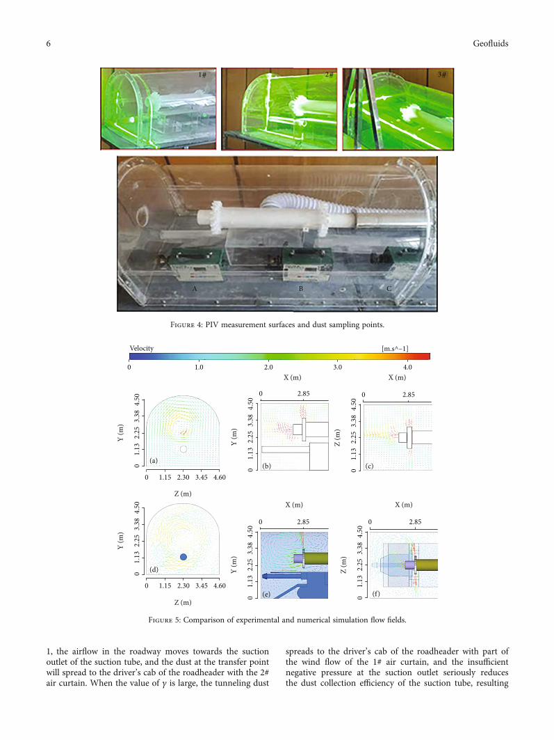
We selected three representative flow field measurementsurfaces that were not disturbed by the model and used thePIV system to record the flow field. The 1# measurementsurface was in parallel with the tunneling end face and5 cm away from the tunneling end face, the 2# measurementsurface was perpendicular to the tunneling end face and theground and passed through the center of the sleeve, and the3# measurement surface was in parallel with the ground andpassed through the center of the sleeve. The three dust sam-pling points were arranged in the model roadway along thelength of the roadway (x-axis), i.e., at the tunneling end(point A, x = 3 cm), at the roadheader’s cab (point B, x =50 cm), and the transfer point (point C, x = 100 cm). Theflow field measurement surfaces and the arrangement ofdust sampling points are shown in Figure 4.
3.3.3. Experimental Results and Analysis. Figures 5(a)–5(c)show the PIV experimental record results of the flow fieldtest in the surfaces of 1#, 2#, and 3#, respectively, andFigures 5(d)–5(f) are the corresponding simulation results.Comparing Figure 5(a) with Figure 5(d), Figure 5(b) withFigure 5(e), Figure 5(c) with Figure 5(f), it can be found thatthe numerically calculated wind flow field structure is con-sistent with the PIV results. Due to limited experimentalconditions, the appearance of the roadheader in the experi-ment was much simpler than that in the numerical simula-tion modeling. Compared with the internal flow in theroadway model in the simulation, the airflow field in theexperiments was more idealized. Thus, the wind velocity insimilar experiments was slightly larger than the numericalsimulation results.
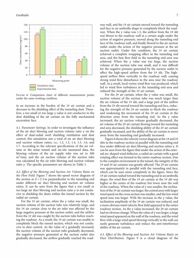
Figure 6 shows the dust concentration at differentmeasurement points under the same working condition byexperiment and numerical simulation. From the experimen-
tal data in the figure, among the three measurement points,point A (the tunneling end area) has the highest dust concen-tration and point B (the roadheader driver’s cab) has thelowest dust concentration. Under the action of the dual-radial swirl shielding ventilation and dust control system inthe fully mechanized excavation face, the tunneling dustwas controlled within the tunneling end area, and the dustat the transfer point was also shielded in the area outsidethe driver’s cab. Therefore, the radial air curtain can effec-tively prevent the spread of dust from various dust sources.
Based on the comprehensive comparison of similarexperiments and numerical simulation results, we revealedthat the approximate numerical results had the same trendas the experimental results. Therefore, the relevant mathe-matical model established in this study can be used in thenumerical simulation research of the wind flow field in a fullymechanized excavation face. Since the similar experimentalroadway model was built at a scale of 1/10 of the actual road-way, the volume of the dust sampler in the roadway modelwas relatively large, and the dust sampler had a large interfer-ence to the airflow field inside the roadway model, destroyingthe airflow field structure and reducing the dust control effectof the ventilation system. Thus, the dust concentration ateach measurement point measured by similar experimentswas higher than the numerical simulation result. Comparingthe results of similar experiments and numerical simulations,it can be found that although the dust concentrationsobtained by similar experiments and numerical simulationswere different in numerical values, the dust concentrationdistribution patterns were the same.
4. Analysis of Dust Control Effect andParameter Optimization of Dual-RadialSwirl Shielding Ventilation
The blowing and suction air volume ratio γ of the air ductplays a decisive role in the overall movement direction ofthe airflow in the tunnel. When the value of γ is less than
Smokegenerator
CCD CameraLaser transmitter
Laser generator
Camera stand
Figure 3: Experimental model of the fully mechanized excavation face.
5Geofluids
1, the airflow in the roadway moves towards the suctionoutlet of the suction tube, and the dust at the transfer pointwill spread to the driver’s cab of the roadheader with the 2#air curtain. When the value of γ is large, the tunneling dust
spreads to the driver’s cab of the roadheader with part ofthe wind flow of the 1# air curtain, and the insufficientnegative pressure at the suction outlet seriously reducesthe dust collection efficiency of the suction tube, resulting
1# 2# 3#
A B C
Figure 4: PIV measurement surfaces and dust sampling points.
Y (m
)
4.50
3.38
2.25
1.13
0
Y (m
)
4.50
3.38
2.25
1.13
0
Y (m
)
4.50
3.38
2.25
1.13
0
Y (m
)
4.50
3.38
2.25
1.13
0
Z (m
)
4.50
3.38
2.25
1.13
0
Z (m
)
4.50
3.38
2.25
1.13
0
0 2.85
X (m)
Z (m)
0 1.15 2.30 3.45 4.60
0 2.85
Z (m)
0 1.15 2.30 3.45 4.60
0 2.85
X (m)
2.85
X (m)
0
X (m)
Velocity
0 1.0 2.0 3.0 4.0
[m.s^–1]
(a)(b) (c)
(d)
(e) (f)
Figure 5: Comparison of experimental and numerical simulation flow fields.
6 Geofluids
in an increase in the burden of the 1# air curtain and adecrease in the shielding effect of the tunneling dust. There-fore, a too small or too large γ value is not conducive to thedust shielding of the air curtain on the fully mechanizedexcavation face.
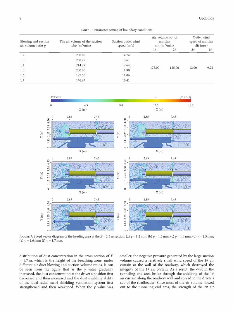
4.1. Parameter Settings. In order to investigate the influenceof the air duct blowing and suction volume ratio γ on theeffect of dual-radial swirl shielding ventilation and dustcontrol, this simulation sets a total of six air duct blowingand suction volume ratios, i.e., 1.2, 1.3, 1.4, 1.5, 1.6, and1.7. According to the relevant specifications of the air vol-ume in the mine tunnel and on-site measured data, theblowing volume of the air supply tube was set to 300m3/min, and the air suction volume of the suction tubewas calculated by the air tube blowing and suction volumeratio γ. The specific parameters are shown in Table 1.
4.2. Effect of the Blowing and Suction Air Volume Ratio onthe Flow Field. Figure 7 shows the speed vector diagram ofthe section at Z = 2:3m perpendicular to the tunneling endunder different air duct blowing and suction air volumeratios. It can be seen from the figure that a too small ortoo large air duct blowing and suction ratio γ is not condu-cive to shielding the dusts within the tunnel section by theradial air curtain.
For the 1# air curtain, when the γ value was small, thesuction volume of the suction tube was relatively large, andthe 1# air curtain close to the air inlet was affected by thelarge negative pressure at the suction outlet, and the airflowfrom the 1# slit was caught by the suction tube before reach-ing the roadway. As a result, the 1# air curtain was unable tocompletely block the tunnel section, which was not condu-cive to dust control. As the value of γ gradually increased,the suction volume of the suction tube gradually decreased,the negative pressure generated at the suction outlet alsogradually decreased, the airflow gradually reached the road-
way wall, and the 1# air curtain moved toward the tunnelingend face in an umbrella shape to completely block the road-way. When the γ value was 1.5, the airflow from the 1# slitwas blown to the roadway wall at a certain angle under theaction of negative pressure, moved along the tunneling endface of the roadway wall, and finally flowed to the air suctionoutlet under the action of the negative pressure at the airsuction outlet. Under this condition, the 1# air curtainachieved a complete wrapping effect in the tunneling endarea, and the best flow field in the tunneling end area wasachieved. When the γ value was too large, the suctionvolume of the suction tube was small, and it was difficultfor the negative pressure generated by the suction outlet toaffect the high-speed airflow from the 1# slit. The high-speed airflow blew vertically to the roadway wall, causingstrong wind flow disturbance in the area near the roadwaywall. As a result, local vortex wind flow was produced, whichled to wind flow turbulence in the tunneling end area andreduced the strength of the 1# air curtain.
For the 2# air curtain, when the γ value was small, thesuction volume of the suction tube was much larger thanthe air volume of the 1# slit, and a large part of the airflowfrom the 2# slit moved toward the tunneling end face, reduc-ing the strength of the 2# air curtain to block the roadwayand weakening the movement of the 2# air curtain in thedirection away from the tunneling end. As the γ valueincreased, the air suction volume gradually decreased, theair volume of the 2# air curtain flowing toward the tunnelingend area decreased, the shielding ability of the 2# air curtaingradually increased, and the ability of the air curtain to moveaway from the tunneling end gradually increased.
Figure 8 shows the velocity vector diagram at the 1# and 2#slits in the roadway section in parallel with the tunneling endface under different air duct blowing and suction ratios γ. Itcan be seen from the figure that under the action of the exter-nal arc-shaped wind deflector, a radial air curtain with a goodrotating effect was formed in the entire roadway section. Dueto the complex environment in the tunnel, the integrity of the1# and 2# air curtains was greatly affected. The 2# air curtainwas approximately in parallel with the tunneling end face,which can be seen more completely in the figure. Since the1# air curtain rushed toward the tunneling end in an umbrellashape, the wind flow of the 1# air curtain at the 1# slit washigher at the center of the roadway but lower near the wallof the roadway. When the value of γ was smaller, the inclina-tion of the 1# air curtainwas larger, the central areawith largerwind speed on the cross section was smaller, and the lowwindspeed area was larger. With the increase in the γ value, theinclination amplitude of the 1# air curtain was reduced, anda more obvious wind velocity flow field appeared in the entireroadway section. As the γ value increased, the 2# air curtainhad no obvious change.When the value of γwas larger, a largewind speed appeared on the wall of the roadway, and the windflow with a large wind speed blowing vertically to the wall caneasily generate turbulence and reduce the anti-interferenceability of the air curtain.
4.3. Effect of the Blowing and Suction Air Volume Ratio onDust Distribution. Figure 9 is a cloud diagram of the
112
127140
120
100
80
60
40
20
0
45
A BMeasuring point
C
52
Simulation dataExperimental data
Dus
t con
cent
ratio
n (m
g/m
3 )
4638
Figure 6: Comparison chart of different measurement pointsunder the same working condition.
7Geofluids
distribution of dust concentration in the cross section of Y= 1:7m, which is the height of the breathing zone, underdifferent air duct blowing and suction volume ratios. It canbe seen from the figure that as the γ value graduallyincreased, the dust concentration at the driver’s position firstdecreased and then increased and the dust shielding abilityof the dual-radial swirl shielding ventilation system firststrengthened and then weakened. When the γ value was
smaller, the negative pressure generated by the large suctionvolume caused a relatively small wind speed of the 1# aircurtain at the wall of the roadway, which destroyed theintegrity of the 1# air curtain. As a result, the dust in thetunneling end area broke through the shielding of the 1#air curtain along the roadway wall and spread to the driver’scab of the roadheader. Since most of the air volume flowedout to the tunneling end area, the strength of the 2# air
0 2.85 7.45
X (m)
Y (m
) 3.38
4.50
2.25
1.13
0
Y (m
) 3.38
4.50
2.25
1.13
0
Y (m
) 3.38
4.50
2.25
1.13
0
Y (m
) 3.38
4.50
2.25
1.13
0
Y (m
) 3.38
4.50
2.25
1.13
0
Y (m
) 3.38
4.50
2.25
1.13
0
0 2.85 7.45
X (m)
0 2.85 7.45
X (m)
0 2.85 7.45
X (m)
0 2.85 7.45
X (m)
0 2.85 7.45
X (m)
(a)
(c)
(e)
(d)
(f)
(b)
Velocity [m.s^–1]
0 4.5 9.0 13.5 18.0
Figure 7: Speed vector diagram of the heading area at the Z = 2:3m section: (a) γ = 1:2mm; (b) γ = 1:3mm; (c) γ = 1:4mm; (d) γ = 1:5mm;(e) γ = 1:6mm; (f) γ = 1:7mm.
Table 1: Parameter setting of boundary conditions.
Blowing and suctionair volume ratio γ
The air volume of the suctiontube (m3/min)
Suction outlet windspeed (m/s)
Air volume out ofannular
slit (m3/min)
Outlet windspeed of annular
slit (m/s)1# 2# 3# 4#
1.2 250.00 14.74
175.00 125.00 12.90 9.22
1.3 230.77 13.61
1.4 214.29 12.64
1.5 200.00 11.80
1.6 187.50 11.06
1.7 176.47 10.41
8 Geofluids
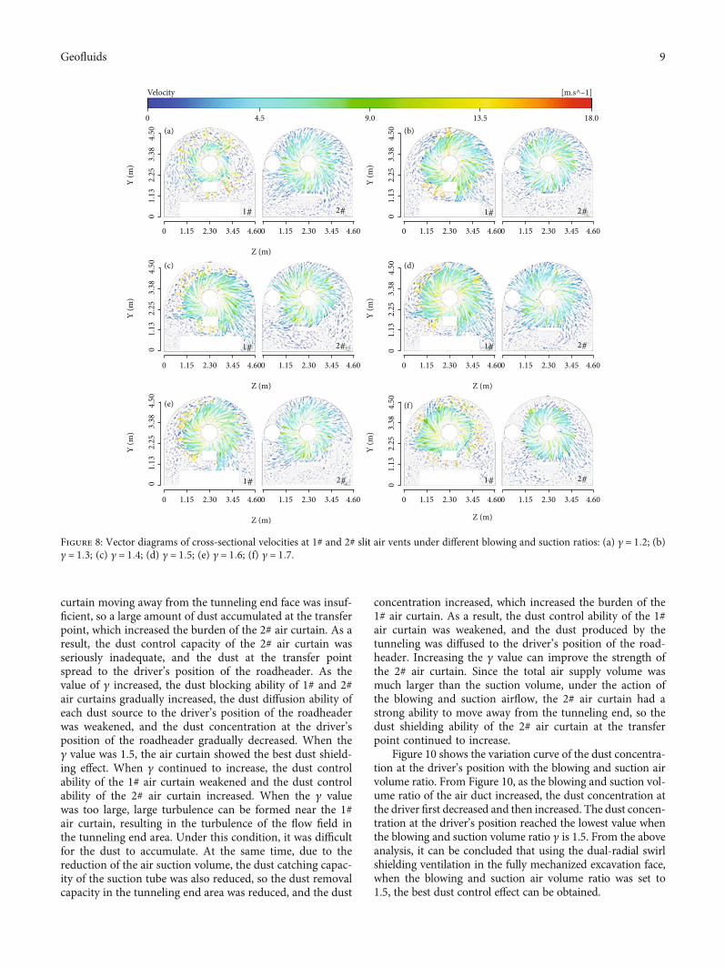
curtain moving away from the tunneling end face was insuf-ficient, so a large amount of dust accumulated at the transferpoint, which increased the burden of the 2# air curtain. As aresult, the dust control capacity of the 2# air curtain wasseriously inadequate, and the dust at the transfer pointspread to the driver’s position of the roadheader. As thevalue of γ increased, the dust blocking ability of 1# and 2#air curtains gradually increased, the dust diffusion ability ofeach dust source to the driver’s position of the roadheaderwas weakened, and the dust concentration at the driver’sposition of the roadheader gradually decreased. When theγ value was 1.5, the air curtain showed the best dust shield-ing effect. When γ continued to increase, the dust controlability of the 1# air curtain weakened and the dust controlability of the 2# air curtain increased. When the γ valuewas too large, large turbulence can be formed near the 1#air curtain, resulting in the turbulence of the flow field inthe tunneling end area. Under this condition, it was difficultfor the dust to accumulate. At the same time, due to thereduction of the air suction volume, the dust catching capac-ity of the suction tube was also reduced, so the dust removalcapacity in the tunneling end area was reduced, and the dust
concentration increased, which increased the burden of the1# air curtain. As a result, the dust control ability of the 1#air curtain was weakened, and the dust produced by thetunneling was diffused to the driver’s position of the road-header. Increasing the γ value can improve the strength ofthe 2# air curtain. Since the total air supply volume wasmuch larger than the suction volume, under the action ofthe blowing and suction airflow, the 2# air curtain had astrong ability to move away from the tunneling end, so thedust shielding ability of the 2# air curtain at the transferpoint continued to increase.
Figure 10 shows the variation curve of the dust concentra-tion at the driver’s position with the blowing and suction airvolume ratio. From Figure 10, as the blowing and suction vol-ume ratio of the air duct increased, the dust concentration atthe driver first decreased and then increased. The dust concen-tration at the driver’s position reached the lowest value whenthe blowing and suction volume ratio γ is 1.5. From the aboveanalysis, it can be concluded that using the dual-radial swirlshielding ventilation in the fully mechanized excavation face,when the blowing and suction air volume ratio was set to1.5, the best dust control effect can be obtained.
4.50
3.38
2.25
1.13
0
Y (m
)
4.50
3.38
2.25
1.13
0
Y (m
)
4.50
3.38
2.25
1.13
0
Y (m
)
4.50
3.38
2.25
1.13
0
Y (m
)
4.50
3.38
2.25
1.13
0
Y (m
)
4.50
3.38
2.25
1.13
0
Y (m
)
0 1.15 2.30 4.603.45 0 1.15 2.30 4.603.45
Z (m)
0 1.15 2.30 4.603.45 0 1.15 2.30 4.603.45
Z (m)
0 1.15 2.30 4.603.45 0 1.15 2.30 4.603.45
Z (m)
Z (m)
Z (m)
0 1.15 2.30 4.603.45 0 1.15 2.30 4.603.45
0 1.15 2.30 4.603.45 0 1.15 2.30 4.603.45
0 1.15 2.30 4.603.45 0 1.15 2.30 4.603.45
0 4.5 9.0 13.5 18.0
Velocity [m.s^–1]
(a) (b)
(c)
(e)
(d)
(f)
1# 2# 1# 2#
1# 2#1# 2#
1# 2# 1# 2#
Figure 8: Vector diagrams of cross-sectional velocities at 1# and 2# slit air vents under different blowing and suction ratios: (a) γ = 1:2; (b)γ = 1:3; (c) γ = 1:4; (d) γ = 1:5; (e) γ = 1:6; (f) γ = 1:7.
9Geofluids
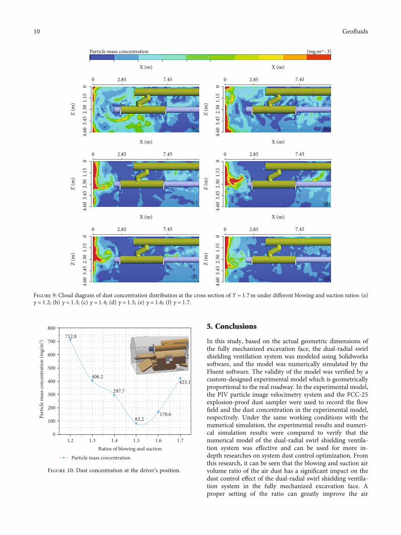
5. Conclusions
In this study, based on the actual geometric dimensions ofthe fully mechanized excavation face, the dual-radial swirlshielding ventilation system was modeled using Solidworkssoftware, and the model was numerically simulated by theFluent software. The validity of the model was verified by acustom-designed experimental model which is geometricallyproportional to the real roadway. In the experimental model,the PIV particle image velocimetry system and the FCC-25explosion-proof dust sampler were used to record the flowfield and the dust concentration in the experimental model,respectively. Under the same working conditions with thenumerical simulation, the experimental results and numeri-cal simulation results were compared to verify that thenumerical model of the dual-radial swirl shielding ventila-tion system was effective and can be used for more in-depth researches on system dust control optimization. Fromthis research, it can be seen that the blowing and suction airvolume ratio of the air dust has a significant impact on thedust control effect of the dual-radial swirl shielding ventila-tion system in the fully mechanized excavation face. Aproper setting of the ratio can greatly improve the air
01.
152.
303.
454.
600 2.85 7.45
X (m)Z
(m)
01.
152.
303.
454.
60
Z (m
)
01.
152.
303.
454.
60
Z (m
)
01.
152.
303.
454.
60
Z (m
)
01.
152.
303.
454.
60
Z (m
)
01.
152.
303.
454.
60
Z (m
)
0 2.85 7.45
X (m)
0 2.85 7.45
X (m)
0 2.85 7.45
X (m)
0 2.85 7.45
X (m)
0 2.85 7.45
X (m)
Particle mass concentration [mg.m^–3]
(a)
(c)
(e) (f)
(d)
(b)
Figure 9: Cloud diagram of dust concentration distribution at the cross section of Y = 1:7m under different blowing and suction ratios: (a)γ = 1:2; (b) γ = 1:3; (c) γ = 1:4; (d) γ = 1:5; (e) γ = 1:6; (f) γ = 1:7.
800
700
600
500
400
Part
icle
mas
s con
cent
ratio
n (m
g/m
3 )
Particle mass concentrationRatios of blowing and suction
300
200
100
01.2
406.2
712.8
297.7
83.2170.6
423.1
Driver
1.3 1.4 1.5 1.6 1.7
Figure 10: Dust concentration at the driver’s position.
10 Geofluids
organization of the dual-radial swirl shielding ventilationsystem, thereby improving the dust control effect of the sys-tem. A too small blowing and suction air volume ratiodestroyed the integrity of the 1# air curtain that was usedto block the roadway section. A too large blowing and suc-tion air volume ratio led to gradual turbulence of airflowand local circulating air. Therefore, a too large or too smallblowing and suction volume ratio can decrease the dust con-trol capability of the ventilation system. As the blowing andsuction volume ratio of the air duct increased, the dust con-trol effect of the dual-radial swirl shielding ventilation sys-tem showed a trend of first strengthening and thenweakening. When the blowing and suction air volume ratioof the air duct was 1.5, the dust shielding effect was the best.
Due to the limitation of research time and experimentalconditions, as well as the complex equipment layout andoperation process of the actual fully mechanized miningface, the research results need to be further tested on-site.
Data Availability
Data sharing is not applicable to this article as no datasetswere generated or analyzed during the current study.
Conflicts of Interest
The authors declare that they have no conflicts of interest.
Acknowledgments
This research was financially supported by the NationalNatural Science Foundation of China (51774135, 51974120),the Hunan Postgraduate Research and Innovation FundingProject (CX2018B657), and theOpenFundProject of SouthernCoal Mine Gas and Roof Disaster Prevention and ControlWork Safety Key Laboratory (E21825).
References
[1] Y. H. Liu, W. Nie, Y. B. Mu et al., “A synthesis and perfor-mance evaluation of a highly efficient ecological dust depressorbased on the sodium lignosulfonate-acrylic acid graft copoly-mer,” RSC Advances, vol. 8, no. 21, pp. 11498–11508, 2018.
[2] S. Yin, W. Nie, L. Guo et al., “CFD simulations of air curtaindust removal effect by ventilation parameters during tunnel-ing,” Advanced Powder Technology, vol. 31, no. 6, pp. 2456–2468, 2020.
[3] B. Tan, H. Liu, B. Xu, and T. Wang, “Comparative study of theexplosion pressure characteristics of micro- and nano-sizedcoal dust and methane–coal dust mixtures in a pipe,” Interna-tional Journal of Coal Science & Technology, vol. 7, no. 1,pp. 68–78, 2020.
[4] P. F. Wang, X. H. Tan, W. M. Cheng, G. Guo, and R. H. Liu,“Dust removal efficiency of high pressure atomization inunderground coal mine, International Journal of Mining Sci-ence and Technology,” vol. 28, no. 4, pp. 685–690, 2018.
[5] P. F. Wang, K. Zhang, and R. H. Liu, “Influence of air supplypressure on atomization characteristics and dust-suppressionefficiency of internal-mixing air-assisted atomizing nozzle,”Powder Technology, vol. 355, pp. 393–407, 2019.
[6] Y. J. Li, P. F. Wang, R. H. Liu, Y. D. Jiang, and H. Han, “Deter-mination of the optimal axial-to-radial flow ratio of the wall-mounted swirling ventilation in fully mechanized excavationface,” Powder Technology, vol. 360, pp. 890–910, 2020.
[7] Q. Bao, W. Nie, C. Q. Liu et al., “The preparation of a novelhydrogel based on crosslinked polymers for suppressing coaldusts,” Journal of Cleaner Production, vol. 294, p. 1193, 2019.
[8] P. F. Wang, Y. J. Shi, L. Y. Zhang, and Y. J. Li, “Effect of struc-tural parameters on atomization characteristics and dustreduction performance of internal-mixing air-assisted atom-izer nozzle,” Process Safety and Environmental Protection,vol. 128, pp. 316–328, 2019.
[9] H. Han, P. F. Wang, Y. J. Li, R. H. Liu, and C. Tian, “Effect ofwater supply pressure on atomization characteristics and dust-reduction efficiency of internal mixing air atomizing nozzle,”Advanced Powder Technology., vol. 31, no. 1, pp. 252–268,2020.
[10] Q. Liu, W. Nie, Y. Hua, H. T. Peng, and Z. Q. Liu, “The effectsof the installation position of a multi-radial swirling air- cur-tain generator on dust diffusion and pollution rules in afully-mechanized excavation face: a case study,” Powder Tech-nology, vol. 329, pp. 371–385, 2018.
[11] P. F. Wang, R. Z. Gao, R. H. Liu, and F. Q. Yang, “CFD-based optimization of the installation location of the wall-mounted air duct in a fully mechanized excavation face,”Process Safety and Environmental Protection, vol. 141,pp. 234–245, 2020.
[12] S. Akhshik, M. Behzad, and M. Rajabi, “CFD-DEM approachto investigate the effect of drill pipe rotation on cuttings trans-port behavior,” Journal of Petroleum Science and Engineering,vol. 127, pp. 229–244, 2015.
[13] D. W. Chen, W. Nie, P. Cai, and Z. Q. Liu, “The diffusion ofdust in a fully-mechanized mining face with a mining heightof 7 m and the application of wet dust-collecting nets,” Journalof Cleaner Production, vol. 205, pp. 463–476, 2018.
[14] Z. A. Jiang, “Study on similarity of gas-solid two-phase flow inventilation and dust removal,” Coal Engineer, vol. 40, pp. 12–15, 1993.
[15] F. Camelli, G. Byrne, and R. Löhner, “Modeling subway airflow using CFD,” Tunneling and Underground Space Technol-ogy, vol. 43, pp. 20–31, 2014.
[16] Z. A. Jiang, P. Yan, J. S. Chen, and Z. Y. Zhang, “Optimizationon parameters of long distance forced and short distanceexhausted ventilation system in mine rock heading roadway,”Coal Science and Technology, vol. 43, pp. 54–58, 2019.
[17] S. Y. Hu, Q. Liao, G. R. Feng et al., “Numerical study of gas-solid two-phase flow around road-header drivers in a fullymechanized excavation face,” Powder Technology, vol. 344,pp. 959–969, 2019.
[18] Z. Korecki and W. Skoczynski, “KOMAG mining mechaniza-tion center-service to the cause of mining from 1945-1985,”Mechanizacja Automatyzacja Gornictwa, vol. 24, pp. 12–26,1986.
[19] C. Q. Liu, W. Nie, Q. Bao, Q. Liu, C. H. Wei, and Y. Hua, “Theeffects of the pressure outlet's position on the diffusion andpollution of dust in tunnel using a shield tunneling machine,”Energy & Buildings, vol. 176, pp. 232–245, 2018.
[20] W. Nie, W. L. Wei, P. Cai et al., “Simulation experiments onthe controllability of dust diffusion by means of multi-radialvortex airflow,” Advanced Powder Technology, vol. 29, no. 3,pp. 835–847, 2018.
11Geofluids
[21] X. F. Ren, X. M. Hu, D. Xue et al., “Novel sodium silicate/po-lymer composite gels for the prevention of spontaneous com-bustion of coal,” Journal of Hazardous Materials, vol. 371,pp. 643–654, 2019.
[22] Z. Q. Liu, W. Nie, H. T. Peng, S. B. Yang, D. W. Chen, andQ. Liu, “The effects of the spraying pressure and nozzle orificediameter on the atomizing rules and dust suppression perfor-mances of an external spraying system in a fully-mechanizedexcavation face,” Powder Technology, vol. 350, pp. 62–80,2019.
[23] J. P. Minier, “On Lagrangian stochastic methods for turbulentpolydisperse two-phase reactive flows,” Progress in Energy andCombustion Science, vol. 50, pp. 1–62, 2015.
[24] W. Nie, W. L. Wei, X. Ma, Y. H. Liu, H. T. Peng, and Q. Liu,“The effects of ventilation parameters on the migration behav-iors of head-on dusts in the heading face,” Tunnelling andUnderground Space Technology, vol. 70, pp. 400–408, 2017.
[25] Q. Zhou, B. T. Qin, F. Wang, H. T. Wang, J. Hou, and Z. R.Wang, “Effects of droplet formation patterns on the atomiza-tion characteristics of a dust removal spray in a coal cutter,”Powder Technology, vol. 344, pp. 570–580, 2019.
[26] Y. J. Shi, P. F. Wang, R. H. Liu, X. H. Tan, and W. Zhang,“Numerical simulation and engineering application of coalbedwater injection,” Mathematical Problems in Engineering,vol. 2019, Article ID 6309160, 12 pages, 2019.
[27] P. F. Wang, Y. J. Li, R. H. Liu, and Y. J. Shi, “Effects of forced-to-exhaust ratio of air volume on dust control of wall- attachedswirling ventilation for mechanized excavation face,” Tunnel-ling and Underground Space Technology., vol. 90, pp. 194–207, 2019.
[28] C. Tan, Z. A. Jiang, M. Wang, and Y. Chen, “Similarity exper-iment on multi-source dust diffusion law in fully mechanizedcaving face,” China National Coal Association, vol. 40,pp. 122–127, 2015.
[29] Q. Zhou, B. T. Qin, F. Wang, and H. T. Wang, “Experimentalinvestigation on the performance of a novel magnetized appa-ratus used to improve the dust suppression ability ofsurfactant-magnetized water,” Powder Technology, vol. 354,pp. 149–157, 2019.
[30] W. J. Yin, G. Zhou, and D. H. Gao, “Simulation analysis andengineering application of distribution characteristics aboutmulti-stage atomization field for cutting dust in fully mecha-nized mining face,” Advanced Powder Technology, vol. 30,no. 11, pp. 2600–2615, 2019.
[31] S. Yin, W. Nie, Q. Liu, and Y. Hua, “Transient CFD modellingof space-time evolution of dust pollutants and air- curtain gen-erator position during tunneling,” Journal of Cleaner Produc-tion, vol. 239, article 117924, 2019.
[32] B. Sun, W.M. Cheng, J. Y.Wang, and H.Wang, “Effects of tur-bulent airflow from coal cutting on pollution characteristics ofcoal dust in fully-mechanized mining face: a case study,” Jour-nal of Cleaner Production, vol. 201, pp. 308–324, 2018.
12 Geofluids