Embed Size (px)
Citation preview

Chap. 7Illumination-based Shading
Ensino de Informática (3326) - 4º ano, 2º semestreEngenharia Electrotécnica (2287) - 5º ano, 2º semestre
Engenharia Informática (2852) - 4º ano, 2º semestre
Lighting Review
Lighting Models Ambient
− Normals don’t matter
Lambert/Diffuse− Angle between surface normal and light
Phong/Specular− Surface normal, light, and viewpoint
Applying Illumination
We now have an direct illumination model for a single point ona surface
Assuming that our surface is defined as a mesh of polygonalfacets, which points should we use? Computing these models for every point that is displayed is expensive
Normals may not be explicitly stated for every point
Keep in mind: It’s a fairly expensive calculation
Several possible answers, each with different implications for the visualquality of the result

Shading Models
Several options: Flat shading
Gouraud shading (interpolation)
Phong shading (interpolation)
New hardware does per-pixel programmable shading!
Flat (or Constant) Shading
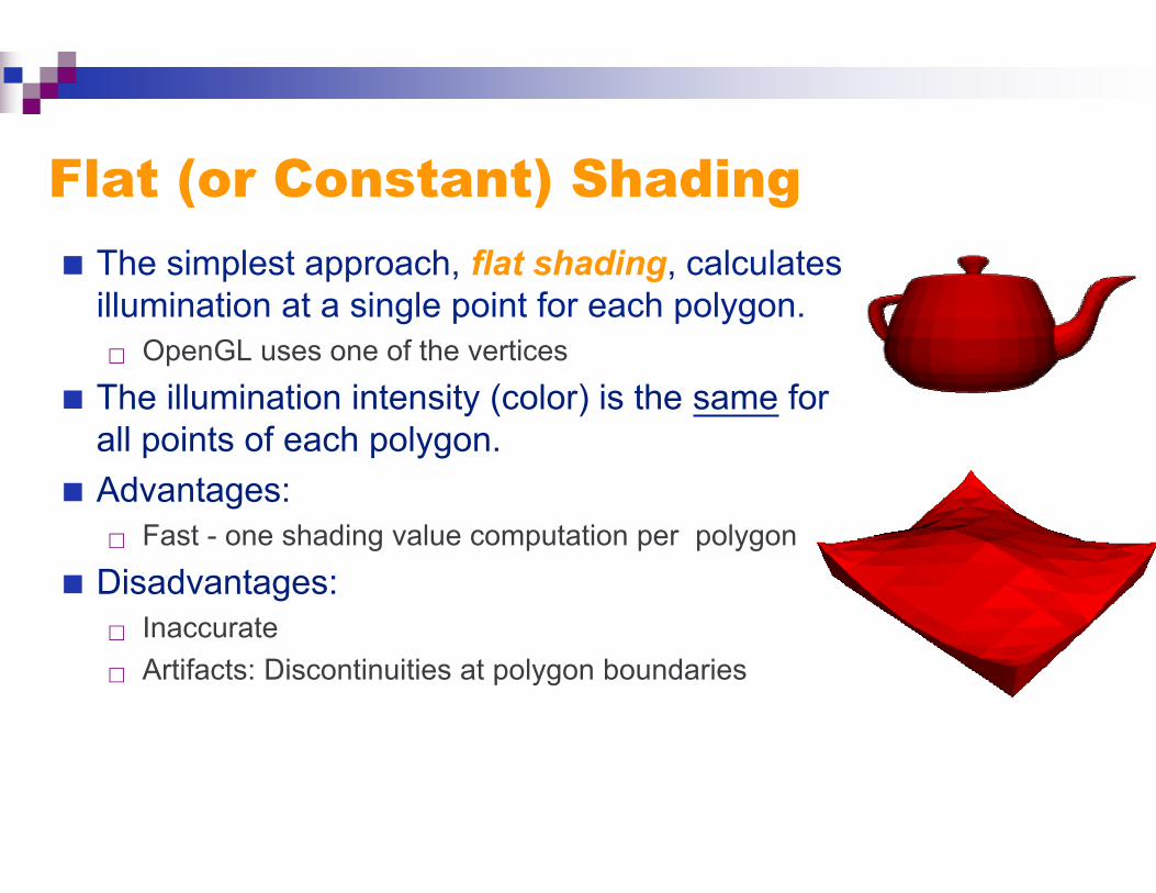
The simplest approach, flat shading, calculatesillumination at a single point for each polygon. OpenGL uses one of the vertices
The illumination intensity (color) is the same forall points of each polygon.
Advantages: Fast - one shading value computation per polygon
Disadvantages: Inaccurate
Artifacts: Discontinuities at polygon boundaries
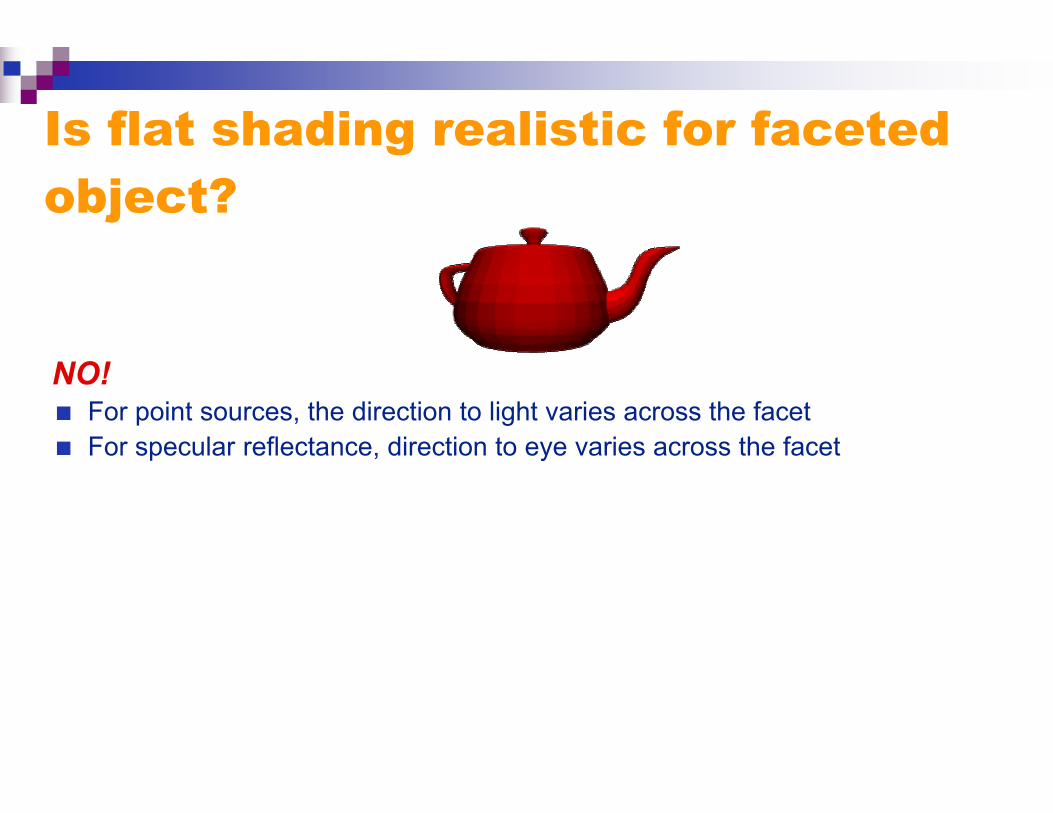
Is flat shading realistic for facetedobject?
NO! For point sources, the direction to light varies across the facet For specular reflectance, direction to eye varies across the facet
Flat Shading
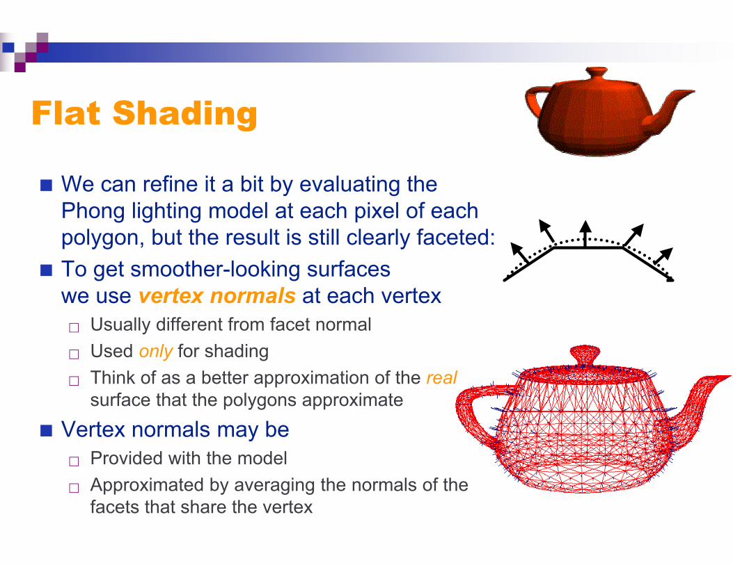
We can refine it a bit by evaluating thePhong lighting model at each pixel of eachpolygon, but the result is still clearly faceted:
To get smoother-looking surfaceswe use vertex normals at each vertex Usually different from facet normal
Used only for shading
Think of as a better approximation of the realsurface that the polygons approximate
Vertex normals may be Provided with the model
Approximated by averaging the normals of thefacets that share the vertex
Gouraud Shading
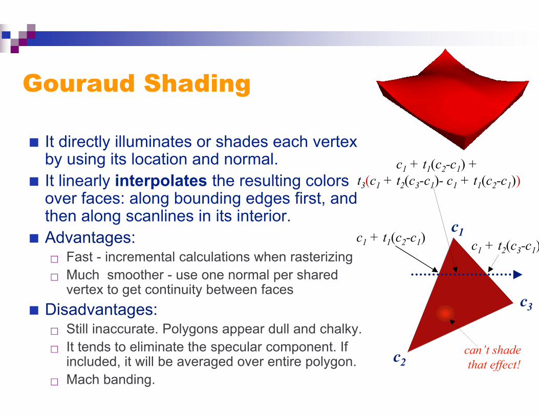
It directly illuminates or shades each vertexby using its location and normal.
It linearly interpolates the resulting colorsover faces: along bounding edges first, andthen along scanlines in its interior.
Advantages: Fast - incremental calculations when rasterizing Much smoother - use one normal per shared
vertex to get continuity between faces
Disadvantages: Still inaccurate. Polygons appear dull and chalky. It tends to eliminate the specular component. If
included, it will be averaged over entire polygon. Mach banding.
c1
c2
c3
c1 + t1(c2-c1) c1 + t2(c3-c1)
c1 + t1(c2-c1) + t3(c1 + t2(c3-c1)- c1 + t1(c2-c1))
can’t shade that effect!
Gouraud Shading:Mach banding
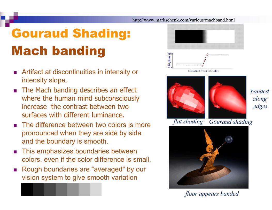
Artifact at discontinuities in intensity orintensity slope.
The Mach banding describes an effectwhere the human mind subconsciouslyincrease the contrast between twosurfaces with different luminance.
The difference between two colors is morepronounced when they are side by sideand the boundary is smooth.
This emphasizes boundaries betweencolors, even if the color difference is small.
Rough boundaries are “averaged” by ourvision system to give smooth variation
http://www.markschenk.com/various/machband.html
floor appears banded
banded along edges
flat shading Gouraud shading

OpenGL shading
OpenGL defines two particular shading models:
Controls how colors are assigned to pixels
Gouraud shading:interpolates between the colors at the vertices (thedefault)
glShadeModel(GL_SMOOTH)
Flat shading: uses a constant color across the polygon
glShadeModel(GL_FLAT)
Phong Shading
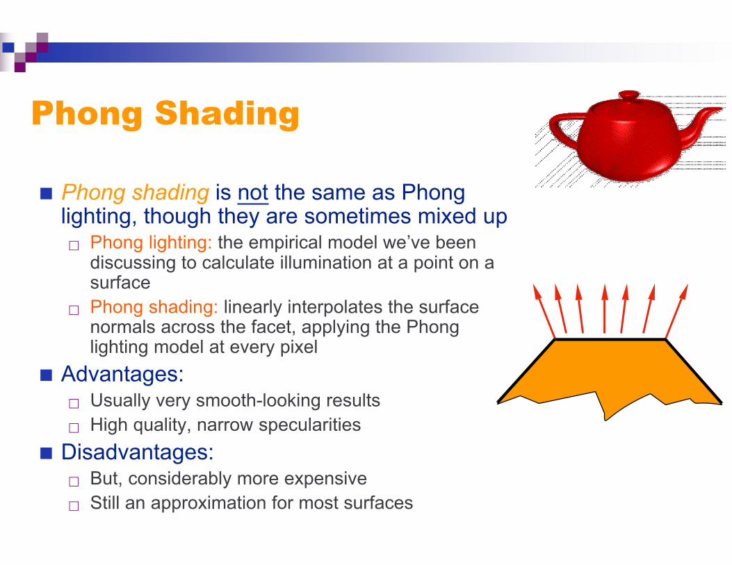
Phong shading is not the same as Phonglighting, though they are sometimes mixed up Phong lighting: the empirical model we’ve been
discussing to calculate illumination at a point on asurface
Phong shading: linearly interpolates the surfacenormals across the facet, applying the Phonglighting model at every pixel
Advantages: Usually very smooth-looking results High quality, narrow specularities
Disadvantages: But, considerably more expensive Still an approximation for most surfaces

Phong Shading
Linearly interpolate the vertexnormals Compute lighting equations at each
pixel
Can use specular component
Note that normals are used tocompute diffuse and specular terms
N1
N2
N3
N4
discontinuity in normal’s rate of change is harder to detect
Itotal = KAIA + Ii
i=1
# lights
∑ (KD
N ⋅Li( ) + KS
V ⋅Ri( )n )
Shortcomings of Shading Polygonal silhouettes remain
Perspective distortion
Interpolation dependent on the polygon orientation
Problems at shared vertices
Bad vertex averaging
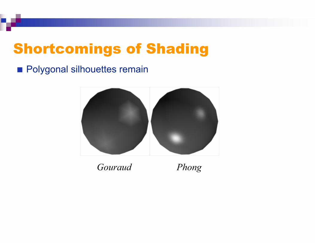
Shortcomings of Shading Polygonal silhouettes remain
Gouraud Phong
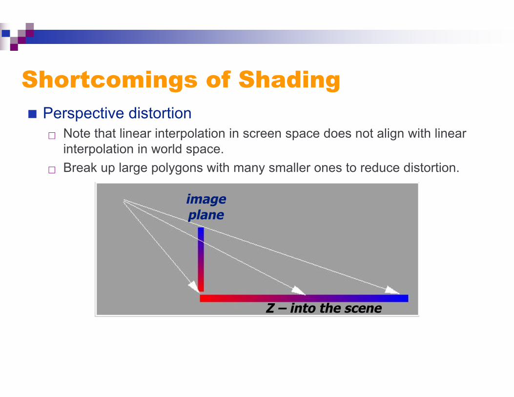
Shortcomings of Shading Perspective distortion
Note that linear interpolation in screen space does not align with linearinterpolation in world space.
Break up large polygons with many smaller ones to reduce distortion.
Z – into the scene
imageplane
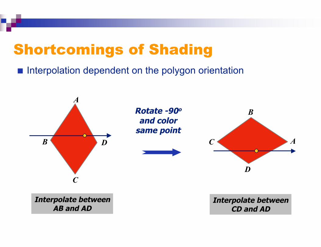
Shortcomings of Shading Interpolation dependent on the polygon orientation
A
D
C
B
Interpolate betweenAB and AD
Rotate -90o
and colorsame point
Interpolate betweenCD and AD
D
C A
B
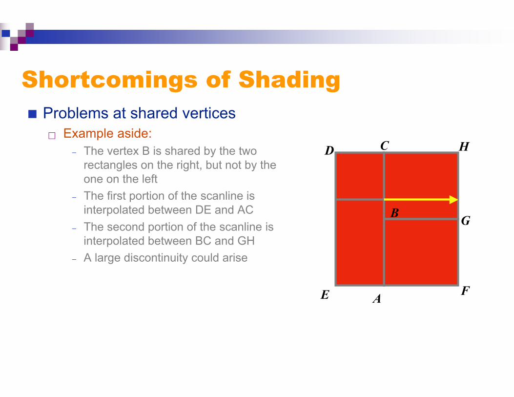
Shortcomings of Shading Problems at shared vertices
Example aside:− The vertex B is shared by the two
rectangles on the right, but not by theone on the left
− The first portion of the scanline isinterpolated between DE and AC
− The second portion of the scanline isinterpolated between BC and GH
− A large discontinuity could arise
B
A
C
E
D
F
H
G
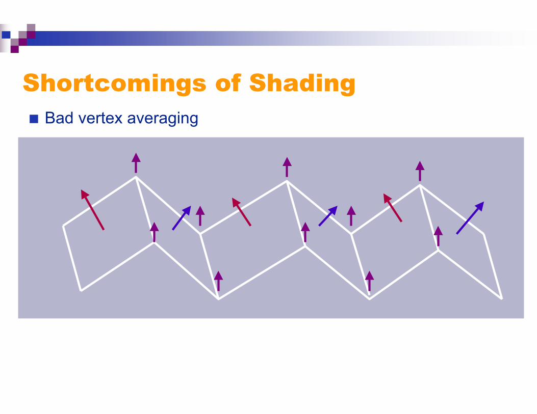
Shortcomings of Shading Bad vertex averaging
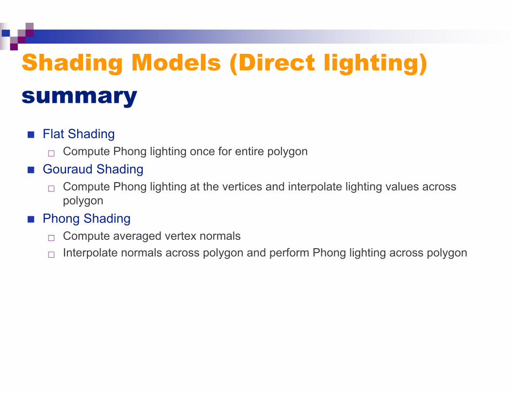
Shading Models (Direct lighting)summary
Flat Shading Compute Phong lighting once for entire polygon
Gouraud Shading Compute Phong lighting at the vertices and interpolate lighting values across
polygon
Phong Shading Compute averaged vertex normals
Interpolate normals across polygon and perform Phong lighting across polygon
Current Generation of Shaders
Current hardware allows you to break from the standardillumination model
Programmable Vertex Shaders allow you to write a smallprogram that determines how the color of a vertex is computed Your program has access to the surface normal and position, plus
anything else you care to give it (like the light)
You can add, subtract, take dot products, and so on
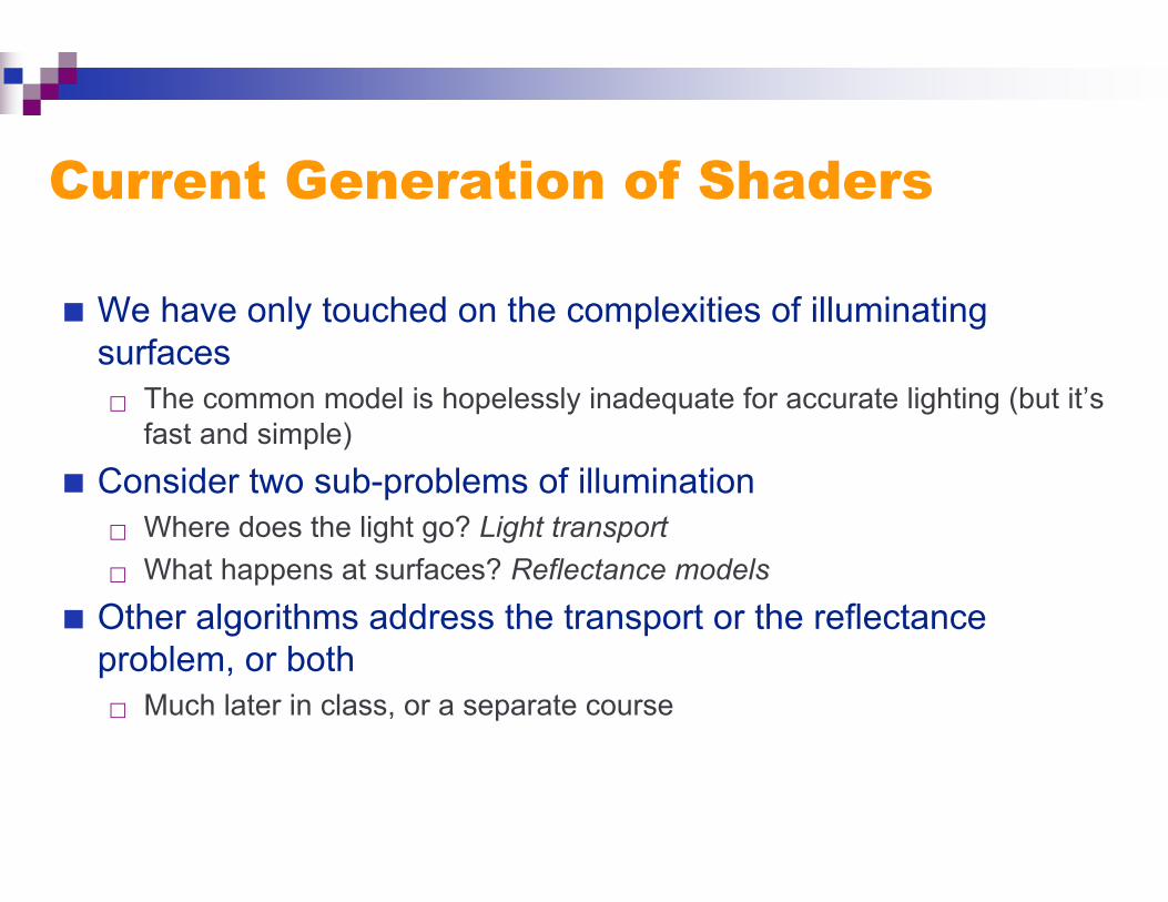
Current Generation of Shaders
We have only touched on the complexities of illuminatingsurfaces The common model is hopelessly inadequate for accurate lighting (but it’s
fast and simple)
Consider two sub-problems of illumination Where does the light go? Light transport
What happens at surfaces? Reflectance models
Other algorithms address the transport or the reflectanceproblem, or both Much later in class, or a separate course
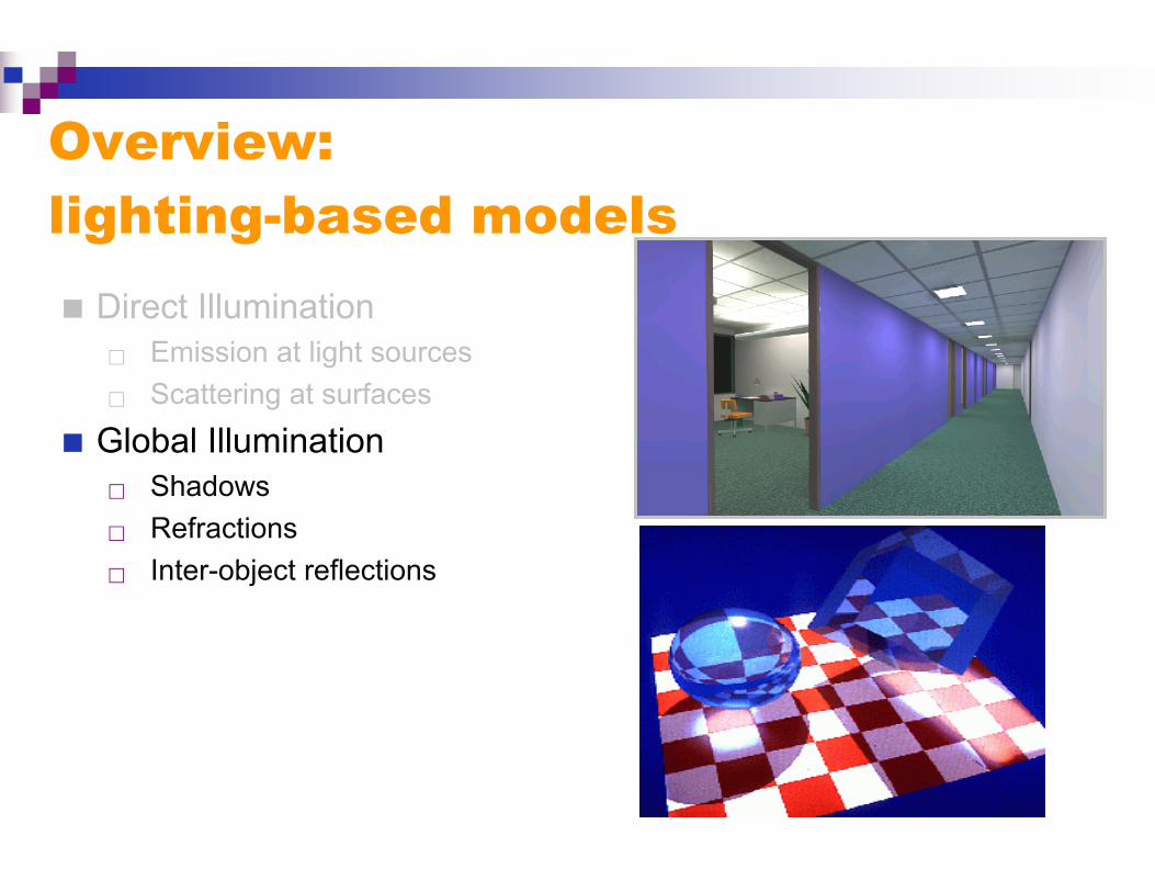
Overview:lighting-based models
Direct Illumination Emission at light sources
Scattering at surfaces
Global Illumination Shadows
Refractions
Inter-object reflections
Global Illumination
Global Illumination
We’ve glossed over how light really works
And we will continue to do so…
One step better
Global Illumination The notion that a point is illuminated by more than light from local
lights; it is illuminated by all the emitters and reflectors in the globalscene
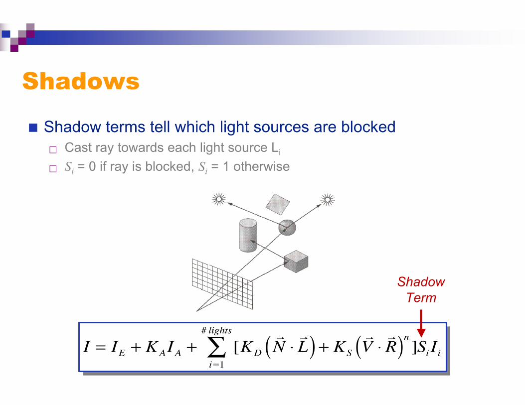
Shadows
Shadow terms tell which light sources are blocked Cast ray towards each light source Li
Si = 0 if ray is blocked, Si = 1 otherwise
I = IE + KAIA + [KD
N ⋅L( ) + KS
V ⋅R( )n ]Si Ii
i=1
# lights
∑
ShadowTerm
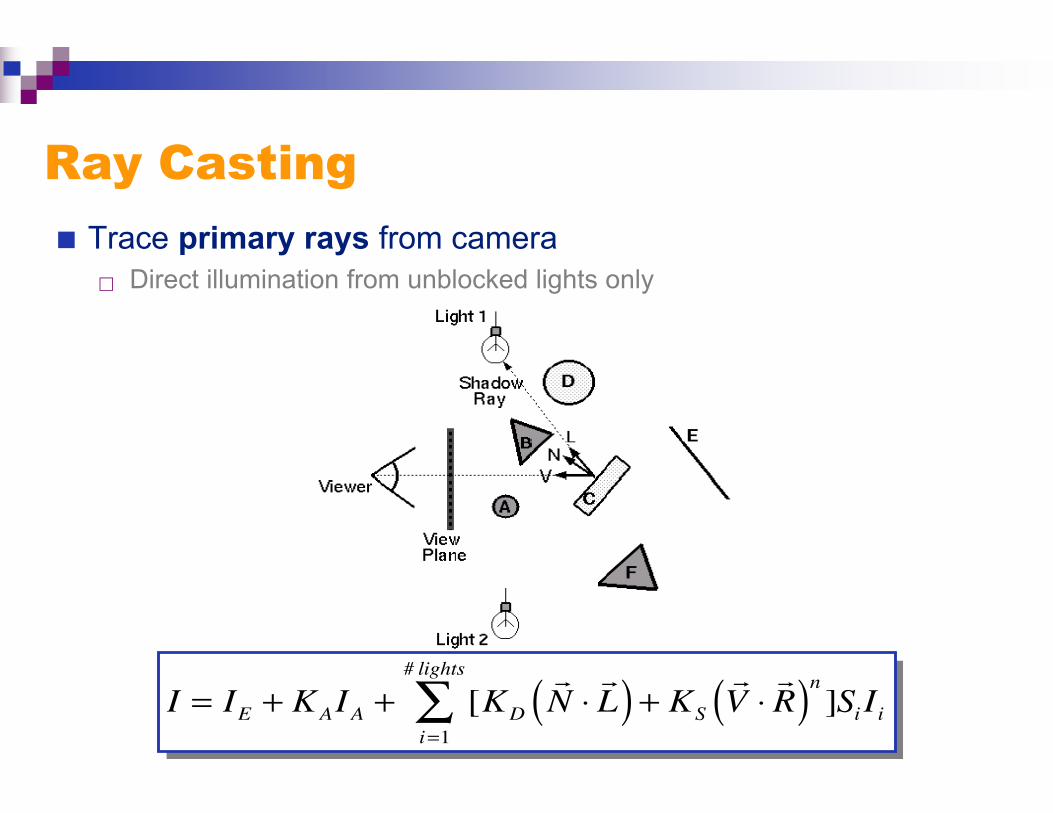
Ray Casting
Trace primary rays from camera Direct illumination from unblocked lights only
I = IE + KAIA + [KD
N ⋅L( ) + KS
V ⋅R( )n ]Si Ii
i=1
# lights
∑
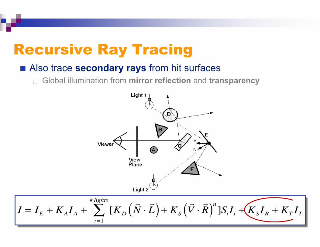
Recursive Ray Tracing Also trace secondary rays from hit surfaces
Global illumination from mirror reflection and transparency
I = IE + KAIA + [KD
N ⋅L( ) + KS
V ⋅R( )n ]Si Ii
i=1
# lights
∑ + KSIR + KT IT
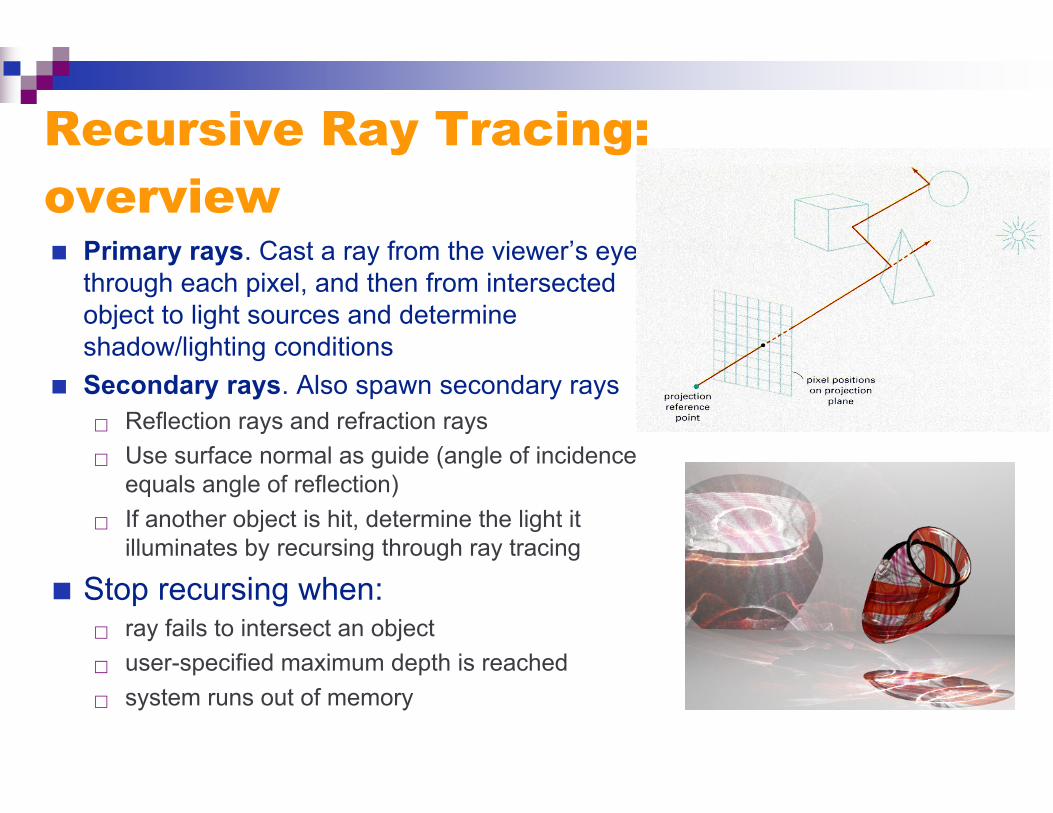
Recursive Ray Tracing:overview Primary rays. Cast a ray from the viewer’s eye
through each pixel, and then from intersectedobject to light sources and determineshadow/lighting conditions
Secondary rays. Also spawn secondary rays Reflection rays and refraction rays
Use surface normal as guide (angle of incidenceequals angle of reflection)
If another object is hit, determine the light itilluminates by recursing through ray tracing
Stop recursing when: ray fails to intersect an object
user-specified maximum depth is reached
system runs out of memory
Recursive Ray Tracing
Stop recursing when: ray fails to intersect an object
user-specified maximum depth is reached
system runs out of memory
Common numerical accuracy error Spawn secondary ray from intersection point
Secondary ray intersects another polygon on same object
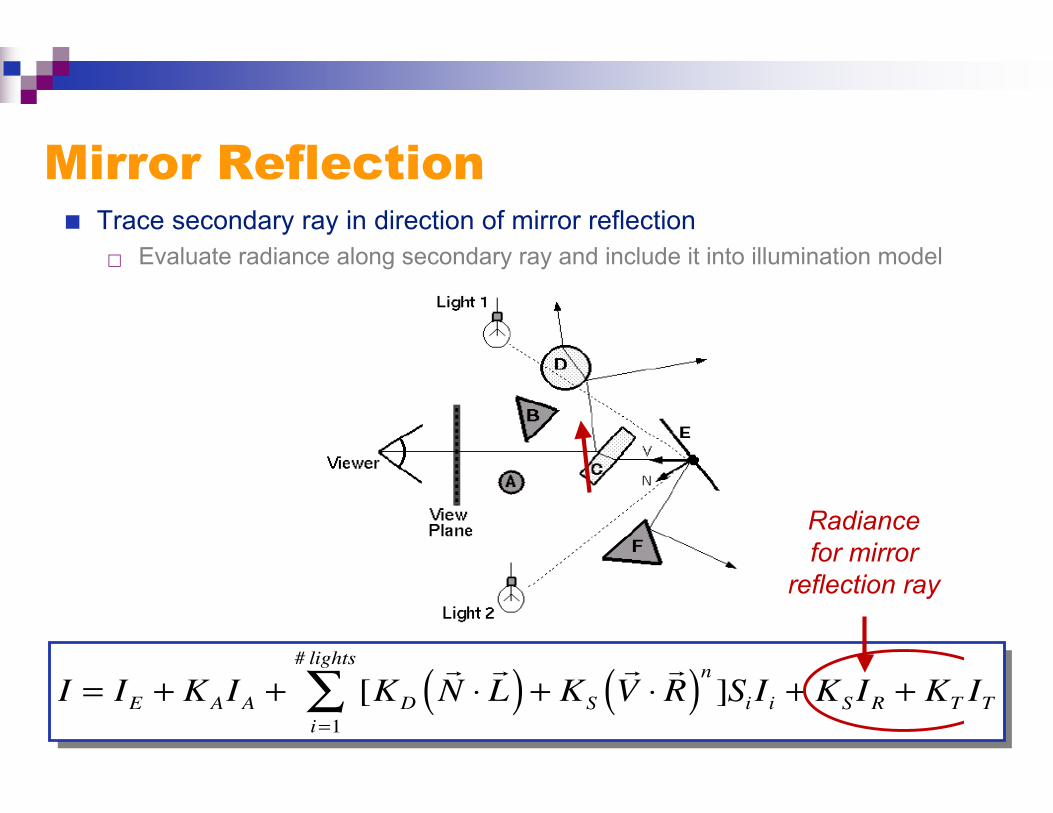
Mirror Reflection Trace secondary ray in direction of mirror reflection
Evaluate radiance along secondary ray and include it into illumination model
I = IE + KAIA + [KD
N ⋅L( ) + KS
V ⋅R( )n ]Si Ii
i=1
# lights
∑ + KSIR + KT IT
Radiancefor mirror
reflection ray

Transparency Trace secondary ray in direction of refraction
Evaluate radiance along secondary ray and include it into illumination model
I = IE + KAIA + [KD
N ⋅L( ) + KS
V ⋅R( )n ]Si Ii
i=1
# lights
∑ + KSIR + KT IT
Radiance forrefraction ray

Transparency Transparency coefficient is fraction transmitted
KT = 1 if object is translucent, KT = 0 if object is opaque
0 < KT < 1 if object is semi-translucent
I = IE + KAIA + [KD
N ⋅L( ) + KS
V ⋅R( )n ]Si Ii
i=1
# lights
∑ + KSIR + KT IT
TransparencyCoefficient
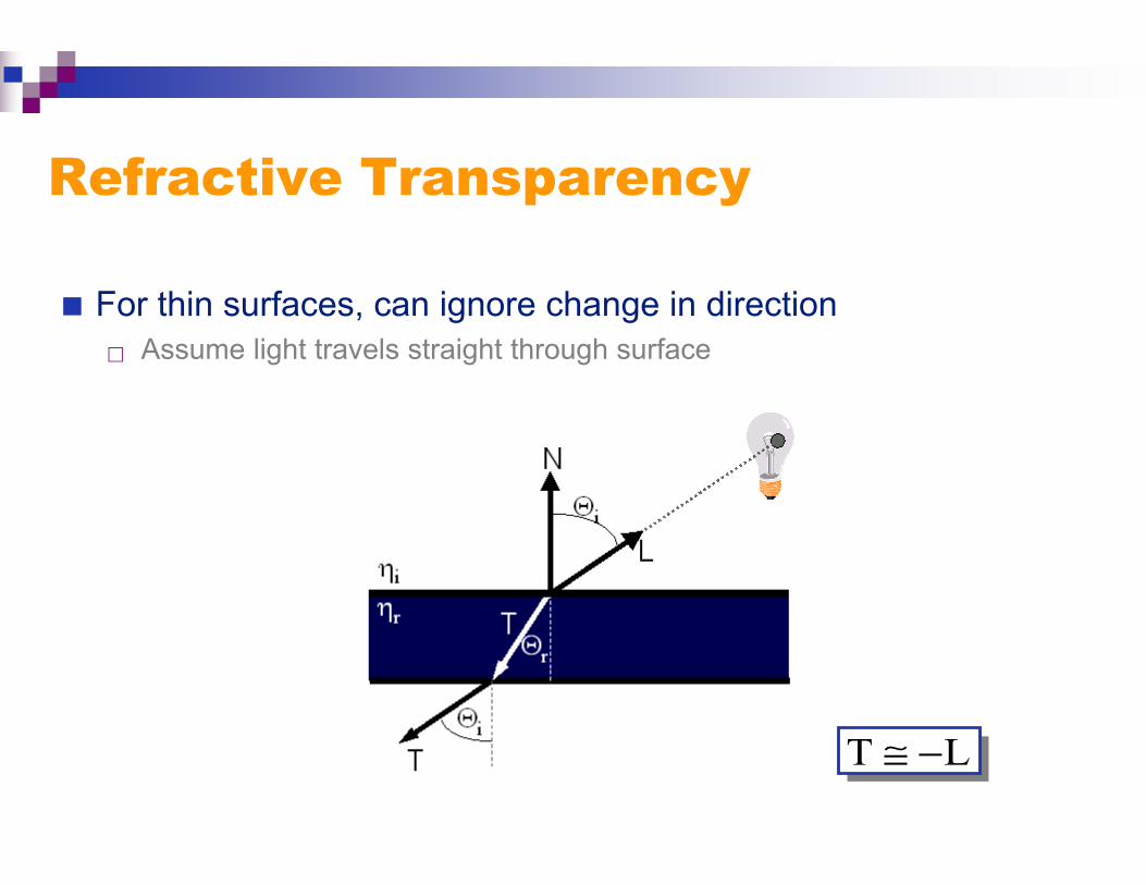
Refractive Transparency
For thin surfaces, can ignore change in direction Assume light travels straight through surface
LT −≅
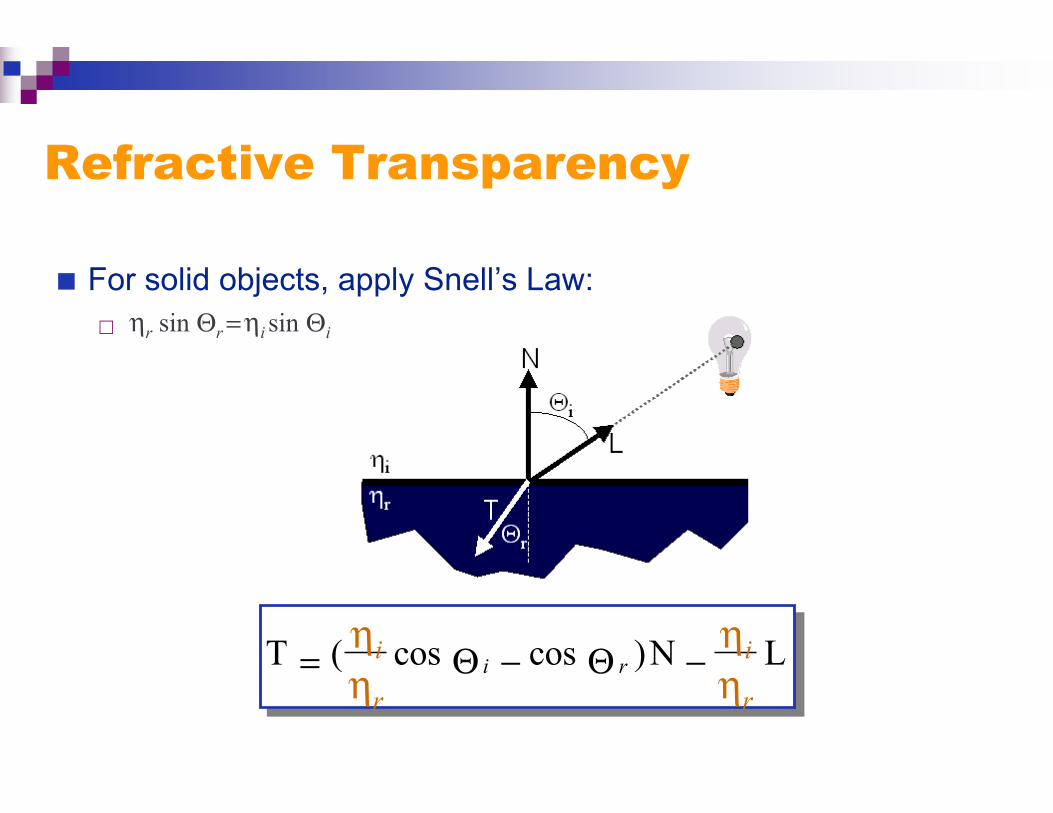
Refractive Transparency
For solid objects, apply Snell’s Law: ηr sin Θr = ηi sin Θi
Lηr
ηiN)coscosηr
ηi(T ri −Θ−Θ=

Radiosity
Ray tracing models specularreflection and refractive transparency, but still uses anambient term to account for other lighting effects
Radiosity is the rate at which energy is emitted or reflectedby a surface
By conserving light energy in a volume,these radiosity effects can be traced
Summary
Direct Illumination-based Shading Ray casting
− Usually use simple analytic approximations for light source emission and surfacereflectance
Indirect illumination-based Shading Recursive ray tracing
− Incorporate shadows, mirror reflections, and pure refractions
Radiosity− Use energy conservative law.
FIM