Embed Size (px)
Citation preview
Extinction-based Shading and Illuminationin GPU Volume Ray-Casting
Philipp Schlegel, Maxim Makhinya, and Renato Pajarola, Member, IEEE
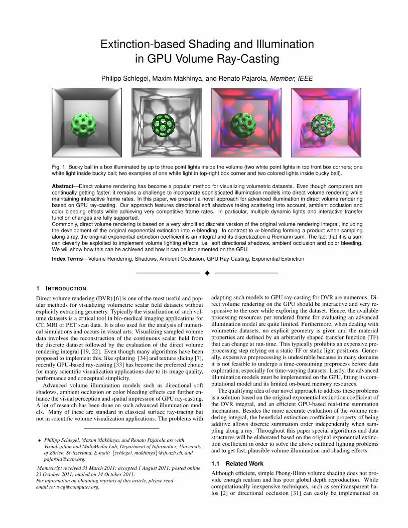
Fig. 1. Bucky ball in a box illuminated by up to three point lights inside the volume (two white point lights in top front box corners; onewhite light inside bucky ball; two examples of one white light in top-right box corner and two colored lights inside bucky ball).
Abstract—Direct volume rendering has become a popular method for visualizing volumetric datasets. Even though computers arecontinually getting faster, it remains a challenge to incorporate sophisticated illumination models into direct volume rendering whilemaintaining interactive frame rates. In this paper, we present a novel approach for advanced illumination in direct volume renderingbased on GPU ray-casting. Our approach features directional soft shadows taking scattering into account, ambient occlusion andcolor bleeding effects while achieving very competitive frame rates. In particular, multiple dynamic lights and interactive transferfunction changes are fully supported.Commonly, direct volume rendering is based on a very simplified discrete version of the original volume rendering integral, includingthe development of the original exponential extinction into α-blending. In contrast to α-blending forming a product when samplingalong a ray, the original exponential extinction coefficient is an integral and its discretization a Riemann sum. The fact that it is a sumcan cleverly be exploited to implement volume lighting effects, i.e. soft directional shadows, ambient occlusion and color bleeding.We will show how this can be achieved and how it can be implemented on the GPU.
Index Terms—Volume Rendering, Shadows, Ambient Occlusion, GPU Ray-Casting, Exponential Extinction
1 INTRODUCTION
Direct volume rendering (DVR) [6] is one of the most useful and pop-ular methods for visualizing volumetric scalar field datasets withoutexplicitly extracting geometry. Typically the visualization of such vol-ume datasets is a critical tool in bio-medical imaging applications forCT, MRI or PET scan data. It is also used for the analysis of numeri-cal simulations and occurs in visual arts. Visualizing sampled volumedata involves the reconstruction of the continuous scalar field fromthe discrete dataset followed by the evaluation of the direct volumerendering integral [19, 22]. Even though many algorithms have beenproposed to implement this, like splatting [34] and texture slicing [7],recently GPU-based ray-casting [33] has become the preferred choicefor many scientific visualization applications due to its image quality,performance and conceptual simplicity.
Advanced volume illumination models such as directional softshadows, ambient occlusion or color bleeding effects can further en-hance the visual perception and spatial impression of GPU ray-casting.A lot of research has been done on such advanced illumination mod-els. Many of these are standard in classical surface ray-tracing butnot in scientific volume visualization applications. The problems with
• Philipp Schlegel, Maxim Makhinya, and Renato Pajarola are withVisualization and MultiMedia Lab, Department of Informatics, Universityof Zurich, Switzerland, E-mail: schlegel, [email protected], [email protected].
Manuscript received 31 March 2011; accepted 1 August 2011; posted online23 October 2011; mailed on 14 October 2011.For information on obtaining reprints of this article, please sendemail to: [email protected].
adapting such models to GPU ray-casting for DVR are numerous. Di-rect volume rendering on the GPU should be interactive and very re-sponsive to the user while exploring the dataset. Hence, the availableprocessing resources per rendered frame for evaluating an advancedillumination model are quite limited. Furthermore, when dealing withvolumetric datasets, no explicit geometry is given and the materialproperties are defined by an arbitrarily shaped transfer function (TF)that can change at run-time. This typically prohibits an expensive pre-processing step relying on a static TF or static light positions. Gener-ally, expensive preprocessing is undesirable because in many domainsit is not feasible to undergo a time-consuming preprocess before dataexploration, especially for time-varying datasets. Lastly, the advancedillumination models must be implemented on the GPU, fitting its com-putational model and its limited on-board memory resources.
The qualifying idea of our novel approach to address these problemsis a solution based on the original exponential extinction coefficient ofthe DVR integral, and an efficient GPU-based real-time summationmechanism. Besides the more accurate evaluation of the volume ren-dering integral, the beneficial extinction coefficient property of beingadditive allows discrete summation order independently when sam-pling along a ray. Throughout this paper special algorithms and datastructures will be elaborated based on the original exponential extinc-tion coefficient in order to solve the above outlined lighting problemsand to get fast, plausible volume illumination and shading effects.
1.1 Related Work
Although efficient, simple Phong-Blinn volume shading does not pro-vide enough realism and has poor global depth reproduction. Whilecomputationally inexpensive techniques, such as semitransparent ha-los [2] or directional occlusion [31] can easily be implemented on
GPUs to improve depth perception, more advanced lighting modelsare still a challenge. Soft shadows, ambient occlusion, light scatteringand color bleeding are desired features in GPU volume rendering [9].
Soft directional shadows that are able to incorporate infinite lightsources only, requiring an additional shadow volume, which is updatedon each light position change, were proposed by Behrens and Rater-ing [1]. Classical shadow mapping [35] can also be applied to volumerendering in limited scenarios to obtain hard shadows. To improveperformance for semitransparent objects, deep-shadow maps [26] usemultiple opacity layers. Shadow maps are dependent on light positionand TF with the evaluation typically done for a single light only. Half-angle slicing [13, 14, 36] is able to produce more realistic soft shadowswith very small additional storage requirements, but also with the lim-itation of a single directional light source support.
Obscurance and ambient occlusion (AO) methods [21, 17] provide asimple way to approximate indirect global illumination by sampling alimited neighborhood. Screen-space AO (SSAO) is popular in polygo-nal shading [32] as well as in volume rendering [4] due to its simplicityand high performance. These methods rely on the visible pixels’ depthvalue estimates, are fast and have sufficient quality for opaque objectsand simple geometry. SSAO can, however, fail in complex scenariosdue to the limited 2D depth information available; they are also ineffi-cient in the case of semitransparent objects when only one depth valueper pixel can be used. These limitations can, at an increased cost, par-tially be solved through depth-peeling [8], where a limited number ofdepth samples can be used in practice.
Object space AO provides better quality than SSAO, at the price ofextra storage and computation. Typically, an additional 3D texture fordensity values is used, which has to be updated upon TF changes. De-pending on the implementation, TF updates can introduce significantlag, if individual neighboring voxels are sampled as presented by Ruizet al. [28], or it can be fast if aggregate values are considered as shownby Diaz et al. [4]. Similar techniques [18, 23] are suitable for polygo-nal rendering; additional 3D textures that represent voxelized objectshave to be created, updated when geometry changes, and sampled dur-ing rendering. Another approach to dynamic AO, based on per-voxellocal histograms, was introduced by Ropinski et al. [27]. TF and lightsource independent illumination are achieved by convolving local his-tograms with the current TF during rendering to obtain an environ-mental color of each voxel. Additional space for histogram clusters ismoderate, and rendering itself is efficient. However, the preprocessingstep requires hours even for medium size models.
Scattering of light requires the inclusion of all indirect light contri-butions. Thus true evaluation is very expensive, yet a clever approx-imation can provide pleasant visual quality at interactive frame rateson modern hardware. Good results were achieved by Kniss et al. [14],where only light contribution within a cone directed towards the lightsource was taken into account at each sample position. This allowedsuperimposing contributions of direct and indirect light in one render-ing pass, using half-angle slicing. No preprocessing is required, butonly a single point light source can be used. This method was furtherexplored by Ropinski et al. [25], resulting in fewer sampling opera-tions for the illumination computation and allowing integration withGPU volume ray-casters. These benefits are achieved at the expenseof recomputing a 3D light volume upon every light position change.
Color bleeding is often integrated with obscurance methods, as itrequires only minor changes to AO [20]. Many AO and translucencymethods gather aggregate color information of the voxels’ neighbor-hood together with the opacity, to use it for color bleeding effects[28, 27, 11]. Similarly, color bleeding can be integrated in light scat-tering techniques as well [14, 25].
1.2 ContributionsOur approach includes a number of contributions and advantages toachieve more realistic and efficient volume illumination. (i) A unifiedapproximate model for both local ambient occlusion and directionalsoft shadows, as well as (homogeneous) light scattering and colorbleeding is presented. (ii) The model is based on the summation of theexponential extinction coefficient, exploiting a 3D summed area table
(SAT) for fast computation. (iii) Directional soft shadows can be com-puted reusing the same SAT as for ambient occlusion, having minimalperformance impact. (iv) The proposed discrete extinction coefficientsummation supports distance weighted ambient occlusion and shadowcontributions. (v) The introduced solution requires no expensive pre-processing and allows for interactive TF changes. (vi) Multiple as wellas dynamic point and spot light sources are supported. Moreover, ar-bitrary light source positions are allowed also inside the actual volumedata. (vii) The model is integrated in a high-quality ray-casting basedvolume visualization application and works in real-time on the GPU.(viii) At run-time, some additional 3D texture storage is required tohold the TF dependent extinction coefficients. This data, however, canbe adjusted flexibly for resolution accuracy and storage overhead.
2 LIGHTING WITH ADDITIVE EXPONENTIAL EXTINCTION
2.1 Additive Exponential Extinction Coefficients
Direct volume rendering is based on the emission and absorption the-orem by Max [19], leading to the DVR integral (Eq. 1). It can beshown [22] that the volume rendering integral cannot be solved analyt-ically without making some confining assumptions, and consequentlyneeds to be approximated. This includes the commonly used develop-ment of the original extinction coefficient into a Taylor series whereonly the first two elements are considered, which is equivalent to clas-sical α-blending [24]. However, this is a rather coarse approxima-tion optimized for mapping to fixed-function 3D graphics hardware ofthe past. Today with fast, programmable GPUs it is not required any-more [15, 30]. A closer approximation based on the original extinctioncoefficient can be chosen for a more accurate evaluation of the volumerendering integral. In addition, the advantage of integrating over theexponential extinction coefficient is that it corresponds to a summa-tion, since being additive, when sampling along a ray, in contrast tothe (ordered) product of α-blending.
In Eq. 1, a ray from s = 0 at the back of the volume to s = D at theeye position is considered. The extinction coefficient is indicated byτ(s), and E(s) is the light reflected or emitted by a volume sample ats. The integrated intensity along a viewing ray is now given by:
I(D) =∫ D
0E(s)τ(s)e−
∫ Ds τ(t)dtds. (1)
In the discretization of Eq. 1 using a step size ∆t along the ray,instead of performing a Taylor series expansion and simplification ofthe extinction term – as done in the past for fixed-function graphicshardware α-blending – the original exponential extinction coefficientcan be retained as
I(D)≈D/∆t
∑i=0
Ei ·∆tτie−∑
D/∆tj=i ∆tτ j , (2)
where the reflected and emitted light Ei is typically replaced by a voxelcolor modulated by a simple lighting model.
The formulation of Eq. 2 is sufficiently simple and can easily beimplemented on programmable GPUs. The additive property of τ al-lows for the summation of the samples in a shader in arbitrary order,followed by an exponential function applied to this sum, which can bedone efficiently on today’s GPUs. Hence the big advantage of Eq. 2is not only an improved image quality compared to the less accurateapproximation using multiplicative α-blending (see also [15, 30]), butalso the fact that any attenuation calculation can be implemented by asummation of extinction coefficients, notably in arbitrary order.
In the following we will show how this summation can efficientlybe exploited for volume shading and illumination purposes. The basicpremise is that any light occlusion and thus shadowing effects arisefrom the attenuation of light traveling or being scattered through thevolume along a ray or within some specific region. Therefore, anylight attenuation stems from some extinction factor e−∑ j ∆tτ j wherethe sum ∑ j ∆tτ j must be taken over a ray or region of the volume.
2.2 Ambient Occlusion and Color Bleeding
Ambient occlusion (AO) is an approximated attenuation of diffuselyreflected ambient light through occlusion. It is not physically accurate,but since full-fledged physical illumination models such as global il-lumination [12] are beyond interactive volume rendering, AO is a veryuseful and effective approximation of the effect [17, 27, 11, 4].
The reflected light term E in the DVR integral includes an ambientterm representing diffusely reflected ambient light. In the AO light-ing model, this term IAO is not a constant but a function taking theocclusion in the local neighborhood of a sample s into account. Itrepresents the total amount of unoccluded incident light over a sphereΩ at s, where I(s,ω ′) denotes the incoming light at position s fromdirection ω ′:
IAO(s) =∫
ω ′∈Ω
I(s,ω ′)dω′. (3)
Instead of densely sampling the sphere Ω and tracing many shadowrays for I(s,ω ′), as shown by Ruiz [28] and Hernell [11] respectively,we opt for a much faster approximation. Only a well-defined localneighborhood N(s) of s is considered for local ambient occlusion. Weassume that for all samples s a constant ambient light intensity IA isincident over the boundary ∂N(s). IA is proportional to the sum of alllights, expressed by an ambient light term coefficient. Hence only thelocal light attenuation inside the neighborhood N(s) has to be consid-ered. The local ambient occlusion is thus modeled by the distributionof the extinction τ in the neighborhood N(s) as
IAO(s)≈ IA · e−∫
t∈N(s)τ(t)|s−t|2
dt, (4)
where the inverse of the square distance accounts for the law of radialdistance based light attenuation.
Color bleeding describes the phenomenon that the color appearanceof a surface is locally affected by colored nearby objects [20]. As thisillumination effect is also primarily based on the local neighborhoodof a sample point, it can be approximated in a similar way to ambientocclusion. For AO only the extinction coefficient has been taken intoaccount as an indicator for opacity at a particular position within thevolume. For the estimation of color bleeding, the color also has to betaken into account as an additional parameter CRGB depending on theTF. So Eq. 4 can be reformulated to
IAORGB(s)≈ IA · e−∫
t∈N(s)τ(t)CRGB(t)
|s−t|2dt
, (5)
where IAORGB is a vector describing the intensity per color.Since the summation of the exponential extinction coefficients in
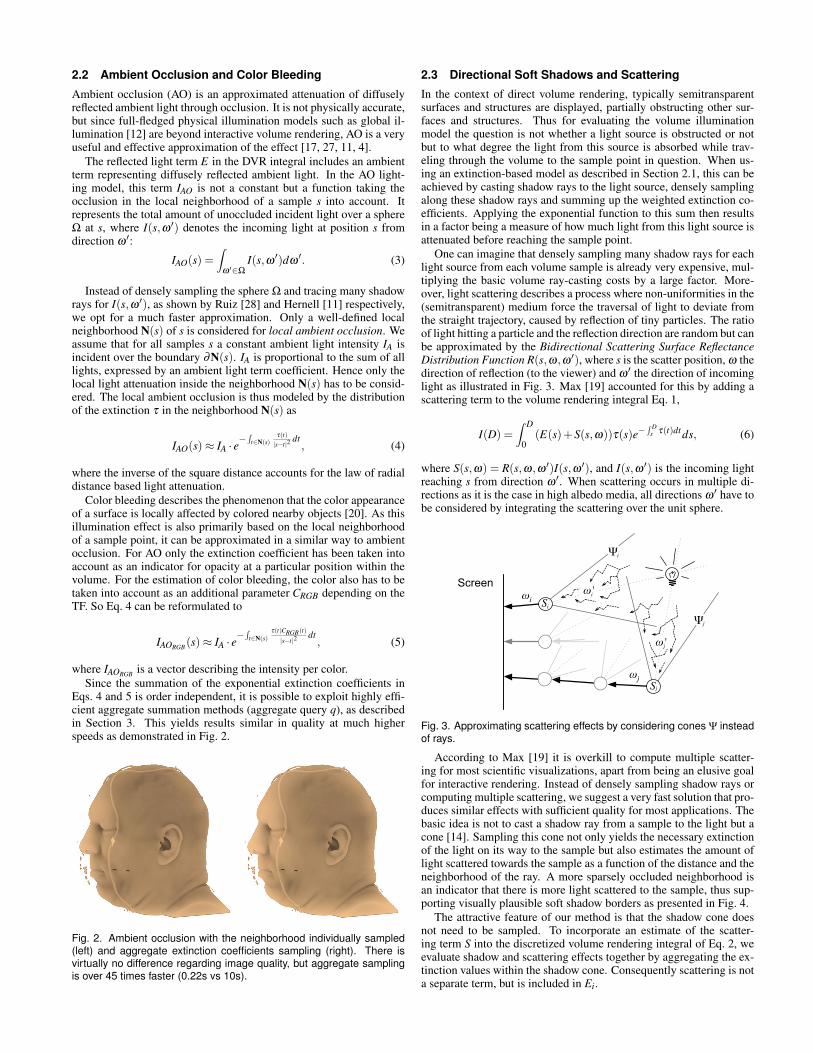
Eqs. 4 and 5 is order independent, it is possible to exploit highly effi-cient aggregate summation methods (aggregate query q), as describedin Section 3. This yields results similar in quality at much higherspeeds as demonstrated in Fig. 2.
Fig. 2. Ambient occlusion with the neighborhood individually sampled(left) and aggregate extinction coefficients sampling (right). There isvirtually no difference regarding image quality, but aggregate samplingis over 45 times faster (0.22s vs 10s).
2.3 Directional Soft Shadows and Scattering
In the context of direct volume rendering, typically semitransparentsurfaces and structures are displayed, partially obstructing other sur-faces and structures. Thus for evaluating the volume illuminationmodel the question is not whether a light source is obstructed or notbut to what degree the light from this source is absorbed while trav-eling through the volume to the sample point in question. When us-ing an extinction-based model as described in Section 2.1, this can beachieved by casting shadow rays to the light source, densely samplingalong these shadow rays and summing up the weighted extinction co-efficients. Applying the exponential function to this sum then resultsin a factor being a measure of how much light from this light source isattenuated before reaching the sample point.
One can imagine that densely sampling many shadow rays for eachlight source from each volume sample is already very expensive, mul-tiplying the basic volume ray-casting costs by a large factor. More-over, light scattering describes a process where non-uniformities in the(semitransparent) medium force the traversal of light to deviate fromthe straight trajectory, caused by reflection of tiny particles. The ratioof light hitting a particle and the reflection direction are random but canbe approximated by the Bidirectional Scattering Surface ReflectanceDistribution Function R(s,ω,ω ′), where s is the scatter position, ω thedirection of reflection (to the viewer) and ω ′ the direction of incominglight as illustrated in Fig. 3. Max [19] accounted for this by adding ascattering term to the volume rendering integral Eq. 1,
I(D) =∫ D
0(E(s)+S(s,ω))τ(s)e−
∫ Ds τ(t)dtds, (6)
where S(s,ω) = R(s,ω,ω ′)I(s,ω ′), and I(s,ω ′) is the incoming lightreaching s from direction ω ′. When scattering occurs in multiple di-rections as it is the case in high albedo media, all directions ω ′ have tobe considered by integrating the scattering over the unit sphere.
Screenωi
ωjS
S
ωj'
ωi'
Ψ
Ψ
j
i
i
j
Fig. 3. Approximating scattering effects by considering cones Ψ insteadof rays.
According to Max [19] it is overkill to compute multiple scatter-ing for most scientific visualizations, apart from being an elusive goalfor interactive rendering. Instead of densely sampling shadow rays orcomputing multiple scattering, we suggest a very fast solution that pro-duces similar effects with sufficient quality for most applications. Thebasic idea is not to cast a shadow ray from a sample to the light but acone [14]. Sampling this cone not only yields the necessary extinctionof the light on its way to the sample but also estimates the amount oflight scattered towards the sample as a function of the distance and theneighborhood of the ray. A more sparsely occluded neighborhood isan indicator that there is more light scattered to the sample, thus sup-porting visually plausible soft shadow borders as presented in Fig. 4.
The attractive feature of our method is that the shadow cone doesnot need to be sampled. To incorporate an estimate of the scatter-ing term S into the discretized volume rendering integral of Eq. 2, weevaluate shadow and scattering effects together by aggregating the ex-tinction values within the shadow cone. Consequently scattering is nota separate term, but is included in Ei.
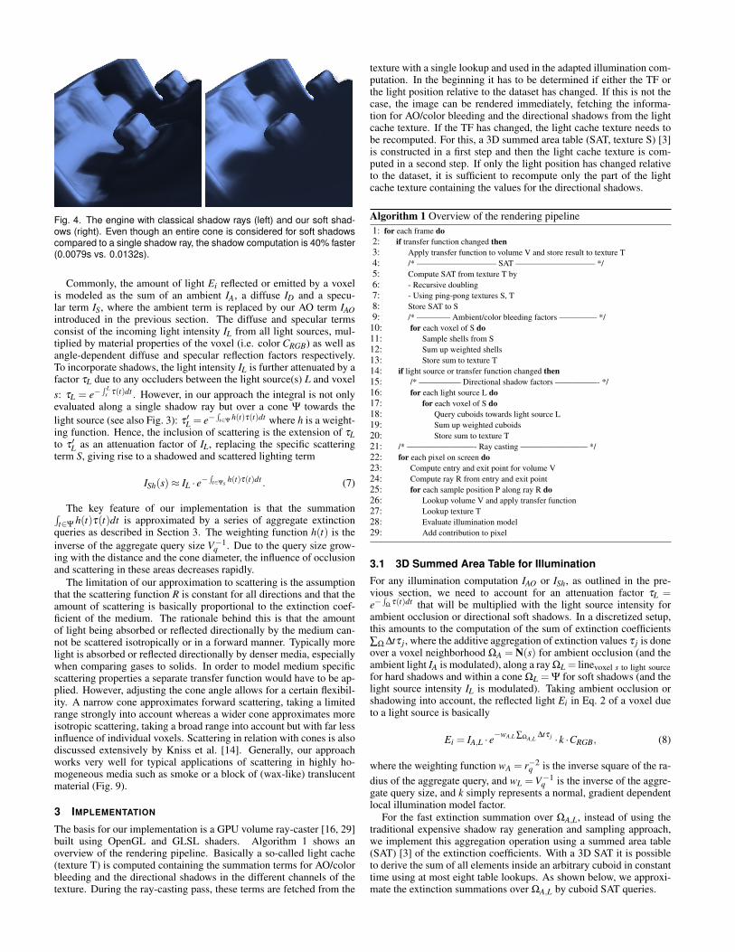
Fig. 4. The engine with classical shadow rays (left) and our soft shad-ows (right). Even though an entire cone is considered for soft shadowscompared to a single shadow ray, the shadow computation is 40% faster(0.0079s vs. 0.0132s).
Commonly, the amount of light Ei reflected or emitted by a voxelis modeled as the sum of an ambient IA, a diffuse ID and a specu-lar term IS, where the ambient term is replaced by our AO term IAOintroduced in the previous section. The diffuse and specular termsconsist of the incoming light intensity IL from all light sources, mul-tiplied by material properties of the voxel (i.e. color CRGB) as well asangle-dependent diffuse and specular reflection factors respectively.To incorporate shadows, the light intensity IL is further attenuated by afactor τL due to any occluders between the light source(s) L and voxels: τL = e−
∫ Ls τ(t)dt . However, in our approach the integral is not only
evaluated along a single shadow ray but over a cone Ψ towards thelight source (see also Fig. 3): τ ′L = e−
∫t∈Ψ
h(t)τ(t)dt where h is a weight-ing function. Hence, the inclusion of scattering is the extension of τLto τ ′L as an attenuation factor of IL, replacing the specific scatteringterm S, giving rise to a shadowed and scattered lighting term
ISh(s)≈ IL · e−∫
t∈Ψs h(t)τ(t)dt . (7)
The key feature of our implementation is that the summation∫t∈Ψ
h(t)τ(t)dt is approximated by a series of aggregate extinctionqueries as described in Section 3. The weighting function h(t) is theinverse of the aggregate query size V−1
q . Due to the query size grow-ing with the distance and the cone diameter, the influence of occlusionand scattering in these areas decreases rapidly.
The limitation of our approximation to scattering is the assumptionthat the scattering function R is constant for all directions and that theamount of scattering is basically proportional to the extinction coef-ficient of the medium. The rationale behind this is that the amountof light being absorbed or reflected directionally by the medium can-not be scattered isotropically or in a forward manner. Typically morelight is absorbed or reflected directionally by denser media, especiallywhen comparing gases to solids. In order to model medium specificscattering properties a separate transfer function would have to be ap-plied. However, adjusting the cone angle allows for a certain flexibil-ity. A narrow cone approximates forward scattering, taking a limitedrange strongly into account whereas a wider cone approximates moreisotropic scattering, taking a broad range into account but with far lessinfluence of individual voxels. Scattering in relation with cones is alsodiscussed extensively by Kniss et al. [14]. Generally, our approachworks very well for typical applications of scattering in highly ho-mogeneous media such as smoke or a block of (wax-like) translucentmaterial (Fig. 9).
3 IMPLEMENTATION
The basis for our implementation is a GPU volume ray-caster [16, 29]built using OpenGL and GLSL shaders. Algorithm 1 shows anoverview of the rendering pipeline. Basically a so-called light cache(texture T) is computed containing the summation terms for AO/colorbleeding and the directional shadows in the different channels of thetexture. During the ray-casting pass, these terms are fetched from the
texture with a single lookup and used in the adapted illumination com-putation. In the beginning it has to be determined if either the TF orthe light position relative to the dataset has changed. If this is not thecase, the image can be rendered immediately, fetching the informa-tion for AO/color bleeding and the directional shadows from the lightcache texture. If the TF has changed, the light cache texture needs tobe recomputed. For this, a 3D summed area table (SAT, texture S) [3]is constructed in a first step and then the light cache texture is com-puted in a second step. If only the light position has changed relativeto the dataset, it is sufficient to recompute only the part of the lightcache texture containing the values for the directional shadows.
Algorithm 1 Overview of the rendering pipeline1: for each frame do2: if transfer function changed then3: Apply transfer function to volume V and store result to texture T4: /* —————————– SAT —————————– */5: Compute SAT from texture T by6: - Recursive doubling7: - Using ping-pong textures S, T8: Store SAT to S9: /* ———— Ambient/color bleeding factors ————– */
10: for each voxel of S do11: Sample shells from S12: Sum up weighted shells13: Store sum to texture T14: if light source or transfer function changed then15: /* ————— Directional shadow factors —————- */16: for each light source L do17: for each voxel of S do18: Query cuboids towards light source L19: Sum up weighted cuboids20: Store sum to texture T21: /* ————————- Ray casting ———————— */22: for each pixel on screen do23: Compute entry and exit point for volume V24: Compute ray R from entry and exit point25: for each sample position P along ray R do26: Lookup volume V and apply transfer function27: Lookup texture T28: Evaluate illumination model29: Add contribution to pixel
3.1 3D Summed Area Table for IlluminationFor any illumination computation IAO or ISh, as outlined in the pre-vious section, we need to account for an attenuation factor τL =e−
∫Ω
τ(t)dt that will be multiplied with the light source intensity forambient occlusion or directional soft shadows. In a discretized setup,this amounts to the computation of the sum of extinction coefficients∑Ω ∆tτ j, where the additive aggregation of extinction values τ j is doneover a voxel neighborhood ΩA = N(s) for ambient occlusion (and theambient light IA is modulated), along a ray ΩL = linevoxel s to light sourcefor hard shadows and within a cone ΩL = Ψ for soft shadows (and thelight source intensity IL is modulated). Taking ambient occlusion orshadowing into account, the reflected light Ei in Eq. 2 of a voxel dueto a light source is basically
Ei = IA,L · e−wA,L ∑ΩA,L
∆tτ j · k ·CRGB, (8)
where the weighting function wA = r−2q is the inverse square of the ra-
dius of the aggregate query, and wL = V−1q is the inverse of the aggre-
gate query size, and k simply represents a normal, gradient dependentlocal illumination model factor.
For the fast extinction summation over ΩA,L, instead of using thetraditional expensive shadow ray generation and sampling approach,we implement this aggregation operation using a summed area table(SAT) [3] of the extinction coefficients. With a 3D SAT it is possibleto derive the sum of all elements inside an arbitrary cuboid in constanttime using at most eight table lookups. As shown below, we approxi-mate the extinction summations over ΩA,L by cuboid SAT queries.
Since the extinction coefficients are transfer function (TF) depen-dent, this SAT needs to be updated whenever the TF changes. How-ever, fast SAT construction on the GPU [10, 4] can be implementedbased on the recursive doubling technique [5] using a logarithmicnumber of passes, allowing interactive TF changes as demonstratedin Section 4. We use a render-to-3D texture approach which allowsfor a number of implementation synergies and avoids OpenGL-CUDAswitches. Unlike Diaz et al. [4] we are not using opacity values for theSAT but extinction coefficients.
In order to compute our illumination model two auxiliary 3D tex-tures are used, one for the SAT, and another as a ping-pong texture dur-ing SAT generation becoming a light cache during rendering. Thesetwo textures can be of arbitrary size within the OpenGL limitations,depending on the desired quality/performance, and do not necessarilyneed to match the input volume resolution, see also Fig. 11. Algo-rithm 1 shows an overview of the rendering steps.
3.2 Ambient Occlusion and Color Bleeding
Remarkably, for approximating IAO(s) according to Eq. 4, the extinc-tion coefficient SAT can be effectively used. The discretized extinctioncoefficient summation ∑ΩA
∆tτ j in Eq. 8 is approximated by a series ofcuboid shells as indicated in Fig. 5, where the number and size of theshells can be varied. Hence, ΩA is a set of cuboids Shi. For each shell,its aggregate sum of extinction coefficients can be obtained quickly bySAT lookups. A larger set of shells with varying diameters leads toa better image quality but requires more SAT lookups increasing thecosts. According to our experiments as few as three shells are suffi-cient to reach an image quality hardly distinguishable from individu-ally sampling a large neighborhood, as demonstrated in Fig. 2. Only ifthe radius of ΩA exceeds 10% of the radius of the entire dataset, moreshells may become necessary. The use of cuboid shells is entirely dif-ferent from Diaz’ approach [4], where the neighborhood is subdividedinto eight adjacent octants preventing a distance based weighting.
Samplerays
Shells
Shi+2
ShiShi+1
Fig. 5. Ambient occlusion computation by way of sampling the sphericalneighborhood (left) versus SAT-based lookups (right). Compared to per-voxel sampling, the number of 3D texture fetches is a order of magnitudesmaller using the SAT method.
For AO/color bleeding, multiple shells are queried and accumu-lated as indicated in Fig. 5. First, the innermost shell Sh0 is queriedfrom the SAT and weighted by the inverse square of its radius,τSh0 = SAT (Sh0) ·
∣∣rSh0
∣∣−2. Iteratively all shells are accumulated by
τShi+1 = τShi +(SAT (Shi+1)−SAT (Shi)) ·∣∣rShi+1
∣∣−2 until the last shellis processed. The result of this summation is stored in the auxiliary3D light cache texture.
Ambient occlusion is independent of the light position, but needs tobe recomputed if the TF changes. The actual values for AO are cachedtogether with the values from the directional shadows in the 3D lightcache texture. Consequently ambient occlusion in our solution comesat zero cost during rendering.
Of course Eq. 5 for color bleeding can be computed similar to Eq. 4using a SAT that stores vectors τCRGB. Since four values can be pro-cessed per operation with OpenGL textures, the SAT for τCRGB canbe constructed at the same time with the SAT for τ , and stored in the
same 3D texture at no additional computation costs. The only down-sides are the additional memory and memory bandwidth requirementscompared to a single channel texture that would be used when con-structing the SAT for τ only. However, on our hardware the additionalmemory bandwidth requirements do not harm rendering performance.The typical number of shells required for color bleeding proved to bethe same as for AO. An example of color bleeding is shown in Fig. 6.
Fig. 6. The Cornell box with soft shadows and strong ambient occlusion(left), as well as color bleeding (right). Due to the fixed light sourceof the Cornell box, rendering with soft shadows and AO/color bleedingenabled comes at near zero extra cost (one additional texture lookup).
3.3 Directional Soft Shadows and ScatteringFor the directional soft shadow illumination ISh(s) according to Eq. 7,two cases have to be differentiated. If the light sources are at a fixedposition with respect to the dataset, as it is the case with the Cor-nell box model, the attenuation factors for directional soft shadowsonly have to be computed once and are stored in the auxiliary lightcache together with the terms for ambient occlusion/color bleeding.In this case, the total cost for evaluating our extinction-based illumi-nation model during rendering consists of a single, additional texturelookup per sample having only a minor impact on the overall perfor-mance. If the light sources change their relative position with respectto the dataset when rotating, moving and zooming, then the occlusionfactors have to be queried from the extinction SAT for every frame.
Light cone Ψ
Light coneprojection
Primaryaxis
Approximatedcuboid'sprojection
Secondaryaxis
Secondaryaxis
Approximationthreshold
Samplingpoints
Fig. 7. The cone is approximated by a series of cuboids. The mainaxis is determined and the cone is projected onto the planes with thesecondary axes. The intersections of the projections with lines parallelto the secondary axes through the sample points on the main axis definethe cuboids.
When needed, the attenuation factors for directional soft shadows,given by the discrete extinction coefficient summation ∑ΩL
∆tτ j inEq. 8 over the sampling cone ΩL = Ψ, are computed by a render-to-3D-texture pass with the appropriate shader enabled. This shaderapproximates the attenuation cone Ψ for each voxel and light source
Dataset Volume SAT Shells Cone Cone Lights With Without FigureSize Size Samples Angle [Dynamic / Static] Illumination Illumination
Head 128 x 256 x 256 1923 15 n/a n/a ambient only 111fps 143fps 2Engine 256 x 256 x 128 643 n/a 50 10 1 / 0 57fps 130fps 4
Cornell box 256 x 256 x 256 2563 5 60 16 0 / 1 133fps 161fps 6Pelvis 512 x 512 x 461 643 5 50 2 2 / 0 15fps 26fps 8Feet 512 x 512 x 250 1283 3 50 2 1 / 0 13fps 31fps 8
Bucky ball 128 x 128 x 128 1283 3 80 2 0 / 1, 2, 3 55fps 62fps 1, 9Skull 128 x 256 x 256 1283 5 50 2 0 / 2 14fps 26fps 9
Pelvis (comparison) 512 x 512 x 461 1923 3 40 1, 3, 5 1 / 0 3fps 30fps 10Engine (comparison) 256 x 256 x 128 643, 1283 5 40 2 1 / 0 26fps, 12fps 49fps 11Engine (comparison) 256 x 256 x 128 1923, 2563 5 40 2 1 / 0 5fps, 3fps 49fps 11
Table 1. Overall frame rates with and without extinction-based illumination for a 5122 pixel viewport. Except for the head, Cornell box, skull andbucky ball, the directional soft shadows are computed dynamically for every frame.
Fig. 8. Medical datasets rendered with extinction based-shading andillumination including directional soft shadows and ambient occlusion.The left image is rendered using two lights and shows multiple shadows.
by a series of cuboids. The primary cone axis is defined to be the co-ordinate axis with the smallest angle to the vector to the light source.The sampling points on the primary axis are given by a user definedsampling frequency and growth rate. The growth rate (growth of thecuboids) is the change of the frequency over the distance since fur-ther away a smaller sampling frequency may be sufficient. The cuboidqueries are then derived from this primary axis sampling and from theprojection of the query cone onto the primary-secondary axis planes asshown in Fig. 7. Because the SAT inherently allows only axis-alignedlookups, deriving the primary and secondary axes is required. Choos-ing the axes in this way yields the best possible coverage of the conewith cuboids. With the cone covered by cuboids, the summation of theextinction coefficients can quickly be obtained by a few SAT lookups.
The shadow and scattering approximation by extinction SATqueries makes it very fast and flexible. The number of cuboids and thecone angle of Ψ can easily be varied, or the cuboids can be weighteddifferently using h in order to strengthen or weaken the effect. Ap-proximating the cone by exploiting the SAT allows for soft, realisticlooking, directional shadows at very low costs as shown in Fig. 4. Incontrast to the half angle slicing method by Kniss et al. [14] our solu-tion can handle any type and multiple light sources. It is also differentfrom the method by Ropinski et al. [25] because we do not propagateillumination from the outside but compute the extinction of the lightintensity for the voxels. We can therefore trivially handle light sourceseven within or on the border of the dataset without any additional ef-fort. Multiple light sources can also be easily dealt with (see Fig. 1 formultiple point and spot light sources inside the volume).
The angle of the cone Ψ, the number of cuboids for approximation(defined by a sampling frequency), the growth rate, and a weightingfunction are parameters that can be chosen freely according to thedesired quality/performance and strength of the shadow effects (seeFig. 10). Typically a few dozen lookups per cone and voxel are alreadysufficient to approximate the attenuation cone, compared to classicalshadow rays where hundreds of samples are required to achieve a simi-lar quality (see Section 4). Hence, even when computing these shadow
Fig. 9. Bucky ball in a smoky cube where a point light source is insidethe bucky ball and a spot light in the top right corner (left), and Skull inthick fog or a block of translucent material with a point light source in theback scattering light through the medium and a spot light in the top leftcorner (right).
terms for every frame, the performance impact is tolerable with respectto the achieved shading effects. To avoid duplicate shadow queries, thecomputed terms are stored in the light cache texture together with theterms for ambient occlusion/color bleeding.
4 RESULTS
All experiments have been performed on a Mac Pro 2.4GHz dual-Xeon with NVIDIA GeForce GTX 285 graphics.
Compared to a Phong-Blinn-based GPU ray-caster, a ray-casterwith our illumination model can produce realistic looking images withimproved depth and occlusion effects (i.e. Figs. 8, 10, 11). To ensureinteractivity and responsivity, we use a 3D SAT enabling fast approx-imation of shadow cones with cuboids and AO/color bleeding usingcuboid shells. For each change of the TF, the extinction SAT and theAO/color bleeding terms have to be recomputed. Every time the lightsource moves relative to the dataset or the TF changes, the terms forthe directional shadows will be recomputed. During the actual ray-casting pass, one additional texture lookup per sample is sufficient toapply the illumination terms. Other approaches [27] need two addi-tional texture lookups for AO, not considering directional shadows.
Table 1 demonstrates the interactive performance of our extinction-based illumination model. This includes computation of the SAT andthe ambient factors once and the factors for directional shadows inevery frame. The exceptions are the head, Cornell box, skull and buckyball datasets where the factors for the directional shadows have to becomputed only once due to the fixed light source(s).
The time required for constructing the 3D SAT for different sizes is0.029, 0.067, 0.148 and 0.311s for 643, 1283, 1923 and 2563 volumesrespectively. Even though we do not use CUDA, the time is similar tothe one reported by Diaz et al. [4] for the 2563 volume and is in factmuch faster for smaller volume sizes. Moreover, our timings includethe concurrent construction of the 3D SAT comprising the terms for
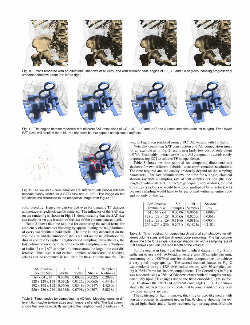
Fig. 10. Pelvis rendered with no directional shadows at all (left), and with different cone angles of 1.0, 3.0 and 5.0 degrees, causing progressivelysmoother shadows (from 2nd left to right).
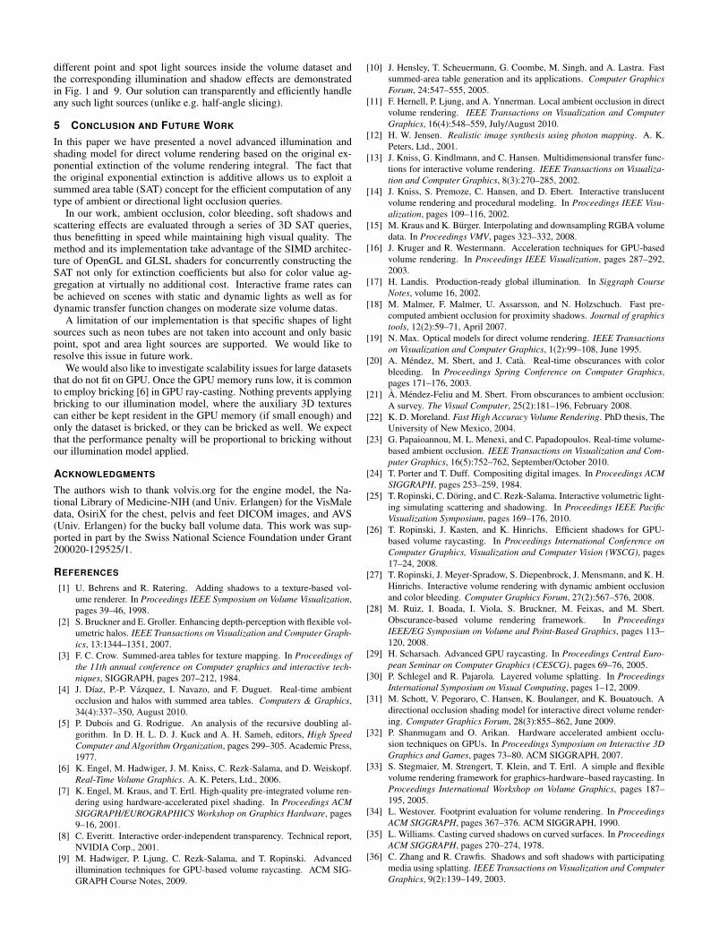
Fig. 11. The engine dataset rendered with different SAT resolutions of 643, 1283, 1923 and 2563 and 40 cone samples (from left to right). Even lowerSAT sizes will result in more blurred shadows but not expose conspicuous artifacts.
Fig. 12. As few as 12 cone samples are sufficient until cuboid artifactsbecome clearly visible for a SAT resolution of 1283. The image on theleft shows the difference to the respective image from Figure 11.
color bleeding. Hence we can see that even for dynamic TF changesan interactive feedback can be achieved. The influence of the SAT sizeon the rendering is shown in Fig. 11, demonstrating that the SAT sizecan easily be set at a fraction of the size of the volume dataset itself.
Table 2 shows the time required for computing the actual terms forambient occlusion/color bleeding by approximating the neighborhoodof every voxel with cuboid shells. The time is only dependent on thevolume size and the number of shells but not on the neighborhood ra-dius in contrast to explicit neighborhood sampling. Nevertheless, thelast column shows the time for explicitly sampling a neighborhoodof radius 7 (= 4
3 π73 samples) to demonstrate the large time cost dif-ference. Thus even if not cached, ambient occlusion/color bleedingeffects can be computed in real-time for these volume models. The
AO Shadow 11 7 3 SampledTexture Size Shells Shells Shells Radius=764 x 64 x 64 0.0039s 0.0030s 0.0022s 0.2099s
128 x 128 x 128 0.0202s 0.0126s 0.0065s 0.4441s192 x 192 x 192 0.0606s 0.0348s 0.0147s 1.4280s256 x 256 x 256 0.1382s 0.0791s 0.0307s 3.0818s
Table 2. Time needed for computing the AO/color bleeding terms for dif-ferent light cache texture sizes and numbers of shells. The last columnshows the time for explicitly sampling the neighborhood of radius r = 7.
head in Fig. 2 was rendered using a 1923 AO texture with 15 shells.Note that combining SAT construction and AO computation times
for an example as in Fig. 2 results in a fairly low cost of only about0.073s. This highly interactive SAT and AO computation avoids costlypreprocessing [27] to achieve TF independence.
Table 3 shows the time required for computing directional softshadows for two different cuboidal cone approximation resolutions.The time required and the quality obviously depend on the samplingparameters. The last column shows the time for a single, classicalshadow ray with a sampling rate of 250 samples per unit (the sidelength of volume dataset). In fact, to get equally soft shadows, the costof a single shadow ray would have to be multiplied by a factor ( 1)because sampling would have to be performed within an entire coneand not only on the ray.
Soft Shadow 50 20 1 ShadowTexture Size Samples Samples Ray64 x 64 x 64 0.0079s 0.0061s 0.0098s
128 x 128 x 128 0.0385s 0.0270s 0.0361s192 x 129 x 129 0.1166s 0.0816s 0.0954s256 x 256 x 256 0.2671s 0.1821s 0.2105s
Table 3. Time required for computing directional soft shadows for dif-ferent volume sizes and two different cone samplings. The last columnshows the time for a single, classical shadow ray with a sampling rate of250 samples per unit (the side length of the volume).
For the engine in Fig. 4 and the first medical dataset in Fig. 8 it issufficient to use a 643 AO/shadow texture with 50 samples per unit,consuming only 0.0079s/frame for shadow computations, to achievea very good image quality. The second medical dataset in Fig. 8was rendered using a 1283 AO/shadow texture with 50 samples, us-ing 0.0385s/frame for shadow computations. The Cornell box in Fig. 6was rendered using a 2563 AO/shadow texture with 60 samples but up-dated only upon TF changes due to the fixed embedded light source.Fig. 10 shows the effects of different cone angles. Fig. 12 demon-strates the artifacts from the cuboids that become visible if only veryfew cone samples are used.
The scattering of light in smoke, thick fog or wax-like media withnon-zero opacity is demonstrated in Fig. 9, clearly showing the ex-pected light shafts and diffusely scattered light propagation. Multiple
different point and spot light sources inside the volume dataset andthe corresponding illumination and shadow effects are demonstratedin Fig. 1 and 9. Our solution can transparently and efficiently handleany such light sources (unlike e.g. half-angle slicing).
5 CONCLUSION AND FUTURE WORK
In this paper we have presented a novel advanced illumination andshading model for direct volume rendering based on the original ex-ponential extinction of the volume rendering integral. The fact thatthe original exponential extinction is additive allows us to exploit asummed area table (SAT) concept for the efficient computation of anytype of ambient or directional light occlusion queries.
In our work, ambient occlusion, color bleeding, soft shadows andscattering effects are evaluated through a series of 3D SAT queries,thus benefitting in speed while maintaining high visual quality. Themethod and its implementation take advantage of the SIMD architec-ture of OpenGL and GLSL shaders for concurrently constructing theSAT not only for extinction coefficients but also for color value ag-gregation at virtually no additional cost. Interactive frame rates canbe achieved on scenes with static and dynamic lights as well as fordynamic transfer function changes on moderate size volume datas.
A limitation of our implementation is that specific shapes of lightsources such as neon tubes are not taken into account and only basicpoint, spot and area light sources are supported. We would like toresolve this issue in future work.
We would also like to investigate scalability issues for large datasetsthat do not fit on GPU. Once the GPU memory runs low, it is commonto employ bricking [6] in GPU ray-casting. Nothing prevents applyingbricking to our illumination model, where the auxiliary 3D texturescan either be kept resident in the GPU memory (if small enough) andonly the dataset is bricked, or they can be bricked as well. We expectthat the performance penalty will be proportional to bricking withoutour illumination model applied.
ACKNOWLEDGMENTS
The authors wish to thank volvis.org for the engine model, the Na-tional Library of Medicine-NIH (and Univ. Erlangen) for the VisMaledata, OsiriX for the chest, pelvis and feet DICOM images, and AVS(Univ. Erlangen) for the bucky ball volume data. This work was sup-ported in part by the Swiss National Science Foundation under Grant200020-129525/1.
REFERENCES
[1] U. Behrens and R. Ratering. Adding shadows to a texture-based vol-ume renderer. In Proceedings IEEE Symposium on Volume Visualization,pages 39–46, 1998.
[2] S. Bruckner and E. Groller. Enhancing depth-perception with flexible vol-umetric halos. IEEE Transactions on Visualization and Computer Graph-ics, 13:1344–1351, 2007.
[3] F. C. Crow. Summed-area tables for texture mapping. In Proceedings ofthe 11th annual conference on Computer graphics and interactive tech-niques, SIGGRAPH, pages 207–212, 1984.
[4] J. Dıaz, P.-P. Vazquez, I. Navazo, and F. Duguet. Real-time ambientocclusion and halos with summed area tables. Computers & Graphics,34(4):337–350, August 2010.
[5] P. Dubois and G. Rodrigue. An analysis of the recursive doubling al-gorithm. In D. H. L. D. J. Kuck and A. H. Sameh, editors, High SpeedComputer and Algorithm Organization, pages 299–305. Academic Press,1977.
[6] K. Engel, M. Hadwiger, J. M. Kniss, C. Rezk-Salama, and D. Weiskopf.Real-Time Volume Graphics. A. K. Peters, Ltd., 2006.
[7] K. Engel, M. Kraus, and T. Ertl. High-quality pre-integrated volume ren-dering using hardware-accelerated pixel shading. In Proceedings ACMSIGGRAPH/EUROGRAPHICS Workshop on Graphics Hardware, pages9–16, 2001.
[8] C. Everitt. Interactive order-independent transparency. Technical report,NVIDIA Corp., 2001.
[9] M. Hadwiger, P. Ljung, C. Rezk-Salama, and T. Ropinski. Advancedillumination techniques for GPU-based volume raycasting. ACM SIG-GRAPH Course Notes, 2009.
[10] J. Hensley, T. Scheuermann, G. Coombe, M. Singh, and A. Lastra. Fastsummed-area table generation and its applications. Computer GraphicsForum, 24:547–555, 2005.
[11] F. Hernell, P. Ljung, and A. Ynnerman. Local ambient occlusion in directvolume rendering. IEEE Transactions on Visualization and ComputerGraphics, 16(4):548–559, July/August 2010.
[12] H. W. Jensen. Realistic image synthesis using photon mapping. A. K.Peters, Ltd., 2001.
[13] J. Kniss, G. Kindlmann, and C. Hansen. Multidimensional transfer func-tions for interactive volume rendering. IEEE Transactions on Visualiza-tion and Computer Graphics, 8(3):270–285, 2002.
[14] J. Kniss, S. Premoze, C. Hansen, and D. Ebert. Interactive translucentvolume rendering and procedural modeling. In Proceedings IEEE Visu-alization, pages 109–116, 2002.
[15] M. Kraus and K. Burger. Interpolating and downsampling RGBA volumedata. In Proceedings VMV, pages 323–332, 2008.
[16] J. Kruger and R. Westermann. Acceleration techniques for GPU-basedvolume rendering. In Proceedings IEEE Visualization, pages 287–292,2003.
[17] H. Landis. Production-ready global illumination. In Siggraph CourseNotes, volume 16, 2002.
[18] M. Malmer, F. Malmer, U. Assarsson, and N. Holzschuch. Fast pre-computed ambient occlusion for proximity shadows. Journal of graphicstools, 12(2):59–71, April 2007.
[19] N. Max. Optical models for direct volume rendering. IEEE Transactionson Visualization and Computer Graphics, 1(2):99–108, June 1995.
[20] A. Mendez, M. Sbert, and J. Cata. Real-time obscurances with colorbleeding. In Proceedings Spring Conference on Computer Graphics,pages 171–176, 2003.
[21] A. Mendez-Feliu and M. Sbert. From obscurances to ambient occlusion:A survey. The Visual Computer, 25(2):181–196, February 2008.
[22] K. D. Moreland. Fast High Accuracy Volume Rendering. PhD thesis, TheUniversity of New Mexico, 2004.
[23] G. Papaioannou, M. L. Menexi, and C. Papadopoulos. Real-time volume-based ambient occlusion. IEEE Transactions on Visualization and Com-puter Graphics, 16(5):752–762, September/October 2010.
[24] T. Porter and T. Duff. Compositing digital images. In Proceedings ACMSIGGRAPH, pages 253–259, 1984.
[25] T. Ropinski, C. Doring, and C. Rezk-Salama. Interactive volumetric light-ing simulating scattering and shadowing. In Proceedings IEEE PacificVisualization Symposium, pages 169–176, 2010.
[26] T. Ropinski, J. Kasten, and K. Hinrichs. Efficient shadows for GPU-based volume raycasting. In Proceedings International Conference onComputer Graphics, Visualization and Computer Vision (WSCG), pages17–24, 2008.
[27] T. Ropinski, J. Meyer-Spradow, S. Diepenbrock, J. Mensmann, and K. H.Hinrichs. Interactive volume rendering with dynamic ambient occlusionand color bleeding. Computer Graphics Forum, 27(2):567–576, 2008.
[28] M. Ruiz, I. Boada, I. Viola, S. Bruckner, M. Feixas, and M. Sbert.Obscurance-based volume rendering framework. In ProceedingsIEEE/EG Symposium on Volume and Point-Based Graphics, pages 113–120, 2008.
[29] H. Scharsach. Advanced GPU raycasting. In Proceedings Central Euro-pean Seminar on Computer Graphics (CESCG), pages 69–76, 2005.
[30] P. Schlegel and R. Pajarola. Layered volume splatting. In ProceedingsInternational Symposium on Visual Computing, pages 1–12, 2009.
[31] M. Schott, V. Pegoraro, C. Hansen, K. Boulanger, and K. Bouatouch. Adirectional occlusion shading model for interactive direct volume render-ing. Computer Graphics Forum, 28(3):855–862, June 2009.
[32] P. Shanmugam and O. Arikan. Hardware accelerated ambient occlu-sion techniques on GPUs. In Proceedings Symposium on Interactive 3DGraphics and Games, pages 73–80. ACM SIGGRAPH, 2007.
[33] S. Stegmaier, M. Strengert, T. Klein, and T. Ertl. A simple and flexiblevolume rendering framework for graphics-hardware–based raycasting. InProceedings International Workshop on Volume Graphics, pages 187–195, 2005.
[34] L. Westover. Footprint evaluation for volume rendering. In ProceedingsACM SIGGRAPH, pages 367–376. ACM SIGGRAPH, 1990.
[35] L. Williams. Casting curved shadows on curved surfaces. In ProceedingsACM SIGGRAPH, pages 270–274, 1978.
[36] C. Zhang and R. Crawfis. Shadows and soft shadows with participatingmedia using splatting. IEEE Transactions on Visualization and ComputerGraphics, 9(2):139–149, 2003.


![Illumination and shading[vinayak garg]](https://img.pdfslide.net/doc/110x75/58edacda1a28aba22a8b45a3/illumination-and-shadingvinayak-garg.jpg)