Embed Size (px)
Citation preview
Chapter 31: Principles of Active Vibration Control: Electrorheological fluids
Introduction:
Electrorheological (ER) fluids are fluids which exhibit fast and reversible changes in
their rheological properties under the influence of external electrical fields. Electro-
rheological (ER) fluids are a class of smart materials exhibiting significant reversible
changes in their rheological and hence mechanical properties under the influence of
an applied electric field. Efforts are in progress to embed ER fluids in various
structural elements to mitigate vibration problems. ER fluids commonly are composed
of polarisable solid particles dispersed in non conducting oil. Upon the imposition of
external electric field, the particles are polarized and form a chainlike structure along
the direction of the field. The change in apparent viscosity is dependent on the applied
electric field, i.e. the potential divided by the distance between the plates. The change
is not a simple change in viscosity, hence these fluids are now known as ER fluids,
rather than by the older term Electro Viscous fluids. The effect is better described as
an electric field dependent shear yield stress. When activated an ER fluid behaves as a
Bingham plastic (a type of viscoelastic material), with a yield point which is
determined by the electric field strength. After the yield point is reached, the fluid
shears as a fluid, i.e. the incremental shear stress is proportional to the rate of shear (in
a Newtonian fluid there is no yield point and stress is directly proportional to shear).
Hence, the resistance to motion of the fluid can be controlled by adjusting the applied
electric field.
An ERF damper or electrorheological fluid damper, is a type of quick-response active
non-linear damper used in high-sensitivity vibration control. Enhanced actuation and
sensing capabilities of the smart materials have led to effective means of handling
unwanted vibrations in automobile and aerospace industries. Varied physical
phenomena such as the piezoelectric effect, magnetostriction, and electrostriction
underpin the functioning of these materials. The complexity of these phenomena leads
us to the question of characterizing their behaviour in terms of specific parameters of
relevance in a given application. In vibration control applications, one is mostly
concerned with the inertial and viscoelastic properties quantified in terms of the mass,
stiffness and damping, respectively. A brief account of the physics of electro-
rheological (ER) fluids will aid the understanding of their vibration properties.
An electro-active material is a suspension where a semi-conductive material
(particulate or liquid) is dispersed in a dielectric liquid medium. The rheological
properties change in reversible form by several orders of magnitude under external
electric fields. Since, the rheological properties can be easily controlled within a wide
range, many scientific and technological applications may be developed. The potential
applications are as:
Clutch, brake and damping systems, actuators, fuel injections systems
Joints and hands of robotic arms
photonic crystals.
Microswitches.
Mechanical-electronic interfaces
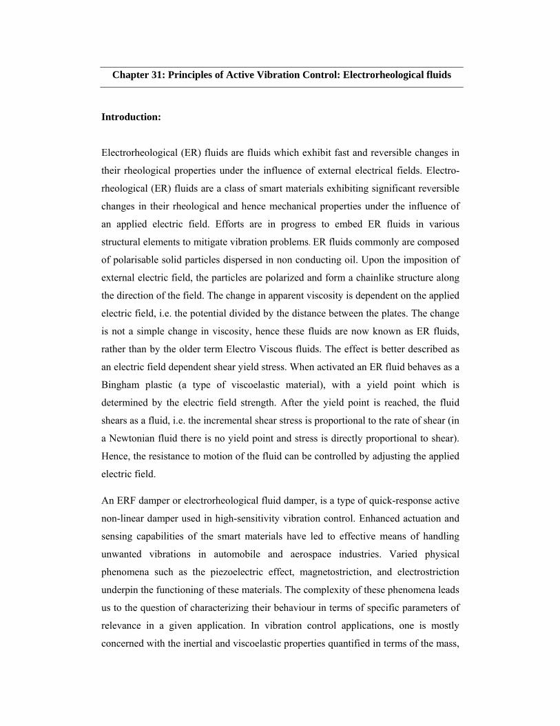
Fig. 8.22 (a) Before an external electric field (b) Structure of an ER materials
after electric field
The interaction between nanoparticles and electric field is explored from the
electrorheological (ER) point of view, using variational formulations for both the
static and dynamic characteristics. Electro-rheological (ER) fluids are suspensions of
extremely fine non-conducting particles (up to 50 micrometres diameter) in an
electrically insulating fluid. Yield strengths of a typical ER fluid are of the order of 10
and 5 kPa under static and dynamic loading conditions, respectively, for electric fields
(both a.c. and d.c.) of the order of a few kVs. Moreover, the change in apparent
viscosity is reversible subject to the presence or absence of electric field. Consider a
dispersion of particles in a fluid medium in which the particles are nano-sized or
otherwise.
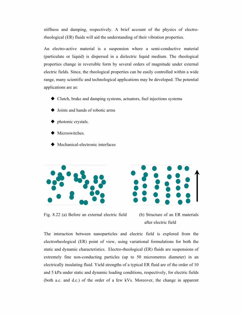
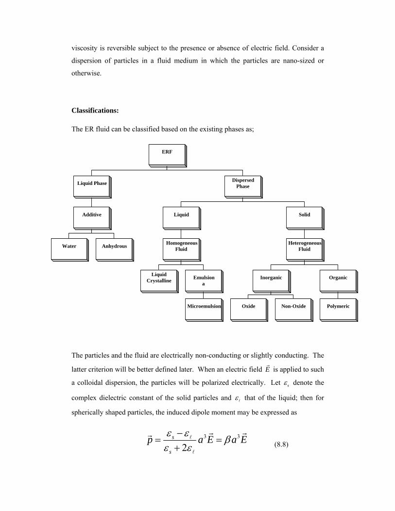
Classifications:
The ER fluid can be classified based on the existing phases as;
The particles and the fluid are electrically non-conducting or slightly conducting. The
latter criterion will be better defined later. When an electric field E
is applied to such
a colloidal dispersion, the particles will be polarized electrically. Let s denote the
complex dielectric constant of the solid particles and that of the liquid; then for
spherically shaped particles, the induced dipole moment may be expressed as
3 3
2s
s
p a E a E
(8.8)
ERF
Liquid Phase
Additive
Water Anhydrous
Dispersed Phase
Liquid
Homogeneous Fluid
Liquid Crystalline
Emulsiona
Microemulsion
Solid
Heterogeneous Fluid
Inorganic
Oxide Non-Oxide
Organic
Polymeric

where a is the radius of the particles. Here E
should be understood as the field at the
location of the particle. The resulting (induced) dipole-dipole interaction between the
particles means that the random dispersion is not the lowest energy state of the
system, and particles would tend to aggregate and form chains/columns along the
applied field direction. The formation of chains/columns is the reason why such
colloids exhibit an increased viscosity or even solid-like behavior when sheared in a
direction perpendicular to the electric field. Such rheological variation is denoted the
electrorheological effect, or ER effect. And the colloids which exhibit significant ER
effect are denoted electrorheological fluids, or ER fluids. The formation of
chains/columns is governed by the competition between electrical energy and entropy
of the particles, manifest in the value of the dimensionless parameter / Bp E k T
,
where Bk is the Boltzmann constant and T the temperature. For room temperature
and p
given by above Eq., 1 defines the boundary between the entropy-
dominated regime and the ER regime. The resulting relation between the electric
field and the size of the particle, given by 3 1/3( )a , is shown in Fig. 8.23.
0 10000 20000 30000 40000 500001
10
100
1000
E (Volt/cm)
Entropy effect dominates
ER effect dominates
(
3 )(1/3
) (nm
)
Figure 8.23: A plot of the curve / 1B
p E k T
, above which the ER
effect dominates and below which the entropy effect dominates.
Typical response times of ER fluids are of the order of a few milliseconds. The
apparent viscosity of these fluids changes reversibly by an order of up to 100,000 in
response to an electric field. For example, a typical ER fluid can go from the
consistency of a liquid to that of a gel, and back, with response times on the order of
milliseconds. ER fluids are fluids with controllable rheological properties. When an
electric field is applied to these fluids, they respond by forming chain-like structures
which results in enhancement of apparent viscosity by as high as five orders of
magnitude. This results in a significant increase in the yield strength of the material.
ER fluid composition and theory
ER fluids are a type of smart fluid. A simple ER fluid can be made by mixing
cornflour in a light vegetable oil or (better) Silicone oil. There are two main theories
to explain the effect: the interfacial tension or 'water bridge' theory, and the
electrostatic theory. The water bridge theory assumes a three phase system, the
particles contain the third phase which is another liquid (e.g. water) immiscible with
the main phase liquid (e.g. oil). With no applied electric field the third phase is
strongly attracted to and held within the particles. This means the ER fluid is a
suspension of particles, which behaves as a liquid. When an electric field is applied
the third phase is driven to one side of the particles by electro osmosis and binds
adjacent particles together to form chains. This chain structure means the ER fluid has
become a solid. The electrostatic theory assumes just a two phase system, with
dielectric particles forming chains aligned with an electric field in an analogous way
to how magneto-rheological fluid (MR) fluids work. An ER fluid has been
constructed with the solid phase made from a conductor coated in an insulator. This
ER fluid clearly cannot work by the water bridge model. However, although
demonstrating that some ER fluids work by the electrostatic effect, it does not prove
that all ER fluids do so. The advantage of having an ER fluid which operates on the
electrostatic effect is the elimination of leakage current, i.e. potentially there is no DC
current. Of course, since ER devices behave electrically as capacitors, and the main
advantage of the ER effect is the speed of response, an AC current is to be expected.
The particles are electrically active. They can be ferroelectric or, as mentioned above,
made from a conducting material coated with an insulator, or electro-osmotically
active particles. In the case of ferroelectric or conducting material, the particles would
have a high dielectric constant. There may be some confusion here as to the dielectric
constant of a conductor, but "if a material with a high dielectric constant is placed in
an electric field, the magnitude of that field will be measurably reduced within the
volume of the dielectric" (see main page: Dielectric constant), and since the electric
field is zero in an ideal conductor, then in this context the dielectric constant of a
conductor is infinite.
Another factor that influences the ER effect is the geometry of the electrodes. The
introduction of parallel grooved electrodes showed slight increase in the ER effect but
perpendicular grooved electrodes doubled the ER effect. A much larger increase in
ER effect can be obtained by coating the electrodes with electrically polarisable
materials. This turns the usual disadvantage of dielectrophoresis into a useful effect. It
also has the effect of reducing leakage currents in the ER fluid.
The giant electrorheological (GER) fluid was discovered in 2003, and is able to
sustain higher yield strengths than many other ER fluids. The GER fluid consists of
Urea coated nanoparticles of Barium Titanium Oxalate suspended in silicone oil. The
high yield strength is due to the high dielectric constant of the particles, the small size
of the particles and the Urea coating. Another advantage of the GER is that the
relationship between the electrical field strength and the yield strength is linear after
the electric field reaches 1 kV/mm. The GER is a high yield strength, but low
electrical field strength and low current density fluid compared to many other ER
fluids. The procedure for preparation of the suspension is given in. The major concern
is the use of oxalic acid for the preparation of the particles as it is a strong organic
acid.
APPLICATIONS
The normal application of ER fluids is in fast acting hydraulic valves and clutches,
with the separation between plates being in the order of 1 mm and the applied
potential being in the order of 1 kV. In simple terms, when the electric field is
applied, an ER hydraulic valve is shut or the plates of an ER clutch are locked
together, when the electric field is removed the ER hydraulic valve is open or the
clutch plates are disengaged.
Other common applications are in ER brakes (think of a brake as a clutch with one
side fixed) and shock absorbers (which can be thought of as closed hydraulic systems
where the shock is used to try and pump fluid through a valve).
There are many novel uses for these fluids, including use in the US army's
planned future force warrior project. They plan to create bulletproof vests using an ER
fluid because the ability to soak the fluid into cloth creates the potential for a very
light vest that can change from a normal cloth into a hard covering almost
instantaneously. Other potential uses are in accurate abrasive polishing and as haptic
controllers and tactile displays.
ER fluid has also been proposed to have potential applications in flexible electronics,
with the fluid incorporated in elements such as rollable screens and keypads, in which
the viscosity-changing qualities of the fluid allowing the rollable elements to become
rigid for use, and flexible to roll and retract for storing when not in use. Motorola filed
a patent application for mobile device applications in 2006.
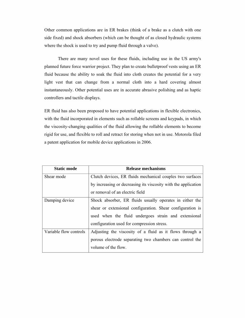
Static mode Release mechanisms
Shear mode Clutch devices, ER fluids mechanical couples two surfaces
by increasing or decreasing its viscosity with the application
or removal of an electric field
Damping device Shock absorber, ER fluids usually operates in either the
shear or extensional configuration. Shear configuration is
used when the fluid undergoes strain and extensional
configuration used for compression stress.
Variable flow controls Adjusting the viscosity of a fluid as it flows through a
porous electrode separating two chambers can control the
volume of the flow.
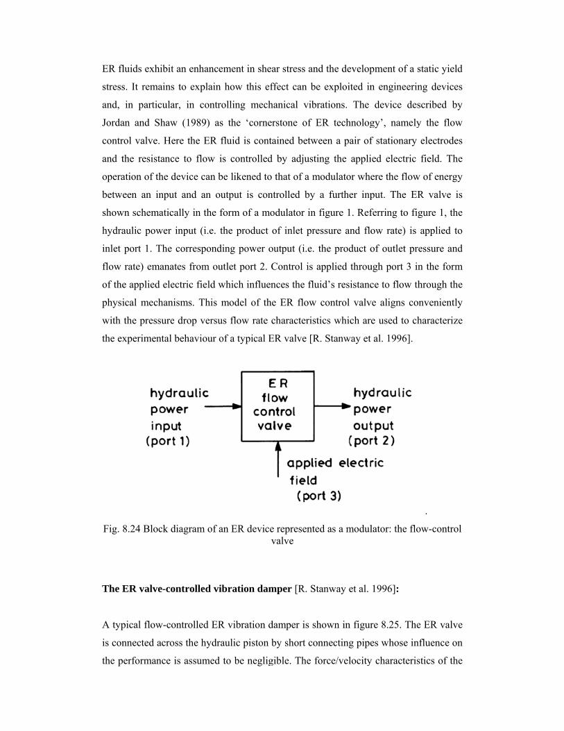
ER fl
stress
and,
Jorda
contr
and t
opera
betwe
show
hydra
inlet
flow
of the
physi
with
the ex
Fig. 8
The E
A typ
is con
the p
luids exhibit
s. It remains
in particula
an and Shaw
rol valve. He
the resistanc
ation of the d
een an inpu
wn schematic
aulic power
port 1. The
rate) emana
e applied ele
ical mechan
the pressure
xperimental
8.24 Block d
ER valve-co
pical flow-co
nnected acro
erformance
t an enhance
s to explain
ar, in contro
w (1989) as
ere the ER f
ce to flow i
device can b
ut and an ou
cally in the f
input (i.e. t
correspondi
ates from ou
ectric field w
nisms. This m
e drop versu
behaviour o
diagram of a
ontrolled vib
ontrolled ER
oss the hydra
is assumed
ement in shea
how this ef
olling mech
s the ‘corner
fluid is conta
s controlled
be likened to
utput is con
form of a mo
the product
ing power o
utlet port 2. C
which influen
model of the
us flow rate c
of a typical E
an ER devicev
bration dam
R vibration d
aulic piston b
to be neglig
ar stress and
ffect can be
hanical vibra
rstone of E
ained betwe
d by adjustin
that of a mo
ntrolled by a
odulator in f
of inlet pres
output (i.e. th
Control is ap
nces the flui
e ER flow c
characteristi
ER valve [R.
e representedvalve
mper [R. Sta
damper is sho
by short con
gible. The fo
d the develop
exploited in
ations. The
R technolog
een a pair of
ng the appli
odulator whe
a further inp
figure 1. Ref
ssure and flo
he product o
pplied throu
id’s resistanc
control valv
cs which are
Stanway et
d as a modul
anway et al.
own in figur
nnecting pipe
orce/velocity
pment of a s
n engineerin
device des
gy’, namely
f stationary e
ed electric f
ere the flow
put. The ER
ferring to fig
ow rate) is a
of outlet pre
ugh port 3 in
ce to flow th
ve aligns con
e used to ch
al. 1996].
lator: the flo
1996]:
re 8.25. The
es whose inf
y characterist
tatic yield
ng devices
cribed by
y the flow
electrodes
field. The
of energy
R valve is
gure 1, the
applied to
essure and
n the form
hrough the
nveniently
haracterize
.
w-control
ER valve
fluence on
tics of the
piston
(stead
volum
nume
defin
of the
The n
solvin
mean
thus
multi
piston
the d
versu
with
techn
Peel e
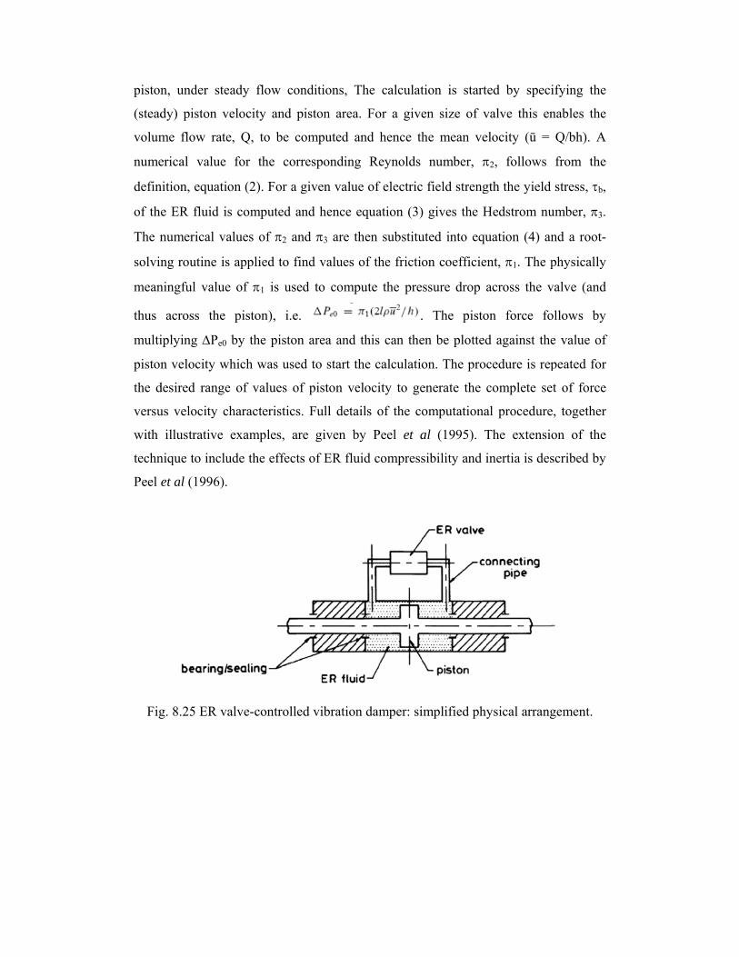
Fig
n, under ste
dy) piston v
me flow rate
erical value
nition, equati
e ER fluid i
numerical va
ng routine is
ningful value
across the
iplying Pe0
n velocity w
desired range
us velocity c
illustrative
nique to inclu
et al (1996).
g. 8.25 ER v
eady flow c
velocity and
e, Q, to be
for the co
ion (2). For a
is computed
alues of 2
s applied to
e of 1 is u
piston), i.
by the pisto
which was us
e of values
characteristic
examples,
ude the effec
.
valve-control
conditions, T
piston area
computed a
orresponding
a given valu
and hence e
and 3 are t
find values
sed to comp
e.
on area and
sed to start t
of piston ve
cs. Full deta
are given b
cts of ER flu
lled vibration
The calculat
a. For a give
and hence th
g Reynolds
ue of electric
equation (3)
then substitu
of the fricti
pute the pre
.
this can the
the calculatio
elocity to ge
ails of the c
by Peel et a
uid compress
n damper: si
tion is start
en size of v
he mean ve
number,
c field streng
) gives the H
uted into equ
on coefficie
essure drop a
. The pisto
en be plotted
on. The proc
enerate the c
omputationa
al (1995). T
sibility and i
implified phy
ted by speci
valve this en
elocity (ū =
2, follows
gth the yield
Hedstrom nu
uation (4) an
nt, 1. The p
across the v
on force fo
d against the
cedure is rep
complete se
al procedure
The extensio
inertia is des
ysical arrang
ifying the
nables the
Q/bh). A
from the
stress, b,
umber, 3.
nd a root-
physically
valve (and
ollows by
e value of
peated for
et of force
e, together
on of the
scribed by
gement.

Vibr
In th
assoc
arran
valve
provi
rotati
electr
linear
figure
expla
betwe
behav
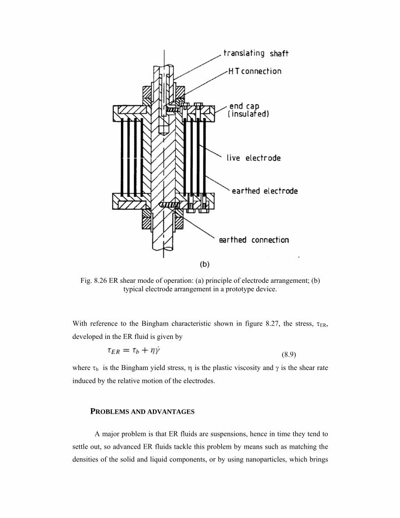
ation damp
he ER valv
ciated with
ngement. The
e which was
iding dampi
ing electrode
rodes transla
r configurati
e 8.26 (b) sh
ained by Co
een sliding
viour of a Bi
ping by direc
e-controlled
the vibratio
e force/veloc
s constructed
ing involves
es. If the el
ate then we h
ion is shown
hows a typic
oulter et al
electrodes c
ingham plast
ct shear
d damper de
on was acc
city profile o
d with fixed
s the direct
lectrodes rot
have a linea
n in figure 8
al arrangem
(1993a) tha
can be mode
tic.
escribed pre
commodated
of the dampe
d electrodes
t shearing o
tate then we
ar damper. T
8.26. Figure
ent of electr
at the behav
eled on the
eviously, th
d by a hydr
er was modu
. An alterna
of fluids be
e have a tor
The arrangem
8.26 (a) sho
rodes in a pro
viour of ER
basis of the
he oscillator
raulic piston
ulated throug
ative arrang
etween tran
rsional damp
ment of elect
ows the prin
ototype devi
fluids bein
e idealized p
ry motion
n/cylinder
gh the ER
ement for
slating or
per; if the
trodes in a
nciple and
ice. It was
g sheared
post-yield
Fig
With
devel
wher
induc
settle
densi
g. 8.26 ER s
reference t
loped in the
e b is the B
ced by the re
PROBLEM
A major p
e out, so adv
ities of the s
shear mode otypical elect
to the Bingh
ER fluid is g
Bingham yie
elative motio
MS AND ADV
problem is th
vanced ER fl
solid and liqu
of operation:trode arrang
ham charact
given by
eld stress,
on of the elec
VANTAGES
hat ER fluid
fluids tackle
uid compon
: (a) principlement in a p
eristic show
is the plasti
ctrodes.
S
ds are suspen
this problem
nents, or by u
le of electrodprototype dev
wn in figure
ic viscosity a
nsions, henc
m by means
using nanop
de arrangemvice.
8.27, the st
(8.9)
and is the
ce in time the
such as mat
particles, whi
ent; (b)
tress, ER,
shear rate
ey tend to
tching the
ich brings
ER f
probl
field
An ad
than t
But t
contr
Unfo
rheol
chang
Howe
electr
been
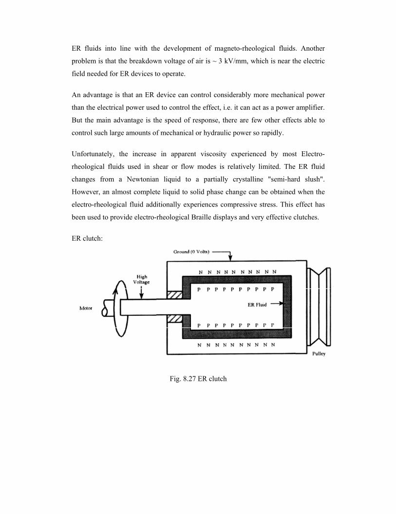
ER cl
fluids into l
lem is that th
needed for E
dvantage is
the electrica
the main adv
rol such large
rtunately, th
logical fluid
ges from a
ever, an alm
ro-rheologic
used to prov
lutch:
line with th
he breakdow
ER devices t
that an ER
al power used
vantage is th
e amounts o
he increase
ds used in sh
a Newtonian
most complet
cal fluid add
vide electro-
he developm
wn voltage o
to operate.
device can c
d to control
he speed of
f mechanica
in apparen
hear or flow
n liquid to
te liquid to s
ditionally exp
rheological
Fig. 8.2
ment of mag
f air is ~ 3 k
control cons
the effect, i.
response, th
al or hydraul
nt viscosity
w modes is
a partially
solid phase c
periences co
Braille displ
27 ER clutch
gneto-rheolo
kV/mm, whi
siderably mo
.e. it can act
here are few
ic power so
y experience
relatively li
y crystalline
change can
ompressive s
lays and very
h
gical fluids
ich is near th
ore mechani
as a power
w other effec
rapidly.
ed by most
imited. The
e "semi-har
be obtained
stress. This
y effective c
. Another
he electric
cal power
amplifier.
cts able to
t Electro-
ER fluid
rd slush".
when the
effect has
clutches.