Embed Size (px)
Citation preview
ODOT ROADWAY DRAINAGE MANUAL
November 2014
Chapter 6
DOCUMENTATION

ODOT Roadway Drainage Manual November 2014
Documentation 6-i
Chapter 6 DOCUMENTATION
Table of Contents
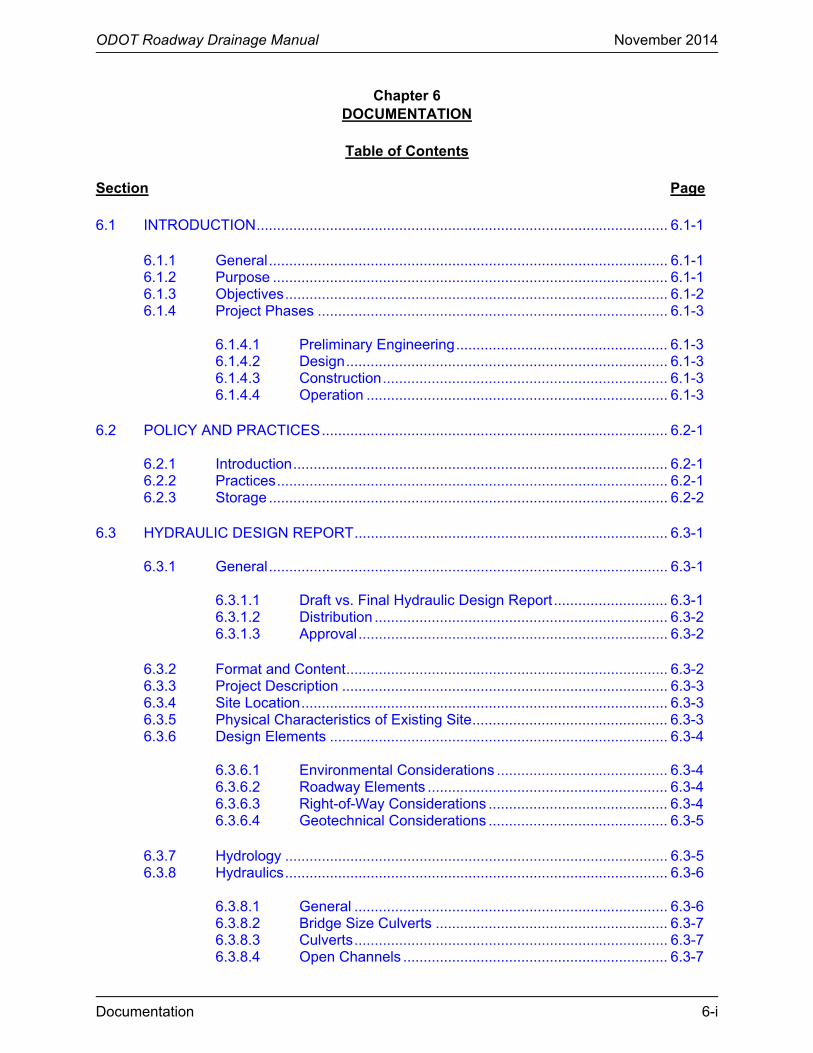
Section Page 6.1 INTRODUCTION ..................................................................................................... 6.1-1
6.1.1 General .................................................................................................. 6.1-1 6.1.2 Purpose ................................................................................................. 6.1-1 6.1.3 Objectives .............................................................................................. 6.1-2 6.1.4 Project Phases ...................................................................................... 6.1-3
6.1.4.1 Preliminary Engineering .................................................... 6.1-3 6.1.4.2 Design ............................................................................... 6.1-3 6.1.4.3 Construction ...................................................................... 6.1-3 6.1.4.4 Operation .......................................................................... 6.1-3
6.2 POLICY AND PRACTICES ..................................................................................... 6.2-1
6.2.1 Introduction ............................................................................................ 6.2-1 6.2.2 Practices ................................................................................................ 6.2-1 6.2.3 Storage .................................................................................................. 6.2-2
6.3 HYDRAULIC DESIGN REPORT ............................................................................. 6.3-1
6.3.1 General .................................................................................................. 6.3-1
6.3.1.1 Draft vs. Final Hydraulic Design Report ............................ 6.3-1 6.3.1.2 Distribution ........................................................................ 6.3-2 6.3.1.3 Approval ............................................................................ 6.3-2
6.3.2 Format and Content ............................................................................... 6.3-2 6.3.3 Project Description ................................................................................ 6.3-3 6.3.4 Site Location .......................................................................................... 6.3-3 6.3.5 Physical Characteristics of Existing Site ................................................ 6.3-3 6.3.6 Design Elements ................................................................................... 6.3-4
6.3.6.1 Environmental Considerations .......................................... 6.3-4 6.3.6.2 Roadway Elements ........................................................... 6.3-4 6.3.6.3 Right-of-Way Considerations ............................................ 6.3-4 6.3.6.4 Geotechnical Considerations ............................................ 6.3-5
6.3.7 Hydrology .............................................................................................. 6.3-5 6.3.8 Hydraulics .............................................................................................. 6.3-6
6.3.8.1 General ............................................................................. 6.3-6 6.3.8.2 Bridge Size Culverts ......................................................... 6.3-7 6.3.8.3 Culverts ............................................................................. 6.3-7 6.3.8.4 Open Channels ................................................................. 6.3-7
ODOT Roadway Drainage Manual November 2014
6-ii Documentation
Table of Contents (Continued)
Section Page
6.3.8.5 Storm Drains ..................................................................... 6.3-8 6.3.8.6 Pump Stations ................................................................... 6.3-8
6.4 RECORDS AND FILES ........................................................................................... 6.4-1
6.4.1 General Information Section ................................................................. 6.4-1 6.4.2 Hydraulic Site Information Section ........................................................ 6.4-1
6.4.2.1 Hydraulic Site Information Checklist ................................. 6.4-2 6.4.2.2 Design Computations ........................................................ 6.4-2 6.4.2.3 Site-Specific Correspondence .......................................... 6.4-2
6.4.3 Permit Information Section .................................................................... 6.4-3 6.4.4 Maintenance of Files ............................................................................. 6.4-3
6.5 REFERENCES ........................................................................................................ 6.5-1 APPENDIX 6.A HYDRAULIC DESIGN REPORT ............................................................... 6.A-1
6.A.1 Location of the Site ................................................................................ 6.A-1 6.A.2 General Information ............................................................................... 6.A-1 6.A.3 Peak Discharges Computation .............................................................. 6.A-2 6.A.4 Extreme Highwater ................................................................................ 6.A-2 6.A.5 Existing Structure .................................................................................. 6.A-2 6.A.6 Proposed Structure ................................................................................ 6.A-3 6.A.7 List of Exhibits ....................................................................................... 6.A-4

ODOT Roadway Drainage Manual November 2014
List of Figures 6-iii
List of Figures
Figure Page Figure 6.4-A ⎯ ODOT DOCUMENTATION PROJECT CHECKLIST .................................. 6.4-4

ODOT Roadway Drainage Manual November 2014
Documentation 6.1-1
Chapter 6 DOCUMENTATION
6.1 INTRODUCTION
6.1.1 General
Hydrologic and hydraulic documentation as used in this Chapter is the compilation and preservation of the design and related details and all pertinent information on which the design and decisions are based. This includes the drainage area and other maps, field survey information, source references, photographs, engineering calculations and analyses, measurements and flood history. The objectives of properly documented hydraulic studies include:
• demonstration of the standards used for public safety;
• justification of expenditure of public funds;
• future reference by designers for improvements, changes or rehabilitations that are made to the highway facilities;
• information leading to the development of a defense for litigation; and
• public information.
Plans, specifications and analyses are often referred to long after the actual construction has been completed. Documentation allows the evaluation of the performance of structures after flood events to determine if the structures performed as anticipated, or to establish the cause of unexpected behavior. In case of failure, it is essential that contributing factors can be identified so that recurring damage can be avoided.
6.1.2 Purpose
The major purpose of providing good documentation is to define the design procedure used and to demonstrate how the final design and decisions were determined. Documentation should be viewed as the record of reasonable and prudent design analysis based on the best available technology and information. Good documentation can provide the following:
• tort liability protection by proving that reasonable and prudent actions were, in fact, taken. Documentation should not increase the potential court award and may decrease it by disproving any claims of negligence by the plaintiff;
• identification of the standard of practice used at the time of design, which might be very important if legal action occurs in the future;
ODOT Roadway Drainage Manual November 2014
6.1-2 Documentation
• evidence that rationally accepted procedures and analyses were used at the time of the design that were appropriate for the perceived site importance and flood hazard (this should further disprove any negligence claims);
• continuous site history to facilitate future reconstruction;
• file data necessary to quickly evaluate any future site problems that might occur during the facility’s service life; and
• expedited plan development by clearly providing the reasons and rationale for specific design decisions.
6.1.3 Objectives
Following are ODOTs overall objectives for the documentation of hydrologic and hydraulic designs and analyses:
• Compile hydrologic and hydraulic data, preliminary calculations and analyses and all related information used in developing conclusions and recommendations related to drainage requirements, including estimates of structure size and location.
• Document all design assumptions and selected criteria including the related decisions.
• Include sufficient detail for each design or analysis to be appropriate for the risk and the importance of the facility.
• Organize documentation to be as concise and complete as practical so that future hydraulics designers can understand what was performed by predecessors.
• Circumvent incriminating statements wherever possible by stating uncertainties in less than specific terms. For example, “the culvert may cause backwater” rather than “the culvert will cause backwater.”
• Provide all related references to include items such as published data and reports, memos, letters and interviews. Include dates and signatures where appropriate.
• Include data and information from the conceptual stage of project development through service life to provide successors with all information.
• Organize documentation to logically lead the reader from past history through the problem background, into the findings and through the performance.
• Summarize lengthy documentation assemblies; a summary and table of contents at the beginning of the project file will provide an outline of the documentation presented to assist users in finding detailed information.
ODOT Roadway Drainage Manual November 2014
Documentation 6.1-3
6.1.4 Project Phases
The four general phases of any project’s history are preliminary engineering, design, construction and operation/maintenance. Documentation should take place during each phase. The different types of information to be gathered and retained are discussed in the following sections.
6.1.4.1 Preliminary Engineering
Preliminary engineering documentation is the beginning of the formal retention of drainage information supporting the project design. Sufficient detail that provides the basis of decisions, costs and project scope that support finalization of the project environmental document stage should be compiled into the preliminary drainage document.
6.1.4.2 Design
Design documentation should include all information included in the preliminary phase, with any additional studies and additional detail used to justify the design, including information supporting the project specifications especially justification for any formal approvals (including permits) or deviations from organizational standards.
6.1.4.3 Construction
Construction documentation should include all field revisions to the original design, including back-up calculations as well as retention of any photo/video data collected during construction. This information should be added to the same file project developed from preliminary engineering through design.
6.1.4.4 Operation
Operation or maintenance documentation should be continuous over the structure’s life cycle and is commonly comprised of two separate, but equally important components. The first component is the organizations formal drainage structure condition assessment. Such efforts are typically conducted through the maintenance function of the ODOT field divisions. In addition to the regular periodic condition assessment documentation, episodic assessments of critical or high value drainage structures should also be conducted. Such inspection and resulting documentation after significant flood events is commonly a collaborative effort between agency hydraulic and maintenance staff.

ODOT Roadway Drainage Manual November 2014
6.1-4 Documentation
ODOT Roadway Drainage Manual November 2014
Documentation 6.2-1
6.2 POLICY AND PRACTICES
6.2.1 Introduction
A complete hydrologic and hydraulic design and analysis documentation file should be maintained for each project. Where practicable, for each cross drain, major site drain and storm sewer system, this file should include the following:
• identification and location of the facility; • photographs (e.g., grounds and aerial); • hydrology investigations;
o drainage area maps; o vicinity maps and topographic maps; o contour maps; o interviews (e.g., local residents, adjacent property owners, ODOT maintenance
forces); and o newspaper clippings;
• history of performance of existing structure(s); • design notes and correspondence relating to design decisions; • engineering cost estimates; and • actual construction costs. The documentation file should contain design/analysis data and information, which influenced the facility design.
6.2.2 Practices
Following are ODOT practices related to documentation of hydrologic and hydraulic designs and analyses.
• Hydrologic and hydraulic data, preliminary calculations and analyses and all related information used in developing conclusions and recommendations related to drainage requirements, including estimates of structure size and location, should be compiled in a documentation file.
• The hydraulics designer should document all design assumptions and selected criteria including related decisions.
• The amount of detail of documentation for each design or analysis should be commensurate with the risk and the importance of the facility.
• Documentation should be organized to be as concise and complete as practicable. The goal is to provide enough information so that another hydraulics designer can understand and duplicate what was done.
ODOT Roadway Drainage Manual November 2014
6.2-2 Documentation
• Circumvent incriminating statements whenever possible by stating uncertainties in less than specific terms (e.g., the culvert may back water rather than the culvert will back water).
• Provide all related references in the documentation file (e.g., published data and reports, memos and letters, interviews). Include dates and signatures where appropriate.
• Documentation should include data and information from the conceptual stage of project development through service life to provide successors with pertinent information.
• Documentation should be organized chronologically: state past history, problem background, findings and facility performance.
• An executive summary at the beginning of the documentation should provide an outline of the documentation file to assist users in finding detailed information.
• Include the following completed forms for each documentation file:
o the discharge computation forms (e.g., Rational, USGS) as listed in Chapter 7 “Hydrology”; and
o the hard copies of the input and output of the design computations (i.e., HY-8, HEC-RAS, Hydraulic Toolbox) for bridges and culverts, inlets, storm drain systems and hydraulic gradient computations for storm drainage systems (see Chapter 16 “Hydraulic Software”).
6.2.3 Storage
Where and how to store and preserve records is an important consideration. Ease of access, durability, legibility, storage room required and cost are the prime factors to consider when evaluating alternative methods of storage and preservation:
• CD, DVD and hard drives require relatively small storage spaces;
• storage of actual plans and documents requires much more space and the records are not as durable. However, better reproductions can easily be obtained; and
• combinations of these should be used.
The hydraulics designer should maintain the documentation files (e.g., hard copies, CD, DVD, hard drives) where it will be readily available to ODOT for use during construction, for defense of litigation and future replacement or extension. Original plans, project correspondence files, construction modifications and inspection reports are the types of documentation that usually do not need to be duplicated in the hydraulics/hydrology documentation files.
Hydrologic/hydraulic data (e.g. drainage maps, drainage structure records) should be retained in the project plans or other permanent location at least until the drainage facility is totally replaced or modified as a result of a new drainage study.
ODOT Roadway Drainage Manual November 2014
Documentation 6.3-1
6.3 HYDRAULIC DESIGN REPORT
6.3.1 General
The Hydraulic Design Report (HDR) is a comprehensive document used to summarize the hydraulic findings and recommendations and to document the design recommendations for drainage structures and/or channels. An example HDR is provided in Appendix 6.A. Any disagreement with the hydraulic recommendations as prescribed in the Hydraulic Design Report should be resolved prior to final approval by the Engineering Manager of the project or by the Roadway Drainage Engineer.
The Hydraulic Design Report should be tailored to satisfy the requirements of the specific location and size of the project for which the study is required. Too much data and information hinders the objective of locating meaningful information. However, the data that was used in reaching conclusions and recommendations made during the hydraulic studies should be included in the Report.
6.3.1.1 Draft vs. Final Hydraulic Design Report
At the conclusion of the Preliminary Hydraulic Design, the hydraulics designer will prepare the Preliminary Hydraulic Data Sheet and the Draft Hydraulic Design Report. The Report will be considered in draft format until the conclusion of the Final Hydraulic Design, which culminates with the completion of the Final Hydraulic Data Sheet for culverts. The following paragraphs briefly identify some of the differences between the Draft and Final HDR phases.
At this stage of the study, more than one structure size and type may be considered because the hydraulics designer only needs generalities to obtain a rough estimate of needs and costs. Often, specifics cannot be provided until individual structures have been selected for each site and subsequent final hydraulic computations are performed. Sometimes, however, the HDR will require detailed design studies to justify the extent of mitigation required. In general, the more environmentally sensitive sites and those in urbanized areas may necessitate more detail at the preliminary stage.
From previous activities in the project development process, preliminary hydraulic studies will be based on some or all of the following:
• aerial photographs;
• contour maps;
• vicinity maps;
• topographic maps;
• surveyed data reduced to include:
o existing hydraulic facilities; o existing controls;
ODOT Roadway Drainage Manual November 2014
6.3-2 Documentation
o profiles ⎯ roadway, channels, driveways; o cross sections ⎯ roadway, channels, structures; and
• reports from other local, State and Federal agencies, ODOT personnel, newspapers and abutting property owners.
The following data may be available for existing hydraulic structures and should be included in the permanent hydraulic file:
• highwater elevations and flow rates; • ice and drift conditions; • erosion of approach overflow sections, embankments and spur dikes; • stream aggradation or degradation; • scour location, depth and extent; • performance of scour and erosion preventive measures; • meander and bend migration; • performance of stream bank protection and channel stabilization methods; and • cost of maintenance, repair and corrective measures.
6.3.1.2 Distribution
The hydraulics designer will distribute the Hydraulic Data Sheet (Preliminary and Final) as an attachment, with requests for comments and concurrence from those on the distribution list. There will be a separate distribution for the Preliminary and the Final Hydraulic Data Sheets. The distribution lists are as shown on the respective Hydraulic Data Sheets.
6.3.1.3 Approval
The hydraulics designer will forward the Hydraulic Design Report (Draft and Final) to the Engineering Manager in charge of the project or the Roadway Drainage Engineer for approval.
6.3.2 Format and Content
In general, the Hydraulic Design Report should be prepared in the sequence and format discussed in the remainder of Section 6.3. This will provide a uniform presentation for all Hydraulic Design Reports and will ensure that all necessary design elements are addressed. The level of coverage for each item will vary from site-to-site. Although an in-depth discussion for each design element is typically not provided in this Report, sufficient detail should be provided to allow the reader to fully understand the proposed hydraulic design.
ODOT Roadway Drainage Manual November 2014
Documentation 6.3-3
6.3.3 Project Description
This section of the Report should provide a project number and location, and a brief description of the proposed project based on the Scope. If available, also include the project number(s) for the existing facility.
6.3.4 Site Location
The following may be used to define the site location:
• county; • section, township and range; • stream name; • existing structure number; • station number; • distance and direction from nearby cities and towns or route and milepost; and • location map. 6.3.5 Physical Characteristics of Existing Site
The project’s physical characteristics may include a discussion on the following:
• existing road surface type;
• open drainage or closed drainage (i.e., with curb and gutter);
• existing culverts, energy dissipators, storage facilities and other roadway drainage appurtenances;
• general description of surrounding terrain and natural drainage patterns, including direction of flow at crossing;
• size of existing bridge waterway opening (optional, only when needed);
• year when the existing bridge and roadway were built, reconstructed or rehabilitated (optional, only when needed);
• width, length and number of spans of existing structure (optional, only when needed);
• rural or urban location;
• vertical clearance of the existing structure;
• existing overtopping elevation and location, if applicable;
• a description of the major waterway features (e.g., width, location of bends, 100-year flood elevation) optional, only when needed; and
ODOT Roadway Drainage Manual November 2014
6.3-4 Documentation
• any other major physical characteristics related to the project.
6.3.6 Design Elements
The Hydraulic Design Report should provide a general discussion for each of the following design elements, if applicable.
6.3.6.1 Environmental Considerations
Summarize any environmental concerns identified in the available environmental documents. If the environmental document has been approved, include the date and conditions of approval. Also include brief descriptions of any environmental, cultural and/or hazardous waste site mitigation measures required. Note any permits that will be required (e.g., 404 permit, FEMA permit, DEQ permit). Identify the stream’s beneficial use to the general public.
6.3.6.2 Roadway Elements
Document the basic roadway design features of the highway facility:
1. Functional Classification. Note the functional classification of the highway (e.g., urban arterial, rural collector, rural local road).
2. Horizontal Alignment. Identify all major horizontal alignment features affecting the proposed site. Provide the horizontal alignment (including skew) for both the structure and for the approaches.
3. Vertical Alignment. Provide a description for all major vertical alignment features affecting the proposed site. This may include longitudinal grades, vertical curvature and vertical clearances and overtopping elevation and location.
4. Typical Sections. Identify the proposed typical roadway section. This includes the overall roadway or bridge width, approach width, number of travel lanes, travel lane widths, shoulder widths, sidewalks, etc.
Discuss the overall extent of grading for the project. Identify the typical cut and fill slope rates and describe any special proposed slope design for the project (e.g., steep side slopes, rock cuts, non-standard slope rates).
5. Design Speed. Document the design speed used for the roadway design.
6.3.6.3 Right-of-Way Considerations
Briefly describe the existing and proposed right-of-way width. Discuss any impacts that right-of-way considerations may have on the hydraulic design (e.g., open vs. closed drainage). Also, identify any existing or proposed utilities that may impact the hydraulic design.
ODOT Roadway Drainage Manual November 2014
Documentation 6.3-5
Note existing stream access points and stream usage including existing fencing and parking in the vicinity of the project. Identify any public or private access that will be affected by the project. Document approved enhancements or changes to the existing access conditions. Assess and document the right-of-way needs to maintain the existing access or to provide enhancements or other changes as agreed to with other government agencies or private landowners.
6.3.6.4 Geotechnical Considerations
Discuss any geotechnical considerations that impact the hydraulic design of the project (e.g., scour, erosion control).
6.3.7 Hydrology
The hydraulics designer will use Chapter 7 “Hydrology” to perform the hydrologic analysis for the project. This section of the Hydraulic Design Report should document the hydrologic data for the site used in the analysis including:
• description of the drainage area (e.g., size, length, current land use, anticipated development, predominant soil) and identification of source used in determining the watershed boundary (e.g., vicinity map, site map, topographic map if different from USGS maps, aerial photos);
• expected level of development in upstream watershed over the anticipated life of the facility (include source of and basis for these development projections);
• description of the channel and floodplain (e.g., relative width, depth, degree of meandering, stability, vegetative cover). Flow line profile from 500 ft upstream to 500 ft downstream of the proposed structure centerline;
• ravine cross sections that extend above extreme highwater elevations and Manning’s roughness coefficient (n) values assigned to each subsection or break in cover material;
• control structures located upstream and downsteam (e.g., reservoirs, dams, bridges, culverts);
• historical flood events with corresponding highwater elevations;
• design frequency and basis for selection (this may be higher than the typical minimum if in a regulated floodplain);
• hydrologic method(s) used to calculate the discharge (e.g., USGS, Rational, NRCS) and a discussion on the rationale for the design discharge that was selected;
• hydrologic discharge and findings; and
ODOT Roadway Drainage Manual November 2014
6.3-6 Documentation
• flood frequency curves to include design flood, 100-year flood, and any historical floods (optional, only when needed).
6.3.8 Hydraulics
6.3.8.1 General
Features that are important to the hydraulic performance of drainage structures include the approach fill alignment, skew and profile; structure location, skew and length; culvert geometry and end conditions. Design data for the hydraulics of a structure should be assembled in an orderly fashion and retained for future reference. The amount and detail of documentation for each highway-stream crossing system should be appropriate for the risk and the importance of the crossing. For example, a small stream in a rural area would not ordinarily require the same degree of documentation as a small stream in a developed area.
The documentation should include all material used in selecting the design, including notes and observations made from the Preliminary Structure Site Inspection. The documentation should also include the results of studies of alternatives and reasons for rejecting alternatives. The following general information should be documented, as appropriate:
• summarize or reference all pertinent correspondence, field inspection notes, agreements and minutes of meetings, especially those with public involvement;
• landowner concerns (e.g., cattle passes, equipment access, water rights, irrigation);
• environmental concerns, including recommended depths and velocities for high and low fish passage design flows;
• potential flood hazards to adjacent properties;
• relevant information on existing structures in the vicinity;
• observed highwater, dates and discharges (if available);
• evidence of debris problems;
• roadway geometry (plan and profile);
• potential flood hazards to adjacent properties;
• risk assessment, if appropriate, and
• floodway consistency determination or support for and approval of floodway revision.
ODOT Roadway Drainage Manual November 2014
Documentation 6.3-7
6.3.8.2 Bridge Size Culverts
The documentation of the design of bridge size culverts will not be included in this Manual. The hydraulics designer should refer to the ODOT Bridge Manual for more information.
6.3.8.3 Culverts
The hydraulic design of culverts will be based on Chapter 9 “Culverts.” A Hydraulic Design Report will be prepared for all cross drains and major side drains installations. The following information should be documented in the Hydraulic Design Report:
• allowable headwater elevation and basis for its selection (see Chapter 15 “Permits” if FEMA-mapped areas are involved);
• stream profile and cross sections;
• cross section(s) used in the design highwater determinations and their locations;
• roughness coefficient (n value) assignments;
• observed highwater, dates and discharges;
• stage-discharge curve for downstream tailwater channel;
• type of culvert entrance condition;
• culvert outlet appurtenances and energy dissipation calculations and designs; and
• copies of applicable software analyses or standard computation sheets given in Chapter 9 “Culverts.”
6.3.8.4 Open Channels
The hydraulic design of open channels will be based on Chapter 8 “Channels” and Chapter 14 “Bank Protection.” If not included elsewhere, the following items should be documented in the Hydraulic Design Report for open channels:
• stage-discharge curves for the design, check and any historical water surface elevation(s);
• cross section(s) used in the design water surface determinations and their locations;
• roughness coefficient (n value) assignments;
• information on the method used for design water surface determinations;
• channel velocity measurements or estimates and locations;
ODOT Roadway Drainage Manual November 2014
6.3-8 Documentation
• water surface profiles through the reach for the design, check, any historical floods and magnitude and frequency of overtopping flood;
• design or analysis of materials proposed for the channel bed and banks;
• energy dissipation calculations and designs; and
• copies of applicable software analyses.
6.3.8.5 Storm Drains
The hydraulic design of storm drains is based on Chapter 10 “Stormwater Drainage.” If not included elsewhere, the following items should be documented in the Hydraulic Design Report:
• drainage area map;
• a schematic illustrating the storm drainage system layout;
• design frequency;
• information concerning outfalls, existing storm drains and other design considerations;
• computations for drainage areas, inlets and pipes, including hydraulic gradelines (if needed); and
• copies of software output or standard computation sheets given in Chapter 10 “Stormwater Drainage.”
6.3.8.6 Pump Stations
The hydraulic design of pump stations is based on HEC-24, Highway Stormwater Pump Station Design (1). If not included elsewhere, the following items should be documented in the Hydraulic Design Report:
• inflow design hydrograph from upstream drainage area to the pump location; • flood frequency curve for the attenuated peak discharge; • maximum allowable headwater elevations and related probable damage; • starting sequence and elevations; • sump dimensions; • available storage amounts (e.g., sump and storm drain); • pump sizes and recommended operational sequence; and • pump calculations and mass curve routing.
ODOT Roadway Drainage Manual November 2014
Documentation 6.4-1
6.4 RECORDS AND FILES
The hydraulics designer should compile a comprehensive Hydraulic Project File as a permanent record that may be part of the project file. This file may contain general information section, hydraulic site information section and permit information section. It may serve as a resource for:
• retrieving project or site information, • any future litigation, • any future work in the vicinity of the project by ODOT or others, • any future work at the structure site(s), and • maintenance personnel. 6.4.1 General Information Section
The general information section should contain important project information that is not included in the hydraulic site information section. The information should be logically segregated and organized chronologically as seen fit. The contents of the general information section include, but are not limited to:
• summaries of preliminary engineering and design details, • general correspondence, • inspection reports, • computation sheets and check notes for drainage areas and basin slopes, • drainage maps, • environmental reports/studies/impact statements, • construction plans/cross sections, and • original plans. 6.4.2 Hydraulic Site Information Section
The hydraulics designer should create and maintain a separate hydraulic file for each crossing or waterway encroachment on the project in the hydraulic site information section.
Documentation and calculations related to hydrologic and hydraulic design should be retained in the individual hydraulic file. Similar general project information may be filed in the general information section and need not be repeated in each individual hydraulic file.
In the hydraulic site information section, the information should be logically segregated and organized chronologically as seen fit. The key contents of the individual hydraulic file(s) in the hydraulic site information section are as follows:
• hydraulic site information checklist, • design computations, and • site-specific correspondence.
ODOT Roadway Drainage Manual November 2014
6.4-2 Documentation
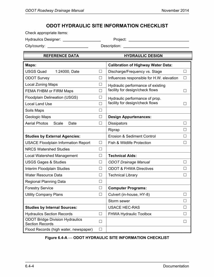
6.4.2.1 Hydraulic Site Information Checklist
Figure 6.4-A is a checklist that can be used to compile the individual hydraulic file in the hydraulic site information section. The items listed establish a minimum requirement consistent with the hydraulic design procedures as outlined in this Manual. If circumstances are such that the drainage facility is sized by other than normal procedures, or if the size of the facility is governed by factors other than hydrologic or hydraulic factors (e.g., the need for farm equipment access), a narrative summary detailing the basis for design should be included in the file. Additionally, the hydraulics designer should include additional items not listed but that are useful in understanding the analysis, design, findings and final recommendations.
6.4.2.2 Design Computations
Hydrologic and hydraulic design computations are an important part of the individual hydraulic file in the hydraulic site information section. The design computations should be maintained for permanent reference during and after construction. They provide a permanent record of design analysis methods, materials used and structure dimensions. The design computations should be in sufficient detail so that others can duplicate the original design.
Arrange the hydrologic and hydraulic design computations so that they can be easily followed by others. The title sheet of the computations should include the project number, project name, county name, station of structure, initials of those who prepared the computations and the date of preparation. Each sheet of the design computations should be thoroughly checked and initialed by the hydraulics designer and the design checker.
When unconventional methods or formulas are used in the hydrologic or hydraulic design, list the sources of the methods or formulas. When different considerations for economic purposes have been used, include all quantities and calculations substantiating these considerations. When computations are made by a computer, identify the program used (including software version) and include the computer input and output values with an explanation of the terms, assumptions and computations used. Provide a sketch with an explanation of all abbreviations and symbols used with the input and output sheets of the program. When using a spreadsheet application, there should be supporting documentation defining the spreadsheet in the file or referenced in the file. See Chapter 16 “Hydraulic Software” for a discussion on hydraulic software.
Some of these items will be included in the Hydraulic Design Report, as previously described.
6.4.2.3 Site-Specific Correspondence
The correspondence portion of the individual hydraulic file in the hydraulic site information section provides a source location for administrative information on the site and a history of the site development. The following correspondence is typically located in the individual hydraulic file in the hydraulic site information section:
1. Agreements. Include copies of any agreements related to the hydraulic design of the site (e.g., for cost sharing of storm sewer infrastructure improvements).
ODOT Roadway Drainage Manual November 2014
Documentation 6.4-3
2. FHWA Correspondence. Include all correspondence sent or received from FHWA on hydraulic issues specific to the site.
3. Internal Department Memoranda. The correspondence file should contain all site-related hydraulic correspondence.
4. Email. Include a hard copy of applicable site-related hydraulic emails.
Similar general project correspondence may be filed in the General File and need not be repeated here. When correspondence refers to a small portion of the sites, either file the correspondence in the General File or place copies in each relevant Site File.
6.4.3 Permit Information Section
The permit information section should include all water-related permit information, including the permit application, its disposition and all relevant back-up data. Chapter 15 “Permits” provides a discussion on water-related permits, which should be used for guidance to identify the contents of this permit information section.
6.4.4 Maintenance of Files
The Hydraulic Project File and all of its contents should be readily available to ODOT personnel for use during construction, for defense of litigation and for future improvements. Hydrologic/hydraulic documentation should be retained permanently even after the drainage facility is totally replaced or modified as a result of a new drainage study.
In general, a scanned electronic copy of the Hydraulic Project File should be retained in the design office. Hard copies can be destroyed in conformance with ODOT records retention policies (see section 5.1.2, Chapter 5 “Data Collection”).
ODOT Roadway Drainage Manual November 2014
6.4-4 Documentation
ODOT HYDRAULIC SITE INFORMATION CHECKLIST Check appropriate items:
Hydraulics Designer: Project:
City/county: Description:
Maps: Calibration of Highway Water Data:
USGS Quad 1:24000, Date Discharge/Frequency vs. Stage
ODOT Survey Influences responsible for H.W. elevation
Local Zoning Maps Hydraulic performance of existing facility for design/check flows
FEMA FHBM or FIRM Maps
Floodplain Delineation (USGS) Hydraulic performance of prop. facility for design/check flows
Local Land Use
Soils Maps
Geologic Maps Design Appurtenances:
Aerial Photos Scale Date Dissipators
Riprap
Studies by External Agencies: Erosion & Sediment Control
USACE Floodplain Information Report Fish & Wildlife Protection
NRCS Watershed Studies
Local Watershed Management Technical Aids:
USGS Gages & Studies ODOT Drainage Manual
Interim Floodplain Studies ODOT & FHWA Directives
Water Resource Data Technical Library
Regional Planning Data
Forestry Service Computer Programs:
Utility Company Plans Culvert (in-house, HY-8)
Storm sewer
Studies by Internal Sources: USACE HEC-RAS
Hydraulics Section Records FHWA Hydraulic Toolbox
ODOT Bridge Division Hydraulics Section Records
Flood Records (high water, newspaper)
Figure 6.4-A ⎯ ODOT HYDRAULIC SITE INFORMATION CHECKLIST
REFERENCE DATA HYDRAULIC DESIGN
ODOT Roadway Drainage Manual November 2014
Documentation 6.4-5
Technical Resources: Data Reports:
ODOT Drainage Manual ODOT Data
FHWA HDS-2 or HDS-5 Other Agency Data
FHWA HEC-22 or HEC-24 Environmental Reports
FEMA
Discharge Calculations: Surface Water Environment Study
USGS NSS Surface Water Environment Study Rev.
Rational Method Location Report
USACE HEC-1 or HEC-HMS Location Revisions Report
NRCS WinTR55 or WinTR20 Drainage Survey Inspection Report
USGS Regression Equations Drainage Survey Inspection Report Rev.
Log-Pearson Type III Hydraulic Design Report
StreamStats Hydraulic Design Report – Revisions
Construction Report
High Water Elevations: Construction Report – Revisions
ODOT Survey Hydraulic Operations Report
External Sources Hydraulic Operations Report – Revisions
Personal Reconnaissance
Flood History:
External Sources
Personal Reconnaissance
ODOT Maintenance Records
Photographs
Local Newspapers
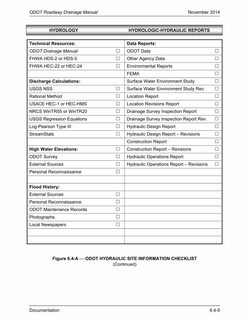
Figure 6.4-A ⎯ ODOT HYDRAULIC SITE INFORMATION CHECKLIST (Continued)
HYDROLOGY HYDROLOGIC-HYDRAULIC REPORTS

ODOT Roadway Drainage Manual November 2014
6.4-6 Documentation
ODOT Roadway Drainage Manual November 2014
Documentation 6.5-1
6.5 REFERENCES
1. FHWA. Highway Stormwater Pump Station Design, Hydraulic Engineering Circular No. 24. Washington, DC : Federal Highway Administration, U.S. Department of Transportation, 2001. FHWA-NHI-01-007.

ODOT Roadway Drainage Manual November 2014
6.5-2 Documentation
ODOT Roadway Drainage Manual November 2014
Documentation 6.A-1
APPENDIX 6.A HYDRAULIC DESIGN REPORT
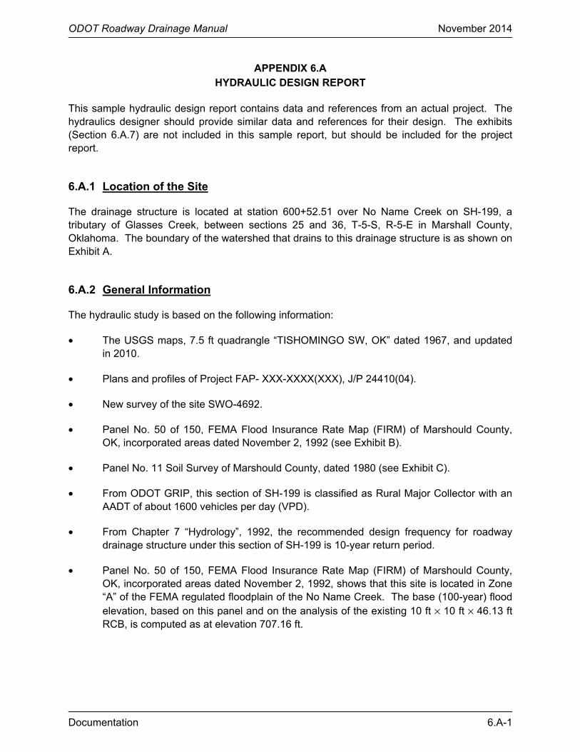
This sample hydraulic design report contains data and references from an actual project. The hydraulics designer should provide similar data and references for their design. The exhibits (Section 6.A.7) are not included in this sample report, but should be included for the project report.
6.A.1 Location of the Site
The drainage structure is located at station 600+52.51 over No Name Creek on SH-199, a tributary of Glasses Creek, between sections 25 and 36, T-5-S, R-5-E in Marshall County, Oklahoma. The boundary of the watershed that drains to this drainage structure is as shown on Exhibit A.
6.A.2 General Information
The hydraulic study is based on the following information:
• The USGS maps, 7.5 ft quadrangle “TISHOMINGO SW, OK” dated 1967, and updated in 2010.
• Plans and profiles of Project FAP- XXX-XXXX(XXX), J/P 24410(04).
• New survey of the site SWO-4692.
• Panel No. 50 of 150, FEMA Flood Insurance Rate Map (FIRM) of Marshould County, OK, incorporated areas dated November 2, 1992 (see Exhibit B).
• Panel No. 11 Soil Survey of Marshould County, dated 1980 (see Exhibit C).
• From ODOT GRIP, this section of SH-199 is classified as Rural Major Collector with an AADT of about 1600 vehicles per day (VPD).
• From Chapter 7 “Hydrology”, 1992, the recommended design frequency for roadway drainage structure under this section of SH-199 is 10-year return period.
• Panel No. 50 of 150, FEMA Flood Insurance Rate Map (FIRM) of Marshould County, OK, incorporated areas dated November 2, 1992, shows that this site is located in Zone “A” of the FEMA regulated floodplain of the No Name Creek. The base (100-year) flood elevation, based on this panel and on the analysis of the existing 10 ft × 10 ft × 46.13 ft RCB, is computed as at elevation 707.16 ft.
ODOT Roadway Drainage Manual November 2014
6.A-2 Documentation
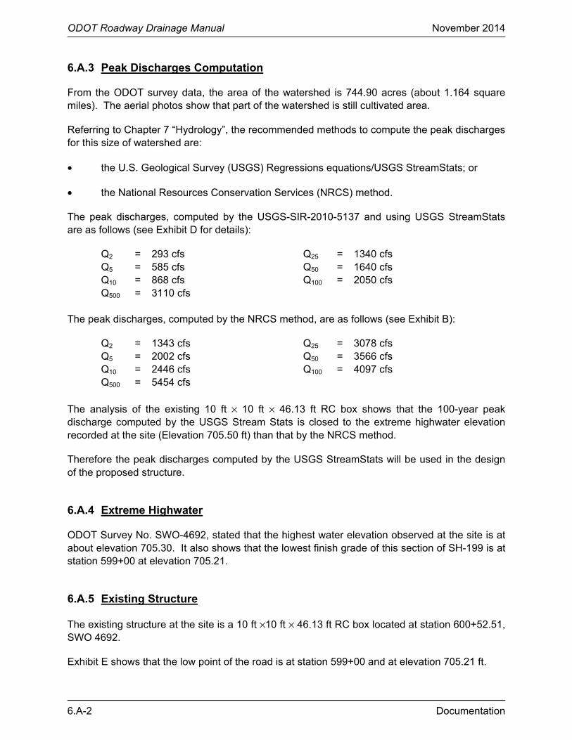
6.A.3 Peak Discharges Computation
From the ODOT survey data, the area of the watershed is 744.90 acres (about 1.164 square miles). The aerial photos show that part of the watershed is still cultivated area.
Referring to Chapter 7 “Hydrology”, the recommended methods to compute the peak discharges for this size of watershed are:
• the U.S. Geological Survey (USGS) Regressions equations/USGS StreamStats; or
• the National Resources Conservation Services (NRCS) method.
The peak discharges, computed by the USGS-SIR-2010-5137 and using USGS StreamStats are as follows (see Exhibit D for details):
Q2 = 293 cfs Q25 = 1340 cfs Q5 = 585 cfs Q50 = 1640 cfs Q10 = 868 cfs Q100 = 2050 cfs Q500 = 3110 cfs
The peak discharges, computed by the NRCS method, are as follows (see Exhibit B):
Q2 = 1343 cfs Q25 = 3078 cfs Q5 = 2002 cfs Q50 = 3566 cfs Q10 = 2446 cfs Q100 = 4097 cfs Q500 = 5454 cfs
The analysis of the existing 10 ft × 10 ft × 46.13 ft RC box shows that the 100-year peak discharge computed by the USGS Stream Stats is closed to the extreme highwater elevation recorded at the site (Elevation 705.50 ft) than that by the NRCS method.
Therefore the peak discharges computed by the USGS StreamStats will be used in the design of the proposed structure.
6.A.4 Extreme Highwater
ODOT Survey No. SWO-4692, stated that the highest water elevation observed at the site is at about elevation 705.30. It also shows that the lowest finish grade of this section of SH-199 is at station 599+00 at elevation 705.21.
6.A.5 Existing Structure
The existing structure at the site is a 10 ft ×10 ft × 46.13 ft RC box located at station 600+52.51, SWO 4692.
Exhibit E shows that the low point of the road is at station 599+00 and at elevation 705.21 ft.
ODOT Roadway Drainage Manual November 2014
Documentation 6.A-3
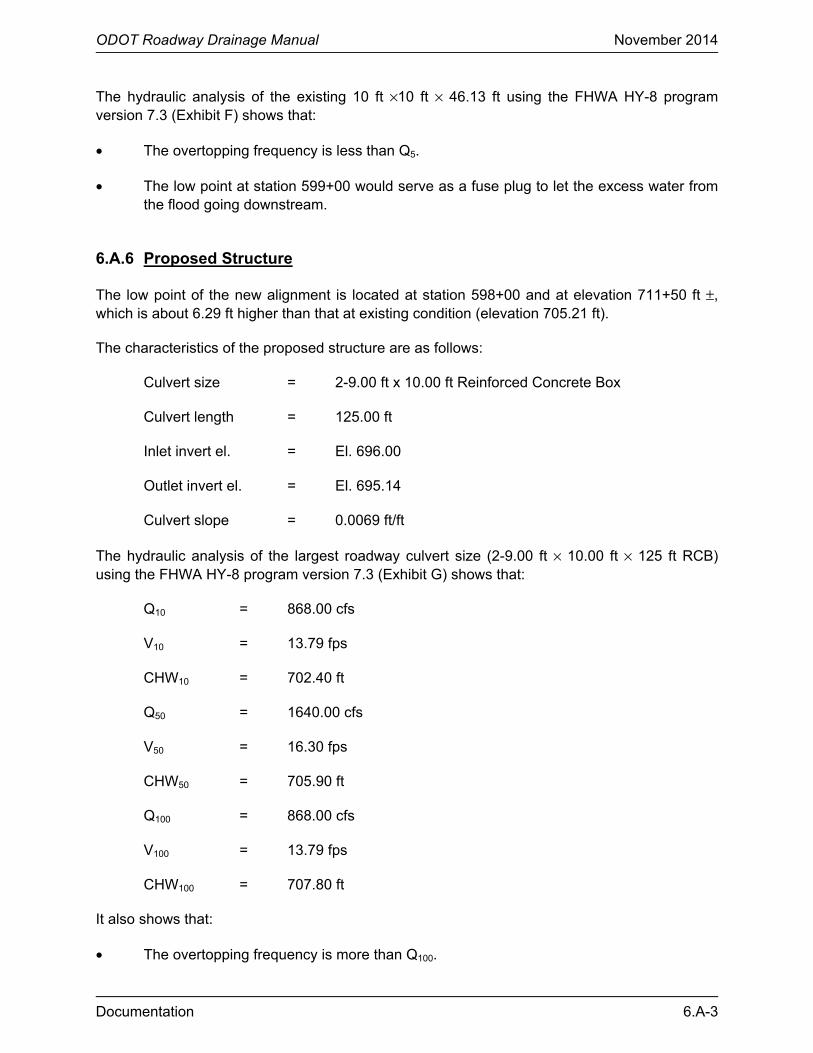
The hydraulic analysis of the existing 10 ft ×10 ft × 46.13 ft using the FHWA HY-8 program version 7.3 (Exhibit F) shows that:
• The overtopping frequency is less than Q5.
• The low point at station 599+00 would serve as a fuse plug to let the excess water from the flood going downstream.
6.A.6 Proposed Structure
The low point of the new alignment is located at station 598+00 and at elevation 711+50 ft ±, which is about 6.29 ft higher than that at existing condition (elevation 705.21 ft).
The characteristics of the proposed structure are as follows:
Culvert size = 2-9.00 ft x 10.00 ft Reinforced Concrete Box
Culvert length = 125.00 ft
Inlet invert el. = El. 696.00
Outlet invert el. = El. 695.14
Culvert slope = 0.0069 ft/ft
The hydraulic analysis of the largest roadway culvert size (2-9.00 ft × 10.00 ft × 125 ft RCB) using the FHWA HY-8 program version 7.3 (Exhibit G) shows that:
Q10 = 868.00 cfs
V10 = 13.79 fps
CHW10 = 702.40 ft
Q50 = 1640.00 cfs
V50 = 16.30 fps
CHW50 = 705.90 ft
Q100 = 868.00 cfs
V100 = 13.79 fps
CHW100 = 707.80 ft
It also shows that:
• The overtopping frequency is more than Q100.
ODOT Roadway Drainage Manual November 2014
6.A-4 Documentation
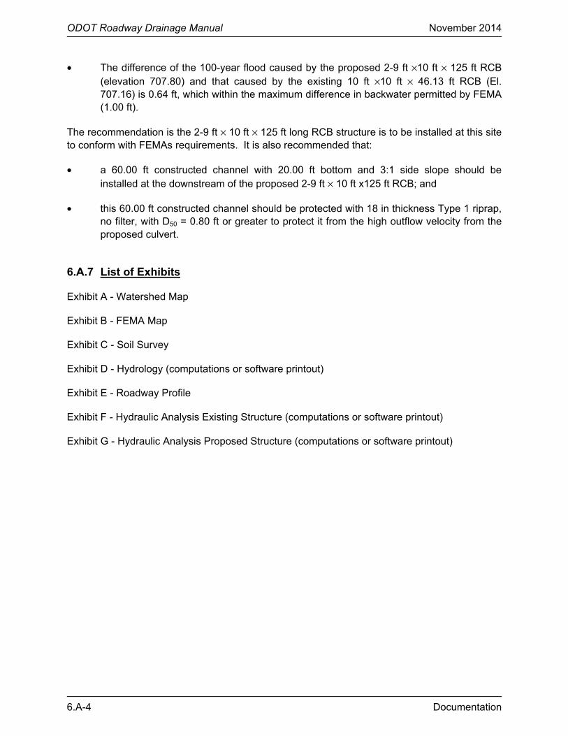
• The difference of the 100-year flood caused by the proposed 2-9 ft ×10 ft × 125 ft RCB (elevation 707.80) and that caused by the existing 10 ft ×10 ft × 46.13 ft RCB (El. 707.16) is 0.64 ft, which within the maximum difference in backwater permitted by FEMA (1.00 ft).
The recommendation is the 2-9 ft × 10 ft × 125 ft long RCB structure is to be installed at this site to conform with FEMAs requirements. It is also recommended that:
• a 60.00 ft constructed channel with 20.00 ft bottom and 3:1 side slope should be installed at the downstream of the proposed 2-9 ft × 10 ft x125 ft RCB; and
• this 60.00 ft constructed channel should be protected with 18 in thickness Type 1 riprap, no filter, with D50 = 0.80 ft or greater to protect it from the high outflow velocity from the proposed culvert.
6.A.7 List of Exhibits
Exhibit A - Watershed Map
Exhibit B - FEMA Map
Exhibit C - Soil Survey
Exhibit D - Hydrology (computations or software printout)
Exhibit E - Roadway Profile
Exhibit F - Hydraulic Analysis Existing Structure (computations or software printout)
Exhibit G - Hydraulic Analysis Proposed Structure (computations or software printout)