Embed Size (px)
Citation preview
t . . NASA Technical Memorandum
NASA TM - 86594
. . L
I
CHARACTERIZATION AND HARDWARE MODIFICATION OF LINEAR MOMENTUM EXCHANGE DEVICES
George D. Edgemon, Sally Curtis, and Henry B. Waites
Siruciures and Dyriamics iaboraiory Science and Engineering Directorate
March 1987
https://ntrs.nasa.gov/search.jsp?R=19870015290 2018-09-08T21:02:03+00:00Z
1. REPORT NO. 2. GOVERNMNT ACCESSION NO.
NASA TM-86594 4. T I T L E AND SUBTITLE
Characterization and Hardware Modification of Linear Momentum Exchange Devices
7. AUTHOR(S)
-- George D. Edgemon," Sally Curtis," and Henry B. Waites 9. PERFORMING ORGANIZATION NAME AND ADDRESS
George C. Marshall Space Flight Center Marshall Space Flight Center, Alabama 358 I2
12. SPONSORING AGENCY NAME AND ADDRESS
National Aeronautics and Space Administration Washington, D.C. 20546
3. R E C I P E N T ' S CATALOG NO.
5. REPORT DATE March 1987
r
6. PERFORMING ORGANIZATION CODE
8 . PERFORMING ORGANIZATION REPOR r t
- 10. WORK UNIT NO.
1 1 . CONTRACT OR GRANT NO.
13. TYPE OF REP0R-i (t PERIOD COVERE' - Technical Memorandum
1.3. SPONSORING AGENCY CODE
I I 1 5 . SUPPLEMENTARY NOTES
Prepared by Structures and Dynamics Laboratory, Science and Engineering Directorate. "Control Dynamics Co., Suite 304, 600 Blvd. South, Huntsville, Alabama 35802.
I
16. ABSTRACT
A sequence of modifications were made on the TRW Linear Momentum Exchange Devices (LMEDs) which were supplied for a joint MSFC/Air Force Wright Aeronautical Laboratory (AFWAL) control venture called Vibrational Control of Space Structures (VCOSS)-II. The mod- ifications were necessary 40 alleviate and assuage the LMED nonlinearities. Extensive discussion of the LMED modifications are presented along with the test pian, test results and conclusions. In addi- tion, a chronology of events, relative to the LMED changes, is contained in the paper.
17. KEY WORDS
Linear Momentum Exchange Devices Active Vibration Suppression
I
i I I I 1
18. D l STRl BUT ION STATEMENT
Unclassified - Unlimited
TABLE OF CONTENTS
Page
I . INTRODUCTION ....................................................................................... 1
11. DISCUSSIONOF HARDWAREMODIFICATIONS .............................................. 1
111. TESTING ................................................................................................. 2 t
IV. TEST RESULTS ......................................................................................... 3
V. CONCLUSIONS ......................................................................................... 3
APPENDIX: MODIFICATION HISTORY .......................................................... 37
iii
LIST OF ILLUSTRATIONS
Figure
I .
2.
3.
4.
5 .
6.
7.
8.
9.
10.
1 1 .
12.
13.
14.
15.
16.
17.
18.
19.
20.
Title Page
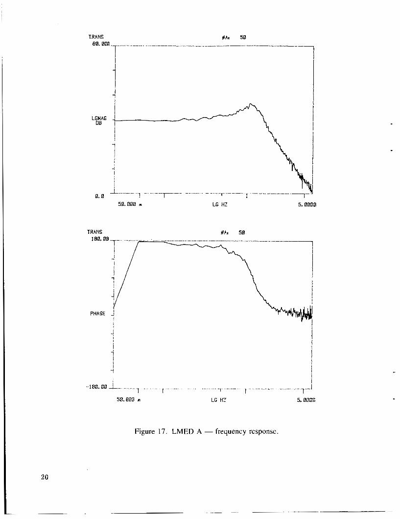
LMED A - frequency response ................................................................. 4
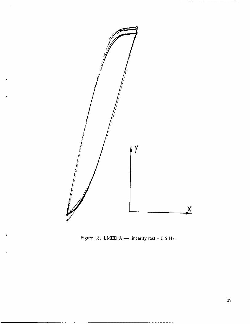
LMED A - linearity test - 0.5 Hz ...............................................................
LMED A - linearity test -0.25 Hz.. ............................................................
5
6 -
............................................................... LMED A - linearity test - 0.1 Hz 7
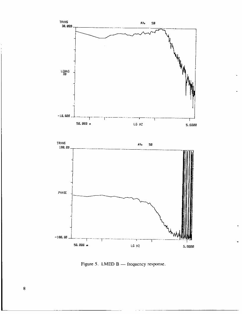
................................................................ LMED B -frequency response.. 8
............................................................... LMED B - linearity test - 0.5 Hz
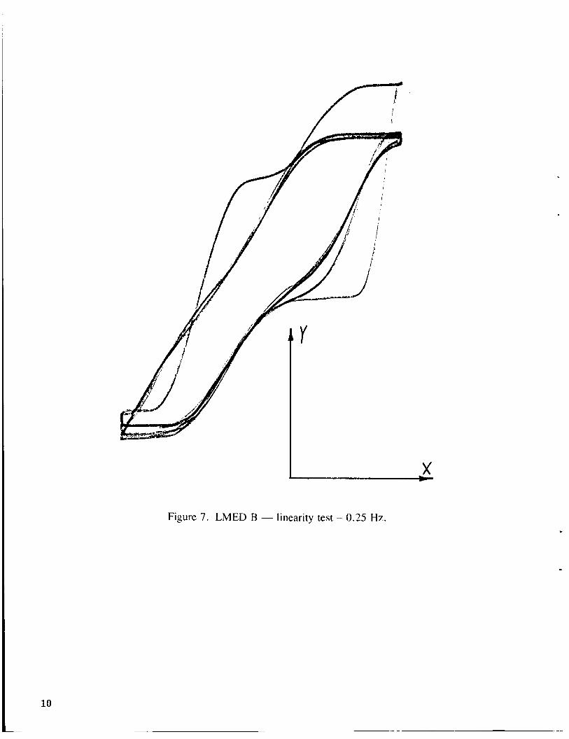
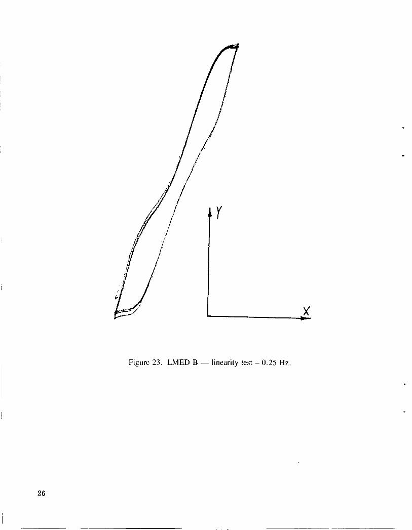
LMED B - linearity test - 0.25 Hz
9
10 ..............................................................
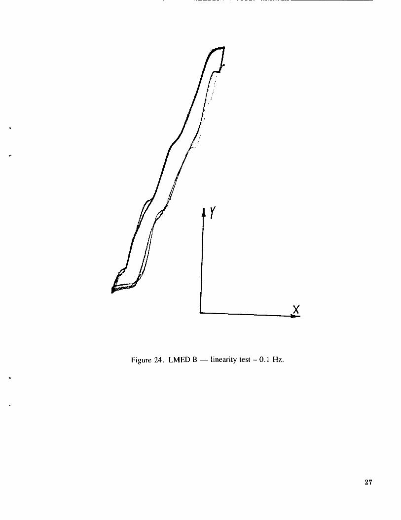
LMED B -linearity test - 0.1 Hz ............................................................... 1 1
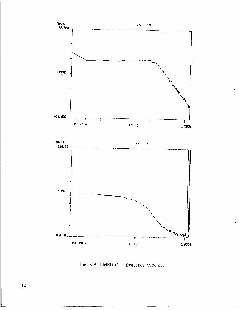
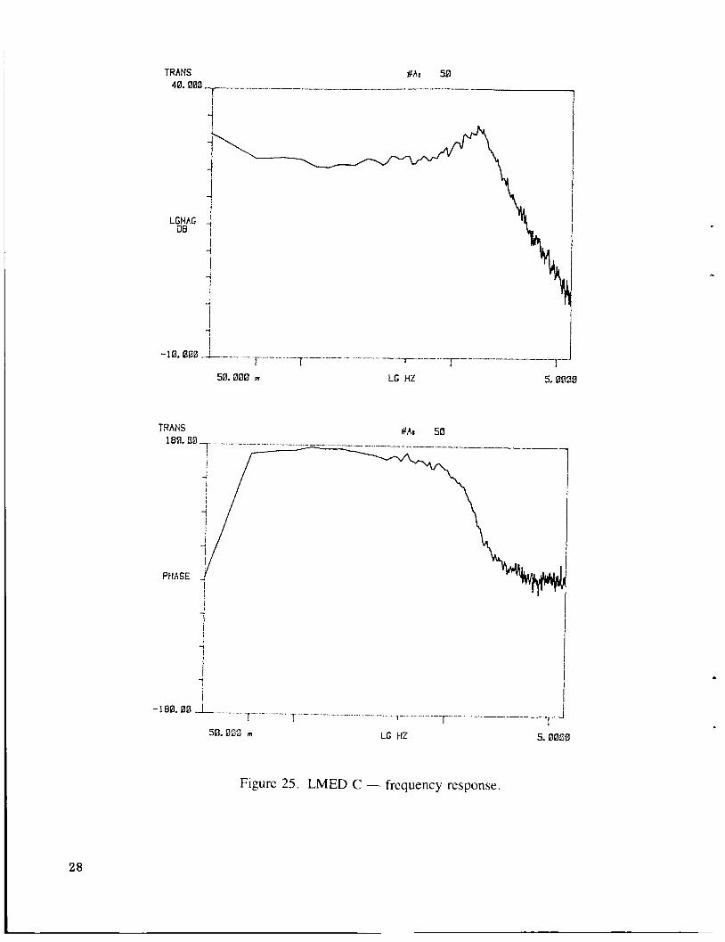
................................................................ LMED C - frequency response.. 12
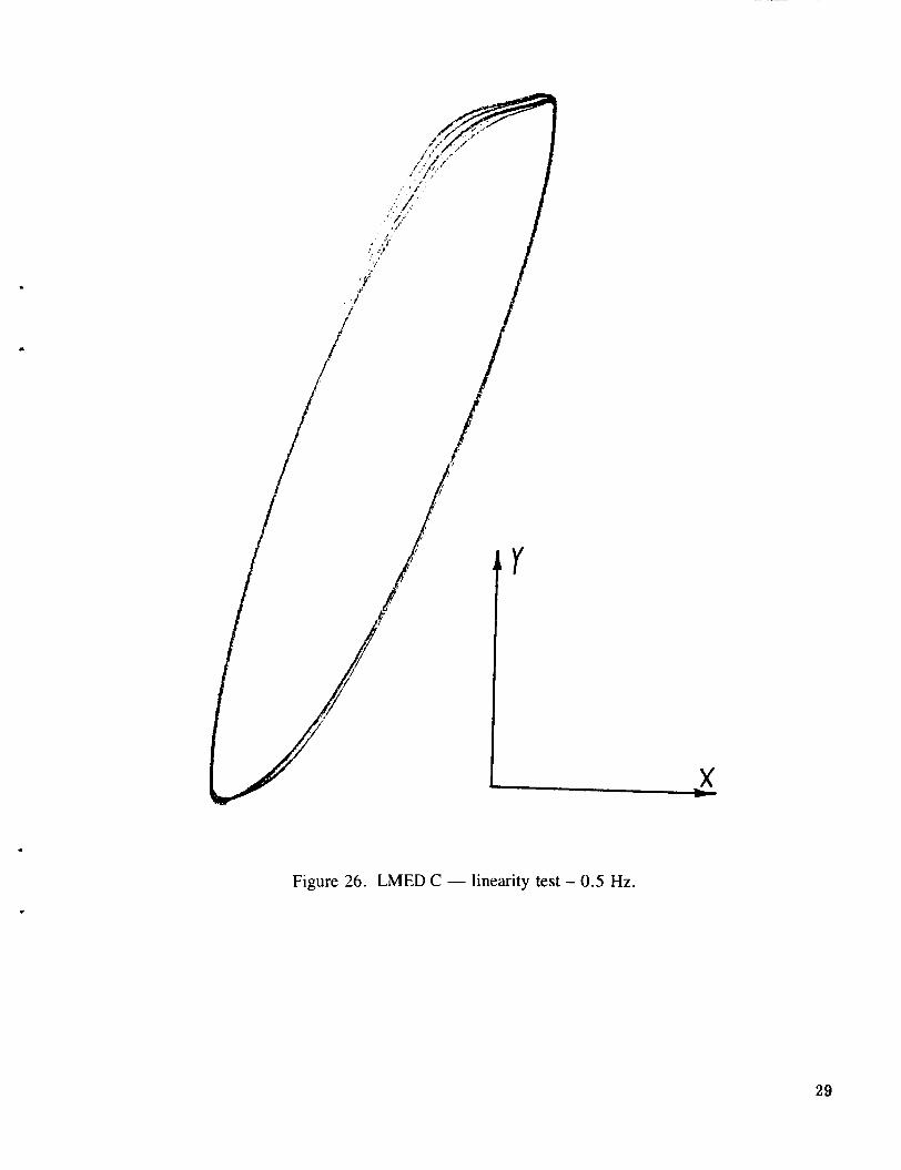
............................................................... LMED C - linearity test - 0.5 Hz 13
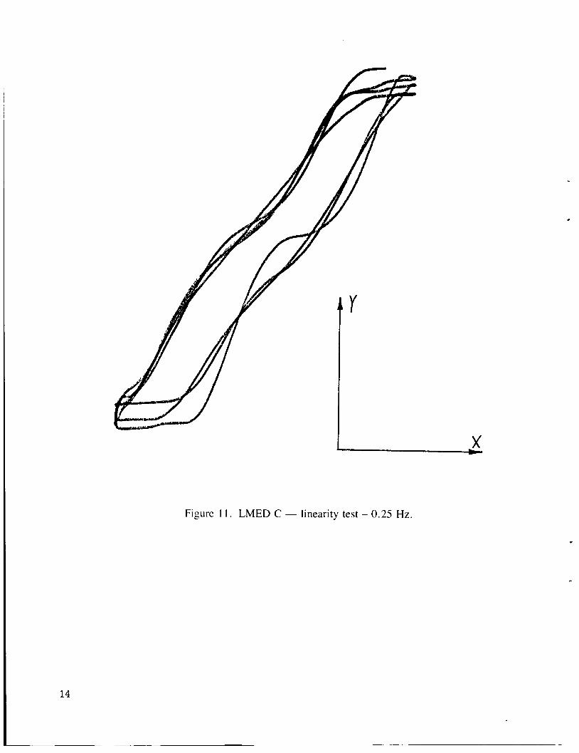
14 .............................................................. LMED C - linearity test - 0.25 Hz
............................................................... LMED C - linearity test - 0.1 Hz 15
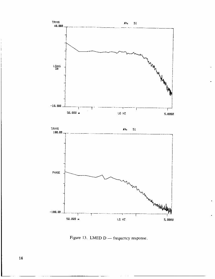
................................................................. LMED D - frequency response 16
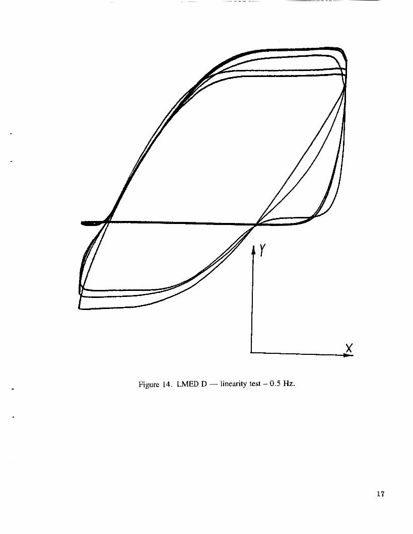
LMED D - linearity test -0.5 Hz ...............................................................
LMEDD-linearity test-0.25 Hz .............................................................. 18
17
............................................................... LMED D - linearity test - 0.1 Hz
LMED A -frequency response .................................................................
19
20 b
LMED A -linearity test - 0.5 Hz ...............................................................
LMED A - linearity test -0.25 Hz., ............................................................
2 1
22
LMED A - linearity test - 0.1 Hz ............................................................... 23
iv
LIST OF ILLUSTRATIONS (Concluded)
Figure
21 .
22 .
23 .
25 .
26 .
27 .
28 .
29 .
30 .
31 .
32 .
Title
LM ED B . frequency response ..................................................................
LMED B-linearity test-0.5 Hz ...............................................................
LMED B-linearity test-0.25 Hz ..............................................................
LMED B- linearity test.0 . I Hz ...............................................................
LMED C - frequency response .......... , .......................................................
LMEDC-linearity test-0.5 Hz ...............................................................
LMEDC-linearity test-0.25 Hz ..............................................................
LMEDC-linearitytest.0 . I Hz ...............................................................
LMED D - frequency response .................................................................
LMED D- linearity test . 0.5 Hz ................................................................
LMEDD-linearitytest-0.25 Hz ..............................................................
LMEDD-linearitytest-0.1 Hz ...............................................................
Page
24
25
26
27
28
29
30
31
32
33
34
35
8
V
TECHNICAL MEMORANDUM
e
CHARACTERIZATION AND HARDWARE MODIFICATION OF LINEAR MOMENTUM EXCHANGE DEVICES
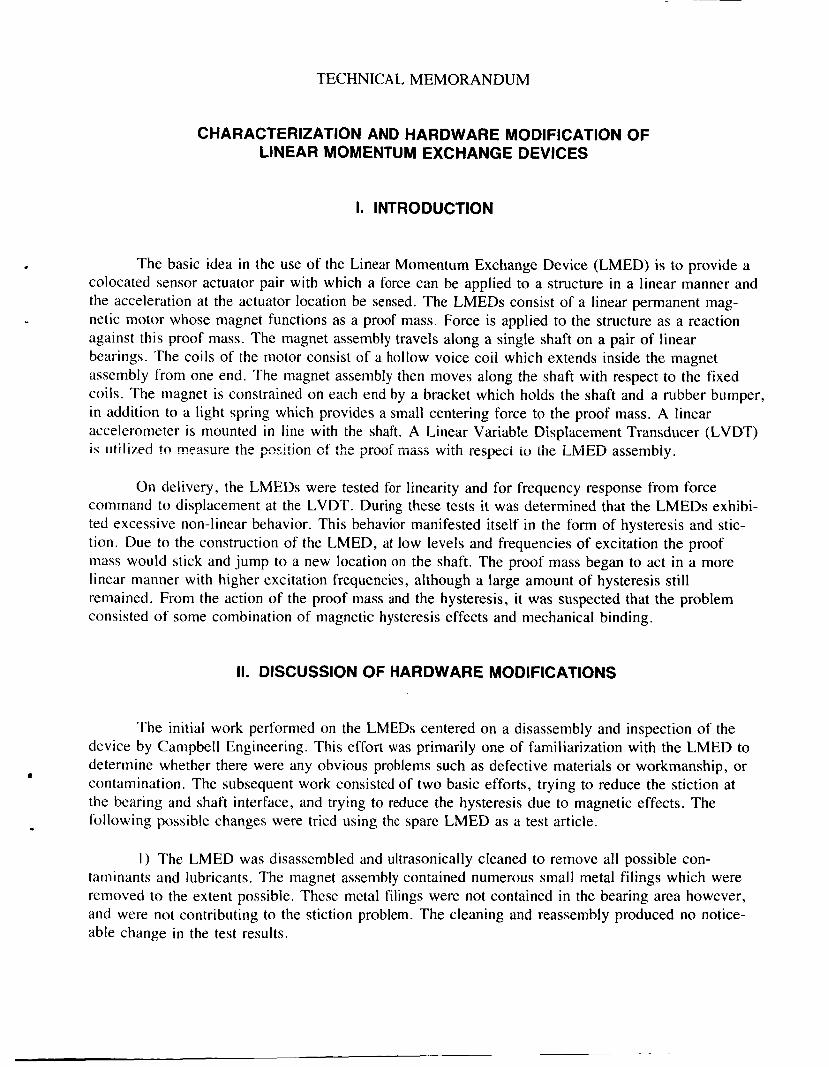
I. INTRODUCTION
The basic idea in the use of the Linear Momentum Exchange Device (LMED) is to provide a colocated sensor actuator pair with which a force can be applied to a structure in a linear manner and the acceleration at the actuator location be sensed. The LMEDs consist of a linear permanent mag- netic motor whose magnet functions as a proof mass. Force is applied to the structure as a reaction against this proof mass. The magnet assembly travels along a single shaft on a pair of linear bearings. The coils of the motor consist of a hollow voice coil which extends inside the magnet assembly from one end. The magnet assembly then moves along the shaft with respect to the fixed coils. The magnet is constrained on each end by a bracket which holds the shaft and a rubber bumper, in addition to a light spring which provides a small centering force to the proof mass. A linear accelerometer is mounted in line with the shaft. A Linear Variable Displacement Transducer (LVDT) i s iitili7eCI tn measure the p~sltic:: cf the i;i-c;of mass with ~especi io ihe LIVICD assembiy. r . .- . .
On delivery, the LMEDs were tested for linearity and for frequency response from force command to displacement at the LVDT. During these tests it was determined that the LMEDs exhibi- ted excessive non-linear behavior. This behavior manifested itself in the form of hysteresis and stic- tion. Due to the construction of the LMED, at low levels and frequencies of excitation the proof mass would stick and jump to a new location on the shaft. The proof mass began to act in a more linear manner with higher excitation frequencies, although a large amount of hysteresis still remained. From the action of the proof mass and the hysteresis, it was suspected that the problem consisted of some combination of magnetic hysteresis effects and mechanical binding.
II. DISCUSSION OF HARDWARE MODIFICATIONS
The initial work performed on the LMEDs centered on a disassembly and inspection of the device by Campbell Engineering. This effort was primarily one of familiarization with the LMED to determine whether there were any obvious problems such as defective materials or workmanship, or contamination. The subsequent work consisted of two basic efforts, trying to reduce the stiction at the bearing and shaft interface, and trying to reduce the hysteresis due to magnetic effects. The following possible changes were tried using the spare LMED as a test article.
I ) The LMED was disassembled and ultrasonically cleaned to remove all possible con- taminants and lubricants. The magnet assembly contained numerous small metal filings which were removed to the extent possible. These metal filings were not contained in the bearing area however, and were not contributing to the stiction problem. The cleaning and reassembly produced no notice- able change in the test results.
2) The LVDT consists of a cylindrical transformer housing and a long core with which the displacement of the proof mass is measured. The core extends into the LVDT housing and is attached to the proof mass with an arm. It was determined that the drag of the LVDT core in the housing could significantly increase the stiction, thus necessitating careful alignment of the core to eliminate binding. Subsequent tests indicated that even with the LVDT core completely disconnected, the proof mass was still visibly sticking as it had in previous tests.
3) The linear bearings were oiled with a light machine oil and the LMED was retested. Lubrication of the bearings did not change the behavior of the LMED. .
4) The shaft supplied with the LMED was strongly magnetized and this contributed to the hysteresis observed in the tests. It was noted while the LMED was disassembled, that the magnetism of the shaft was sufficiently strong to retain the shaft in the magnet even when held vertically. When- displaced and released, the shaft returned strongly to the center of the magnet. A low magnetism stainless steel shaft was produced by MSFC and tested with no change in the observed stiction. The hysteresis was reduced somewhat although the shaft was still noticeably magnetized.
5 ) Various types of replacement bearings were tried to determine if the bearings supplied were simply not of the best quality. An instrument grade bearing was obtained from Thompson Bear- ing Co. which significantly reduced the stiction effect. The various bearings all cohained chrome steel balls which displayed a propensity to bind together due to operating inside a strong magnetic field. The instrument grade bearings, with its closer manufacturing tolerances, seem to be the best available linear bearing and are a direct replacement for the supplied bearings. The performance of the bearing could be improved somewhat through the use of a non-magnetic ball if a ball of suffi- ciently hard material was utilized. Several materials were considered, such as nylon and beryllium, but were judged too soft to provide reasonable performance and wear characteristics.
6) An aluminum shaft was built by Speedring to reduce hysteresis due to magnetism. The shaft was hard anodized to a surface hardness of Rockwell 60 and was lapped to a 4 micron or better surface finish. This surface finish was chosen to reduce stiction at the shaft and ball interface due to surface roughness. The shaft is consistent in tolerances with the specifications given by Thompson Bearing Co. for the instrument grade bearing. This shaft significantly reduced the magnetic hysteresis and in combination with the Thompson instrument grade bearing produced the lowest level of stiction observed.
LMEDs A through D were modified to include the instrument grade bearings and the hard anodized aluminum shaft. These LMEDs were each tested before and after modification.
A history of the steps taken in the hardware modification study is included in the appendix.
111. TESTING
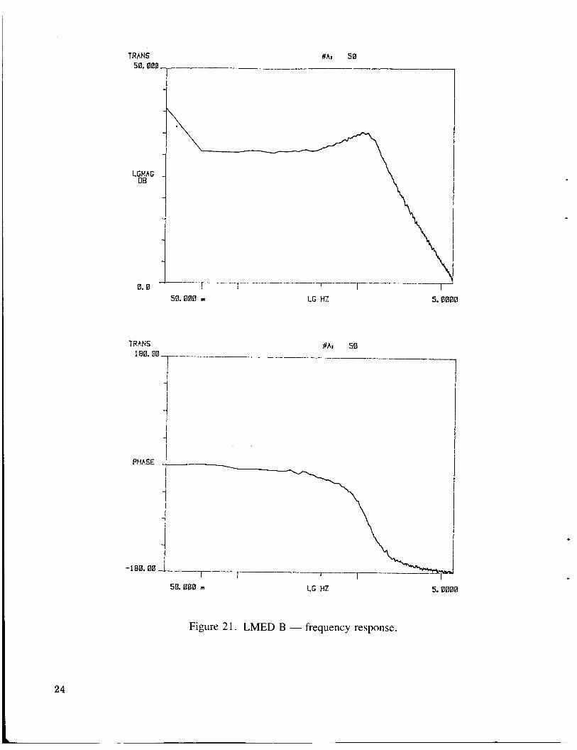
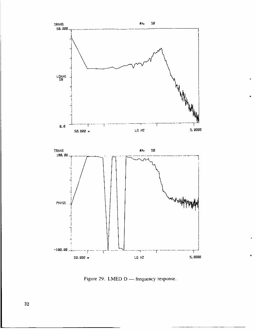
The study of the LMED characteristics utilized frequency response and linearity tests. The frequency response tests were obtained with a spectrum analyzer using a “white noise” input to drive
2
L ~
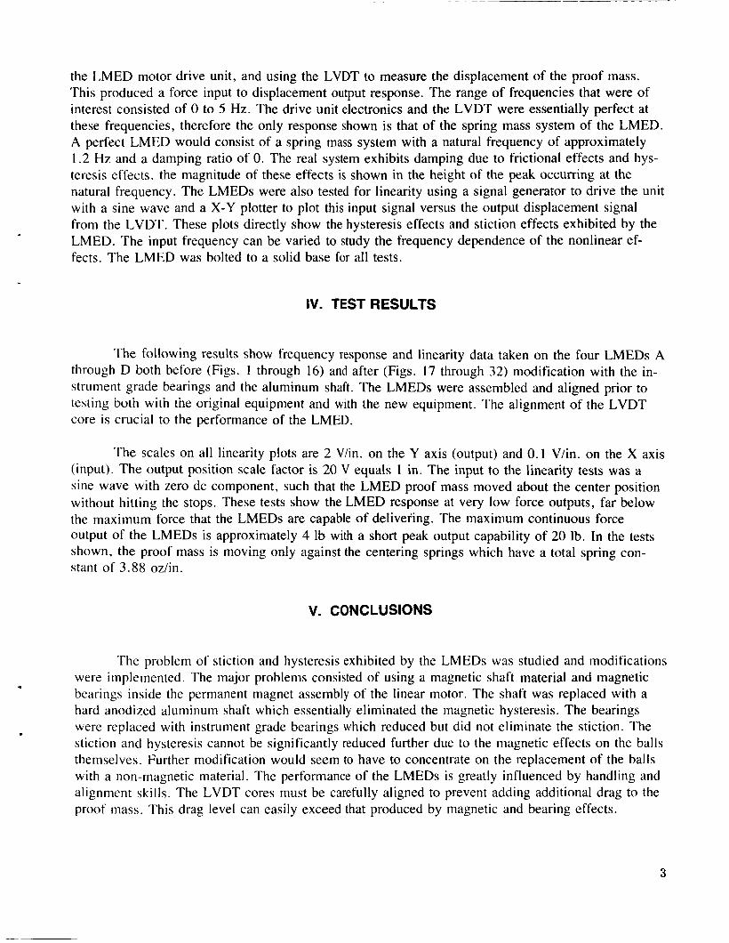
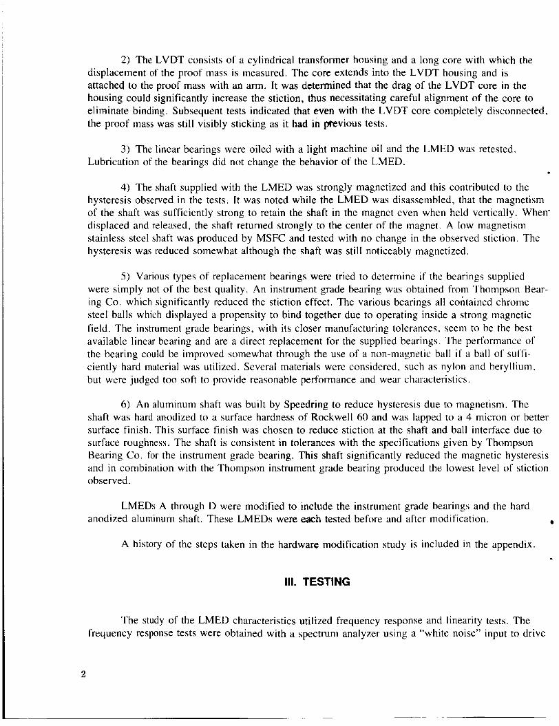
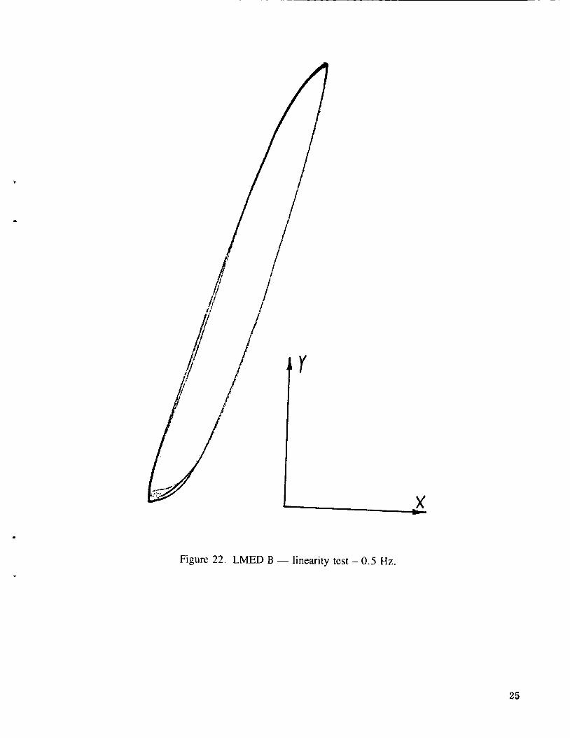
the LMED motor drive unit, and using the LVDT to measure the displacement of the proof mass. This produced a force input to displacement output response. The range of frequencies that were of interest consisted of 0 to 5 Hz. The drive unit electronics and the LVDT were essentially perfect at these frequencies, therefore the only response shown is that of the spring mass system of the LMED. A perfect LMED would consist of a spring mass system with a natural frequency of approximately 1.2 Hz and a damping ratio of 0. The real system exhibits damping due to frictional effects and hys- teresis effects. the magnitude of these effects is shown in the height of the peak occurring at the natural frequency. The LMEDs were also tested for linearity using a signal generator to drive the unit with a sine wave and a X-Y plotter to plot this input signal versus the output displacement signal from the LVDT. These plots directly show the hysteresis effects and stiction effects exhibited by the LMED. The input frequency can be varied to study the frequency dependence of the nonlinear ef- fects. The LMED was bolted to a solid base for all tests.
IV. TEST RESULTS
The following results show frequency response and linearity data taken on the four LMEDs A through D both before (Figs. 1 through 16) and after (Figs. 17 through 32) modification with the in- strument grade bearings and the aluminum shaft. The LMEDs were assembled and aligned prior to testing both wir'n the original equipment and with the new equipment. The alignment of the LVDT core is crucial to the performance of the LMED.
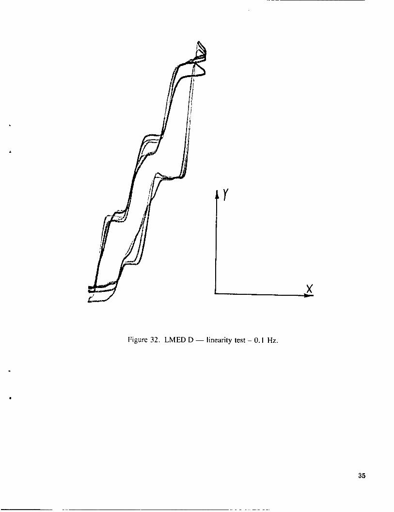
The scales on all linearity plots are 2 Vlin. on the Y axis (output) and 0.1 V/in. on the X axis (input). The output position scale factor is 20 V equals 1 in. The input to the linearity tests was a sine wave with zero dc component, such that the LMED proof mass moved about the center position without hitting the stops. These tests show the LMED response at very low force outputs, far below the maximum force that the LMEDs are capable of delivering. The maximum continuous force output of the LMEDs is approximately 4 Ib with a short peak output capability of 20 Ib. In the tests shown, the proof mass is moving only against the centering springs which have a total spring con- stant of 3.88 oz/in.
V. CONCLUSIONS
The problem of stiction and hysteresis exhibited by the LMEDs was studied and modifications were implemented. The major problems consisted of using a magnetic shaft material and magnetic bearings inside the permanent magnet assembly of the linear motor. The shaft was replaced with a hard anodized aluminum shaft which essentially eliminated the magnetic hysteresis. The bearings were replaced with instrument grade bearings which reduced but did not eliminate the stiction. The stiction and hysteresis cannot be significantly reduced further due to the magnetic effects on the balls themselves. Further modification would seem to have to concentrate on the replacement of the balls with a non-magnetic material. The performance of the LMEDs is greatly influenced by handling and alignment skills. The LVDT cores must be carefully aligned to prevent adding additional drag to the proof mass. This drag level can easily exceed that produced by magnetic and bearing effects.
3
4
1- -19 .EBE - L -.,-
LG Hi! 5.0000 50.000 m
TRANS
,
#A: 50
LG tP 5.0800
Figure 1 . LMED A - frequency response.
Figure 2. LMED A - linearity test - 0.5 Hz. .
5
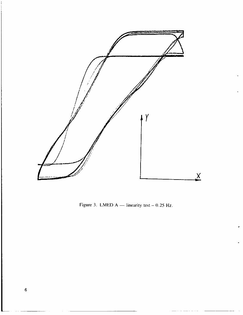
Figure 3 . LMED A - linearity test - 0.25 Hz.
6
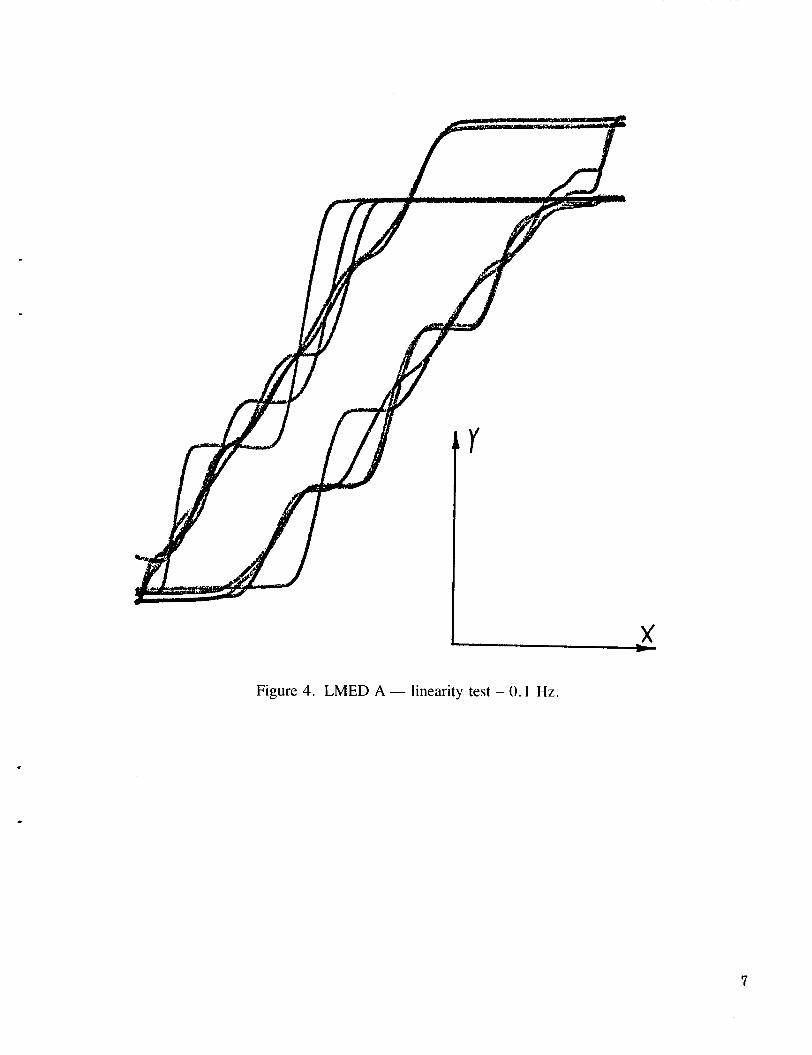
Figure 4. LMED A - linearity test - 0.1 Hz.
7
TRANS 30.000
RAI 50
LGMAG DE
-10.000 -
50.000 m LG HZ 5. QQ00
TRhNS #AI 50
1 ---1-- - ---__ 1T' FU 7 -
50.ElBQ m LG HZ 5.0000
-180. 00 ~ . . ' - ~ ._I.__-__X__._.____ .
Figure 5 . LMED B - frequency response.
8
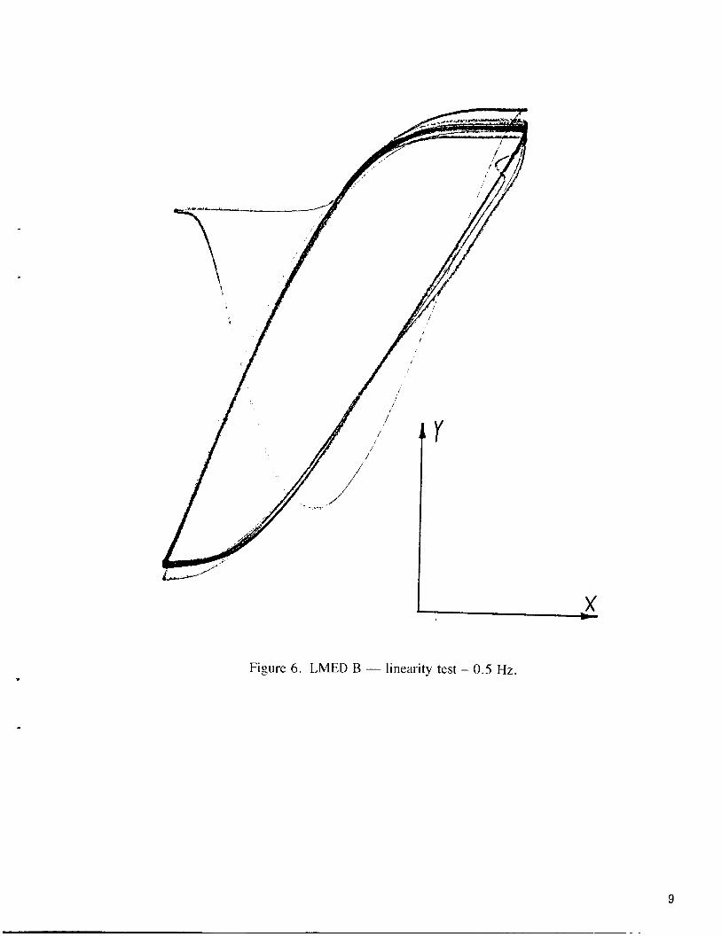
Figure 6. LMED B - linearity test - 0.5 Hz.
9
r
x
Figure 7. LMED B - linearity test - 0.25 Hz. .
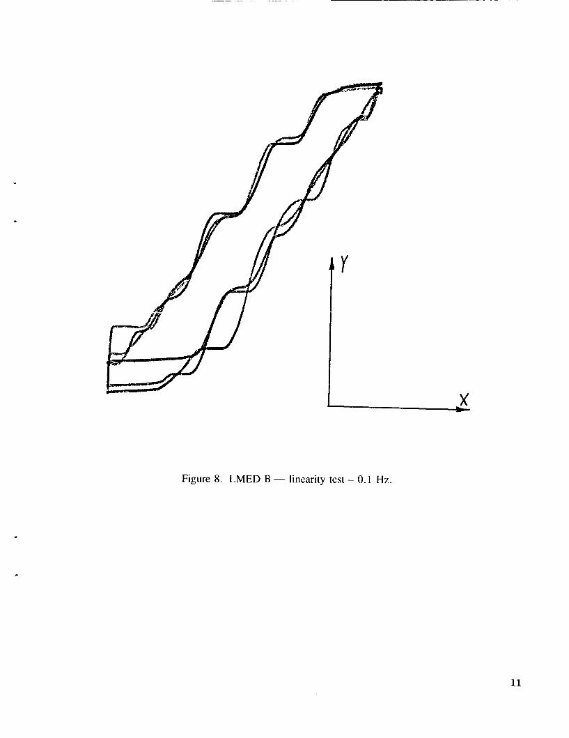
Figure 8. LMED B - linearity test - 0.1 Hz.
11
12
TRANS UAI 50 . - ~ ~ _ _ _ - 50. E00
-1 0. 000
LG HZ 5.0000 50.000 m
LC HZ 5.0080 50.000 m
Figure 9. LMED C - frequency response.
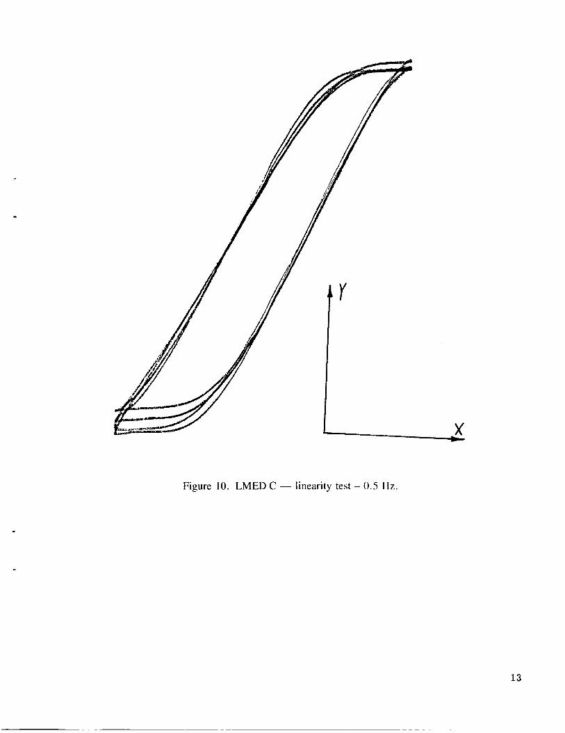
Figure 10. LMED C - linearity test - 0.5 l i z .
13
c
Figure 1 1 . LMED C - linearity test - 0.25 Hz.
c
14
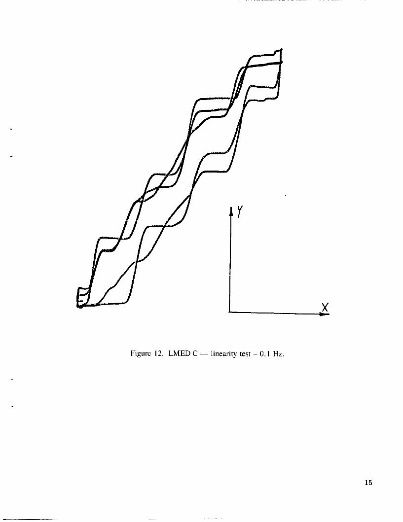
Figure 12. LMED C - linearity test - 0. I Hz.
15
1
LG HZ 5.0000
Figure 13. LMED D - frequency response.
I x
Figure 14. LMED D - linearity test - 0.5 Hz.
17
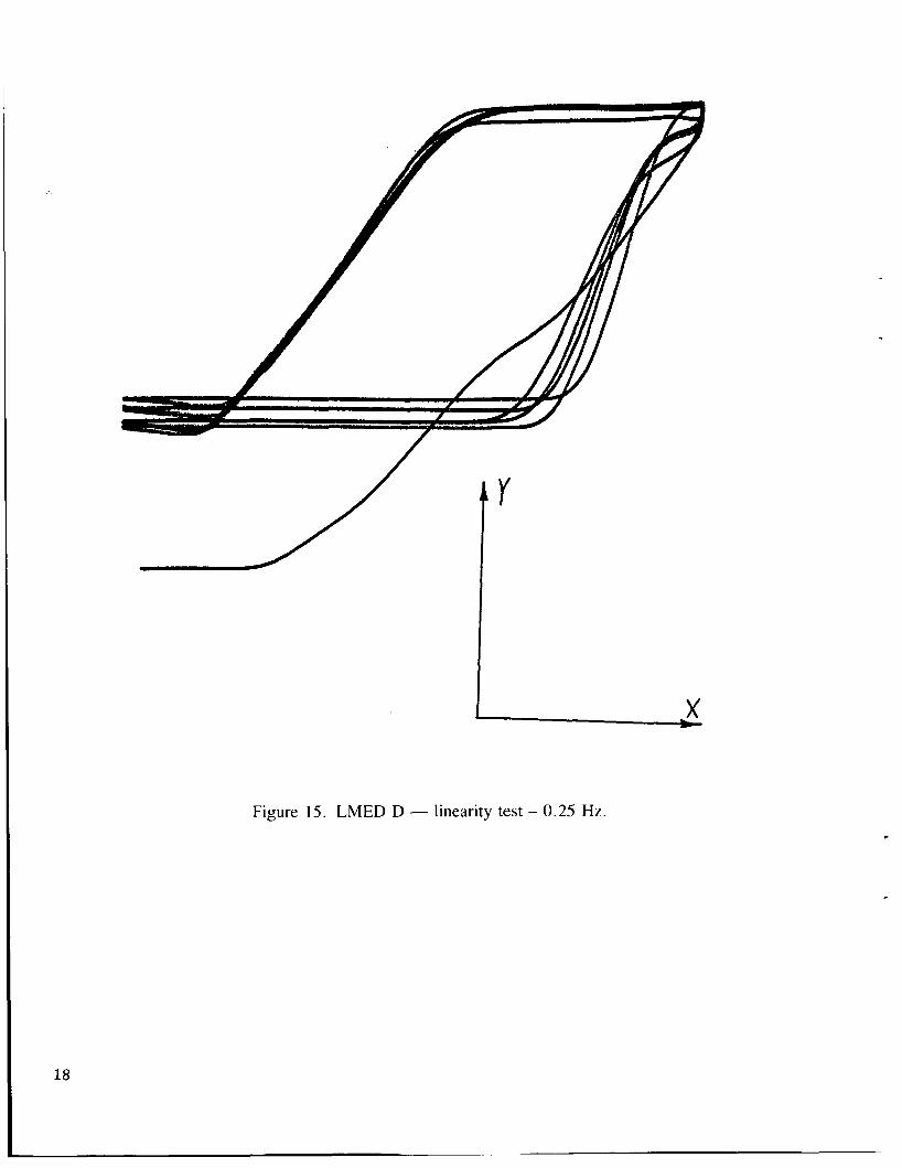
Figure 15. LMED D - linearity test - 0.25 Hz.
18
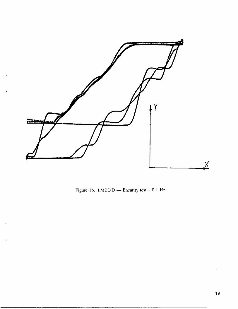
Figure 16. LMED D - linearity test - 0. I Hz.
19
TRANS NA; 50 - 60.000. - .---_
T I I 1 i i
7
50.DB0 m LG HZ 5. 0B00
i -,.- - - 1 1 .-
50.0Q!iI m LC H7 5.0mE)
. . . . . . -. . . . -1acI. 00 L-.. ,.. __. ...._ , ._ __
Figure 17. LMED A - frequency response.
.
Figure 18. LMED A - linearity test - 0.5 Hz.
21
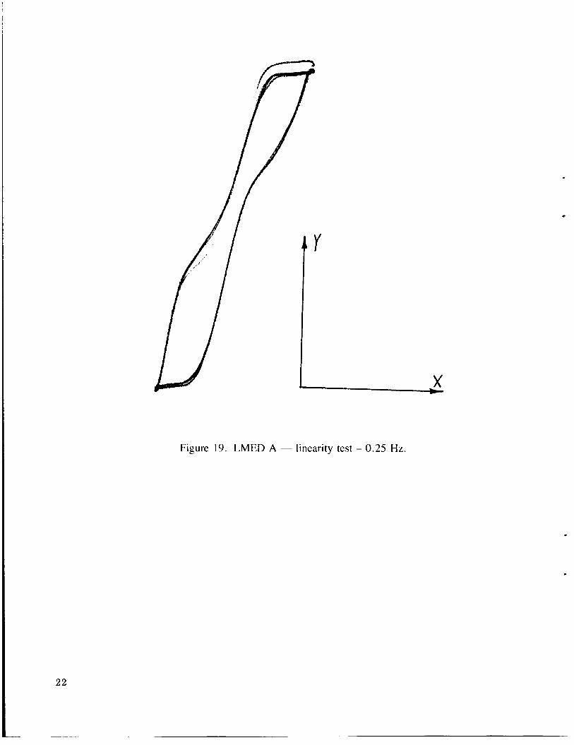
Figure 19. LMED A - linearity test - 0.25 Hz.
22
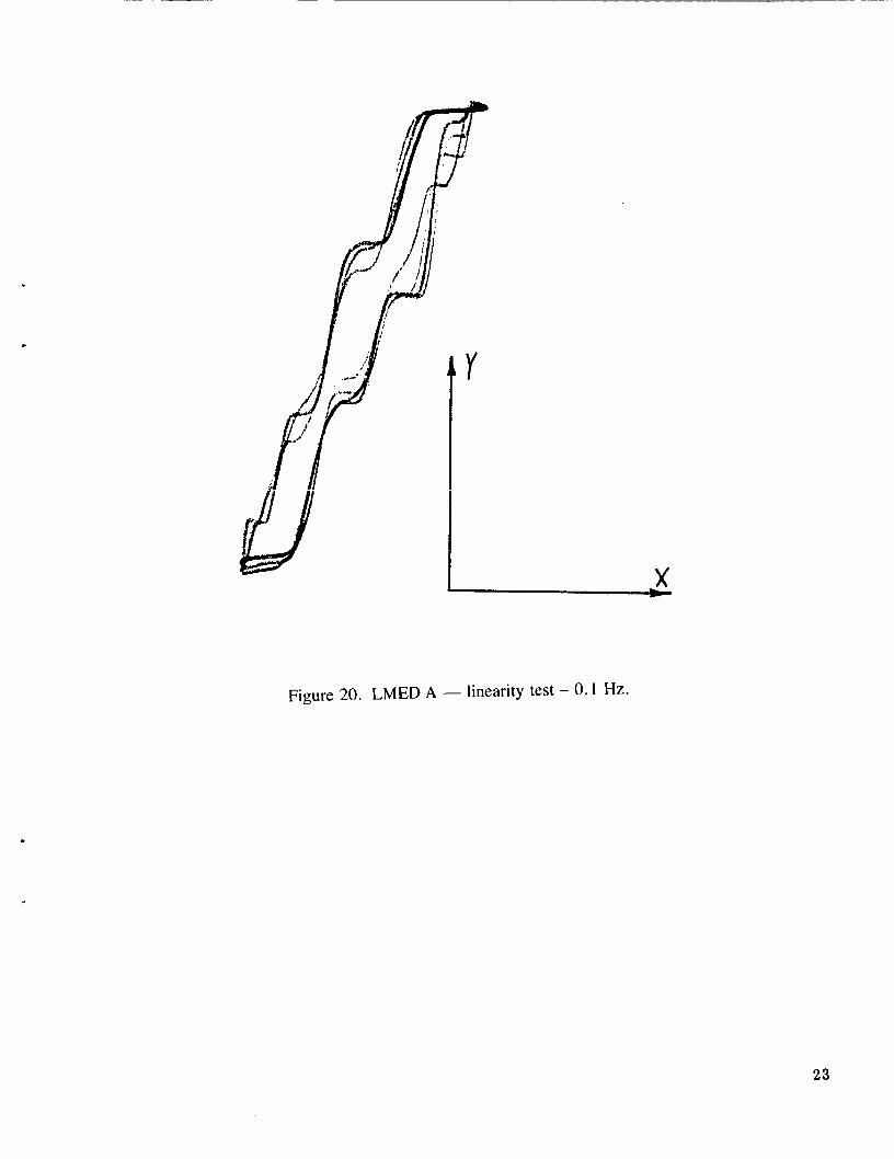
Figure 20. LMED A - linearity test - 0.1 Hz.
23
TRANS #A: 50 -~ -_ --
000 1--
\
50.GIOR m LG HZ 5. BBDD
24
.
. Figure 22. LMED B - linearity test - 0.5 Hz.
25
.
x
Figure 23. LMED B - linearity test - 0.25 Hz.
.
26
.
Figure 24. LMED B - linearity test - 0. I Hz.
27
TRANS HAI 5D 40. BB3 ~ __ ______
T i
i I -I I
LGMAG ilB 1
I -I I
j 1 I
1
.
LG HZ
Figure 25. LMED C - frequency response.
28
c
i
Figure 26. LMED C - linearity test - 0.5 Hz.
29
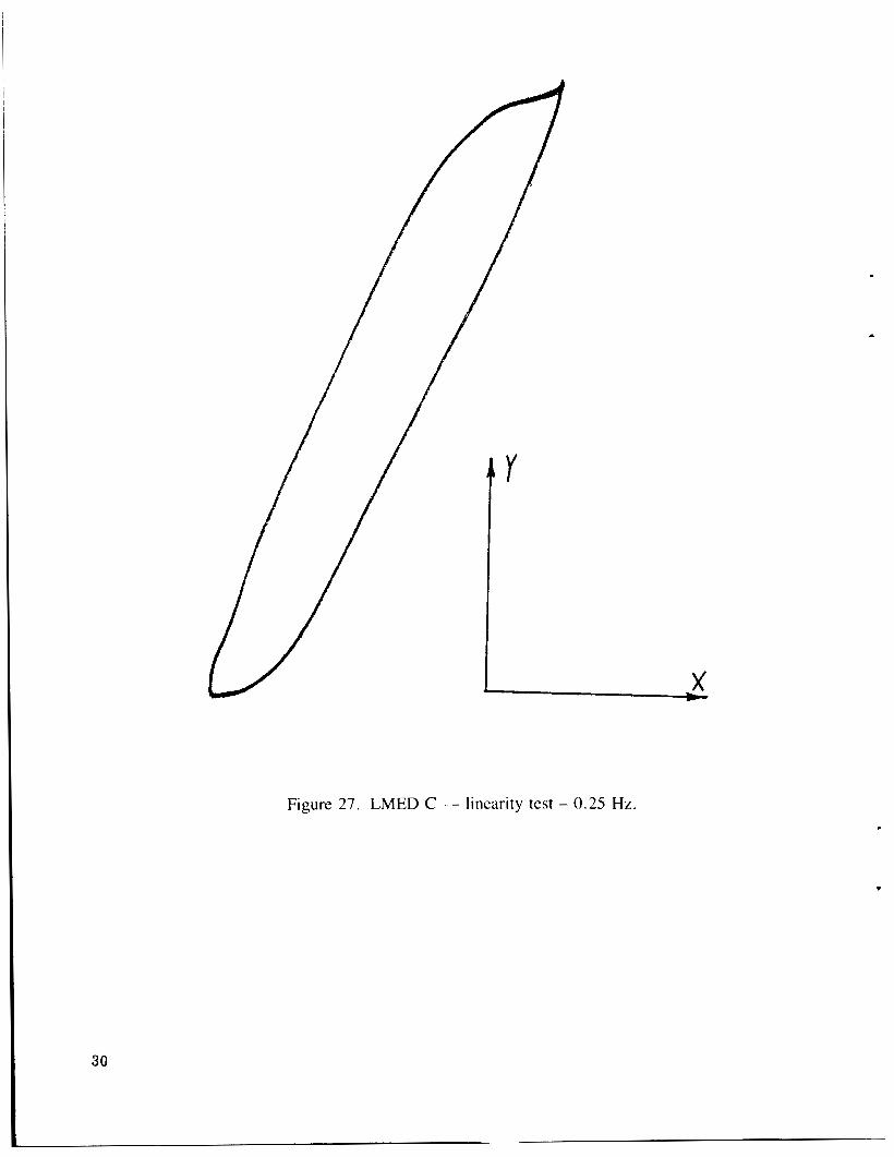
Figure 27. LMED C - linearity test - 0.25 Hz.
30
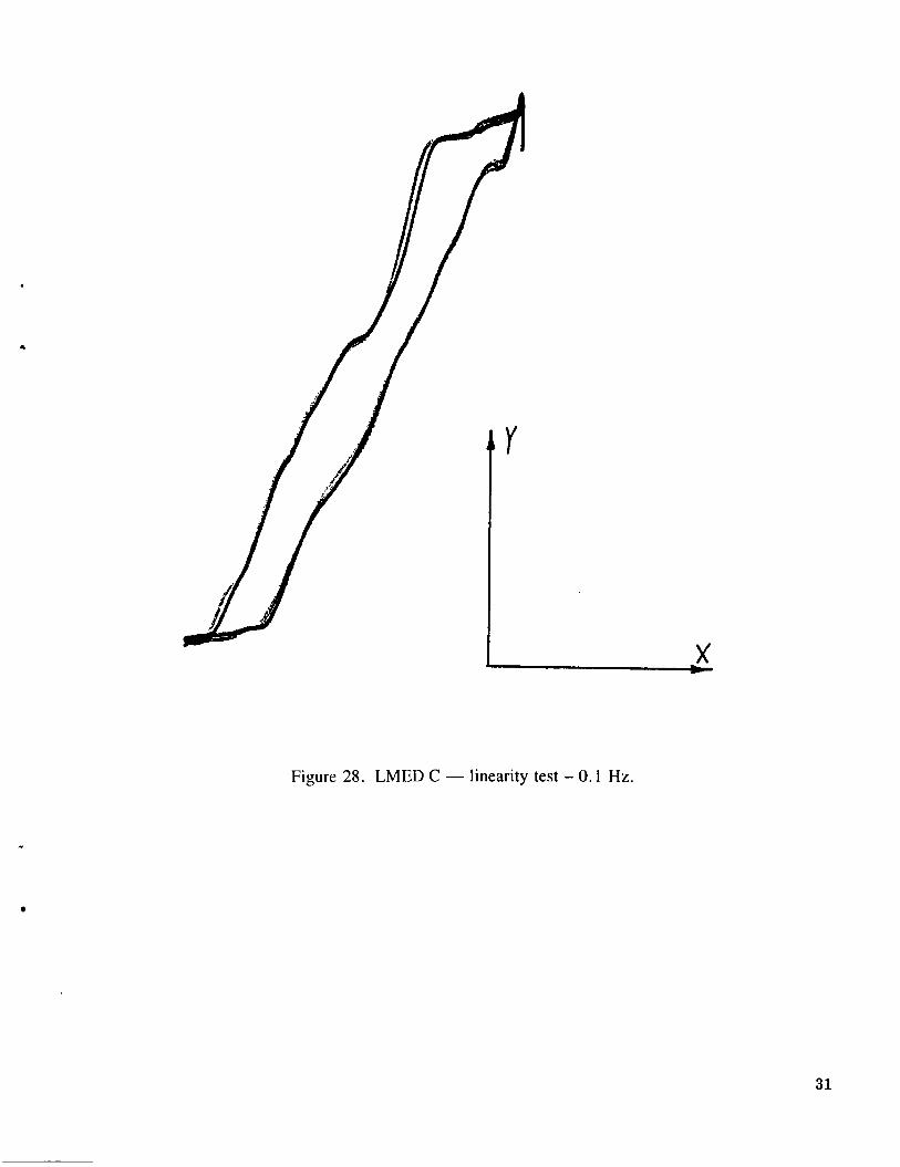
Figure 28. LMED C - linearity test - 0. I Hz.
31
~
I
LGttAC 4 I I -I
I I I
I
T--. ----I- - - LG HZ 5.0008
0. B i 50.000 m
TRANS #AI 50
t 50.008 m LC HZ
Figure 29. LMED D - frequency response.
32
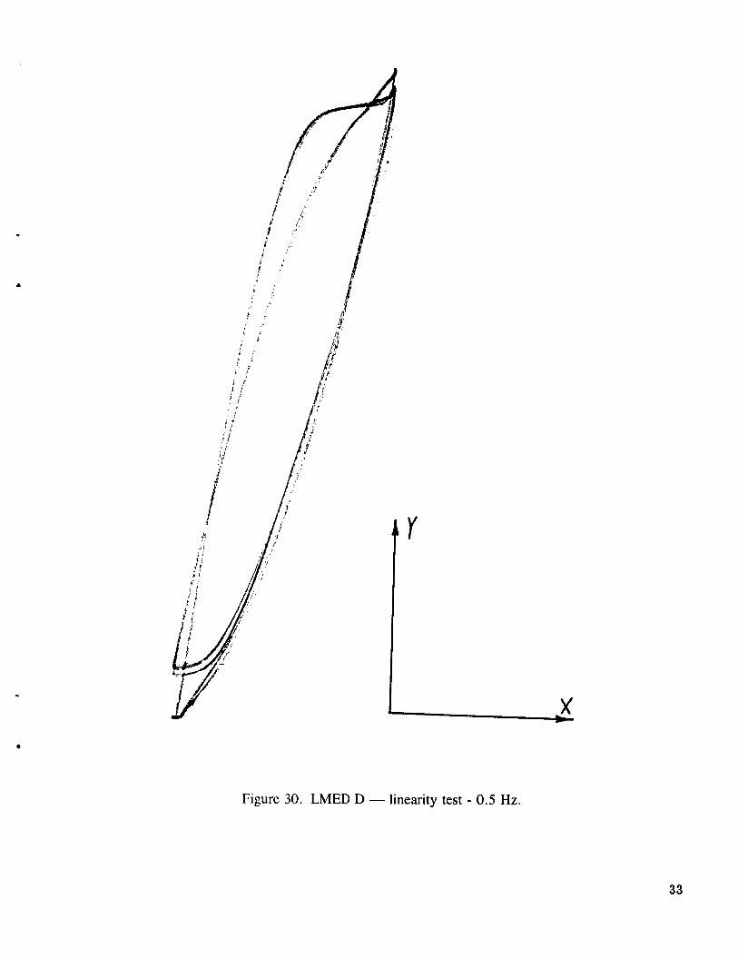
Figure 30. LMED D - linearity test - 0.5 Hz.
33
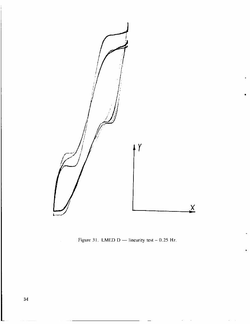
Figure 3 I . LMED D - linearity test - 0.25 Hz.
34
?
a
Figure 32. LMED D - linearity test - 0.1 Hz.
35
APPENDIX
MODIFICATION HISTORY
*
The following list contains in roughly chronological order the actions taken in the attempt to fix the LMEDs.
1 . NASA originally performed linearity tests on the C and D LMED units and ran frequency responses from motor input to LVDT sensed position. These tests indicated that problems existed with stiction and hysteresis in the actuator.
2. An LMED was delivered to Campbell Engineering for disassembly and analysis with the follow- ing findings.
a. LVDT alignment is difficult to maintain (new fastener fabricated).
b. Particulates were found in bearing area.
c. Shaft finish judged “acceptable” but could be improved.
d. The springs and shaft were found to be magnetic.
e . Bearings were ultrasonically cleaned.
t . Spring rates were measured.
3. The LMED was retested after cleaning and found to exhibit no noticeable change in perform- ance.
4. The bearings were oiled lightly and retested with no appreciable change in performance.
5 . The LMED was tested with the LVDT disconnected completely with no noticeable improvement in perlhrmance. (The proof mass exhibited same jump behavior with visual inspection.)
6. NASA I‘abricated a new non-magnetic shaft. Tests showed decreased (slight) hysteresis effects but n o noticeable decrease in stiction effects. NOTE: This shaft has visible surface im- perlec t ions.
7. Campbell quoted price on the modification of LMEDs to accept an air bearing in place of ball bearings. Further study of an air bearing modification was deemed necessary.
8. The Barden bearing company was consulted regarding problem. A bearing was suggested by Barden which may be ol’ better quality. The bearing was ordered from Dixie Bearing Co.
9. The Thompson Bearing Co. was consulted about the problem. Two different grades of bearings were ordered from Dixie Bearing. One of these bearings is an instrument grade bearing with a shaft of matching tolerances.
10. AI Smitek of Rexham Speedring was consulted concerning gas bearing construction. He indica- ted concern regarding modifying the current LMED to successfully utilize a gas bearing. He also indicated that the expense could be prohibitive.
1 I . A Thompson 48 12-SS bearing (steel housing version of current bearing) was obtained, installed, and tested using both original and new non-magnetic shaft without any appreciable improvement in performance.
12. Replacement bearings were obtained from Barden (LS-4) and Thompson (INST 4812-SS with <
matching shaft). These are to be tested.
13. A quote was received from Microsurface Ball Tech on the purchase of 200 1/16 in. diameter beryllium-copper balls to be used to replace the chrome-steel balls in one of the types of bearings (either the Super-4 or the INST 48 12-SS).
14. During trip to Speedring a conversation was held discussing the construction of an anti-magnetic shaft. The following conclusions were drawn regarding materials under consideration.
a . Series 300 stainless - antimagnetic but too soft to support load
b. Beryllium - antimagnetic but too soft to support load.
c. Titanium Carbide - sufficiently hard but slightly magnetic
d . Carbide - sufficiently hard but slightly magnetic.
e. Hard Anodized Aluminum - Completely antimagnetic and sufficiently hard to support load from balls. A hardness of Rockwell 60 is achieved to a depth of approximately 1/1000 in. below the surface.
A quote is to be received from Speedring for the manufacture of a hard anodized aluminum shaft. This will have a Rockwell hardness of approximately 60 (comparable to 440 case hardened stainless steel) and a smooth surface finish (approximately 2 to 3 micron). - Also discussed were possible materials to be used for replacement balls for the current bearings (Super 4, 4812). The materials as shown in the above list indicate that beryllium is too soft to be serviceable as a ball material. Industrial Techtonics Inc. is to be contacted regarding the possibi- lity of obtaining various ceramic or synthetic balls which would have the required hardness and anti-magnetic properties.
,
38
15. INST 48 12-SS bearings were installed and tested with matching shafts. This combination reduced stiction substantially but did not reduce hysteresis.
16. A hard anodized aluminum shaft made by Speedring was installed with the INST 4812-SS and substantially reduced both stiction and hysteresis.
The combination of the Thompson IST-4812 SS bearing and a Speedring produced hard anodized aluminum shaft with a 2 to 3 micron surface finish seems to produce the best performance combination yet achieved. The stiction and hysteresis effects are considerably reduced and allow the
P LMED to achieve reasonable operation at lower frequencies of actuation (0.1 Hz).
Y
39
k
APPROVAL
~ G. F. McDONOUGH
CHARACTERIZATION AND HARDWARE MODIF CATION OF LINEAR MOMENTUM EXCHANGE DEVICES
By George D. Edgemon, Sally Curtis, and Henry B . Waites
The information in this report has been reviewed for technical content. Review of any inform- ~
ation concerning Department of Defense or nuclear energy activities or programs has been made by the MSFC Security Classification Officer. This report, in its entirety, has been determined to be un- classified. a
*US. GOVERNMENT PRINTING OFFICE 1987-730-067/40126