Embed Size (px)
Citation preview
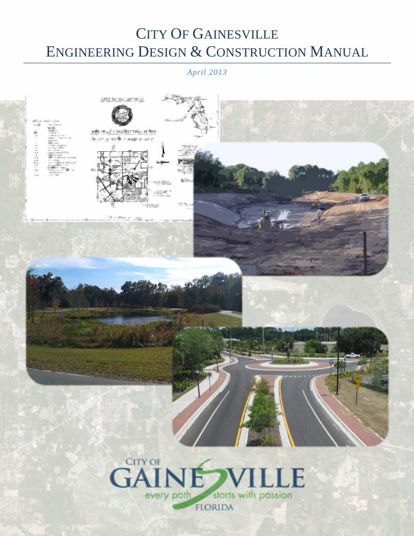
CITY OF GAINESVILLE ENGINEERING DESIGN & CONSTRUCTION MANUAL
April 2013
Legislative ID# 120970
RESOLUTION NO. XXXXXX PASSED April 18, 2013
A RESOLUTION OF THE CITY COMMISSION OF THE CITY OF GAINESVILLE, FLORIDA; INCORPORATING AND ADOPTING THE ENGINEERING DESIGN AND CONSTRUCTION MANUAL IN THE LAND DEVELOPMENT CODE; PROVIDING DIRECTIONS TO THE CODIFIER AND PROVIDING AN IMMEDIATE EFFECTIVE DATE.
Whereas, the Land Development Code addresses among other matters stormwater
management, flood control, roadway design, sidewalk design, bikeway design and traffic circulation for subdivision and site improvements within the City to protect the public health and safety and;
Whereas, the Land Development Code requires the City Commission to establish design standards and specifications for the development of subdivision and site plan improvements such as streets and roadways, stormwater management facilities and related appurtenances;
NOW, THEREFORE, BE IT RESOLVED BY THE CITY COMMISSION OF THE CITY OF GAINESVILLE, FLORIDA.
1. The City of Gainesville Engineering Design and Construction Manual, prepared by the Public Works Department, dated April 2013, and attached as Exhibit “A” and incorporated herein by reference, is adopted to define the engineering design standards and specifications for the development of subdivision and site improvements within the City of Gainesville.
2. This resolution shall become effective immediately upon adoption. PASSED AND ADOPTED this 18th day of April, 2013.
________________________ Craig Lowe Mayor
ATTEST: ___________________________ Kurt M. Lannon, Jr. Clerk of the Commission
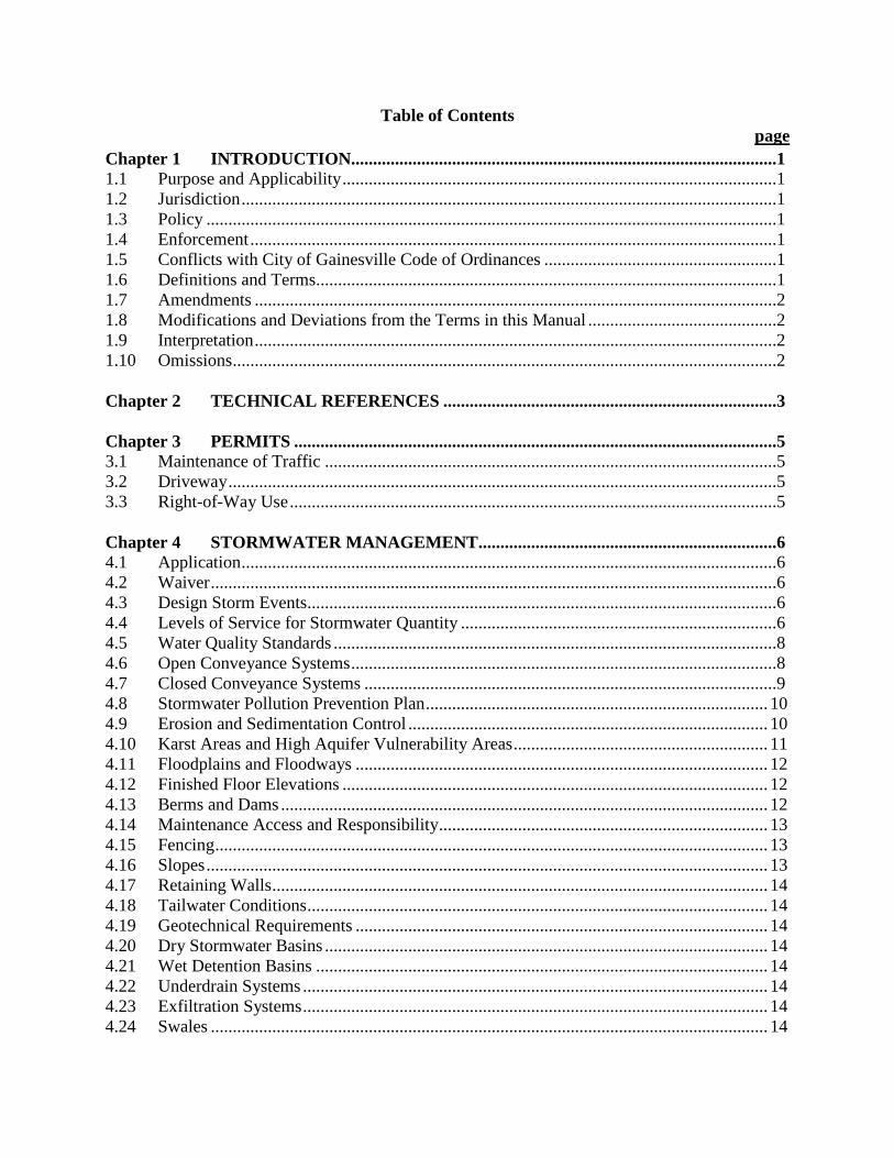
Table of Contents page
Chapter 1 INTRODUCTION.................................................................................................1 1.1 Purpose and Applicability ...................................................................................................1 1.2 Jurisdiction ..........................................................................................................................1 1.3 Policy ..................................................................................................................................1 1.4 Enforcement ........................................................................................................................1 1.5 Conflicts with City of Gainesville Code of Ordinances .....................................................1 1.6 Definitions and Terms.........................................................................................................1 1.7 Amendments .......................................................................................................................2 1.8 Modifications and Deviations from the Terms in this Manual ...........................................2 1.9 Interpretation .......................................................................................................................2 1.10 Omissions ............................................................................................................................2 Chapter 2 TECHNICAL REFERENCES ............................................................................3 Chapter 3 PERMITS ..............................................................................................................5 3.1 Maintenance of Traffic .......................................................................................................5 3.2 Driveway .............................................................................................................................5 3.3 Right-of-Way Use ...............................................................................................................5 Chapter 4 STORMWATER MANAGEMENT....................................................................6 4.1 Application ..........................................................................................................................6 4.2 Waiver .................................................................................................................................6 4.3 Design Storm Events...........................................................................................................6 4.4 Levels of Service for Stormwater Quantity ........................................................................6 4.5 Water Quality Standards .....................................................................................................8 4.6 Open Conveyance Systems .................................................................................................8 4.7 Closed Conveyance Systems ..............................................................................................9 4.8 Stormwater Pollution Prevention Plan .............................................................................. 10 4.9 Erosion and Sedimentation Control .................................................................................. 10 4.10 Karst Areas and High Aquifer Vulnerability Areas .......................................................... 11 4.11 Floodplains and Floodways .............................................................................................. 12 4.12 Finished Floor Elevations ................................................................................................. 12 4.13 Berms and Dams ............................................................................................................... 12 4.14 Maintenance Access and Responsibility ........................................................................... 13 4.15 Fencing .............................................................................................................................. 13 4.16 Slopes ................................................................................................................................ 13 4.17 Retaining Walls ................................................................................................................. 14 4.18 Tailwater Conditions ......................................................................................................... 14 4.19 Geotechnical Requirements .............................................................................................. 14 4.20 Dry Stormwater Basins ..................................................................................................... 14 4.21 Wet Detention Basins ....................................................................................................... 14 4.22 Underdrain Systems .......................................................................................................... 14 4.23 Exfiltration Systems .......................................................................................................... 14 4.24 Swales ............................................................................................................................... 14
4.25 Wetland Treatment Systems ............................................................................................. 15 Chapter 5 ROADWAY DESIGN ......................................................................................... 16 5.1 Geometrics ........................................................................................................................ 16 5.2 Intersections ...................................................................................................................... 16 5.3 Pavements ......................................................................................................................... 17 5.4 Utilities .............................................................................................................................. 18 5.5 Drainage ............................................................................................................................ 18 5.6 Sidewalks, Bike Lanes, Trails, Shared Paths and ADA Ramps ....................................... 18 5.7 Traffic Signals ................................................................................................................... 19 5.8 Traffic Signs...................................................................................................................... 21 5.9 Pavement Markings and Striping ...................................................................................... 23 5.10 Bridges and Other Structures ............................................................................................ 23 5.11 Transit Improvements ....................................................................................................... 23 5.12 Traffic Control .................................................................................................................. 23 5.13 Landscape and Streetscape ............................................................................................... 24 5.14 Lighting ............................................................................................................................. 24 5.15 Traffic Calming ................................................................................................................. 24 5.16 Design Variations and Exceptions .................................................................................... 24 Chapter 6 SITE DESIGN ..................................................................................................... 26 6.1 Driveways ......................................................................................................................... 26 6.3 Dumpster Pads .................................................................................................................. 26 6.3 Parking (off street) ............................................................................................................ 26 6.4 Public Sidewalks ............................................................................................................... 27 Chapter 7 TRAFFIC STUDY GUIDELINES .................................................................... 28 7.1 Study Thresholds .............................................................................................................. 28 7.2 Required Information ........................................................................................................ 28 7.3 Methodology Letter .......................................................................................................... 31 Chapter 8 SUBMITTAL REQUIREMENTS ..................................................................... 32 8.1 Site Plans ........................................................................................................................... 32 8.2 Subdivision Developments and Capital Improvement Plan (CIP) Roadway Projects ..... 34 8.3 As-built Plans .................................................................................................................... 37 Chapter 9 INSPECTION REQUIREMENTS .................................................................... 38 9.1 Permits .............................................................................................................................. 38 9.2 Inspections ........................................................................................................................ 38 9.3 Project Accessibility ......................................................................................................... 38 Chapter 10 CONSTRUCTION SPECIFICATIONS ........................................................... 39 10.1 Purpose .............................................................................................................................. 39 10.2 Preconstruction Meeting ................................................................................................... 39 10.3 Permits .............................................................................................................................. 39 10.4 Clearing and Grubbing ...................................................................................................... 39
10.5 Earthwork .......................................................................................................................... 41 10.6 Subgrade ........................................................................................................................... 43 10.7 Base Course ...................................................................................................................... 44 10.8 Drainage ............................................................................................................................ 46 10.9 Asphaltic Concrete ............................................................................................................ 51 10.10 Signing and Marking......................................................................................................... 51 10.11 Landscaping ...................................................................................................................... 51 10.12 Sampling and Testing Requirements ................................................................................ 51 10.13 Maintenance of Traffic ..................................................................................................... 54 10.14 Utility Accommodation Manual ....................................................................................... 55 APPENDIX A Definitions and Terms ............................................................................... A-1 APPENDIX B Standard Details ........................................................................................ B-1
Chapter 1 - Introduction
City of Gainesville Engineering Design & Construction Manual 1
Chapter 1 INTRODUCTION
1.1 Purpose and Applicability
The City of Gainesville Engineering Construction and Design Manual is adopted by resolution, pursuant to the authority granted by the City of Gainesville Comprehensive Plan. This manual further complements the requirements of the Land Development Code, Chapter 30, City of Gainesville Code of Ordinances. This manual seeks to implement City policy as outlined in the City’s Comprehensive Plan for the provision of transportation facilities that serve the needs of all users and promote a well-connected, integrated transportation system that reduces dependency on automobile use.
This manual establishes engineering design standards and specifications for the development of site plans, subdivisions, redevelopment projects, permits and capital projects within the City of Gainesville as part of the City’s responsibility to provide for the health, safety and welfare of the public.
1.2 Jurisdiction
This manual establishes engineering design standards and specifications for the development of site plans, subdivisions, redevelopment projects, permits and capital projects within the City of Gainesville. Where more stringent standards are imposed by federal, state and other local agencies, the more stringent standards having jurisdiction shall apply.
1.3 Policy When real property within the City of Gainesville is developed and/or redeveloped or any work is proposed within the City’s right-of-way (ROW) or easement, the infrastructure facilities contained within said property, serving said property or activities within the City ROW or easement shall comply with the requirements set forth in this manual and the Land Development Code.
1.4 Enforcement The Public Works Department, through their designated representatives, shall have the right to inspect the land and constructed facilities addressed by this manual and to issue “Notices to Comply” for violations or through a Site Plan Violation.
1.5 Conflicts with City of Gainesville Code of Ordinances When the standards and specifications included in the City of Gainesville Code of Ordinances and the manual conflict, the City of Gainesville Code of Ordinances shall apply.
1.6 Definitions and Terms The definitions of the terms used in this manual have the meanings respectively ascribed to them by common usage or specifically defined in those publications identified by
Chapter 1 - Introduction
City of Gainesville Engineering Design & Construction Manual 2
reference, except in those instances where the text clearly indicates a different meaning. The definitions or terms contained herein are not intended to alter definitions expressly specified in any other City of Gainesville ordinance, policy, regulation or code, but are provided for the purpose of making clear and distinct the intention of the language used in a specific section of this document. Following the Metropolitan Transportation Planning Organization (MTPO) Transportation Language Policy, objective language will be used avoiding biased terms. A list of commonly used terms and acronyms can be seen in Appendix I – Definitions and Terms.
1.7 Amendments The City of Gainesville shall amend the contents of this manual as may be required by Resolution of the City Commission.
1.8 Modifications and Deviations from the Terms in this Manual The appropriate reviewing board or designee may approve modifications from the requirements of the design manual when such modifications are not contrary to the public interest or where, owing to special conditions, a literal enforcement of the provisions of the design manual would result in unnecessary hardship. Modifications shall not be approved unless and until: A written application for modification is submitted along with the plat or
development plan demonstrating that special conditions and circumstances exist which are peculiar to the land, structures or required subdivision improvements involved and which are not applicable to other lands, structures or required subdivision improvements; and special conditions and circumstances do not result from the actions of the developer, owner, subdivider or recent predecessor in title;
The City Engineer makes a finding that the requirements of this section have been met;
The City Engineer makes a finding that the reasons set forth in the application justify the granting of the modification and the modification will make possible reasonable use of the land, buildings and other improvements; and
The City Engineer further finds that the granting of the modification would be in harmony with the general intent and purpose of the Land Development Code and the Comprehensive Plan, would not be injurious to surrounding properties, and would not otherwise be detrimental to the public health and welfare.
1.9 Interpretation
The City Engineer shall provide the final interpretation of the contents of this manual.
1.10 Omissions Logical, accountable, and generally accepted design standards and engineering judgment shall apply where not specifically addressed in this manual.
Chapter 2 - Technical References
City of Gainesville Engineering Design & Construction Manual 3
Chapter 2 TECHNICAL REFERENCES
Standards and guidelines which are referenced in most recent version of the following technical publications shall be considered part of this manual including subsequent updates or revisions to these publications. In the event of a conflicting standard imposed by the City, federal, state or other local agencies, the more stringent standard shall apply. AASHTO – A Policy on Geometric Design of Highways and Streets
ADA – Uniform Federal Accessibility Standards (UFAS); ADA Standards for Accessible Design (ADAAG); Public Rights of Way Accessibility Guidelines (PROWAG) Alachua County Low Impact Development Manual - DRAFT ASCE and WPCF – Design and Construction of Sanitary & Storm Sewers City of Gainesville – Standard Practice for Roadway Lighting
City of Gainesville – Streetscape Design and Technical Standards for City of Gainesville CRA Districts City of Gainesville – Regional Transit System Bus Stop Design Guidelines and Improvement Plan
DEP – Chapter 62-4, F.A.C., Permits
DEP – Chapter 62-25, F.A.C., Regulation of Stormwater Discharge
DEP – Chapter 62-302, F.A.C., Surface Water Quality Standards
DEP – Chapter 62-621, F.A.C., Generic Permits
DEP – Chapter 62-624, F.A.C., Municipal Separate Storm Sewer Systems
DEP – The Florida Stormwater, Erosion and Sedimentation Control Inspector’s Manual Department of Environmental Protection and Water Management Districts ERP Stormwater Quality Handbook – March 2010 DRAFT FDOT – Manual of Uniform Minimum Standards for Design, Construction and Maintenance for Streets and Highways (Commonly known as the “Florida Greenbook”)
FDOT – Standard Specifications for Road and Bridge Construction
FDOT – Procedures Manual for Flexible Pavement Design
Chapter 2 - Technical References
City of Gainesville Engineering Design & Construction Manual 4
FDOT – Roadway and Traffic Design Standards (FDOT Index) FDOT – Florida Roundabout Guide FDOT – Drainage Manual FDOT – Utility Accommodations Guide
FDOT – Plans Preparation Manual FDOT – Office of Construction Preparation and Documentation Manual
FDOT & FDEP – State of Florida Erosion and Sediment Control Designer and Reviewer Manual
FHWA – Manual on Uniform Traffic Control Devices (MUTCD) GRU – Design Standards and Construction Details for Potable Water, Reclaimed Water, and Wastewater (GRU Manual) ITE – Context Sensitive Solutions in Designing Major Urban Thoroughfares for Walkable Communities ITE – Trip Generation Manual MTPO – Urban Design Policy Manual, prepared for the Metropolitan Planning Organization for the Gainesville Urbanized Area by the North Central Florida Regional Planning Council SJRWMD – Technical Publication 85-5
SJRWMD – Applicants Handbook: Regulation of Stormwater Management Systems SJRWMD – Chapter 40C, F.A.C.: St. Johns River Water Management District SRWMD – Environmental Resource Permits Applicant’s Guide
SRWMD – Chapter 40B, F.A.C.: Suwannee River Water Management District Urban Land Institute and National Parking Association. (2000). The dimensions of parking, 4th Edition. Washington, D.C.: Urban Land Institute. USDA/NRCS – Technical Release 55 (TR-55)
Chapter 3 - Permits
City of Gainesville Engineering Design & Construction Manual 5
Chapter 3 PERMITS
3.1 Maintenance of Traffic
All permitting activities related to Maintenance of Traffic shall adhere to the City of Gainesville Code of Ordinances, Part II, Chapter 23 – Streets, Sidewalks and Other Public Places. Obtaining a Maintenance of Traffic Permit does not alleviate the requirements for other applicable permits, including but not limited to Driveway Permits and Right-of-Way Permits.
3.2 Driveway
All permitting activities related to driveways shall adhere to the City of Gainesville Code of Ordinances, Part II, Chapter 23 – Streets, Sidewalks and Other Public Places, specifically Article V Construction and Removal of Driveways. Obtaining a Driveway Permit does not alleviate the requirements for other applicable permits, including but not limited to Maintenance of Traffic Permits and Right-of-Way Permits.
3.3 Right-of-Way Use All permitting activities related to work in the public ROW shall adhere to the City of Gainesville Code of Ordinances, Part II, Chapter 23 – Streets, sidewalks and other public places. Obtaining a Right of Way Permit does not alleviate the requirements for other applicable permits, including but not limited to Driveway Permits and Maintenance of Traffic Permits. The applicant must move or remove facilities located in the public ROW, regardless of permit status, in accordance with the approved schedule provided to the City. Work in the public ROW which qualifies for a permit exemption under Section 23-40 and is emergent in nature, shall provide the City with the information required in a permit application once the situation has been stabilized.
Chapter 4 - Stormwater Management
City of Gainesville Engineering Design & Construction Manual 6
Chapter 4 STORMWATER MANAGEMENT
The objective of this section of the manual is to provide the design standards necessary for the conservation and improvement of the quality of the surface waters and the control of stormwater runoff volume and rate and floodplain elevations in the City of Gainesville. 4.1 Application
The following activities will be required to meet the stormwater management requirements of this manual: New development with 1,000 SF to 1,999 SF net new impervious area or
redevelopment with 4,000 SF or more redeveloped area are required to meet stormwater quality requirements.
New development with 2,000 SF or more net new impervious area is required to meet stormwater quantity and quality requirements.
4.2 Waiver
A waiver from particular stormwater management requirements may be granted by the City Engineer provided the proposed modifications do not result in significant detrimental impacts to the stormwater quantity or quality, the environment, or public health, safety or welfare and the project meets all other applicable state and federal requirements.
Waivers will not be granted where current site conditions are in violation of any water quality standards or contribute to an area with significant flooding problems.
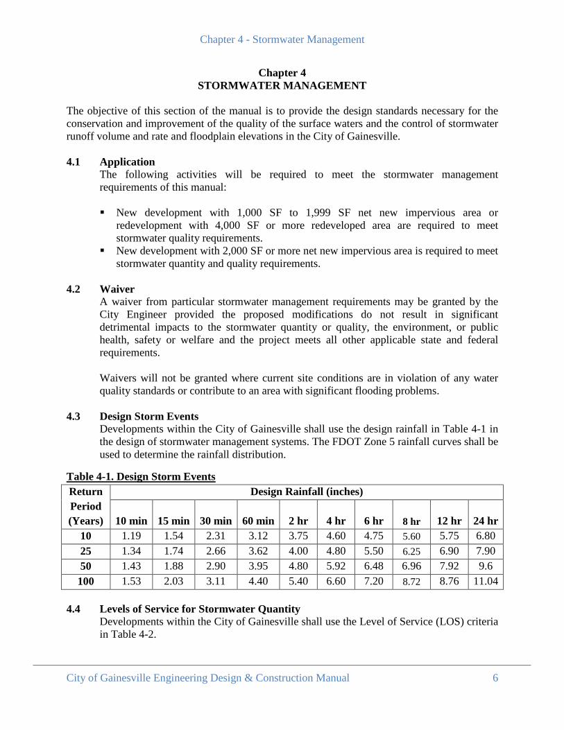
4.3 Design Storm Events Developments within the City of Gainesville shall use the design rainfall in Table 4-1 in the design of stormwater management systems. The FDOT Zone 5 rainfall curves shall be used to determine the rainfall distribution.
Table 4-1. Design Storm Events Return Period (Years)
Design Rainfall (inches)
10 min 15 min 30 min 60 min 2 hr 4 hr 6 hr 8 hr 12 hr 24 hr 10 1.19 1.54 2.31 3.12 3.75 4.60 4.75 5.60 5.75 6.80 25 1.34 1.74 2.66 3.62 4.00 4.80 5.50 6.25 6.90 7.90 50 1.43 1.88 2.90 3.95 4.80 5.92 6.48 6.96 7.92 9.6 100 1.53 2.03 3.11 4.40 5.40 6.60 7.20 8.72 8.76 11.04
4.4 Levels of Service for Stormwater Quantity
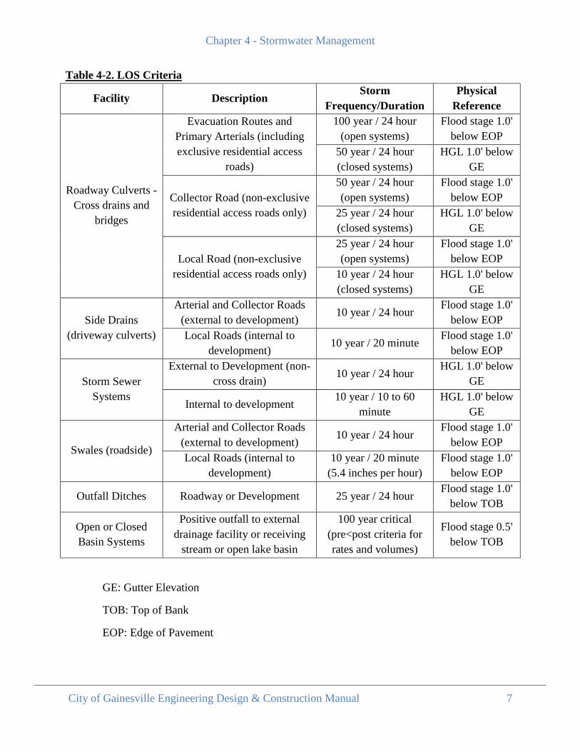
Developments within the City of Gainesville shall use the Level of Service (LOS) criteria in Table 4-2.
Chapter 4 - Stormwater Management
City of Gainesville Engineering Design & Construction Manual 7
Table 4-2. LOS Criteria
Facility Description Storm
Frequency/Duration Physical
Reference
Roadway Culverts - Cross drains and
bridges
Evacuation Routes and Primary Arterials (including exclusive residential access
roads)
100 year / 24 hour (open systems)
Flood stage 1.0' below EOP
50 year / 24 hour (closed systems)
HGL 1.0' below GE
Collector Road (non-exclusive residential access roads only)
50 year / 24 hour (open systems)
Flood stage 1.0' below EOP
25 year / 24 hour (closed systems)
HGL 1.0' below GE
Local Road (non-exclusive residential access roads only)
25 year / 24 hour (open systems)
Flood stage 1.0' below EOP
10 year / 24 hour (closed systems)
HGL 1.0' below GE
Side Drains (driveway culverts)
Arterial and Collector Roads (external to development)
10 year / 24 hour Flood stage 1.0'
below EOP Local Roads (internal to
development) 10 year / 20 minute
Flood stage 1.0' below EOP
Storm Sewer Systems
External to Development (non-cross drain)
10 year / 24 hour HGL 1.0' below
GE
Internal to development 10 year / 10 to 60
minute HGL 1.0' below
GE
Swales (roadside)
Arterial and Collector Roads (external to development)
10 year / 24 hour Flood stage 1.0'
below EOP Local Roads (internal to
development) 10 year / 20 minute
(5.4 inches per hour) Flood stage 1.0'
below EOP
Outfall Ditches Roadway or Development 25 year / 24 hour Flood stage 1.0'
below TOB
Open or Closed Basin Systems
Positive outfall to external drainage facility or receiving
stream or open lake basin
100 year critical (pre<post criteria for rates and volumes)
Flood stage 0.5' below TOB
GE: Gutter Elevation
TOB: Top of Bank
EOP: Edge of Pavement
Chapter 4 - Stormwater Management
City of Gainesville Engineering Design & Construction Manual 8
Within the Hogtown Creek Basin, systems must be designed to retain any increase in volume of runoff over the predevelopment volume for a 72-hour period under all 100 year storm events.
All stormwater systems shall be evaluated for the 100 year critical storm events to establish the minimum finished floor elevations of surrounding structures (to 1’ above the 100 year elevation).
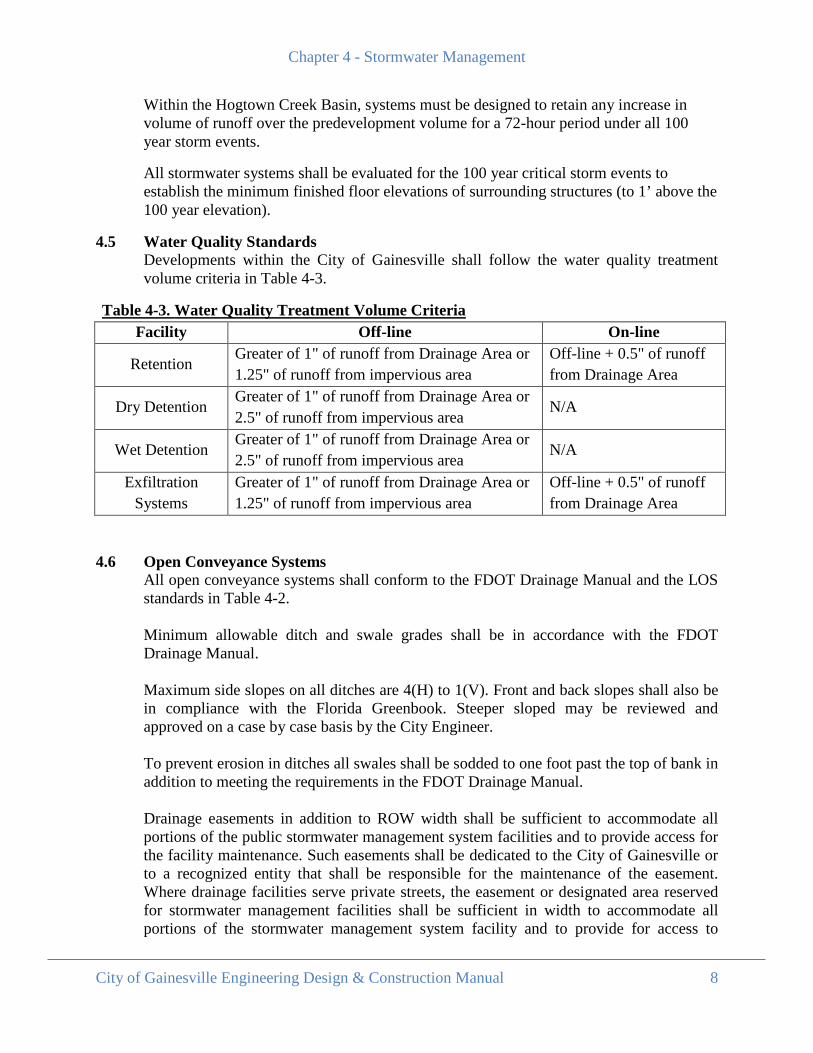
4.5 Water Quality Standards Developments within the City of Gainesville shall follow the water quality treatment volume criteria in Table 4-3.
Table 4-3. Water Quality Treatment Volume Criteria Facility Off-line On-line
Retention Greater of 1" of runoff from Drainage Area or 1.25" of runoff from impervious area
Off-line + 0.5" of runoff from Drainage Area
Dry Detention Greater of 1" of runoff from Drainage Area or 2.5" of runoff from impervious area
N/A
Wet Detention Greater of 1" of runoff from Drainage Area or 2.5" of runoff from impervious area
N/A
Exfiltration Systems
Greater of 1" of runoff from Drainage Area or 1.25" of runoff from impervious area
Off-line + 0.5" of runoff from Drainage Area
4.6 Open Conveyance Systems
All open conveyance systems shall conform to the FDOT Drainage Manual and the LOS standards in Table 4-2. Minimum allowable ditch and swale grades shall be in accordance with the FDOT Drainage Manual. Maximum side slopes on all ditches are 4(H) to 1(V). Front and back slopes shall also be in compliance with the Florida Greenbook. Steeper sloped may be reviewed and approved on a case by case basis by the City Engineer. To prevent erosion in ditches all swales shall be sodded to one foot past the top of bank in addition to meeting the requirements in the FDOT Drainage Manual. Drainage easements in addition to ROW width shall be sufficient to accommodate all portions of the public stormwater management system facilities and to provide access for the facility maintenance. Such easements shall be dedicated to the City of Gainesville or to a recognized entity that shall be responsible for the maintenance of the easement. Where drainage facilities serve private streets, the easement or designated area reserved for stormwater management facilities shall be sufficient in width to accommodate all portions of the stormwater management system facility and to provide for access to
Chapter 4 - Stormwater Management
City of Gainesville Engineering Design & Construction Manual 9
maintain the facility. Such easements shall be dedicated to a responsible private maintenance entity.
4.7 Closed Conveyance Systems All closed conveyance systems shall conform to the FDOT Drainage Manual and the LOS standards in Table 4-2. Wet piping systems are discouraged and should not be used when feasible.
4.7.1 Inlets All inlets with grates shall be per FDOT standards. Curb inlets are not allowed at pedestrian crossings or within curb returns at
intersections. All inlets and manholes with removable tops that are to be maintained by the Public
Works Department shall have 2 foot sumps. A new structure shall be provided at any change in alignment and elevation of pipe. Elliptical pipes are permitted. Ram-neck connections are not permitted. All junction structures with sumps shall have the tops of the intersecting pipes at the
same elevation for all pipes entering or exiting the structure. The two foot sump requirement shall be measured from the lowest invert of the pipe in the structure. No sumps are required on wet piping systems.
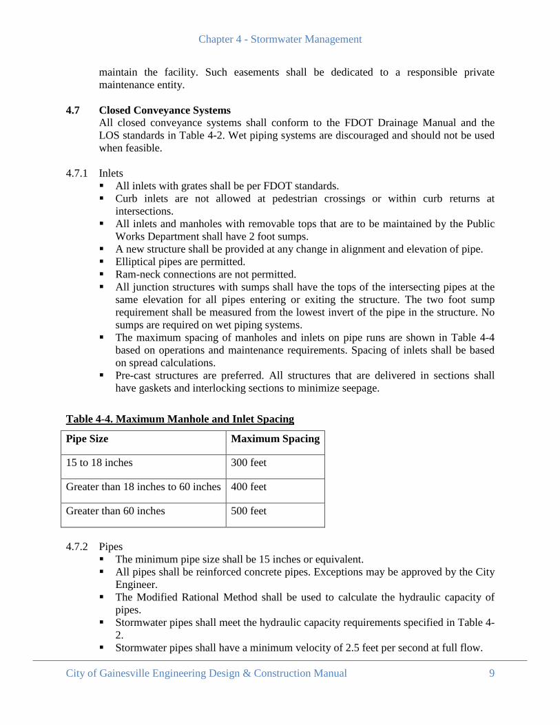
The maximum spacing of manholes and inlets on pipe runs are shown in Table 4-4 based on operations and maintenance requirements. Spacing of inlets shall be based on spread calculations.
Pre-cast structures are preferred. All structures that are delivered in sections shall have gaskets and interlocking sections to minimize seepage.
Table 4-4. Maximum Manhole and Inlet Spacing
Pipe Size Maximum Spacing
15 to 18 inches 300 feet
Greater than 18 inches to 60 inches 400 feet
Greater than 60 inches 500 feet
4.7.2 Pipes
The minimum pipe size shall be 15 inches or equivalent. All pipes shall be reinforced concrete pipes. Exceptions may be approved by the City
Engineer. The Modified Rational Method shall be used to calculate the hydraulic capacity of
pipes. Stormwater pipes shall meet the hydraulic capacity requirements specified in Table 4-
2. Stormwater pipes shall have a minimum velocity of 2.5 feet per second at full flow.
Chapter 4 - Stormwater Management
City of Gainesville Engineering Design & Construction Manual 10
All outfall structures shall have energy dissipating blocks or equivalent energy dissipating mechanisms to prevent these areas from eroding.
All pipes shall be joined with approved gaskets to minimize seepage.
4.8 Stormwater Pollution Prevention Plan All Stormwater Pollution Prevention Plans shall be developed in accordance with the FDEP requirements of Rule 62-621.300 Generic Permits.
4.9 Erosion and Sedimentation Control
Development shall provide temporary and/or permanent erosion and sedimentation control best management practices prior to any clearing or alteration of land. Areas of application include but are not limited to perimeter, inlet, outlet, slope, and ditch protection measures. The protective measures shall remain installed and be regularly maintained for the duration of the project or until the site is properly stabilized with permanent protective measures.
4.9.1 Stabilization of Denuded Areas and Soil Stockpiles
Permanent or temporary soil stabilization shall be applied to denuded areas within 15 days after final grade is reached on any portion of the site. Soil stabilization shall be applied within 15 days to denuded areas which may not be at final grade but will remain dormant (undisturbed) for longer than 30 days. A phasing plan will be required for activities longer than 30 days. A phasing plan will also be required for denuded areas over 1 acre regardless of the dormant time period. Soil stockpiles that will be dormant for more than 7 days shall be surrounded with silt fencing to prevent off site sediment tracking.
4.9.2 Establishment Of Permanent Vegetation
Permanent vegetative cover shall be established on denuded areas not otherwise permanently stabilized. Permanent vegetation shall not be considered established until a ground cover is achieved which is mature enough to control soil erosion.
4.9.3 Timing and Stabilization of Sediment Trapping Measures Sediment basins and traps, perimeter dikes, sediment barriers and other measures intended to trap sediment on-site shall be constructed as a first step in grading and be made functional before upslope land disturbances takes place. Earthen structures such as dams, dikes and diversions shall be seeded and mulched within 15 days of installation.
4.9.4 Cut and Fill Slopes Cut and fill slopes shall be designed and constructed in a manner which will minimize erosion. Consideration must be given to the length and steepness of the slope, the soil type, upslope drainage area, groundwater conditions and other applicable factors. Slopes which are found to be eroding excessively within one year of construction shall be provided with additional slope stabilizing measures until the problem is corrected.
4.9.5 Storm Pipe Inlet Protection
Chapter 4 - Stormwater Management
City of Gainesville Engineering Design & Construction Manual 11
All storm pipe inlets which are made operable during construction shall be protected so that sediment-laden water will not enter the conveyance system without first being filtered or otherwise treated to remove sediment.
4.9.6 Construction Access Routes Wherever construction vehicle access routes intersect paved public roads, provisions shall be made to minimize the transport of sediment (mud), concrete, and other construction materials by runoff or vehicle tracking onto the paved surface. Where sediment is transported onto a public road surface, the road shall be cleaned thoroughly at the end of each work day. Sediment shall be removed from roads by shoveling or sweeping and be transported to a controlled sediment disposal area. Street washing shall be allowed only after sediment is removed in this manner.
4.9.7 Removal of Temporary Measures
All temporary erosion and sediment control measures shall be removed of within 30 days after final site stabilization is achieved or after the temporary measures are no longer needed, unless otherwise authorized. Trapped sediment and other disturbed soil areas resulting from the removal of temporary measures shall be permanently stabilized to prevent further erosion and sedimentation.
4.9.8 Maintenance
All temporary and permanent erosion and sediment control practices shall be maintained and repaired as needed to assure continued performance of their intended function.
4.10 Karst Areas and High Aquifer Vulnerability Areas
All stormwater management facilities and systems shall be designed and constructed to ensure that adequate treatment of stormwater runoff is provided prior to this runoff being discharged to the aquifer. The stormwater management facility and system shall be designed to prevent the formation of sinkholes. A map of the most recent Aquifer Vulnerability Zones can be obtained from the water management district. In an effort to prevent untreated stormwater runoff discharging into the aquifer, stormwater management facilities and systems located in sensitive karst areas and areas of High Aquifer Vulnerability as delineated by the appropriate water management district shall adhere to the minimum following design standards:
A minimum of 3 feet of unconsolidated soil material is required between the surface
of the limestone bedrock and the bottom and sides of the stormwater management facility. The City Engineer shall approve the type of excavation and backfill material that will be used to meet these criteria.
Stormwater management facilities shall be designed to be as shallow as possible with horizontal bottoms. Deeper areas shall not be allowed in the bottom of the facility unless approved by the City Engineer.
To prevent the formation of sinkholes, the maximum facility depth shall be ten (10) feet.
Chapter 4 - Stormwater Management
City of Gainesville Engineering Design & Construction Manual 12
The stormwater management facility side slopes, bottoms and areas adjacent to the facility that were disturbed or altered during construction shall be fully vegetated and stabilized.
All fill material used onsite shall be free of phosphatic Hawthorn Group sediments or other phosphorous rich materials that may leach phosphorus causing surface water quality degradation and lake eutrophication.
Any excavation that would lead to exposure of Hawthorn Group sediments or other phosphorus rich materials that could leach and adversely impact groundwater or surface water shall be mitigated by covering, backfilling or using other techniques to prevent phosphorus leaching.
Utility lines shall not be installed beneath stormwater basins in karst sensitive areas unless approved by the City Engineer and GRU. Any lines for temporary irrigation of vegetation in and around stormwater management systems shall be installed to minimize excavation in karst sensitive areas.
4.11 Floodplains and Floodways
In general, a loss of onsite floodplain storage will result in an increase in the offsite floodplain. As such, developments that encroach into a 100 year floodplain as designated by FEMA and the City of Gainesville, or any other determination by a jurisdictional authority shall demonstrate that the loss of onsite storage will not cause adverse offsite impacts to the floodplain. Additionally, the base flood elevation and the finished floor elevations for existing and proposed structures must be identified for projects located within the floodplain. Any development within a 100 year floodplain shall not increase the base flood elevation. No permanent structures or fills shall be allowed in the 10-year flood channel except structures and fills designed for flood prevention and control, streets, bridges and sanitary sewer lift stations and utility lines. Structures that are permitted in the 10-year flood channel shall demonstrate that no adverse impacts result from placing the structure within the 10-year flood channel (i.e., there is no increase in the elevation and limits of the 10-year flood channel or floodplain and no changes to the upstream or downstream 10-year flood channel or floodplain).
4.12 Finished Floor Elevations
Finished-floor elevations of structures adjacent to or that could potentially be impacted by the stormwater management facility shall be elevated at least one foot above the design high water elevation or base flood elevation (whichever is higher) so that the structure is adequately protected from a basin overtopping event. All stormwater management systems shall be evaluated for the 100 year critical storm event to establish the minimum finished floor elevation.
4.13 Berms and Dams All stormwater basins that are created by damming or berming shall be designed with a minimum of 12 inches freeboard. A slope stability analysis shall be performed by a registered Professional Engineer on embankments which may pose a threat to public safety. A stability analysis shall be performed on embankments greater than 6 feet tall or embankments that are directly
Chapter 4 - Stormwater Management
City of Gainesville Engineering Design & Construction Manual 13
upstream from a structure, public facility or other floodwater sensitive facilities. Documentation of the slope stability factor shall be provided with the stability analysis. Seepage through the berm or dam and erosion should be of major concern when specifying fill soil type, placement methods, and compaction. Field density tests shall be required by the City Engineer and these tests shall be made in accordance with FDOT standards and reported in writing to the City Engineer.
4.14 Maintenance Access and Responsibility Reasonable maintenance access to all stormwater management facilities shall be provided. As a guideline, the maintenance path shall have a minimum cleared width of 8 feet, a maximum slope of 8H:1V, and be stabilized with grass. Stormwater management facilities within subdivisions or that are maintained by the City shall provide a minimum cleared maintenance path width of 15 feet. The entity responsible for all maintenance on the stormwater structures and facilities shall clearly be identified through a letter to the Public Works Department Director, the subdivision plat or the approved site plan.
4.15 Fencing
Stormwater management facilities shall be fenced, if necessary, in accordance with the appropriate water management district criteria. If the stormwater management facility does not meet the permitting threshold of the appropriate water management district, the facility shall be fenced as follows. Perimeter fencing shall be required for stormwater basins with one or more of the following characteristics:
Dry basins with a depth greater than 6 feet, as measured from the basin bottom to the
control elevation, and with slopes steeper than 4H:1V. Full retention basin without an outfall if the design high-water elevation for the
design storm is greater than 4 feet deep and the side slopes are steeper than 6H:1V, except where the side slopes are shallower than 6H:1V to a depth that is at least 4 feet lower than the design high-water elevation.
Wet detention basins with a normal pool depth 8 feet or greater, except where the side slopes are shallower than 6H:1V to a depth that is at least 4 feet lower than the permanent-pool elevation.
Perimeter fencing, where provided, shall be a minimum of 4 feet in height and have a gate that allows easy access for maintenance equipment. Fencing styles are subject to approval by the water management district and City Engineer.
4.16 Slopes
All sloped areas within stormwater basin and swales/ditches shall be sodded or planted. Slopes steeper than 4:1 shall be pinned. Basins are encouraged to be constructed with no parallel sides.
Chapter 4 - Stormwater Management
City of Gainesville Engineering Design & Construction Manual 14
4.17 Retaining Walls The following requirements apply to retaining walls or near-vertical soil retaining structures used to form stormwater management facilities or portions of stormwater management facilities:
Fencing or protective barriers may be required as determined by the City Engineer. The wall shall be designed with materials that prevent sediment seepage into the
stormwater management facility and that do not require regular maintenance to properly function. Railroad ties, wooded planks, and other similar materials should not be used within stormwater management facilities.
Sufficient access for maintenance equipment is required in accordance with the requirements of this chapter.
4.18 Tailwater Conditions
Tailwater impacts to outfall/outlet structures shall be evaluated as part of the design process. Guidance on accounting for tailwater impacts can be found in the FDOT Drainage manual.
4.19 Geotechnical Requirements All basins shall require geotechnical borings. Documentation of the geotechnical parameters should be submitted to the City by a licensed geotechnical engineer. Methods of testing should be done in accordance with the SJRWMD Applicant’s Handbook: Regulation of Stormwater Management Systems Chapter 40C-42 F.A.C. The number of borings required shall be in accordance with Section 26.4 of the SJRWMD Applicant’s Handbook: Regulation of Stormwater Management Systems Chapter 40C-42 F.A.C.
4.20 Dry Stormwater Basins All dry (retention and detention) stormwater basins shall be designed in accordance with the LOS criteria in Table 4-2 and Sections 10.0 and 11.0 of the SJRWMD Applicant’s Handbook: Regulation of Stormwater Management Systems Chapter 40C-42 F.A.C.
4.21 Wet Detention Basins All wet detention basins shall be designed in accordance with the LOS criteria in Table 4-2 and Section 14.0 of the SJRWMD Applicant’s Handbook: Regulation of Stormwater Management Systems Chapter 40C-42 F.A.C. Wet detention basins shall be sodded to the normal high water level in the basin at the time of construction.
4.22 Underdrain Systems
All underdrain systems shall be designed in accordance with the SJRWMD Applicant’s Handbook: Regulation of Stormwater Management Systems Chapter 40C-42 F.A.C.
4.23 Exfiltration Systems All exfiltration systems shall be designed in accordance with the SJRWMD Applicant’s Handbook: Regulation of Stormwater Management Systems Chapter 40C-42 F.A.C.
4.24 Swales
Chapter 4 - Stormwater Management
City of Gainesville Engineering Design & Construction Manual 15
All swale systems shall be designed in accordance with the LOS criteria in Table 4-2 and the SJRWMD Applicant’s Handbook: Regulation of Stormwater Management Systems Chapter 40C-42 F.A.C.
4.25 Wetland Treatment Systems All wetland treatment systems shall be designed in accordance with the LOS criteria in Table 4-2 and the SJRWMD Applicant’s Handbook: Regulation of Stormwater Management Systems Chapter 40C-42 F.A.C.
Chapter 5 - Roadway Design
City of Gainesville Engineering Design & Construction Manual 16
Chapter 5 ROADWAY DESIGN
5.1 Geometrics
The geometric design of a roadway shall consider the needs of drivers, bicyclists, and pedestrians implementing ‘complete streets’ elements. Opportunities shall be maximized to promote interconnectivity of modes. Where feasible, particularly in conjunction with land development or redevelopment, the design shall incorporate pedestrian scale blocks to create a gridded transportation network and facilitate the movement of all users. Geometrics shall be designed in accordance with the Manual of Uniform Minimum Standards for Design, Construction and Maintenance for Streets and Highways “Florida Greenbook,” the guidance of the Institute of Transportation Engineers “Designing Walkable Urban Thoroughfares: A Context Sensitive Approach,” and other provisions contained herein. In the event that it is necessary to deviate from these standards, a design variance or exception is required.
5.2 Intersections
Intersection design shall provide: Safe and convenient operation for all road users, including cyclists and pedestrians Proper accessibility for pedestrians with special needs Adequate maneuvering for design vehicles Resolution of conflicts between competing movements Reasonable delineation of vehicle paths Adequate visibility of conflicting traffic Storage for normal queue of vehicles Appropriate access management application Necessary regulatory, warning and informational messages for all road users Uniformity of treatment with similar locations The Florida Greenbook shall provide the minimum standards for different types of intersections. Additional provisions for the design of intersections may apply depending upon the context.
5.2.1 Roundabouts Roundabouts shall be designed in accordance with the Florida Roundabout Guide. A roundabout shall consist of a circulating roadway around a raised central island. Other components shall include: Landscaped area in central island Non-mountable curb (i.e. Type D) around perimeter of landscaped area Mountable curb & gutter (i.e. Type E) around perimeter of central island Raised splitter islands Streetscape elements including clay bricks Landscaping meeting scale of roundabout
Chapter 5 - Roadway Design
City of Gainesville Engineering Design & Construction Manual 17
Safe accommodations for bicyclists and pedestrians. This can be accomplished with bike access ramps that can provide an alternative for bicyclists to get off the bike lanes and onto the sidewalk or multi-use paths before going through the roundabout. An example of this can be seen in Appendix B.
See Appendix B for a typical roundabout detail. This detail should be used for guidance on the types of curb permitted in the roundabout, types of pavement and material allowed in the roundabout and recommended pedestrian and bicycle facilities through the roundabout. Dimensions and radii of the roundabout shall be in accordance with the Florida Roundabout Guide.
5.3 Pavements 5.3.1 Flexible Pavement
Flexible pavements are to be evaluated and designed in accordance with the FDOT Flexible Pavement Design Manual and FDOT Design Standards index 514. Additional provisions for the design of flexible pavements are as follows:
A typical flexible pavement design consists of stabilized subgrade, base, and asphalt
pavement. Roadway pavement materials shall be FDOT approved and from FDOT approved sources.
Asphalt Concrete shall be Superpave only. Graded aggregate or crushed concrete base materials are strongly encouraged.
Limerock bases with underdrain systems will also be considered for approval. Subgrade materials shall be Type B Stabilization (LBR 30 or 40). Friction courses should be used to improve skid resistance on roads having an ADT
of 3,200 or more and a Design Speed greater than 35 MPH. Friction courses may be required in areas of steep vertical slopes.
The minimum flexible pavement design should include: 2” SP 9.5 Asphalt; 6” base and 12” stabilized subgrade.
Asphalt trails and multi-use paths shall be constructed to the following specifications: 1.5" of SP 9.5, 6" Limerock Base (LBR100) and 12" Stabilized Subgrade.
5.3.2 Rigid Pavement
The use of concrete (rigid) pavement may be used in lieu of flexible pavement if its structural capacity meets or exceeds the values for the minimum flexible pavement sections. Like flexible pavement, concrete pavement will require an increase of its structural capacity if warranted by the type and amount of vehicular traffic loading. The design of rigid pavement shall conform to the requirements of AASHTO Interim Guide for Design of Pavement Structures 1972, Chapter III (Revised 1981).
5.3.3 Alternative Design
Alternative pavement designs such as brick shall conform to the same structural standards as the minimum flexible pavement design. A 6” concrete base constructed beneath the brick ensures the structural standards are met.
5.3.4 Additional Criteria
Chapter 5 - Roadway Design
City of Gainesville Engineering Design & Construction Manual 18
More stringent structural standards shall apply when warranted by the type and amount of vehicular loading.
5.4 Utilities
Utilities shall be designed in accordance with the FDOT Utility Accommodation Manual (with City of Gainesville Public Works Department substituted for FDOT and as modified by the Public Works Department in conjunction with the utilities), GRU specifications and the Florida Greenbook. Any utility work within the ROW will require the necessary permits from the Public Works Department (Right-of-Way use and/or Maintenance of Traffic permits). Utility work will be coordinated with any ongoing or future roadway and drainage projects to the extent possible. Some exceptions will apply for emergency work. Approved Utility Work Schedules (UWS) will be required for all utility work proposed in conjunction with any roadway project. Utility owners will be responsible for maintaining as-builts on all utility work in the public ROW. Road, trail and sidewalk surfaces newer than 5 years old shall not be open cut. Any allowable open cut shall be repaired with in kind materials or better. The repair method and size of the patch will be at the discretion of the City Engineer. Open cuts will be allowed for emergency situations. Exemptions to this may be approved by the City Engineer.
5.5 Drainage
All roadway projects must adhere to the design criteria established in Chapter 4 – Stormwater Management. Inverted crowned roads are not permitted except in special cases, such as alleyways, as approved by the City Engineer.
5.6 Sidewalks, Bicycle Lanes, Trails, Shared Paths and ADA Ramps 5.6.1 Sidewalks, Bicycle Lanes, Trails and Shared Use Paths
Sidewalks, bicycle lanes, trails and shared use paths shall be designed in accordance with the Florida Greenbook, FDOT Indices and CRA streetscape standards when applicable. All markings and signage shall be in accordance with the MUTCD.
In areas of high pedestrian traffic the sidewalk width should be maximized to provide adequate accommodation to all users. The minimum sidewalk width to avoid point obstacles is 42 inches. The sidewalk should have a 5 foot long taper down to 42 inches, be at 42 inches for 5 feet and then taper back to sidewalk width in 5 feet.
5.6.2 ADA Ramps ADA ramps shall be designed in accordance with the Florida Greenbook, FDOT Indices, and CRA streetscape standards (when applicable) except for the following provisions: Detectable warning color to provide light/dark contrast of 70% of sidewalk.
Chapter 5 - Roadway Design
City of Gainesville Engineering Design & Construction Manual 19
Detectable warning surface for the ramps shall consist of interlocking 4x8 inch ADA detectable warning surface bricks having a minimum depth of 2 inch with raised truncated domes with a diameter of nominal 0.9 inch (23 mm), a height of nominal 0.2 inch (5 mm), and center to center spacing nominal 2.35 inch (60 mm).
Bricks are to meet "ADA Standards for Accessible Design" Sec. 4.29 and contract requirements.
Brick are to be laid in a 2x2 basket weave pattern, flush with the finish grade of the ramp surface, and have gaps between 1/16 and 1/8 inch.
Brick shall be cut with a masonry saw only and used in pieces no smaller than 1/3 of a whole brick without City approval.
FDOT ADA Ramp Type “CR 26” shall be used only if absolutely necessary and require approval from the City Engineer.
Typical brick details are shown in Appendix B.
5.7 Traffic Signals Traffic Signals shall be installed in accordance with appropriate MUTCD, FDOT, and MTPO Standards. The Developer shall be responsible for all costs associated with the installation of new or modification of existing traffic signal(s). All materials provided shall be on the FDOT Approved Products List (APL). If any proposed streets are to be dedicated to the city for maintenance, the Public Works Department will assume maintenance of the pavement markings at final acceptance.
New traffic signalization or modification of an existing traffic signal shall include, but not be limited to:
Signed and sealed engineering drawings of the proposed modifications or new
signal(s). Actual construction, modification or installation of said improvements. These
improvements shall be made by an FDOT approved/certified traffic signal contractor. Signed and sealed traffic signal timings to accommodate the changes or new signals.
This shall include, but not be limited to, basic controller timings, clearance interval calculations, coordination plans and base day plans. If significant changes are implemented, the developer may be required to provide new coordination plans for the entire corridor. This would be limited to the signal system that the new or modified signal(s) is part of.
Permitting by the appropriate authority(ies) including the City, Alachua County Public Works Department and FDOT.
Final inspection and acceptance by the City. 5.7.1 Additional City Standards
The following local standards will be implemented above and beyond MUTCD and FDOT standards: All supplied traffic signal and pedestrian heads shall be all LED (light emitting
diode). Countdown pedestrian signal heads shall be utilized.
Chapter 5 - Roadway Design
City of Gainesville Engineering Design & Construction Manual 20
All new construction shall be mast arms with horizontally mounted traffic signal heads.
The mast arms shall be painted to meet federal standard 595B utilizing color # 27038 – black semi-gloss.
Traffic signal heads shall be mounted on articulating astro-brackets with terminal compartments.
Emergency vehicle pre-emption shall be installed for each approach direction. 3M Opticom 700 series with a detector for each approach shall be provided to meet this requirement.
The traffic signal equipment supplied shall be compatible with the existing Gainesville Traffic Management System. The controller and cabinet shall be 100% compatible with the Naztec Streetwise System.
When providing protected/permissive left turn phasing utilizing a 5 section horizontal head, the 5 section head shall be centered in the left turn lane. The adjacent through movement shall utilize 2 to 3 section heads.
When one of the approach directions is to be a privately maintained roadway/access point, the developer shall utilize video detection for vehicle detection on all approaches.
Traffic signals within or adjacent to existing traffic signal systems shall be interconnected. The interconnect communications equipment shall be considered part of the traffic signal controller and cabinet equipment and will be provided by the developer at the developer’s expense.
If traffic signal interconnect is to be provided, fiber optic traffic signal interconnect shall be provided. The developer shall be responsible for providing the interconnect via GRUComm. The terms and agreement shall be the same as the interconnect that GRUComm provides the Public Works Department via FDOT.
If the intersection being modified or rebuilt is the intersection of 2 state highways or a state highway and a county road, a traffic signal video-monitoring camera shall be installed. This camera shall be a pan-tilt-zoom camera that matches the existing traffic monitoring cameras that the city currently has installed and shall be 100% compatible with our existing system.
5.7.2 Mast Arm Overhead Street Name Signs
These notes pertain to overhead street name signs installed on traffic signal projects:
Sign sizes shall be a minimum of 18 inches by 54 inches to a maximum of 18 inches by 72 inches. The size of the sign shall be increased in 6 inch increments only.
The desired letter size shall be 10.67 inch upper case and 8 inch lower case. Type “E” modified should be subject to street name using this size. When the street name consists of ordinal numbers, the suffix shall be Series D and one-half the height of the number, mounted along the upper extreme of the number.
Sheeting for overhead street names shall be Type III retro reflective for legends, border and background.
Avoid abbreviation. If absolutely necessary, use the following (with approval of the city): o Avenue – AVE
Chapter 5 - Roadway Design
City of Gainesville Engineering Design & Construction Manual 21
o Place – PL o Road – RD o Lane – LN o Boulevard – BLVD o Street – ST o Terrace – TERR o Drive – DR
To the extent possible, sign panels will be attached to the right of the outside most traffic signal head.
The developer shall be responsible for verifying the messages with the City of Gainesville prior to fabricating overhead street name signs. Shop drawings shall be required.
5.8 Traffic Signs
Traffic Signs shall be fabricated and installed in accordance with appropriate MUTCD and FDOT Standards. All materials provided shall be on the FDOT’s Approved Products List (APL). The developer shall be responsible for all costs associated with the fabrication and installation of all traffic control signs. If any proposed streets are to be dedicated to the city for maintenance, the Public Works Department will assume maintenance of the traffic control signs at final acceptance. The Contractor or Developer shall be responsible for all costs associated with the installation of all pavement markings.
5.8.1 Additional City Standards The following additional specifications shall apply: Reflective sheeting shall be of high intensity or greater reflectivity materials with the
exception of regulatory and warning signs. Regulatory and warning signs shall be of prismatic reflectivity or greater.
Traffic signs shall be mounted on a uni-strut square post (or equivalent as approved by the Public Works Department). If the signpost is to be painted, it shall be powder coated and painted black.
Street name signs shall adhere to the following minimum standards: o The sign blank shall be a 0.080 gauge 30 inch by 9 inch aluminum blank (4
blanks per intersection). o The background color for public street name signs is green. o There shall be a one-half inch white border around the perimeter of the sign. o The letters shall be 6 inch white letters – series “B”. o Superscript letters shall be 2 ¾ inch white letters – series “C” (e.g. – N.W. 4TH
Street – the “TH” would use the 2 ¾ inch letters – series “C” and all other lettering would be 6 inch series “B”). The top of all capital and superscript letters shall be aligned.
o Street name signs shall be centered and bolted to the uni-strut square post. The signs will be back to back with the post between them. The signs shall be riveted
Chapter 5 - Roadway Design
City of Gainesville Engineering Design & Construction Manual 22
together on either end. The rivet shall be in the center of the sign and one-half inch in from the outer end.
o Street name signs shall be attached to the post, both above the stop sign but with the primary street sign on top of the post and the cross (secondary) street sign attached below the primary street sign.
o Street name signs for private streets shall meet the same design criteria with the exception of color scheme. The color scheme for private streets shall be the reversal of public streets. Private street name signs shall have a white background with a green border and green letters.
o Special circumstances or unusual layout may dictate additional street name direction signs at the expense of the developer.
All signs shall be bolted to the uni-strut post with stainless steel bolts and vandal proof stainless steel nuts.
Additional warning or directional signs may be required. These signs will be identified during the permitting process.
Historic street name signs shall adhere to the following minimum standards: o The sign blank shall be a 0.080 gauge 30 inch by 9 inch aluminum blank (4
blanks per intersection). o The background color for historic street name signs is black. o The letters shall be 4 ½ inch white letters – series “B”. o There shall be a one-quarter inch white border, or outline, one-quarter inch off the
perimeter of the sign, leaving a one-quarter inch black border on the perimeter of the sign.
o Superscript letters shall be 2 inch white letters – series “C” (e.g. – N.W. 4TH Street – the “TH” would use the 2 inch letters – series “C” and all other lettering would be 4 ½ inch series “B”). The top of all capital and superscript letters shall be aligned.
o The historic street name shall be centered on the bottom of the sign, three-quarters of an inch under the new street name and one-quarter inch above the sign’s white border and shall be 2 inch letters – series “C”.
To the extent possible, traffic control signs shall be installed to minimize the number of sign posts utilized. Street name signs shall be combined with stop signs or other traffic control signs at intersections.
Sign post sleeve/tube installation requirements For signs installed in concrete:
o A 6 inch long, 8 inch round, schedule 40 PVC pipe is to be buried so it is thru the entire concrete pour and each end is open and accessible.
o The top opening of the sign tube is to be flush with the surface of the sidewalk and empty of debris for the entire length.
o Duct tape shall be applied over the top prior to a post being installed so debris cannot enter the opening.
o The pipe shall be buried not driven into the ground. o The pipe shall be installed before the concrete pour and the concrete poured
around the pipe, leaving the top of the pipe exposed for sign installation. o The party installing the pipe is responsible for getting utility locates prior to
installation of the pipe and maintaining clearances to any buried utilities.
Chapter 5 - Roadway Design
City of Gainesville Engineering Design & Construction Manual 23
For signs installed in bricks:
o A 6 inch long, 8 inch round, schedule 40 PVC pipe is to be buried. o The top opening of the sign tube is to be flush with the surface of the brick
sidewalk and empty of debris for the entire length. o Duct tape shall be applied over the top prior to a post being installed so debris
cannot enter the opening. o If a concrete base is poured for the bricks the PVC tube is to go the length of the
bricks and the concrete so there is an opening of the tube at the top and one at the bottom below the concrete.
o The pipe shall be installed before the concrete pour and the concrete poured around the pipe, leaving the top of the pipe exposed for sign installation.
o The party installing the pipe is responsible for getting utility locates prior to installation of the pipe and maintaining clearances to any buried utilities.
5.9 Pavement Markings and Striping
Pavement Markings shall be installed in accordance with appropriate MUTCD and FDOT Standards. The developer shall be responsible for all costs associated with the installation of all pavement markings. All materials provided shall be on the FDOT’s Approved Products List (APL). If any proposed streets are to be dedicated to the city for maintenance, the Public Works Department will assume maintenance of the pavement markings at final acceptance. On streets classified as collector streets or higher, the developer shall provide thermoplastic pavement markings with reflective pavement markers. The thermoplastic pavement markings and reflective pavement markers shall not be installed until the pavement has cured for 30 days. The developer shall utilize traffic paint in the interim. Additionally, any street requiring centerline or edge line striping shall utilize thermoplastic pavement markings and reflective pavement markers. Special pavement markings may be required in certain situations. Any special pavement markings shall be identified during the permit process. The contractor or developer shall be responsible for all costs associated with the installation of all pavement markings.
5.10 Bridges and Other Structures Structures shall be in accordance with the Florida Greenbook and FDOT Indices.
5.11 Transit Improvements
All transit improvements shall be built in accordance with the Regional Transit System’s Bus Stop Improvement Plan.
5.12 Traffic Control
Traffic control shall be designed in accordance with the Florida Greenbook, FDOT Indices and MUTCD. All work including utility relocations shall be coordinated with the
Chapter 5 - Roadway Design
City of Gainesville Engineering Design & Construction Manual 24
proposed roadway improvements and be included in the traffic control plan for the project. Safe accommodations for vehicles, bicyclists and pedestrians shall be provided at all times. Temporary pavement, detours, variable messaging, etc. shall be utilized to help maintain safety and connectivity in and around roadway projects. Permitting shall be in accordance with the requirements of Chapter 3 in this manual.
5.13 Landscape and Streetscape
Landscape and streetscape standards shall be in accordance with FDOT Indices, Florida Highway Landscaping Guide, Land Development Code and CRA standards where applicable. Landscaping and streetscaping designs shall be coordinated with utility separation requirements for the project. In most cases, landscaping including trees shall be required or strongly encouraged on all roadway projects. Trees shall be selected as appropriate for the project and be approved by the City Arborist. Streetscaping is also included in many of the City’s urban projects especially in the downtown area. Bricks shall be full size (4 inch by 8 inch by 2 ¾ inch) and made of clay materials. All brick pavements shall have a 6 inch concrete base and leveled on a one-half to one inch thick concrete finesbedding material. Acceptable brick colors, patterns and manufacturers are noted in Appendix B or as approved by the City.
5.14 Lighting
Lighting shall be designed in accordance with the Florida Greenbook, AASHTO Roadway Lighting Design Guide and City of Gainesville Lighting Standards. Light poles and fixtures in CRA Districts shall be provided in accordance with CRA standards. Lighting designs, including photometrics, shall be coordinated with GRU, Public Works Department and CRA where applicable and meet City standards.
5.15 Traffic Calming
Traffic calming devices shall comply with appropriate FDOT and MUTCD standards. 5.15.3 Speed Tables
Speed tables shall be designed in accordance with the Florida Greenbook and City of Gainesville standards as detailed in Appendix B.
5.15.4 Raised Intersections
Raised intersections shall be designed in accordance with the Florida Greenbook and City standards as detailed in Appendix B.
5.15.6 Other
Other traffic calming devices can be approved by the City Engineer on a case-by-case basis. Devices should calm traffic, be self-enforcing, be accessible by emergency vehicles, and should not create liability issues for the City.
5.16 Design Variations and Exceptions
Chapter 5 - Roadway Design
City of Gainesville Engineering Design & Construction Manual 25
The City’s requirements contained in this manual meet or exceed AASHTO and Florida Greenbook standards. Design variations or exceptions are required when it is impossible or impractical to meet either City standards or Florida Greenbook standards.
The utility accommodation manual provides information on variances and exceptions with respect to utilities.
5.16.1 Design Variances
Design variances are required when any proposed design element does not meet City standards and a design exception is not required. A design variance shall be in writing and address the following: proposed criteria vs. design criteria; reason the design criteria cannot be met; justification for the proposed criteria; and any other background information supporting the request.
5.16.2 Design Exceptions
Design exceptions are required when any of the Florida Greenbook criteria for the 13 controlling design elements cannot be met provided AASHTO standards are not exceeded and the justification is adequate. See the Florida Greenbook for additional information.
5.16.3 Approval
All design variances and exceptions require written approval from the Public Works Director (or designee) or FDOT (if applicable).
Chapter 6 - Site Design
City of Gainesville Engineering Design & Construction Manual 26
Chapter 6 SITE DESIGN
The criteria listed under this heading apply to site development which typically includes projects that are primarily outside of the public ROW and that do not have elements of a typical residential subdivision. The requirements listed in this section may be applied to all other types of development at the discretion of the City Engineer.
6.1 Driveways
Driveways shall be designed in accordance with the most recent FDOT Index and City standards. Driveways with sidewalk crossings shall meet current ADA standards for the length of the sidewalk crossing. Concrete sidewalk crossing shall be a minimum of 6 inches thick and have a 3,000 psi compressive strength. See Appendix B for a brick driveway ramp detail. All driveways shall be designed in accordance with the FDOT index.
6.2 Dumpster Pads A minimum of 6 inch thick - 3,000 psi concrete shall be used for dumpster pads.
6.3 Parking (off street) 6.3.1 Dimensions
Minimum dimensional standards are provided in Appendix B.
6.3.2 Grading Parking lots shall be graded to provide safe pedestrian and vehicle conditions while maintaining positive drainage into inlets and minimizing surface ponding. As a guideline, 8% maximum and 0.5% minimum slope shall be used in all areas where ADA requirements do not overrule local requirements.
6.3.3 Parking Lot Striping Parking lot striping on hard surfaces shall be a minimum of 6 inches wide within the ROW and 4 inches wide on private sites. Striping color shall be white where ADA requirements do not apply.
6.3.4 Inlets Inlets shall be located away from areas frequently traversed by pedestrians. Grates shall be safely traversable by all anticipated traffic including pedestrian, bicycle, wheelchair and vehicle.
6.3.5 Pipes Pipe material specifications should conform to the requirements of the FDOT Standard Specifications for Road and Bridge Construction or, if not specified therein, to applicable ASTM standards. Utility pipes shall conform to GRU Material Standards.
6.3.6 Sidewalk/Curb Stops All vehicular parking stalls shall be headed by a minimum 6 inch tall sidewalk or curb. Bollards or other similar structures shall be approved on a case by case basis. The vehicle
Chapter 6 - Site Design
City of Gainesville Engineering Design & Construction Manual 27
overhang should not obstruct a pedestrian route. The pedestrian access shall be in compliance with ADA standards. A minimum of 5 feet of open travel pedestrian area is encouraged.
6.3.7 Bicycle Parking
Bicycle parking shall be located in areas convenient to the primary building and in areas that require minimal effort to access. Dimensions of bicycles parking and types of material shall be in accordance with the Land Development Code.
6.3.8 Motorcycle Parking Motorcycle parking shall be 4.5 feet wide and 8-ft deep and be located in areas convenient to the primary building. The surface shall consist of a hard material capable of withstanding the kickstand point load. Soft mix/low aggregate asphalt is not allowed in motorcycle parking areas.
6.4 Public Sidewalks
Public sidewalks shall be constructed of a minimum 4 inch thick - 3,000 psi concrete for non-driveway areas and 6 inch thick - 3,000 psi concrete at driveway crossings. Brick pavers and other alternative materials used within the ROW shall include a 4 inch thick minimum concrete subgrade. ADA standards apply to all public sidewalks. See Appendix B for a brick detectable warning detail. Ramps at public sidewalks shall be in accordance with FDOT standards.
Chapter 7 - Traffic Study Guidelines
City of Gainesville Engineering Design & Construction Manual 28
Chapter 7 TRAFFIC STUDY GUIDELINES
The City of Gainesville has adopted transportation policies that promote infill, urban redevelopment and transportation choices. It is the intent of these guidelines to provide information that ensures the maintenance of adequate traffic safety and operating conditions of the transportation system within City limits. 7.1 Study Thresholds
Traffic Statement: Projects that generate less than 50 net new peak hour trips. A Traffic Statement shall document driveway volumes, site trips per ITE Trip
Generation and roadway information. A Traffic Statement may be included on the site plan and no other documentation is needed.
Minor Traffic Study: projects generating between 50 and 99 peak hour trips. Major Traffic Study: projects generating 100 or more peak hour trips.
7.2 Required Information
The required information to be included in the traffic study is listed below. For Minor Traffic Studies the intersection analysis requirement is waived, unless required by the Public Works Department due to special circumstances in the area.
7.2.1 Project Description
Type of development (e.g., standard subdivision, commercial/retail, office, TND, mixed use, etc.), size (acres, etc.) and number of units as appropriate for the project (dwelling units, square feet, etc.).
Expected build-out year. Access
o Identify vehicular, transit, bicycle, and pedestrian access to the development from the public roadway system.
o Identify proposed connections (including cross-access or joint driveways) to existing and future adjacent developments.
o Provide location map and figure illustrating the adjacent roadway network and all site access points.
Trip generation o Calculate average daily, AM and PM peak hour trip generation according to the
latest version of the ITE Trip Generation Manual; o If appropriate, document any unique trip generation characteristics of the project; o Document calculation of internal capture and pass-by trips, including assumptions
and methodology used (if using TIPS software, provide print outs of worksheets). Trip Assignment
o Calculate directional distribution of project traffic and state methodology used (GUATS, observation of traffic at nearby developments, based on directional distribution of existing traffic, etc.). Data obtained from other developments should be based on an average using a minimum of 2 days of manual counts (Tuesday, Wednesday and Thursday only).
Chapter 7 - Traffic Study Guidelines
City of Gainesville Engineering Design & Construction Manual 29
o Assign peak hour project traffic to connection points and determine build out peak hour enter/exit traffic.
o Assign peak hour project traffic to the roadway system. 7.2.2 Study Area
The City (Public Works and Planning and Development Services Departments) will specify the boundary of the Study Area. In general, for Minor Traffic Studies the study area shall include roadway segments wholly or partially within one-half mile of project access points, or to the nearest intersecting major street, whichever is greater. For Major Traffic Studies the study area shall include all roadway segments where the project traffic is 5% or greater than the adopted Maximum Service Volume (MSV) as reported on the latest MTPO Multimodal LOS Report; at a minimum, the one-half mile requirement applies. For projects within one-quarter mile of the unincorporated area, or on or within one-quarter mile of a County maintained roadway, the Alachua County Public Works Department may offer input on the study area boundaries.
Provide listing of average daily, AM peak hour and PM peak hour traffic, determination of peak hour traffic with directional counts and any other unique traffic volume traffic parameters that impact the project. The City will specify acceptable dates for traffic counts and how many days of the week the counts must be performed. Counts may not be taken on Mondays, Fridays, holidays, significant events (e.g. Gatornationals or holiday shopping season) or during school breaks (UF, Santa Fe College, and/or the public schools).
Identify any signalized intersections(s) to be studied. The Study may require a Highway Capacity Manual level of service analysis (operational analysis).
Prepare condition diagram for each signalized intersection showing major features. The 8 ½ inch signal drawings available in the Public Works Department are satisfactory for this use.
7.2.3 Analysis of Conditions
Significant Land Uses/Activities within one-half mile of Project Site o Identify all public and private schools; significant commercial and/or mixed use
areas; recreational facilities and any other significant land uses/activities; and, o Identify any approved, but unbuilt projects, which may impact traffic conditions
in the area. Projects to be included as background or reserved traffic shall be obtained from the Planning and Development Services Department and, as needed, Alachua County Public Works Department.
Transportation System Serving the Project Site o Identify all arterial and collector streets within one-half mile of project, as defined
by the City’s Comprehensive Plan and list the governmental jurisdiction(s) responsible for maintenance.
o Identify Regional Transit System routes serving project and locate bus stops (indicate whether a bus shelter(s) exist at the stop) within one-quarter mile of the project.
o Identify streets with sidewalks (one-side/both sides) within one-quarter mile of the project.
Chapter 7 - Traffic Study Guidelines
City of Gainesville Engineering Design & Construction Manual 30
o Identify any bicycle facilities (bike lanes, rail trails, wide curb lanes, etc.) within one-quarter mile of the project.
o Identify any gaps in sidewalk and/or bicycle facilities within one-quarter mile of the project.
Programmed Transportation Modifications o List proposed transportation system modifications in the study area as stated in
the adopted 5-Year Transportation Improvement Plan (TIP) and the City’s or Alachua County’s Capital Improvement Element (as appropriate).
o List any proposed and/or scheduled transportation system modifications that will impact the project that are not in the TIP.
Growth Rates o Use the City of Gainesville, Alachua County and Florida Department of
Transportation (FDOT) counts to determine growth trends. For instances where there is no data available to establish the growth rate, a standard 2% growth rate shall be used. For roadways having a negative growth rate, a 1% growth rate shall be used.
Impacts on Roadway Segments and Intersections o Calculate existing and future (with development) traffic volumes on roadway
segments and at connections to the public roadway system expressed in average daily traffic and peak hour traffic. Roadway segments shall be consistent with the MTPO Multimodal LOS Report segmentation.
o Provide figures that illustrate existing and future turning movement counts (future shall include background, project and total traffic)
o Calculate future level of service at affected roadway segments and intersections. o If required, perform warrant analysis for traffic control devices at affected
unsignalized intersections. Summary of Transportation System Impacts
o Provide summary of the project impacts on the public roadway system. o Provide summary of the project’s impacts on the transit, pedestrian and bicycle
system. o Identify any needed roadway modifications which may be required (i.e., turn
lanes, medians, traffic separators, or traffic control devices). o Any additional information requested in the methodology letter.
Coordination with other Agencies and Local Governments o Four (4) signed and sealed (by a Florida P.E.) original copies of the report must
be submitted to the City of Gainesville. If the development is on a County-maintained road or within one-quarter mile of either a County-maintained road or the unincorporated area, one additional copy of the traffic study report must be submitted to the Alachua County Public Works Department (or submit an extra copy to the City for distribution to the County). One additional copy is required for State Roads.
o All supporting documentation shall be provided in the Appendix, including but not limited to: copy of the signed methodology letter, copies of required traffic counts, copies of all analysis performed utilizing various engineering software programs (such as Highway Capacity Software, Synchro, TIPS, etc), warrant studies, growth trends.
Chapter 7 - Traffic Study Guidelines
City of Gainesville Engineering Design & Construction Manual 31
o All pages (including maps, diagrams, figures, and appendices) shall be numbered. 7.3 Methodology Letter
Prior to the preparation of the traffic study, the project’s Traffic Engineer and the City of Gainesville must agree to a methodology letter. For projects impacting County roads or within one-quarter mile of the unincorporated area, the City will consult with the Alachua County Public Works Department concerning the required methodology. For projects impacting State Roads, the City will coordinate with FDOT. The methodology letter will outline key components of the traffic study (roadway segments and intersections to be studied, and unusual and/or unique conditions the study must address, etc.) A key component of the methodology letter will be a statement addressing the type and duration of field data (machine traffic counts, manual traffic counts, directional distribution counts, etc.) the project’s traffic engineer must obtain. This includes stating the time of year and days of the week that are appropriate for obtaining the traffic data. The project’s Traffic Engineer and representatives from the City’s Public Works and Planning and Development Services Departments must sign the methodology letter prior to commencement of the traffic study.
Chapter 8 - Submittal Requirements
City of Gainesville Engineering Design & Construction Manual 32
Chapter 8 SUBMITTAL REQUIREMENTS
The following is a list of components that may be included for various submittals. Requirements are deemed by type of project and stage of submittal.
8.1 Site Plans 8.1.1 Conceptual Review
Approximate topographic map (USGS or Regional Planning Council maps may be used) showing: o Existing creeks o Ditches o Above ground utilities
A statement identifying the location and elevation of any flood zones. A statement as to whether the project will be affected by the creek setback
regulations. A general description of how the drainage will be handled, including a soils statement
(SCS acceptable) and the general area of the site to be used for stormwater management facilities.
Conceptual review submittals shall meet applicable requirements in the City of Gainesville Code of Ordinances Sec. 30-160 - Submittal Requirements.
8.1.2 Preliminary Review
Boundary survey, including the location of all easements and ROW. The survey shall include the following: o Horizontal coordinates
- Construction drawings shall be referenced to at least three points on the drawing that have noted horizontal coordinate information. These three points may be either existing control, new control or parcel corners. As long as the drawing has a 1:1 relationship with these three points, the remainder of the drawing can be in a project coordinate system.
o Survey information - Surveyor name - Survey company - Date surveyed - Control reference used (Control ID, Type, Coordinate Datum) - Control type (PK nail, Brass Marker, etc)
Topographic map, including any significant offsite areas, with scale no smaller than 1 inch equals 100 feet.
Flood zones shall be identified, with elevations and the source of information if applicable.
Creek setback line shall be located on the plan. Drainage design should be explained in detail, including:
o Soils analysis (SCS manual acceptable) o Seasonal high water table depth and encountered water table depth o Graphic depiction of stormwater facilities with size, depth, length, etc. noted.
Chapter 8 - Submittal Requirements
City of Gainesville Engineering Design & Construction Manual 33
o General stormwater management calculations. o A statement regarding what State Permits are required. o Grading plan with general elevations and dimensioning. o A statement describing proposed sedimentation control plan techniques.
Preliminary review submittals shall meet applicable requirements in the City of Gainesville Code of Ordinances Sec. 30-160 - Submittal Requirements and Sec. 30-165 - Contents of Preliminary Development Orders.
8.1.3 Final Review
The coordinate system for all record drawings shall be Florida State Plane Coordinates, NAD 83 Zone North US Survey feet. Vertical coordinates shall be referenced to the NAVD 88 datum with elevations given in US Survey feet.
Drainage narrative including the following: o Explanation of all assumptions. o Method of analysis with calculations. o Soil boring results, if necessary. o Stormwater Management Utility summary sheet. o Signed and sealed by a professional engineer.
Drainage plan including the following: o Typical sections and details of all drainage facilities. o Specifications of construction. o Complete construction notes. o Signed and sealed by a professional engineer.
Grading and paving plan, including horizontal control, elevations, complete notes and specifications covering construction (this can be combined with the drainage plan).
Sedimentation control plan must be submitted, if appropriate, or a statement must be on the plans that one is not required.
A statement outlining the status of State environmental permits. All final, approved site plans and subdivisions will be compatible with AutoCAD
Civil 3D 2011 or earlier versions of the software. Only DWG, DWF, DGN, and DXF files will be accepted for drawings. AutoCAD software is commonly used to create drawing files. All drawings will be geographically referenced horizontally to: NAD_1983_StatePlane_Florida_North_FIPS_0903_Feet Geographic Coordinate System: GCS_North_American_1983 Angular Unit: Degree (0.017453292519943299) Prime Meridian: Greenwich (0.000000000000000000) Datum: D_North_American_1983 Spheroid: GRS_1980 Semimajor Axis: 6378137.000000000000000000 Semiminor Axis: 6356752.314140356100000000 Inverse Flattening: 298.257222101000020000 Each drawing will reference the vertical datum used in creating drawing.
Chapter 8 - Submittal Requirements
City of Gainesville Engineering Design & Construction Manual 34
Final review shall meet applicable requirements in the City of Gainesville Code of Ordinances Sec. 30-160 - Submittal Requirements and Sec. 30-166 - Contents of Final Development Orders.
The following notes should be added to the plans if work is required to be done within the City, County or State ROW: o City Right-of-Way:
“The method and manner of performing the work and the qualities of material for construction within the ROW shall conform to the requirements specified by the Public Works Department.”
“No work shall be done nor materials used in the ROW, without inspection by the Public Works Department (334-5070), and the Contractor/Developer shall furnish the Department with every reasonable facility for ascertaining whether the work performed and materials used are in accordance with the requirements and intent of the plans and specifications.”
“The Public Works Department reserves the right to modify the proposed work within the ROW to ensure compatibility with existing improvements. Such modification costs shall be borne by the Developer.”
o County Right-of-Way “The method and manner of performing the work and the qualities of material for construction within the County ROW shall conform to the requirements specified by the Alachua County Public Works Department.”
“No work shall be done nor materials used in the ROW , without inspection by the Alachua County Public Works Department (462-2147), and the Contractor/Developer shall furnish the Department with every reasonable facility for ascertaining whether the work performed and materials used are in accordance with the requirements and intent of the plans and specifications.”
o State Right-of-Way “The method and manner of performing the work and the qualities of material for construction within the ROW shall conform to the requirements specified by the Public Works Department and the Florida Department of Transportation (FDOT).”
“No work shall be done nor materials used in the City and State ROW, without inspection by the Public Works Department (334-5070), and FDOT respectively, and the Contractor/Developer shall furnish each Department with every reasonable facility for ascertaining whether the work performed and materials used are in accordance with the requirements and intent of the plans and specifications.”
8.2 Subdivision Developments and Capital Improvement Plan (CIP) Roadway Projects
The following is a list of standardized sheets required for Plans Submittal. Sheets may be omitted if those elements are not present in the project.
Chapter 8 - Submittal Requirements
City of Gainesville Engineering Design & Construction Manual 35
Plat map / Right-of-Way map Construction plans
o Key sheet The key sheet shall meet all applicable requirements stated in the current version of the FDOT Plans Preparation Manual, Volume 2, Chapter 3 – Key Sheet. Any elements of the key sheet mentioned in the manual specific to the FDOT, shall be replaced with the corresponding element specific to the City of Gainesville.
o Subdivision plat o General notes
- Identify the benchmark datum. - Specify the source in which construction shall be in accordance with. - List stakeholder contacts the contractor shall coordinate with including
utilities and other government agencies. - Include any other notes specific to the project to ensure successful completion
by the contractor. o Certified topographic and boundary survey
- Surveys shall meet the minimum technical standards of the current version of the Florida Administrative Code Chapter 5J-17.
- The coordinate system for all record drawings shall be Florida State Plane Coordinates, NAD 83 Zone North US Survey feet. Vertical Coordinates shall be referenced to the NAVD 88 datum with elevations given in US Survey feet.
- Survey approval shall follow the procedure set forth in the City of Gainesville Code of Ordinances, Sec. 30-185 - Procedure for Approval of Final Plat.
o Summary of quantities - Summary of quantities sheet shall meet all applicable requirements stated in
the current version of the FDOT Plans Preparation Manual, Volume 2, Chapter 7 Summary of Quantities. A summary of quantities will not be required for a private subdivision.
o Summary of drainage structures - Summary of drainage structures sheet shall meet all applicable requirements
stated in the current version of the FDOT Plans Preparation Manual, Volume 2, Chapter 8 Summary of Drainage Structures and Optional Materials Tabulation.
o Master drainage map / Sub-division or roadway map - Master drainage map sheet shall meet all applicable requirements stated in the
current version of the FDOT Plans Preparation Manual, Volume 2, Chapter 5 Drainage Map and Bridge Hydraulic Recommendation Sheet.
o Roadway typical sections - Roadway typical sections sheets shall meet all applicable requirements stated
in the current version of the FDOT Plans Preparation Manual, Volume 2, Chapter 6 Typical Sections.
o Roadway soil survey and auger borings - Roadway soil survey and auger borings sheets shall meet all applicable
requirements in the current version of the FDOT Plans Preparation Manual, Volume 2, Chapter 17 Soil Survey.
o Special details
Chapter 8 - Submittal Requirements
City of Gainesville Engineering Design & Construction Manual 36
- Special details sheets shall meet all applicable requirements in the current version of the FDOT Plans Preparation Manual, Volume 2, Chapter 16 Special Details.
o Plan and profile sheets - Plan and profile sheets shall meet all applicable requirements in the current
version of the FDOT Plans Preparation Manual, Volume 2, Chapter 10 Roadway Plan and Roadway Plan-Profile.
- Where appropriate, the horizontal scale shall be 1 inch = 20 feet and the vertical scale shall be 1 inch = 2 feet.
o Utility plans - Utility plans sheets shall meet all applicable requirements in the current
version of the FDOT Plans Preparation Manual, Volume 2, Chapter 20 Utility Adjustments.
- Symbols used shall be consistent with the current version of the FDOT Design Standards Index No. 002 Standard Symbols.
- Provide sufficient information to clarify potential conflict locations, including pipe slopes, elevations, etc.
o Roadway cross sections - Roadway cross section sheets shall meet all applicable requirements in the
current version of the FDOT Plans Preparation Manual, Volume 2, Chapter 18 Roadway Cross Sections.
- Where appropriate, the horizontal scale shall be 1 inch = 10 feet and the vertical scale shall be 1 inch = 5 feet.
- Include volumes and end areas for cut and fill. o Signing and marking plans
- Signing and marking plan sheets shall meet all applicable requirements in the current version of the FDOT Plans Preparation Manual, Volume 2, Chapter 23 Signing and Pavement Marking Plans.
- The horizontal scale shall be the same as the scale chosen for the plan and profile sheets.
o Drainage structures - Drainage structures sheets shall meet all applicable requirements in the current
version of the FDOT Plans Preparation Manual, Volume 2, Chapter 14 Drainage Structures.
o Drainage details - Shall include details of major roadway connections, urban and rural turnouts,
stormwater management facilities, and concrete structures such as box culverts and retaining walls.
- Shall include details of special drainage structures which include the rebar, form work design, and specials construction specifications such as joints and connections.
- Include any other details not covered in other sheets that contribute to successful drainage in the project.
o Stormwater pond plans - Include dry and wet stormwater basins and details including control
structures, slopes, outfalls, underdrain systems, and stabilization information.
Chapter 8 - Submittal Requirements
City of Gainesville Engineering Design & Construction Manual 37
o Stormwater pond cross sections - Include cross sections at spacing sufficient to determine pond performance. - Where appropriate, the horizontal scale shall be 1 inch = 10 feet and the
vertical scale shall be 1 inch = 5 feet. - Include volumes and end areas for cut and fill.
o Traffic control plans - Traffic control plan sheets shall meet all applicable requirements in the
current version of the FDOT Plans Preparation Manual, Volume 2, Chapter 19 Temporary Traffic Control Plan.
o Landscaping and streetscaping plans - Landscaping and streetscaping plans shall meet all applicable requirements in
the current version of the FDOT Plans Preparation Manual, Volume 2, Chapter 26 Landscape Plans.
o Stormwater pollution prevention plan - Shall meet all applicable requirements in the current version of the FDOT
Plans Preparation Manual, Volume 2, Chapter 28 Stormwater Pollution Prevention Plan.
o Lighting plans - Shall meet all applicable requirements in the current version of the FDOT
Plans Preparation Manual, Volume 2, Chapter 25 Lighting Plans. - The horizontal scale shall be the same as the scale chosen for the plan and
profile sheets. - Include a table that shows the photometric calculations, including average
maintained luminance and uniformity ratio compared to the chosen design standard values.
o Irrigation plans - Irrigation plan sheets shall show the location and type of irrigation equipment
to be installed to support the landscaping and streetscaping plans. - The horizontal scale shall be the same as the scale chosen for the plan and
profile sheets. - Include a summary of quantities table specific to irrigation items. - Private subdivisions do not require a summary of quantities
8.3 As-built Plans
All work within or on City owned and maintained facilities, ROW or easements will require as-built plans. As-built plans should show the constructed conditions of the City owned or maintained area and shall be per FDOT standards and procedures and be performed by a Florida Licensed Professional Surveyor and Mapper. The coordinate system for all record drawings shall be Florida State Plane Coordinates, NAD 83 Zone North US Survey feet. Vertical Coordinates shall be referenced to the NAVD 88 datum with elevations given in US Survey feet.
As-built plans shall be submitted to the Public Works Department as signed and sealed plans and in an AutoDesk CAD file. Guidance on preparation of As-Built Plans can be found in Chapter 4 of the FDOT Office of Construction, Preparation and Documentation Manual. As-built plans for driveway permits may be required on a case by case basis.
Chapter 9 – Inspection Requirements
City of Gainesville Engineering Design & Construction Manual 38
Chapter 9 INSPECTION REQUIREMENTS
9.1 Permits 9.1.1 Any construction in the City of Gainesville Public ROW will require permits from the
Public Works Department prior to beginning work. 9.1.2 A MOT Permit is required for any activity in the ROW that either directly or indirectly
affects vehicular or pedestrian traffic. 9.1.3 A ROW Use Permit is required for any temporary or permanent work being performed
within City ROW. 9.1.4 A Building Permit is required for the installation or replacement of driveway aprons,
curbs, sidewalks, and stormwater systems. 9.2 Inspections
Inspections for ROW improvements or stormwater systems installation may be scheduled through the Building Department or Public Works Department at (352) 334-5070. Regular hours for inspections are Monday through Friday from 7:00 AM through 3:30 PM. Inspections outside of normal work hours will be by appointment only. Inspections are to be scheduled one business day (24 hours) in advance of the required inspection.
9.3 Project Accessibility
Public Works Inspectors and/or their associates must be granted access to all City of Gainesville permitted sites during regular working hours.
Chapter 10 – Construction Specifications
City of Gainesville Engineering Design & Construction Manual 39
Chapter 10 CONSTRUCTION SPECIFICATIONS
10.1 Purpose
The purpose of this Chapter is to establish minimum standards for road and highway construction within City of Gainesville ROW, easement or any other City maintained facility. This document is to be used in conjunction with the FDOT Standard Specifications and Design Standards. If these specifications conflict with any FDOT standards, these specifications will govern.
10.2 Preconstruction Meeting
All work in City ROW shall require a preconstruction meeting or conference between the Owner, Contractor, Design Engineer and City Engineer prior to beginning work. A less formal onsite meeting may be sufficient for smaller projects.
10.3 Permits
Prior to start of work all applicable federal, state and local permits shall be obtained by the permittee from the appropriate governing agency. These include City of Gainesville, Florida Department of Environmental Protection, Water Management District, Florida Department of Transportation, Alachua County, Florida Division of Forestry, etc.
10.4 Clearing and Grubbing
Areas within the ROW and easements shall be cleared of all trees, roots, vegetation and debris as indicated on the plans, or discovered onsite to be obstructing work or the intent of work. Areas of exclusion such as protected trees or designated buffers shall be adequately marked for protection. Take all reasonable precautions to prevent damage outside project ROW. Clearing and grubbing shall be strictly limited to areas designated in the plans. Construction fencing shall be utilized at property lines as necessary to ensure work is confined to areas designated for the work. Prior to clearing, demolition, or other construction activities, protective barriers shall be constructed, as necessary, and inspected by the City to prevent the destruction or damaging of regulated trees that are located as indicated in the plans or within 15 feet of any construction activity or storage of equipment and materials. Protective barriers shall be plainly visible and shall create a continuous boundary around trees or vegetation clusters in order to prevent encroachment by machinery, vehicles or stored materials. Barricades must be at least three feet tall and must be constructed of either wooden corner posts at least two by four inches buried at least one foot deep, with at least two courses of wooden side slats at least one by four inches with colored flagging or colored mesh attached, or constructed of one-inch angle iron corner posts with brightly colored mesh construction fencing attached.
Chapter 10 – Construction Specifications
City of Gainesville Engineering Design & Construction Manual 40
Protective barriers shall be placed as follows: At or outside the dripline for all Heritage and Champion trees and all regulated pine
and palm trees. At a minimum of two-thirds of the area of the dripline for all other regulated species. Where roots greater than one inch in diameter are damaged or exposed, they shall be
cut cleanly and re-covered with soil by the end of the work day. Protective barriers shall remain in place and intact until such time as landscape operations begin or construction needs dictate a temporary removal that will not harm the tree. No building materials, machinery or harmful chemicals shall be placed within protective barriers defined in this section, except short-duration placements of clean fill soil that will not harm the tree. Such short-duration placements shall not exceed 30 days. The original soil grade that existed within the protected areas prior to the placement of such fill shall be restored.
Attachments to trees are prohibited. No attachments or wires other than those of a protective and non-damaging nature shall be attached to any tree. The City shall conduct periodic inspections of the site before work begins and/or during clearing, construction and/or post-construction phases in order to ensure compliance with City regulations and the intent of this section. Contractor must take ownership of and dispose of all removed materials. Approval from the City is required for any deviations to this section.
10.4.1 Disposal of Debris
Stockpiles of debris and waste material shall not remain within the ROW or easements and be removed from the site prior to inspection of subgrade.
Stockpiles of excavated topsoil or fill material shall be located such that site drainage or waterways are not obstructed.
Stockpiles of excess suitable material must be removed from the site prior to final inspection unless approved by the City Engineer.
Stockpiling of material on any permitted site with the intention of using it on another project is prohibited unless approved by the City Engineer.
10.4.2 Erosion Control
Erosion control measures in accordance with FDOT Design Standards, Index Numbers 102 and 103 shall be in place prior to exposing erodible earth on such grades as erosion may be detrimental to adjoining properties, ROW, waterways, or stormwater management facilities.
Chapter 10 – Construction Specifications
City of Gainesville Engineering Design & Construction Manual 41
The Contractor is responsible for erosion, sediment, and water turbidity control practices during construction to control on-site erosion/sedimentation and to protect against damage to off-site property. This includes preventing the placement of sediment and the discharge of turbid waters into natural surface waters via stormwater sewer systems or overland flow.
The Contractor shall, at a minimum, employ the following practices: Erosion and sediment control devices shall be installed and inspected by the
Contractor, and approved by City staff, before any clearing and grubbing, demolition and/or grading activities commence. Copies of the Contractor’s inspection reports and Stormwater Pollution Prevention Plan (SWPPP) shall be available for review on-site at all times.
Erosion, sediment, and turbidity control are the responsibility of the Contractor. These delineated measures are the minimum required, with additional controls to be utilized as needed, dependent upon actual site conditions and construction operation.
The Contractor shall secure the services of Certified Florida Stormwater Erosion and Sedimentation Control Inspector(s) to supervise erosion, sediment, and turbidity control plans to ensure compliance with the Clean Water Act requirements. The Contractor shall provide the Engineer with a copy of the certification(s) prior to the beginning of the work.
All erosion, sediment and turbidity control measures shall be maintained in working order throughout the construction phase. The Contractor shall inspect and repair as necessary the erosion/sedimentation protection at the end of each working day. The Contractor will alter or increase the control measure as necessary to meet the control requirements.
Erosion, sediment and turbidity control shall be placed by the Contractor prior to site excavation and shall remain in place until site vegetation, landscaping and construction is complete. All areas to be covered with hydroseed or sod shall have the hydroseed or sod placed as soon as is reasonably possible.
Disturbed areas graded either directly or indirectly toward the stormwater system, natural waterways or offsite shall be protected by covering the exposed area with an impervious fabric, hydroseed, or sod. The protection will be left in place when work is not directly required in that area.
Sediments, whether caused by rainfall, wind, or the construction processes, which lay on sidewalks, driveways, or roadways within the limits of this project, must be immediately removed, through mechanical means, manual means or a combination thereof.
All stormwater sewer system inlets shall have sediment inflow prevention facilities in place as per FDOT standards throughout the construction phase.
The discharge of sediment-laden water from newly graded areas directly into waterways is strictly prohibited.
10.5 Earthwork 10.5.1 Excavation
Excavation shall include removal of all materials and structures necessary to construct roadway and drainage facilities to the appropriate line and grade.
Chapter 10 – Construction Specifications
City of Gainesville Engineering Design & Construction Manual 42
Roadway excavation shall be maintained and well drained at all times. Appropriate erosion control measures shall prevent loss of materials due to action of wind or water. Material removed shall be disposed of off-site or stockpiled as appropriate in accordance with these specifications.
10.5.2 Subsoil Excavation
Subsoil excavation shall include removal of all muck, rock, clay or unsuitable materials within the roadway.
Clay and other unsuitable materials within 24 inches of the top of the subgrade shall be removed and replaced with select fill material. Select and unsuitable materials are as defined in FDOT Design Standards Index Number 505. Undercut profile shall be in accordance with FDOT Design Specifications Index Number 500 or as approved by the City Engineer. Underdrain, as required, shall be installed in compliance with these specifications. The final surface of the undercut area shall be compacted to the maximum extent possible, with a sheepsfoot roller, in accordance with FDOT Specification 120-9.
Removal of muck (AASHTO M-l45 Classification A-8) should be performed until a suitable bearing foundation is encountered or sufficient select fill may be placed to provide adequate bearing for subgrade construction, or as otherwise directed by the City Engineer.
Materials used for replacement of unsuitable materials shall be placed in accordance with these specifications.
Where paved swale sections are utilized adjacent to undercut areas, swale section grades shall be adjusted so that the undercut line intersects the swale no lower than the swale bottom or top of ditch paving as applicable, in accordance with FDOT Design Specifications, Index No. 500.
Extreme care shall be exercised in the excavation and grading of swale sections in clay materials to avoid over-excavation, requiring replacement of material to match line and grade.
10.5.3 Fill Materials
The Contractor shall provide a proctor density for all backfill materials. If on-site material is to be used in a backfill operation, City inspection staff shall decide where (and how many) proctor density samples will be taken.
Backfill compaction shall be density-tested per FDOT specifications by the Contractor, and all proctor and density reports shall be submitted to the City. City inspection staff shall be notified in advance of when density tests will be taken.
Chapter 10 – Construction Specifications
City of Gainesville Engineering Design & Construction Manual 43
Material used for embankment shall not contain muck, stumps, roots, brush, vegetable matter, rubbish or other material that does not compact into a suitable roadbed.
Compaction of fill materials shall be in 6 inch lifts unless the Contractor can successfully demonstrate compacting thicker lifts. Where thick lifts are demonstrated and approved, maximum lift thickness may not exceed 12 inches compacted thickness.
Fill placed for roadway embankment or replacement of sub soil excavation shall be placed in a maximum of 12 inch lifts, and compacted to minimum density specified on the design drawings. Fill placed in excess of four feet in total depth may be placed at a minimum compaction of 95% of maximum as determined by AASHTO Method T-l80, except that the top four-foot of fill shall meet the specified compaction requirements for subgrade.
Materials placed under the roadway must be select fill of AASHTO M-l45 Classification A-l, A-3, or A-2-4. Plastic materials may be used in deep fills under the roadway at depths greater than four feet only with prior approval from the City Engineer. Plastic materials may be used in sanitary sewer or storm sewer excavations performed in undercut areas once above soil envelope. Density requirements will still apply.
Materials placed in storm sewers, sanitary sewers and other utility excavations under the roadway, shall conform to compaction requirements for embankment fill for the full depth of the excavation. Lift thickness of fill material may be reduced as necessary due to type of compaction equipment and material classification in order to obtain the required compaction.
Placement and compaction of fill sections shall be constructed to full width required, in sections not less than 300 feet in length or full length of the embankment. Density will be verified in accordance with these specifications. Fill material placed outside of roadway embankment (outside of 2:1 slope downward from shoulder edge or back of curb) shall be compacted to density approximately equal to undisturbed soil adjacent to the fill area.
Materials placed for stormwater management basin embankments shall be placed in maximum 12 inch lifts and compacted to a minimum of 95% of maximum density as determined by AASHTO Method T-99.
10.6 Subgrade 10.6.1 Materials
Contractor shall provide material from FDOT approved sources and obtain the engineer’s approval of the source of supply.
10.6.2 Placement and Mixing All soft and yielding material that will not compact readily shall be removed and replaced with suitable material.
Chapter 10 – Construction Specifications
City of Gainesville Engineering Design & Construction Manual 44
All stumps, roots and organic matter shall be removed to a depth of 2 feet minimum below the bottom of the base material. All rocks larger than 6 inches shall be removed and all rock larger than 3 ½ inches, which cannot be readily broken by mixing operations, shall be removed to a depth of 2 feet.
Subgrade materials, to a minimum depth of l2 inches, must meet the bearing value requirements of the roadway design for Type B stabilization, determined by the FDOT Limerock Bearing Ratio Method (LBR).
Full limits of the subgrade will be mixed by rotary tiller or other equipment approved by the City Engineer, regardless of the existing soil LBR. Prior to mixing, subgrade shall be brought to an elevation such that after mixing, subgrade will conform to the required line and grade.
Subgrade materials known not to meet specified LBR value will require introduction of an additive material. Materials used to increase LBR value shall conform to Section 914 of the FDOT Standard Specifications. Amount of additive required will be determined by the Contractor and spread uniformly over the area to be stabilized such that after mixing subgrade will conform to specified line and grade.
Upon completion of mixing, subgrade shall be compacted, checked for line and grade and sampled to a depth of l2 inches for LBR determination. After acceptable LBR value is determined, the subgrade shall be density tested for conformance with plans. Frequency of testing will be in accordance with these specifications.
Underdrain required for subgrade drainage shall be installed in accordance with these specifications and functional prior to subgrade acceptance for placement of base.
The Contractor shall maintain required density and line and grade until placement of base. Rework requiring addition of materials will require re-stabilization and retesting for bearing and density requirements.
10.6.3 Inspection
Subgrade shall be inspected by City staff to determine LBR sample locations and to ensure proper depth and uniformity of mix. All earthwork, subgrade, etc. shall be inspected for proper grade and densities. Certified LBR and density reports shall be submitted to the City.
10.7 Base Course 10.7.1 Materials
Contractor shall provide material from FDOT approved sources and obtain the engineer’s approval of the source of supply.
Chapter 10 – Construction Specifications
City of Gainesville Engineering Design & Construction Manual 45
Base course shall be constructed of limerock or graded aggregate materials. Limerock base shall be from the Ocala formation, conforming to requirements of Section 911 of the FDOT Standard Specifications. Material must be from a quarry currently approved by FDOT for use on FDOT projects or qualifying test results by an independent testing laboratory and an adequate quality control program must be supplied to the City Engineer and approved prior to use. Graded aggregate base shall be in conformance with Section 204 of the FDOT Standard specifications. Crushed concrete may be substituted for graded aggregate if approved by the City Engineer.
10.7.2 Placement of Materials
Delivery of base to the placement location shall be conducted in a manner that will not damage the accepted roadway subgrade. Delivery shall be across previously placed base whenever possible.
When compacted thickness of base course is greater than 6 inches, material shall be placed in two courses. Thickness of the first course shall be approximately one-half of the total thickness, but thick enough to bear the weight of equipment without damaging the subgrade. Final course of base material shall be a minimum of 3 inches thick. For materials placed in more than one course, each course shall be compacted to 98% of maximum density as determined by AASHTO T-180. Placement of each course of material shall be parallel to specified line and grade. Addition of water or drying of materials shall be conducted for full depth of the course being placed.
10.7.3 Final Grading and Compaction
Finished surface shall be checked for conformance to line and grade and to a profile template or string line used perpendicular to centerline. A 15 foot straight edge shall also be used parallel to centerline in the center of each lane. Irregularities exceeding one-quarter inch require material to be scarified, regraded and recompacted. Final density testing will be performed after acceptance of template and grade to assure compaction to 98% of maximum density as determined by AASHTO Method T-l80.
10.7.4 Priming and Maintaining
Prior to application of prime coat, moisture content of upper portion of the base shall not exceed 90% of optimum moisture for the material.
Prime coat applied to base shall conform to Section 300 of FDOT Standard Specifications. Prior to application of prime coat, all loose or foreign material shall be removed from the base material.
Chapter 10 – Construction Specifications
City of Gainesville Engineering Design & Construction Manual 46
Prime coat applications shall be uniformly covered with sand-bituminous hot mix, screenings or non-plastic sand (bare or hot-asphalt coated) with a mechanical spreader. All surface coatings shall be rolled with a traffic roller as required to produce a dense mass. Crown and template of the finished base shall be maintained with no rutting or distortion until application of asphalt surface course. Areas where prime coat has cured to the extent that it has lost all bonding effect shall have a tack coat applied in compliance with Section 300 of the FDOT Standard Specifications prior to application of asphaltic concrete.
10.7.5 Required Construction Prior to application of surface course, all drainage construction shall be complete to include: Inlet inverts, inlet tops, storm drainpipes and outfalls, basins (to include grass stabilized slopes) and swales. Swale sections parallel to roadways may be left rough graded until installation of utilities in accordance with these specifications. Fill required behind curbs must be in place and shoulder stabilization must be completed to the depth and LBR specified by design.
10.7.6 Inspections
All base delivery tickets shall contain the approved pit/source information and be available for review on site and submitted to the City. Base inspections shall be performed to ensure proper grade, finish and densities. If 2 lifts are required each lift shall be inspected separately. Compaction shall be density tested by the Contractor and all density reports shall be submitted to the City. The base shall be inspected once final grade has been established but prior to paving. The Contractor shall provide a written paving schedule a minimum of 2 weeks prior to the start of paving operations.
10.8 Drainage 10.8.1 Storm Sewer Materials
Storm sewer piping shall be manufactured in accordance with Section 449 of FDOT Standard Specifications for concrete pipe. Structures and pipe shall be manufactured by an FDOT approved source. Shop drawings shall be submitted and approved by the City for all structures and pipes. All structures and pipe shall be stamped by the manufacturer. City staff shall inspect the condition of all structures and pipes at time of delivery.
Chapter 10 – Construction Specifications
City of Gainesville Engineering Design & Construction Manual 47
Storm sewer piping materials other than concrete will be considered in special circumstances only and their use in City ROW will be on a case by case basis. See Section 943 of FDOT Standard Specifications for corrugated steel or Section 948 for corrugated polyethylene, as applicable.
Foundation of pipe trench shall be firm and unyielding. If undercutting is necessary, granular material shall be placed and compacted to form adequate bedding prior to pipe placement. Any fills greater than 6 inches will require density testing.
Pipe shall be laid true to line and grade with the bell end upgrade and spigot end fully entered into the bell, in order to form a watertight seal.
Concrete pipe joint materials shall conform to Section 430 of the FDOT Standard Specifications.
Fill material shall be mechanically compacted in 6 inch lifts up to the level of 1 foot over the top of the pipe to avoid deflection in alignment. Crossing with heavy construction equipment or heavy compactive effort shall not be allowed until fill over the pipe is equal to one-half the diameter of the pipe.
Fill material placed over the top of the pipe shall be placed in lifts up to 12 inches thick to compaction requirements in these specifications as appropriate for location and depth of the trench. When storm drainpipe protrudes into the stabilized subgrade, the subgrade and pipe fill shall be replaced with base material in accordance with Index No. 205 of the FDOT Design Standards.
There shall be a minimum of 6 inches from the top of any pipe to normal bottom of the base material.
10.8.2 Inlets All inlets shall be constructed in accordance with the applicable FDOT Design Standard Index, except as noted herein.
Concrete inlet structures shall be constructed of FDOT Class I (3000 psi) concrete. All other materials shall conform to Section 425-3 of the FDOT Standard Specifications.
The rear wall portion of inlet tops Type 1, 2, 3 and 4 may be brick; however, dowels to the top slab are required. Dowels shall be double row, as close to 9 inches on center as brick structure and pattern will allow.
For Type 5 and 6 inlets, the bent bar from the inlet back, continuous into the inlet top, may be constructed as a dowel of equal length to the front bar in the inlet back wall.
Chapter 10 – Construction Specifications
City of Gainesville Engineering Design & Construction Manual 48
All inlet throat, invert, pipe cutting and grout work shall be completed prior to inlet top construction. Inlet top construction shall be completed prior to placement of asphalt.
Storm drain pipes connecting to inlets shall be cut flush or set flush with interior inlet walls and grouted for water tight seal, both inside and outside of inlet walls.
Cast-in-place inlets shall have both vertical and horizontal reinforcing steel in back walls as required per Index No's 210 and 211 of the FDOT Design Standards. Construction joints with dowels are acceptable at junction of walls and tops.
Design and construction of pre-cast inlet structures shall be certified as meeting all FDOT designs and specifications by the supplier.
10.8.3 Swales and Basins
All swales and basins shall be constructed to line and grade prior to approval of subgrade construction.
All slopes of 3:1 or greater shall be sodded.
Erosion control per FDOT Index No. 102 and 103, and in accordance with the Stormwater Pollution Prevention Plan provided for the project, shall be installed upon completion of excavation and grading. Swale sections in conjunction with subsoil excavation shall be constructed in accordance with FDOT Index No. 500, in order to facilitate subgrade drainage. Embankment fill for basins shall be constructed in accordance with these specifications. All swales and basins shall be grassed upon completion of final grading and erosion control shall remain in place until all slopes have stabilized. Special ditch sections requiring concrete ditch paving shall be graded and constructed in accordance with design plans. Construction of ditch paving shall be in conformance with FDOT Index No. 281, with contraction joints at 10' intervals. Concrete shall have a float finish, lightly broomed. Expansion joints in ditch paving shall be constructed at intervals not to exceed 200 feet. Joint materials shall be one-half inch preformed material conforming to Section 932 of the FDOT Standard Specifications. Paving constructed on clay bottom swales shall have weep holes constructed on 10 foot centers. Weep holes shall be constructed with gravel (#6 aggregate) sumps, with galvanized wire mesh between the aggregate and concrete, per FDOT Standard Index No. 281.
10.8.4 Underdrain
Chapter 10 – Construction Specifications
City of Gainesville Engineering Design & Construction Manual 49
Roadway underdrain shall be installed in all areas of subgrade where ground water may rise to within 12 inches of the bottom of base material or in undercut areas where ground water may infiltrate or accumulate in the stabilized subgrade.
Underdrain shall be installed with the flow line a minimum of 42 inches below the top of the curb line, centered 2 feet behind the curb.
Required subgrade underdrain shall be installed prior to stabilization of subgrade materials and in conjunction with inlet and storm sewer construction. Underdrain required in basin construction shall be in accordance with Design Specifications.
10.8.5 Curb and Gutter
Curb and gutter construction shall begin only after approval of subgrade preparation for LBR requirements. Subgrade upon which curb will be placed shall be compacted to design requirements for subgrade prior to curb placement. Curb and gutter shall be constructed of FDOT Class I (3000 psi) concrete, produced in accordance with FDOT Specification, Section 346. Location of curb and gutter shall be verified for density, line and grade prior to placement. Washouts, fill or regrading, subsequent to approval, may require re-verification of subgrade.
Contraction joints shall be sawed at 10 foot intervals as soon as concrete has hardened. Damage or uncontrolled cracking between sawed joints shall be cause for removal of curb sections. Expansion joints shall be constructed at all inlets and radius points. Expansion joints shall also be located at intervals not to exceed 500 feet and shall be constructed of one-half inch preformed material conforming to Section 932 of the FDOT Standard Specifications. A brush finish will be applied while concrete is still plastic. Membrane curing compound shall be applied in accordance with Section 520-8.3 of the FDOT Standard Specifications, immediately after application of the finish.
10.8.6 Inspections City staff shall inspect all structures and pipes prior to backfilling to ensure proper line, grade and joint tolerances. The Contractor shall provide a proctor density for all backfill materials. If on site material is to be used in the backfill operation, City inspection staff shall decide where proctor density samples are to be taken. Backfill compaction shall be density tested per FDOT specifications by the Contractor, and all proctor and density reports shall be submitted to the City.
Chapter 10 – Construction Specifications
City of Gainesville Engineering Design & Construction Manual 50
City staff shall inspect structures before and after inverts are poured. City staff shall inspect all retention/detention basins before sodding and/or seeding.
10.8.4 As-builts
The Contractor shall provide the City with an as-built survey of the retention/detention basin and associated structures, prepared by a registered land surveyor. The survey shall be submitted on paper copy and electronically (.pdf and Autodesk CAD).
10.9 Asphaltic Concrete 10.9.1 Asphaltic Concrete Materials
Type S Marshall mixes are prohibited. Superpave mixes shall be used. All materials shall comply with the most current edition of the FDOT Standard Specifications, Sections 320 and 330. Type of asphaltic concrete shall be specified on the approved design drawings or contract documents. Batch plants shall have current FDOT certification rating. Asphalt mixes designs shall be FDOT approved and from an FDOT approved supplier. Documentation shall be approved for use on the project by the City at least 7 days prior to placement.
10.9.2 Surface Preparation
Prior to placement of asphaltic concrete, the base surface shall be swept clean of all loose and deleterious material by use of power brooms or blowers. Areas of excessive separation of prime coat during power brooming shall require re-application of prime coat prior to application of surface course. If material is to be placed on another asphaltic concrete surface, a tack coat conforming to Section 300 of the FDOT Standard Specifications shall be applied. Asphaltic concrete materials shall be placed after tack coat has adequately cured, but prior to loss of adhesiveness.
10.9.3 Asphaltic Concrete Placement Material shall be placed on clean, dry surfaces with air and surface temperature above the minimum specified for the type of mix being placed. All necessary equipment shall be on hand and operational prior to start of placement. Placement, compaction and equipment shall be as specified in Section 330 of the FDOT Standard Specifications, except as noted herein.
10.9.4 Inspections
A pre-paving meeting or conference shall be conducted prior to beginning all paving operations.
All asphalt delivery tickets shall contain the approved mix number and copies provided to the City.
Chapter 10 – Construction Specifications
City of Gainesville Engineering Design & Construction Manual 51
During the paving operation, the asphalt shall be checked by the Contractor and City staff for proper temperature, compaction and surface texture. Deficiencies may result in rejection of the pavement.
10.10 Signing and Marking 10.10.1 Materials
Signs and marking materials shall be in strict accordance with FDOT standards, MUTCD and these specifications. Reflective sheeting for traffic signs shall be of High Intensity or greater reflectivity with the exception of STOP Signs. STOP signs shall be of “diamond grade” equivalent prismatic reflectivity or greater.
10.10.2 Placement Traffic signs shall be mounted on a uni-strut square post (or equivalent as approved by the City Engineer). The sign posts are to be painted; sign posts shall be powder coated and painted black to meet federal standard 595B utilizing color # 27038 – black semi-gloss.
10.10.3 Placement of Signs and Markings Signs and markings shall be installed by the Contractor in accordance with appropriate Manual on Uniform Traffic Control Devices (MUTCD) and FDOT Standards, Section 711 and 713; and City of Gainesville requirements.
10.10.4 Inspections Verify all signing and marking materials are FDOT approved and placement is per plans and specifications prior to opening roadways to traffic.
10.11 Landscaping 10.11.1 Materials
Plant materials shall comply with the Landscape Specifications & Notes as noted in the Construction Drawings.
10.11.2 Placement and Maintenance All landscape shall be installed by the Contractor in accordance with plans and specifications.
Plant material maintenance period shall extend 180 days after certification of acceptability by the owner. Maintenance shall include watering fertilizing and general care to establishment of landscaping materials.
Plant material guarantee (warranty) period shall extend 1 year after certification of acceptability by the owner.
10.12 Sampling and Testing Requirements 10.12.1 General
Chapter 10 – Construction Specifications
City of Gainesville Engineering Design & Construction Manual 52
A reputable, recognized independent laboratory shall perform all sampling and testing on the project. A certified copy of all test results shall be forwarded to the City Engineer.
Frequencies specified herein are considered minimums. Materials may be subject to additional testing at any time they appear to deviate from the required standards.
10.12.2 Testing Requirements
All sampling and testing shall comply with FDOT Specifications with the following exceptions: Embankment/ Fill
o Classification and/or Gradation - Where specific soil classification or gradation is required, material shall be
pre-qualified prior to use. o Density
- Embankment fill under pavement – test every lift (12” max) for 98% of maximum as determined by AASHTO T-180. No less than one density verification for each 500 linear feet of a tested lift. (Reference FDOT Specifications Section 120)
- Embankment fill outside of pavement: – test every lift (12” max) for 95% of maximum density as determined by AASHTO T-180. No less than one density verification for each 500 linear feet of a tested lift. (Reference FDOT Specifications Section 120)
- Fill for sewer, storm drain or utility trenches: test every lift (12” max) for 98% of maximum density as determined by AASHTO T-180. No less than one density verification for each 500 linear feet of a tested lift. (Reference FDOT Specifications Section 125)
Subgrade o Material Qualification
- Subgrade materials shall comply with FDOT Specifications, Section 160. - Contractor shall identify source of mixing materials and obtain approval prior
to use. o Type "B" Stabilization (Limerock Bearing Ratio Method)
- After stabilization and mixing, sample up to a depth of 12" minimum for each change of subgrade material, or each section of subgrade with differing amounts of added stabilizing material.
- Minimum of 2 tests per roadway section. No less than 2 determinations shall be made per project.
- Bearing value shall be determined in accordance with FDOT limerock bearing ratio method, FM5-515.
- Verify width and depth of stabilization every 200 foot. Vertical Grade and Horizontal Alignment
o Verify vertical grade a minimum of every 50 feet in typical crown sections. o Verify vertical grade every 25 feet in super elevations or transition sections. o Grades shall be within no more than one-quarter inch high and one-half inch
below design grade. o Verify subgrade alignment in the ROW a minimum of every 100 feet.
Chapter 10 – Construction Specifications
City of Gainesville Engineering Design & Construction Manual 53
Density
o 98% of maximum as determined by AASHTO T-180 o No less than one density determination per 500 feet of subgrade or one per each
section of roadway if work is divided in smaller and separate operations. Density shall be as specified in these specifications or as shown on design plans, utilizing the proctor sample as modified for the LBR testing.
o Subgrade densities performed solely for placement of curb shall not satisfy requirements for subgrade density verification prior to base material placement. Curb densities shall be performed at the same frequency as subgrade densities.
o Portions of subgrade not worked as a part of overall compactive effort or sections replaced as rework or repair shall be tested for density and bearing value prior to placement of base rock.
Base o Material Qualification
- Material for limerock base shall be from a FDOT approved source, or pre-qualification tests shall be provided indicating conformance to Section 911 of FDOT Standard Specifications.
- Graded aggregate (or crushed concrete) shall be from a FDOT approved source, or pre-qualification tests shall be provided indicating conformance to Section 204 of FDOT Standard Specifications.
Vertical Grade and Horizontal Alignment o Verify profile grade every 50 feet minimum on typical crown sections utilizing a
string line or a template laid perpendicular to centerline, and a 15 foot straight edge laid parallel to centerline.
o Verify profile grades every 25 feet between the P.C. and P.T in super elevated sections.
o Grades shall be within one-quarter inch of design profile. o Verify alignment in ROW and width of roadway a minimum of every 100 feet.
Density o Each course - 98% of maximum as determined by AASHTO T-180. o No less than one density determination per 500 linear feet of base or one per each
section of roadway if work is divided in smaller and separate operations. o A minimum of 2 densities per project shall be performed.
Asphaltic Concrete o Material Qualification
- Superpave asphaltic concrete shall be produced, inspected and tested in accordance FDOT Specification Sections 330, 334 and 337.
o Temperature - Verify first five trucks for within 25º F of target batch temperature. Verify a
minimum of every fifth truckload if temperatures remain within range. If outside range, the Contractor must perform corrective action and each truck shall be verified until within established temperature range.
- Asphalt not within 30º F of target temperature for the mix design shall be rejected for use on the project.
o Thickness and Profile
Chapter 10 – Construction Specifications
City of Gainesville Engineering Design & Construction Manual 54
- Thickness and cross slope each layer shall be checked 25 feet maximum and adjustments made as needed to stay within tolerance. Material thickness behind the screed shall be manually checked every.
- Look for surface texture defects before rolling. If mixture is still hot, scarify and add fresh asphalt to correct irregularities.
- All longitudinal joints shall be checked with a straight edge. The number of start and stop locations will be kept to a minimum by maintaining uniform supply of asphalt to the paver and adjustment of paver speed.
- Use a 15 foot rolling straightedge to check joints and for any surface irregularities. Correct any intermediate layer deficiencies in excess of three-sixteenths inch before placing the next course. Irregularities greater than three-sixteenths inch shall be corrected either by overlay or removal, as appropriate, if they cannot be removed by increased rolling effort.
- Final rolling shall be completed prior to pavement temperature dropping below 175º F.
Density o Provide densities per FDOT standards for asphalt when specified in the contract
documents. Concrete Material Qualification
o All concrete produced in accordance with FDOT Specifications, Section 346 and 347. Verify that all concrete on the project has a mix design approved by FDOT and the City of Gainesville.
o Verify all concrete on project is provided by a FDOT approved supplier and delivery is made with a certification ticket as per Section 346.
Placement o All formwork shall be approved by City staff prior to ordering concrete for
placement. o Truck transit time shall be tracked and documented for each load delivered to the
site. o Contractor shall perform slump tests before any water is added at the site and
document conformance to FDOT Specifications Section 346. o Perform slump, air and strength testing for structural concrete as per FDOT
Section 346. 10.13 Maintenance of Traffic
The Maintenance of Traffic (MOT) shall conform to the requirements of the Florida Department of Transportation (FDOT). It shall be the duty of the Contractor to ensure that the MOT meets the requirements of the FDOT Standard Index, 600 Series.
The Contractor is to implement the Traffic Control Plan specifically designed for the project (or an approved Alternate Plan as described in the FDOT Standard Specifications). It is the Contractor’s responsibility to account for any additional traffic control that may be required to meet the standards of safe practices.
The Contractor shall supply whatever MOT is necessary to provide protection to both the workers on the job site and the public utilizing the adjacent public facilities.
Chapter 10 – Construction Specifications
City of Gainesville Engineering Design & Construction Manual 55
When the Contractor is working adjacent to the travel lanes, the Contractor shall provide an adequate buffer zone between workers and motor vehicles.
The Contractor shall furnish and set up all MOT equipment and devices. The Contractor shall also be responsible for the maintenance and daily inspection of the MOT. Inspection documentation shall be maintained through duration of the project.
The Contractor is to provide a Certified Worksite Traffic Supervisor in accordance with FDOT Standard Specifications (Section 102 and 105). The Contractor shall provide the Engineer with a copy of the certification(s) prior to the beginning of the work. No work shall begin until the MOT is set up and satisfactorily inspected by the Worksite Traffic Supervisor.
The Contractor shall provide a written request to the City for all traffic control initial set ups or plan changes. Allow a minimum of 14 days for approval of major set ups or plan changes and 7 days for minor set ups or plan changes. No closures will be set up without approval from City of Gainesville project staff.
10.14 Utility Accommodation Manual
The City intends to utilize the FDOT’s Utility Accommodation Manual for utility installations and maintenance within the City of Gainesville, to the extent possible. Below are some City utility requirements including some clarifications and exceptions to the Utility Accommodation Manual and other referenced FDOT standards.
10.14.1 Permitting
Permits are required for all utility work performed in the City ROW. Applications shall be submitted on a City of Gainesville Right of Way Use Permit
form, Maintenance of Traffic (MOT) form with any supporting documentation. (i.e. plans & details, maps, and narrative).
Permit applications shall be accompanied by a fee (communications only) as established by resolution of the City Commission.
All reference to the Local Maintenance Engineer, the District Maintenance Engineer, or the District Permit Engineer shall be understood to mean the City Engineer.
Permit applications may be submitted either hard copy or electronically (.pdf). Emergency repair, initiated to protect life and property, may be initiated immediately
and the City Engineer, or his designee, shall be notified immediately. A permit application shall be initiated within 3 business days.
10.14.2 Maintenance of Traffic A MOT or Traffic Control Plan shall be included with all permits identifying all facilities impacted (i.e. roadway, trail or sidewalk) and a plan to complete the work safely and efficiently. Traffic Control Plans shall be designed by those certified in MOT and shall include the configuration traffic control devices, detour routes, notifications, schedules, responsible field contact, etc. FDOT 600 Series Indexes and MUTCD may be utilized as applicable.
10.14.3 Accommodation Standards
Clear recovery zone dimensions shall be governed by the FDOT Manual of Uniform Minimum Standards for Design, Construction and Maintenance for Streets and Highways
Chapter 10 – Construction Specifications
City of Gainesville Engineering Design & Construction Manual 56
(Florida Green Book) when dimensions reflected in the Accommodation Manual are less restrictive.
10.14.4 Pavement Cutting
Cutting of the asphalt surface of an existing City maintained roadway is discouraged and will only be allowed after the pavement is 5 years old without extenuating circumstances.
Pavement cuts that are allowed shall have the asphalt surface replaced within 24 hours, with open cut restoration performed in accordance with most current edition of FDOT Index No. 307 using the flowable fill option.
The dimensions of replacement asphalt pavement sections will be at the discretion of the Public Works Department. Small and oddly-shaped patches are strongly discouraged.
The City of Gainesville Public Works Department will be notified by calling 352-334-5070 prior to start of excavation.
10.14.5 Location Criteria
Underground installations placed parallel to the roadway may constitute complete reconstruction of the roadway and more extensive design and coordination requirements.
All underground utilities installed within City ROW will be installed to a depth meeting the minimum requirements of this manual however; never less than the minimum depth of 36 inches below finished grade when installed beneath the pavement and 30 inches below finish grade when installed outside the limits of the pavement.
10.14.6 Underground Crossings Underground crossings of existing roads by jacking, boring, or directional bore are
encouraged. Crossing of existing roadways with any pressurized line will require that the utility line be placed in a casing. On new construction, all service lines of any utility will be in a casing; however, water mains may be installed without a casing when the main is constructed of ductile iron pipe (DIP).
All crossings installed either by direct bury or by boring will have the ends of the casing no closer than 8 feet from the edge of the pavement on rural roads with paved shoulders, 13 feet on rural roads without a paved shoulder, and no closer than 5 feet from the back of the curb on a curb and gutter roadway. Casing lengths may be required to be longer in order to facilitate known future widening or reconstruction. All jacked, bored, or directional bored crossings are subject to require pressure testing to a minimum of 20 psi for 24 hours, prior to the installation of the utility line, if there are any concerns about the integrity of the casing after installation.
City of Gainesville Public Works Department shall be notified 24 hours prior to the start of a roadway crossing by directional bore or by jack and bore. The assigned inspector and the utility Contractor making the crossing shall meet on site prior to the excavation of any bore pits. The area shall be evaluated to prevent damage to any underground drainage structures, underdrain, sidewalk, or any other structural portion of the roadway.
Chapter 10 – Construction Specifications
City of Gainesville Engineering Design & Construction Manual 57
10.14.7 Field Coordination
City of Gainesville Public Works Department shall be notified 24 hours prior to the start of a roadway crossing. The assigned inspector and the utility Contractor performing the work shall meet on site prior to beginning work. The area shall be evaluated to prevent damage to any other utility, drainage structures, sidewalk, adjacent property or any portion of the roadway.
City of Gainesville Engineering Design & Construction Manual A-1
APPENDIX A Definitions and Terms
Brush Barrier: A temporary sediment barrier composed of limbs, weeds, vines, root mat, soil, rock and other cleared materials pushed together to form a berm, located across a slope to intercept and detain sediment and decrease flow velocities.
Check Dams: Small, temporary dams constructed across shallow swales to reduce the velocity of concentrated flows, reducing erosion of the swale or ditch. Dust Control: Reducing surface and air movement of dust during land disturbance, demolition or construction activities in areas subject to dust problems in order to prevent soil loss and reduce the potentially harmful airborne substances.
EOP: Edge of Pavement GE: Gutter Elevation HGL: Hydraulic Grade Line Inlet Protection: The installation of various kinds of sediment trapping measures in or around drop inlet or curb inlet structures prior to permanent stabilization of the disturbed area.
Level Spreader: An outlet consisting of an excavated depression constructed at zero grade across a slope to convert concentrated, sediment-free runoff to sheet flow and release it onto areas of undisturbed soil stabilized by existing vegetation.
Mulching: Application of plant residues or other suitable materials to disturbed surfaces to prevent erosion and reduce overland flow velocities. Applicable to all seeding operations, other plant materials which do not provide adequate soil protection by themselves, and bare areas which cannot be seeded due to the season but which still need soil protection.
Outlet Protection: The installation of paved and/or riprap sections and/or stilling basins below drain outlets to reduce erosion from scouring at outlets and to reduce flow velocities.
Permanent Seeding: Establishment of perennial vegetative cover by planting seed on rough-graded areas that will not be brought to final grade for a year or more or where permanent, long-lived vegetative cover is needed on fine-graded areas.
Redevelopment: Any demolition and/or reconstruction of the vehicular use area (excluding resurfacing and restriping) or building. A site is also classified as a redeveloped site if less than 80% of the entire site is modified at the time of redevelopment. Riprap: A permanent, erosion-resistant ground cover of large, loose, angular stone installed wherever soil conditions, water turbulence and velocity, expected vegetative cover, etc., are such that soil may erode under design flow conditions.
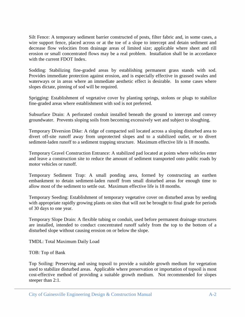
City of Gainesville Engineering Design & Construction Manual A-2
Silt Fence: A temporary sediment barrier constructed of posts, filter fabric and, in some cases, a wire support fence, placed across or at the toe of a slope to intercept and detain sediment and decrease flow velocities from drainage areas of limited size; applicable where sheet and rill erosion or small concentrated flows may be a real problem. Installation shall be in accordance with the current FDOT Index.
Sodding: Stabilizing fine-graded areas by establishing permanent grass stands with sod. Provides immediate protection against erosion, and is especially effective in grassed swales and waterways or in areas where an immediate aesthetic effect is desirable. In some cases where slopes dictate, pinning of sod will be required.
Sprigging: Establishment of vegetative cover by planting springs, stolons or plugs to stabilize fine-graded areas where establishment with sod is not preferred.
Subsurface Drain: A perforated conduit installed beneath the ground to intercept and convey groundwater. Prevents sloping soils from becoming excessively wet and subject to sloughing.
Temporary Diversion Dike: A ridge of compacted soil located across a sloping disturbed area to divert off-site runoff away from unprotected slopes and to a stabilized outlet, or to divert sediment-laden runoff to a sediment trapping structure. Maximum effective life is 18 months.
Temporary Gravel Construction Entrance: A stabilized pad located at points where vehicles enter and leave a construction site to reduce the amount of sediment transported onto public roads by motor vehicles or runoff.
Temporary Sediment Trap: A small ponding area, formed by constructing an earthen embankment to detain sediment-laden runoff from small disturbed areas for enough time to allow most of the sediment to settle out. Maximum effective life is 18 months.
Temporary Seeding: Establishment of temporary vegetative cover on disturbed areas by seeding with appropriate rapidly growing plants on sites that will not be brought to final grade for periods of 30 days to one year.
Temporary Slope Drain: A flexible tubing or conduit, used before permanent drainage structures are installed, intended to conduct concentrated runoff safely from the top to the bottom of a disturbed slope without causing erosion on or below the slope. TMDL: Total Maximum Daily Load TOB: Top of Bank Top Soiling: Preserving and using topsoil to provide a suitable growth medium for vegetation used to stabilize disturbed areas. Applicable where preservation or importation of topsoil is most cost-effective method of providing a suitable growth medium. Not recommended for slopes steeper than 2:1.
City of Gainesville Engineering Design & Construction Manual A-3
Tree Preservation and Protection: Protecting existing trees from mechanical and other injury during land disturbing and construction activity to insure the survival of desirable trees where they will be effective for erosion and sediment control and provide other environmental and aesthetic benefit.
Trees, Shrubs, Vines, and Ground Covers: Stabilizing disturbed areas by planting trees, shrubs, vines and ground covers where turf is not preferred. These plant materials also provide food and shelter for wildlife as well as many other environmental benefits. Especially effective where plants are desirable and turf maintenance is difficult.
Vegetative Streambank Stabilization: The establishment of appropriate vegetation to protect the banks from erosion.

APPENDIX B Standard Details
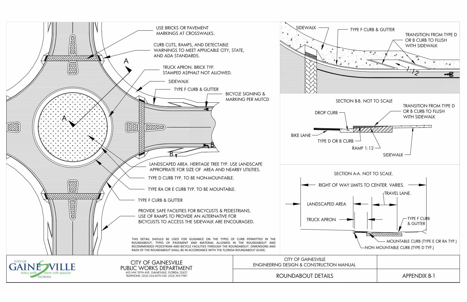
TYPE D CURB TYP. TO BE NON-MOUNTABLE.
TYPE RA OR E CURB TYP. TO BE MOUNTABLE.
TYPE F CURB & GUTTER
TRUCK APRON. BRICK TYP.STAMPED ASPHALT NOT ALLOWED.
LANDSCAPED AREA. HERITAGE TREE TYP. USE LANDSCAPEAPPROPRIATE FOR SIZE OF AREA AND NEARBY UTILITIES.
CURB CUTS, RAMPS, AND DETECTABLEWARNINGS TO MEET APPLICABLE CITY, STATE,AND ADA STANDARDS.
USE BRICKS OR PAVEMENTMARKINGS AT CROSSWALKS.
PROVIDE SAFE FACILITIES FOR BICYCLISTS & PEDESTRIANS.USE OF RAMPS TO PROVIDE AN ALTERNATIVE FORBICYCLISTS TO ACCESS THE SIDEWALK ARE ENCOURAGED.
TYPE F CURB & GUTTER
SIDEWALK
BICYCLE SIGNING &MARKING PER MUTCD
RIGHT OF WAY LIMITS TO CENTER. VARIES.
LANDSCAPED AREA
TRUCK APRON
TRAVEL LANE.
NON MOUNTABLE CURB (TYPE D TYP.)MOUNTABLE CURB (TYPE E OR RA TYP.)
TYPE F CURB& GUTTER
APPENDIX B-1
CITY OF GAINESVILLEENGINEERING DESIGN & CONSTRUCTION MANUAL
ROUNDABOUT DETAILS
CITY OF GAINESVILLEPUBLIC WORKS DEPARTMENT
405 NW 39TH AVE. GAINESVILLE, FLORIDA 32627TELEPHONE: (352) 334-5070 FAX: (352) 393-7987
SECTION B-B. NOT TO SCALE
A
A
THIS DETAIL SHOULD BE USED FOR GUIDANCE ON THE TYPES OF CURB PERMITTED IN THEROUNDABOUT, TYPES OF PAVEMENT AND MATERIAL ALLOWED IN THE ROUNDABOUT ANDRECOMMENDED PEDESTRIAN AND BICYCLE FACILITIES THROUGH THE ROUNDABOUT. DIMENSIONS ANDRADII OF THE ROUNDABOUT SHALL BE IN ACCORDANCE WITH THE FLORIDA ROUNDABOUT GUIDE.
BB
SECTION A-A. NOT TO SCALE.
SIDEWALK TYPE F CURB & GUTTERTRANSITION FROM TYPE DOR B CURB TO FLUSHWITH SIDEWALK
1:12
BIKE LANE
DROP CURB
TYPE D OR B CURB
RAMP 1:12SIDEWALK
TRANSITION FROM TYPE DOR B CURB TO FLUSHWITH SIDEWALK
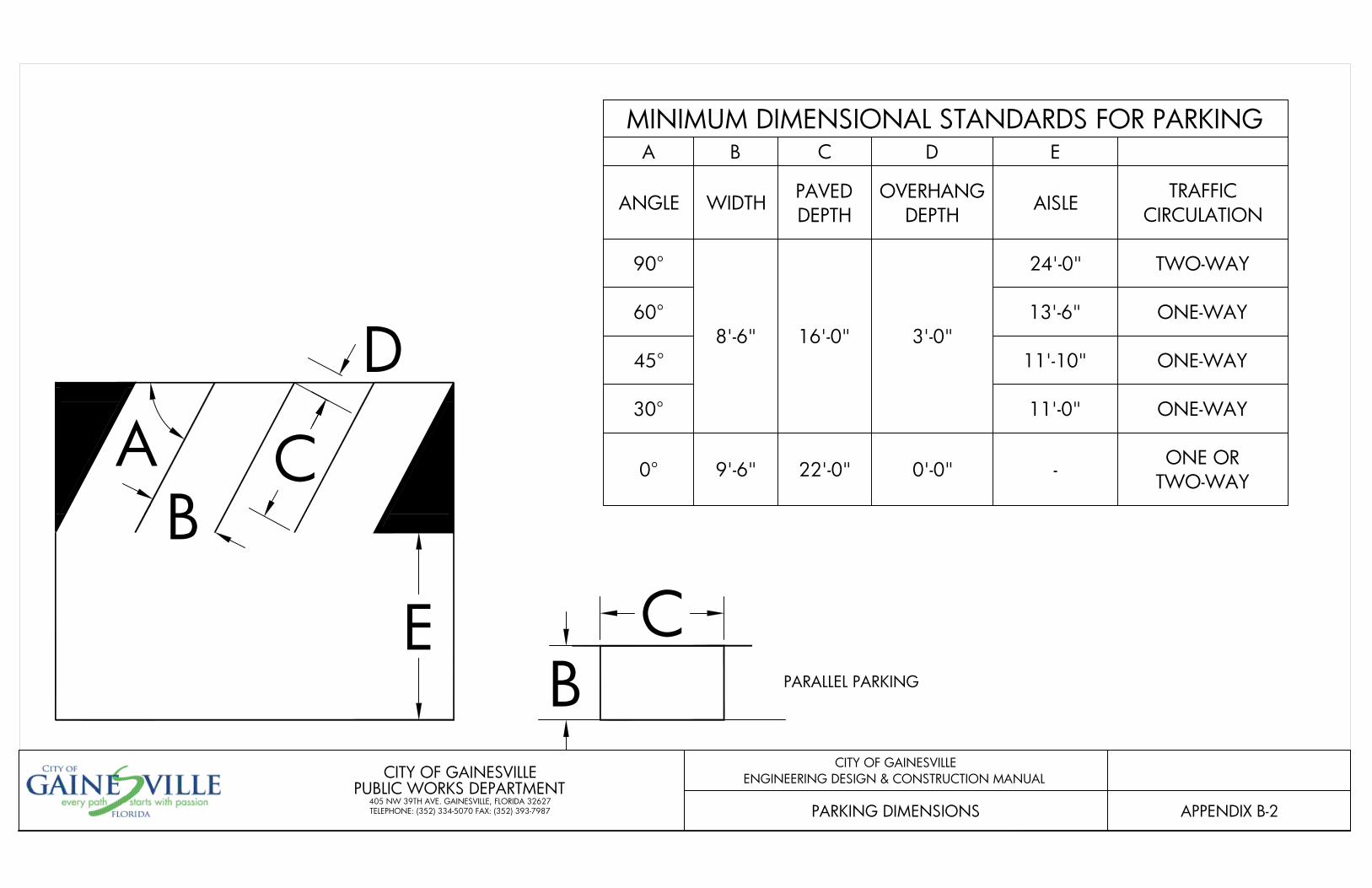
E
AB
C
BC
D
APPENDIX B-2
CITY OF GAINESVILLEENGINEERING DESIGN & CONSTRUCTION MANUAL
PARKING DIMENSIONS
CITY OF GAINESVILLEPUBLIC WORKS DEPARTMENT
405 NW 39TH AVE. GAINESVILLE, FLORIDA 32627TELEPHONE: (352) 334-5070 FAX: (352) 393-7987
MINIMUM DIMENSIONAL STANDARDS FOR PARKINGA B C D E
ANGLE WIDTH PAVEDDEPTH
OVERHANGDEPTH AISLE TRAFFIC
CIRCULATION
90°
8'-6" 16'-0" 3'-0"
24'-0" TWO-WAY
60° 13'-6" ONE-WAY
45° 11'-10" ONE-WAY
30° 11'-0" ONE-WAY
0° 9'-6" 22'-0" 0'-0" - ONE ORTWO-WAY
PARALLEL PARKING
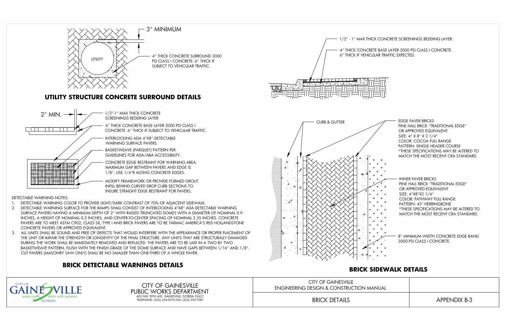
APPENDIX B-3
CITY OF GAINESVILLEENGINEERING DESIGN & CONSTRUCTION MANUAL
BRICK DETAILS
CITY OF GAINESVILLEPUBLIC WORKS DEPARTMENT
405 NW 39TH AVE. GAINESVILLE, FLORIDA 32627TELEPHONE: (352) 334-5070 FAX: (352) 393-7987
INNER PAVER BRICKSPINE HALL BRICK "TRADITIONAL EDGE"OR APPROVED EQUIVALENTSIZE: 4"X8"X2 1/4"COLOR: PATHWAY FULL RANGEPATTERN: 45° HERRINGBONE*THESE SPECIFICATIONS MAY BE ALTERED TOMATCH THE MOST RECENT CRA STANDARD.
EDGE PAVER BRICKSPINE HALL BRICK "TRADITIONAL EDGE"OR APPROVED EQUIVALENTSIZE: 4" X 8" X 2 1/4"COLOR: COCOA FULL RANGEPATTERN: SINGLE HEADER COURSE*THESE SPECIFICATIONS MAY BE ALTERED TOMATCH THE MOST RECENT CRA STANDARD.
8" MINIMUM WIDTH CONCRETE EDGE BAND3000 PSI CLASS I CONCRETE.
CURB & GUTTER
1/2" - 1" MAX THICK CONCRETE SCREENINGS BEDDING LAYER.
4" THICK CONCRETE BASE LAYER 3000 PSI CLASS I CONCRETE.6" THICK IF VEHICULAR TRAFFIC EXPECTED.
BRICK SIDEWALK DETAILS
1/2"-1" MAX THICK CONCRETESCREENINGS BEDDING LAYER
2" MIN.
4" THICK CONCRETE BASE LAYER 3000 PSI CLASS ICONCRETE. 6" THICK IF SUBJECT TO VEHICULAR TRAFFIC.
INTERLOCKING ADA 4"X8" DETECTABLEWARNING SURFACE PAVERS.
BASKETWEAVE (PARQUET) PATTERN PERGUIDELINES FOR ADA/ABA ACCESSIBILITY.
CONCRETE EDGE RESTRAINT FOR WARNING AREA.MAXIMUM GAP BETWEEN PAVERS AND EDGE IS1/8". USE 1/4"R ALONG CONCRETE EDGES.
MODIFY FRAMEWORK OR PROVIDE FORMED GROUTINFILL BEHIND CURVED DROP CURB SECTIONS TOINSURE STRAIGHT EDGE RESTRAINT FOR PAVERS.
DETECTABLE WARNING NOTES:1. DETECTABLE WARNING COLOR TO PROVIDE LIGHT/DARK CONTRAST OF 70% OF ADJACENT SIDEWALK.2. DETECTABLE WARNING SURFACE FOR THE RAMPS SHALL CONSIST OF INTERLOCKING 4"X8" ADA DETECTABLE WARNING
SURFACE PAVERS HAVING A MINIMUM DEPTH OF 2" WITH RAISED TRUNCATED DOMES WITH A DIAMETER OF NOMINAL 0.9INCHES, A HEIGHT OF NOMINAL 0.2 INCHES, AND CENTER-TO-CENTER SPACING OF NOMINAL 2.35 INCHES. CONCRETEPAVERS ARE TO MEET ASTM C902, CLASS SX, TYPE I AND BRICK PAVERS ARE TO BE TARMAC AMERICA'S RED HOLLANDSTONECONCRETE PAVERS OR APPROVED EQUIVALENT.
3. ALL UNITS SHALL BE SOUND AND FREE OF DEFECTS THAT WOULD INTERFERE WITH THE APPEARANCE OR PROPER PLACEMENT OFTHE UNIT OR IMPAIR THE STRENGTH OR LONGEVITY OF THE FINAL STRUCTURE. ANY UNITS THAT ARE STRUCTURALLY DAMAGEDDURING THE WORK SHALL BE IMMEDIATELY REMOVED AND REPLACED. THE PAVERS ARE TO BE LAID IN A TWO BY TWOBASKETWEAVE PATTERN, FLUSH WITH THE FINISH GRADE OF THE DOME SURFACE AND HAVE GAPS BETWEEN 1/16" AND 1/8".CUT PAVERS (MASONRY SAW ONLY) SHALL BE NO SMALLER THAN ONE-THIRD OF A WHOLE PAVER.
UTILITY STRUCTURE CONCRETE SURROUND DETAILS
BRICK DETECTABLE WARNINGS DETAILS
UTILITY
3" MINIMUM
4" THICK CONCRETE SURROUND 3000PSI CLASS I CONCRETE. 6" THICK IFSUBJECT TO VEHICULAR TRAFFIC.
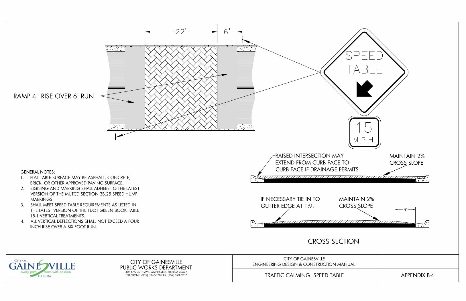
RAISED INTERSECTION MAYEXTEND FROM CURB FACE TOCURB FACE IF DRAINAGE PERMITS
CROSS SECTION
MAINTAIN 2%CROSS SLOPE
IF NECESSARY TIE IN TOGUTTER EDGE AT 1:9.
MAINTAIN 2%CROSS SLOPE
RAMP 4" RISE OVER 6' RUN
APPENDIX B-4
CITY OF GAINESVILLEENGINEERING DESIGN & CONSTRUCTION MANUAL
TRAFFIC CALMING: SPEED TABLE
CITY OF GAINESVILLEPUBLIC WORKS DEPARTMENT
405 NW 39TH AVE. GAINESVILLE, FLORIDA 32627TELEPHONE: (352) 334-5070 FAX: (352) 393-7987
GENERAL NOTES:1. FLAT TABLE SURFACE MAY BE ASPHALT, CONCRETE,
BRICK, OR OTHER APPROVED PAVING SURFACE.2. SIGNING AND MARKING SHALL ADHERE TO THE LATEST
VERSION OF THE MUTCD SECTION 3B.25 SPEED HUMPMARKINGS.
3. SHALL MEET SPEED TABLE REQUIREMENTS AS LISTED INTHE LATEST VERSION OF THE FDOT GREEN BOOK TABLE15-1 VERTICAL TREATMENTS.
4. ALL VERTICAL DEFLECTIONS SHALL NOT EXCEED A FOURINCH RISE OVER A SIX FOOT RUN.
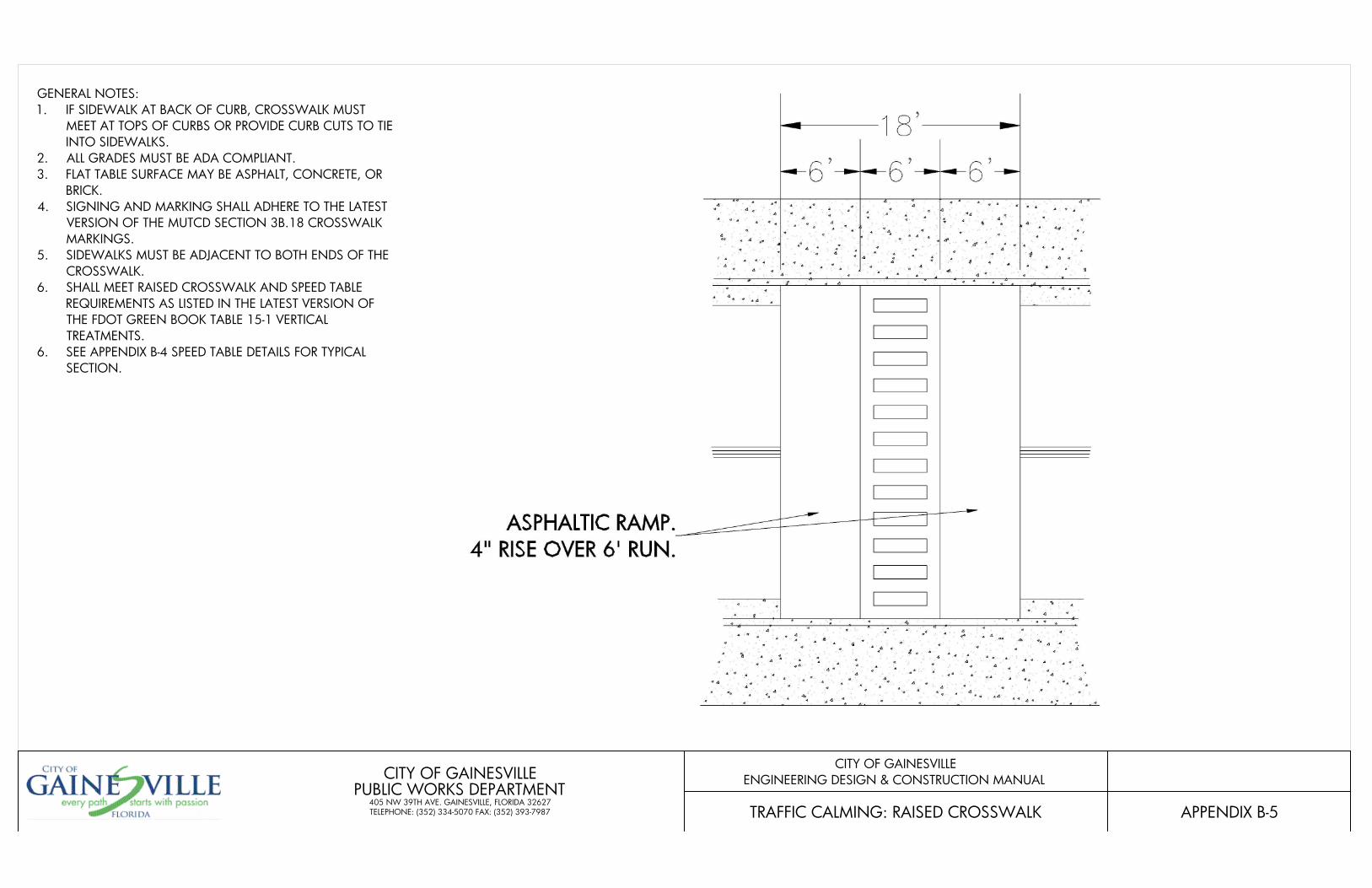
APPENDIX B-5
CITY OF GAINESVILLEENGINEERING DESIGN & CONSTRUCTION MANUAL
TRAFFIC CALMING: RAISED CROSSWALK
CITY OF GAINESVILLEPUBLIC WORKS DEPARTMENT
405 NW 39TH AVE. GAINESVILLE, FLORIDA 32627TELEPHONE: (352) 334-5070 FAX: (352) 393-7987
GENERAL NOTES:1. IF SIDEWALK AT BACK OF CURB, CROSSWALK MUST
MEET AT TOPS OF CURBS OR PROVIDE CURB CUTS TO TIEINTO SIDEWALKS.
2. ALL GRADES MUST BE ADA COMPLIANT.3. FLAT TABLE SURFACE MAY BE ASPHALT, CONCRETE, OR
BRICK.4. SIGNING AND MARKING SHALL ADHERE TO THE LATEST
VERSION OF THE MUTCD SECTION 3B.18 CROSSWALKMARKINGS.
5. SIDEWALKS MUST BE ADJACENT TO BOTH ENDS OF THECROSSWALK.
6. SHALL MEET RAISED CROSSWALK AND SPEED TABLEREQUIREMENTS AS LISTED IN THE LATEST VERSION OFTHE FDOT GREEN BOOK TABLE 15-1 VERTICALTREATMENTS.
6. SEE APPENDIX B-4 SPEED TABLE DETAILS FOR TYPICALSECTION.
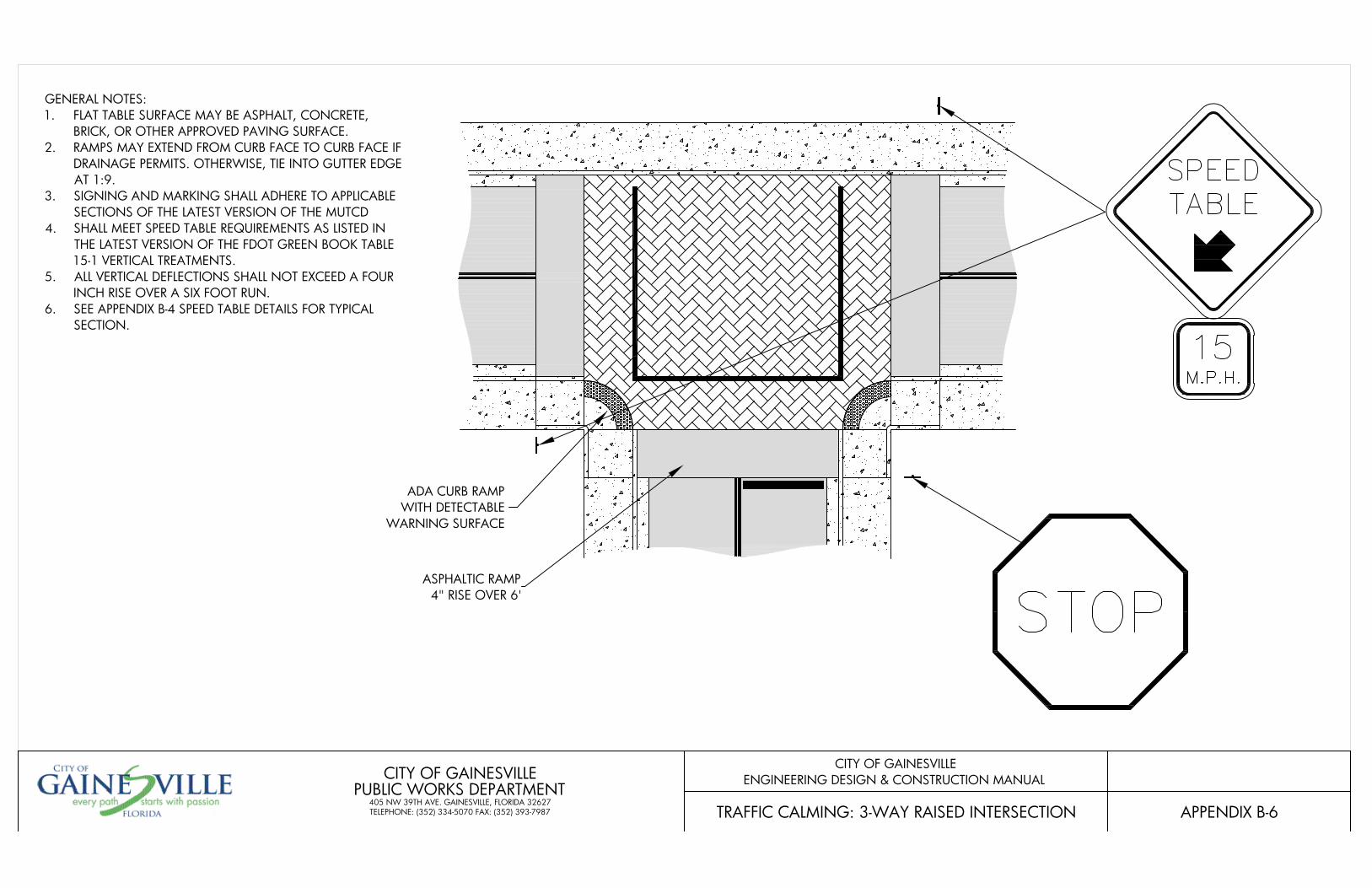
ADA CURB RAMPWITH DETECTABLE
WARNING SURFACE
ASPHALTIC RAMP4" RISE OVER 6'
APPENDIX B-6
CITY OF GAINESVILLEENGINEERING DESIGN & CONSTRUCTION MANUAL
TRAFFIC CALMING: 3-WAY RAISED INTERSECTION
CITY OF GAINESVILLEPUBLIC WORKS DEPARTMENT
405 NW 39TH AVE. GAINESVILLE, FLORIDA 32627TELEPHONE: (352) 334-5070 FAX: (352) 393-7987
GENERAL NOTES:1. FLAT TABLE SURFACE MAY BE ASPHALT, CONCRETE,
BRICK, OR OTHER APPROVED PAVING SURFACE.2. RAMPS MAY EXTEND FROM CURB FACE TO CURB FACE IF
DRAINAGE PERMITS. OTHERWISE, TIE INTO GUTTER EDGEAT 1:9.
3. SIGNING AND MARKING SHALL ADHERE TO APPLICABLESECTIONS OF THE LATEST VERSION OF THE MUTCD
4. SHALL MEET SPEED TABLE REQUIREMENTS AS LISTED INTHE LATEST VERSION OF THE FDOT GREEN BOOK TABLE15-1 VERTICAL TREATMENTS.
5. ALL VERTICAL DEFLECTIONS SHALL NOT EXCEED A FOURINCH RISE OVER A SIX FOOT RUN.
6. SEE APPENDIX B-4 SPEED TABLE DETAILS FOR TYPICALSECTION.
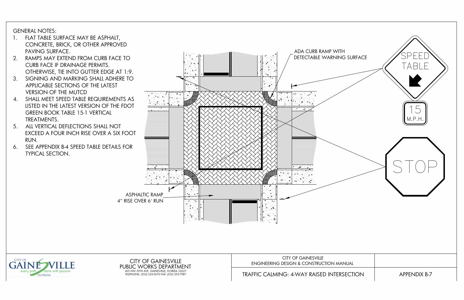
ADA CURB RAMP WITHDETECTABLE WARNING SURFACE
ASPHALTIC RAMP4" RISE OVER 6' RUN
APPENDIX B-7
CITY OF GAINESVILLEENGINEERING DESIGN & CONSTRUCTION MANUAL
TRAFFIC CALMING: 4-WAY RAISED INTERSECTION
CITY OF GAINESVILLEPUBLIC WORKS DEPARTMENT
405 NW 39TH AVE. GAINESVILLE, FLORIDA 32627TELEPHONE: (352) 334-5070 FAX: (352) 393-7987
GENERAL NOTES:1. FLAT TABLE SURFACE MAY BE ASPHALT,
CONCRETE, BRICK, OR OTHER APPROVEDPAVING SURFACE.
2. RAMPS MAY EXTEND FROM CURB FACE TOCURB FACE IF DRAINAGE PERMITS.OTHERWISE, TIE INTO GUTTER EDGE AT 1:9.
3. SIGNING AND MARKING SHALL ADHERE TOAPPLICABLE SECTIONS OF THE LATESTVERSION OF THE MUTCD
4. SHALL MEET SPEED TABLE REQUIREMENTS ASLISTED IN THE LATEST VERSION OF THE FDOTGREEN BOOK TABLE 15-1 VERTICALTREATMENTS.
5. ALL VERTICAL DEFLECTIONS SHALL NOTEXCEED A FOUR INCH RISE OVER A SIX FOOTRUN.
6. SEE APPENDIX B-4 SPEED TABLE DETAILS FORTYPICAL SECTION.
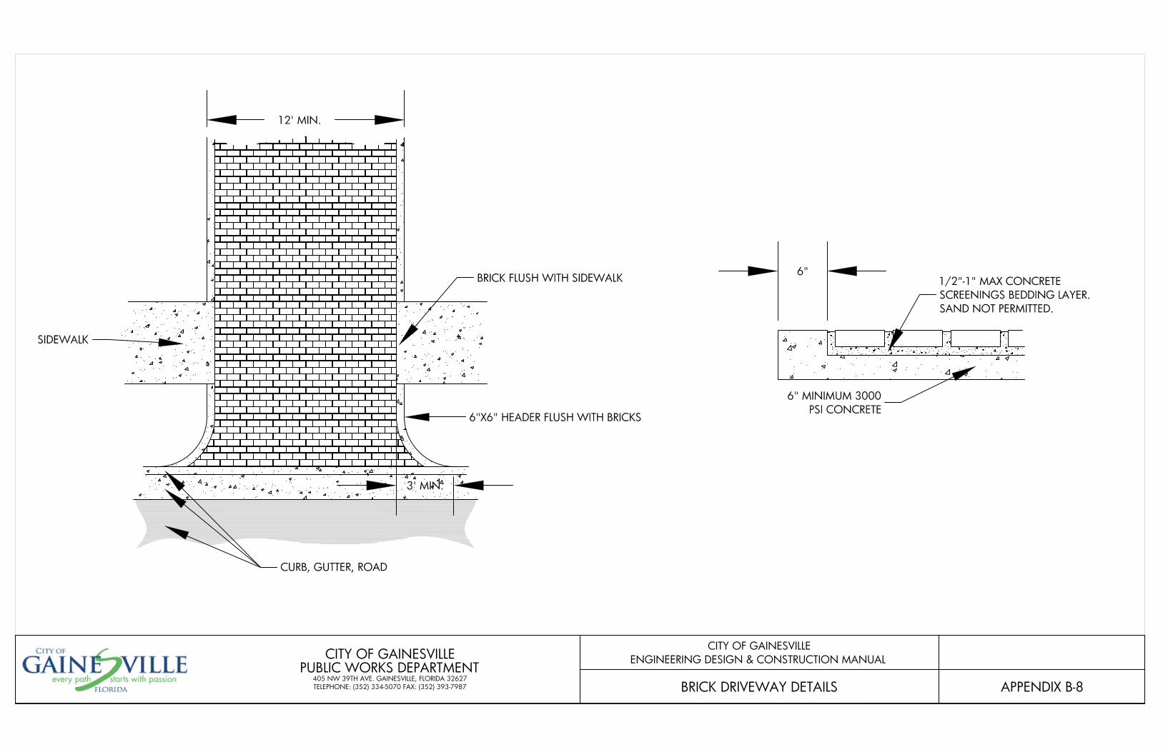
APPENDIX B-8
CITY OF GAINESVILLEENGINEERING DESIGN & CONSTRUCTION MANUAL
BRICK DRIVEWAY DETAILS
CITY OF GAINESVILLEPUBLIC WORKS DEPARTMENT
405 NW 39TH AVE. GAINESVILLE, FLORIDA 32627TELEPHONE: (352) 334-5070 FAX: (352) 393-7987
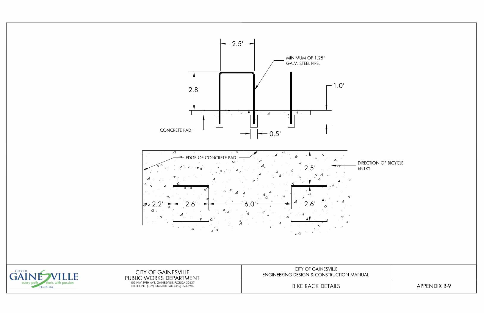
2.8'
0.5'
2.5'
1.0'
MINIMUM OF 1.25"GALV. STEEL PIPE.
CONCRETE PAD
DIRECTION OF BICYCLEENTRY
2.6'6.0'
EDGE OF CONCRETE PAD
2.6'2.2'
2.5'
APPENDIX B-9
CITY OF GAINESVILLEENGINEERING DESIGN & CONSTRUCTION MANUAL
BIKE RACK DETAILS
CITY OF GAINESVILLEPUBLIC WORKS DEPARTMENT
405 NW 39TH AVE. GAINESVILLE, FLORIDA 32627TELEPHONE: (352) 334-5070 FAX: (352) 393-7987
![Gainesville Daily Sun. (Gainesville, Florida) 1908-03-26 [p 8].ufdcimages.uflib.ufl.edu/UF/00/02/82/98/01246/00858.pdfsilo 0G Cow city city city tied hat of bf OC city city Ibe city](https://img.pdfslide.net/doc/110x75/60a24d812fd6db557e56a0f7/gainesville-daily-sun-gainesville-florida-1908-03-26-p-8-silo-0g-cow-city.jpg)