Embed Size (px)
Citation preview
25/10/a Revision 2 Hoja 1 de 30
HIMOINSA S.L. ELECTRONIC R&D DEPARTMENT
CONTROL, PROTECTION AND
VISUALIZATION ELECTRONIC MANUAL CEN-
TRALITE FOR GENERATING SETS
CMD2.0
25/10/a Revision 2 Hoja 2 de 30
HIMOINSA S.L. ELECTRONIC R&D DEPARTMENT
0. - CONTENTS.
1. DESCRIPTION AND GENERAL CHARACTERISTICS ..................... Page 3 2. INSTALLATION MATERIALS ....................................................... Page 4 3. FRONT PANEL ....................................................... Page 5 4. OPERATIONAL MODES ....................................................... Page 7
Manual mode ....................................................... Page 7 Automatic mode ....................................................... Page 7
Stop mode ........................................................ Page 7 Low consumption mode ............................................ Page 7
5. DESCRIPTION OF THE CONNECTING TERMINALS. GENERAL CONNECTIONS SCHEME ............................................ Page 9 6. PARAMETERS, DESCRIPTION AND PROGRAMMING ..................... Page 12 7. CALIBRATING & ANALOGICAL READINGS ADJUSTMENT ............ Page 20 8. ALARMS AND ALARMS CODE ....................................................... Page 21 9. TECHNICAL DATA ....................................................... Page 24
25/10/a Revision 2 Hoja 3 de 30
HIMOINSA S.L. ELECTRONIC R&D DEPARTMENT
1. DESCRIPTION AND GENERAL CHARACTERISTICS
The protection switchboard is cased in an insulating box which keeps off electro-
magnetic radiations. It includes visualization of electrical parameters and optical signals.
This device integrates the possibility of starting the motor in a manual or automa-
tic way (by free voltage contact), and protecting it from possible breakdowns during ope-
ration. Management is effected in the interior, through an electronic circuit controlled by
microprocessor.
The general characteristics are the following:
• Voltage supply 12/24V.
• Protections:
o Overvoltage o Subvoltage o Asymmetry o Overcurrent o Overfrequency (overspeed) o Subfrequency (loss of speed) o Etc.
• Automatic filling of fuel tank.
• Readings:
o Voltages o Currents o Fuel level o Pressure o Temperature o Battery voltage o Hour counter o Tachometer (R.P.M. indicator) o Frequency
• Start by free voltage contact.
• Possibility of programming the type of action to accomplish after an
alarm.
• 3-phase set sensor.
25/10/a Revision 2 Hoja 4 de 30
HIMOINSA S.L. ELECTRONIC R&D DEPARTMENT
2. INSTALLATION MATERIALS
The following elements are necessary for the complete installation of the CMD2.0
device in a generating set:
- Cmd2.0.
- 3 current transformers /5Aac.
- Oil pressure sensor (vdo code 360.081/030/009).
- Water temperature sensor (vdo code 323.803/004/001).
- Level sensor ( variable resistance gauger 0 to 330 ohm).
- Thermostat.
- Pressurestat.
- Relay boards 802ctreles02-12/24 and 802ctreles02-12/24s.
IMPORTANT: Before carrying out any tasks on the current transformers, verify
that no current is circulating in the primary transformer, since if we open the se-
condary of an current transformer through which a current is circulating, extreme-
ly high voltages are produced, which can injure or even kill the person manipula-
ting them.
Installation must be accomplished by qualified specialist technicians in
strict observance of all electrical regulation codes applicable.
Wiring connections to the battery of the motor should be accomplished by means
of two 2.5 mm2conducting cables.
In noisy environments (i.e., gas motors with high voltage ignitions, etc), the battery
wiring must be a 2.5 mm2 twisted pair.
25/10/a Revision 2 Hoja 5 de 30
HIMOINSA S.L. ELECTRONIC R&D DEPARTMENT
3. FRONT PANEL.
In addition to an alarm codes chart, the following elements are found on the frontal part of
the CMD2.0 protection, control and visualization device:
Start switch
V(↑).
To select the voltage that will be visualized in display 1. The switchboard shows the volt-
ages between phases of the generating set: L1-L2 (VRS), L2-L3(VST), L3-L1(VTR).
A(+).
To select the current measure showed in display 2. The switchboard offers currents
readings of the three phases (IL1, IL2, IL3).
D3(↓).
To select, from four possible measures (frequency reading, battery voltage, fuel level or
alarm code), the measure to be visualized in display 3.
D4(-).
Similarly to D3, D4 permits to choose which of the four measures offered by display 4 to
visualize (hour counter, revolutions counter, water temperature, oil pressure).
AUT operation mode.
To select the automatic operation mode.
STOP/RESET operation mode.
To select the STOP operation mode. By maintaining this button pressed for 5 seconds,
the centralite executes a reset operation.
START/MAN operation mode.
Starts the motor and selects the manual operation mode.
25/10/a Revision 2 Hoja 6 de 30
HIMOINSA S.L. ELECTRONIC R&D DEPARTMENT
The following optical signals can also be found in the front panel:
Indicative LEDs of current measure. These leds inform of the measure shown in each
display.
Operation mode lamps. Indicate the current operation mode of the switchboard (auto-
matic, stop, manual, low consumption).
Stop cycle. This led will light up when the switchboard orders a stop cycle and will not be
turned off until the stop cycle is completed. The length of the stop cycle is determined by
parameters P12 and P13.
Warm-up. This led lights up to signal that the switchboard orders a warm-up. An acoustic
alarm will notify the immediate start of the set.
Motor ON. Indicates that the motor is started. This is fulfilled when the voltage in any
phase is superior to the threshold established by parameter P14, if a sign in the voltage
entry of the battery charge alternator is superior to the value indicated by parameter P15,
or when the Pick-Up Frequency of the motor is superior to the one indicated by parame-
ter P16.
LT closed. This signal is active when the free voltage contact is closed and is turned off
when the free voltage contact is open. In automatic mode, when the LT is closed, the
switchboard will begin the start cycle. In STOP mode there will not be no change in the
state of the switchboard.
Load. This indicator is lit up upon closing the set contactor, thus indicating that the set is
working with the load. The stabilization and warm-up times of the set before activating the
load are defined by parameter P11.
25/10/a Revision 2 Hoja 7 de 30
HIMOINSA S.L. ELECTRONIC R&D DEPARTMENT
4. OPERATIONAL MODES.
To obtain optimum performance of the set the following aspects must be emp-
hasized:
- If the magnetic Pick-Up is installed, it should be indicated (by setting parame-
ter P34 to "1"), that the frequency reading will be accomplished by Pick-Up. If
the frequency reading is done by generator, the magnetic Pick-Up must not be
connected to the switchboard.
- The switchboard has three ways of detecting a started motor: by voltage in the
phases of the generator, by voltage in the battery load alternator and by the
frequency of the motor Pick-Up. The switchboard detects that the motor is
started if the voltage in any phase is superior to the threshold established in
parameter P14, when a sign in the voltage entry of the battery load alternator
is superior to the value indicated in parameter P15, or if the frequency of the
motor Pick-Up is superior to the frequency indicated by parameter P16.
- The stop cycle is accomplished by observing the times established by para-
meters P12 and P13: the switchboard will order a stop until the stop time by
excitement (P13) is accomplished, even if the set is already stopped.
The centralite can operate in four different modes, which can be selected via the
AUT, STOP/RESET, MAN/START switches:
Manual mode (MAN/START). In this function the set can be started manually through
the MAN/STARTswitch. The protections of the motor are active at all times. The connec-
tion with the load (close set contactor) is accomplished automatically, after a delay time
for the stabilization of the set; this time is definable by the user (parameter P11). From
that moment on, the set contactor remains permanently locked, until a set stop is per-
formed, or an alarm with an associated stop is detected.
Automatic mode (AUT). In this function the start depends on the closing of the free vol-
tage contact LT. When this is closed, the centralite will order sequentially the start at-
tempts indicated by parameter P09, with the length indicated by parameter P08, and with
a waiting period between start attempts indicated by parameter P10.
25/10/a Revision 2 Hoja 8 de 30
HIMOINSA S.L. ELECTRONIC R&D DEPARTMENT
Stop mode (STOP/RESET). In this mode, the generating set is stopped and remains
waiting for a mode change. When maintained pressed for 5 seconds, the STOP/RESET
button will accomplish a reset.
Low power mode. The switchboard engages this operation mode after 5 minutes on
non-activity in mode stop, or when in automatic mode with the LT open for more than 5
minutes. In low power mode, the displays and the leds will turn off, except the
STOP/RESET led (blinking). To exit this mode, just press any button of the switchboard.
Note: after disconnection or feed failure, the switchboard may begin to operate,
once the feed is re-established, in either automatic or stop mode (as programmed by
parameter P01).
The handling of displays showing the measures done by the switchboard is the
same for the first 3 modes. To go from one measure to another, simply press the button
associated with each of them, and the led lighting up in the left-hand side of the display
will indicate the measure that it is being currently visualized.

25/10/a Revision 2 Hoja 9 de 30
HIMOINSA S.L. ELECTRONIC R&D DEPARTMENT
The following figure shows the operation blocks of the CMD switchboard.
SWITCH ON
TEST
Automatic Mode Stop Mode
Low PowerMode
START
CHECK
VISUALIZATION
STOP
¿ALARM ?
Yes
No
RESET
Manual Mode
25/10/a Revision 2 Hoja 10 de 30
HIMOINSA S.L. ELECTRONIC R&D DEPARTMENT
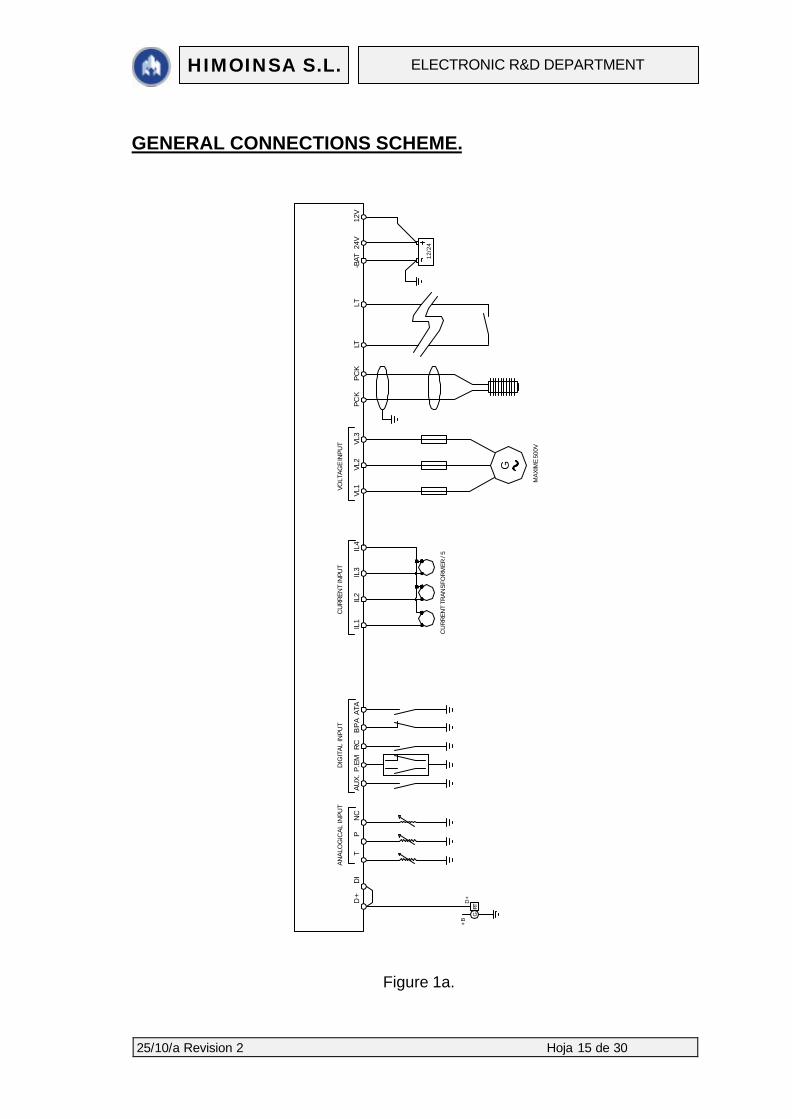
5. DESCRIPTION OF THE CONNECTING TERMINALS,GENERAL
CONNECTIONS SCHEME.
The connection terminals are placed on the back panel of the switchboard (first
see figures 1a and 1b below).
12V terminal: battery positive 12V. The positive of the battery (if it is a 12V one) is con-
nected to this terminal.
24V terminal: battery positive 24V. The positive of the battery (if it is a 24V one) is con-
nected to this terminal.
BAT terminal: battery negative. The negative of the battery is connected to this termi-
nal.
Note: in environments with high electromagnetic interferences, the battery must be
directly wired by a 2.5 mm2 twisted pair.
LT and LT terminal: Free voltage contact. a contact without voltage is connected to
these terminals, only operative in automatic mode. If the contact passes to CLOSE posi-
tion, the genset starts, if it passes to OPEN, the genset stops.
PCK and PCK terminal: pick-up input. The signal from the magnetic pick-up is con-
nected to these terminals. If the set is provided with a pick-up device, parameter P34
must be set to "1", so that the frequency reading is accomplished through the pick-up.
These inputs do not have polarity.
VL1, VL2 and VL3 terminals: generator input voltage. The phases of the alternator
are connected to these terminals. The permitted maximum is 500V rms. We can have 4
different systems, programmable via parameter P04. The 4 systems are: system without
phases (i.e., motor pump), monophase system, two-phase system and three-phase sys-
tem. In monophase systems, we must connect between terminals VL1 and VL2; if it is 2-
25/10/a Revision 2 Hoja 11 de 30
HIMOINSA S.L. ELECTRONIC R&D DEPARTMENT
phase, we will connect the two phases to VL1, VL2 and the neutral or common to VL3, if
it is a 3-phase system, we will connect the three phases to VL1, VL2 and VL3.
IL1, IL2, IL3 and N terminals: current input /5. The secondaries of the current trans-
formers ( /5A) must be connected to the current inputs IL1, IL2, IL3, the common conduc-
tor of the secondaries of the current transformers must be connected to terminal N, as
indicated in figure 1a. These transformers will have a power superior to 1.5 VA. The
transformation ratio is indicated by parameter P05.
IMPORTANT: Before carrying out any tasks on the current transformers, verify
that no current is circulating in the primary transformer, since if we open the se-
condary of an current transformer through which a current is circulating, extreme-
ly high voltages are produced, which can injure or even kill the person manipula-
ting them.
NC terminal: fuel level. The fuel level sensor (gauger) is connected to this input. ( va-
riable resistance of 0 to 330 Ohm).
P terminal: oil pressure. The oil pressure sensor is connected to this input (VDO code
360.081/030/009).
T terminal: water temperature. The water temperature sensor is connected to
this input (VDO code 323.803/004/001).
DI terminal: voltage level of the battery load alternator. Terminal D+ of the batte-
ry load alternator is connected to this input and is used to detect whether the battery load
alternator is re-charging the battery. In case of failure detection, the type of action to ac-
complish can be programmed in the battery load alternator through parameter P24. Furt-
hermore, this input can also detect whether the generating set is running.
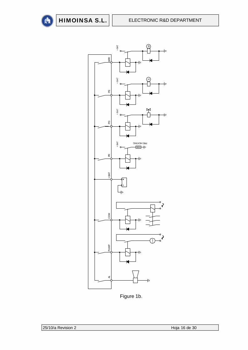
ARR terminal: start. If a start of the motor is internally ordered, this output will activate
for a maximum time programmed by P08; if the motor is found to be running during this
25/10/a Revision 2 Hoja 12 de 30
HIMOINSA S.L. ELECTRONIC R&D DEPARTMENT
time, the output will become inactive. Also, the number of start attempts is programmable
through parameter P09, and the time between them, through P10. An external relay, with
its corresponding diodes for dissipation of inductive currents, is necessary (see figure
1b). This output sustains a maximum current of 0.5A.
PE terminal: stop by excitation. If a stop of the generating set is internally ordered, this
output will activate for a maximum time programmed by P13. If the genset does not stop,
further stops will be ordered for successive periods of equal duration until the genset
stops. An external relay, with its corresponding diodes for dissipation of inductive cu-
rrents, is necessary (see figure 1b). This output sustains a maximum current of 0.5A.
PD terminal: stop by de-excitation. The output associated with this terminal is active
when the genset has to be started and is deactivated when ordered to stop. An external
relay, with its corresponding diodes for dissipation of inductive currents, is necessary
(see figure 1b). This contact sustains a maximum current of 0.5A.
PR terminal: warm-up. The output associated with this terminal is active before each
start attempt during the time programmed by P07 to accomplish the warm-up of the mo-
tor. An external relay, with its corresponding diodes for dissipation of inductive currents,
is necessary (see figure 1b). This contact sustains a maximum current of 0.5A.
+BAT terminal: battery positive for outputs. The positive of the battery is connected
to this terminal. This positive supplies all the outputs from the switchboard, in addition to
serving as a reference for the reading of the battery voltage.
CON terminal: counter activation (warming of the motor). The output associated with
this terminal becomes active after the time programmed by P11, once the centralite de-
tects that the motor has started. It is used for warming up the set without load, before
putting load on it. An external relay, with its corresponding diodes for dissipation of induc-
tive currents, is necessary (see figure 1b). This output sustains a maximum current of
0.5A.
25/10/a Revision 2 Hoja 13 de 30
HIMOINSA S.L. ELECTRONIC R&D DEPARTMENT
PUMP terminal: automatic fill-up of fuel tank. The output associated with this terminal
is active if this option is enabled through parameter P39 (auto-fill enabled) and the fuel
level descends below the value indicated by parameter P40 (minimum fuel level). It is
deactivated when the fuel level surpasses the value indicated in parameter P41 (maxi-
mum fuel level). An external relay, with its corresponding diodes for dissipation of inducti-
ve currents, is necessary (see figure 1b). This output sustains a maximum current of
0.5A.
AL terminal: alarm output. The output associated with this terminal is active when any
anomaly in the set is detected, or there are values out of the range programmed in the
parameters. An external relay, with its corresponding diodes for dissipation of inductive
currents, is necessary (see figure 1b). This contact sustains a maximum currents of
0.5A.
D+ terminal: Excitation of battery load alternator. Terminal D+ of the battery load
alternator of the generating set is connected to this terminal in order to excite the alterna-
tor and make it begin to load the battery.
ATA terminal: high water temperature. The thermostat corresponding to the water
temperature of the motor is connected to this terminal. Both the delay in the checkup
(P19) and the type of action (P20) are programmable. The alarm is active at low level.
BPA terminal: low oil pressure. The pressurestat corresponding to oil pressure of the
motor is connected to this terminal. Both the delay in the checkup (P17) and the type of
action (P18) are programmable. The alarm is active at low level.
RC terminal: fuel reservoir. The fuel reservation contact is connected to this terminal.
The alarm is active at low level. The type of action after detecting low fuel reservoir is
programmable (P23).
P. EM terminal: emergency stop. When active, an immediate stop of the generating set
is performed. It can be activated (parameter P25) either through a normally open contact
(NO) or through a normally closed contact (NC); in the first case, if we want to activate

25/10/a Revision 2 Hoja 14 de 30
HIMOINSA S.L. ELECTRONIC R&D DEPARTMENT
the emergency stop, we will close the contact and we will put a negative on this entry. In
the second case we will open the circuit and we will stop putting ground on the P. EM
terminal.
AUX terminal: Auxiliary digital INPUT. Any sensor which can close a contact when
activated can be connected to this terminal. Both the delay in the checkup (P21) and the
type of action after activating this input (P22) are programmable. The alarm is active at
low level.
25/10/a Revision 2 Hoja 15 de 30
HIMOINSA S.L. ELECTRONIC R&D DEPARTMENT
GENERAL CONNECTIONS SCHEME.
Figure 1a.
BP
AIL
1D
+
G
+B
D+
RT
DI
TP
NC
AUX.
P.EM
RC
ATA
IL2
IL3
IL4
VL1
VL2
VL3
G
PC
KP
CK
LTLT
-BAT
12V
24V
12/2
4
DIG
ITA
L IN
PUT
CU
RR
ENT
INPU
TVO
LTAG
E IN
PUT
MA
XIM
E 50
0V
CU
RR
ENT
TRA
NSF
OR
MER
/ 5
AN
ALO
GIC
AL
INPU
T
25/10/a Revision 2 Hoja 16 de 30
HIMOINSA S.L. ELECTRONIC R&D DEPARTMENT
Figure 1b.
ALPU
MP
CO
M+
BAT
PU
MP
PR
+BA
T
PD
+B
AT
PE
+B
AT S
ARR
+BA
T M
PRE-HEATING
25/10/a Revision 2 Hoja 17 de 30
HIMOINSA S.L. ELECTRONIC R&D DEPARTMENT
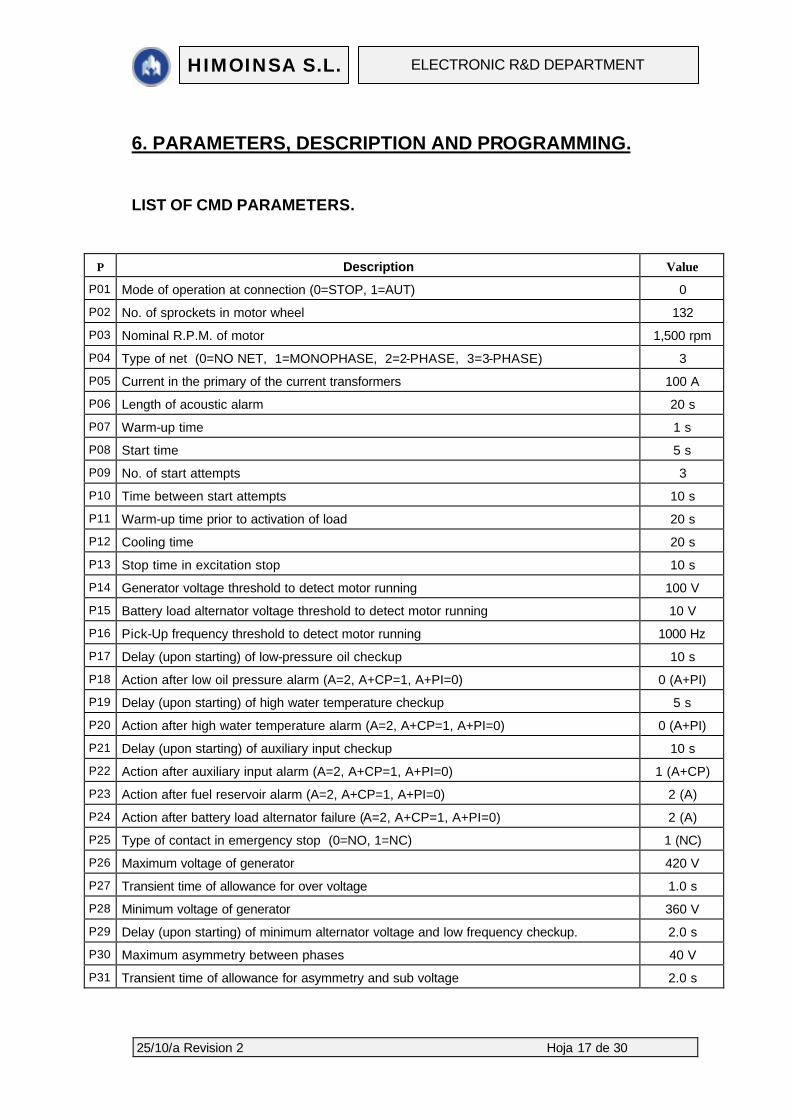
6. PARAMETERS, DESCRIPTION AND PROGRAMMING.
LIST OF CMD PARAMETERS.
P Description Value
P01 Mode of operation at connection (0=STOP, 1=AUT) 0
P02 No. of sprockets in motor wheel 132
P03 Nominal R.P.M. of motor 1,500 rpm
P04 Type of net (0=NO NET, 1=MONOPHASE, 2=2-PHASE, 3=3-PHASE) 3
P05 Current in the primary of the current transformers 100 A
P06 Length of acoustic alarm 20 s
P07 Warm-up time 1 s
P08 Start time 5 s
P09 No. of start attempts 3
P10 Time between start attempts 10 s
P11 Warm-up time prior to activation of load 20 s
P12 Cooling time 20 s
P13 Stop time in excitation stop 10 s
P14 Generator voltage threshold to detect motor running 100 V
P15 Battery load alternator voltage threshold to detect motor running 10 V
P16 Pick-Up frequency threshold to detect motor running 1000 Hz
P17 Delay (upon starting) of low-pressure oil checkup 10 s
P18 Action after low oil pressure alarm (A=2, A+CP=1, A+PI=0) 0 (A+PI)
P19 Delay (upon starting) of high water temperature checkup 5 s
P20 Action after high water temperature alarm (A=2, A+CP=1, A+PI=0) 0 (A+PI)
P21 Delay (upon starting) of auxiliary input checkup 10 s
P22 Action after auxiliary input alarm (A=2, A+CP=1, A+PI=0) 1 (A+CP)
P23 Action after fuel reservoir alarm (A=2, A+CP=1, A+PI=0) 2 (A)
P24 Action after battery load alternator failure (A=2, A+CP=1, A+PI=0) 2 (A)
P25 Type of contact in emergency stop (0=NO, 1=NC) 1 (NC)
P26 Maximum voltage of generator 420 V
P27 Transient time of allowance for over voltage 1.0 s
P28 Minimum voltage of generator 360 V
P29 Delay (upon starting) of minimum alternator voltage and low frequency checkup. 2.0 s
P30 Maximum asymmetry between phases 40 V
P31 Transient time of allowance for asymmetry and sub voltage 2.0 s
25/10/a Revision 2 Hoja 18 de 30
HIMOINSA S.L. ELECTRONIC R&D DEPARTMENT
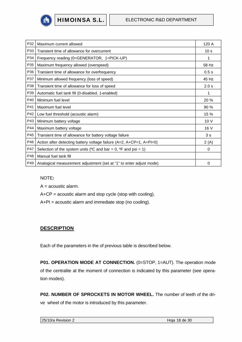
P32 Maximum current allowed 120 A
P33 Transient time of allowance for overcurrent 10 s
P34 Frequency reading (0=GENERATOR, 1=PICK-UP) 1
P35 Maximum frequency allowed (overspeed) 58 Hz
P36 Transient time of allowance for overfrequency 0.5 s
P37 Minimum allowed frequency (loss of speed) 45 Hz
P38 Transient time of allowance for loss of speed 2.0 s
P39 Automatic fuel tank fill (0-disabled, 1-enabled) 1
P40 Minimum fuel level 20 %
P41 Maximum fuel level 90 %
P42 Low fuel threshold (acoustic alarm) 15 %
P43 Minimum battery voltage 10 V
P44 Maximum battery voltage 16 V
P45 Transient time of allowance for battery voltage failure 3 s
P46 Action after detecting battery voltage failure (A=2, A+CP=1, A+PI=0) 2 (A)
P47 Selection of the system units (ºC and bar = 0, ºF and psi = 1) 0
P48 Manual fuel tank fill
P49 Analogical measurement adjustment (set at “1” to enter adjust mode) 0
NOTE:
A = acoustic alarm.
A+CP = acoustic alarm and stop cycle (stop with cooling).
A+PI = acoustic alarm and immediate stop (no cooling).
DESCRIPTION
Each of the parameters in the of previous table is described below.
P01. OPERATION MODE AT CONNECTION. (0=STOP, 1=AUT). The operation mode
of the centralite at the moment of connection is indicated by this parameter (see opera-
tion modes).
P02. NUMBER OF SPROCKETS IN MOTOR WHEEL. The number of teeth of the dri-
ve wheel of the motor is introduced by this parameter.
25/10/a Revision 2 Hoja 19 de 30
HIMOINSA S.L. ELECTRONIC R&D DEPARTMENT
P03. NOMINAL R.P.M. OF THE MOTOR. The nominal revolutions of the motor are in-
troduced.
P04. TYPE OF NET. (WITHOUT NET=0, MONOPHASE=1, 2-PHASE=2, 3-
PHASE=3). By using this parameter we can choose the type of net, depending on the
number of phases that we have. 4 systems can be used: system without phases (i.e.,
motor pump), monophase system, two-phase system and three-phase system. In mo-
nophase systems, we must connect between terminals VL1 and VL2; if it is 2-phase, we
will connect the two phases to VL1, VL2 and the neutral or common to VL3, if it is a 3-
phase system, we will connect the three phases to VL1, VL2 and VL3
P05. CURRENT IN THE PRIMARY OF THE CURRENT TRANSFORMERS. This pa-
rameter indicates the current that circulates in the primary of the current transformer. For
example, for transformers of current 100/5 (characteristic of the current transformer), we
must fix parameter P05 at value 100 (P05 = 100).
P06. LENGTH OF ACOUSTIC ALARM. To make the internal alarm act non-stop, after
an anomalous situation is detected, we must set this value at "0". Also, it is possible to
silence the sound alarm through selector D4(-).
P07. WARM-UP TIME. The warm-up output of the centralite activates, before the start
attempt, for the time programmed by this parameter (to warm up the fuel).
P08. START TIME. The starter motor will run for the maximum period of time program-
med. If the motor is found to be running within this time, the output deactivates.
P09. NUMBER OF START ATTEMPTS. Maximum number of attempts to start the ge-
nerating set.
P10. TIME BETWEEN START ATTEMPTS. After each start attempt and before the
next one, there is a waiting time corresponding to the value assigned by this parameter.
25/10/a Revision 2 Hoja 20 de 30
HIMOINSA S.L. ELECTRONIC R&D DEPARTMENT
P11. WARM-UP TIME BEFORE ACTIVATING LOAD. When the switchboard detects
that the motor is started, there is a waiting time before activating the “CON” output: this
allows the set to heat up before transferring load to it.
P12. COOLING TIME. Operation time of the set without load before the stop phase (the
“CON” output deactivates). Not effected in the event of stop by pressing the emergency
stop button through "P. EM” terminal, or if we have selected immediate stop (A+PI).
P13. LENGTH OF THE EXCITATION STOP. If the set is stopped by excitation, the
"PE" output (from the connector in the switchboard) will be active for the time indicated
by this parameter to stop the generating set.
P14. GENERATOR VOLTAGE THRESHOLD TO DETECT MOTOR RUNNING.
When the voltage of any of the phases of the generator exceeds this value, the switch-
board will acknowledge that the motor is started.
P15. BATTERY LOAD ALTERNATOR VOLTAGE THRESHOLD TO DETECT MO-
TOR RUNNING. When the voltage of the battery load alternator exceeds value, the
switchboard considers that the motor is started. (This reading is accomplished through
“DI” terminal). If we place this parameter to "0", the detection of engine on is not realized
by means of battery load alternator.
P16. PICK-UP FREQUENCY THRESHOLD TO DETECT MOTOR RUNNING. If we
chose frequency reading by pick-up in parameter P34, when the frequency of the pick-up
exceeds this value, the switchboard will consider that the motor is started. (This reading
is accomplished through the "PCK PCK“ terminals).
P17. DELAY (UPON STARTING) OF LOW OIL PRESSURE (BPA) CHECK-UP. Once
the motor is detected operating, there is a delay of this time before beginning to check
any possible decrease in oil pressure: this allows for the progressive increase of oil
pressure.
25/10/a Revision 2 Hoja 21 de 30
HIMOINSA S.L. ELECTRONIC R&D DEPARTMENT
P18. ACTION AFTER LOW OIL PRESSURE (BPA) ALARM. (A=2, A+CP=1, A+PI=0).
When a failure in oil pressure is detected, the type of action to accomplish may be: just
acoustic alarm (A), acoustic alarm + stop with cooling time (A+CP), acoustic alarm +
immediate stop (A+PI).
P19. DELAY (UPON STARTING) OF HIGH WATER TEMPERATURE (ATA) CHECK-
UP. Once the motor is under way, there is a delay time before beginning to check high
water temperature.
P20. ACTION AFTER HIGH WATER TEMPERATURE (ATA) ALARM. (A=2, A+CP=1,
A+PI=0). After high water temperature failure, the type of action to accomplish may be:
only acoustic alarm (A), acoustic alarm + stop with cooling (A+CP), acoustic alarm +
immediate stop (A+PI).
P21. DELAY (UPON STARTING) OF AUXILIARY INPUT (AUX) CHECK-UP. Once the
motor is detected under way, there is a delay time before beginning to check the auxiliary
input.
P22. ACTION AFTER AUXILIARY INPUT (AUX) ALARM. (A=2, A+CP=1, A+PI=0).
When a failure occurs in the auxiliary input (AUX), the of action to accomplish can be: a
simple acoustic alarm (A), acoustic alarm + stop with cooling (A+CP) or acoustic alarm
+ immediate stop (A+PI).
P23. ACTION AFTER FUEL RESERVOIR ALARM. (A=2, A+CP=1, A+PI=0). a simple
acoustic alarm (A), acoustic alarm + stop with cooling (A+CP) or acoustic alarm + im-
mediate stop (A+PI).
P24. ACTION AFTER FAILURE OF THE BATTERY LOAD ALTERNATOR. (A=2,
A+CP=1, A+PI=0). If a failure (or a possible strap breakage) is detected in the battery
load alternator, we can choose the type of action to accomplish: only acoustic alarm (A),
acoustic alarm + stop with cooling (A+CP), acoustic alarm + immediate stop (A+PI). The
failure of the battery load alternator is detected by the "DI" terminal.
25/10/a Revision 2 Hoja 22 de 30
HIMOINSA S.L. ELECTRONIC R&D DEPARTMENT
P25. TYPE OF CONTACT IN EMERGENCY STOP. ( NO=0, NC=1). The type of con-
tact in emergency stop may be selected: either a usually open contact NO or a usually
closed contact NC: in the first case, when we want to activate the emergency stop we
will close the contact and we will put a negative on this input. In the second case, we will
open the circuit and we will stop transferring ground to the P. EM terminal.
P26. MAXIMUM VOLTAGE OF GENERATOR. Here, we will introduce the maximum
generator voltage that we want to permit.
P27. TRANSIENT TIME OF ALLOWANCE FOR OVERVOLTAGE. If the voltage ex-
ceeds the maximum value for a time superior to specified by this parameter, an
immediate stop of the set is ordered (A+PI).
P28. MINIMUM VOLTAGE OF GENERATOR. We will introduce the minimal value that
we are ready to permit.
P29. DELAY (UPON STARTING) OF MINIMUM ALTERNATOR VOLTAGE AND LOW
FREQUENCY CHECK-UP. After the motor is detected under way, there is a delay befo-
re check-ups for minimum voltage failure and low frequency starts, to allow time for the
set to increase revolutions.
P30. MAXIMUM ASYMMETRY BETWEEN PHASES. The asymmetry is the difference
in voltage between any two phases of the generator. The asymmetry is only taken into
account in 3-phase mode.
P31. TRANSIENT TIME OF ALLOWANCE FOR ASSYMETRY AND SUBVOLTAGE.
When asymmetry is exceeded, or the generator voltage is inferior to the minimum value,
for a time longer than specified, an immediate stop of the set is ordered (A+PI).
P32. MAXIMUM CURRENT ALLOWED. The maximum current that we want to allow in
circulation in any of the phases of the generator is introduced by this parameter.
25/10/a Revision 2 Hoja 23 de 30
HIMOINSA S.L. ELECTRONIC R&D DEPARTMENT
P33. TRANSIENT TIME OF ALLOWANCE FOR OVERCURRENT. If the current is su-
perior to the maximum value, for a time longer than specified, a stop with cooling of the
set is ordered (A+CP).
P34. FREQUENCY READING: (0=GENERADOR, 1=PICK-UP). If the set includes a
magnetic Pick-Up device and it is connected to the switchboard, the frequency reading
should be done by the Pick-Up (this parameter must be fixed at "1"). If we do not have
Pick-Up or it is not connected to the switchboard, then the frequency reading must be
accomplished by the generator (that is to say, this parameter must be "0").
P35. MAXIMUM FREQUENCY ALLOWED (OVERSPEED). When the frequency of the
generator exceeds the value programmed in this parameter for a time superior to that
programmed in the following parameter, a stop by excess of revolutions (r.p.m.) of the
generating set occurs.
P36. TRANSIENT TIME OF ALLOWANCE FOR OVER FREQUENCY. When the maxi-
mum frequency is exceeded for a time superior to that specified in this parameter, an
immediate stop of the set (A+PI) is ordered.
P37. MINIMUM ALLOWED FREQUENCY (LOSS OF SPEED). When the frequency of
the generator descends below the value programmed in this parameter and for a period
of time longer than that programmed by the following parameter, a stop by loss of speed
of the generating set is produced.
P38. TRANSIENT TIME OF ALLOWANCE FOR LOSS OF SPEED. If the frequency of
the set descends below minimum for a time superior to the specifcation of this parame-
ter, an immediate stop of the set (A+PI) is ordered.
P39. AUTOMATIC FUEL TANK FILL. (0=DISABLED, 1=ENABLED). It is possible to
enable or disable the automatic fuel tank fill: "0" will disable it and "1" will enable it.
25/10/a Revision 2 Hoja 24 de 30
HIMOINSA S.L. ELECTRONIC R&D DEPARTMENT
P40. MINIMUM FUEL LEVEL. If parameter P39 is enabled, when the fuel level is below
the value indicated in this parameter the PUMP output will be activated and if the system
is installed the fuel tank will start to fill.
P41. MAXIMUM FUEL LEVEL. If parameter P39 is enabled, when the fuel level is above
of the value indicated by this parameter the PUMP output will be deactivated.
P42. LOW FUEL LEVEL THRESHOLD. When the fuel level is below the value indicated
in this parameter the acoustic alarm will be activated and alarm E07 (low fuel level) will
be shown.
P43. MINIMUM BATTERY VOLTAGE. The minimum voltage level wished for the batte-
ry is introduced by this parameter.
P44. MAXIMUM BATTERY VOLTAGE. The MAXIMUM voltage level wished for the bat-
tery is introduced by this parameter.
P45. TRANSIENT TIME OF ALLOWANCE FOR BATTERY VOLTAGE FAILURE. If the
battery voltage is out of the margins established by the two previous parameters (P43,
P44) for a time superior to specified, the battery voltage failure circuit will activate and the
action that we indicate in the following parameter will be accomplished (P46).
P46. ACTION AFTER DETECTING BATTERY VOLTAGE FAILURE. (A=2, A+CP=1,
A+PI=0). The battery failure having being detected for a time superior to what is indicated
in P45, the type of action to accomplish can be chosen: either an acoustic alarm (A), or
an acoustic alarm + stop with cooling (A+CP), or an acoustic alarm + immediate stop
(A+PI).
P47. SELECTION OF THE SYSTEM OF UNITS. If in this parameter we place "0" the
measurements of pressure and temperature will indicate them to us in ºC and bar, if we
place one "1" the measurements of pressure and temperature will indicate them to us in
F and psi.

25/10/a Revision 2 Hoja 25 de 30
HIMOINSA S.L. ELECTRONIC R&D DEPARTMENT
P48. MANUAL FUEL TANK FILL. If we want to activate manually the fuel pump output
(PUMP output), we will proceed as follows: after enter the parameters adjustment mode,
we will direct ourselves to parameter P48 and we will keep the A (+) button pressed.
While the button is pressed, the PUMP output will be active.
P49. ANALOGICAL MEASUREMENT ADJUSTMENT. (set at "1" to enter adjust mode).
To adjust the analogical measurements, proceed in the following way: enter parameters
adjustment, go to P49 and set it at "1". Then, press the stop/reset button and automatica-
lly enter measurement adjustment mode. Start the genset and choose the measurement
to adjust with the V(↑) button. Once this accomplished, buttons A(+) and D4(-) will let us
varying its value until reaching the desired level. To adjust other values, press the V(↑)
button again until the led corresponding to that measure is lit and use the buttons A(+)
and D4(-) to adjust it. Once all the desired measurements have been adjusted, press
again the stop/reset selector: the switchboard stops the set and memorizes the new ad-
justments.
PROGRAMMING MODE.
To program parameters, proceed as follows: press the stop/reset selector for
over 5 seconds and the switchboard will do a reset. While displays and leds are being
tested, press buttons V(↑) and D3(↓) simultaneously to enter the parameters program-
ming mode. The parameter number will show in the top left display (display 1). For
example, P01, and the corresponding value will appear in the top right display (display 2).
To change parameter use buttons V(↑) and D3(↓) and to change the value of the para-
meter , A(+) and D4(-). A(+) will increase the value of the parameter and D4(-) will reduce
it. When we finish the modification of the parameters we will pulsate the stop/reset selec-
tor and all the modifications will be kept in non-volatile memory, that is to say, will remain
though the switchboard is shut off.
25/10/a Revision 2 Hoja 26 de 30
HIMOINSA S.L. ELECTRONIC R&D DEPARTMENT
7. CALIBRATING AND ANALOGICAL READINGS ADJUSTMENT.
For calibration, proceed as follows: enter programming mode (follow the steps
listed in the previous paragraph) and go to parameter P49. ANALOGICAL MEASURE-
MENTS ADJUSTMENT. (set at "1" to enter adjustments mode). To adjust the analogical
measurements, proceed in the following way: enter parameters adjustment, go to P49
and fix it at "1"; then press the stop/reset button and automatically enter measurements
adjustment mode. All the leds will remain turned off except L1-L2 of display 1, which is
the first measurement to be adjusted.
Then start the genset in the usual way, by pressing the START/MAN button or, if
we are in automatic mode, by closing the free voltage contact LT. The switchboard will
accomplish the start process and when the set is detected running, all visualizations will
be turned off, except display 1, which will show the value of the voltage measurement L1-
L2, the first to adjust. The switchboard will carry out , until end the adjustment, all the pro-
tections except those related to the analogical measurements to be adjusted (over- and
sub-voltage, asymmetry and overcurrent).
Use button V(↑) to select the measurement that we want to adjust and vary its va-
lue by using selectors A(+) and D4(-). To adjust other values, press V(↑) again until the
corresponding led lights up and adjust it with the selectors A(+) and D4(-). Once we have
adjusted all the desired measurements, press the stop/reset selector and the switch-
board will memorize the new adjustments in non-volatile memory and order a stop cycle
of the genset. Visualizations and leds will go back to normal operation.
If, during parameters adjustment, an alarm with associated stop is produced, the
switchboard abandons the adjustment mode immediately and performs the correspon-
ding type of stop, with all visualizations returning to normal operating conditions.
25/10/a Revision 2 Hoja 27 de 30
HIMOINSA S.L. ELECTRONIC R&D DEPARTMENT
8. ALARMS AND ALARMS CODE.
ALARMS
E Description E00 Correct operation
E01 High water temperature
E02 Low oil pressure
E03 Auxiliary input failure
E04 Battery load alternator failure
E05 Start failure
E06 Motor failure
E07 Low fuel level
E08 Fuel reservoir
E09 Overvoltaje
E10 Subvoltaje
E11 Asymmetry between phases
E12 Overcurrent
E13 Overfrequency
E14 Subfrequency
E15 High battery voltage
E16 Low battery voltage
E17 Emergency stop
E01.- High water temperature (ATA). Indicates that the thermostat of the motor has
detected an anomaly.
E02.- Low oil pressure (BPA). Indicates that the pressurestat of the motor has detected
an anomaly.
E03.- Failure in auxiliary input (AUX). Indicates that the auxiliary input of the motor has
detected an anomaly.
E04.- Battery load alternator failure (D +). Indicates that the battery load alternator is
not re-charging the battery, once the motor started.
25/10/a Revision 2 Hoja 28 de 30
HIMOINSA S.L. ELECTRONIC R&D DEPARTMENT
E05.- Start failure. Indicates that the switchboard has effected all the programmed start
attempts of the motor, after which no effective start has occurred.
E06.- Motor failure. Indicates that the motor has stopped without the switchboard ha-
ving ordered so.
E07.- Low fuel level. Indicates that the fuel level is inferior to that indicated by parameter
P42 (low fuel level threshold). The analogical signal originates in the fuel level sensor
(gauger).
E08.- Fuel reservoir. Indicates that the fuel tank is nearly empty. The signal originates in
a digital level contact.
E09.- Over voltage. Indicates that the generator has produced a voltage superior to that
indicated by parameter P26, and for a time superior to that of parameter P27.
E10.- Low voltage. Indicates that the generator has had an inferior voltage to the one
indicated in parameter P28 and for a time superior to that of parameter P31.
E11.- Asymmetry. Indicates that there has been a difference of voltage superior to the
indicated in the parameter P30 between the phases of the generator, and for a time su-
perior to that of parameter P31.
E12.- Overcurrent. Indicates that an current superior to that indicated in parameter P32
has circulated in the phases of the generator, for a time superior to that of parameter
P33.
E13.- Overfrequency (overspeed). Indicates that the frequency provided by the gene-
rator or by the pick-up (depending on the configuration of P34) exceeds the limit value
indicated in parameter P35, for a time superior to that of parameter P36.
25/10/a Revision 2 Hoja 29 de 30
HIMOINSA S.L. ELECTRONIC R&D DEPARTMENT
E14.- Subfrequency (Loss of speed). Indicates that the frequency provided by the ge-
nerator or by the pick-up (depending on the configuration of P34) is inferior to the value
indicated in parameter P37, for a time superior to that of parameter P38.
E15.- High battery voltage. Indicates that the battery exceeds the limit value indicated in
parameter P44 for a time superior to that of parameter P45.
E16.- Low battery voltage. Indicates that the battery has a value of inferior voltage to
indicate in the parameter P43 and during a time superior to the parameter P45.
E17.- Emergency stop. Indicates that the switchboard has accomplished an emergency
stop ordered through terminal P. EM.
25/10/a Revision 2 Hoja 30 de 30
HIMOINSA S.L. ELECTRONIC R&D DEPARTMENT
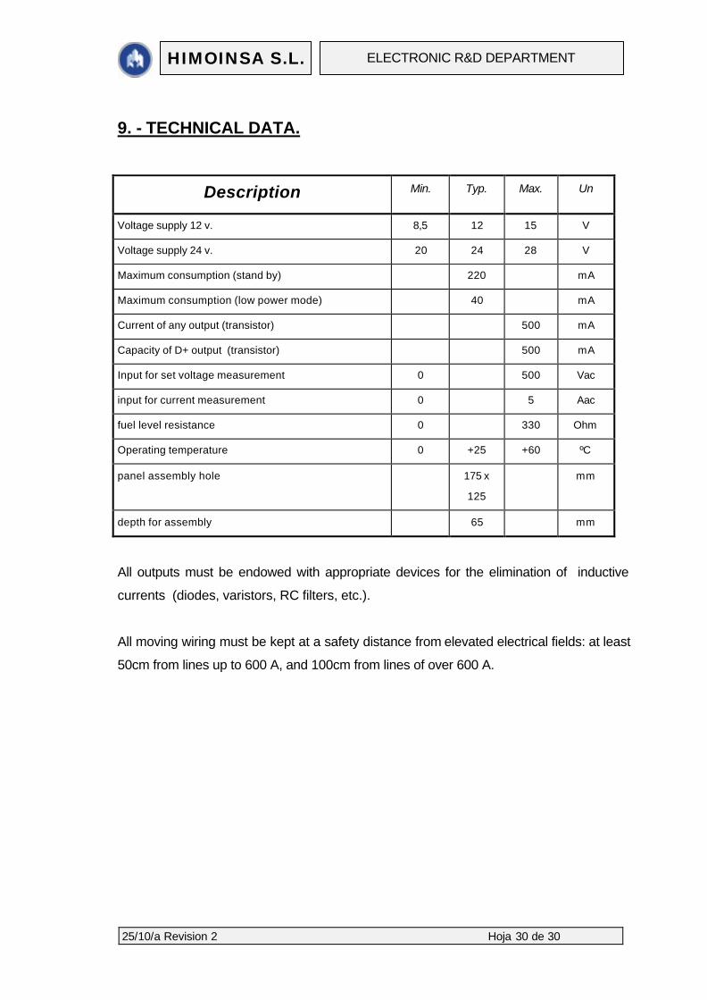
9. - TECHNICAL DATA.
Description Min. Typ. Max. Un
Voltage supply 12 v. 8,5 12 15 V
Voltage supply 24 v. 20 24 28 V
Maximum consumption (stand by) 220 mA
Maximum consumption (low power mode) 40 mA
Current of any output (transistor) 500 mA
Capacity of D+ output (transistor) 500 mA
Input for set voltage measurement 0 500 Vac
input for current measurement 0 5 Aac
fuel level resistance 0 330 Ohm
Operating temperature 0 +25 +60 ºC
panel assembly hole 175 x
125
mm
depth for assembly 65 mm
All outputs must be endowed with appropriate devices for the elimination of inductive
currents (diodes, varistors, RC filters, etc.).
All moving wiring must be kept at a safety distance from elevated electrical fields: at least
50cm from lines up to 600 A, and 100cm from lines of over 600 A.