Embed Size (px)
Citation preview

COPERNICUS MARINE ENVIRONMENT MONITORING SERVICE
CMEMS NRT DU
CMEMS DU Architecture Design Document
Lot 1 – NRT and Forecasts products
Reference: CMEMS-NRT-DU-ADD
Validated by: V. Forneris (CNR)
Document release number: 1.0 draft Date: 26-09-2017
Contributors : G. Barrot (ACRI-ST), M. Barbot (ACRI-ST), G. Corato (adwäisEO), A. Novellino, (ETT), G. Manzella (ETT), G. Vingione (SERCO), V. Forneris (CNR), A. Paciucci(SERCO)

NRT DU Architecture Design DocumentRef : CMEMS-NRTDU-ADD
Date : 26-09-2017
Issue : 1.0 - Draft
CHANGE RECORD
Issue Date § Description of Change Author
1.0
Draft
26-09-2017 all draft release G. Barrot (ACRI-ST), M. Barbot (ACRI-ST), G. Corato (adwäisEO), A. Novellino, (ETT), G. Manzella (ETT), G. Vingione (SERCO), V. Forneris (CNR), A. Paciucci(SERCO)
COPERNICUS MARINE ENVIRONMENT MONITORING SERVICE PAGE 2/ 51

NRT DU Architecture Design DocumentRef : CMEMS-NRTDU-ADD
Date : 26-09-2017
Issue : 1.0 - Draft
TABLE OF CONTENTS
I Introduction.........................................................................................................................................................................12
I.1 Scope...................................................................................................................................................................................12
I.2 Purpose of the Dissemination Unit...................................................................................................................................12
I.3 Summary.............................................................................................................................................................................12
II Overview...............................................................................................................................................................................13
II.1 Architecture design rationale..........................................................................................................................................13
II.2 High level requirements analysis....................................................................................................................................14
II.3 DU high level architecture...............................................................................................................................................15
II.4 Generic sub-DU architecture..........................................................................................................................................16
II.5 Logical architecture of the DU........................................................................................................................................17
II.6 Sizing the CMEMS NRT DU...........................................................................................................................................18
II.7 ADD rules..........................................................................................................................................................................20II.7.1 Naming convention............................................................................................................................20II.7.2 Modelling function............................................................................................................................21
III Modules description........................................................................................................................................................23
III.1 DU NRT front-end..........................................................................................................................................................23III.1.1 Rationale.............................................................................................................................................23III.1.2 Module architecture..........................................................................................................................23III.1.3 Guidelines for implementation.........................................................................................................23III.1.4 Monitoring rules................................................................................................................................23
III.2 Delivery Buffer Server...................................................................................................................................................23III.2.1 Rationale.............................................................................................................................................23III.2.1 DHuS Upgrades to manage new missions.......................................................................................25III.2.2 Module architecture..........................................................................................................................26
III.2.2.1 Heterogeneous Data Ingestion........................................................................................................................26III.2.2.2 PLUG-IN Interface.........................................................................................................................................26III.2.2.3 Readapting the Data Hub System Data Model...............................................................................................27
III.2.3 Guidelines for implementation.........................................................................................................29III.2.4 DHuS extensions implementation for Mercator Ocean DU..........................................................29III.2.5 Download managers (Optional).......................................................................................................29III.2.6 Data Retrieval and DHuS Dataflow Handling upgrades...............................................................29III.2.7 Products Ingestion via Plug-In interface.........................................................................................31
III.2.7.1 DHuS Data Definition via DRB Cortex Ontology..........................................................................................31III.2.8 Monitoring rules................................................................................................................................32
III.3 Data storage.....................................................................................................................................................................32III.3.1 Rationale.............................................................................................................................................33III.3.2 Module architecture..........................................................................................................................33III.3.3 Guidelines for implementation.........................................................................................................33III.3.4 Monitoring rules................................................................................................................................33
III.4 Centralized log server.....................................................................................................................................................33III.4.1 Rationale.............................................................................................................................................33III.4.2 Module architecture..........................................................................................................................34
III.4.2.1 Data gathering <AGE>...................................................................................................................................34III.4.2.2 Data storage (Long-term and Real-time) <DBS>...........................................................................................34III.4.2.3 Data visualization <VIS>................................................................................................................................34III.4.2.4 Data mining <MIN>.......................................................................................................................................35
COPERNICUS MARINE ENVIRONMENT MONITORING SERVICE PAGE 3/ 51

NRT DU Architecture Design DocumentRef : CMEMS-NRTDU-ADD
Date : 26-09-2017
Issue : 1.0 - Draft
III.4.2.5 Alerting <ALT>..............................................................................................................................................35III.4.2.6 SysMA detailed architecture...........................................................................................................................35III.4.2.7 Dashboard Architectural Description..............................................................................................................38
III.5 MFC sub-DU NRT..........................................................................................................................................................38III.5.1 Rationale.............................................................................................................................................38III.5.2 Module architecture..........................................................................................................................38III.5.3 Guidelines for implementation.........................................................................................................38III.5.4 Monitoring rules................................................................................................................................38
III.6 OBS sub-DU NRT...........................................................................................................................................................39III.6.1 Rationale.............................................................................................................................................39III.6.2 Module architecture..........................................................................................................................39III.6.3 Guidelines for implementation.........................................................................................................40III.6.4 Monitoring rules................................................................................................................................40
III.7 INS sub-DU NRT............................................................................................................................................................40III.7.1 Rationale.............................................................................................................................................40III.7.2 Module architecture..........................................................................................................................40III.7.3 Guidelines for implementation.........................................................................................................40III.7.4 Monitoring rules................................................................................................................................40
III.8 Backup System................................................................................................................................................................40III.8.1 Rationale.............................................................................................................................................40III.8.2 Module Architecture.........................................................................................................................42
III.8.2.1 Load Balancer.................................................................................................................................................43III.8.2.2 FTP Server......................................................................................................................................................44III.8.2.3 Data Storage....................................................................................................................................................44III.8.2.4 DU Services....................................................................................................................................................45III.8.2.5 Broker.............................................................................................................................................................46
III.8.3 Guidelines for implementation.........................................................................................................47III.8.3.1 Software configuration....................................................................................................................................48
III.8.4 Monitoring rules................................................................................................................................49
COPERNICUS MARINE ENVIRONMENT MONITORING SERVICE PAGE 4/ 51
NRT DU Architecture Design DocumentRef : CMEMS-NRTDU-ADD
Date : 26-09-2017
Issue : 1.0 - Draft
LIST OF FIGURES
FIGURE 1 – DU NRT ARCHITECTURE...............................................................................................................15
FIGURE 2: COMBINED NRT/MY DU DESCRIPTION..........................................................................................16
FIGURE 3: SUB-DU DESCRIPTION.................................................................................................................... 17
FIGURE 4: LOGICAL ARCHITECTURE OF THE DU..........................................................................................18
FIGURE 5: SIZING OF THE NRT DU................................................................................................................... 20
FIGURE 2 – IDEF0 REPRESENTATION OF ONE PROCESS............................................................................21
FIGURE 3 – EXAMPLE OF IDEF0 GRAPH FROM ESA EODAS ADD................................................................22
FIGURE 8: DATA HUB FUNCTIONAL DECOMPOSITION..................................................................................24
FIGURE 9: DHUS ARCHITECTURAL STRENGTHS...........................................................................................25
FIGURE 10: DATA HUB PLUG-IN CONCEPT.....................................................................................................26
FIGURE 11: DATA MODEL................................................................................................................................. 27
FIGURE 12: STORE SERVICE IMPLEMENTATION...........................................................................................28
FIGURE 13: GENERIC DHUS SYSTEM ARCHITECTURE UPDATE.................................................................28
FIGURE 14: PROPOSED DEPLOYMENT...........................................................................................................28
FIGURE 15: CARONTE APPLICATION DATA FLOW HANDLING......................................................................29
FIGURE 16: AGENT FLOWCHAT........................................................................................................................ 30
FIGURE 17: PULLING COMPONENT.................................................................................................................. 31
FIGURE 18: TRANSFORMATION INTERFACES BASICS..................................................................................31
FIGURE 19: EXAMPLE OF TRANSFORMATION IMPLEMENTATION TREE....................................................32
FIGURE 20: SYSMA FEATURES & FUNCTIONS MAPPING MAP.....................................................................33
FIGURE 21: SYSMA FUNCTIONS & COMPONENTS MAPPING MATRIX.........................................................36
FIGURE 22: SYSMA AGENT PLUGINS...............................................................................................................36
FIGURE 23: DASHBOARD ARCHITECTURE.....................................................................................................38
FIGURE 24 - CMEMS-NRT-OBS/MFC SUB-DU..................................................................................................39
FIGURE 25 – BACKUP SYSTEM – ARCHITECTURE (PHASE 2)......................................................................41
FIGURE 26 – BACKUP SYSTEM – ARCHITECTURE (PHASE 3)......................................................................42
FIGURE 27 – BACKUP SYSTEM – LOGICAL ARCHITECTURE DIAGRAM.......................................................43
FIGURE 28 – BACKUP SYSTEM – BROKER FEEDING THE DATA STORAGE MODULE & THE DU SERVICES.................................................................................................................................................... 46
FIGURE 29 – BACKUP SYSTEM – USER ACCESS...........................................................................................48
FIGURE 30 – BACKUP SYSTEM – NAGIOS EXAMPLE.....................................................................................49
FIGURE 31 – BACKUP SYSTEM – APPLICATIVE LOGS AGGREGATION.......................................................49
FIGURE 32 – BACKUP SYSTEM – KIBANA DASHBOARD EXAMPLE..............................................................50
COPERNICUS MARINE ENVIRONMENT MONITORING SERVICE PAGE 5/ 51

NRT DU Architecture Design DocumentRef : CMEMS-NRTDU-ADD
Date : 26-09-2017
Issue : 1.0 - Draft
GLOSSARY AND ABBREVIATIONS
ACRONYMS
ACRONYMS Wording Meaning
24/7 24 hours a day, 7 days a week Designates a round-the-clock service, including holidays
AAP Annual Activity Plan It describes the activities for the coming year and a preliminary plan for the year after; supports the preparation by Mercator Océan of the Annual Implementation Plan.
AAR Annual Activity Report Detailed report prepared by the Contractor documenting all activities performed by the Contractor during the previous year.
AIP Annual Implementation Plan Detailed plan of the forthcoming annual activity, established every year by Mercator Océan ; responds to the Annual Work Programme ; applied by Con- tractor
AIR Annual Implementation Report Detailed report prepared by Mercator Océan for the European Commission, based on the Annual Activity Reports.
AOR Annual Operation Review Review organized every year to present the status of the service and plan for the coming year
AR Acceptance Review Review ending the development phase of each version. The objective of the AR is to assess successful completion of the development and verification activities and to demonstrate readiness for integration.
AWP Annual Work Programme Overall plan of the forthcoming annual activity, established every year by the European Commission with consultation of the Member States
CCR Contract Closing Review Final Review, required to close the contract
CIS Central Information System The Central Information System is one of the two central elements of the Copernicus Marine Service functional architecture
CMEMS Copernicus Marine environment monitoringService
"Copernicus Marine Service" is the short name of the Copernicus service devoted to the Marine Environment monitoring.
Contractor Contractor This is the entity signing the contract with Mercator Océan for the execution of the corresponding tasks.
CSD CMEMS Central Service Desk The CMEMS Central Service Desk collects, gathers and processes user requests centrally and it relies on a network of local Service Desks.
DR Design Review /Disaster Recovery
Review ending the Design phase. The objective of the DR is to assess the design of the evolutions against the specifications.According to context, it may refers to the Disaster Recovery/backup solution
DU Dissemination Unit A Dissemination Unit is a functional unit in the CMEMS architecture, whose role is to provide access to data
COPERNICUS MARINE ENVIRONMENT MONITORING SERVICE PAGE 6/ 51

NRT DU Architecture Design DocumentRef : CMEMS-NRTDU-ADD
Date : 26-09-2017
Issue : 1.0 - Draft
produced by a Production Unit in a ProductionCentre.
DU Operator DU Operator This is the entity signing the contract with Mercator Océan for the execution of the corresponding tasks.
EIS Entry Into Service Entry Into Service of CMEMS version occurs when CMEMS version is in opera- tions
INS Insitu Thematic Assembly Centre/data The In Situ TAC is one of the 14 Production Centres of the Copernicus Marine Service
ISO International Organisation for Standardiza-tion
www.iso.org - ISO is an independent, non-governmental membership organization developing International Standards.
ITIL Information Technology Infrastructure Library
ITIL (formerly known as the Information Technology Infrastructure Library) is aset of practices for IT service management (ITSM) that focuses on aligning ITservices with the needs of business.
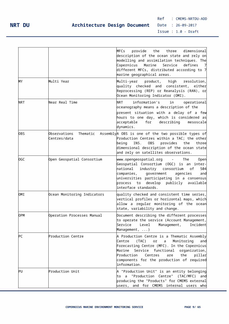
MFC Monitoring and Forecasting Centres A MFC is one of the two possible types of Production Centres; the other being a TAC. MFCs provide the three dimensional description of the ocean state and rely on modelling and assimilation techniques. The Copernicus Marine Service defines 7 different MFCs, distributed according to 7 marine geographical areas.
MY Multi Year Multi-year product, high resolution, quality checked and consistent, either Reprocessing (REP) or Reanalysis (RAN), or Ocean Monitoring Indicator (OMI).
NRT Near Real Time NRT information's in operational oceanography means a description of thepresent situation with a delay of a few hours to one day, which is considered as acceptable for describing mesoscale dynamics.
OBS Observations Thematic Assembly Centres/data
A OBS is one of the two possible types of Production Centres within a TAC; the other being INS. OBS provides the three dimensional description of the ocean state and rely on satellites observations.
OGC Open Geospatial Consortium www.opengeospatial.org - The Open Geospatial Consortium (OGC) is an inter-national industry consortium of 504 companies, government agencies and universities participating in a consensus process to develop publicly available interface standards.
OMI Ocean Monitoring Indicators quality checked and consistent time series, vertical profiles or horizontal maps, which allow a regular monitoring of the ocean state, variability and change.
OPM Operation Processes Manual Document describing the different processes to operate the service (Account Management, Service Level Management, Incident Management, ...)
PC Production Centre A Production Centre is a Thematic Assembly Centre (TAC) or a Monitoring and Forecasting Centre (MFC). In the Copernicus Marine Service functional organization, Production Centres are the pillar components for the production of required information.
PU Production Unit A "Production Unit" is an entity belonging to a "Production Centre" (TAC/MFC) and producing the "Products" for CMEMS external users, and for CMEMS internal users
COPERNICUS MARINE ENVIRONMENT MONITORING SERVICE PAGE 7/ 51

NRT DU Architecture Design DocumentRef : CMEMS-NRTDU-ADD
Date : 26-09-2017
Issue : 1.0 - Draft
who belong to other "Production Centres».
SD Service Desk The CMEMS Service Desk deals with user requests and relies on a network of distributed Service Desks within the CMEMS elements (TACs, MFCs and CIS).
SoW Statement of Work Specifies and describe the Requisites for the call
TAC Thematic Assembly Centre A TAC is one Production Centres.; it delivers in-situ and space data. The Copernicus Marine Service defines 7 different TACs
WMS Web Map Service The OpenGIS® Web Map Service Interface Standard (WMS) provides a simple HTTP interface for requesting geo-registered map images (returned as JPEG, PNG, etc.) that can be layers from multiple servers can be combined.
COPERNICUS MARINE ENVIRONMENT MONITORING SERVICE PAGE 8/ 51
NRT DU Architecture Design DocumentRef : CMEMS-NRTDU-ADD
Date : 26-09-2017
Issue : 1.0 - Draft
DEFINITIONS
Term Definition
Associated products
Associated products that make sense in complement to the standard products.
For example, time invariant products, static files, error bars products are considered as associated products
Dataset
Dataset: A dataset is the aggregation of data observations or analysis and forecast, having the same geospatial structure (or feature type: profiles, pointSeries, trajectories, points, gridSeries, grids ...). It is composed of one or several data files.
The aggregation is done so that the content of the dataset is predictable for the user (list of variables, predefined geographical bounding box) and expandable when the product is updated (time axis).
A dataset can be accessed through an “Access service”.
A dataset is gridded when the data are stored in raster data files (netCDF for instance), each file composing the dataset contains some variables on the same geographical coverage. The difference between two files compos- ing a gridded dataset shall be the time coverage of the variable(s).
If the dataset is not gridded, then it is called ungridded dataset.
Dissemination Interface
Technical mean to access to data through a protocol. Each dataset may be available through one or several dissemination interfaces.
MOTU
Motu is an open-source web server developed by CLS (https://github.com/clstoulouse/motu) allowing the distribution of met/ocean gridded data files through the web. It offers 2 interfaces to the users:
- MOTU-Subsetter (overlay OPENDAP or NCSS)
- MOTU-DGF (Direct Get File)
Subsetter allows user to extract the data of a dataset, with geospatial, temporal and variable criteria. Thus, user downloads only the data of interest.
DGF allows user to extract the data of a dataset with temporal criteria.
A graphic web interface and machine to machine interfaces allow to access data and information on data (metadata). The machine-to-machine interface can be used through a client written in python, freely available (https://github.com/clstoulouse/motu-client-python). Output data files format can be netCDF3 or netCDF4.
An important characteristic of Motu is its robustness: in order to be able to answer many users without crashing, Motu manages its incoming requests in a queue server.
OCEANOTRON
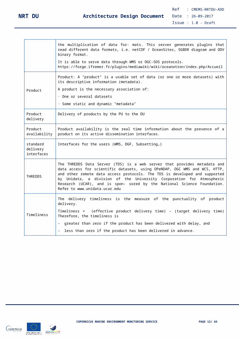
OCEANOTRON is a software created by IFREMER in response to the problem of the multiplication of data for- mats. This server generates plugins that read different data formats, i.e. netCDF / OceanSites, SGBDR diagram and ODV binary format.
It is able to serve data through WMS or OGC-SOS protocols. https://forge.ifremer.fr/plugins/mediawiki/wiki/oceanotron/index.php/Accueil
Product
Product: A "product" is a usable set of data (or one or more datasets) with its descriptive information (metadata).
A product is the necessary association of:
· One or several datasets
· Some static and dynamic "metadata"
Product delivery Delivery of products by the PU to the DU
COPERNICUS MARINE ENVIRONMENT MONITORING SERVICE PAGE 9/ 51

NRT DU Architecture Design DocumentRef : CMEMS-NRTDU-ADD
Date : 26-09-2017
Issue : 1.0 - Draft
Product availability
Product availability is the real time information about the presence of a product on its active dissemination interfaces.
standard delivery interfaces
Interfaces for the users (WMS, DGF, Subsetting…)
THREDDS
The THREDDS Data Server (TDS) is a web server that provides metadata and data access for scientific datasets, using OPeNDAP, OGC WMS and WCS, HTTP, and other remote data access protocols. The TDS is developed and supported by Unidata, a division of the University Corporation for Atmospheric Research (UCAR), and is spon- sored by the National Science Foundation. Refer to www.unidata.ucar.edu
Timeliness
The delivery timeliness is the measure of the punctuality of product delivery.
Timeliness = (effective product delivery time) – (target delivery time) Therefore, the timeliness is
- greater than zero if the product has been delivered with delay, and
- less than zero if the product has been delivered in advance.
COPERNICUS MARINE ENVIRONMENT MONITORING SERVICE PAGE 10/ 51

NRT DU Architecture Design DocumentRef : CMEMS-NRTDU-ADD
Date : 26-09-2017
Issue : 1.0 - Draft
APPLICABLE AND REFERENCE DOCUMENTS
The following documents are applicable: their content is applied as if it were an integral part of this main document.
Ref Title Date / Version
AD 1 CMEMS-TA Copernicus Marine Environment Monitoring – Delegation Agreement - Technical Annex
Sept’17
AD 2 CMEMS-MSP CMEMS Marine Service Portfolio Sept’17
AD 3 CMEMS-URD CMEMS User Requirement Document Sept’17
AD 4 CMEMS-DMP CMEMS Documentation Management Plan Sept’17
AD 5 CMEMS-RTN CMEMS Review Technical Note Sept’17
AD 6 CMEMS-EC-G CMEMS external communication guidelines Sept’17
AD 7 N/A DU Installation and Configuration Technical Documentation
Sept’17
AD 8 CMEMS-CIS-DISS- GW-ADD
Dissemination Gateway Architecture and Design Document
Sept’17
AD 9 CMEMS-CIS-SRD- MOTU
Specification Requirements Document MOTU V3
Sept’17
AD 10 CMEMS-IR Interface requirement for Production Units / Dissemination Units
Sept’17
AD 11 CMEMS-IP CMEMS Integration process Sept’17
AD 12 CMEMS-CMP CMEMS Change Management Plan Sept’17
AD 13 CMEMS-PIT CMEMS Products Information Table Sept’17
AD 14 CMEMS-DU-GUIDE Guidelines for Deliverables Sept’17
AD 15 CMEMS-OPM CMEMS Operation Process Manuel Sept’17
AD 16 85-OD-MF-CMEMS Statement of Work for Dissemination Service
COPERNICUS MARINE ENVIRONMENT MONITORING SERVICE PAGE 11/ 51
NRT DU Architecture Design DocumentRef : CMEMS-NRTDU-ADD
Date : 26-09-2017
Issue : 1.0 - Draft
I Introduction
I.1 Scope The Copernicus Marine Environment Monitoring Service (CMEMS) is the marine application component of the COPERNICUS program. It is a distributed “system of systems“, composed by a Central Information System (CIS), several Production Centres (PC) including Production Units (PU) which can be TAC-type (Thematic Assembly Centres) or MFC-type (Marine Forecast Centres), and a Dissemination Unit (DU).
The objective of this Architecture and Design Document is to describe the logical and physical architecture that fulfills the specification requirements of the Dissemination Units stated in the SOW [DA-1] document.
The ADD identifies the main components of the system and their interfaces, describes the rationale behind the choice of such architecture, and establishes the system architecture guidelines driving the CMEMS DU subsequent development activities.
I.2 Purpose of the Dissemination UnitThe Dissemination Unit (DU) is in charge of the dissemination of the products elaborated by the PCs (TACs and MFCs) making them available to users through several interfaces such as WMS, DGF, Subsetting.
The main targets of the DU operations are:
To set up & maintain infrastructures for integration and operations
To collect the products from Production Units & disseminate them to users
To ensure & monitor the operations related to the collection & dissemination
The Dissemination Unit is also in charge for scaling up and down the resources (i.e. virtual machines and monitoring services).
I.3 Summary This Document applies to LOT 1 Near-Real-Time and Forecasts products. The Consortium has also prepared a proposal for the LOT 2 applying same approaches based on scalability of the system. This document follows this convention:
CMEMS-XXX-DU – applies to any NRT/MY (CMEMS-NRT-DU refers to NRT component only and CMEMS-MY-DU to MY)
XXX-YYY-DU-SD – applies to any (XXX) DU and any (YYY) subDU Service Desk (e.g. NRT-OBS-SD, MY-MFS-SD, etc.)
COPERNICUS MARINE ENVIRONMENT MONITORING SERVICE PAGE 12/ 51

NRT DU Architecture Design DocumentRef : CMEMS-NRTDU-ADD
Date : 26-09-2017
Issue : 1.0 - Draft
II Overview
II.1 Architecture design rationaleThe main target of the DU design is to propose a technical solution that is robust, modular and easily deployable on a cloud infrastructure.
Robust: modules shall be based on standard widely used libraries. If needed, modifications of these libraries shall be made using state-of-the-art coding rules. Robust also means that the system is not completely blocked when one element fails. For example, the design shall be made such as the delivery to users still continues even if the NRT data flow is broken: archive shall stay accessible. Data buffering shall be used where needed and as much as possible, return to operation shall be as simple as possible: when a component is no more available, the design shall be made that the upstream component should be as less as possible affected. Components shall also be deployed on several physical systems in clusters.
Modular: architecture shall apply the following rule: “one object = one function”. Avoid side effects between modules. Modules shall be connected via well-defined interfaces.
Easily deployable: architecture shall avoid using functionalities specific to any physical entity.
Having these simple rules in mind, the DU has been first of all decomposed in very high-level modules.
The first main update since the actual DU system is to provide a single point of access (URL) for all data (NRT and/or MY). This will be performed by a load-balancer/traffic-dispatcher system used as unique frontend URL.
Behind this frontend, data is logically divided by typology into three main sub-DUs: Observation data (OBS), Marine Forecast data (MFC) and in-situ data (INS), each operated by a specific Partner who’s particularly expert in that field.
Each sub-DU will be composed of two or more machines (planned to be VMs in the frame of the MO infrastructure) connected to a common storage system/space, which assures the consistency of the interfaces without impacting on data volume (no duplication – except if automatically provided by the data security layer of the MO infrastructure).
Note: for HA reason, if allowed by MO’s cloud System, the VMs will be distributed on different physical hosts.
Splitting the DU into sub-DUs (and more VMs per sub-DU) will improve:
performances - improved further in case enough physic hosts thanks to more independent CPUs and disks used
robustness - more components can crash without impacting the access to data
flexibility – changes on a sub-DU won’t impact others interfaces; VMs can be deployed/un-deployed depending on needs and resources available; new interfaces can be set up on same data without impacting operative tasks
tuning of interfaces - due to the different nature of the data, DU operator will apply specific best practise and even different SW/approaches (e.g. INS data won’t use THREDDS data server catalogue).
In addition, the scalability of the system will be granted by the MO cloud environment.
Concerning the interface DU-PU for gathering and delivering products/files, the DU operator will set up a Delivery Buffer Server (DBS), where PUs will upload files. As this is requested by the “INTERFACE REQUIREMENTS FOR PRODUCTION UNITS/ DISSEMINATION UNITS” (IR) document, a continuously running process will:
analyse the Delivery Note text sent by PUs
COPERNICUS MARINE ENVIRONMENT MONITORING SERVICE PAGE 13/ 51

NRT DU Architecture Design DocumentRef : CMEMS-NRTDU-ADD
Date : 26-09-2017
Issue : 1.0 - Draft
identify files by filenames & Delivery Note inputs
perform quality checks, such as data integrity, formats, etc., as foreseen by IR
manage files, delivering in proper storages, deleting superseded files, etc.
raise alerts in case of files rejection/problems.
measure the delivery time (against the expected one)
The DBS will also collect logs from various servers/services, providing a single-access log-server, and graphical dashboards will be defined to provide graphs on:
data delivery statistics
data download statistics
service’s interfaces availability statistics
IMPORTANT
Due to the lack of information about the Cloud Environment Mercator Océan will provide, the Architecture Design Document describes generic solutions applicable to any system. The DU operator reserves the right and opportunity to re-analyse the solutions proposed based on MO inputs in order to improve the general system design (e.g. type and size of the overall resources at disposition, elasticity functionalities, advanced storage features such as auto-tiering, data duplication, etc.)
II.2 High level requirements analysis[REQ-NRT-DU-001]:
infrastructure = cloud, all the functionalities could be replicated in the back-up outside the CMEMS cloud, with data accessible in cold archives (tapes) instead of disks in the CMEMS cloud, in case of failures of the cloud
Software= CFIs will be implemented in all sub-DUS, with an overall orchestrator in the DU front-end. Open source will be considered whenever applicable.
Security: All security aspects are addressed into the SMP – Security Management Plan
Users’ Access security is provided by CIS because the web interface (normally in a DMZ anywhere) –services access to data base and data processing by service accounts and security is managed by DU active directories services, encryption is not considered
[REQ-NRT-DU-002]: configuration with a server Haproxy, many FTP servers, many geoservers (WMS) and web servers (TOMCAT) either distinct (for each DU…) or communalized, which will work on VMs
[REQ-NRT-DU-003]: as further broken-down and detailed in the ADD.
[REQ-NRT-DU-004]: best is to have many NFS servers connected to same data stores for sharing fluxes & load balances
[REQ-NRT-DU-005]: as further broken-down and detailed in the ADD
[REQ-NRT-DU-007]: with Haproxy for sharing the load of different servers that provide the same services .
[REQ-NRT-DU-009]: opendap, haproxy, geoservers, etc.
COPERNICUS MARINE ENVIRONMENT MONITORING SERVICE PAGE 14/ 51

NRT DU Architecture Design DocumentRef : CMEMS-NRTDU-ADD
Date : 26-09-2017
Issue : 1.0 - Draft
[REQ-NRT-DU-017]: a web portal using tomcat or apache technologies provides an access via haproxy to contact subservices and these services access data storage repositories by one or more NFS servers.
II.3 DU high level architectureThe following figure presents the high level definition of the proposed DU architecture.
Figure 1 – DU NRT architecture
The Dissemination Unit is structured around sub-DUs which are dedicated to the distribution of INS (in-situ), OBS (satellite data) and MFC (forecasts) data. These sub-DUs are alimented by a unique component and they are also visible for the users via a unique component.
The Dissemination Unit is therefore mainly composed of:
a Delivery Buffer module which is the interface between the PUs and the sub-dissemination units (INS, OBD, MFC).
storage components, one per data type (INS, OBS, MFC).
sub-DUs components, one per data type (INS, OBS, MFC).
a Dissemination System front-end which is the interface between the sub-DUs and the users.
a Backup System, which plays also the role of business continuity component.
COPERNICUS MARINE ENVIRONMENT MONITORING SERVICE PAGE 15/ 51
NRT DU Architecture Design DocumentRef : CMEMS-NRTDU-ADD
Date : 26-09-2017
Issue : 1.0 - Draft
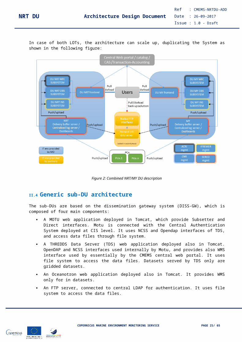
In case of both LOTs, the architecture can scale up, duplicating the System as shown in the following figure:
Figure 2: Combined NRT/MY DU description
II.4 Generic sub-DU architectureThe sub-DUs are based on the dissemination gateway system (DISS-GW), which is composed of four main components:
A MOTU web application deployed in Tomcat, which provide Subsetter and Direct interfaces. Motu is connected with the Central Authentication System deployed at CIS level. It uses NCSS and Opendap interfaces of TDS, and access data files through file system.
A THREDDS Data Server (TDS) web application deployed also in Tomcat. OpenDAP and NCSS interfaces used internally by Motu, and provides also WMS interface used by essentially by the CMEMS central web portal. It uses file system to access the data files. Datasets served by TDS only are gridded datasets.
An Oceanotron web application deployed also in Tomcat. It provides WMS only for in datasets.
An FTP server, connected to central LDAP for authentication. It uses file system to access the data files.
The applications using HTTP protocol (all applications except FTP server) are deployed behind a frontal Apache HTTPd server which manages HTTP incoming requests. It also serves static files (html, css, js, and media files like images) and result data files.
COPERNICUS MARINE ENVIRONMENT MONITORING SERVICE PAGE 16/ 51

NRT DU Architecture Design DocumentRef : CMEMS-NRTDU-ADD
Date : 26-09-2017
Issue : 1.0 - Draft
Figure 3: Sub-DU description
The DISS-GW provides 4 main interfaces:
Subsetter interface, allowing the user to access datasets, and extract the needed data (variable, geospatial and temporal extraction facilities). This interface covers in term of functionalities the Web Coverage Service of OGC.
Direct Get File interface, allowing the user to access datasets, and choose the time steps in the temporal aggregation.
FTP, allowing the user to access files of datasets.
Web Map Service, which allow to implement the viewing service. The DISS-GW is the server part of the viewing service. Client part is implemented in the web portal. WMS for gridded data is implemented by TDS, WMS for in-situ data is provided by Oceanotron.
The DISS-GW is adapted to the data type (OBS, INS, MFC).
II.5 Logical architecture of the DUIn case of deployment of such a system in a Cloud: a DMZ will host all services that are readily accessible from internet, i.e. the ftp servers and the DU front-end (services Haproxy) if the web portal is outside the cloud –if the CIS in the same cloud, one can imagine that the CIS web portal and the DU front-end will be in the same DMZ.
COPERNICUS MARINE ENVIRONMENT MONITORING SERVICE PAGE 17/ 51

NRT DU Architecture Design DocumentRef : CMEMS-NRTDU-ADD
Date : 26-09-2017
Issue : 1.0 - Draft
Figure 4: Logical architecture of the DU
Most probably the data will be distributed by the Delivery Buffer Server to the Insitu-OBS-MFC repositories via NFS servers with right security devices depending on the storage devices.
With regards to the link between the Cloud and the back-up by internet, there are two solutions for the backups: - the distribution of data to the back-up and Log-shipping replication, or - a replication disks-to-tapes from the cloud to the back-up (e.g. protocols ASL or Flexsync) if we have a VPN LAN to LAN.
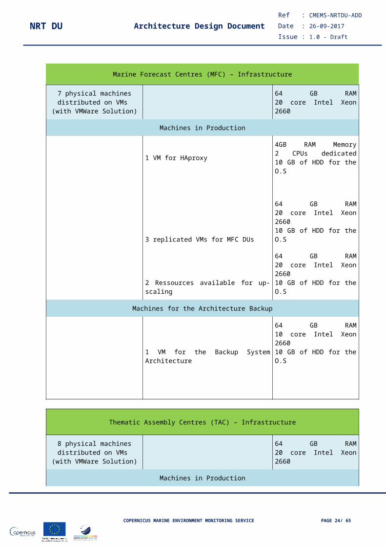
II.6 Sizing the CMEMS NRT DU The sizing is based on two separate Lots for NRT & MY. In case they are grouped, the resources for upscaling would be shared. The sizing is done for matching performances defined in the SOW.
Marine Forecast Centres (MFC) – Infrastructure
7 physical machines distributed on VMs
(with VMWare Solution) 64 GB RAM20 core Intel Xeon 2660
Machines in Production
COPERNICUS MARINE ENVIRONMENT MONITORING SERVICE PAGE 18/ 51

NRT DU Architecture Design DocumentRef : CMEMS-NRTDU-ADD
Date : 26-09-2017
Issue : 1.0 - Draft
1 VM for HAproxy4GB RAM Memory2 CPUs dedicated10 GB of HDD for the O.S
3 replicated VMs for MFC DUs
64 GB RAM20 core Intel Xeon 266010 GB of HDD for the O.S
2 Ressources available for up-scaling
64 GB RAM20 core Intel Xeon 266010 GB of HDD for the O.S
Machines for the Architecture Backup
1 VM for the Backup System Architecture
64 GB RAM10 core Intel Xeon 266010 GB of HDD for the O.S
Thematic Assembly Centres (TAC) – Infrastructure
8 physical machines distributed on VMs
(with VMWare Solution) 64 GB RAM20 core Intel Xeon 2660
Machines in Production
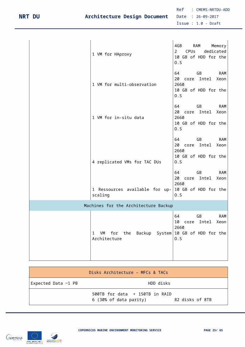
1 VM for HAproxy4GB RAM Memory2 CPUs dedicated10 GB of HDD for the O.S
1 VM for multi-observation64 GB RAM20 core Intel Xeon 266010 GB of HDD for the O.S
1 VM for in-situ data64 GB RAM20 core Intel Xeon 266010 GB of HDD for the O.S
4 replicated VMs for TAC DUs
64 GB RAM20 core Intel Xeon 266010 GB of HDD for the O.S
1 Ressources available for up-scaling
64 GB RAM20 core Intel Xeon 266010 GB of HDD for the O.S
COPERNICUS MARINE ENVIRONMENT MONITORING SERVICE PAGE 19/ 51

NRT DU Architecture Design DocumentRef : CMEMS-NRTDU-ADD
Date : 26-09-2017
Issue : 1.0 - Draft
Machines for the Architecture Backup
1 VM for the Backup System Architecture
64 GB RAM10 core Intel Xeon 266010 GB of HDD for the O.S
Disks Architecture – MFCs & TACs
Expected Data ~1 PB HDD disks
500TB for data + 150TB in RAID 6 (30% of data parity) 82 disks of 8TB
500TB for data Backup 63 disks of 8TB
NFS Servers Requirements
1 or 2 NFS Server(s) for each Dissemination Unit
1 dedicated NFS Server for the Backup System
Figure 5: Sizing of the NRT DU
For having a sustainable and reliable service, we should consider adding NFS Servers in charge of disseminating data over HDDs.
We propose to allocate 2 NFS Servers for each DU Type and 1 dedicated NFS Server for the Backup System.
As NFS Servers are independent for each DU, this configuration will provide a guaranteed access to the data storage.
II.7 ADD rules
II.7.1 Naming conventionThis chapter provides the rules applied in this document and the project to identify the various objects involved in the Dissemination Unit system.
These objects will be named (to be consolidated):
<System>_<Sub_System>_<Type>_<Mnemonic>
where:
- System: acronym of the system (here DU)
- Sub-system: acronym of the sub-system
o GEN for the generic functionso BS for the Backup Systemo DB for the Delivery Buffer
COPERNICUS MARINE ENVIRONMENT MONITORING SERVICE PAGE 20/ 51
NRT DU Architecture Design DocumentRef : CMEMS-NRTDU-ADD
Date : 26-09-2017
Issue : 1.0 - Draft
o FE for the Front-Endo MFC for the MFC sub-DUo OBS for the OBS sub-DUo INS for the INS sub-DUo etc
- Type: class of the object
o M for the moduleso C for the componentso I for the interfaceso etc
- Mnemonic: short name of the object in modified Camel Case. Each word starts with a capital letter. Underscores as word separators.
Examples of valid object names:- DU_BS_I_Data_Broker_Configuration
- DU_BS_C_FTP_Server
- DU_DB_C_Data_Push_To_SubDU
<< To be completed for the DU components >>
II.7.2 Modelling functionThe modeling methodology used in this ADD is based on IDEF0 standards. This is a quite simple approach to describe processes. Each component/module/function/process can be represented as a “box” such as:
A0
processinput
control
mechanism
output
Figure 6 – IDEF0 representation of one process
IDEF0 standards have been used by ACRI-ST in several projects, e.g. the ESA EODAS service ADD is based on IDEF0 methodology.
COPERNICUS MARINE ENVIRONMENT MONITORING SERVICE PAGE 21/ 51

NRT DU Architecture Design DocumentRef : CMEMS-NRTDU-ADD
Date : 26-09-2017
Issue : 1.0 - Draft
Figure 7 – example of IDEF0 graph from ESA EODAS ADD
<< To be completed for the DU components >>
COPERNICUS MARINE ENVIRONMENT MONITORING SERVICE PAGE 22/ 51

NRT DU Architecture Design DocumentRef : CMEMS-NRTDU-ADD
Date : 26-09-2017
Issue : 1.0 - Draft
III Modules description
This chapter intends to present an overview of the DU system by describing each of its modules. Note that the description is common to the NRT and MY modes.
III.1 DU NRT front-end
III.1.1 RationaleWe provide fine-grained APIs, which means that clients need to interact with multiple services. The number of service instances and their locations (host+port) may changes dynamically, also partitioning into services can change over time and should be hidden from clients.
III.1.2 Module architectureImplement an API gateway that is the single entry point for all clients. The API gateway handles requests in one of two ways. Some requests are simply proxied/routed to the appropriate service, while others by fanning out to multiple services.
III.1.3 Guidelines for implementationThe initial implementation uses an HAproxy instance as API gateway, using simple rules based on the URL requested by the users for routing. A circuit breaker design pattern shall be put in place to cope with failures on the backing services. Authentication is delegated to the single services and it will not be handled by the API Gateway. Load balancing shall be ensured by the gateway in case a service has multiple replicas.
III.1.4 Monitoring rulesThere are three categories of metrics for the API Gateway:
Frontend metrics such as client connections and requests Backend metrics such as availability and health of backend servers Health metrics that reflect the state of the HAProxy setup
Those metrics shall be collected and parsed by a centralized ELK stack described in the following paragraphs.
III.2 Delivery Buffer Server
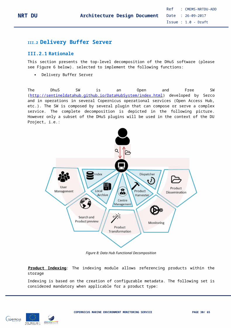
III.2.1 RationaleThis section presents the top-level decomposition of the DHuS software (please see Figure 6 below). selected to implement the following functions:
Delivery Buffer Server
The DhuS SW is an Open and Free SW (http://sentineldatahub.github.io/DataHubSystem/index.html) developed by Serco and in operations in several Copernicus operational services (Open Access Hub, etc.). The SW is composed by several plugin that can compose or serve a complex service. The complete decomposition is depicted in the following picture. However only a subset of the DHuS plugins will be used in the context of the DU Project, i.e.:
COPERNICUS MARINE ENVIRONMENT MONITORING SERVICE PAGE 23/ 51
NRT DU Architecture Design DocumentRef : CMEMS-NRTDU-ADD
Date : 26-09-2017
Issue : 1.0 - Draft
Figure 8: Data Hub Functional Decomposition
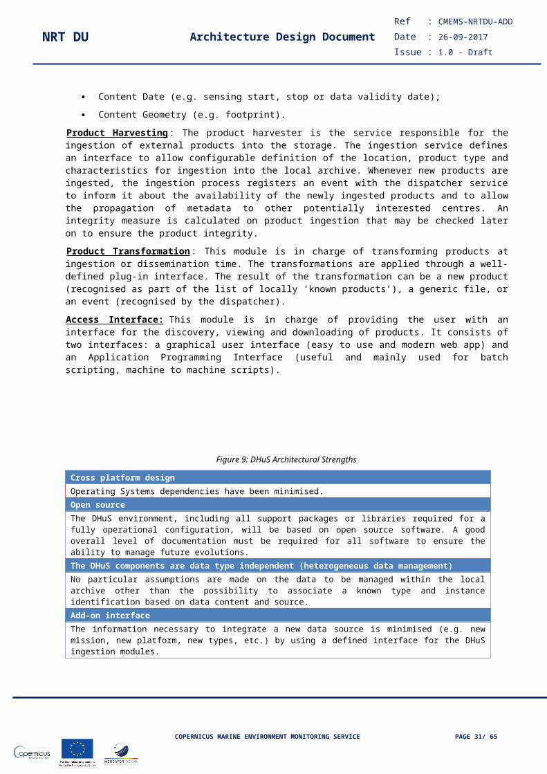
UUProduct Indexing : The indexing module allows referencing products within the storage
Indexing is based on the creation of configurable metadata. The following set is considered mandatory when applicable for a product type:
Content Date (e.g. sensing start, stop or data validity date);
Content Geometry (e.g. footprint).
UUProduct HarvestingUU: The product harvester is the service responsible for the ingestion of external products into the storage. The ingestion service defines an interface to allow configurable definition of the location, product type and characteristics for ingestion into the local archive. Whenever new products are ingested, the ingestion process registers an event with the dispatcher service to inform it about the availability of the newly ingested products and to allow the propagation of metadata to other potentially interested centres. An integrity measure is calculated on product ingestion that may be checked later on to ensure the product integrity.
UUProduct TransformationUU: This module is in charge of transforming products at ingestion or dissemination time. The transformations are applied through a well-defined plug-in interface. The result of the transformation can be a new product (recognised as part of the list of locally ‘known products’), a generic file, or an event (recognised by the dispatcher).
AAccess Interface: UThis module is in charge of providing the user with an interface for the discovery, viewing and downloading of products. It consists of two interfaces: a graphical user interface (easy to use and modern web app) and an Application Programming Interface (useful and mainly used for batch scripting, machine to machine scripts).
COPERNICUS MARINE ENVIRONMENT MONITORING SERVICE PAGE 24/ 51
NRT DU Architecture Design DocumentRef : CMEMS-NRTDU-ADD
Date : 26-09-2017
Issue : 1.0 - Draft
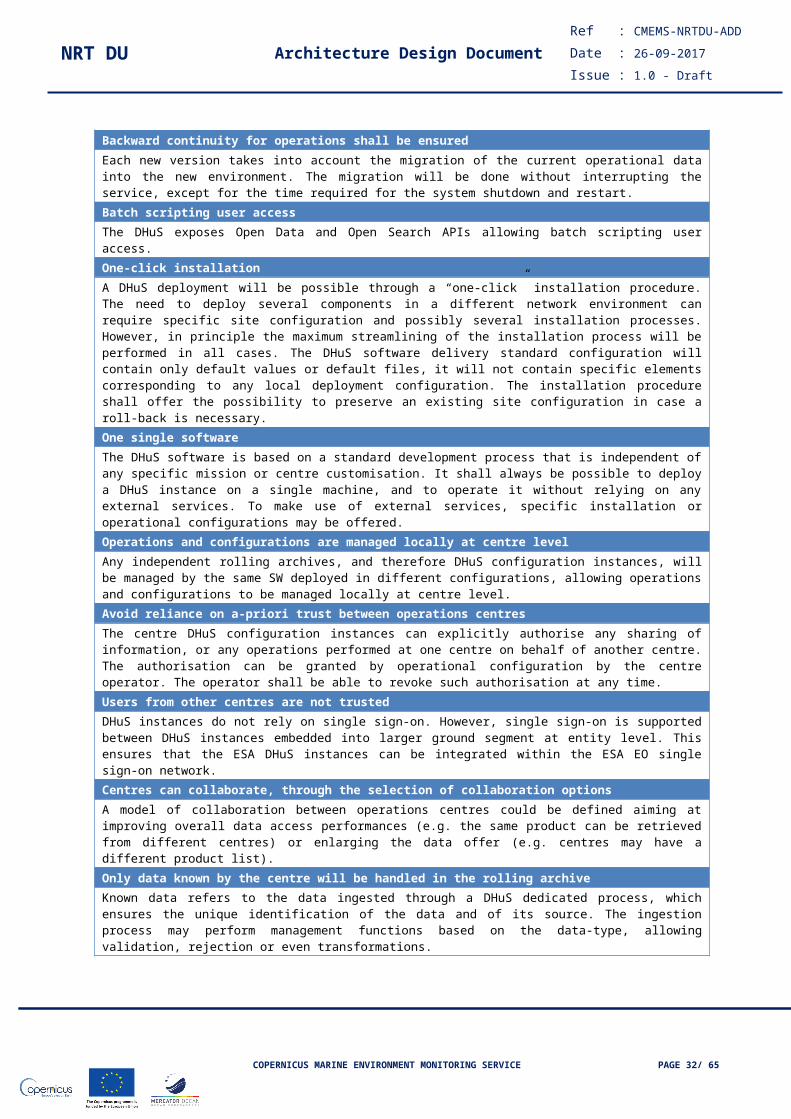
Figure 9: DHuS Architectural Strengths
Cross platform designOperating Systems dependencies have been minimised.Open source The DHuS environment, including all support packages or libraries required for a fully operational configuration, will be based on open source software. A good overall level of documentation must be required for all software to ensure the ability to manage future evolutions.The DHuS components are data type independent (heterogeneous data management)No particular assumptions are made on the data to be managed within the local archive other than the possibility to associate a known type and instance identification based on data content and source.Add-on interfaceThe information necessary to integrate a new data source is minimised (e.g. new mission, new platform, new types, etc.) by using a defined interface for the DHuS ingestion modules.Backward continuity for operations shall be ensuredEach new version takes into account the migration of the current operational data into the new environment. The migration will be done without interrupting the service, except for the time required for the system shutdown and restart.Batch scripting user accessThe DHuS exposes Open Data and Open Search APIs allowing batch scripting user access.One-click installationA DHuS deployment will be possible through a “one-click” installation procedure. The need to deploy several components in a different network environment can require specific site configuration and possibly several installation processes. However, in principle the maximum streamlining of the installation process will be performed in all cases. The DHuS software delivery standard configuration will contain only default values or default files, it will not contain specific elements corresponding to any local deployment configuration. The installation procedure shall offer the possibility to preserve an existing site configuration in case a roll-back is necessary.One single software The DHuS software is based on a standard development process that is independent of any specific mission or centre customisation. It shall always be possible to deploy a DHuS instance on a single machine, and to operate it without relying on any external services. To make use of external services, specific installation or operational configurations may be offered.Operations and configurations are managed locally at centre levelAny independent rolling archives, and therefore DHuS configuration instances, will be managed by the same SW deployed in different configurations, allowing operations and configurations to be managed locally at centre level.Avoid reliance on a-priori trust between operations centresThe centre DHuS configuration instances can explicitly authorise any sharing of information, or any operations performed at one centre on behalf of another centre. The authorisation can be granted by operational configuration by the centre operator. The operator shall be able to revoke such authorisation at any time.Users from other centres are not trusted DHuS instances do not rely on single sign-on. However, single sign-on is supported between DHuS instances embedded into larger ground segment at entity level. This ensures that the ESA DHuS instances can be integrated within the ESA EO single sign-on network.Centres can collaborate, through the selection of collaboration optionsA model of collaboration between operations centres could be defined aiming at improving overall data access performances (e.g. the same product can be retrieved from different centres) or enlarging the data offer (e.g. centres may have a different product list). Only data known by the centre will be handled in the rolling archiveKnown data refers to the data ingested through a DHuS dedicated process, which ensures the unique identification of the data and of its source. The ingestion process may perform management functions based on the data-type, allowing validation, rejection or even transformations.
COPERNICUS MARINE ENVIRONMENT MONITORING SERVICE PAGE 25/ 51

NRT DU Architecture Design DocumentRef : CMEMS-NRTDU-ADD
Date : 26-09-2017
Issue : 1.0 - Draft
III.2.1 DHuS Upgrades to manage new missionsThe impact of implementing the CMEMS DU Scenarios in the DHuS architecture implies per se:
Definition and implementation of the CMEMS products ingestion chain;
Definition and implementation of the dataflow integration, to gather the products from the respective sources, and the internal dataflow for the rolling archive management;
Adaptation of the DHuS internal data model for the new mission’s products, especially as regards:
o Recognition;
o Ingestion;
o Indexing;
o Cataloguing;
o Archiving.
The best solution for successfully managing the integration of CMEMS prodcuts is the reuse and adaptation of the DHuS native functions.
The DHuS is designed to minimise the dependency on type and format of the input data. However, due to the heterogeneity of the CMEMS data formats, dedicated ingestion plug-ins will be delivered.
III.2.2 Module architectureIII.2.2.1 Heterogeneous Data Ingestion A remarkable aspect of the DHuS is its capability to handle virtually any data type, even if not common in EO products dissemination systems. This capability allows the distribution of auxiliary files or other documents, and guarantees that the CMEMS products, which may have various content types or construction rules will be supported. The DHuS makes use of the DRB API that acts as an abstract layer that rids the system of any concept tied to the EO domain, e.g. the DHuS has no specific knowledge about satellites, sensors or acquisition modes, and yet it is capable of handling accurately this kind of information. The DRB API has demonstrated this abstraction capability for many products, including the Derby Application® than can browse all the Sentinels product types, as well as other product types, independent from the EO domain (see http://sentineldatahub.github.io/DataHubSystem/multi-mission-access.html ).
III.2.2.2 PLUG-IN InterfaceA powerful capability of the DHuS SW is to allow the upgrade of the core and built-in features by third-parties via plug-ins. This approach is proposed for the development of the new mission add-on.
COPERNICUS MARINE ENVIRONMENT MONITORING SERVICE PAGE 26/ 51

NRT DU Architecture Design DocumentRef : CMEMS-NRTDU-ADD
Date : 26-09-2017
Issue : 1.0 - Draft
Figure 10: Data Hub Plug-in concept At this level, the plug-in would consist in a sub-directory of a DHuS installation. The sub-directory would be scanned at start-up and the Ontologies and accompanying resources loaded. Then the plug-in resources would be considered and executed as if they were built-in resources.
This level allows the installation of new definitions provided independently from the core or main installation.
III.2.2.3 Readapting the Data Hub System Data ModelTo manage the heterogeneous mission data ingestion, a generic Data Model is used into the DHus. The main principles for the DHuS data model are:
Independent Domain Object Interface
Independent and Rationalised Domain Logic Interface
User Access Interfaces (i.e. APIs)
In the frame of Mercator Ocean, the proper Object Interface and Domain Logic Interface will be configured based on the results of the overall design phase.
Independent Domain Object Interfaces The current software baseline includes functional implementations of objects such as Products or Collections, but may suffer from the location of their definition or from their nature. For example, the Products are handled by a concrete class defined under the database package. It is a natural starting location because, up to now, the Products had to be stored by representative in a relational database. Today there is the need to support NoSQL databases or any store of any nature, local or remote, storing metadata only or actual data too, as for MongoDB+GridFS therefore the concrete class becomes a limitation.
The Mercator Ocean Products definition will be designed as a bare interface, independent from any implementation and in particular from an SQL relational database system.
Independent and Rationalized Domain Logic InterfacesRecent SW researches show that the independence of domain objects could also be completed by independent domain logic via Service interfaces. In certain ways they already exist as the Data Access Object (DAO) or the DataStore objects, but still depend on the general concept that a DHuS instance must have separate storage means for metadata (in a database system via DAOs) and for actual data (in a file system or equivalent via the DataStore interface). The case of “MongoDB+GridFS” that can handle both metadata and data, suggests a higher level of abstraction bringing very interesting deployment scenarios.
COPERNICUS MARINE ENVIRONMENT MONITORING SERVICE PAGE 27/ 51

NRT DU Architecture Design DocumentRef : CMEMS-NRTDU-ADD
Date : 26-09-2017
Issue : 1.0 - Draft
The following dedicated implementation will be adopted for the DU service needs:
The Data Access Object (DAO) will become a pure interface, independent from any storage system and should handle both product metadata and data. It is up to the implementations to decide if the data or metadata should be separated, or even not supported. As a reminder, the Data Access Object (DAO) is a design pattern that defines an interface for CRUD (Create, Read, Update and Delete) operations for each domain object e.g. ProductDao, CollectionDao, etc;
A Storage service interface will gradually replace the DataStore interface and will represent a DAO factory.
Figure 11: Data Model
From the above principles, the following generic architecture will be applied in the Mercator Ocean project.
The diagram in Figure 11 provides a static view of the model including only pure and independent interfaces where the Collection and Product are handled (CRUD operations) by the DAOs instantiated by a Store service. Then a Synchronizer interface can handle the content synchronization between multiple stores, not only for Products, but ideally for any domain object supported by the Store.
This architecture enables a large variety of implementations and deployments according to the operation context and needs. Based on the replication of the current operational scenario, it is possible to figure out the immediate benefits of the architecture.
Figure 12: Store service implementation
The above diagram depicts three implementations of the Store service for wrapping a file system (FsStore), a relational database (HibernateStore) and a Solr index (SolrStore), and a DefaultSynchronizer, which all should suffice to reproduce the current DU operational behaviour.
Figure 13: Generic DHuS System Architecture Update
COPERNICUS MARINE ENVIRONMENT MONITORING SERVICE PAGE 28/ 51

NRT DU Architecture Design DocumentRef : CMEMS-NRTDU-ADD
Date : 26-09-2017
Issue : 1.0 - Draft
Instantiated as in the above diagram, it is possible to figure out that a single Synchronizer configured in “one way” mode is capable of handling the dedicated DU ingestion process, reading the products from the “Input Folder” which is an instance of FsStore, and putting them in successive store disregarding their implementation. In this example, the first put will occur in an “Incoming Folder” which is also an implementation of the FsStore and then in the HibernateStore and the SolrStore. Automated migrations are also possible between different types or versions of Stores. For example, an old Solr index can be cleaned or regenerated by setting up a one-way synchronization between two SolrStore instances, maybe with two different software versions.
The deployment that will be implemented in the frame of Mercator Ocean DU service is depicted in the figure below.
Figure TBDFigure 14: Proposed deployment
The objective is to distribute the load between the VMs.
III.2.3 Guidelines for implementation
III.2.4 DHuS extensions implementation for Mercator Ocean DUIn addition to the DHuS native functions re-adaptation described in the above sections the following new implementations have to be done:
Implementation of new data retrieval modules;
DHuS Dataflow Handling upgrades to manage the new missions;
New Data Ingestion Plug-in;
Detailed implementation is described in the following sections.
III.2.5 Download managers (Optional)Objective of the Consortium is to build an Enterprise Service Bus for designing and implementing communication between the DHuS software and the EO data sources. The main duties of an ESB are:
Monitor and control routing of message exchange between services;
Resolve contention between communicating service components;
Control deployment and versioning of services;
Marshal use of redundant services;
Cater for commodity services like event handling, data transformation and mapping, message and event queuing and sequencing, security or exception handling, protocol conversion and enforcing proper quality of communication service.
This architecture looks like the best fit for the Mercator Ocean DU project where the interface between the DHuS and the EO Data Sources has to be established (most of the systems are geographically distributed, are developed by different contractors and use different interfaces and technologies). Typical scenarios could include:
Access to products from a local folder;
Access to remote products.
COPERNICUS MARINE ENVIRONMENT MONITORING SERVICE PAGE 29/ 51
NRT DU Architecture Design DocumentRef : CMEMS-NRTDU-ADD
Date : 26-09-2017
Issue : 1.0 - Draft
III.2.6 Data Retrieval and DHuS Dataflow Handling upgradesCaronte module is Serco in-house software, currently used in the Copernicus Open Access Service operations, designed to distribute and prioritize, with dedicated queues, the different input products into the ‘incoming’ folders of the Data Hub System. The prioritization and dissemination is realized by a rule-based engine. Once products are available on the local folder of the DU (i.e. after the retrieval from the source or push by the source, e.g. the PU) they need to be verified and passed to the ingestion module. This step is fundamental for demonstrating the operability of the system. Caronte’s primary need is to move products from the download folder into the DHuS scanners inboxes, but only when each single product is fully downloaded, by checking its integrity according to what isdeclared in the product manifest. Then, to ensure that products could be moved to different inboxes or side-lined for future ingestion by DHuS, Caronte will be enriched by a Mercator Ocean-dedicated “Filter” functionality.
Figure TBDFigure 15: Caronte Application Data Flow Handling
In the context of the Mercator Ocean project, the Consortium proposes to parallelise the Caronte tasks by distributing load on most of the platform resources, to improve its scalability in view of the new missions. This is accomplished by using some atomic components that are regulated by a centralized configuration. The main Caronte tasks are:
Check product integrity before processing it;
Filter destination of products according to name-based criteria;
Compress input products or skip product according to filter applied;
Move ZIP file into DHuS inboxes according to filter applied;
Save a backup copy of the input data.
When products are finalized by the download manager, they are pushed in the queue and managed. It is worth mentioning that Caronte implements two methods for the Queue object: Push and Pull product. “Collector agents” check the product integrity to verify if it was downloaded properly and, in case it is not, the product can be deleted and resubmitted to the download manager for a new download request. The consumer of the product queue is “Caronte Agent”. To achieve scalability and to allow using all available resources, every node of the platform will run an Agent instance every minute. The flowchart of the agent is depicted in the Figure 16.
Figure 16: Agent Flowchat
COPERNICUS MARINE ENVIRONMENT MONITORING SERVICE PAGE 30/ 51
NRT DU Architecture Design DocumentRef : CMEMS-NRTDU-ADD
Date : 26-09-2017
Issue : 1.0 - Draft
The last component is the atomic part that performs most of the Caronte tasks for a single product, called “Product Zipper”. This component is pulling out one product from the queue and performing the remaining of the tasks, in accordance with the flow diagram in Figure 17.
Figure 17: Pulling component
III.2.7 Products Ingestion via Plug-In interfaceA Product Ingestion is a specific DHuS Transformation dedicated to the EO data management. It includes:
Metadata Extraction;
Indexing attributes generation;
Preview/Thumbnail preparation.
The Data Transformation is a critical service dedicated to apply transformations, usually extractions, and to store the results in the DHuS Databases. Upon reception of a product, the Data Transformation service resolves the data type according the current Data Definition (through DRB API and its Cortex extension) and fetches the associated transformation specifications. These transformations are then applied only if their definitions are compatible with a fast processing and with storage in a Database. For Mercator Ocean DU service, the criteria are still to be defined but it could only consist in an “automatic” flag in the transformation definition. A smarted mechanism could be based on the target MIME types and expected result size computation but the reliability of such theory should be confirmed during the project.
The interest of this service is to have a common processing interface that will extract the metadata as XML documents, compute the previews and thumbnails as PNG/GeoTIFF images, search attributes as XML documents, or any processing still not envisaged at the time of writing without recompiling the server.
III.2.7.1 DHuS Data Definition via DRB Cortex Ontology The data definition for the DHuS architecture is a critical component and relies on the DRB API and its extensions that have been successfully operated in the Copernicus Sentinels data access sevices.
The data definition of DHuS will consist on a set of JAR archives that include access implementations, XML Schema descriptors when required, Ontologies, etc. DRB comes up with a series of those JAR bundles that have been prepared and used through the Derby Application.
The definitions and configuration of the ingestion are plugged through the DRB Cortex Ontology mechanism. The main customization proposed for the Mercator Ocean DU Project is the upgrades of the “Transformation
COPERNICUS MARINE ENVIRONMENT MONITORING SERVICE PAGE 31/ 51
NRT DU Architecture Design DocumentRef : CMEMS-NRTDU-ADD
Date : 26-09-2017
Issue : 1.0 - Draft
suites” to handle new mission. It consists in attaching a transformation property to the product/item type definition in the current DRB Cortex Ontology.
The reuse of this component is proposed because it is Open Source, already in use in the current DHuS software baseline and has proven add-on versatility and isolation capabilities in various operational contexts. The DRB Cortex Ontology will not be further described here but unless otherwise specified, all the classes and objects depicted in the following diagrams are to be considered as part of the Ontology.
Figure 18: Transformation Interfaces Basics
The definition of all transformations requires a common declaration framework of their input and output parameter types as illustrated in the diagram above through the ParameterType interface aggregated to the Transformation interface as “in” and “out” associations. As a summary, the declaration of an “in” or “out” parameter defines at least role (parameter name), its type expressed as an association to a DrbCortexItemClass (typically a file type or an EO Product type but also any atomic type as xs:string, xs:long or xs:anyURI defined by the XML Schema built-in types). The ParameterType also accepts XQuery scripts that can generate default values and control functions for the parameters. The reuse of XQuery expression provides a very powerful means for computation as long as, depending on the execution context, it could search products and derivatives of virtually any type declared in the Ontology and supported by DRB. Value control can also be very advanced including controls based on bytes or bits extracted from binary files.
The use of a common proven typing model is very important for guaranteeing a complete independence of the DHuS Core Transformation Service from the input or output data types. It also brings very interesting application such as the automation of transformation chain resolution and control described in the following section.
Figure 19: Example of Transformation Implementation Tree
COPERNICUS MARINE ENVIRONMENT MONITORING SERVICE PAGE 32/ 51
NRT DU Architecture Design DocumentRef : CMEMS-NRTDU-ADD
Date : 26-09-2017
Issue : 1.0 - Draft
The diagram above introduces a typical tree of Java implementation in the DHuS. A JavaTransformation capable of executing any Runnable implementation is typically the simplest case. The JavaTransformation could be further specialized to execute XQuery scripts.
III.2.8 Monitoring rulesTo be agreed during the setup phase.
III.3 Data storageTo be completed
III.3.1 Rationale
III.3.2 Module architecture
III.3.3 Guidelines for implementation
III.3.4 Monitoring rules
III.4 Centralized log server
III.4.1 RationaleSerco has developed the SYSMA module in the frame of the Open Access Hub service and it is successfully in operations. SYSMA efficiency and operational utility has been well proven in operations and we decided then to readapt it to the Mercator Ocean DU operating model.
The main goal of SYSMA is the generation of a long term data-warehouse for the monitored parameters from each DU services, available for all the duration of the project. In addition, the following features are available:
monitor different applications of the DU service by means of specific parameters;
report these information using data stored in real-time and long-term databases;
Provide feedback and alert the authenticated users to significant events related to the DU operations.
The main “drivers”, i.e. the guidelines that have been used when defining the SYSMA architecture are the following:
The system shall work automatically, with no routine operator intervention;
The system shall operate both in data-driven and scheduled mode;
The system shall cope with the distributed nature of the DU service (where different functions are performed on different facilities).
The main SYSMA features are monitoring, reporting and alerting. Moreover, SYSMA implements a long-term Datawarehouse. These four features are attained via different functions. The main SYSMA functions are:
Data gathering: all parameters and information of interest are collected from several sources, time-tagged and suitably formatted for further processing by other functions. Routing (i.e., transmission of collected data) and caching (i.e. temporary storage) are sub-functions performed within this function.
Data storage: data received (routed) from the Data Gathering function are properly recorded in datastores. Two datastores in particular are foreseen:
o a Datawarehouse, designed to provide a persistent and virtually infinite store of records
COPERNICUS MARINE ENVIRONMENT MONITORING SERVICE PAGE 33/ 51

NRT DU Architecture Design DocumentRef : CMEMS-NRTDU-ADD
Date : 26-09-2017
Issue : 1.0 - Draft
o A real-time database, designed as a rolling archive providing access with minimal delay to the parameters of interest.
Data visualization: targeted mainly to the real-time database, this function allows to graph the time evolution of parameters of interest
Data mining: targeted mainly to the Datawarehouse, this function allows extracting both basic information (e.g., values of records in a given time range) and processed information (e.g., value of the function of several records, its integral over time, etc.)
Alerting: based on a rule engine, this function notifies the occurrence of various events tied to the value of records in both datastores.
Figure 20 shows the mapping between the main SYSMA features and the identified functions.
Figure 20: SYSMA features & functions mapping map
SYSMA feature Functions
Datawarehouse• Data gathering
• Data storage (Long-term)
Monitoring
• Data gathering
• Data storage (Real-time)
• Data visualization
Reporting
• Data gathering
• Data storage (Long-term)
• Data mining
Alerting
• Data gathering
• Data storage (Real-time)
• Alerting
III.4.2 Module architecture
III.4.2.1 Data gathering <AGE>The purpose of this function is to gather the relevant parameters and route them (make them available) to the <DBS> function via a standard HTTP interface. To ensure reliability, a caching mechanism is provided: in case a data consumer is not ready to receive data – due to a downtime or a network unavailability – the <AGE> function caches locally the data and restarts routing when the data consumer comes back on line.
III.4.2.2 Data storage (Long-term and Real-time) <DBS>The purpose of this module is to store the information made available by the data providers in suitable datastores structures.
The two different datastore are designed for two distinct needs:
COPERNICUS MARINE ENVIRONMENT MONITORING SERVICE PAGE 34/ 51
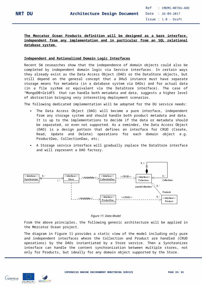
NRT DU Architecture Design DocumentRef : CMEMS-NRTDU-ADD
Date : 26-09-2017
Issue : 1.0 - Draft
a Datawarehouse, designed to provide a persistent and virtually infinite store of records;
A real-time database, designed as a rolling archive providing access with minimal delay to the parameters of interest.
The data provider is <AGE>, the data gathering function (previous paragraph).
Data consumers are:
the Mining function, for querying the data according to several criteria;
the Visualization function, for providing a graphical representation of the stored data;
The Alerting function for triggering actions based on occurrence of predefined conditions in the datastores.
III.4.2.3 Data visualization <VIS>The purpose of this function is to visualize archived data, by means of histograms, scatterplots and mimics. It is the core function allowing system monitoring. The data provider is <DBS>, the data storage function (previous paragraph). Data consumers are final users (via web-browsers).
III.4.2.4 Data mining <MIN>The purpose of this function is to retrieve data archived in the datastores. In particular, the data mining from DWH permits to create reports through ad-hoc queries. These database queries are requested by means of SQL scripts.
The data provider is <DBS>, the data storage function.
Data consumers are:
Automatic reporting system (not part of SYSMA)
Service Reporting Responsible
SYSMA administrator and operators
III.4.2.5 Alerting <ALT>The purpose of this function is to feedback authenticated users (primarily DU Service Operators and Management) about significant events related to monitored systems. The data provider is <DBS>, the data storage function. Data consumers are:
SYSMA Operator;
DU Service Management.
III.4.2.6 SysMA detailed architectureThe functions described in the previous paragraph are then associated to specific components. The association is of course arbitrary and could have been performed differently. The main objective in this case has been to minimise the number of interfaces and to have each component as much as possible decoupled from the others. In particular, in view of their implementation, deploy and operations, these components have been designed as much as possible as micro services. The components are the following:
Agents;
Data warehouse;
Real time database;
Visualization tool
Alerting tool;
Ad-hoc queries;
COPERNICUS MARINE ENVIRONMENT MONITORING SERVICE PAGE 35/ 51
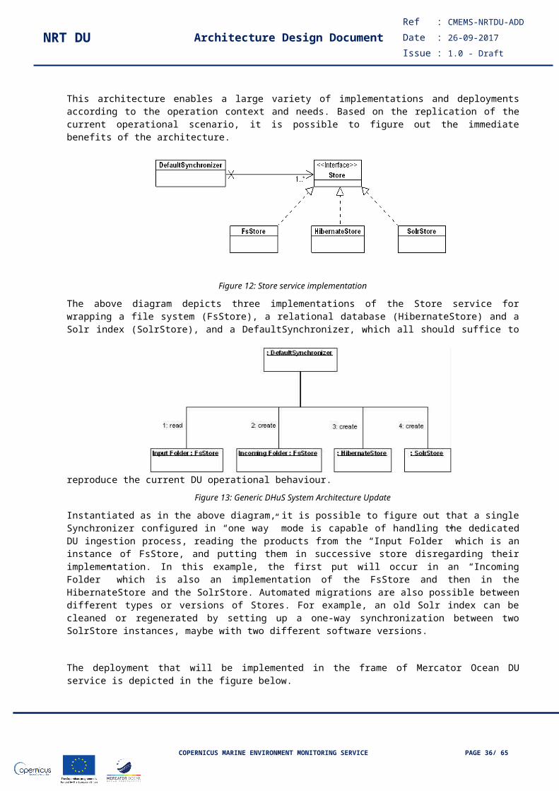
NRT DU Architecture Design DocumentRef : CMEMS-NRTDU-ADD
Date : 26-09-2017
Issue : 1.0 - Draft
Service Capacity Planning.
Figure 21 shows the SYSMA functions – components mapping matrix.
COPERNICUS MARINE ENVIRONMENT MONITORING SERVICE PAGE 36/ 51

NRT DU Architecture Design DocumentRef : CMEMS-NRTDU-ADD
Date : 26-09-2017
Issue : 1.0 - Draft
Figure 21: SYSMA functions & components mapping matrix
Functions Function ID Components COTS
Data gathering <AGE> Agents Opensource solution
Data storage <DBS> Long-term DB;
Real-time DB
PostgreSQL;
Influx
Data visualization <VIS> Visualization tool Grafana
Data mining <MIN> Ad-hoc queries Open source solution
Alerting <ALT> Alerting tool Bosun
SYSMA Agents
An “agent” is a software component developed by Serco that implements several actions via plugins. These plugins can be chosen by the SYSMA administrator and are reported in Figure 22.
Figure 22: SYSMA AGENT Plugins
Plugin Description
collectThis plugin collects infrastructural data (CPU, RAM, etc) of the machine on which it is installed.
downtime_checkerThis plugin is used to check if the system is up, making a connection to the port where the service is listening.
file_counter
This plugin counts the file in a directory.It can be used to verify how many products are present in the inbox and how many are waiting to be ingested.
log_tailerIt reads the info from a log. Principal plugin, used for DHuS application, proxy application, download managers.
service_checker This plugin is used to check if the system is up, via HTTP query.
ticket_checker The plugin retrieves ticket information from the request tracker.
usersThe plugin retrieves all user information contained in the DHuS database; information as confirmation date and deletion date are also retrieved.
product_currently_published
The plugin retrieves the number of published products contained in a DHuS instance in a certain time.
query_performancesThe plugin retrieves response time information (average, minimum and maximum) for specific bulk OData and OpenSearch queries.
scalability_monitoring The plugin retrieves the number of published products on a DHuS instance in the
COPERNICUS MARINE ENVIRONMENT MONITORING SERVICE PAGE 37/ 51

NRT DU Architecture Design DocumentRef : CMEMS-NRTDU-ADD
Date : 26-09-2017
Issue : 1.0 - Draft
Plugin Description
frame of Scalability. Data are available performing specific API queries.
Data warehouse
The long-term Data Warehouse (DWH) is a relational database. Historical data are archived in the DWH and may be further processed by SYSMA to extract derived quantities summarizing the collected data managed by the DU operational service components.
All stored long-term data (both direct and derived) are kept indefinitely in the Data Warehouse and can be downloaded as files in standard format (e.g. json).
Real time database
The real time database (RTDB) is a time-series database implemented using Influx. All data in the real-time database are stored as time series, and may be retrieved with queries. The set of parameters stored by SYSMA will be documented in to a dedicated SYSMA ICD.
Visualization tool
Data visualization from the RTDB is implemented by the SYSMA visualization tool. It uses Grafana, an open source graphing application. Grafana is the most commonly used application for visualizing time series data. It permits to create, explore, and share dashboards.
Alerting tool
By means of the alerting tool, SYSMA constantly interrogates the monitored systems to verify the occurrence of all configured alarm conditions. The alerting tool is implemented using the Bosun tool that interacts with the RTDB and is able to send notification via e-mail and / or SMS.
Ad-hoc queries
The purpose of this component is to extract relevant information from the long-term DB (DWH component), and make them available to a series of reporting applications, e.g., Weekly, Quarterly, Service Annual Reports, SYSMA Dashboard.
Service Capacity Planning
Dedicated SYSMA agents will get relevant information from OVH APIs (Back Office Console) and from Service applications to evaluate the current workload and establish the capacity planning.
SysMA data exchange
In this Section we describe the SYSMA data exchange, between both internal SYSMA components and between SYSMA and the external world.
The specific identified SYSMA interfaces are:
External interfaces: the ones between SYSMA and the external entities;
Internal interfaces: the ones that connect the internal components of SYSMA.
SysMA users
SYSMA users are all the entities (single persons, groups, institutes, etc.) that have rights to access SYSMA and its data. Access to data is granted only to users registered with the system. In summary, SYSMA users are:
Operators: they utilise SYSMA to monitor the applications constituting the DU operational baseline. They have extended functionalities allowing them to manage the system, for example they may design and implement ad-hoc views and dashboards to support analysis and troubleshooting.
COPERNICUS MARINE ENVIRONMENT MONITORING SERVICE PAGE 38/ 51
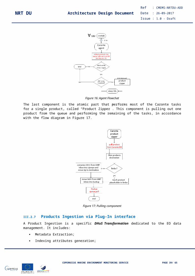
NRT DU Architecture Design DocumentRef : CMEMS-NRTDU-ADD
Date : 26-09-2017
Issue : 1.0 - Draft
Moreover, they receive, acknowledge and process SYSMA alarms;
Management: DU Service project manager, requiring a comprehensive view of the service;
Customer: the Customer is interested in monitoring the DU service and requires regular reporting (weekly, quarterly and annually);
IIV team: monitoring functions are used for the test phases;
Stakeholders: they require an overview of the DU service via on-line reporting.
Dashboard Manager: in charge of creating the content for the DU dashboards.
III.4.2.7 Dashboard Architectural Description
The web dashboard is a client running in the web browser and it is designed according to the following drivers:
Open web standards;
No framework;
Data-driven transformations;
Data binding to DOM;
Cross Browser/Cross Devices Application.
A web dashboard is composed by the HTML page that designs the final layout of the page. The layout is composed by graphical objects implementing the specific data visualization styles. The data visualization object is composed by a widget that has the own connector to get the input data. The Mercator Ocean Dashboard acts as a client getting the inputs, as json files, from the SYSMA Long Term Data warehouse.
Graphical Object
SYSMA Long-Term Data Warehouse
HTTP Get Data (REST API)
...
json
Widget
Connector
Web DashboardClient#1
Graphical Object
Widget
Connector
Web DashboardClient#2
Graphical Object
Widget
Connector
Web DashboardClient#N
Figure 23: Dashboard architecture
The proposed architecture offers several benefits: open Web Standards: no framework dependency, cross devices/cross browser access, Data export directly from browser.
III.5 MFC sub-DU NRTRefer to OBS sub-DU
COPERNICUS MARINE ENVIRONMENT MONITORING SERVICE PAGE 39/ 51

NRT DU Architecture Design DocumentRef : CMEMS-NRTDU-ADD
Date : 26-09-2017
Issue : 1.0 - Draft
III.5.1 Rationale
III.5.2 Module architecture
III.5.3 Guidelines for implementation
III.5.4 Monitoring rules
III.6 OBS sub-DU NRT
III.6.1 RationaleThe OBS sub-DU is based on the deployment of the CMEMS Dissemination Unit Gateway (DU GW) component, which provides all necessary CMEMS standard functions (download and visualization) as shown in following figure.
Figure 24 - CMEMS-NRT-OBS/MFC sub-DU
III.6.2 Module architectureThe CMEMS-NRT-OBS/MFC sub-DU runs as Virtual Machine in a cloud environment (see section II.6 for the sizing).
COPERNICUS MARINE ENVIRONMENT MONITORING SERVICE PAGE 40/ 51
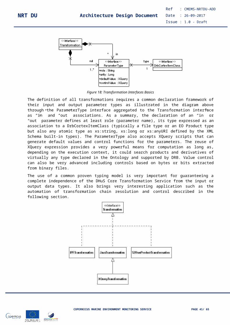
NRT DU Architecture Design DocumentRef : CMEMS-NRTDU-ADD
Date : 26-09-2017
Issue : 1.0 - Draft
The architecture foresees scalable number of VMs with same configuration (min 2) for granting component’s robustness and improving performances. The sub system will scale depending on the performances obtained during Task 1.
The CMEMS-NRT-OBS/MFC is configured for contributing at the overall performances requested by the project:
adapt configuration according to specific REQs
According to the DU GW Installation and Configuration Technical Document, Products are organized in Datasets and Products, as dataset collections. CMEMS-NRT-OBS/MFC reflects this organization.
The CMEMS-NRT-OBS/MFC configures 4 different interfaces for each dataset:
Authenticated FTP (aka MFTP)
Authenticated subsetter (aka “MOTU”, provided by DU GW)
Direct Get File (DGF),
Unrestricted WMS
Each dataset has the same temporal coverage and the same name on all CMEMS standard technical interfaces (in general: same configuration). Concerning the online temporal coverage (product reachability), the CMEMS-NRT-OBS/MFC provides:
two years of rolling archive (sliding time window) - since “last-REP’s-day” to “present-day”
rollout archive policy
In order to provide coherent dashboards, logs are centralized (remote sys-logging). Access to these logs are described in “Error: Reference source not found” section
III.6.3 Guidelines for implementation
III.6.4 Monitoring rules
III.7 INS sub-DU NRT
III.7.1 Rationale
III.7.2 Module architecture
III.7.3 Guidelines for implementation
III.7.4 Monitoring rules
III.8 Backup System
III.8.1 RationaleThe Backup module provides business continuity functionalities in case of unavailability of the Dissemination Unit.
The Backup module can play the role of the Dissemination Unit in case of disaster, i.e. a significant fraction of the Dissemination Unit is lost and cannot be set back in operation within an acceptable time range and with a possible re-deployment of the DU modules in a new physical environment.
COPERNICUS MARINE ENVIRONMENT MONITORING SERVICE PAGE 41/ 51
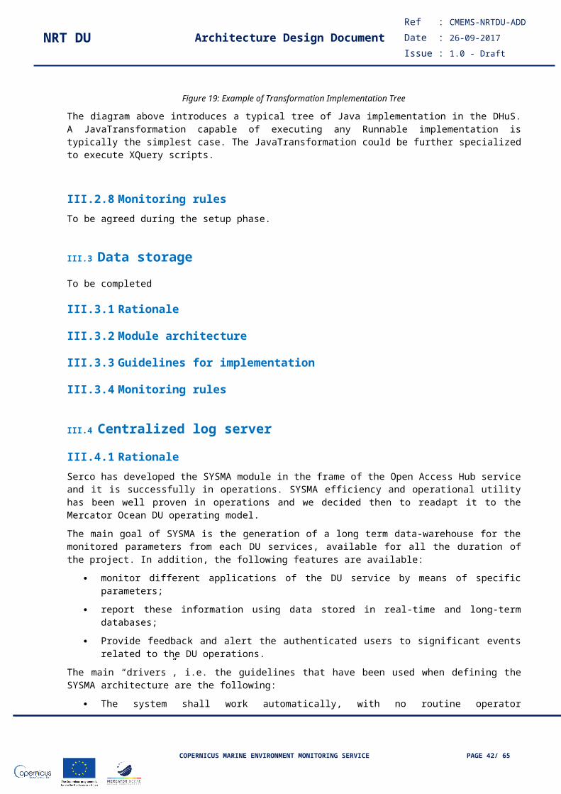
NRT DU Architecture Design DocumentRef : CMEMS-NRTDU-ADD
Date : 26-09-2017
Issue : 1.0 - Draft
The Backup System must be deployed in a different environment than the nominal DU. Any disaster occurring at DU level shall not have any impact on the Backup System availability.
The design of the backup solution is based on a smooth approach of a Backup System module deployment in three steps during the lifetime of the service.
Backup System (launch phase)For the initial launch in production phase, the Backup System will not be included. This means that if associated Dissemination Units fail to boot a part or the entire service, the user will encounter a service outage. Users must wait until all services recovery before reaching the retrieval service. As volumes used inside the Data Storage are persistent, users might have access to already process data stored by the Dissemination Unit if the failure is between the PUs and the DU.
Depending of the speed of data processing and the user request, the full recovery (having a Dissemination Unit up-to-date) may take time and thus users experience could be impacted: depending of the data transfer rules, it may also occur that the service will not be able to deliver the latest data provided by the Production Units until the backlog has been transferred fresh data shall be transferred first.
In this case, users accessing the application should be notified of the possible impact of the outage.
Backup System (planned for the operational phase)In a 2nd production phase, we will plug a dispatcher in the Delivery Buffer in order to feed the Disaster Backup module. Data will be cloned and copied into hard disks in order to create the Backup. The Backup is mainly composed of FTP (File Transfer Protocol) servers that can be extended if we have several users requesting the application. As defined below, the only limitation of this solution is the bandwidth we can attribute to each user for retrieving data.
Even for the Disaster FTP module, we provide a solution to fit the requirements of having multiple users (up to thousands) by using horizontal and vertical scalable architecture.
The module is based on widely known open source software that are the most performant and reliable for building a high available FTP platform. Build with a growth in mind design for supporting a huge amount of users and data. It is also very simple to increase physical resources by using virtualized machines (VMware solution).
In addition the Backup Data Storage is secured via RAID to guarantee system robustness. Note: when storage component is deployed in a cloud environment the high availability of the data is guaranteed by cloud functionalities (data mirroring, erasure coding, …)
FTP platforms are accessed via a light and efficient Load Balancer that is transparent for the users. This Load Balancer is in charge of re-routing the traffic to FTP servers that have the least number of connections.
Please find below the specified diagram to ease the comprehension of the clustered FTP module for the Backup System.
Figure 25 – Backup System – Architecture (phase 2)
This solution is sufficient if the Dissemination Units are never in a long term outage, as long as these outage are compatible with the SLA.
COPERNICUS MARINE ENVIRONMENT MONITORING SERVICE PAGE 42/ 51
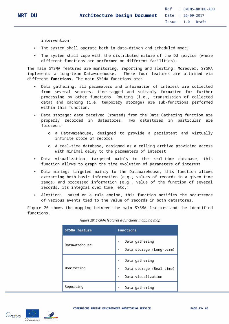
NRT DU Architecture Design DocumentRef : CMEMS-NRTDU-ADD
Date : 26-09-2017
Issue : 1.0 - Draft
However, if a corruption occurs at the Delivery Buffer level (software bugs, failover, hardware issues), it is not guaranteed that the data will be present in the Backup System as its data source is located inside the DU. It means that the data has to be provided to both DU and Backup System in parallel from a new module, external to the DU.
Backup System (high availability system)As discussed above, the data has to be provided to both nominal DU and Backup System in parallel.
One solution could be to implement this double copy at PU level. But this is an extra constraint that is not currently included as a functional requirement to the PUs.
A possible solution is to deploy an interface module between the PUs and the DU that will play this role, i.e. it receives the data flow from the PUs and generates the two copies for the DU and the Backup System. This approach is currently used in the frame of the ESA EO Data Archiving System where several living missions provides NRT data to a specific front-end that generates copies to the ESA cold archive and to the EODAS service.
The broker is designed to support a pre-defined system outage with an efficient capability to recover data while we have possible failures on the overall MO environment. Failures can be multiple and also includes cases where we want to reboot services and upgrade software versions.
The core of the broker module is based on a message system that ensures that all data within a certain time range are kept in memory (RAM or HDD). This message broker system is a robust, replicated and very fast response time messaging system. But it can only deal with a pre-defined limited amount of data (few days/weeks). This broker is able to deliver a huge amount of data per hour. Moreover data that have been ingested by the broker system can be replayed on a fresh Data Storage or can be used to explicitly recover a given time range.
Figure 26 – Backup System – Architecture (phase 3)
Messages or files stored into the broker can are always accessible. This is performed by using states and transitions within a context server that is associated to the broker. As the context server is a very lightweight storage system, we can easily monitor and quickly retrieve data enqueued/dequeued on both Delivery Buffer and Backup components.
For applications connected to the broker that failed during execution, they are also able to recover data they missed, as the broker is keeping data.
COPERNICUS MARINE ENVIRONMENT MONITORING SERVICE PAGE 43/ 51

NRT DU Architecture Design DocumentRef : CMEMS-NRTDU-ADD
Date : 26-09-2017
Issue : 1.0 - Draft
Errors at ingestion time can also be managed by the broker and it is possible to re-enqueue data if the error is of type outage.
Several tools are commonly used to achieve this goal and one that fits our need can be the Apache Kafka broker.
Note: during the consolidation of this solution, the location of the data broker will be discussed, with MO cloud environment as the prime candidate.
III.8.2 Module ArchitectureBackup System Module Functional DescriptionThe following diagram describes the components that are linked to the modules shown above. We give in detail for each component, a description and what input and output are related to them.
Figure 27 – Backup System – Logical Architecture Diagram
III.8.2.1 Load Balancer
III.8.2.1.1 Description
The Load Balancer is acting as a proxy for redirecting the traffic to an instance of FTP Server. As the Load Balancer will be the frontend of the Backup System Architecture. We will consider not only the traffic balancing but also the encryption security (e.g ftps protocol or sftp) inside this module.
III.8.2.1.2 Input
Request of FTP type from an external User.
COPERNICUS MARINE ENVIRONMENT MONITORING SERVICE PAGE 44/ 51

NRT DU Architecture Design DocumentRef : CMEMS-NRTDU-ADD
Date : 26-09-2017
Issue : 1.0 - Draft
III.8.2.1.3 Output
The external user will be redirected to a dedicated FTP Server.
III.8.2.1.4 Components
Name Description Interface provided/ uses an external interface
DU_BS_I_PROXY_Connexion Anonymous users can connect to the Proxy Server. Usage of usual FTP tools for accessing the interface.
Internal
DU_BS_C_PROXY_Load_Balancing Users will be redirected transparently to an available FTP server that has the least connexions after accepting the encryption protocol.
Internal
DU_BS_C_PROXY_Monitoring The Proxy Server will be monitored to ensure that the service is up. Internal/external
DU_BS_I_PROXY_Access Configuration of the Proxy Server may change (e.g adding a new FTP Server). We need an access interface to change Proxy configuration.
Internal
III.8.2.2 FTP Server
III.8.2.2.1 DescriptionThe FTP Server is embedded in a Virtual Machine for scaling purpose and provides links to volumes (disk space) that are mounted by using a distributed file system as NFS. An instance of FTP Server can easily be cloned by using VM tool to support multiple users on the Backup System. Of course the Proxy Server must be aware of this new FTP Server.
III.8.2.2.2 Input
Request of type FTP from the Proxy Server.
III.8.2.2.3 OutputThe user is able to view and download data from repositories handled by the Data Storage. Or the user is rejected from the FTP Server because credentials are not correct.
III.8.2.2.4 Components
Name Description Interface provided/ uses an external interface
DU_BS_I_FTP_Authentification_Authorization As the user gets redirected to an FTP Server, the server will check if the user has the required credentials.
Internal
DU_BS_C_FTP_Server Users will have read access to folders and files stored on the data storage. Internal
DU_BS_C_FTP_Folders_Configuration Folders from different volumes will be accessible from the FTP server. Meaningful paths should be defined to ease data access.
Internal
DU_BS_C_FTP_Monitoring FTP Servers will be monitored to ensure that services are up. Internal/External
COPERNICUS MARINE ENVIRONMENT MONITORING SERVICE PAGE 45/ 51
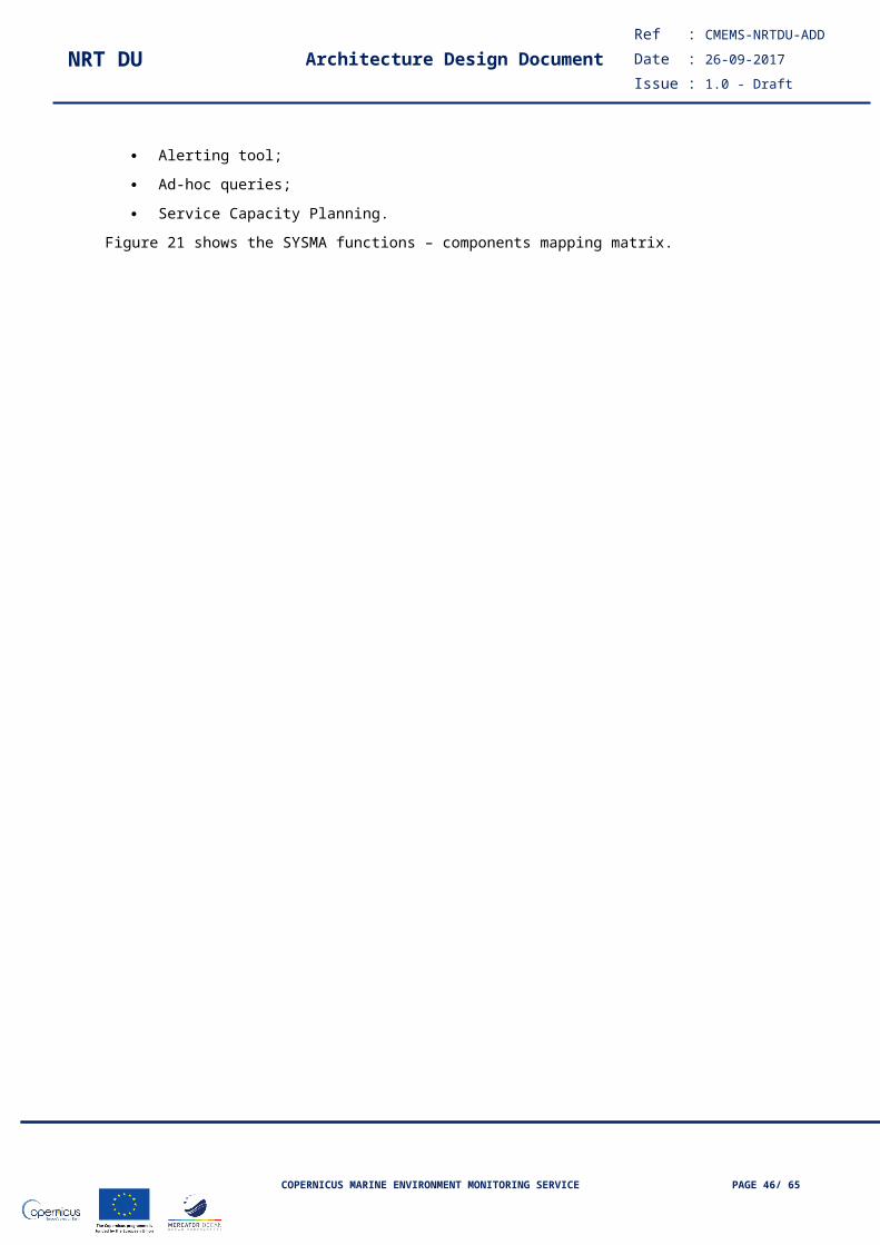
NRT DU Architecture Design DocumentRef : CMEMS-NRTDU-ADD
Date : 26-09-2017
Issue : 1.0 - Draft
DU_BS_I_FTP_Access Configuration of FTP Servers may change (e.g number of connections allowed by user). We need an access interface to change FTPs configuration.
Internal
III.8.2.3 Data Storage
III.8.2.3.1 DescriptionData storage will be based on classical NAS components with RAID-6 architecture.
III.8.2.3.2 Input
Targeted by the FTP server module.
Targeted by the Dissemination Unit or the Broker.
III.8.2.3.3 OutputData hosting
III.8.2.3.4 Components
Name Description Interface provided/ uses an external interface
DU_BS_C_Broker_Acquisition A message consumer backend is in charge of de-queuing data from the Broker. If the broker is not in place, we receive directly data from DUs Service instances.The backend will support data formatting before the storing the data.
Internal/External
DU_BS_C_HDD_Storage_Configuration The storage configuration has to be defined in accordance with the required disks size.
Internal
DU_BS_C_HDD_Monitoring Disks will be monitored to ensure that are up and remains accessible. Internal/external
DU_BS_I_HDD_Access For maintenance purpose. Internal
III.8.2.4 DU Services
III.8.2.4.1 Description
Dissemination Units are in charge of delivering data to the Data Storage. We will need to add a step to format and convert the data before the storage. In the initial phase of implementation, DU Services must be up to fill continuously the Data Storage system.
Using a custom broker to get data produced by a Production Unit and consumed by a Dissemination Unit is a way to handle many failures that can occur on the Dissemination Unit. A consumer plugged on a Dissemination Unit will be in charge of de-queuing data from the Broker.
III.8.2.4.2 InputFeed by the Production Unit or a Broker consumer.
COPERNICUS MARINE ENVIRONMENT MONITORING SERVICE PAGE 46/ 51
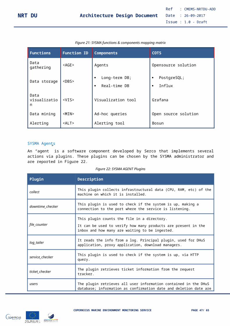
NRT DU Architecture Design DocumentRef : CMEMS-NRTDU-ADD
Date : 26-09-2017
Issue : 1.0 - Draft
III.8.2.4.3 OutputSending data to the Data Storage.
III.8.2.4.4 Components
Name Description Interface provided/ uses an external interface
DU_BS_C_Data_Formatting Data conversion and re-formatting will be required before storing files. Internal/External
DU_BS_C_Check_Running_Status The Backup system depends on the Dissemination status and should be always notified in case of the failure impacts the usual data retrieval process.
Internal/External
DU_BS_C_Monitoring Ideally the monitoring tool associated to a DU Service could automatically take over for switching to the Backup system in some cases.
Internal/External
DU_BS_C_Broker_Acquisition A message consumer backend is in charge of de-queuing data from the Broker. If the broker is not in place, we receive directly data from Production Units instances.
Internal
III.8.2.5 Broker
III.8.2.5.1 Description
A clustered Broker can be added between Production Units and DU Services. The main advantage of having this kind of server in front of both modules is that we can stop all services for a defined elapsed time as the condition that the broker and Production Units are up.
In fact the Broker is acting like a Buffer data server that is in charge of delivering the same data to one or several applications. As the Broker resource impact is very low and limited compared to the Backup System and the Dissemination Unit, it can seed much more amount of data to applications de-queuing from it.
Data are stored into the Broker and each application connected to the Broker will manage its own position within the queue. This is done by a context server that stores the offset of consumer backends each time data is read from the queue. This broker framework allows each consumer backend to process data independently.
While stopping an application or all services connected to the Broker, the recovery is ease because of no loss of data during the reloading time of any application. Once an application is up, it reads its offset and starts the de-queueing from it.
We also can use the Broker to accelerate the de-queuing speed by setting up more consumer backend for the same Queue.
COPERNICUS MARINE ENVIRONMENT MONITORING SERVICE PAGE 47/ 51

NRT DU Architecture Design DocumentRef : CMEMS-NRTDU-ADD
Date : 26-09-2017
Issue : 1.0 - Draft
Figure 28 – Backup System – Broker feeding the Data Storage module & the DU Services
III.8.2.5.2 InputFeed by Production Units
III.8.2.5.3 Output
Sending data to the Data Storage
Sending data to Dissemination Services
III.8.2.5.4 Components
Name Description Interface provided/ uses an external interface
DU_BS_I_Broker_Monitoring The broker has to be monitored carefully as it the only point of failure that can cause a full outage.
Internal
DU_BS_I_Broker_Configuration Broker topology can be changed dynamically to increase/adjust de-queuing speed.
Internal
DU_BS_C_Broker_Acquisition An instance of a broker consumer that de-queues data from the Broker queue. Internal
DU_BS_C_HDD_Data_Formatting A dedicated Data formatting can be required for each Broker consumer. For instance, we will format the data before saving it on disk.
Internal/External
DU_BS_C_Data_Formatting A data formatting/conversion between the Broker consumer and the DU Service can be performed. As example, de -compression of the data before sending it to a DU, de-serializing data before DU ingestion.
Internal/External
COPERNICUS MARINE ENVIRONMENT MONITORING SERVICE PAGE 48/ 51

NRT DU Architecture Design DocumentRef : CMEMS-NRTDU-ADD
Date : 26-09-2017
Issue : 1.0 - Draft
III.8.3 Guidelines for implementationIn order to have a heterogeneous architecture, we will use tools already present in the initial document and software we currently use in production. For the Backup System, we have four main parts to consider:
- The Load Balancer targeted by the User
- The FTP Server that will provide the download interface for data files
- Monitoring of the activity
- The RAID storage system mounted on NFS (details will not discussed here as it must be defined first)
The following description is explaining a usage of an efficient Proxy (Haproxy) and several instances of reliable FTP servers (VSFTPDs). Several instances of FTP Servers are deployed by cloning the initial Virtual Machine where a FTP Server is hosted. All FTP Servers cloned are linked to the RAID disks architecture with NFS mount.
When a user requests the access to the ACRI FTP module, he always targets the Haproxy. The proxy is in charge of checking the list of FTP servers available and redirect incoming users traffic to an FTP server (the method of load balancing used here is the least connexion).
After balancing the traffic to a VSFTPD instance, credentials of users will be check on the Active Directory (here LDAP protocol over SSO). If the username and the password exist in the AD, then the access is granted and the user is redirected to the download path folder with only read permission.
If the user is not present in the AD, then we continue the authentication process by checking if the username/password is contained into the DB5 database (our local user database). If the user exists in the local user database, then write access is granted to the user on an isolated folder.
If the username/password is not in the AD or neither in the Local user database, then the access is rejected.
A need of local user can fit many use cases. For example we can use a local user to perform sanity checks on the FTP server (is the download file working internally?). This can help in case of investigation; therefore we are sure that our FTP server is up (e.g the issue could be with the internet provider).
Figure 29 – Backup System – User access
III.8.3.1 Software configuration
HAproxy
Configuration definition Values to assign
Number of ips/ports to load balance FTP servers has to support 800 concurrent users
COPERNICUS MARINE ENVIRONMENT MONITORING SERVICE PAGE 49/ 51
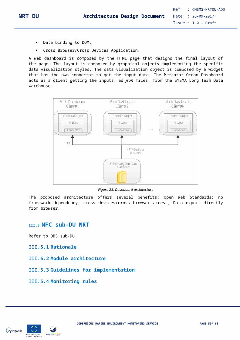
NRT DU Architecture Design DocumentRef : CMEMS-NRTDU-ADD
Date : 26-09-2017
Issue : 1.0 - Draft
Routing method Least conn users
Frequency of checking response from listed FTP Servers Less than 60 seconds check (ensure that FTP Servers VMs are up)
Monitoring service activity Nagios reporting tool
Logs monitoring HAproxy logs provide information on the requested protocol, the client ip, client location, the ip address redirection
Maximum users per FTP Server Has to be adjusted depending on the HW configuration and the bandwidth allocation
FTP Server(s)
Configuration definition Values to assign
User max session duration 72 hours
User encryption method FTP, FTP-S or SFTP
FTP mode Passive mode, will manage internally ports dedicated to download
Authentication System SSO on LDAP protocol
Max threads per users Must be adjusted (latency/bandwidth)
Folders Access All users will have the same NFS mount configuration
TCP window Has to be adjusted (depending on the internet provider and the route taken to target the Backup System)
Monitoring service activity Nagios reporting tool
Logs monitoring Provide logs for the authentication process, download completion.
List of tools already in present and that can be re-used in the Backup System:
HAproxy is the Load Balancer used for building this platform. Effective and reliable for huge traffic, it is also the most common Load balancer used in private and public companies for non http like protocol.
Vsftpd is the ftp server preferred for this project as it has to support huge amount of connections and data transfers.
Other tools used in ACRI-ST hat require more configurations/development to archive a resilient Backup System:
Nagios is a resource monitoring tool that is user friendly and helps to gain in proactivity by raising alerts when the architecture needs to be enhanced.
Kafka is a clustered message broker system that guarantees the delivery of any message and offers a robust, reliable and fast access solution for big data projects.
III.8.4 Monitoring rulesWe have identified two categories of logs for the Backup System, application logs and hardware monitoring logs. This chapter describes a possible monitoring solution that can be deployed in case the generic monitoring tool deployed for the overall CMEMS system cannot be applied.
For the hardware monitoring tool, we propose the usage of Nagios as we already have many systems configured in production on ACRI-ST using this solution.
Figure 30 – Backup System – Nagios example
COPERNICUS MARINE ENVIRONMENT MONITORING SERVICE PAGE 50/ 51
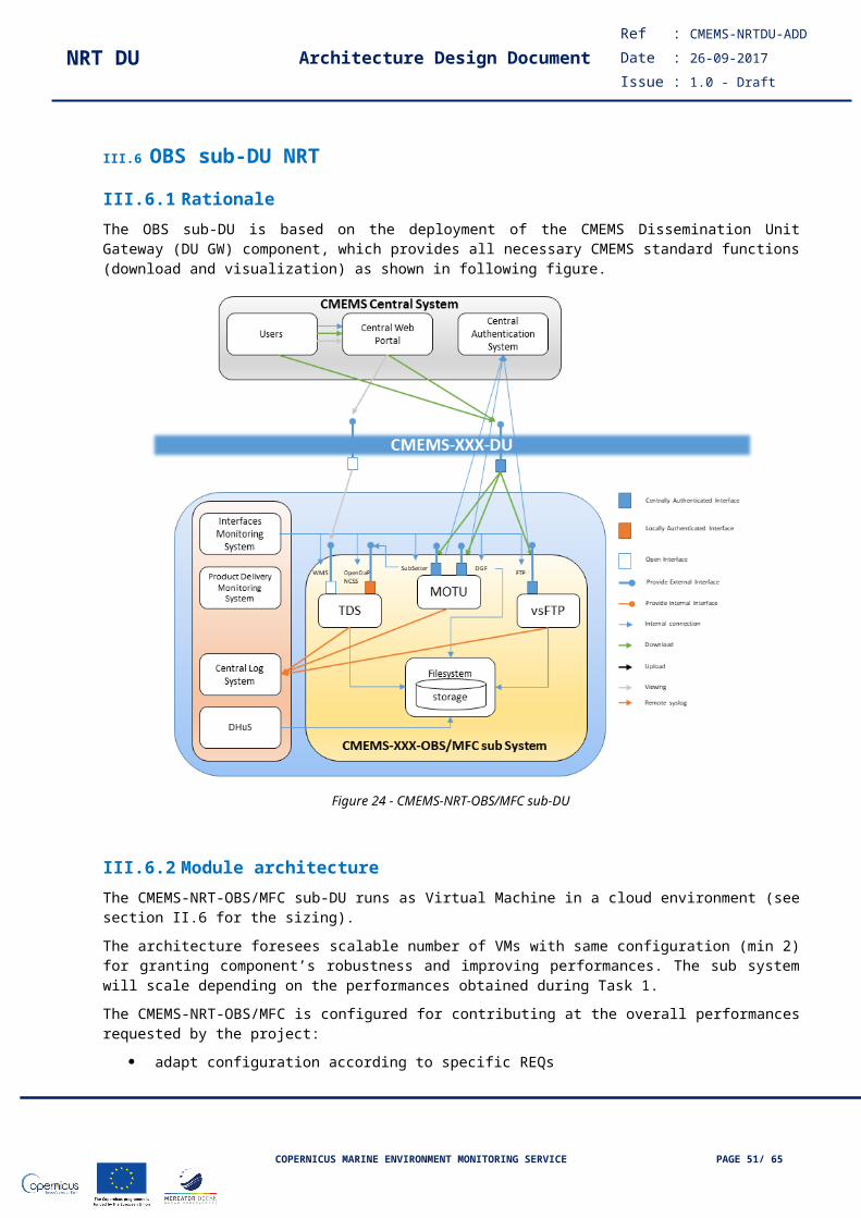
NRT DU Architecture Design DocumentRef : CMEMS-NRTDU-ADD
Date : 26-09-2017
Issue : 1.0 - Draft
For the applicative logs, we need a centralised system that will aggregate logs over FTP nodes. We can still configure Nagios as an interface to keep all our data logs. But if we need to do on-demand statistics, we will have to provide dedicated scripts for logging into Nagios.
We propose a free open source suite ELK (LogStash + ElasticSearch + Kibana) that is efficient for managing and creating on-demand reports that can be use in production. The ElasticSearch mode is able to perform live filtering and simple operations that is useful to track in real time the Backup System activity. Also we can create and share dashboards by using the Kibana interface. This interface contains graphs define by the user himself. One major advantage of this suite is the flexibility of this tool.
Figure 31 – Backup System – Applicative Logs aggregation
Figure 32 – Backup System – Kibana dashboard example
COPERNICUS MARINE ENVIRONMENT MONITORING SERVICE PAGE 51/ 51