Embed Size (px)
Citation preview
AWS: American Welding Society: www.aws.orgASME: American Society of Mechanical Engineers www.asme.orgAISI: American Iron & Steel Institute www.steel.orgISO: International Organization for Standardization www.iso.orgEN: European Standards www.cenelec.euDIN: German Institute for Standardization www.DIN.de/enDS: Danish Standard Association: www.ds.dkSIS: Swedish Standards Institute www.sis.seASSDA: Australian Stainless Steel Development Association www.assda.asn.auNIDI: Nickel Institute www.nickel-institute.orgSSINA: Specialty Steel Industry of North America www.ssina.com3-A Sanitary Standards: www.3-a.orgEHEDG: European Hygienic Engineering & Design Group www.ehedg.orgUSFDA: Food and Drug Administration in the US: www.fda.govISPEE: International Society of Pharmaceutical Engineers. www.ispe.orgBSSA: British Stainless Steel Association: www.bssa.org.uk/index.htm
Codes and Standards
Codes and Standards
Codes and Standards
BioProcessing Equipment (BPE) Standard
The ASME Bio-Processing Equipment (ASME BPE) is an international standard recognized in over 30 countries. This standard provides the requirements applicable to the design of equipment used in the bioprocessing, pharmaceutical, and personal care product industries, including aspects related to sterility and clean-ability, dimensions and tolerances, surface finish, material joining, and seals. These apply to:a) components that are in contact with the product, raw materials, or product intermediates during manufacturing, development, or scale-up;b) systems that are a critical part of product manufacture [e.g., water-for-injection (WFI), clean steam, filtration, and intermediate product storage].
Topics in the standards include:•General Requirements •Design for Sterility and Clean-ability•Worldwide Accepted Dimensions and Tolerances for Stainless Steel Automatic Welding and Hygienic Clamp Tube Fittings and Process Components•Material Joining •Stainless Steel and Higher Alloy Interior Surface Finishes •Equipment Seals •Polymer-Based Materials •Certification •Metallic Materials of Construction for Hygienic Processes •Rouge and Stainless Steel •Passivation •Electro-polishing •Bioreactor/Fermentor Design •Sterilizer/Autoclave Design •CIP and Process Gas Distribution Systems
Codes and Standards
The European Hygienic Design Group (EHEDG) is the primary organization for food equipment approval in Europe. While EHEDG has published a series of guidelines for the construction and design of food processing equipment, they have chosen not to issue standards. Acceptance for food processing equipment used in some European countries is based upon "cleanability" testing performed in EHEDG laboratories. International trade associations [e.g. International Dairy Federation (IDF)], and international standards organizations [e.g. Codex Alimentarius and the ISO are also generally involved in equipment hygiene standards. Some of these organizations have symbol or insignia use authorization programs that require third party verification of compliance with the appropriate standard or guideline.
Codes and Standards
On Sanitary processing plants the most important mater is the surface finishing it has to complies with many features to be enough smooth to do not retain any dirt or particles coming from the processing product. If this happens the system must be cleaned by CIP system (cleaning in place – method of cleaning the process equipment & associated pipe-work using a variety of cleaning agent such as RO water, Caustic, Acid and WFI (water for injection) or SIP system (method of sanitizing the process equipment & associated pipe-work by steaming at high temperature (~121°C)until certain criteria are met and all micro organism are killed)
Food equipment surfaces could be subdivided into two categories:1. Food product contact surfaces.2. Non-product contact surfaces
General
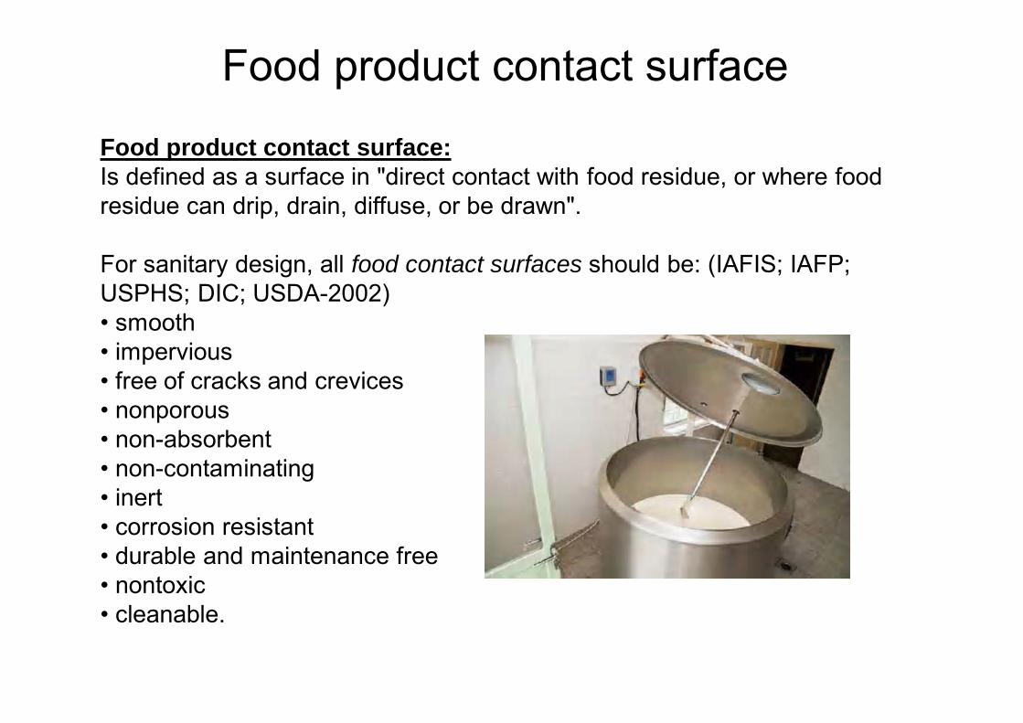
Food product contact surface:Is defined as a surface in "direct contact with food residue, or where food residue can drip, drain, diffuse, or be drawn".
For sanitary design, all food contact surfaces should be: (IAFIS; IAFP; USPHS; DIC; USDA-2002)• smooth• impervious• free of cracks and crevices• nonporous• non-absorbent• non-contaminating• inert• corrosion resistant• durable and maintenance free• nontoxic • cleanable.
Food product contact surface
Food product contact surface
If the surface is coated with metal alloy or non-metal (e.g. ceramics, plastic, rubber) in any way the final surface must meet the above requirements. • 3A Standards require that such coatings maintain corrosion
resistance, and be free of surface pitting, flaking, chipping, blistering, and distortion under conditions of intended use.
• Similarly, if any other modification or process is used at the fabrication process (e.g., welded, bonded, or soldered) it should be done using appropriate material and process to ensure the final surface meets the sanitary design criteria. (Folkmar Andersen & A/S, 2006)
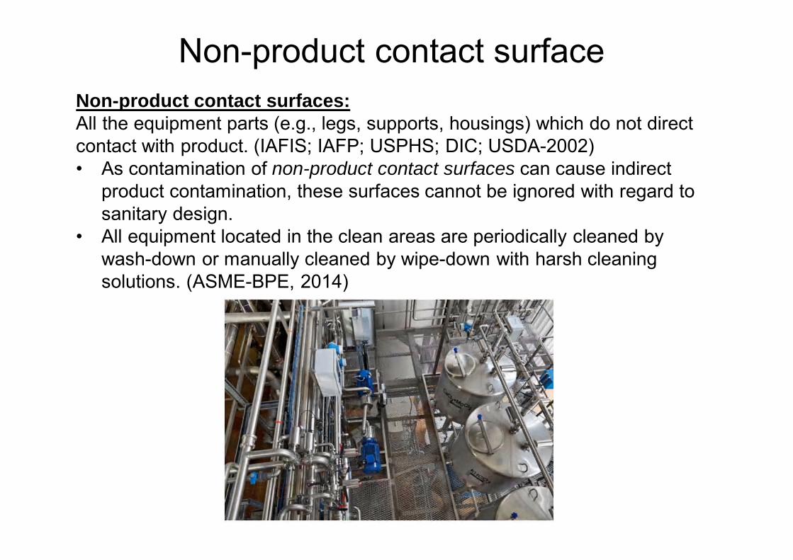
Non-product contact surfaceNon-product contact surfaces: All the equipment parts (e.g., legs, supports, housings) which do not direct contact with product. (IAFIS; IAFP; USPHS; DIC; USDA-2002) • As contamination of non-product contact surfaces can cause indirect
product contamination, these surfaces cannot be ignored with regard to sanitary design.
• All equipment located in the clean areas are periodically cleaned by wash-down or manually cleaned by wipe-down with harsh cleaning solutions. (ASME-BPE, 2014)
A variety of materials used in the equipment fabrication for different food and beverage applications. Materials vary in their properties regarding to workability.
Process Compatibility: materials of construction shall be capable of withstanding the temperature, pressure and chemical corrosiveness ensure the purity and integrity of the product as well with cleaning solutions and or SIP conditions in case it has being specified for the project designer/user. (ASME-BPE, 2014)
Stainless steel is the most suitable metal for product contact surfaces in the food and beverage applications. • The stainless steel alloy properties are related to chromium and nickel
level. Corrosion resistance varies with chromium level, and structural strength will be proportional to nickel level.
• For welding purposes is better stainless low carbon content less than 0.03% carbon contents.
Material
• There are five basic mechanisms that cause stainless steel corrosion: Uniform corrosion; Intergranular corrosion; Galvanic or general corrosion, which includes pitting and crevice corrosion; Stress Corrosion Cracking; and Microbiologically Influenced Corrosion (MIC).
• In addition there are several mechanical processes that accelerate the five basic mechanisms These include erosion, cavitation, fretting, formation of concentration cells, and changes in surface chemistry by thermal or electrical forces.
• All of these mechanisms have one characteristic in common: the chromium oxide passive layer is breached and the unprotected iron component is oxidized.
• For an understanding of the rouging phenomenon only two mechanisms will be considered: Uniform or General Corrosion and Crevice Corrosion together with erosion, cavitation and concentration cell formation.
How does stainless steel corode
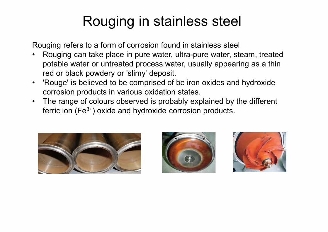
Rouging refers to a form of corrosion found in stainless steel• Rouging can take place in pure water, ultra-pure water, steam, treated
potable water or untreated process water, usually appearing as a thin red or black powdery or 'slimy' deposit.
• 'Rouge' is believed to be comprised of be iron oxides and hydroxide corrosion products in various oxidation states.
• The range of colours observed is probably explained by the different ferric ion (Fe3+) oxide and hydroxide corrosion products.
Rouging in stainless steel
1. Iron Contamination Dragging stainless steel over carbon steel will smear iron onto the surface that will rust when placed in service. Welding temporary carbon steel braces to stainless steel, then grinding off the welds results in a low chromium area that will rust in service. Using carbon steel wire brushes or grinding wheels contaminated with carbon steel will result in rust. The mechanism for the red rust formation is simple: Iron + Water = Rust. The best prevention of rust formation is common sense: always cover all carbon steel surfaces with wood, plastic or cardboard to prevent contact with the stainless steel; never weld carbon steel to stainless steel; always use stainless steel brushes and “stainless only” dedicated grinding wheels; and always chemically passivate with nitric or citric acid before placing in service. Rust can cause crevice corrosion or pitting of the stainless steel under the red oxide, therefore it must be removed. This is why passivation is necessary, not only to increase the chromium to iron ratio on the surface, but also to remove any iron contamination. Two specifications for cleaning and passivation are: ASTM A 380 “Standard Practice for Cleaning, Descaling and Passivation of Stainless Steel Parts, Equipment and Systems”, and ASTM A 967 “Standard Specification for Chemical Passivation Treatments for Stainless Steel Parts” .
Rouging in stainless steel
Treated and Untreated Waters Both treated and untreated waters can rouge, even softened water. The culprit is what is in the water, primarily ferrous bicarbonate. Softening does not remove anions like carbonate, bicarbonate, sulfates, chlorides, etc., but only exchanges the cations like calcium and magnesium with sodium or potassium. Unlike ferric carbonate, ferrous bicarbonate is completely soluble, but is easily oxidized to ferric carbonate. Ferric carbonate is insoluble and reddish brown in color. It can be dissolved in strong acids. Treated or potable (drinking) water normally is clarified to remove suspended solids, filtered to remove fines and disinfected with chlorine or chlorine dioxide to destroy most bacteria. This process has little or no effect on the bicarbonate ion as long as it is in equilibrium with the carbon steel piping and the oxygen content is low. Once the water is in an inert environment, like stainless steel or porcelain, the bicarbonate begins to oxidize: 2Fe(HCO3)2 + Ca(HCO3)2 +Cl2 ® 2Fe(OH)3¯ + CaCl2 + 4CO2 2Fe(OH)3 ® Fe2O3 + H2 Ferric oxide, Fe2O3, is red and when it occurs in nature it is called hematite. In untreated water the chemical reaction is similar, except no chlorine is present and oxygen, dissolved in the water, is the active agent. 6Fe(HCO3)2 + O2 ® 2Fe2(CO)3¯ + 2Fe(OH)2 + 4H2O + 6CO2 4Fe(OH)2 + O2 ® 2Fe2O3 + 4H2O Ferric carbonate will precipitate and the ferrous hydroxide forms a gelatinous compound that precipitates as ferric oxide. There is a slight difference in color because the ferrous hydroxide is yellow. In large tanks the reddest deposits are usually at the top and decrease toward the bottom. It is not unusual for the bottom of a large tank to be relatively clean.
Rouging in stainless steel
2. Pure and High Purity Water Pure and high purity water typically is used in industries where impurities can have a detrimental effect, such as pharmaceutical or semiconductor manufacturing. In the pharmaceutical industry it is called WFI, or water for injection. Typical treatments include filtration, softening, anion and cation ion exchange, reverse osmosis, ultraviolet and occasionally ozonation. Distillation may be used as final purification. The result is water with extremely low conductivity. Type 316L stainless steel is the usual material of construction. Some of these systems remain clean, but others begin to rouge. Even electropolished systems with an average surface roughness less than 10 micro inches (<10 m-in Ra) can rouge. In the presence of hot high purity steam these systems turn black, sometime glossy black, sometimes powdery black. conductivity. Sections of rouged stainless steel piping were obtained from a number of different pure water and steam systems. The rouge layers were examined using X-Ray Photoelectron Spectroscopy (XPS), Energy Dispersive Spectroscopy (EDS) and Scanning Electron Microscopy (SEM). The SEM allows visual examination of the surface, EDS allows spot analyses of surface anomalies, and XPS allows layer-by-layer analyses of the rouge deposits and identification of the molecular species. Comprehensive reports of the findings are given elsewhere 1,2. This work allowed rouge in pure and high purity water and steam to be classified as Class I, Class II and Class III rouge depending on the mechanism of formation
Rouging in stainless steel
3. Class I rougeClass I rouge comes from an external source. Rouge particles are deposited on stainless steel surfaces, and in the early stages of deposition can be easily wiped clean. Surface composition of the stainless steel passive layer under the rouge is unchanged from that of the originally installed system. The rouge particles usually have the same composition as the material from which the particles came, certainly not that of corroding stainless steel. Rouge concentration is heaviest near the source and decreases with distance from the source. Color of the rouge may change with distance from the source, being orange to red-orange near the source and changing to magenta some distance away. The color comes from the presence of the various iron oxides and hydroxides. The orange oxide is the lowest valence state for iron hydroxide and forms when both oxygen and water are present: 2Fe0 + 4H2O ® 2FeO(OH) + 3H2 2FeO(OH) ® Fe2O3 + H2O The metallurgical condition of the impeller seems to have an influence on the rate of metal removal. When the 18-8 family of stainless steel solidifies from the melt two metallurgical phases are present, austenite and delta ferrite. Delta ferrite formation is dependent on the composition of the alloy and if it is less than 8% it can be dissolved by heat treatment.Cast impellers generally have high delta ferrite because of higher silicon added to promote fluidity of the steel during casting. This means heat treatment may not dissolve all the delta ferrite. The reason delta ferrite is a problem is because it erodes more easily than the austenite and is higher in iron.
Rouging in stainless steel
External rouge can come from a number of sources. The most obvious is carbon steel in the system including tie rods, bolts, nuts, wrenches, staples, etc. The larger the source the more rouging that will occur. Pumps are prime suspects in an otherwise clean system. Two mechanisms appear to be the cause of pump induced rouging: cavitation and erosion because of impeller velocity. Cavitation usually results from inadequate water supply to the pump, improper pump selection, operation or excessive throttling during operation. Bubbles impact on a pump surface and implode, resulting in a shock wave that removes a small particle of stainless steel. Once the particle is free in the water stream it eventually is attached to the stainless steel piping by electrostatic attraction. Because the particle surface is not passivated, it immediately begins to oxidize and turn red. Erosion of the impeller is another possible mechanism. Every material has a critical velocity above which erosion accelerates3. For low alloy austenitic stainless steels this critical velocity appears to be around 100 fps. Erosion rate will vary with temperature. Type 304 Stainless Steel appears to have a constant erosion rate up to 600° F (300° C) then increases rapidly. Specific data in high purity water for the different alloys are not available. The metallurgical condition of the impeller seems to have an influence on the rate of metal removal. When the 18-8 family of stainless steel solidifies from the melt two metallurgical phases are present, austenite and delta ferrite. Delta ferrite formation is dependent on the composition of the alloy and if it is less than 8% it can be dissolved by heat treatment. Cast impellers generally have high delta ferrite because of higher silicon added to promote fluidity of the steel during casting. This means heat treatment may not dissolve all the delta ferrite. The reason delta ferrite e is a problem is because it erodes more easily than the austenite and is higher in iron.
Rouging in stainless steel
4. Class II Rouge This class of rouge occurs when chlorides or other halides are present. It is corrosion driven and forms on the surface of the stainless steel at the place where the passive layer is breached. It appears more often on unpassivated and mechanically polished surfaces and may display tubercles. The stainless steel under these tubercles will be very shiny and may be pitted. When material from this rouge is analyzed, chlorides or other halides usually are present. The rouge cannot be removed by mechanically except by grinding or polishing, but most often using an acid solution. Citric acid is a good cleaning agent and will repassivate the stainless steel, but if chlorides are present the surface will rouge again.Class II Rouge forms in a two stage reaction, the first is the dissolution of the chromium oxide passive layer, the second the oxidation of the iron in the substrate: Cr2O3 + 10Cl- + 2H20 ® 2CrCl3 + 4HClO 2Fe + 3ClO- ® Fe2O3 + 3Cl- This reaction is self-perpetuating by the chloride reacting with the chromium to form hypochlorousacid as a byproduct, and the hypochlorous acid oxidizing the iron and forming more chloride.
Rouging in stainless steel
Increasing the molybdenum content of the stainless steel increases the resistance to chloride attack. Likewise, replacing the iron in stainless steel with nickel improves the corrosion resistance. This is the progression of alloys with increasing resistance to chloride attack: Type 304L (least), Type 316L, Type 317L, Type 317LM, Alloy 625, Alloys C-276 and C 22 (highest). Whenever a stainless steel system comes in contact with an acid chloride there is a potential for rouging. A pH > 7 solution will have less potential for rouging than pH < 7. Even momentary exposure to an acid chloride solution may set the stage for this type rouging reaction especially if the stainless steel surface is rough. Mechanically polished surfaces are worse than electropolished surfaces because of the microscopic crevices resulting from smeared metal from the polishing operation. Electropolishing removes these microscopic crevices and produces a passive layer with a higher Cr: Fe ratio. The crevices create concentration cells where the acid chloride solutions may be retained and continue to react, even if the system is given a high pH rinse. Use of a strong surfactant in the rinse will aid in removing the chloride.
Rouging in stainless steel
5. Class III Rouge This rouge is black, not red, and forms in the presence of high temperature steam. When it first forms it is blue, then turns black as it grows to a limiting thickness that prevents further diffusion of oxygen. It may be found in high purity steam systems that operate at elevated temperatures. On electropolished stainless steel the appearance is glossy black, and on unpassivated mechanically polished surfaces it may be powdery black. Analysis, using XPS, shows this film is iron sesquioxide, commonly called magnetite. It cannot be removed by simple cleaning but must be removed chemically or by grinding. If the rouge is glossy black, then it may be left alone as it is quite stable. The powdery black film may slough-off and may need cleaning. After chemically cleaning, usually with hot oxalic acid, the surface must be chemically passivated. Once the system is back in service it will turn black once again, but hopefully not forming the powdery black film. This type of rouge is the high temperature reaction product of steam with the iron in the stainless steel forming magnetite. The reaction appears to take place in two steps: 3Fe0 + 4H2O ® FeO + Fe2O3 + 4H2 FeO + Fe2O3 ® Fe3O4 Some of the iron oxide may be replaced with nickel oxide, but the iron sesquioxide will control the color of the film
Rouging in stainless steel
Summary • Rouging of stainless steel is the result of the formation of iron oxide, hydroxide or
carbonate either from external sources or from destruction of the passive layer. Colour variation is a result of the oxide/hydroxide/carbonate type and variations in the water of hydration associated with the molecule. These colours range from orange to red to black.
• Bright red streaks on the surface of stainless steel usually are the result of iron contamination from dragging carbon steel over the surface, from welding carbon steel to the stainless steel, from iron contaminated grinding wheels or steel wire brushes.
• In untreated water the discoloration may be the result of oxidation of ferrous bicarbonate in the water forming a brownish red deposit. This oxidation may be from added chlorine or dissolved oxygen.
• In high purity water systems the rouge may be of three types: Class I Rouge originating from external sources, usually by erosion or cavitation of pump surfaces. Class II Rouge originating from chloride induced corrosion of the stainless steel surfaces. Class III Rouge, either blue or black, found in high temperature steam systems.
Rouging in stainless steel
What is mechanical polishing? Electro-polishing? Mechanical polishing – Mill finishes, welds and surfaces that have been in service have differing surface characteristics when viewed under magnification. Mechanical polishing reduces all surface ridges, pits and discrepancies to a uniform roughness. Mechanical polishing is accomplished utilizing aluminium oxide abrasives on rotary equipment. Mechanical polishing can be achieved by hand held tools for large surface areas, such as reactors and vessels in place, or by automatic reciprocating machines for pipe or tubular components. A series of grit polishes is applied in a successively finer sequence until the desired finish or surface roughness is achieved. Electro polishing is the electrochemical removal of microscopic irregularities from metal surfaces. It results in a general leveling or smoothing of the surface, that when viewed under magnification, appears virtually featureless.
Polishing (surface finishing)
As a result of electro-polishing, a metal surface exhibits the following properties: • Surface roughness is significantly reduced, thus reducing adhesion
properties. • Surface area is reduced as much as 7:1. • Surface friction and drag are reduced. • Corrosion resistance is increased due to a chromium enrichment of the
surface and the removal of surface contaminants that may promote corrosion.
Stainless steel has a natural resistance to corrosion due to its high chromium content (stainless steels are typically 16% chromium or higher). Electro-polishing enhances this natural resistance because the process dissolves more iron (Fe) than chromium (Cr). This leaves higher levels of chromium on the stainless steel surface. (Passivation)
Polishing (surface finishing)
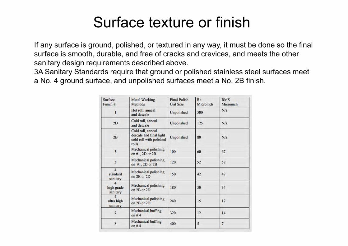
If any surface is ground, polished, or textured in any way, it must be done so the final surface is smooth, durable, and free of cracks and crevices, and meets the other sanitary design requirements described above. 3A Sanitary Standards require that ground or polished stainless steel surfaces meet a No. 4 ground surface, and unpolished surfaces meet a No. 2B finish.
Surface texture or finish
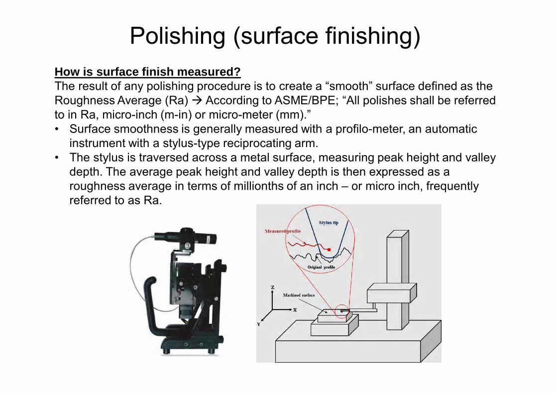
How is surface finish measured? The result of any polishing procedure is to create a “smooth” surface defined as the Roughness Average (Ra) According to ASME/BPE; “All polishes shall be referred to in Ra, micro-inch (m-in) or micro-meter (mm).” • Surface smoothness is generally measured with a profilo-meter, an automatic
instrument with a stylus-type reciprocating arm. • The stylus is traversed across a metal surface, measuring peak height and valley
depth. The average peak height and valley depth is then expressed as a roughness average in terms of millionths of an inch – or micro inch, frequently referred to as Ra.
Polishing (surface finishing)
Polishing (surface finishing)
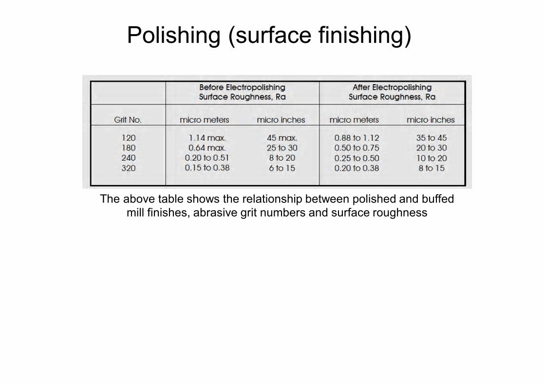
The above table shows the relationship between polished and buffed mill finishes, abrasive grit numbers and surface roughness
Polishing (surface finishing)
• Titanium has excellent durability and corrosion resistance (especially in an acidic environment). However, its use is limited by high cost. Titanium is used in stainless steel alloys for food equipment used in the processing of food products with high acid and/or salt content (e.g., citrus juice, tomato products).
• Platinum, another excellent corrosion resistant material, would also be highly desirable, but, obviously, the cost of this rare material would prohibit its use.
• Gold has been approved as a food contact surface in certain 3-A Sanitary Standards. In some cases, gold is used for soldering optical sensors (e.g., fibre optics) into stainless steel fittings. Gold is desirable in these applications for its resistance to abrasion and compatibility with glass.
Material
3A Standards also provide specifications regarding alloys and other coatings used in fabrication.
Stainless steel properties may change with continued use, especially under conditions where the chromium oxide layer is altered (e.g. incompatible cleaners, abrasive cleaners, abrasive cleaning pads, or chlorine and related sanitizers).
Therefore, it is recommended this surfaces be passivated (using nitric acid or other strong oxidizing agents) initially and on a regular frequency thereafter, to maintain a passive (non--reactive) oxide film on the surface. Passivation of stainless steel food contact surfaces is recommended after any surface repair, welding, polishing, or working.
Material
Other metals are limited by application as follows:• Copper is primarily used for equipment used in the brewing industry, with
some use for cheese vats in Swiss cheese manufacture, due to tradition. Care should be used with copper equipment when processing acid products, as copper residues can leach into the product.
• Aluminium is used in certain parts and components where lighter weight is desired. However, aluminium has poor corrosion resistance and can become pitted and cracked with continued use. Care should take when cleaning and sanitizing aluminium components as oxidizing chemicals can accelerate the pitting of the metal. In most food contact applications, aluminum must be coated with an acceptable material. Plastic coatings such as polytetrafluorethylene (PTFE or Teflon®) are common.
• Carbon steel and cast iron are only used for frying and cooking surfaces, and similar applications in food service.
• Galvanized iron should be avoided as a food contact surface because it is highly reactive with acids highly reactive with acids. (Folkmar Andersen & A/S, 2006)
Material
Material

Variety of non-metal materials are used as food contact surfaces in specificapplications of food equipment (e.g., probes, gaskets, membranes). These materials should meet the same sanitary design and clean-ability requirements as metals when used in these applications as described in 3A Sanitary Standards and other standards.Non-metal surfaces, in general, lack the corrosion resistance and durability of metal surfaces, therefore, maintenance programs should include frequent examination for wear and deterioration under continued use, and replacement as appropriate.
Non-metal materials used in food contact surfaces include:• Plastics, rubber, and rubber-like materials that should be food grade and
should meet the requirements designated under 3A Sanitary Standards (18-03 and 20-20). Multi-use plastics, rubber, and rubber-like materials may also be considered as indirect food additives under FDA regulations.
• Ceramics are used primarily in membrane filtration systems. They may also be used in other limited applications if wear resistance is necessary.
Non-metal material
• Glass may be used as a food contact surface. These applications are limited due to the potential for breakage. Specially formulated glass materials such as Pyrex® have proven successful. When glass is used, it must be durable, break resistant or heat resistant glass. Some applications where glass is used are light and sight openings into vessels and in very limited glass piping applications.
• Paper has been used over the years as a gasket material in piping systems designed for daily disassembly. Paper is considered a single use material.
• Wood, which is highly porous and difficult to clean, should be avoided as a food contact surface. Wood is restricted in food service applications by most regulatory agencies, with the exception of hardwood cutting boards and tight grain butcher blocks.
Non-metal material
Before we start with this matter is better understand certain definitions such as, clean-ability, drain-ability & Dead-leg
Clean-ability: the ability to be cleaned, especially easily or without damage, regarding to piping surface: All surfaces shall be cleanable. Surface imperfections (e.g., crevices, gouges, obvious pits) shall be eliminated whenever feasible.All surfaces shall be accessible to the cleaning solutions and shall be accessible to establish and determine efficacy of the cleaning protocol.The following provisions are applicable to tubing equipment or systems to be cleaned in place: Internal horizontal surfaces should be minimized. The equipment shall be drainable and free of areas where liquid may be retained and where soil orcontaminants could collect. The equipment shall be free of areas of low flow and velocity or impact where soil or contaminants could collect. (ASME-BPE, 2014)
Piping design
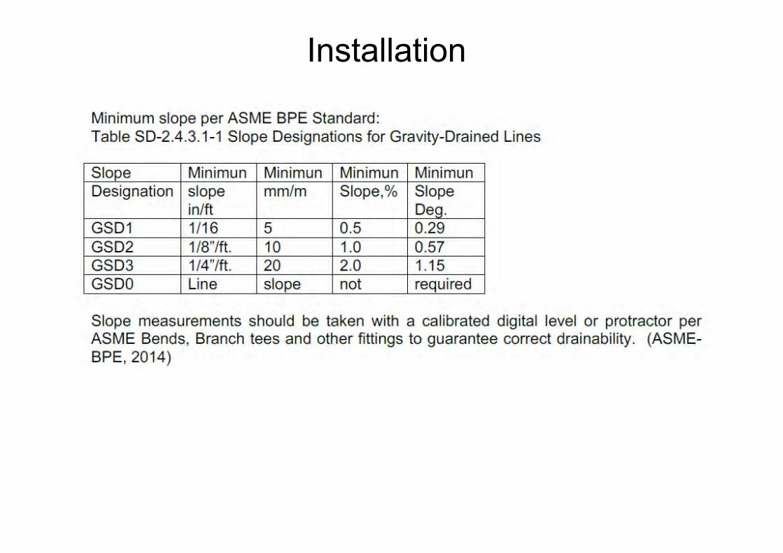
Drain-ability: the system ability to be drainage, mainly by gravity. For sterility and cleaning, gravity is an effective way to facilitate drainage. To achieve gravity drainage, lines should be pitched to designated points at the specific slope.For gravity-drained piping/tubing systems, the designer/user may define the system slope in accordance with one of the designations listed in table SD-2.4.3.1-1. (ASME- BPE, 2014)Drain-ability is important for maintaining bioprocess systems in a clean and sterile condition. Fluid remaining after draining becomes a colonization site for bacteria or other microorganisms creating an unacceptable bioburden to the system. Sites where fluid accumulates also may become a corrosion-initiation site adding additional contaminants to the system. The design Part of the ASME/BPE Standard calls for hold-up volume, or that amount of liquid which remains in the system after draining is complete, to be minimized by design.
Piping design
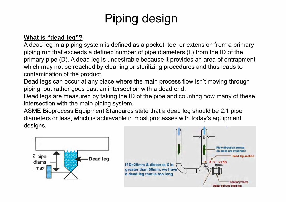
What is “dead-leg”? A dead leg in a piping system is defined as a pocket, tee, or extension from a primary piping run that exceeds a defined number of pipe diameters (L) from the ID of the primary pipe (D). A dead leg is undesirable because it provides an area of entrapment which may not be reached by cleaning or sterilizing procedures and thus leads to contamination of the product. Dead legs can occur at any place where the main process flow isn’t moving through piping, but rather goes past an intersection with a dead end.Dead legs are measured by taking the ID of the pipe and counting how many of these intersection with the main piping system.ASME Bioprocess Equipment Standards state that a dead leg should be 2:1 pipe diameters or less, which is achievable in most processes with today’s equipment designs.
2
Piping design
Pipe material and roughness has to be specified at least according with the minimum requirements following international standards by type of industry.• The inside surface should be passivated, pickled or electro-polished.
Special care should be taken when welding electro-polished surfaces as a far better gas protection is required for welding of surfaces which have been made “shiny” – e.g. through grinding, electro-polishing, etc.
• There must be no scratches, holes, porosity or other surface defects on the product side of the steel.
• Pipes must be delivered free of defects and clean on the inside as well as on the outside. The pipes must be plugged at the ends and wrapped.
• Fittings must be delivered flawless and clean on the outside as well as on the inside, and they must be wrapped.
• All pipes and fittings belonging to the same mounting operation should have identical pipe diameters and material thickness, i.e. be delivered in the same standard (DS, DIN, 3A, SMS or other). (Later a DIN pipe can, however, be welded onto a DS pipe. It only requires that the pipe with the smallest diameter be milled to the same diameter as the other pipe). (Folkmar Andersen & A/S, 2006)
Pipe work

Process piping would be installed to meet with standards:• Continuous slope for correct drain-ability• Pipe layout must be design to reduce pressure loss as low as
possible using few elbows, branch tees, etc.• Dead pockets/blind ends are not allowed.• To avoid undrainable pockets, for horizontal pipelines use
eccentric reducers to change pipe diameter. For vertical pipes use of concentric reducer is allowed. Change of pipe dimeter is not allowed without the use of proper sanitary reducers.
• For pipe expansion due temperature changes inserting a lyre or an expansion joint. Stainless steel expands by more than 1 mm per meter per 100°C heat increase.
• For correct slope Adequate spacing of supports to avoid liquids traps
Piping layout
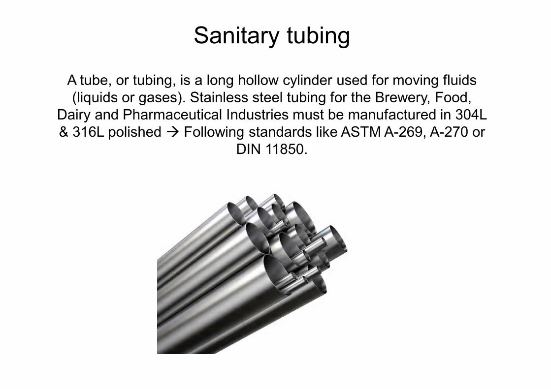
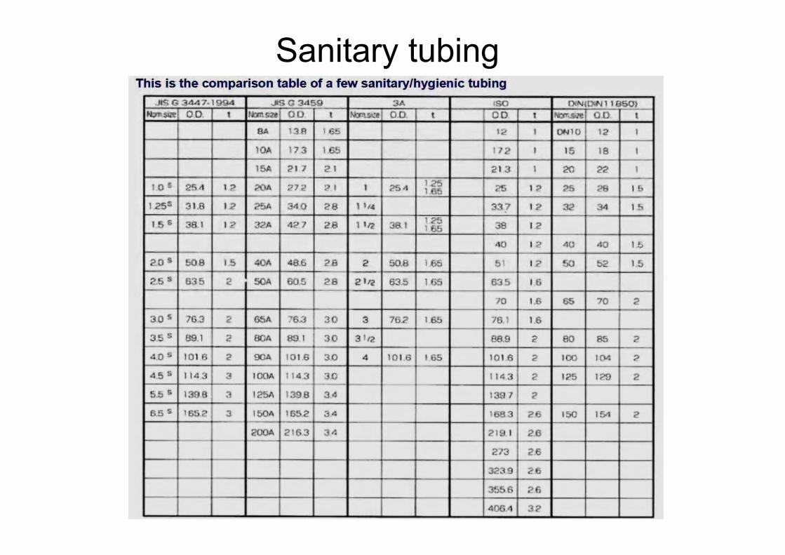
A tube, or tubing, is a long hollow cylinder used for moving fluids (liquids or gases). Stainless steel tubing for the Brewery, Food,
Dairy and Pharmaceutical Industries must be manufactured in 304L & 316L polished Following standards like ASTM A-269, A-270 or
DIN 11850.
Sanitary tubing
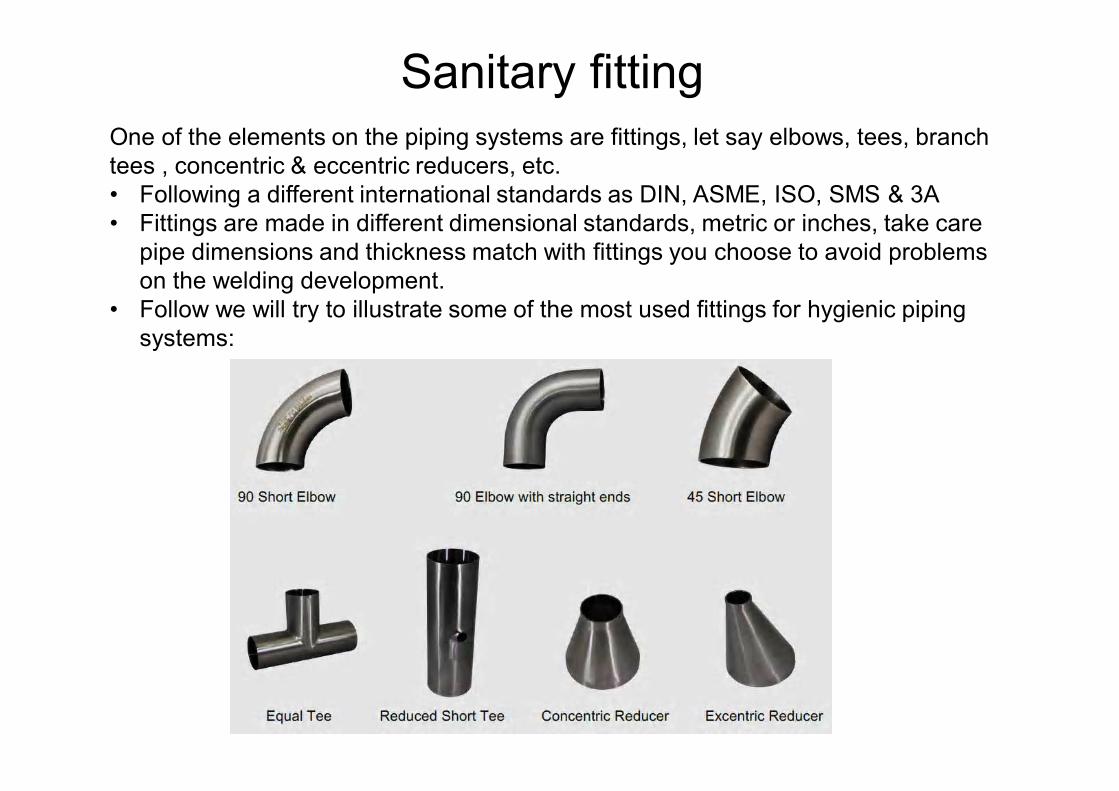
One of the elements on the piping systems are fittings, let say elbows, tees, branch tees , concentric & eccentric reducers, etc.• Following a different international standards as DIN, ASME, ISO, SMS & 3A• Fittings are made in different dimensional standards, metric or inches, take care
pipe dimensions and thickness match with fittings you choose to avoid problems on the welding development.
• Follow we will try to illustrate some of the most used fittings for hygienic piping systems:
Sanitary fitting
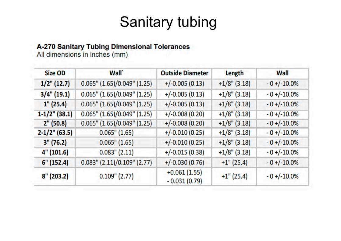
Sanitary tubing
Sanitary tubing
Food & Beverage, Pharmaceutical & Cosmetic Industry is very sensible to a process contamination due a piping sealing devices on their operational plants world-wide, becoming a management concern to keep the reasonably levels of product quality to get trust of their customers.Areas of seal intrusion or recess are caused by overtightened gaskets creating a microbial trap at the clamp union.
This cause a certain number of production problems:• Drain-ability and clean-ability of the system is being compromised• Remaining product is held in the system creating a microbial trap• Gasket Intrusion into the process stream creates damming and exposes the
gasket to get into the product• Seal failure is accelerated because increased contact area is in contact with
aggressive CIP chemicals• Risk of process contamination increases due to shearing of seal
particulates
Sanitary coupling

Sanitary clamp connection
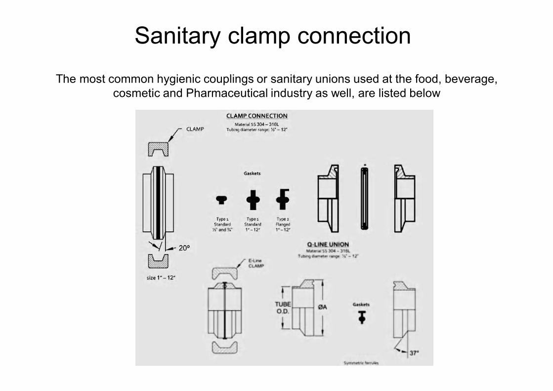
The most common hygienic couplings or sanitary unions used at the food, beverage,cosmetic and Pharmaceutical industry as well, are listed below
Sanitary clamp connection
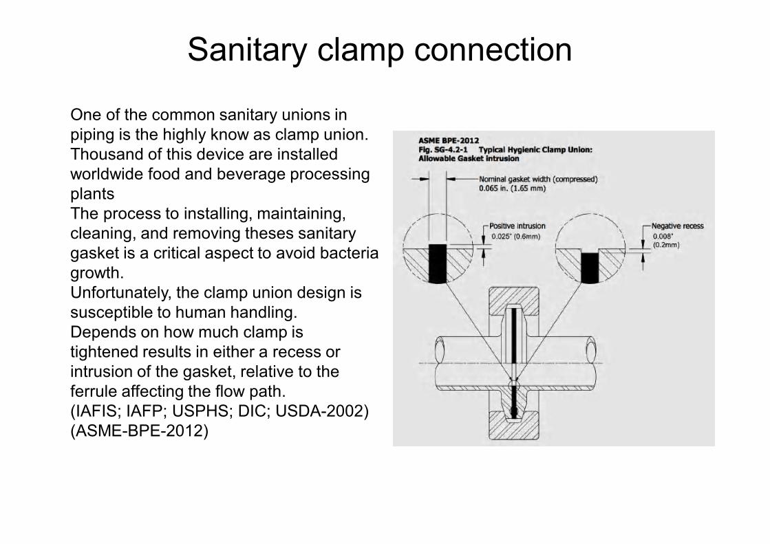
One of the common sanitary unions in piping is the highly know as clamp union. Thousand of this device are installed worldwide food and beverage processing plants The process to installing, maintaining,cleaning, and removing theses sanitary gasket is a critical aspect to avoid bacteria growth. Unfortunately, the clamp union design issusceptible to human handling.Depends on how much clamp istightened results in either a recess or intrusion of the gasket, relative to the ferrule affecting the flow path.(IAFIS; IAFP; USPHS; DIC; USDA-2002) (ASME-BPE-2012)
Sanitary clamp connection
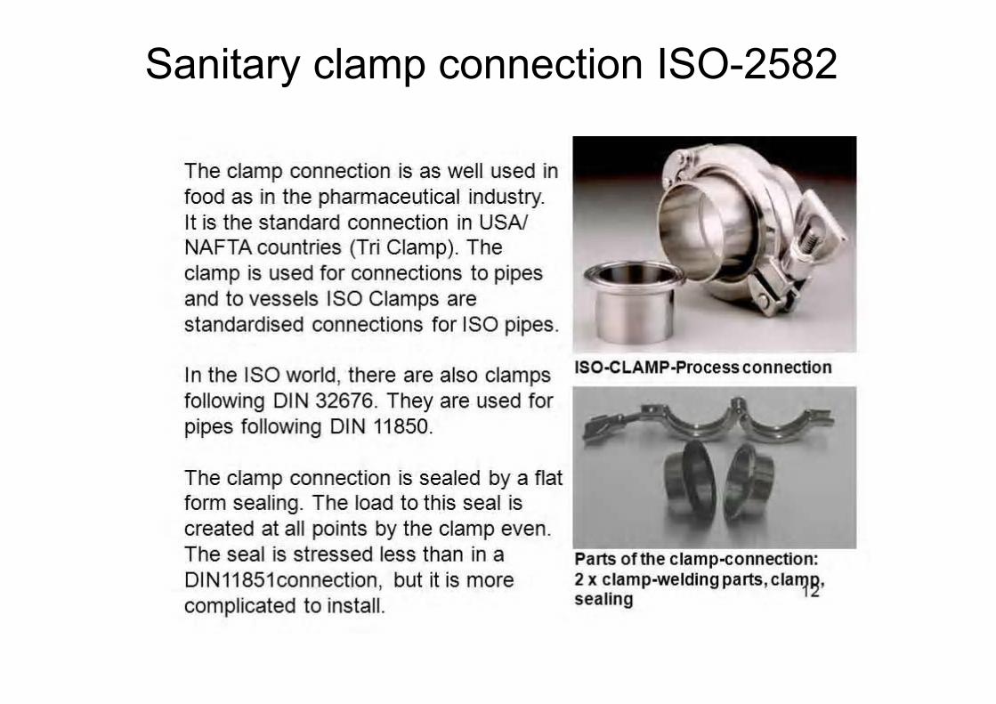
Sanitary clamp connection ISO-2582
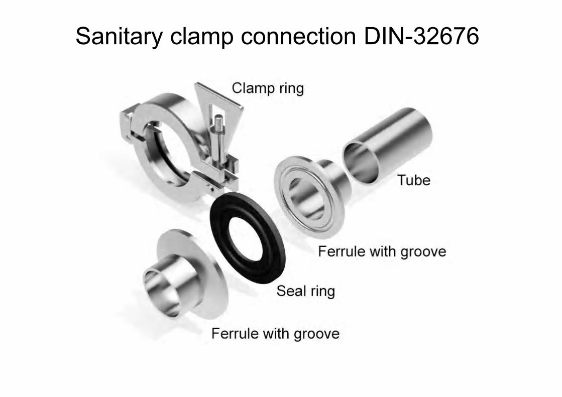
Sanitary clamp connection DIN-32676
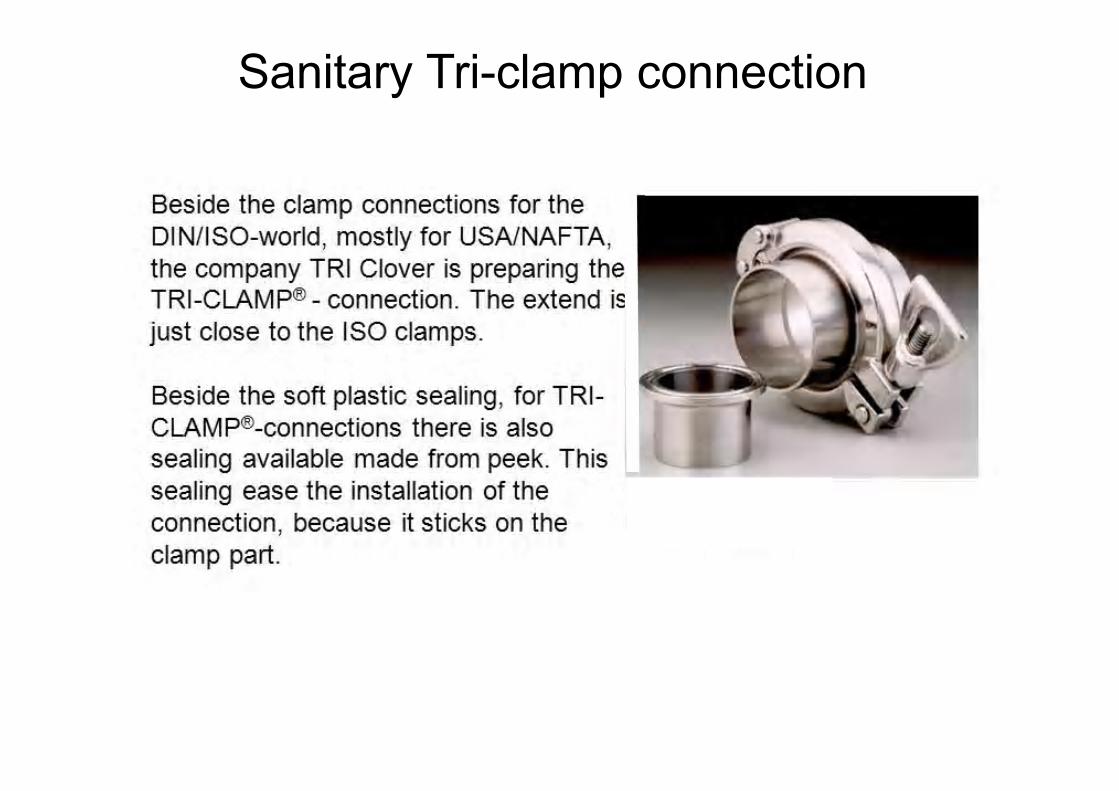
Sanitary Tri-clamp connection
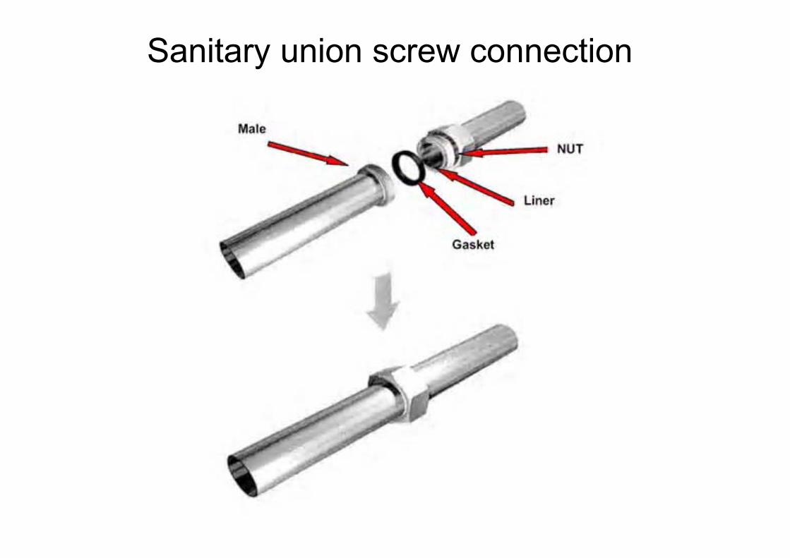
Sanitary union screw connection
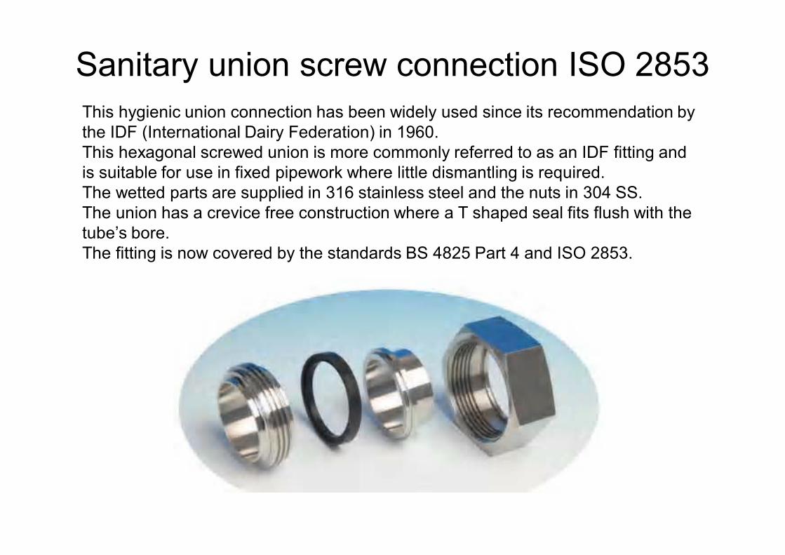
Sanitary union screw connection ISO 2853This hygienic union connection has been widely used since its recommendation by the IDF (International Dairy Federation) in 1960. This hexagonal screwed union is more commonly referred to as an IDF fitting and is suitable for use in fixed pipework where little dismantling is required. The wetted parts are supplied in 316 stainless steel and the nuts in 304 SS. The union has a crevice free construction where a T shaped seal fits flush with the tube’s bore. The fitting is now covered by the standards BS 4825 Part 4 and ISO 2853.
52
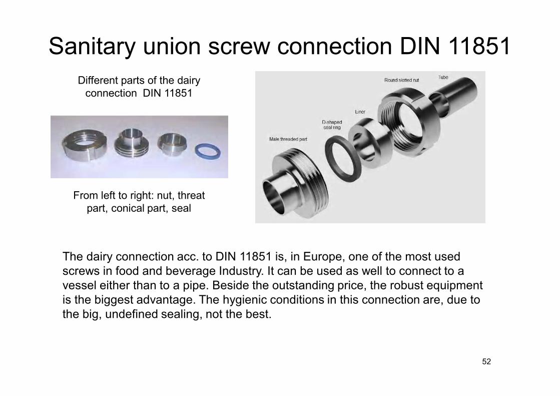
The dairy connection acc. to DIN 11851 is, in Europe, one of the most used screws in food and beverage Industry. It can be used as well to connect to a vessel either than to a pipe. Beside the outstanding price, the robust equipment is the biggest advantage. The hygienic conditions in this connection are, due to the big, undefined sealing, not the best.
Different parts of the dairy connection DIN 11851
From left to right: nut, threat part, conical part, seal
Sanitary union screw connection DIN 11851
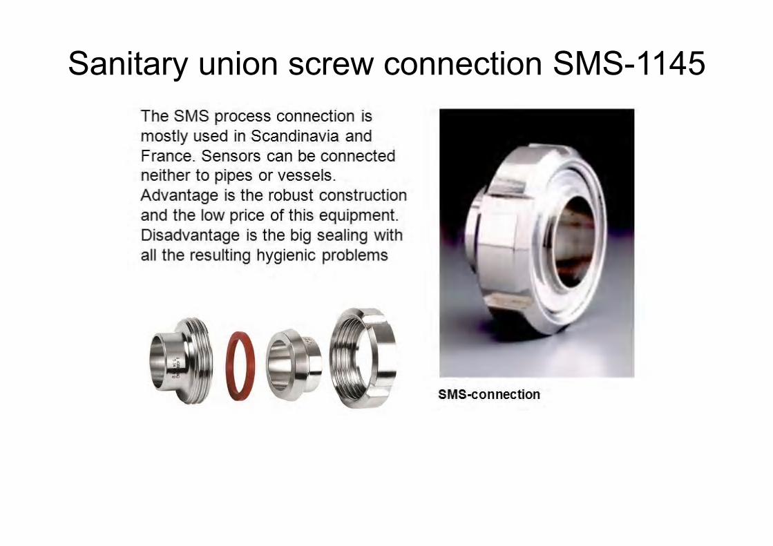
Sanitary union screw connection SMS-1145
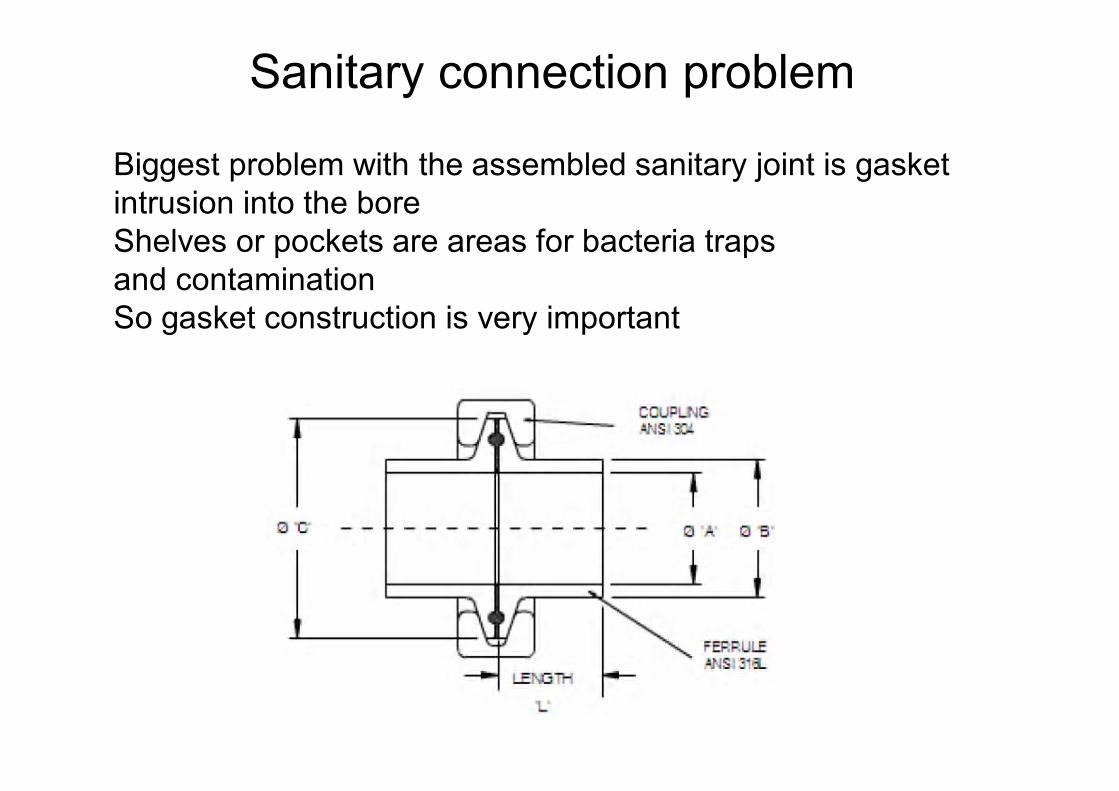
Biggest problem with the assembled sanitary joint is gasket intrusion into the boreShelves or pockets are areas for bacteria trapsand contaminationSo gasket construction is very important
Sanitary connection problem
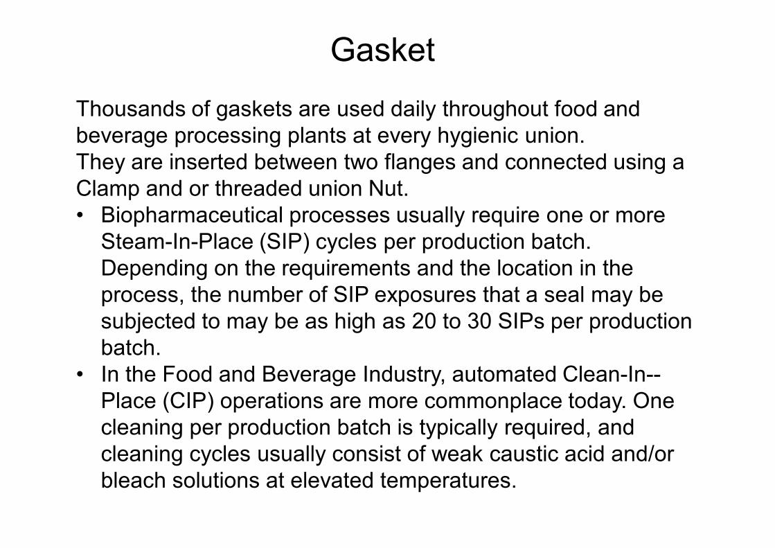
Thousands of gaskets are used daily throughout food and beverage processing plants at every hygienic union. They are inserted between two flanges and connected using a Clamp and or threaded union Nut. • Biopharmaceutical processes usually require one or more
Steam-In-Place (SIP) cycles per production batch. Depending on the requirements and the location in the process, the number of SIP exposures that a seal may be subjected to may be as high as 20 to 30 SIPs per production batch.
• In the Food and Beverage Industry, automated Clean-In--Place (CIP) operations are more commonplace today. One cleaning per production batch is typically required, and cleaning cycles usually consist of weak caustic acid and/or bleach solutions at elevated temperatures.
Gasket
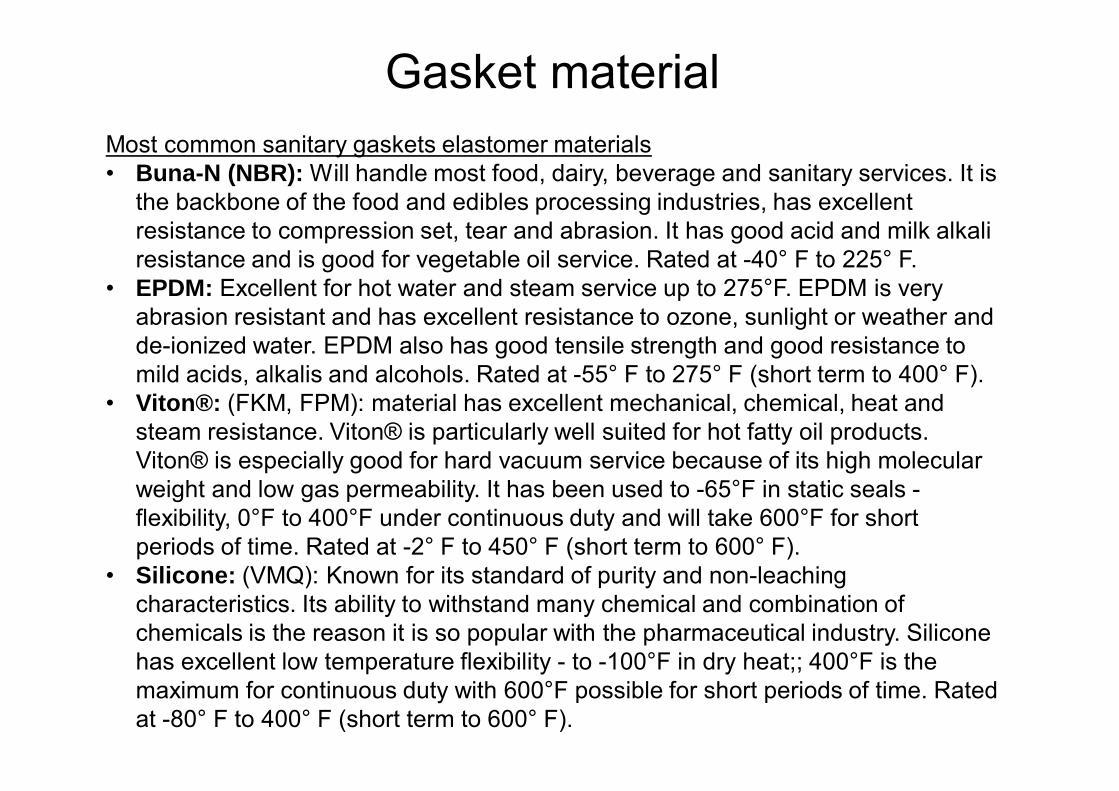
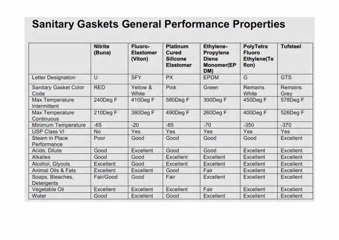
Most common sanitary gaskets elastomer materials• Buna-N (NBR): Will handle most food, dairy, beverage and sanitary services. It is
the backbone of the food and edibles processing industries, has excellent resistance to compression set, tear and abrasion. It has good acid and milk alkali resistance and is good for vegetable oil service. Rated at -40° F to 225° F.
• EPDM: Excellent for hot water and steam service up to 275°F. EPDM is very abrasion resistant and has excellent resistance to ozone, sunlight or weather and de-ionized water. EPDM also has good tensile strength and good resistance to mild acids, alkalis and alcohols. Rated at -55° F to 275° F (short term to 400° F).
• Viton®: (FKM, FPM): material has excellent mechanical, chemical, heat and steam resistance. Viton® is particularly well suited for hot fatty oil products. Viton® is especially good for hard vacuum service because of its high molecular weight and low gas permeability. It has been used to -65°F in static seals -flexibility, 0°F to 400°F under continuous duty and will take 600°F for short periods of time. Rated at -2° F to 450° F (short term to 600° F).
• Silicone: (VMQ): Known for its standard of purity and non-leaching characteristics. Its ability to withstand many chemical and combination of chemicals is the reason it is so popular with the pharmaceutical industry. Silicone has excellent low temperature flexibility - to -100°F in dry heat;; 400°F is the maximum for continuous duty with 600°F possible for short periods of time. Rated at -80° F to 400° F (short term to 600° F).
Gasket material
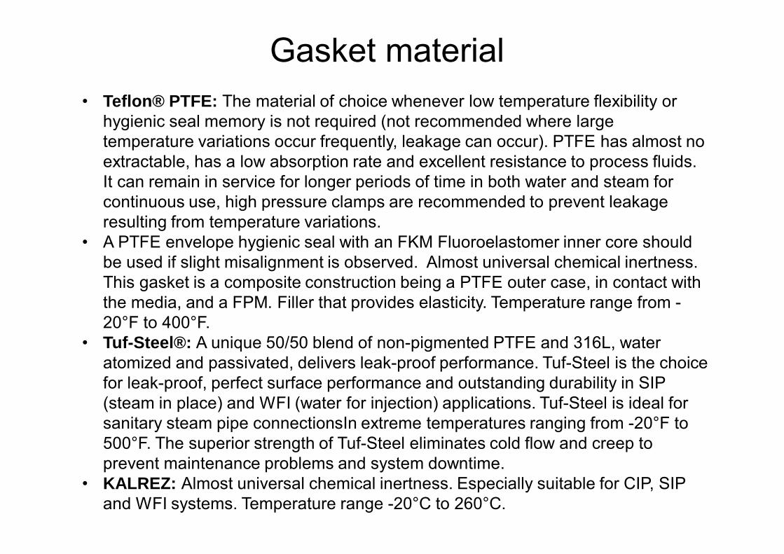
• Teflon® PTFE: The material of choice whenever low temperature flexibility or hygienic seal memory is not required (not recommended where large temperature variations occur frequently, leakage can occur). PTFE has almost no extractable, has a low absorption rate and excellent resistance to process fluids. It can remain in service for longer periods of time in both water and steam for continuous use, high pressure clamps are recommended to prevent leakage resulting from temperature variations.
• A PTFE envelope hygienic seal with an FKM Fluoroelastomer inner core should be used if slight misalignment is observed. Almost universal chemical inertness. This gasket is a composite construction being a PTFE outer case, in contact with the media, and a FPM. Filler that provides elasticity. Temperature range from -20°F to 400°F.
• Tuf-Steel®: A unique 50/50 blend of non-pigmented PTFE and 316L, water atomized and passivated, delivers leak-proof performance. Tuf-Steel is the choice for leak-proof, perfect surface performance and outstanding durability in SIP (steam in place) and WFI (water for injection) applications. Tuf-Steel is ideal for sanitary steam pipe connectionsIn extreme temperatures ranging from -20°F to 500°F. The superior strength of Tuf-Steel eliminates cold flow and creep to prevent maintenance problems and system downtime.
• KALREZ: Almost universal chemical inertness. Especially suitable for CIP, SIP and WFI systems. Temperature range -20°C to 260°C.
Gasket material
Valves are process components that provide dynamic seals within the process.
It is a device that regulates, directs or controls the flow of a fluid (gases, liquids, fluidized solids, or slurries) by opening,
closing, or partially obstructing various passage ways.Valves are technically fittings, but are usually discussed as a
separate category. In an open valve, fluid flows in a direction from higher
pressure to lower pressure. They also provide seals between the process and the
atmosphere. (ASME-BPE, 2014)
Sanitary Valves
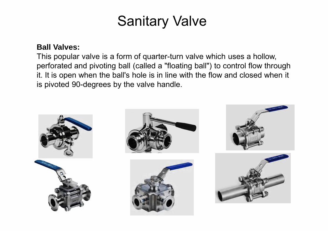
Ball Valves:This popular valve is a form of quarter-turn valve which uses a hollow, perforated and pivoting ball (called a "floating ball") to control flow through it. It is open when the ball's hole is in line with the flow and closed when it is pivoted 90-degrees by the valve handle.
Sanitary Valve
Valves in high purity processes are used in two broad areas of application: 1- Valves that are in direct contact with the final (or intermediate) product 2- Valves that are not in contact with the final (or intermediate) product.
These applications are in “support systems” such as handling clean steam for cleaning and temperature control.
In the pharmaceutical industry ball valves are never used in applications or processes where they may be in direct contact with the final product.
What are the industry criteria for high purity valves? The pharmaceutical industry derives the valve selection criteria from two sources: 1. ASME/BPE (Specifications for Bioprocessing Equipment) 2. FDA material and design specifications
High purity ball valve
ASME/BPE is the evolving specification document that addresses the design and use of equipment for the pharmaceutical industry. • The standard is intended for design, materials, construction, inspection
and testing of vessels, piping and related accessories such as pumps, valves, and fittings for use in the biopharmaceutical industry.
• Essentially the document states, “…all parts that contact either the products, raw materials, or product intermediates during manufacturing, process development, or scale-up...and are a critical part of product manufacture, such as Water-For-Injection (WFI), clean steam, ultrafiltration, intermediate product storage, and centrifuges.”
High purity ball valve
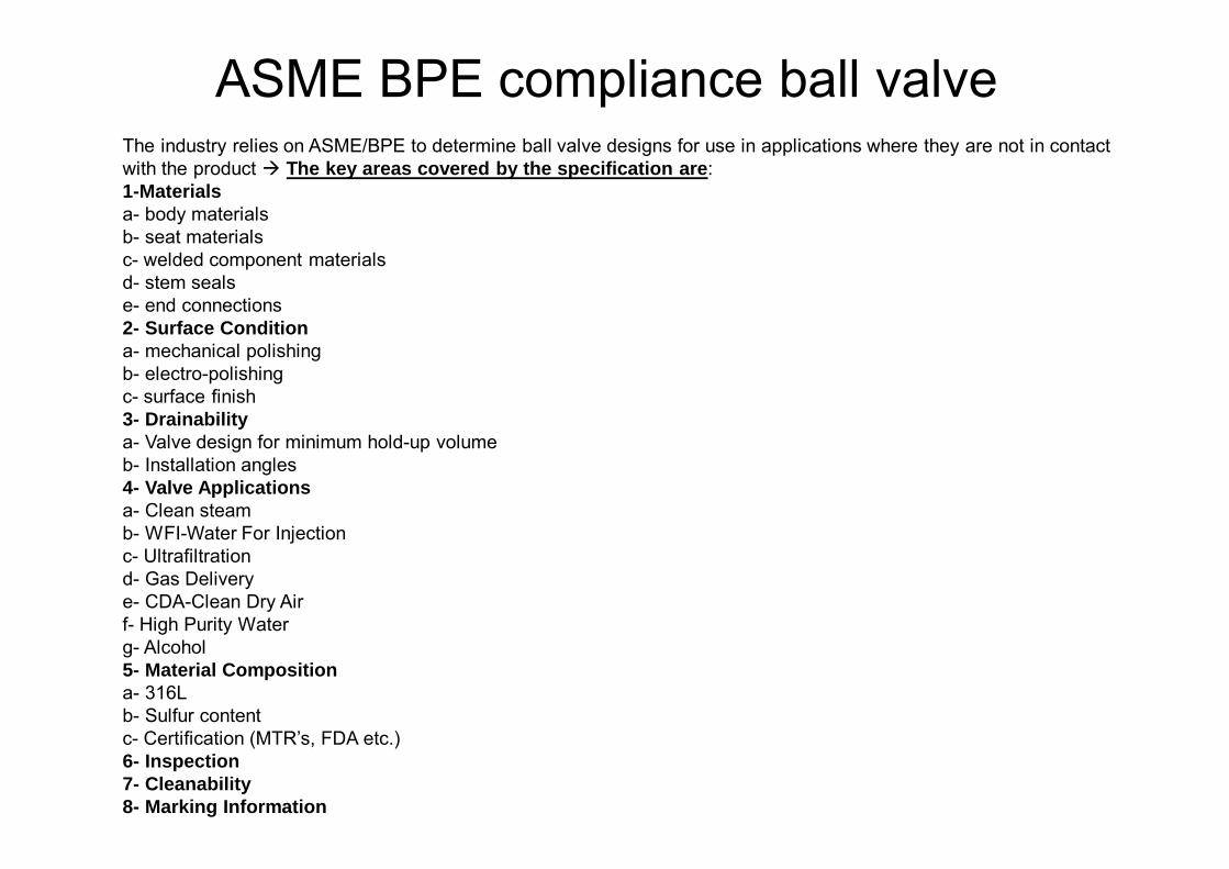
The industry relies on ASME/BPE to determine ball valve designs for use in applications where they are not in contact with the product The key areas covered by the specification are: 1-Materials a- body materials b- seat materials c- welded component materials d- stem seals e- end connections 2- Surface Condition a- mechanical polishing b- electro-polishing c- surface finish 3- Drainabilitya- Valve design for minimum hold-up volume b- Installation angles 4- Valve Applications a- Clean steam b- WFI-Water For Injection c- Ultrafiltration d- Gas Delivery e- CDA-Clean Dry Air f- High Purity Water g- Alcohol 5- Material Composition a- 316L b- Sulfur content c- Certification (MTR’s, FDA etc.) 6- Inspection 7- Cleanability8- Marking Information
ASME BPE compliance ball valve
What is “validation”?Validation is a regulatory procedure that intends to assure repeatability of a processed product or formulation.• The procedure indicates that mechanical process components, formulation, times,
temperatures, pressures and other conditions be measured and monitored. • Once a system and the product of that system have proven repeatable all
components and conditions are deemed validated No changes maybe made to the final “package”(process system andprocedures)without re-validating.
• There is also the related issue of material verification, MTR’s (Material Test Report) is a statement from casting producers that documents the composition of the casting and verifies that it has come from a specific run in the casting process.
• This degree of traceability is desirable in all critical piping component installations in many industries. All valves supplied for pharmaceutical applications must be accompanied by MTR’s.
• Seat material manufacturers provide a composition report to ensure that valve seats meet FDA guidelines. (FDA/USP Class VI) Acceptable seat materials include PTFE, RTFE, Kel-F and TFM.
Validation

What fluids are typically handled by high purity ball valves? Due to the inherent flexibility of the ball valve design, it is readily available in a wide range of seats, seals and body materials. As a result, ball valves are produced to handle fluids such as:
• Steam – process temperature control / cleaning
• High Purity Water – cleaning
• High Purity Gas – purging
• CDA (Clean Dry Air) – purging
• Alcohol – deliver alcohol to final product (cosmetics) / cleaning
High purity ball valve

When are valves selected with ETO or Tri-Clamp end connections? What other ends are used? • Whenever possible, the bio-pharm industry prefers to install “sealed systems”.
Extended Tube OD (ETO) connections are welded in-line to eliminate contamination from outside the valve/piping boundary and to add rigidity to the piping system.
• Tri-Clamp (Hygienic Clamp Connections) ends add flexibility to the system and may be installed without welding ith Tri-Clamp ends, piping systems may be disassembled and re-configured more readily.
ETO or Tri-Clamp
Sanitary ball valve with Tri-clamp connection
Sanitary ball valve with ETO connection
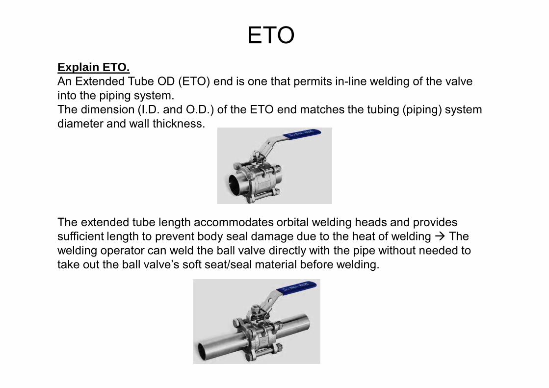
Explain ETO. An Extended Tube OD (ETO) end is one that permits in-line welding of the valve into the piping system. The dimension (I.D. and O.D.) of the ETO end matches the tubing (piping) system diameter and wall thickness.
The extended tube length accommodates orbital welding heads and provides sufficient length to prevent body seal damage due to the heat of welding The welding operator can weld the ball valve directly with the pipe without needed to take out the ball valve’s soft seat/seal material before welding.
ETO
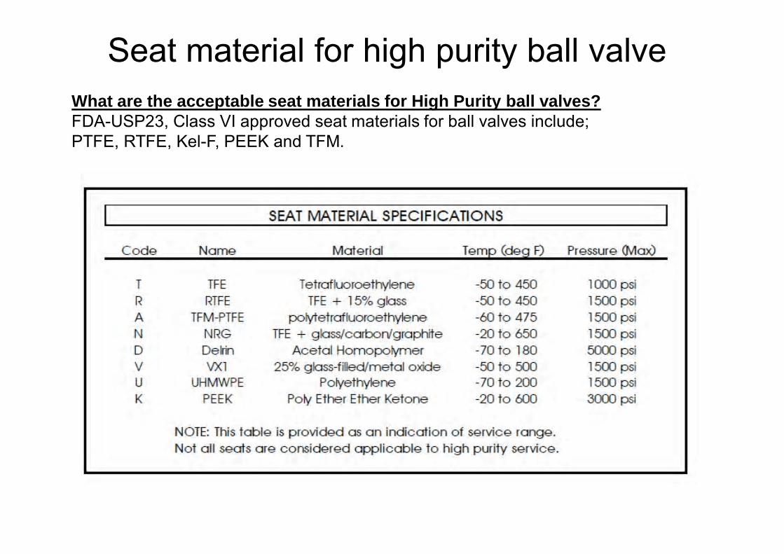
What are the acceptable seat materials for High Purity ball valves? FDA-USP23, Class VI approved seat materials for ball valves include; PTFE, RTFE, Kel-F, PEEK and TFM.
Seat material for high purity ball valve
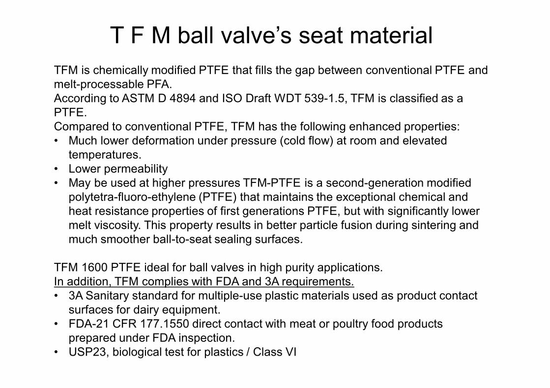
TFM is chemically modified PTFE that fills the gap between conventional PTFE and melt-processable PFA. According to ASTM D 4894 and ISO Draft WDT 539-1.5, TFM is classified as a PTFE. Compared to conventional PTFE, TFM has the following enhanced properties: • Much lower deformation under pressure (cold flow) at room and elevated
temperatures. • Lower permeability • May be used at higher pressures TFM-PTFE is a second-generation modified
polytetra-fluoro-ethylene (PTFE) that maintains the exceptional chemical and heat resistance properties of first generations PTFE, but with significantly lower melt viscosity. This property results in better particle fusion during sintering and much smoother ball-to-seat sealing surfaces.
TFM 1600 PTFE ideal for ball valves in high purity applications. In addition, TFM complies with FDA and 3A requirements. • 3A Sanitary standard for multiple-use plastic materials used as product contact
surfaces for dairy equipment. • FDA-21 CFR 177.1550 direct contact with meat or poultry food products
prepared under FDA inspection. • USP23, biological test for plastics / Class VI
T F M ball valve’s seat material
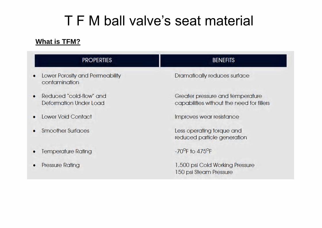
What is TFM?
T F M ball valve’s seat material
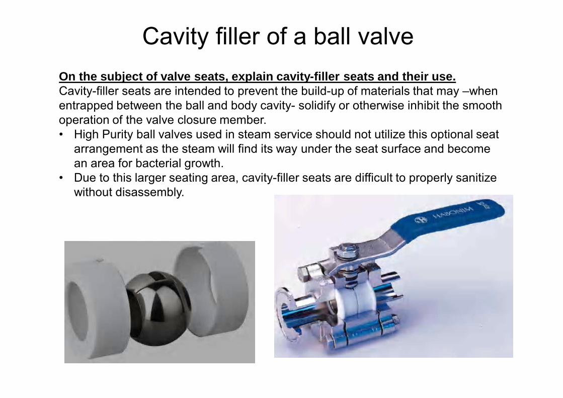
On the subject of valve seats, explain cavity-filler seats and their use. Cavity-filler seats are intended to prevent the build-up of materials that may –when entrapped between the ball and body cavity- solidify or otherwise inhibit the smooth operation of the valve closure member. • High Purity ball valves used in steam service should not utilize this optional seat
arrangement as the steam will find its way under the seat surface and become an area for bacterial growth.
• Due to this larger seating area, cavity-filler seats are difficult to properly sanitize without disassembly.
Cavity filler of a ball valve
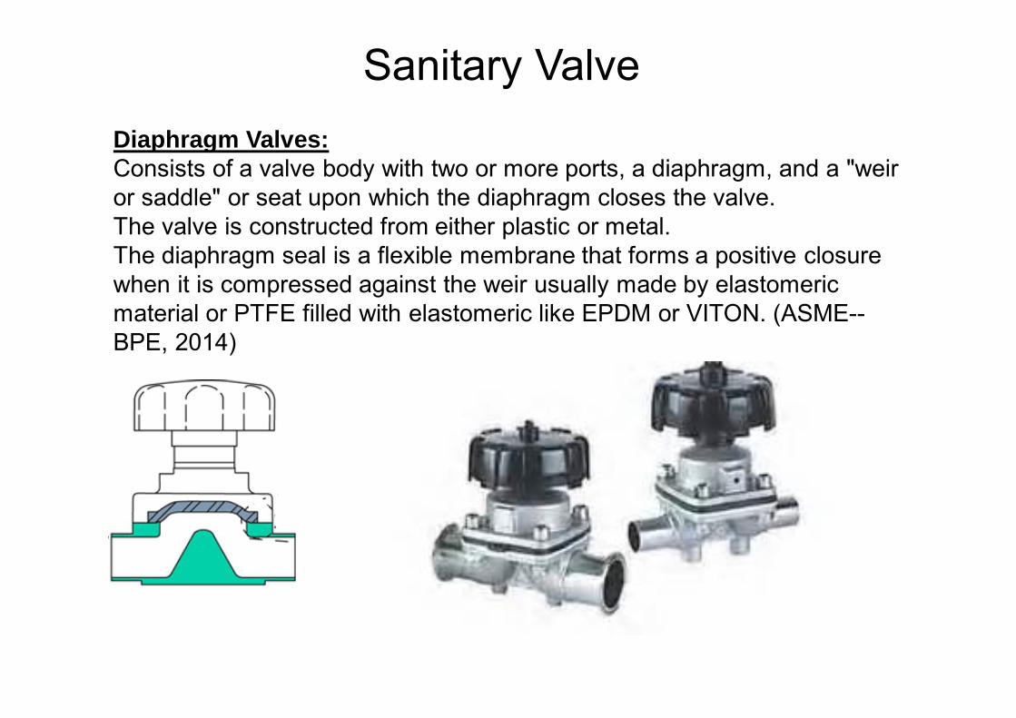
Diaphragm Valves:Consists of a valve body with two or more ports, a diaphragm, and a "weir or saddle" or seat upon which the diaphragm closes the valve. The valve is constructed from either plastic or metal.The diaphragm seal is a flexible membrane that forms a positive closure when it is compressed against the weir usually made by elastomeric material or PTFE filled with elastomeric like EPDM or VITON. (ASME--BPE, 2014)
Sanitary Valve
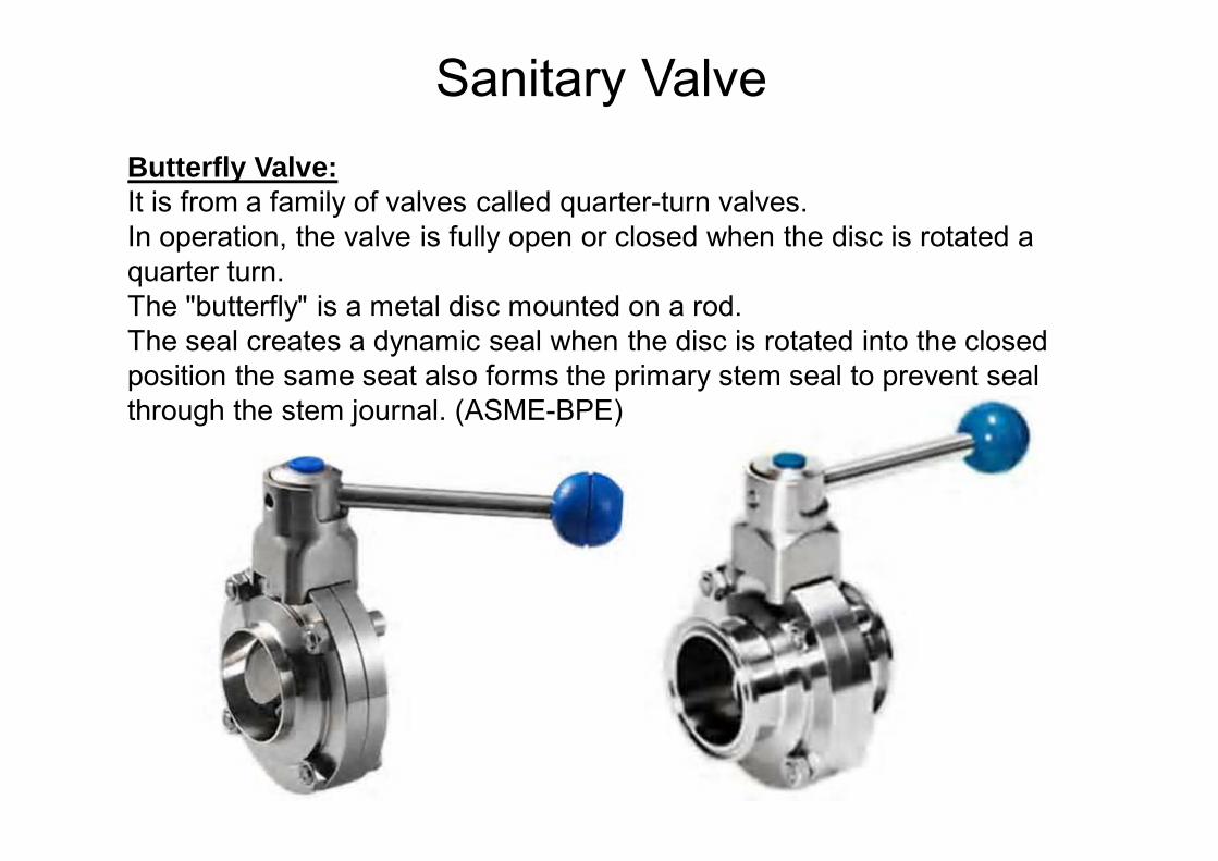
Butterfly Valve:It is from a family of valves called quarter-turn valves. In operation, the valve is fully open or closed when the disc is rotated a quarter turn. The "butterfly" is a metal disc mounted on a rod. The seal creates a dynamic seal when the disc is rotated into the closed position the same seat also forms the primary stem seal to prevent seal through the stem journal. (ASME-BPE)
Sanitary Valve
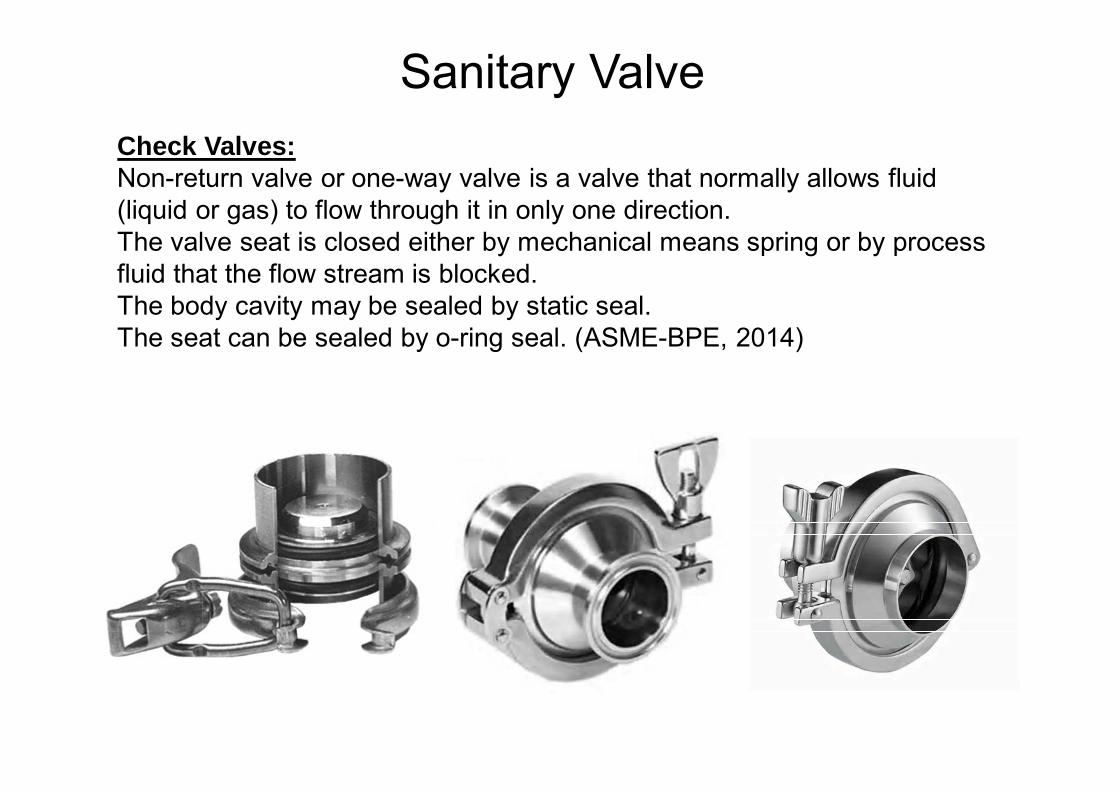
Check Valves:Non-return valve or one-way valve is a valve that normally allows fluid (liquid or gas) to flow through it in only one direction. The valve seat is closed either by mechanical means spring or by processfluid that the flow stream is blocked. The body cavity may be sealed by static seal.The seat can be sealed by o-ring seal. (ASME-BPE, 2014)
Sanitary Valve
Sanitary Valve
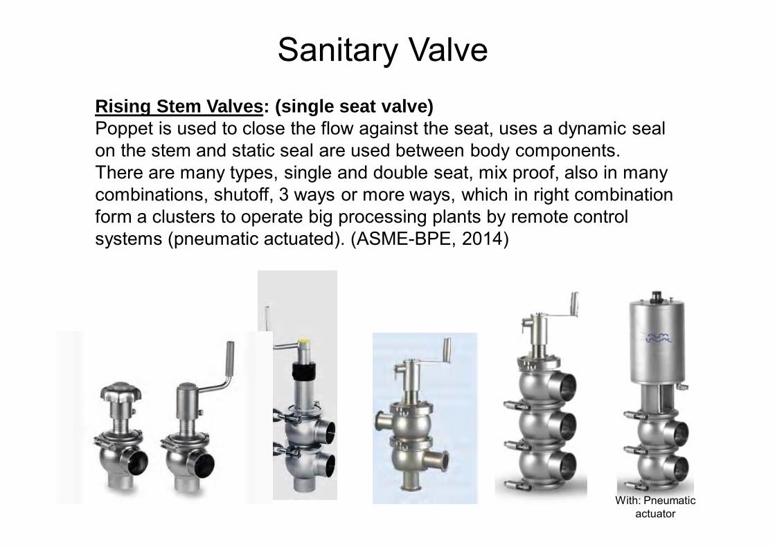
Rising Stem Valves: (single seat valve)Poppet is used to close the flow against the seat, uses a dynamic seal on the stem and static seal are used between body components. There are many types, single and double seat, mix proof, also in many combinations, shutoff, 3 ways or more ways, which in right combination form a clusters to operate big processing plants by remote control systems (pneumatic actuated). (ASME-BPE, 2014)
Sanitary Valve
With: Pneumatic actuator

Relief valve:The relief valve (RV) is a type of valve used to control or limit the pressure in a system or vessel which can build up for a process upset, instrument orequipment failure. • Vacuum safety valves (or combined pressure/vacuum safety valves) are used to
prevent a tank from collapsing while it is being emptied, or when cold rinse water is used after hot CIP (clean-in-place) or SIP (sterilization-in-place) procedures.
• When sizing a vacuum safety valve, the calculation method is not defined in any norm, particularly in the hot CIP / cold water scenario, but some manufacturers have developed sizing simulations
Sanitary Valve
Pressure-Vacuum relief valve Air relief valve Safety relief valve
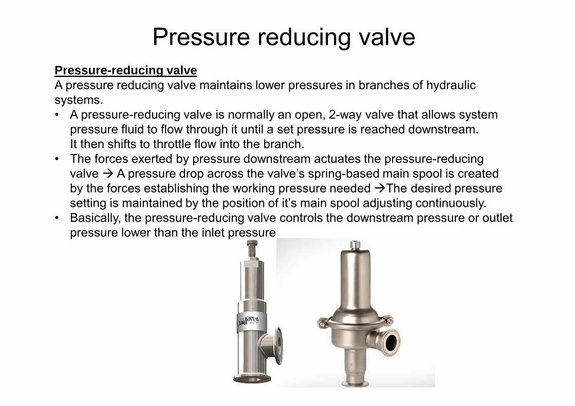
Pressure reducing valvePressure-reducing valveA pressure reducing valve maintains lower pressures in branches of hydraulic systems. • A pressure-reducing valve is normally an open, 2-way valve that allows system
pressure fluid to flow through it until a set pressure is reached downstream. It then shifts to throttle flow into the branch.
• The forces exerted by pressure downstream actuates the pressure-reducing valve A pressure drop across the valve’s spring-based main spool is created by the forces establishing the working pressure needed The desired pressure setting is maintained by the position of it’s main spool adjusting continuously.
• Basically, the pressure-reducing valve controls the downstream pressure or outlet pressure lower than the inlet pressure
Accessories
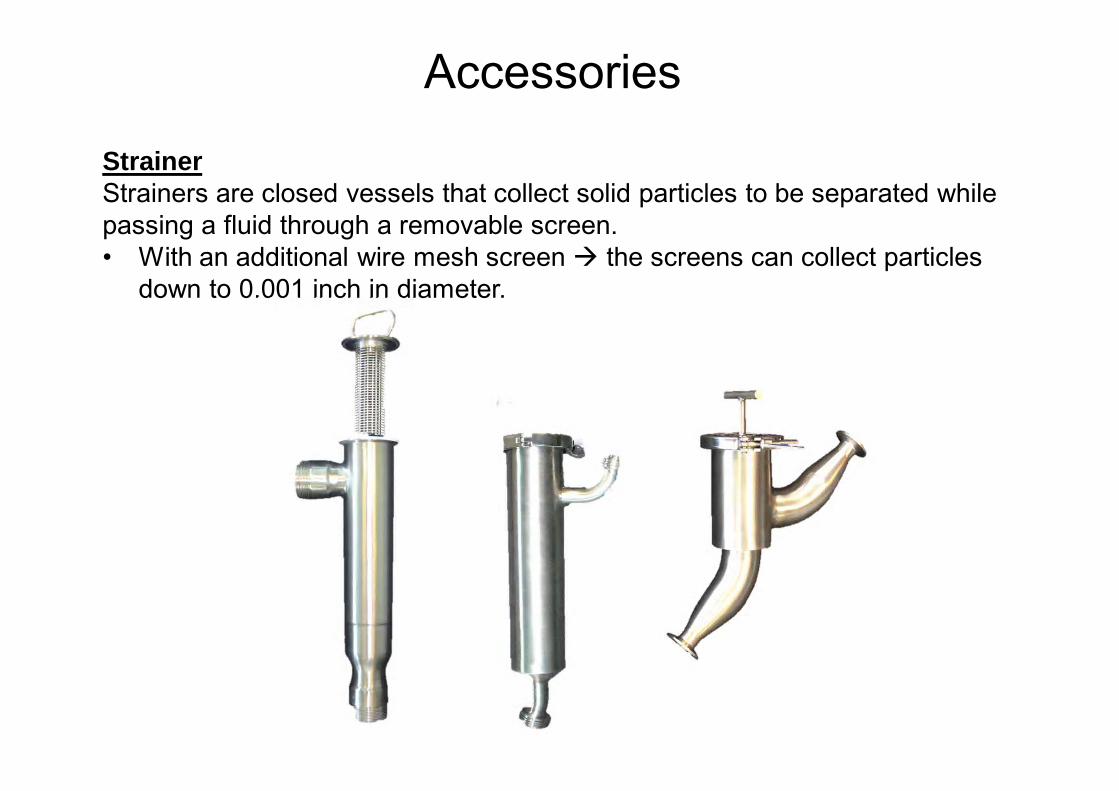
StrainerStrainers are closed vessels that collect solid particles to be separated while passing a fluid through a removable screen. • With an additional wire mesh screen the screens can collect particles
down to 0.001 inch in diameter.
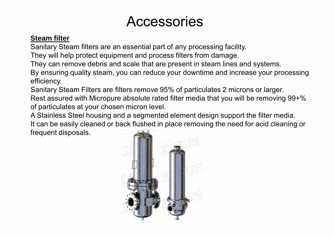
AccessoriesSteam filterSanitary Steam filters are an essential part of any processing facility. They will help protect equipment and process filters from damage. They can remove debris and scale that are present in steam lines and systems. By ensuring quality steam, you can reduce your downtime and increase your processing efficiency.Sanitary Steam Filters are filters remove 95% of particulates 2 microns or larger. Rest assured with Micropure absolute rated filter media that you will be removing 99+% of particulates at your chosen micron level. A Stainless Steel housing and a segmented element design support the filter media. It can be easily cleaned or back flushed in place removing the need for acid cleaning or frequent disposals.
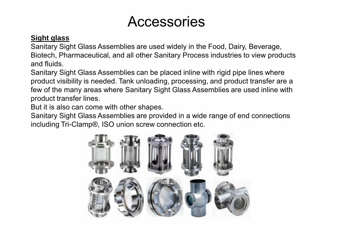
AccessoriesSight glassSanitary Sight Glass Assemblies are used widely in the Food, Dairy, Beverage, Biotech, Pharmaceutical, and all other Sanitary Process industries to view products and fluids. Sanitary Sight Glass Assemblies can be placed inline with rigid pipe lines where product visibility is needed. Tank unloading, processing, and product transfer are a few of the many areas where Sanitary Sight Glass Assemblies are used inline with product transfer lines. But it is also can come with other shapes.Sanitary Sight Glass Assemblies are provided in a wide range of end connections including Tri-Clamp®, ISO union screw connection etc.
• Pressure-containing components are marked with heat numbers and backed by appropriate analysis certificates.
• Mill Test Reports (MTR’s) are recorded for each size and heat number.• These documents include some or all of the following:
a- Alloy- ASTM designation b- Heat number c- Year and month of manufacture d- Chemical analysis e- Mechanical properties f- Heat treatment
Certificate of tracebility
Material ReceptionCheck the following points carefully when the material arrives:• Material has been delivered in the agreed quality, and make sure
mill certificates numbers match with heat numbers engrave on pipes and fittings.
• Fittings and pipes are wrapped according with the specifications.• Longitudinal welding in pipes and fittings not show any
discoloration on the inside.
Material receiving & inspection
Deep Material Inspection AnalysisDepend on the Installation requirements there is some additional analysis might be done Rx Gun Spectrometric material analysis you might get detailed metallic material composition except carbon content Roughness micro meters to verify inside and/or outside material roughness according with surface profiles.• Measure tools instruments to verify fittings and tubing dimensions.• After receiving inspection has finished would be a good practice make
a report for the material traceabillity installation records, or simply to make any claim to the suppliers
Material receiving & inspection
Material StorageOnce the receiving inspection has being completed, pipes and fittings must be resealed to avoid impurities and/or small insects come in to the pipe and fittings. All materials(Sheets, Pipes, Valves and Fittings) must be stored in a dry, dust free room (Folkmar Andersen & A/S, 2006
Material receiving & inspection
GeneralFor every project must be defined a welding specification describing requirements for welding procedure, control and inspection of the finished job. • If the delivered job ”fails” at the inspection, and/or does not meet the
specified quality requirements, the inspection should be intensified beyond what was agreed. All defects found must be repaired.
• Welding of product pipes must only be carried out by certified welders.
Welding RoughnessThe normal roughness of a well-performed weld will be approx. 1.6 to 4 μm. The maximum roughness accepted on the product side is 6 μm.
ShieldingDuring stainless steel welding, shielding gas must be used at all the times, both on the front and on the backside of the weld zone. The purpose of the shielding gas is to prevent the access of oxygen to the weld area insufficient shielding will become in oxidation of the heat-affected weld zone. This will reduce stainless chemical properties.Often, argon is used in the welding gun and as gas protection inside pipes..
Welding
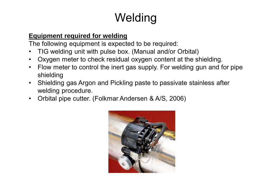
Equipment required for weldingThe following equipment is expected to be required:• TIG welding unit with pulse box. (Manual and/or Orbital)• Oxygen meter to check residual oxygen content at the shielding.• Flow meter to control the inert gas supply. For welding gun and for pipe
shielding• Shielding gas Argon and Pickling paste to passivate stainless after
welding procedure.• Orbital pipe cutter. (Folkmar Andersen & A/S, 2006)
Welding
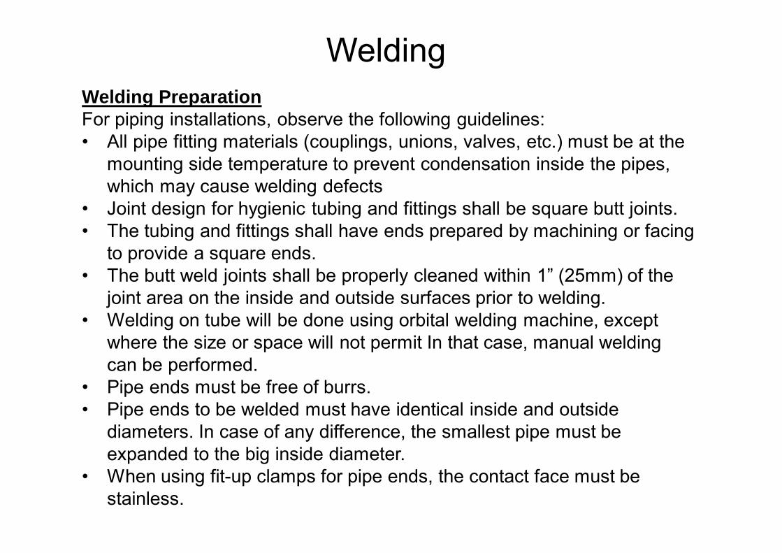
Welding PreparationFor piping installations, observe the following guidelines:• All pipe fitting materials (couplings, unions, valves, etc.) must be at the
mounting side temperature to prevent condensation inside the pipes, which may cause welding defects
• Joint design for hygienic tubing and fittings shall be square butt joints.• The tubing and fittings shall have ends prepared by machining or facing
to provide a square ends. • The butt weld joints shall be properly cleaned within 1” (25mm) of the
joint area on the inside and outside surfaces prior to welding.• Welding on tube will be done using orbital welding machine, except
where the size or space will not permit In that case, manual welding can be performed.
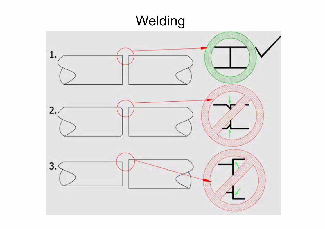
• Pipe ends must be free of burrs.• Pipe ends to be welded must have identical inside and outside
diameters. In case of any difference, the smallest pipe must be expanded to the big inside diameter.
• When using fit-up clamps for pipe ends, the contact face must be stainless.
Welding
Welding
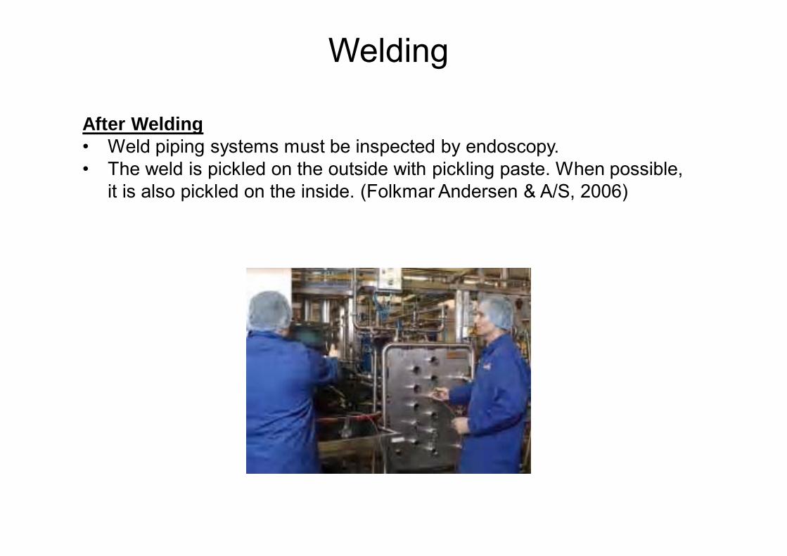
After Welding• Weld piping systems must be inspected by endoscopy.• The weld is pickled on the outside with pickling paste. When possible,
it is also pickled on the inside. (Folkmar Andersen & A/S, 2006)
Welding
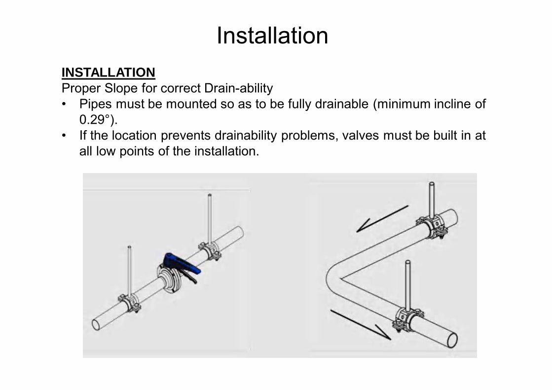
INSTALLATIONProper Slope for correct Drain-ability• Pipes must be mounted so as to be fully drainable (minimum incline of
0.29°).• If the location prevents drainability problems, valves must be built in at
all low points of the installation.
Installation
Installation
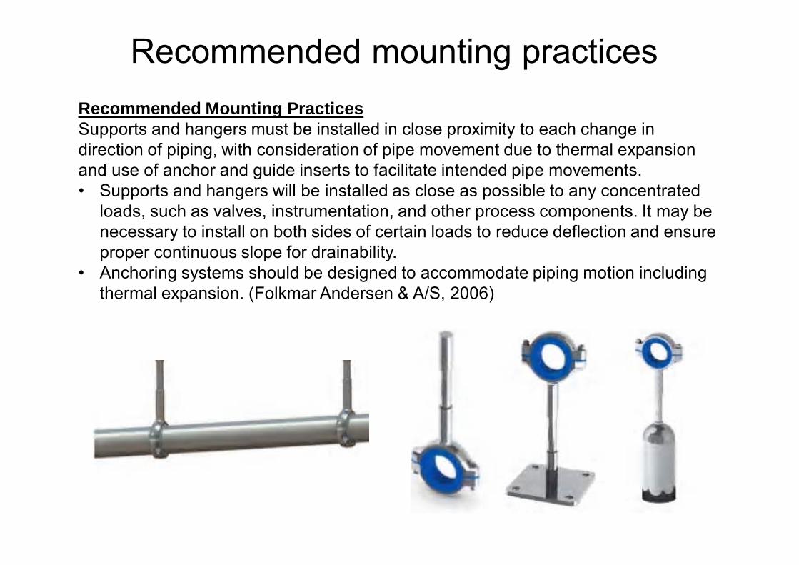
Recommended Mounting PracticesSupports and hangers must be installed in close proximity to each change in direction of piping, with consideration of pipe movement due to thermal expansion and use of anchor and guide inserts to facilitate intended pipe movements.• Supports and hangers will be installed as close as possible to any concentrated
loads, such as valves, instrumentation, and other process components. It may be necessary to install on both sides of certain loads to reduce deflection and ensure proper continuous slope for drainability.
• Anchoring systems should be designed to accommodate piping motion including thermal expansion. (Folkmar Andersen & A/S, 2006)
Recommended mounting practices
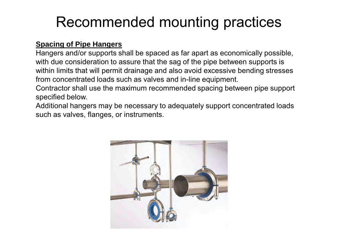
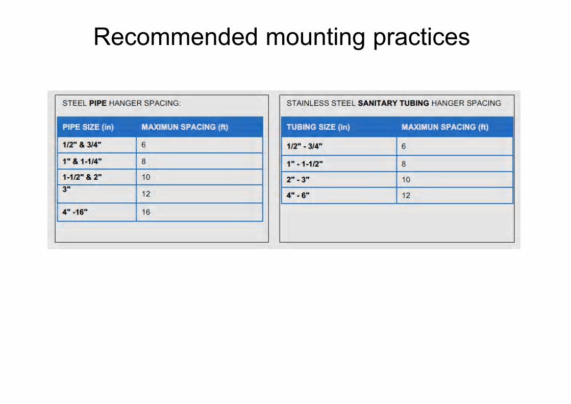
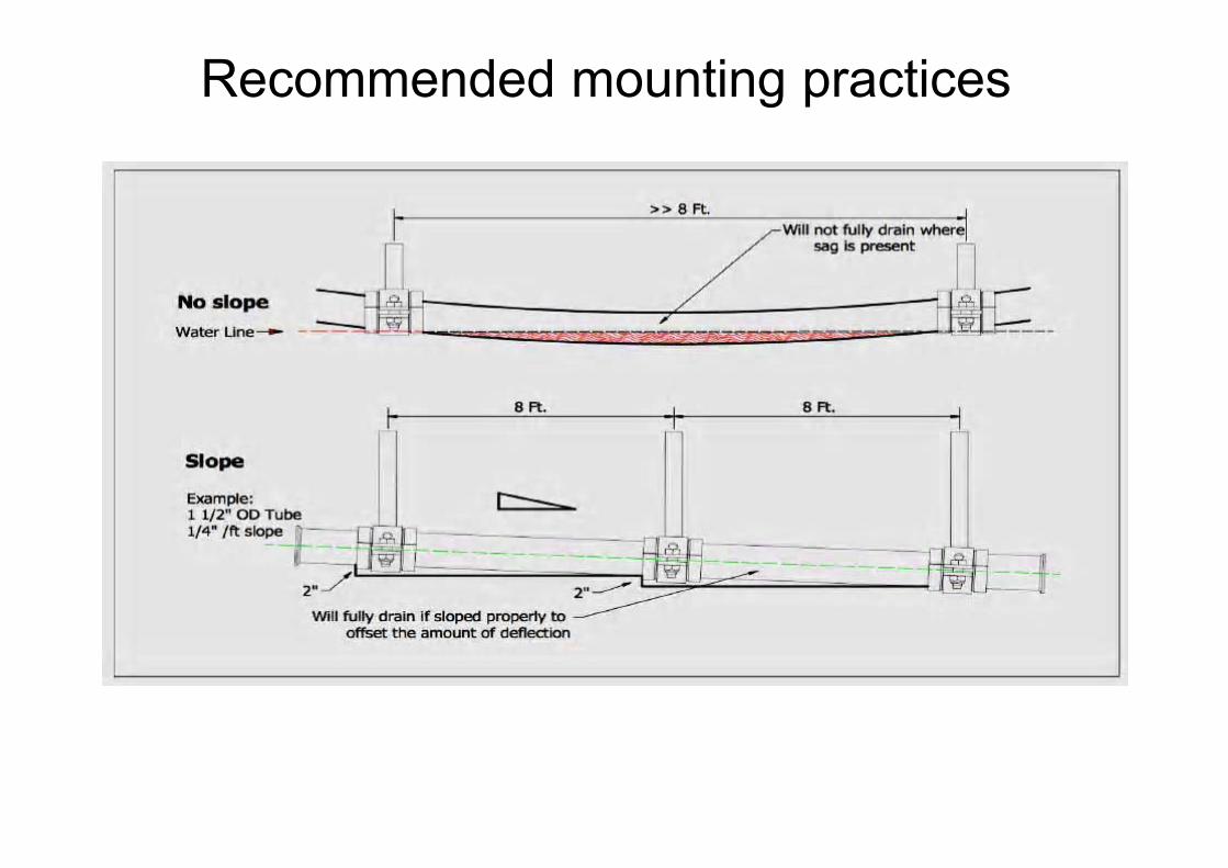
Spacing of Pipe HangersHangers and/or supports shall be spaced as far apart as economically possible, with due consideration to assure that the sag of the pipe between supports is within limits that will permit drainage and also avoid excessive bending stresses from concentrated loads such as valves and in-line equipment.Contractor shall use the maximum recommended spacing between pipe support specified below.Additional hangers may be necessary to adequately support concentrated loads such as valves, flanges, or instruments.
Recommended mounting practices
Recommended mounting practices
Recommended mounting practices
Welding Inspection1. Verify all welding test and reports approved by Quality Assurance team
from welders who carry out welding operations during installation.2. A minimum of 5 per cent of all pipe welds must be endoscopied welds
must subsequently be individually identifiable and recorded.3. If defects are detected, an extended endoscopy inspection is made on
10 of the welder’s latest welds. If further defects are found, the welder in question must have his certificate renewed. Before the welder can perform welding operations on installations again, he must perform three supervised, error-free welds on setups selected by Quality Assurance Team.
4. If defects are detected during 2.-, further endoscopy inspection must be carried out on 5 per cent of the other welds that were not referred to under 3.-.
5. Endoscopy must be carried out regularly – weekly – and video copy hereof must be sent to Quality Assurance Team, as the inspections are performed.
6. The customer reserves the right to carry out his own endoscopy to an extent chosen by him, and documented defects must be subject to the procedures in steps 2.
Installation inspection

Pipe work InspectionThe layout of the mounted pipe runs is sensible and according to the projectspecifications. the selected pipe dimensions, valves and other equipment are sensible to mounting requirements and guidelines have been observed.• If a plant inspection shows inside discolorations from welding, and there
is no root defect in the welds, the discolorations can be removed by pickling. The pickling procedure must ensure:
• Rubber gaskets, pumps mechanical seals and similar materials are not damaged
• Pickling does not represent any kind of danger or hazard to persons and the environment
• No valves and measurement equipment is damaged• The pickling procedure must be approved by the customer and his safety
representative before it can be implemented! (Folkmar Andersen & A/S, 2006)
Installation inspection
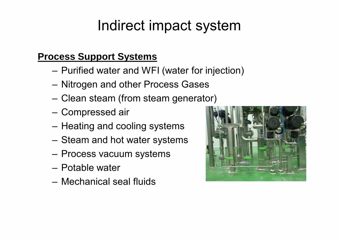
Process Support Systems – Purified water and WFI (water for injection)– Nitrogen and other Process Gases– Clean steam (from steam generator)– Compressed air– Heating and cooling systems– Steam and hot water systems– Process vacuum systems– Potable water– Mechanical seal fluids
Indirect impact system
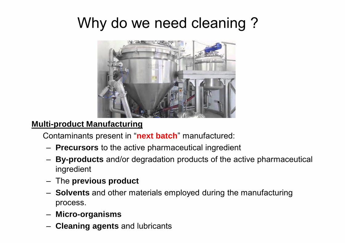
Multi-product ManufacturingContaminants present in “next batch” manufactured:– Precursors to the active pharmaceutical ingredient– By-products and/or degradation products of the active pharmaceutical
ingredient– The previous product– Solvents and other materials employed during the manufacturing
process.– Micro-organisms– Cleaning agents and lubricants
Why do we need cleaning ?

• In-line sterilization of processing equipment
• Clean in place/Steam in place (CIP/SIP)
– A way to clean processing equipment without moving them or taking them apart using a high-pressure rinsing treatment and is sometimes followed by SIP sanitization (tanks, piping, valves etc.)
How we do cleaning
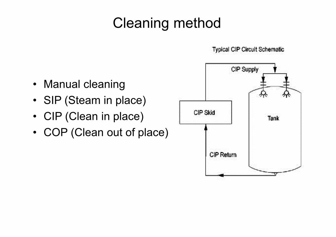
• Manual cleaning• SIP (Steam in place)• CIP (Clean in place)• COP (Clean out of place)
Cleaning method
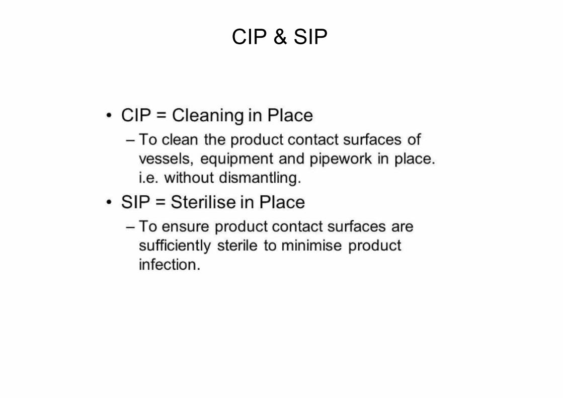
CIP & SIP
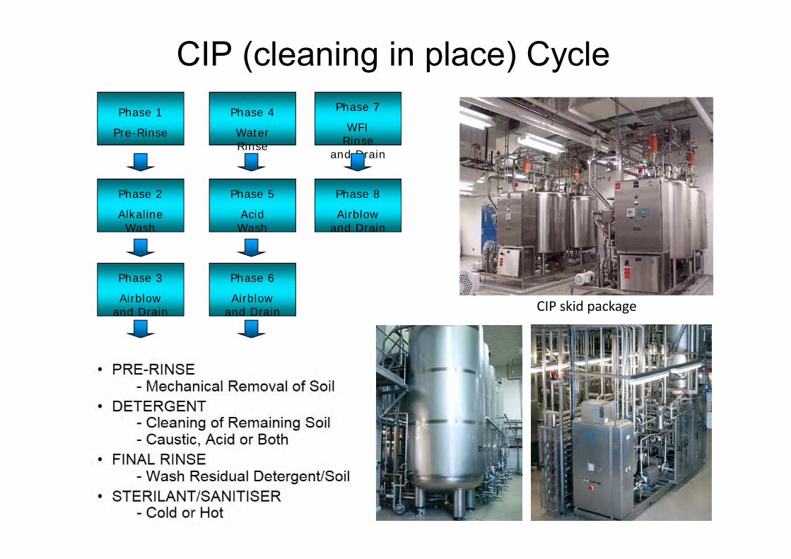
Phase 1
Pre-Rinse
Phase 2
Alkaline Wash
Phase 3
Airblow and Drain
Phase 4
Water Rinse
Phase 5
Acid Wash
Phase 6
Airblow and Drain
Phase 7
WFI Rinse
and Drain
Phase 8
Airblow and Drain
CIP (cleaning in place) Cycle
CIP skid package
• 4 factors that affect efficiency of CIP:– Cleaning Solution Temperature– Cleaning Solution concentration– Cleaning Solution contact time– Velocity and pressure (turbulence)
• Capacity Gains– Reduce cycle time by 50%– Increase production runs– Reduction of water usage– Cleaning agent usage– Plant operating costs
CIP capacity gains

SIP (steam in place) is a timed sterilization of the upstream & downstream biopharmaceutical production train with clean steam. It is part of the 5 step sanitation routine that occurs after every production batch and follows the final rinse (CIP).Every square cm of all process piping & vessels that come in direct or indirect contact with process input, process & process output is sterilized to insure that there is no microbiological activity in the system.Clean steam is circulated through all the process tubing during this stage and enters large vessels through spray balls (engineering nozzle) imbedded in the vessel ceiling.
Cleaning method