Embed Size (px)
Citation preview
Computer Architecture II
Author: Jose 胡冠洲 @ ShanghaiTech
Computer Architecture IITechnical Paper Writing StreamlineWeekly Reading Reports
Technical Paper Writing Streamline
Note Link
Weekly Reading Reports
See below.
Computer Architecture II: Reading Report 1Guanzhou Hu
Computer Science and TechnologyShanghaiTech University
Abstract—This report is a brief summary of the paper “Archi-tecture of the IBM System/360” [1], which presents the ground-breaking contributions in general-purpose utility and inter-modelcompatibility of the IBM S/360∗ system.
I. INTRODUCTION
Computer systems are designed to serve dedicated applica-tions upon specific hardware models in 1950s. [2] As a bigstep of innovation, the birth of the IBM System/360 in 1964marks the first appearance of a truly general-purpose computersystem and the creation of computer family concept. Thearchitectural structure of the IBM S/360 system is proposedin accordance with two major criteria:
• It must be general-purpose. It should be able to serve dif-ferent scientific, real-time and commercial applications.
• It must achieve compatibility among the six sub-modelswith different scales in the same S/360 family.
Section below summarizes the key objectives of S/360guided by the above two criteria. Detailed design principlesand corresponding trade-offs encountered during its develop-ment are covered in the next section.
II. KEY OBJECTIVES
This section extracts four key objectives of the IBM S/360system, which lead the overall design and implementation ofthe system.
1) The system must be a versatile platform for users, inorder to support different types of applications.
2) The system must separate its logical structure withthe physical machine resources to achieve compatibilityamong machine models of different sizes.
3) The system should be designed as an open-ended frame-work, which allows future integration with new softwareand hardware technologies.
4) When the above three requirements are all satisfied, themost efficient design (“efficient” means higher perfor-mance with the same cost) should be adopted.
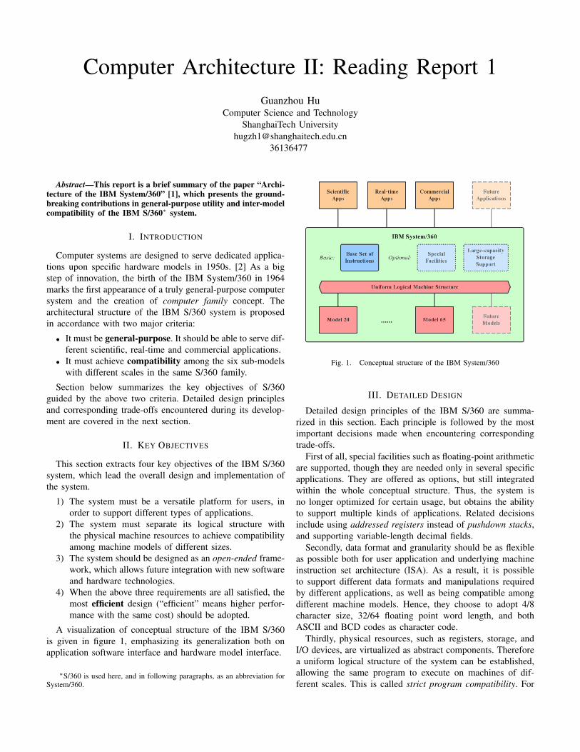
A visualization of conceptual structure of the IBM S/360is given in figure 1, emphasizing its generalization both onapplication software interface and hardware model interface.
∗S/360 is used here, and in following paragraphs, as an abbreviation forSystem/360.
Fig. 1. Conceptual structure of the IBM System/360
III. DETAILED DESIGN
Detailed design principles of the IBM S/360 are summa-rized in this section. Each principle is followed by the mostimportant decisions made when encountering correspondingtrade-offs.
First of all, special facilities such as floating-point arithmeticare supported, though they are needed only in several specificapplications. They are offered as options, but still integratedwithin the whole conceptual structure. Thus, the system isno longer optimized for certain usage, but obtains the abilityto support multiple kinds of applications. Related decisionsinclude using addressed registers instead of pushdown stacks,and supporting variable-length decimal fields.
Secondly, data format and granularity should be as flexibleas possible both for user application and underlying machineinstruction set architecture (ISA). As a result, it is possibleto support different data formats and manipulations requiredby different applications, as well as being compatible amongdifferent machine models. Hence, they choose to adopt 4/8character size, 32/64 floating point word length, and bothASCII and BCD codes as character code.
Thirdly, physical resources, such as registers, storage, andI/O devices, are virtualized as abstract components. Thereforea uniform logical structure of the system can be established,allowing the same program to execute on machines of dif-ferent scales. This is called strict program compatibility. For
example, they decide to build channels that present a standardinterface for the processor to communicate with various I/Odevices.
Last but not least, special attention is paid towards thefuture trends that storage capacity is growing larger, and newI/O devices and CPU function schemes are emerging (whichwill possibly introduce brand-new instructions). With suchanticipation, spare resources are reserved at all levels, such asspare bits in instructions, unused operation codes, and forward-looking support of larger memory space. [3] By this approach,S/360 makes it feasible to accept new devices, adopt new CPUinstructions, and handle a bigger storage.∗
IV. CONCLUSION
This report gives a brief summary of the key objectivesand innovative design philosophies of the IBM System/360.The system is designed to offer general-purpose support forscientific, real-time and commercial applications. It providesa compatible logical structure for the six sub-models withdifferent scales. Flexibility ranging from large-capacity storagesupport to instruction bits are also achieved. The IBM S/360is a pioneer of applying abstraction in computer architectures,and significantly influences future computer systems design.
REFERENCES
[1] G. M. Amdahl, G. A. Blaauw, and F. P. Brooks Jr., “Architecture of theibm system/360,” IBM Journal, 1964.
[2] F. P. Brooks Jr., “Recent developments in computer organization,” Ad-vances in Electronics, 1963.
[3] F. Brooks, G. H. Mealy, B. I. Witt, and W. A. Clark, “The functionalstructure of os/360,” Pioneers and Their Contributions to SoftwareEngineering, 2001.
∗Decisions which are discussed in the original paper but are left un-mentioned in this section, are mainly the ones where both choices offergeneralization and compatibility, but differs only in efficiency according totest statistics.
Computer Architecture II: Reading Report 2Guanzhou Hu
Computer Science and TechnologyShanghaiTech University
Abstract—This report is a brief summary of the article “TheFuture of Microprocessors” [1], which predicts that an inevitableparadigm shift towards Chip Multiprocessors (CMP) will be thefuture of microprocessors development∗.
I. INTRODUCTION
Since 1970s, the actual performance of microprocessorshas increased tremendously, even faster than the predictionof Moore’s law. [1] Such performance gain is achieved byapplying user-transparent technologies. On the memory side,a larger cache hierarchy is introduced. On the processor side,longer pipelines and superscalar processors were developed,resulting in more powerful single processors.
Unfortunately, due to the limitations described in SectionII, the attempt of enhancing individual processor performancehas met a hard bottleneck. Chip Multiprocessor (CMP)architecture, which integrates multiple processor cores ontoa single chip, will be the future direction instead.
II. PROBLEM BACKGROUND
Two traditional ways of enhancing the speed of processors,pipelining and superscalar technologies, both exploit Instruc-tion Level Parallelism (ILP). Recently, the performance gainfrom ILP on a single processor is approaching its own limit.This bottleneck exists because of the following three reasons:
1) Degree of parallelism among instructions is typicallyno more than four, as observed in most applicationinstruction streams. [2] Meanwhile, developing super-scalar processors that can issue more instructions isextremely expensive. Thus, the superscalar techniquecan no longer bring obvious speedup.
2) Larger number of pipeline stages will make each sep-arate stage too short to handle a reasonable task, andwill bring huge complexity and overhead to the circuit.Thus, finer-grained pipelining is also not able to furtherincrease single processor performance.
3) Pratical cooling systems will have difficulty serving evenhigher power consumption.
As a result, a higher level of parallelism should be intro-duced, which is Thread Level Parallelism (TLP) brought bythe CMP architecture.
∗Since this article is written in the year 2005, “future” here representsthe trend after that timepoint.
III. KEY IDEA OF CMPThe key idea of CMP is to gather multiple CPU cores
onto one single chip. According to different caching andmultithreading policies, CMP architecture can be roughlydivided into the following three categories, as shown in b),c), and d), Figure 4 of the article. [1]
• Simple chip multiprocessor, where each core is single-threaded, and diffrent cores do not share on-chip cache.
• Shared-cache (often called multicore processor thesedays), where the cores share an on-chip L2 cache.
• Multithreaded, shared-cache, where each core is fur-therly hyperthreaded.
IV. BENEFITS OF CMPBy integrating multiple cores onto one chip instead of barely
putting several individual processors together, CMPs have thepotential to make improvements for either throughput-sensitiveor latency-sensitive conditions.
For throughput-sensitive workloads like web servers, tasksare relatively independent and possibly I/O-bound, and latencyis not as critical. CMPs can bring significantly lower powerconsumption and better performance for such workloads.Firstly, for each core in the CMP, clock rate and superscalarlevel can be lowered, while the overall throughput is notinfluenced. This decreases the required voltage supply. Since
P ∝ V 2,
where P is consumed power and V is supplied voltage,theoretically a processor only require 1
k of the original powerto produce the same throughput, when k cores are integrated.Secondly, inter-processor communication will be much moreefficient because of reduced distance and increased bandwidthbetween cores.
For latency-sensitive workloads like desktop applications,CMP is still the best goal to head for. Latency L can bemodeled as:
L =cycles
r × s× p,
where “cycles” is the fixed total number of clock cycles neededto complete the task, r is clock rate, s is superscalar level, andp is degree of multiprogramming. As r and s have both beenpushed to the limit, multiprogramming (which increases p tomore than 1) becomes the only solution. Compared to codingparallel programs across separate processors, multiprogram-ming on CMPs are much easier because on-chip cores share
the same memory. [3] Since that parallel programming is anecessary route, shifting to CMP architecture will reduce thecost and difficulty for users to handle it.
Apart from software’s perspective, CMPs have advantageseven for hardware developers. Without the need of frequentlyadjusting clock rates, they require less engineering effortduring version updates. Similarly, the underlying system boarddoes not require major modifications caused by core logic re-design.
V. CONCLUSION
In summary, future microprocessors will shift to Chip Multi-processor architecture to overcome the performance bottleneckof single processors. CMPs can produce the same throughputwith significantly lower power consumption. They can makemultiprogramming much easier on shared memory, when user-defined parallelization is an inevitable trend. They can alsosimplify hardware updates between generations.
Such paradigm shift is a huge step in the history ofmicroprocessors development, also a necessary one. Regardingsoftware programmers, they also have to embrace multipro-cessor programming techniques to get synchronized with thisarchitectural transform, pushing code performance to a brand-new level.
VI. MY REFLECTION
Looking back from 2019, this prediction made by Prof.Olukotun and Dr. Hammond at 2005 is quite forward-lookingand accurate. Though such architectural design scheme isseldom mentioned as Chip Multiprocessor in recent years(instead, called multicore processor & hyperthreading), thisparadigm actually gets widely accepted and implemented.Almost all modern processors are built upon this pattern.
However, fact is that we cannot keep plugging in more andmore cores into a single chip, not to mention that the physicalsize of computer chips has been squeezed to quite a smalllevel these days. Such fact indicates that performance gainachieved by CMPs is once again reaching a limitation. It isprobably the time when we need new innovations in the fieldof processors, memory architecture, and I/O management, forexample in-memory / on-disk data pre-processing, to fight fora higher peak of computation performance.
REFERENCES
[1] K. Olukotun and L. Hammond, “The future of microprocessors,” ACMQueue, 2005.
[2] D. W. Wall, “Limits of instruction-level parallelism,” WRL ResearchReport, 1993.
[3] L. Hammond, B. D. Carlstrom, V. Wong, M. Chen, C. Kozyrakis,and K. Olukotun, “Transactional coherence and consistency: simplifyingparallel hardware and software,” IEEE Micro, 2004.
Computer Architecture II: Reading Report 3Guanzhou Hu
Computer Science and TechnologyShanghaiTech University
Abstract—This report is a brief summary of the article“An Overview of the Scala Programming Language”. [1] Scalaintegrates object-oriented model with functional programming,and makes a step forward to building true component softwaresystems.
I. INTRODUCTION
One of the key points to industrialize software developmentis to provide a true component system, so that larger prod-ucts can be easily assembled from pre-written libraries. Thisidea has been well established in hardware industry. On thecontrary, a big proportion of software applications are writtenfrom scratch, partially due to lack of component abstractionin common programming languages.
The work of Scala aims at providing a scalable program-ming language which better supports component abstraction.This goal is achieved through two approaches:
• Integrate object-oriented model (OOP) and functionalprogramming (FP).
• Provide composition and decomposition mechanisms,thus further supports implicit parameter inference.
The rest of this report will cover details of Scala’s im-plementation platform and compatibility (see Section II), itsmulti-view abstraction design combining OOP and FP (seeSection III), and its rich type system supporting componentcomposition and decomposition (see Section IV).
II. COMPATIBILITY WITH JAVA
A pragmatic programming language should be easily ap-plied to and vastly tested in real application developmentscenarios. In order to ease adoption by users, Scala is designedto execute upon Java Virtual Machine (JVM), thus has a greatcompatibility with Java and C#. However, Scala is not a super-set of Java. It reinterprets Java’s object hierarchy and typesystem, and adds in another view of functional programmingabstraction.
III. MULTI-VIEW ABSTRACTIONS
Designed as a statically typed language, Scala is the firstone which integrates object-oriented programming and func-tional programming. Such integration brings two differentperspectives of abstraction. First, OOP ensures “everythingare objects”, thus unifies numerical types, reference types,and user-defined types. Second, FP ensures “all operations arenormal values”, which brings great flexibility.
A. Object-oriented AbstractionTo follow the philosophy of object-oriented programming,
Scala purifies Java’s original object model. Every value, nomatter it is a numerical value or a reference value (such assequences), is an instance of an object. Consequently, everyoperation becomes a method call, even for variable access (forexample, x = e is interpreted as x_=(e)). Users can takeadvantage of this design in two ways. Firstly, all user-definedclasses have uniform formats and interfaces with embeddedclasses. Secondly, users can freely overload embedded opera-tions to build fancy interfaces and implement class properties.
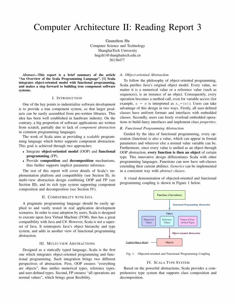
B. Functional Programming AbstractionGuided by the idea of functional programming, every op-
eration (function) is also a value, which can appear in formalparameters and wherever else a normal value variable can be.Furthermore, since every value is unified as an object throughOOP abstraction, every function is then an object of certaintype. This innovative design differentiates Scala with otherprogramming languages. Functions can now have sub-classesextending their current abilities. Generics can be implementedin a consistent way with abstract classes.
A visual demonstration of objected-oriented and functionalprogramming coupling is shown in Figure 1 below.
Fig. 1. Objected-oriented and Functional Programming Coupling
IV. SCALA TYPE SYSTEM
Based on the powerful abstractions, Scala provides a com-prehensive type system that supports class composition anddecomposition.
For class composition, Scala includes not only class inher-itance, but also traits, method shadowing, membership, andsuper calls. The combination of these techniques is calledMixin-class Composition. With the help of mixin composition,Scala programmers can now do things like defining a baseiterator class BaseIter, extending it to a generic GenIterand a specific StrIter, then combining their functionalitiesinto class Iter by:
class Iter extends StrIter(args(0))with GenIter[char];
For class decomposition, Scala allows a pattern matchingway of sub-typing. Instead of traditional object-oriented de-composition, where each sub-type must arrange their commonmethods in the same way as their parent, pattern matchingdecomposition uses a match-case expression on the inputand maps different sub-types onto different implementations.This brand-new approach of decomposition is far less error-prone.
With the help of the above mechanisms, Scala successfullyimplements the implicit expression that automatically in-fers argument types.
V. CONCLUSION
To summarize, Scala is an innovative JVM programminglanguage with multiple view of abstractions and a rich typesystem. Scala combines object-oriented programming modelwith functional programming, thus provides a highly uniformobject model. Its type system provides comprehensive tech-niques for class composition and decomposition, thereforefurther supports implicit parameter inference. These charac-teristics of Scala make it possible to build true componentsystems.
Though Scala is a lab-born language, it has been put intopractice in various projects, such as Facebook and Twitter. Itscomplicated characteristics put down more responsibility onlibrary developers, meanwhile promote the idea of componentabstraction and code reuse greatly.
REFERENCES
[1] M. Odersky, P. Altherr, V. Cremet, and etc., “An overview of the scalaprogramming language,” Technical Report LAMP REPORT, 2006.
Computer Architecture II: Reading Report 4Guanzhou Hu
Computer Science and TechnologyShanghaiTech University
Abstract—This report is a brief summary of the article “Opti-mizing for Parallelism and Data Locality” [1], which presentsa simple but accurate loop optimization algorithm to takeadvantage of both locality and parallelism at the same time.
I. INTRODUCTION
Parallelism and Data Locality are the two major drivingforces of compile-time loop optimization. Previous researchused to exploit parallelism and data locality separately∗. Incontrast, this paper makes an effort to create a straight-forwardloop optimization model which takes advantage of locality andparallelism simultaneously.
The rest of this report will cover the following aspects ofthe model:
• An overview of the optimization model (see Section II).• Details about data locality optimization on the inner-most
loop (see Section III).• Details about parallelism scheduling on the outer-most
loop (see Section IV).Section V will summarize the experiment results and Sec-
tion VI will conclude.
II. MODEL OVERVIEW
For simplicity, the model is designed to rearrange andadjust nested loops on shared-memory architecture for bet-ter performance. The model pursues two main objectives inconcert. First, cache line reuse should be exploited efficiently.Second, parallelism should be introduced in large granularity,while not significantly lowering the degree of locality (forexample, causing false sharing). Based on this guideline, theoptimization algorithm is divided into two sequential phases,as demonstrated in Figure 1.
Fig. 1. Overall Algorithm Phases
∗“Previous research” here refer to those before 1992.
Notice that parallelism is introduced and scheduled af-ter inner loop locality optimization. This order is importantwhen combining cache optimization with parallelization. Ifparallelism granularity and parallel loop order are fixed inthe first stage, then we can hardly improve cache line reuseafterwards, since it mostly requires significant adjustment inloop permutation. On the opposite, introducing parallelismafter locality optimization only requires slight modificationswhen the outer-most loop is non-parallelizable.
III. DATA LOCALITY OPTIMIZATION
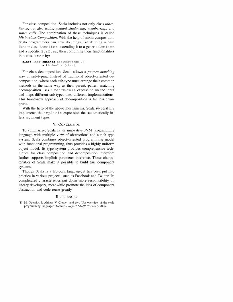
The first phase of the algorithm aims at optimizing datalocality by improving the cache line reuse rate. Based on theobservation that the inner-most loop often contains sufficientnumber of memory accesses which will completely flush thecache, the paper focuses on giving the lowest cost for theinner-most loop. This goal is achieved through the procedureshown in Figure 2.
Fig. 2. Data Locality Optimization Phase Algorithm
For every loop l, all references to the same memory locationcaptured when l is the innermost loop are grouped using
RefGroup. The groups are categorized into three differentaccess patterns: loop invariant, unit stride, and no reuse, eachcontributing to a different amount of cost. After summingup the total cost for every possible inner-most loop, they arepermuted in an order such that the inner loops cost less.
The permutation calculated above may not be legal. Undersuch circumstances, a nearby approximation needs to begenerated.
IV. PARALLELISM SCHEDULING
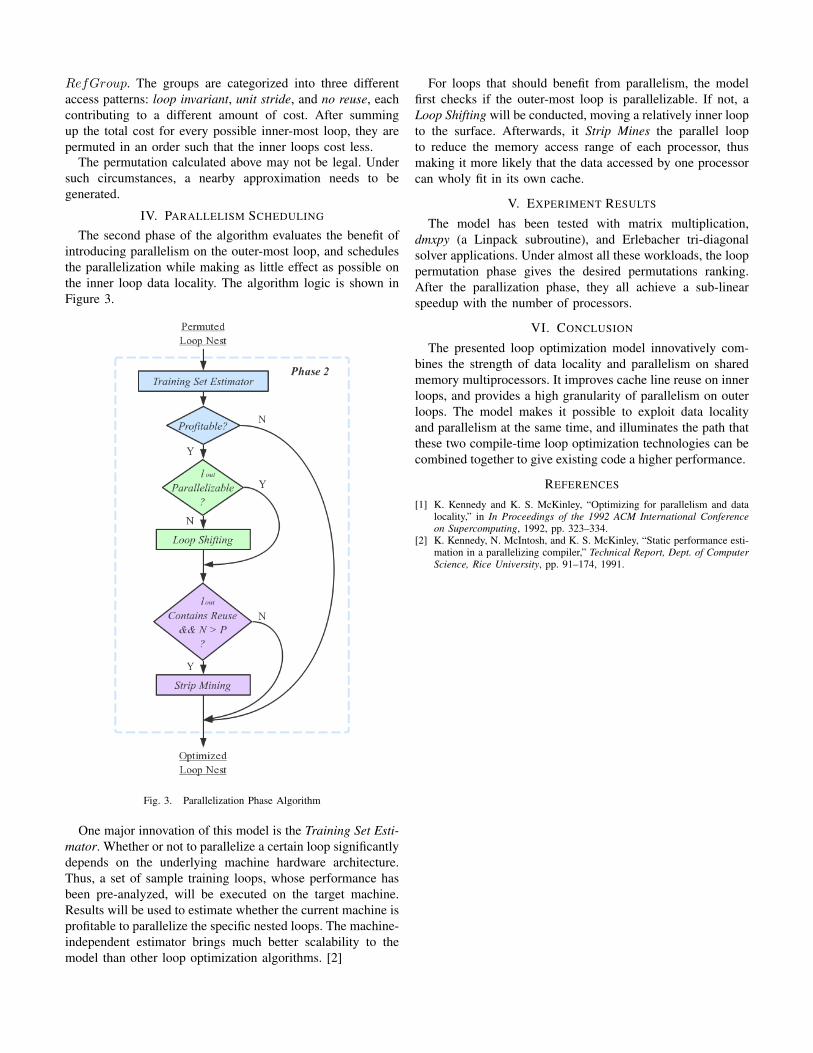
The second phase of the algorithm evaluates the benefit ofintroducing parallelism on the outer-most loop, and schedulesthe parallelization while making as little effect as possible onthe inner loop data locality. The algorithm logic is shown inFigure 3.
Fig. 3. Parallelization Phase Algorithm
One major innovation of this model is the Training Set Esti-mator. Whether or not to parallelize a certain loop significantlydepends on the underlying machine hardware architecture.Thus, a set of sample training loops, whose performance hasbeen pre-analyzed, will be executed on the target machine.Results will be used to estimate whether the current machine isprofitable to parallelize the specific nested loops. The machine-independent estimator brings much better scalability to themodel than other loop optimization algorithms. [2]
For loops that should benefit from parallelism, the modelfirst checks if the outer-most loop is parallelizable. If not, aLoop Shifting will be conducted, moving a relatively inner loopto the surface. Afterwards, it Strip Mines the parallel loopto reduce the memory access range of each processor, thusmaking it more likely that the data accessed by one processorcan wholy fit in its own cache.
V. EXPERIMENT RESULTS
The model has been tested with matrix multiplication,dmxpy (a Linpack subroutine), and Erlebacher tri-diagonalsolver applications. Under almost all these workloads, the looppermutation phase gives the desired permutations ranking.After the parallization phase, they all achieve a sub-linearspeedup with the number of processors.
VI. CONCLUSION
The presented loop optimization model innovatively com-bines the strength of data locality and parallelism on sharedmemory multiprocessors. It improves cache line reuse on innerloops, and provides a high granularity of parallelism on outerloops. The model makes it possible to exploit data localityand parallelism at the same time, and illuminates the path thatthese two compile-time loop optimization technologies can becombined together to give existing code a higher performance.
REFERENCES
[1] K. Kennedy and K. S. McKinley, “Optimizing for parallelism and datalocality,” in In Proceedings of the 1992 ACM International Conferenceon Supercomputing, 1992, pp. 323–334.
[2] K. Kennedy, N. McIntosh, and K. S. McKinley, “Static performance esti-mation in a parallelizing compiler,” Technical Report, Dept. of ComputerScience, Rice University, pp. 91–174, 1991.
Computer Architecture II: Reading Report 5Guanzhou Hu
Computer Science and TechnologyShanghaiTech University
Abstract—This report is a brief summary of the article “GPFS:A Shared-Disk File System for Large Computing Clusters” [1],which describes the main features of GPFS, a massively scalableparallel cluster file system developed by IBM.
I. INTRODUCTION
As modern computer clusters becoming larger and larger, atraditional file system can no longer manage the complicatedstorage issues effectively. Distributed local file systems canhardly cooperate with each other, while simple parallel filesystems are not scalable enough.
GPFS (General Parallel File System) is a scalable parallelfile system designed by IBM to serve large-scale shared-disk clusters. The rest of this report will cover the followingessential features of GPFS:• An overview of shared-disk architecture (see Section II).• Exploiting parallelism in multi-aspects (see Section III).• Details of synchronization strategies (see Section IV).• Fault tolerance and recovery techniques (see Section V).Then Section VI will conclude.
II. SHARED-DISK ARCHITECTURE
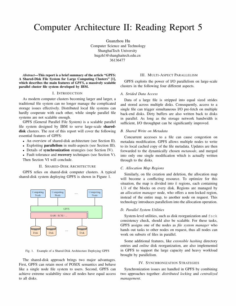
GPFS relies on shared-disk computer clusters. A typicalshared-disk system deploying GPFS is shown in Figure 1.
Fig. 1. Example of a Shared-Disk Architecture Deploying GPFS
The shared-disk approach brings two major advantages.First, GPFS can retain most of POSIX semantics and behavelike a single node file system to users. Second, GPFS canachieve extreme scalability since all nodes have equal accessto all disks.
III. MULTI-ASPECT PARALLELISM
GPFS exploits the power of I/O parallelism on large-scaleclusters in the following four different aspects.
A. Strided Data Access
Data of a large file is stripped into equal sized stridesand stored across multiple disks. Consequently, access to asingle file can trigger simultaneous I/O pre-fetch on multipleback-end disks. Dirty buffers are also written back to disksin parallel. As long as the storage network bandwidth issufficient, I/O throughput can be significantly improved.
B. Shared Write on Metadata
Concurrent accesses to a file can cause congestion onmetadata modification. GPFS allows multiple nodes to writeto its local cached copy of the file metadata. Updates are thenforwarded to the dynamically chosen metanode, and mergedinto only one single modification which is actually writtenthrough to the disks.
C. Allocation Map Regions
Similarly, on file creation and deletion, the allocation mapwill become a conflicting resource. To optimize for thissituation, the map is divided into k regions, each containing1/k of the blocks on every disk. Regions are managed byan allocation manager node, who offers a non-locked region,instead of the entire map, to another node on request. Thistechnology introduces parallelism into the allocation operation.
D. Parallel System Utilities
System-level utilities, such as disk reorganization and fsckconsistency check, should also be scalable. For these tasks,GPFS assigns one of the nodes as file system manager whohands out tasks to other nodes on request, thus all nodes canwork on subsets of files in parallel.
Some additional features, like extensible hashing directoryentries and online disk reorganization, are also implementedin GPFS to support the large capacity and heavy workloadbrought by parallelism.
IV. SYNCHRONIZATION STRATEGIES
Synchronization issues are handled in GPFS by combiningtwo approaches together: distributed locking and centralizedmanagement.
A. Distributed Locking
File data access in GPFS is fundamentally based on byte-ranged distributed locking (in fact block-ranged in order to becompatible with allocations discussed in Section III-C). Eachfile is associated with a specific node m called global lockmanager, who is responsible for handing out lock tokens toother nodes on request. A granted token represents the right ofnode n to read and modify a range of file blocks [bstart, bend],originally covering the whole file. If node n′ requests a write tothe locked region, meanwhile their destinations actually do notoverlap, then the token splits into two, and the correspondinghalf is given to n′.
This locking scheme is called “distributed” since the locksare eventually held by each node distributively. Communica-tion between the requester n′ and the lock manager m willonly involve one query and one lock information update perrequest. The actual token splitting task is done by the holdern. Thus, the global lock manager can afford a high degree ofscalability and will not become a serious bottleneck when thesystem scales.
For small but frequently accessed files, such locking schemecan still result in catastrophic performance downgrade. Datashipping is used under these circumstances as a compensation.
B. Centralized Management
Since GPFS innovatively parallelizes metadata operationsand disk block allocations, they also require proper syn-chronization. As stated in Section III-B and III-C, they aresynchronized in a more centralized manner, using a metanodeand an allocation manager. The reason is that these operationsare small, frequent, and fragmented, so that distributed lockingwill cause many lock conflicts. A centralized manager, incontrast, will be able to schedule resources, avoid most ofthe conflicts, and gather and reduce individual results.
V. FAULT TOLERANCE
In large-scale computer clusters, failures can happen fre-quently. For node failures, GPFS adopts write-ahead logs,which are widely used in journaling file systems like ext[2], to ensure the file system consistency. File operations froma node must first append a corresponding transaction in its logbefore the actual execution. Since disks are shared, a survivalnode can recover the log transactions on behalf of the failednode. Special roles played by the failed node, such as a lockmanager, will also be taken over. For communication failures,the majority group will continue to function as a cluster, whilethe rest of the nodes wait until communication recovery. Fordisk failures, GPFS mainly utilizes RAID for error recovery.Manual replication is also supported but rarely enabled.
VI. CONCLUSION
GPFS is a collection of many brilliant ideas in file systemdesign. It exploits parallelism not only in data accesses,but also in metadata operations, disk block allocations, andadministrative utilities. It takes advantage of both distributed
locking and centralized management to maintain synchroniza-tion correctness. It also adopts write-ahead logs to achievefault tolerance.
GPFS has been installed and tested on the largest supercomputers in the world∗. It makes a big step forward in parallelfile system scalability and stability. Up to now (the year 2019),GPFS and its evolutionary version IBM Specturm Scale arestill widely installed on high performance computer clusters.
REFERENCES
[1] F. B. Schmuck and R. L. Haskin, “Gpfs: A shared-disk file system forlarge computing clusters,” in FAST, 2002.
[2] Wikipedia, “Journaling file system — Wikipedia, the free ency-clopedia,” http://en.wikipedia.org/w/index.php?title=Journaling\%20file\%20system&oldid=869377481, 2019, [Online; accessed 21-March-2019].
∗In the year 2002 when this paper is published, the largest clusterdeploying GPFS refers to IBM ASCI White [1].
Computer Architecture II: Reading Report 6Guanzhou Hu
Computer Science and TechnologyShanghaiTech University
Abstract—This report is a brief summary of the article “24/7Characterization of Petascale IO Workloads” [1]. It presents ascalable I/O profiling tool, Darshan, which captures application-level I/O patterns meanwhile introducing negligible overhead tothe system.
I. INTRODUCTION
Existing I/O profiling tools go into two extreme categories.The first category logs every individual I/O operation anddoes not provide postprocessing. They introduce considerableoverhead, thus are not scalable enough. The second categoryadopts sampling techniques to avoid huge overhead, howeversacrifices the ability to capture user access patterns. With thescale of computation growing rapidly nowadays, an I/O char-acterization tool which combines application-level reflectionwith scalability is in need.
The paper presents a new I/O profiling tool, Darshan, whichpossesses the following three advantages. Firstly, it capturesuser-level file access patterns. Secondly, it is transparent tousers, leaving no need for application API modifications.Thirdly, it achieves peta-scale scalability, making it possibleto deploy Darshan on the world’s largest HPC systems.
The rest of this report will cover:• An overview of Darshan tool (see Section II).• Implementation details of Darshan (see Section III).• Test results on real machines (see Section IV).Section V concludes, and Section VI contains my own
reflection on this paper.
II. OVERVIEW OF DARSHAN
Darshan is implemented as a set of user space libraries. Itcurrently supports capturing MPI-IO routines and POSIX rou-tines. MPI-IO routines are supervised through PMPI interface,while POSIX routines are traced by wrapping over originalsystem call functions.
Upon successful linking, user space library organizationensures Darshan’s user transparency. The logging is conductedby each process individually when it issues an I/O operation.Results will be gathered, reduced, and written to disk in aspecified format at process termination.
III. IMPLEMENTATION DETAILS
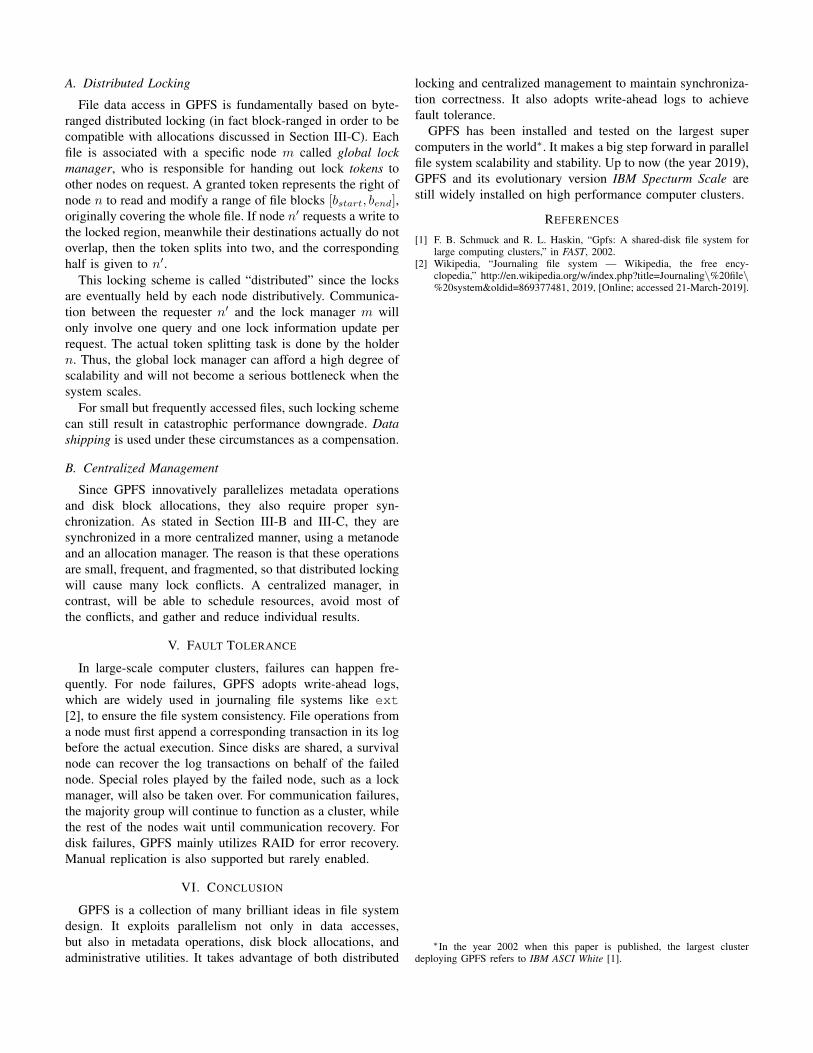
For every process, Darshan records the captured I/O infor-mation into file record structures, which reside in the processmemory space. Each file record corresponds to one physical
file that the process interacts with, and can be indexed throughfile name, file descriptor, or MPI file handle hashing.
Inside the file record, an array of counters are maintained.Users can specify what information should be tracked as coun-ters, for example number of POSIX operations and total byteswritten. Additionally, access sizes and stride sizes∗ are keptin two red-black trees respectively for pattern characterizationanalysis. A demonstration of Darshan file record organizationis given in Figure 1.
Fig. 1. Darshan File Record Organization
To achieve higher scalability, file records are not collecteduntil process termination. Thus, extra I/O communicationsonly occur when a process finishes, introducing much lessoverhead throughout most of the execution time. Reductionon shared file records across MPI processes, and output datacompression, will both be conducted to minimize the writesize. Furthermore, users are allowed to set the limit of numberof files to trace by each process, and what counters to keeptrack of in a file record, to tune a better performance for user-specific workloads.
IV. REAL MACHINE TESTING
Darshan has been deployed on LANL IBM BlueGene/Psupercomputing system, and tested on four different user
∗Stride used here to indicate an interval between accesses. This is a totallyindependent concept with respect to data striding.
benchmarks or applications: MADBench2, Combo I/O, S3D-IO, and HOMME. Test results reveal that Darshan introduceslittle runtime overhead in either function wrapping executiontime (< 0.52%) and memory occupation (< 0.2%). Also, logoutput optimizations suppress extra write-back time below 7seconds for various job sizes. These advantages make Darshancapable of handling peta-scale workloads of over 65,536processes.
V. CONCLUSION
In summary, Darshan is a highly scalable I/O character-ization tool which tracks user application I/O access pat-terns, meanwhile introducing little overhead into the system.Darshan makes it possible to contiguously trace user-levelI/O operations on large-scale supercomputing systems. Theselarge-scale comprehensive traces will promote the storagecommunity’s understanding of how modern computationalscience applications interact with storage, therefore illuminatesthe future path of high-performance storage techniques.
VI. MY REFLECTIONS
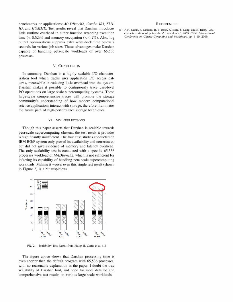
Though this paper asserts that Darshan is scalable towardspeta-scale supercomputing clusters, the test result it providesis significantly insufficient. The four case studies conducted onIBM BG/P system only proved its availability and correctness,but did not give evidence of memory and latency overhead.The only scalability test is conducted with a specific 65,536processes workload of MADBench2, which is not sufficient forinferring its capability of handling peta-scale supercomputingworkloads. Making it worse, even this single test result (shownin Figure 2) is a bit suspicious.
Fig. 2. Scalability Test Result from Philip H. Carns et al. [1]
The figure above shows that Darshan processing time iseven shorter than the default program with 65,536 processes,with no reasonable explanation in the paper. I doubt the truescalability of Darshan tool, and hope for more detailed andcomprehensive test results on various large-scale workloads.
REFERENCES
[1] P. H. Carns, R. Latham, R. B. Ross, K. Iskra, S. Lang, and K. Riley, “24/7characterization of petascale i/o workloads,” 2009 IEEE InternationalConference on Cluster Computing and Workshops, pp. 1–10, 2009.
Computer Architecture II: Reading Report 7Guanzhou Hu
Computer Science and TechnologyShanghaiTech University
Abstract—This report is a brief summary of the article“Adaptable, Metadata Rich IO Methods for Portable HighPerformance IO” [1]. It presents an adaptable high-performanceI/O framework called ADIOS, which provides a portable andefficient interface between scientific computing applications andlow-level I/O libraries.
I. INTRODUCTION
Various I/O libraries, such as HDF5 and NetCDF, havebeen developed to serve high-performance scientific comput-ing. However, for different applications running on differenthardware platforms, different I/O libraries show differentperformance. With the variety of HPC hardware resourcesincreasing, an abstract layer that wraps over low-level I/Omethods is in need.
This paper presents ADIOS (ADaptive I/O System), an I/Omethod abstraction layer developed by Oak Ridge NationalLab that provides portable switching among I/O librariesand significantly improves the I/O performance of scientificcomputing applications. The rest of this report will cover thefollowing aspects of ADIOS:
• An overview of ADIOS architecture (see Section II).• Intermediate BP format representation (see Section III).• Run-time selection of I/O methods (see Section IV).• Data characteristics collection (see Section V).Section VI will then conclude.
II. OVERVIEW OF ADIOS
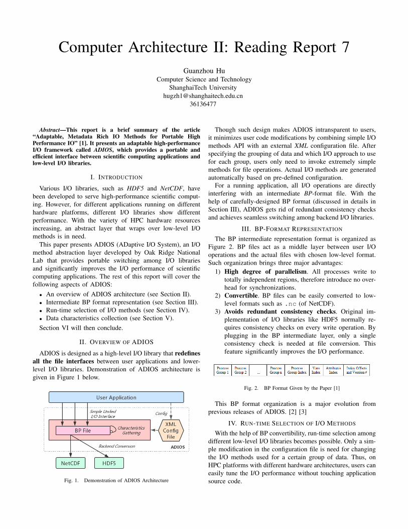
ADIOS is designed as a high-level I/O library that redefinesall the file interfaces between user applications and lower-level I/O libraries. Demonstration of ADIOS architecture isgiven in Figure 1 below.
Fig. 1. Demonstration of ADIOS Architecture
Though such design makes ADIOS intransparent to users,it minimizes user code modifications by combining simple I/Omethods API with an external XML configuration file. Afterspecifying the grouping of data and which I/O approach to usefor each group, users only need to invoke extremely simplemethods for file operations. Actual I/O methods are generatedautomatically based on pre-defined configuration.
For a running application, all I/O operations are directlyinterfering with an intermediate BP-format file. With thehelp of carefully-designed BP format (discussed in details inSection III), ADIOS gets rid of redundant consistency checksand achieves seamless switching among backend I/O libraries.
III. BP-FORMAT REPRESENTATION
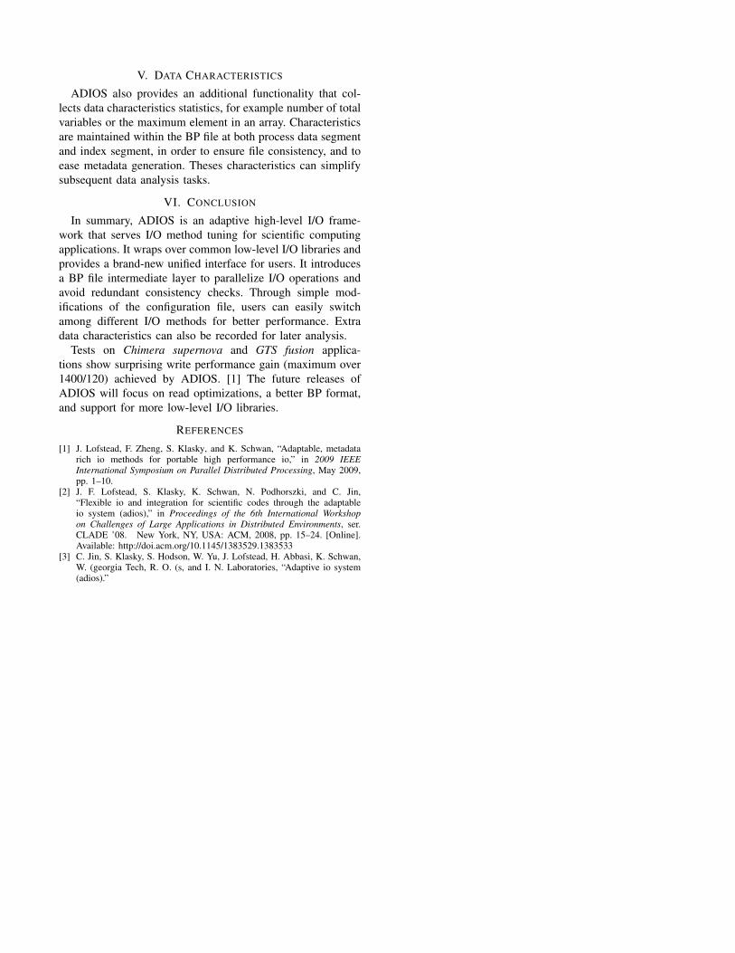
The BP intermediate representation format is organized asFigure 2. BP files act as a middle layer between user I/Ooperations and the actual files with chosen low-level format.Such organization brings three major advantages:
1) High degree of parallelism. All processes write tototally independent regions, therefore introduce no over-head for synchronizations.
2) Convertible. BP files can be easily converted to low-level formats such as .nc (of NetCDF).
3) Avoids redundant consistency checks. Original im-plementation of I/O libraries like HDF5 normally re-quires consistency checks on every write operation. Byplugging in the BP intermediate layer, only a singleconsistency check is needed at file conversion. Thisfeature significantly improves the I/O performance.
Fig. 2. BP Format Given by the Paper [1]
This BP format organization is a major evolution fromprevious releases of ADIOS. [2] [3]
IV. RUN-TIME SELECTION OF I/O METHODS
With the help of BP convertibility, run-time selection amongdifferent low-level I/O libraries becomes possible. Only a sim-ple modification in the configuration file is need for changingthe I/O methods used for a certain group of data. Thus, onHPC platforms with different hardware architectures, users caneasily tune the I/O performance without touching applicationsource code.
V. DATA CHARACTERISTICS
ADIOS also provides an additional functionality that col-lects data characteristics statistics, for example number of totalvariables or the maximum element in an array. Characteristicsare maintained within the BP file at both process data segmentand index segment, in order to ensure file consistency, and toease metadata generation. Theses characteristics can simplifysubsequent data analysis tasks.
VI. CONCLUSION
In summary, ADIOS is an adaptive high-level I/O frame-work that serves I/O method tuning for scientific computingapplications. It wraps over common low-level I/O libraries andprovides a brand-new unified interface for users. It introducesa BP file intermediate layer to parallelize I/O operations andavoid redundant consistency checks. Through simple mod-ifications of the configuration file, users can easily switchamong different I/O methods for better performance. Extradata characteristics can also be recorded for later analysis.
Tests on Chimera supernova and GTS fusion applica-tions show surprising write performance gain (maximum over1400/120) achieved by ADIOS. [1] The future releases ofADIOS will focus on read optimizations, a better BP format,and support for more low-level I/O libraries.
REFERENCES
[1] J. Lofstead, F. Zheng, S. Klasky, and K. Schwan, “Adaptable, metadatarich io methods for portable high performance io,” in 2009 IEEEInternational Symposium on Parallel Distributed Processing, May 2009,pp. 1–10.
[2] J. F. Lofstead, S. Klasky, K. Schwan, N. Podhorszki, and C. Jin,“Flexible io and integration for scientific codes through the adaptableio system (adios),” in Proceedings of the 6th International Workshopon Challenges of Large Applications in Distributed Environments, ser.CLADE ’08. New York, NY, USA: ACM, 2008, pp. 15–24. [Online].Available: http://doi.acm.org/10.1145/1383529.1383533
[3] C. Jin, S. Klasky, S. Hodson, W. Yu, J. Lofstead, H. Abbasi, K. Schwan,W. (georgia Tech, R. O. (s, and I. N. Laboratories, “Adaptive io system(adios).”
Computer Architecture II: Reading Report 8Guanzhou Hu
Computer Science and TechnologyShanghaiTech University
Abstract—This report is a brief summary of the article“Parallel netCDF: A High-Performance Scientific I/O Interface”[1], which presents a set of parallel I/O interfaces for netCDFscientific data library, called PnetCDF.
I. INTRODUCTION
Portable I/O libraries, such as HDF and netCDF, havebeen widely used in modern scientific computing applica-tions. Though HDF5 has already adopted parallel I/O access,netCDF is still stuck in serial I/O methods∗, which becomes abottleneck for large-scale datasets. Considering that netCDFis popular in the field of earth modeling and simulation,developing a parallel I/O interface for netCDF format is inurgence.
The paper presents PnetCDF, a set of parallel netCDF I/Ointerfaces built upon MPI-IO methods. It exploits paralleliza-tion in netCDF file operations, while only introducing minormodifications in user API. It brings tremendous performancegain for netCDF applications. The rest of this report will cover:
• Original netCDF design (see Section II).• Overview of PnetCDF structure (see Section III).• Implementation of PnetCDF (see section IV).• Advantages and performance evaluation (see Section V).Section VI will then conclude, and my own reflections will
be given.
II. ORIGINAL NETCDF
NetCDF is a widely-used I/O utility for self-describing,structured, array-based datasets. It is originally developedby Unidata community of National Center for AtmosphericResearch (NCAR), and now becomes the most popular I/Olibrary for earth and atmospheric science applications. [2]NetCDF consists of a portable data file format (.nc) and aset of programming APIs for corresponding file interactions.
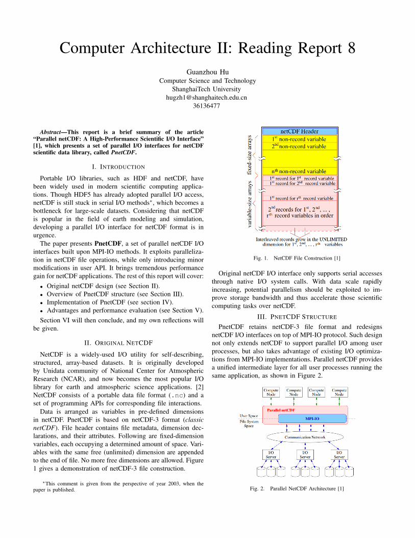
Data is arranged as variables in pre-defined dimensionsin netCDF. PnetCDF is based on netCDF-3 format (classicnetCDF). File header contains file metadata, dimension dec-larations, and their attributes. Following are fixed-dimensionvariables, each occupying a determined amount of space. Vari-ables with the same free (unlimited) dimension are appendedto the end of file. No more free dimensions are allowed. Figure1 gives a demonstration of netCDF-3 file construction.
∗This comment is given from the perspective of year 2003, when thepaper is published.
Fig. 1. NetCDF File Construction [1]
Original netCDF I/O interface only supports serial accessesthrough native I/O system calls. With data scale rapidlyincreasing, potential parallelism should be exploited to im-prove storage bandwidth and thus accelerate those scientificcomputing tasks over netCDF.
III. PNETCDF STRUCTURE
PnetCDF retains netCDF-3 file format and redesignsnetCDF I/O interfaces on top of MPI-IO protocol. Such designnot only extends netCDF to support parallel I/O among userprocesses, but also takes advantage of existing I/O optimiza-tions from MPI-IO implementations. Parallel netCDF providesa unified intermediate layer for all user processes running thesame application, as shown in Figure 2.
Fig. 2. Parallel NetCDF Architecture [1]
For netCDF file creation/open operations, the interfaceaccepts a MPI communicator group as an additional argument.It specifies which processes are involved in interacting withthis file. Data access operations, such as reading and writinga variable, are extended into two different sets of API. Thehigh-level API follows original netCDF functions to serveeasy accesses to contiguous regions, while the flexible APIprovides low-level MPI-style functions to handle accesses tonon-contiguous regions.
IV. PARALLEL IMPLEMENTATION
On the top level, PnetCDF provides a new collection ofnetCDF user I/O interfaces, where each function name isprefixed with “ncmpi_”. Under the bottom level, PnetCDFinvokes the ROMIO implementation of MPI-IO. Features likecollective I/O (I/O forwarding) used in ROMIO can thus bringfurther bandwidth improvement other than parallelization.
Every process maintains a cached copy of file header inits local memory during the I/O procedure, therefore meta-dataset operations no longer needs inter-process communi-cation. Consistency is ensured by MPI convention that allprocesses should always call a MPI function with exactly thesame arguments.
For actual data access, each process is assigned a differentMPI file view corresponding to a different segment of the filebody. Users can give extra MPI hints to guide the collectiveI/O, when they are accessing non-contiguous variable records.
V. EVALUATION
PnetCDF offers the following two advantages compared toserial netCDF and HDF5:
1) Due to the straight-forward format of netCDF files, ma-ture MPI-IO methods are easily applied without addingcomplicated transformation layers. Thus, only a minoramount of overhead is introduced.
2) File header caching removes most of the need of meta-data synchronization, therefore metadata updates are lesslikely to be the I/O bottleneck.
Experiments have been conducted on IBM SP-2 machines.Scalability tests over a synthetic three-dimensional datasetshow that PnetCDF significantly enlarges read/write band-width. Even when there is only one process, write performanceis improved with the help of collective I/O. Comparison testsover FLASH I/O benchmark also indicate that PnetCDF bringsless overhead than HDF5.
VI. CONCLUSION AND REFLECTIONS
In summary, PnetCDF provides a new set of parallel I/Ointerfaces for the netCDF library. It perfectly couples netCDFfile format with underlying MPI-IO methods to achieve sig-nificant performance optimizations. The successful implemen-tation of PnetCDF makes netCDF a more powerful tool forlarge-scale, structured data storage on modern machines.
Looking back from 2019, there is a little pity that parallelnetCDF still only supports netCDF-3 (classic) format [3],which is getting outdated. New netCDF-4 standard supports
multiple unlimited dimensions, which is much more flexible.However, current netCDF-4 implementation is built upon aHDF5 intermediate layer. Possibilities exist that PnetCDFcan be extended to support netCDF-4 to achieve both highperformance and high flexibility.
REFERENCES
[1] J. Li, W. keng Liao, A. Choudhary, R. Ross, R. Thakur, W. Gropp,R. Latham, A. Siegel, B. Gallagher, and M. Zingale, “Parallel netcdf:A high-performance scientific i/o interface,” in SC ’03: Proceedings ofthe 2003 ACM/IEEE Conference on Supercomputing, Nov 2003, pp. 39–39.
[2] “Netcdf url,” https://www.unidata.ucar.edu/software/netcdf/.[3] “Netcdf architecture,” https://www.unidata.ucar.edu/software/netcdf/docs/
netcdf introduction.html#architecture.
Computer Architecture II: Reading Report 9Guanzhou Hu
Computer Science and TechnologyShanghaiTech University
Abstract—This report is a brief summary of the article “zFS:A Scalable Distributed File System Using Object Disks” [1]. Itintroduces an IBM research project called zFS, an object disk-based file system that integrates a cooperative memory cache andis highly scalable.∗
I. INTRODUCTION
With commodity Object Store Devices (OSDs) entering thestorage market, a reliable and scalable file system for objectdisks is in need. To dig the potential of decentralization inOSDs, zFS is proposed as a highly distributed file system foroff-the-shelf commodity OSDs.
zFS integrates all individual machines’ memory into aglobal cache. It also applies distributed managers for dataand metadata accesses. The rest of this report covers thefollowing aspects of zFS:
• Overview of zFS architecture (see Section II).• Cooperative Global Cache (see Section III).• Distributed Management Schemes (see Section IV).Then Section V will conclude.
II. ZFS ARCHITECTURE
zFS separates high-level file management apart from low-level storage devices.
A. Low-level Disk Management
For every object disk in the storage system, zFS deploys alocal Object Store (OSD) to interact with the disk. File datais indexed through (obs, oid) pairs, where obs is objectdisk id, and oid is object id on the corresponding disk. OSDsprovide upper modules a uniform API to interact with fileobjects.
B. High-level File Modules
The essential part of zFS lies in its dedicated high-level filemanagement modules. There are five main modules involved:
1) Front End (FE): An FE instance is running in everyclient node kernel. It presents a standard POSIX APIfor users to conduct I/O with zFS.
2) Lease Manager (LMGR): For every underlying OSD,there exists a corresponding LMGR. Holder of an OSDmajor lease acts as the LMGR for that disk, thus isresponsible for sending out and revoking object leases
∗Attention: This project is not related to ZFS (Zettabyte File System)developed by Sun Microsystems.
regarding that disk. Leases (locks with certain expirationperiod) are used here to accommodate resource failures.
3) File Manager (FMGR): Each opened file is linked with aFMGR, held by the first machine to open the file. FMGRsare responsible for listening to user requests from FE,interact with corresponding LMGRs, and translate theoperations to OSDs.
4) Transaction Server (TSVR): A TSVR resides in everyclient node, which listens to FE for directory operations(i.e. metadata operations like rename()), and conductthem as proper transactions.
5) Cooperative Cache (Cache): zFS innovatively com-bines all client memory as a global cooperative cache.Details are discussed in Section III.
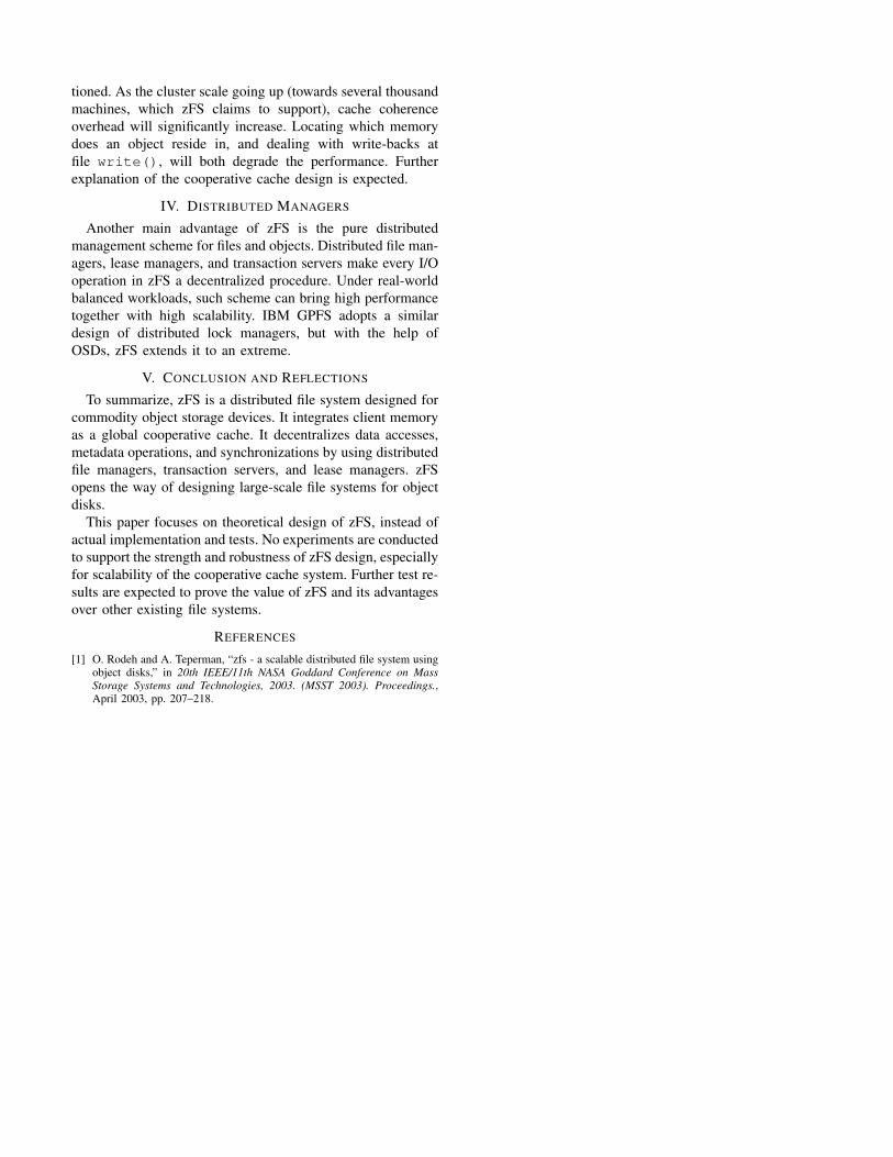
Organization of zFS components and their intercommuni-cations are demonstrated in Figure 1.
Fig. 1. zFS Architecture Design
III. COOPERATIVE CACHE
One major innovation of zFS project is the design ofcooperative cache. By integrating all individual machines’memory into a global page cache, read() performance canget improved. If one client is reading a file object that iscurrently cached in another machine, it fetches data directlyfrom the remote memory over RDMA, instead of going all theway through to disks.
However, since the paper does not include any test results,scalability of such cooperative cache design should be ques-
tioned. As the cluster scale going up (towards several thousandmachines, which zFS claims to support), cache coherenceoverhead will significantly increase. Locating which memorydoes an object reside in, and dealing with write-backs atfile write(), will both degrade the performance. Furtherexplanation of the cooperative cache design is expected.
IV. DISTRIBUTED MANAGERS
Another main advantage of zFS is the pure distributedmanagement scheme for files and objects. Distributed file man-agers, lease managers, and transaction servers make every I/Ooperation in zFS a decentralized procedure. Under real-worldbalanced workloads, such scheme can bring high performancetogether with high scalability. IBM GPFS adopts a similardesign of distributed lock managers, but with the help ofOSDs, zFS extends it to an extreme.
V. CONCLUSION AND REFLECTIONS
To summarize, zFS is a distributed file system designed forcommodity object storage devices. It integrates client memoryas a global cooperative cache. It decentralizes data accesses,metadata operations, and synchronizations by using distributedfile managers, transaction servers, and lease managers. zFSopens the way of designing large-scale file systems for objectdisks.
This paper focuses on theoretical design of zFS, instead ofactual implementation and tests. No experiments are conductedto support the strength and robustness of zFS design, especiallyfor scalability of the cooperative cache system. Further test re-sults are expected to prove the value of zFS and its advantagesover other existing file systems.
REFERENCES
[1] O. Rodeh and A. Teperman, “zfs - a scalable distributed file system usingobject disks,” in 20th IEEE/11th NASA Goddard Conference on MassStorage Systems and Technologies, 2003. (MSST 2003). Proceedings.,April 2003, pp. 207–218.
Computer Architecture II: Reading Report 10Guanzhou Hu
Computer Science and TechnologyShanghaiTech University
Abstract—This report is a brief summary of the short paper“Recent Progress in Tuning Performance of Large-scale I/O withParallel HDF5” [1], which summarizes current work on tuningHDF5 performance for scientific computing applications MOABand VPIC.
I. INTRODUCTION
Large-scale scientific applications put tremendous pressureon the underlying storage system. In simulation phases, mas-sive amount of data needs to be stored in files. In analysisphases, data files are read through different access patterns.Parallel I/O optimizations thus become essential to modernhigh-performance computing.
HDF5 is a widely-used I/O optimization library, whichsupports mainstream programming languages and is portableon various kinds of hardware platforms [2]. Parallel I/O inHDF5 is achieved through collective MPI-IO. This short paperpresents recent progress on optimizing HDF5 performance fortwo scientific computing applications:
• Mesh-Oriented DatABase (MOAB, see Section II).• Vector Particle-In-Cell (VPIC, see Section III).
II. MOAB ON MIRA
Mesh-Oriented Database (MOAB) is package for operatingmesh data [3]. It originally uses HDF5 to store and representmesh data structures.
Problem. MOAB assigns each process to read from adifferent coordinate in the mesh. This results in poor localityin HDF5 file accesses, thus cannot benefit from collective I/O.
Tuning. In HDF5, subset of data is accessed through hyper-slabs. An improved hyperslab selection algorithm that mergesmultiple non-contiguous hyperslabs into a hyperslam cansignificantly reduce the number of read calls. On Mira systemof Argonne National Lab (ANL), this approach achieves 10xperformance gain.
III. VPIC ON BLUE WATERS
Vector Particle-in-Cell (VPIC) is an application for simulat-ing plasma physics phenomenon. Its VPIC-IO kernel is alsobuilt upon HDF5.
Problem. As the number of processes increase, more parti-cles are written simultaneously into the same HDF5 data file.This introduces a potential I/O bottleneck.
Tuning. Two techniques are proposed to solve improveVPIC-IO performance. Firstly, write load among processes andamong I/O servers are re-distributed. Secondly, a new feature
called multi-dataset writes is introduced into HDF5, so thatdifferent datasets can be stored in one HDF5 file withoutserial collective operations. On Blue Waters system of theNational Center for Supercomputing Applications (NCSA),such approach achieves at least 2x speedup.
IV. CONCLUSION AND REFLECTIONS
Modern scientific computing applications are becomingmore complicated and more personalized. Though parallel I/Olibraries like HDF5 can provide a uniform storage optimizationscheme, we can never ignore the importance of tuning I/Ooperations for individual applications. In order to push thethroughput of scientific computing to an extreme, user-specificI/O pattern analysis and performance tuning should alwaysplay an important role.
REFERENCES
[1] M. S. Breitenfeld, K. Chadalavada, R. Sisneros, S. Byna, Q. Koziol,N. Fortner, M. Prabhat, and V. Vishwanath, “Recent progress in tuningperformance of large-scale i/o with parallel hdf5,” in 9th Parallel DataStorage Workshop (PDSW 2014), 2014.
[2] (2017) Hdf5 introduction. [Online]. Available: https://support.hdfgroup.org/HDF5/whatishdf5.html
[3] (2019) Moab:mesh-oriented database. [Online]. Available: https://bitbucket.org/fathomteam/moab
Computer Architecture II: Reading Report 11Guanzhou Hu
Computer Science and TechnologyShanghaiTech University
Abstract—This report is a brief summary of the article“Resilient Distributed Datasets: A Fault-Tolerant Abstraction forIn-Memory Cluster Computing” [1]. It presents a distributedmemory abstraction model called Resilient Distributed Datasets(RDDs). It implements RDDs into a framework called Spark thatenables fault-tolerant, efficient in-memory cluster computing.
I. INTRODUCTION
Existing high-level cluster computing frameworks (likeHadoop MapReduce [2]) are inefficient in reusing intermediateresults. At the end of a computation stage, all generated resultsneed to be written back to external stable storage such asdisks. To overcome this problem, many domain-specific in-memory frameworks have been developed. They pursue highperformance by sacrificing generality.
This paper presents Resilient Distributed Datasets (RDDs)that abstract distributed memory in a coarse-grained way.RDDs allow lazy computation and efficient fault recoverywith the help of lineage logging. RDDs naturally improve theperformance of iterative algorithms over batch operations. Therest of this report will cover:
• RDD model of data abstraction (see Section II).• The Spark system that implements RDD with Scala
programming language (see Section III).• Performance evaluation and results (see Section IV).Section V will then conclude and contain my own reflec-
tions.
II. RDD ABSTRACTION
An RDD is a read-only, partitioned collection of datarecords. Different partitions may reside in memory of differentnodes. RDDs only support the following two sets of coarse-grained operations:
1) Transformation: generate a new RDD from a data filein external storage, or from an existing RDD. Examplesinclude map, filter, and flatMap.
2) Action: reduce an RDD into a return value, or export it toexternal storage. Examples include count, collect,and save.
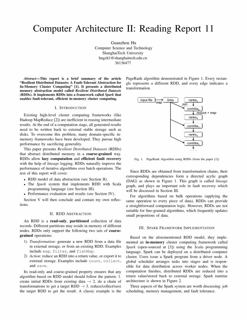
Its read-only and coarse-grained property ensures that anyalgorithm based on RDD model should follow the pattern: 1.create initial RDDs from existing data → 2. do a chain oftransformations to get a target RDD → 3. reduce/collect/savethe target RDD to get the result. A classic example is the
PageRank algorithm demonstrated in Figure 1. Every rectan-gle represents a different RDD, and every edge indicates atransformation.
Fig. 1. PageRank Algorithm using RDDs (from the paper [1])
Since RDDs are obtained from transformation chains, theircorresponding dependencies form a directed acylic graph(DAG) as shown in Figure 1. This graph is called lineagegraph, and plays an important role in fault recovery whichwill be discussed in Section III.
For algorithms based on bulk operations (applying thesame operation to every piece of data), RDDs can providea straightforward computation logic. However, RDDs are notsuitable for fine-grained algorithms, which frequently updatessmall proportions of data.
III. SPARK FRAMEWORK IMPLEMENTATION
Based on the aforementioned RDD model, they imple-mented an in-memory cluster computing framework calledSpark (open-sourced at [3]) using the Scala programminglanguage. Spark can be deployed on a distributed computercluster. Users issue a Spark program from a driver node. Aglobal scheduler arranges tasks into stages and is respon-sible for data distribution across worker nodes. When thecomputation finishes, distributed RDDs are reduced into areturn value/stored back to external storage. Spark runtimearchitecture is shown in Figure 2.
Three aspects of the Spark system are worth discussing: jobscheduling, memory management, and fault tolerance.
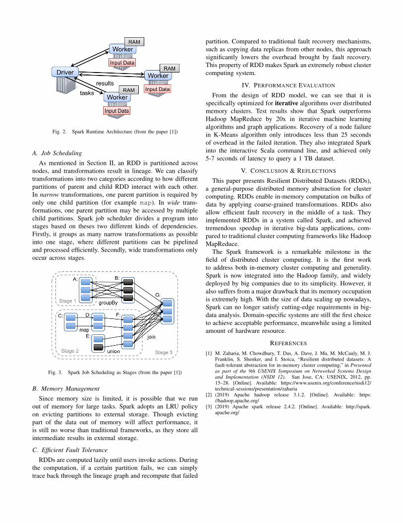
Fig. 2. Spark Runtime Architecture (from the paper [1])
A. Job Scheduling
As mentioned in Section II, an RDD is partitioned acrossnodes, and transformations result in lineage. We can classifytransformations into two categories according to how differentpartitions of parent and child RDD interact with each other.In narrow transformations, one parent partition is required byonly one child partition (for example map). In wide trans-formations, one parent partition may be accessed by multiplechild partitions. Spark job scheduler divides a program intostages based on theses two different kinds of dependencies.Firstly, it groups as many narrow transformations as possibleinto one stage, where different partitions can be pipelinedand processed efficiently. Secondly, wide transformations onlyoccur across stages.
Fig. 3. Spark Job Scheduling as Stages (from the paper [1])
B. Memory Management
Since memory size is limited, it is possible that we runout of memory for large tasks. Spark adopts an LRU policyon evicting partitions to external storage. Though evictingpart of the data out of memory will affect performance, itis still no worse than traditional frameworks, as they store allintermediate results in external storage.
C. Efficient Fault Tolerance
RDDs are computed lazily until users invoke actions. Duringthe computation, if a certain partition fails, we can simplytrace back through the lineage graph and recompute that failed
partition. Compared to traditional fault recovery mechanisms,such as copying data replicas from other nodes, this approachsignificantly lowers the overhead brought by fault recovery.This property of RDD makes Spark an extremely robust clustercomputing system.
IV. PERFORMANCE EVALUATION
From the design of RDD model, we can see that it isspecifically optimized for iterative algorithms over distributedmemory clusters. Test results show that Spark outperformsHadoop MapReduce by 20x in iterative machine learningalgorithms and graph applications. Recovery of a node failurein K-Means algorithm only introduces less than 25 secondsof overhead in the failed iteration. They also integrated Sparkinto the interactive Scala command line, and achieved only5-7 seconds of latency to query a 1 TB dataset.
V. CONCLUSION & REFLECTIONS
This paper presents Resilient Distributed Datasets (RDDs),a general-purpose distributed memory abstraction for clustercomputing. RDDs enable in-memory computation on bulks ofdata by applying coarse-grained transformations. RDDs alsoallow efficient fault recovery in the middle of a task. Theyimplemented RDDs in a system called Spark, and achievedtremendous speedup in iterative big-data applications, com-pared to traditional cluster computing frameworks like HadoopMapReduce.
The Spark framework is a remarkable milestone in thefield of distributed cluster computing. It is the first workto address both in-memory cluster computing and generality.Spark is now integrated into the Hadoop family, and widelydeployed by big companies due to its simplicity. However, italso suffers from a major drawback that its memory occupationis extremely high. With the size of data scaling up nowadays,Spark can no longer satisfy cutting-edge requirements in big-data analysis. Domain-specific systems are still the first choiceto achieve acceptable performance, meanwhile using a limitedamount of hardware resource.
REFERENCES
[1] M. Zaharia, M. Chowdhury, T. Das, A. Dave, J. Ma, M. McCauly, M. J.Franklin, S. Shenker, and I. Stoica, “Resilient distributed datasets: Afault-tolerant abstraction for in-memory cluster computing,” in Presentedas part of the 9th USENIX Symposium on Networked Systems Designand Implementation (NSDI 12). San Jose, CA: USENIX, 2012, pp.15–28. [Online]. Available: https://www.usenix.org/conference/nsdi12/technical-sessions/presentation/zaharia
[2] (2019) Apache hadoop release 3.1.2. [Online]. Available: https://hadoop.apache.org/
[3] (2019) Apache spark release 2.4.2. [Online]. Available: http://spark.apache.org/


![Cse.m-ii-Advances in Computer Architecture [12scs23]-Notes](https://img.pdfslide.net/doc/110x75/55cf989b550346d0339899ef/csem-ii-advances-in-computer-architecture-12scs23-notes.jpg)


![Cse.m-ii-Advances in Computer Architecture [12scs23]-Solution](https://img.pdfslide.net/doc/110x75/577cd0091a28ab9e789138ba/csem-ii-advances-in-computer-architecture-12scs23-solution.jpg)