Embed Size (px)
Citation preview
Database Systems: Conceptual Design IT-Vest 6.9.2008 1
Conceptual Design: Outline• The Data Modelling Process• The Entity-Relationship Model• Mapping Entity-Relationship Model to Tables
Database Systems: Conceptual Design IT-Vest 6.9.2008 2
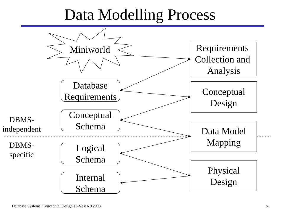
Data Modelling Process
Miniworld Requirements Collection and
Analysis
ConceptualDesign
PhysicalDesign
DatabaseRequirements
ConceptualSchema
LogicalSchema
InternalSchema
Data ModelMappingDBMS-
specific
DBMS-independent
Database Systems: Conceptual Design IT-Vest 6.9.2008 3
Conceptual Design: Outline• The Data Modelling Process• The Entity-Relationship Model
EntitiesAttributesRelationships
Binary/tertiary/n-aryRolesParticipation
KeysWeak Entity Types
• Mapping Entity-Relationship Model to Tables
Database Systems: Conceptual Design IT-Vest 6.9.2008 4
Entity-Relationship Model• The entity-relationship (ER) model is frequently used
as a design model, such as in CASE tools, e.g., Dia and Visio.
• A database can be modelled as:a collection of entities, andrelationships among entities.
• The ER model is used in conceptual design.
• Result of ER modelling is an ER Schema or an ER Diagram.
Database Systems: Conceptual Design IT-Vest 6.9.2008 5
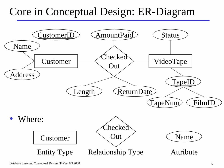
Core in Conceptual Design: ER-Diagram
Name
Customer CheckedOut VideoTape
Name
Address
CustomerID
Length ReturnDate
AmountPaid
TapeID
Status
TapeNum FilmID
CustomerChecked
Out
Relationship Type
• Where:
Entity Type Attribute
Database Systems: Conceptual Design IT-Vest 6.9.2008 6
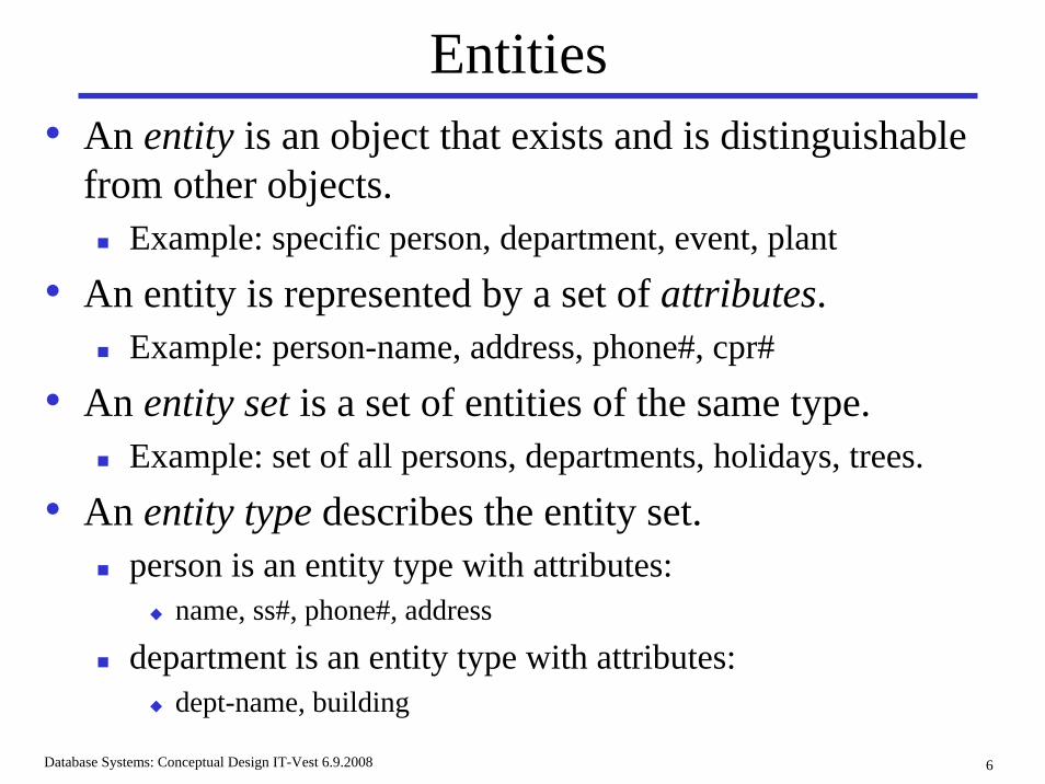
Entities• An entity is an object that exists and is distinguishable
from other objects.Example: specific person, department, event, plant
• An entity is represented by a set of attributes.Example: person-name, address, phone#, cpr#
• An entity set is a set of entities of the same type.Example: set of all persons, departments, holidays, trees.
• An entity type describes the entity set. person is an entity type with attributes:
name, ss#, phone#, address
department is an entity type with attributes:dept-name, building
Database Systems: Conceptual Design IT-Vest 6.9.2008 7
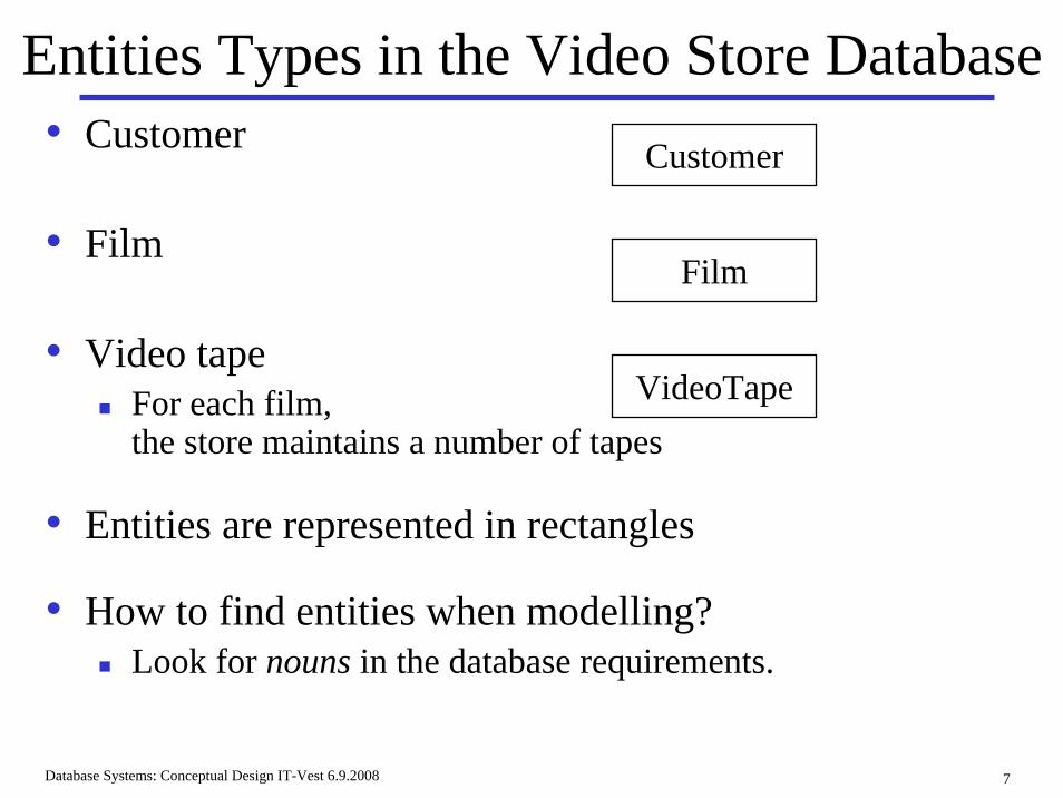
Entities Types in the Video Store Database• Customer
• Film
• Video tapeFor each film, the store maintains a number of tapes
• Entities are represented in rectangles
• How to find entities when modelling?Look for nouns in the database requirements.
Customer
VideoTape
Film
Database Systems: Conceptual Design IT-Vest 6.9.2008 8
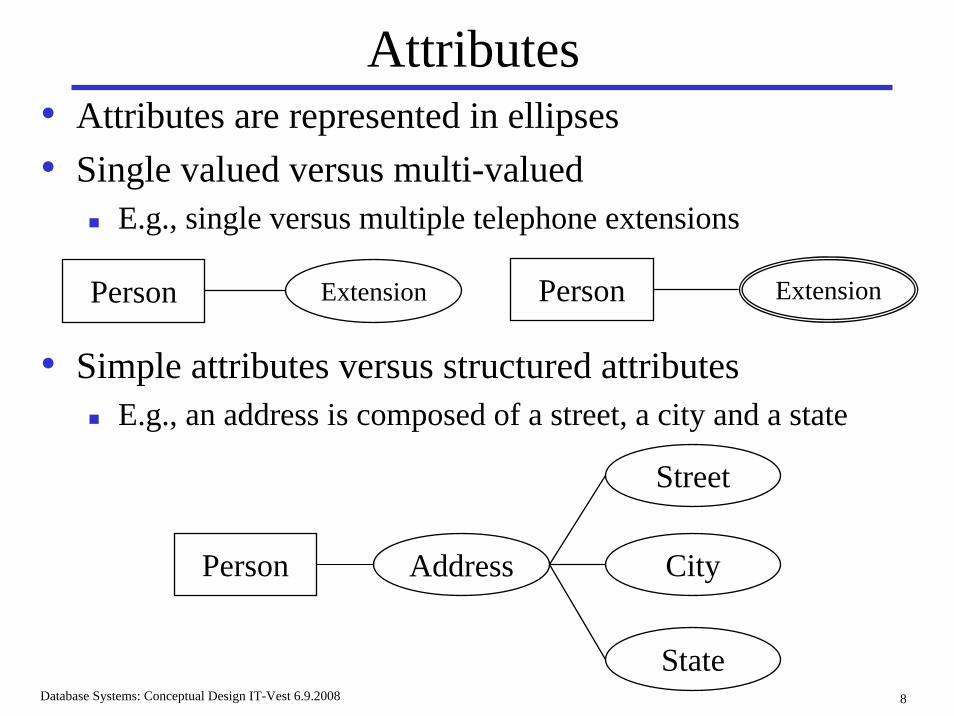
Attributes• Attributes are represented in ellipses• Single valued versus multi-valued
E.g., single versus multiple telephone extensions
Person Extension
• Simple attributes versus structured attributesE.g., an address is composed of a street, a city and a state
Address
Street
City
State
Person
Person Extension
Database Systems: Conceptual Design IT-Vest 6.9.2008 9
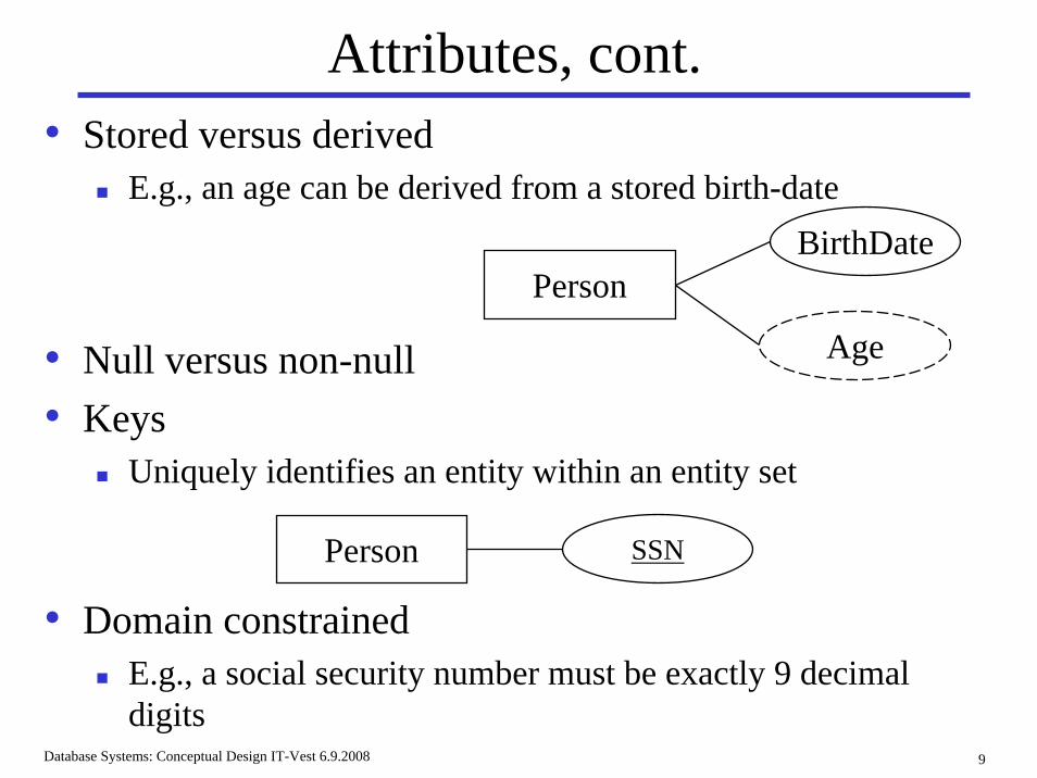
Attributes, cont.• Stored versus derived
E.g., an age can be derived from a stored birth-date
• Null versus non-null• Keys
Uniquely identifies an entity within an entity set
• Domain constrainedE.g., a social security number must be exactly 9 decimal digits
PersonBirthDate
Age
Person SSN
Database Systems: Conceptual Design IT-Vest 6.9.2008 10
Attributes in the Video Store Database• Customers can have names, addresses, customer IDs
(domain constrained to six digits).
• Films can have titles, directors (multi-valued), distributors, and kinds (e.g., foreign film, music video).
• Video tapes can be numbered, and can have a status to indicate whether it is checked out or not.
Database Systems: Conceptual Design IT-Vest 6.9.2008 11
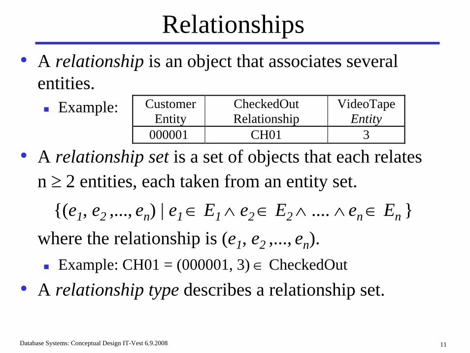
Relationships• A relationship is an object that associates several
entities.Example:
• A relationship set is a set of objects that each relates n ≥ 2 entities, each taken from an entity set.
{(e1, e2 ,..., en) | e1∈ E1∧ e2∈ E2∧ .... ∧ en∈ En }where the relationship is (e1, e2 ,..., en).
Example: CH01 = (000001, 3) ∈ CheckedOut
• A relationship type describes a relationship set.
Customer Entity
CheckedOut Relationship
VideoTape Entity
000001 CH01 3
Database Systems: Conceptual Design IT-Vest 6.9.2008 12
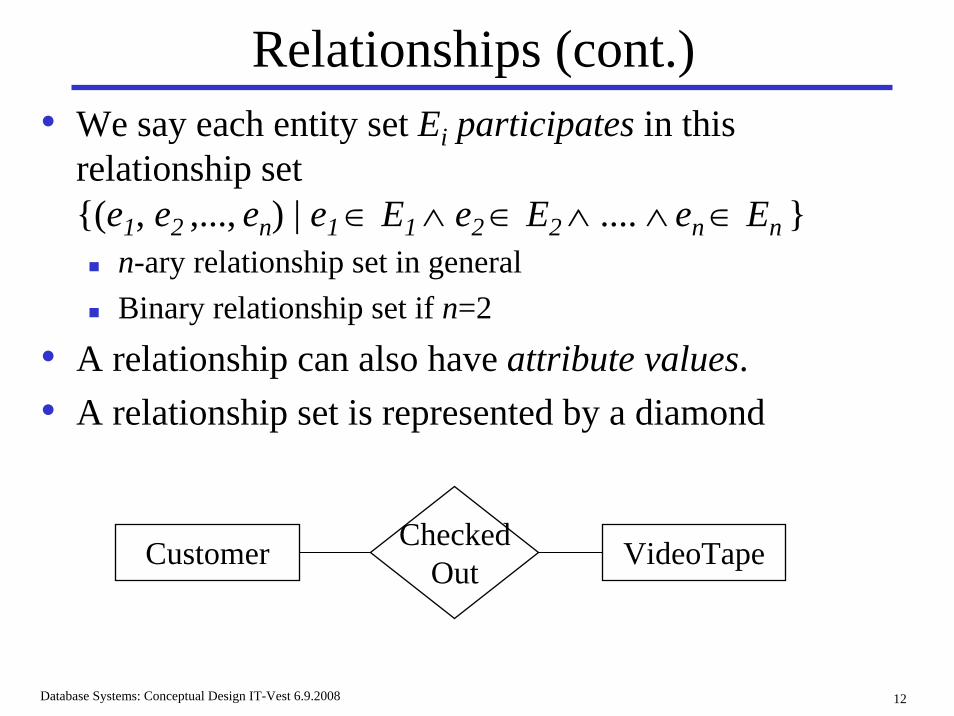
Relationships (cont.)• We say each entity set Ei participates in this
relationship set {(e1, e2 ,..., en) | e1∈ E1∧ e2∈ E2∧ .... ∧ en∈ En }
n-ary relationship set in generalBinary relationship set if n=2
• A relationship can also have attribute values.• A relationship set is represented by a diamond
Customer CheckedOut VideoTape
Database Systems: Conceptual Design IT-Vest 6.9.2008 13
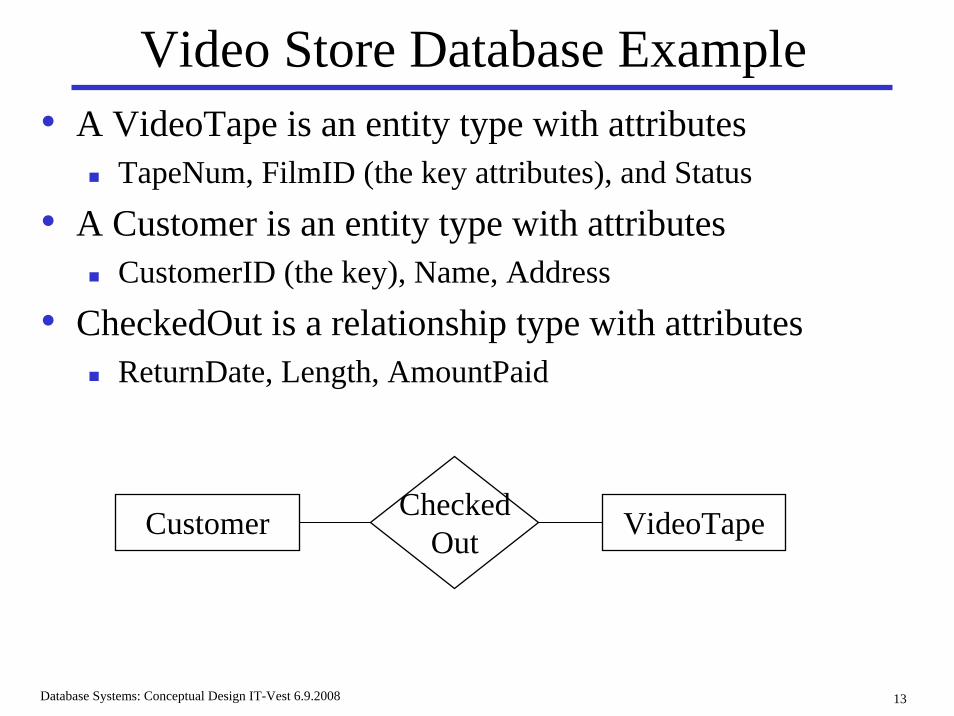
Video Store Database Example• A VideoTape is an entity type with attributes
TapeNum, FilmID (the key attributes), and Status
• A Customer is an entity type with attributesCustomerID (the key), Name, Address
• CheckedOut is a relationship type with attributesReturnDate, Length, AmountPaid
Customer CheckedOut VideoTape
Database Systems: Conceptual Design IT-Vest 6.9.2008 14
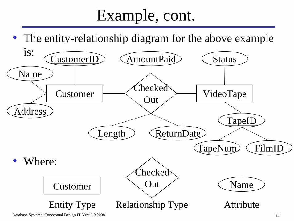
Example, cont.• The entity-relationship diagram for the above example
is:
Name
Customer CheckedOut VideoTape
Name
Address
CustomerID
Length ReturnDate
AmountPaid
TapeID
Status
TapeNum FilmID
CustomerChecked
Out
Relationship Type
• Where:
Entity Type Attribute
Database Systems: Conceptual Design IT-Vest 6.9.2008 15
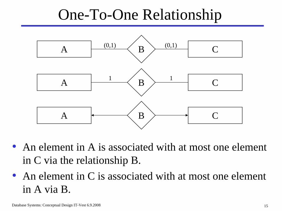
One-To-One Relationship
• An element in A is associated with at most one element in C via the relationship B.
• An element in C is associated with at most one element in A via B.
A B C
A B C
A B C
1 1
(0,1) (0,1)
Database Systems: Conceptual Design IT-Vest 6.9.2008 16
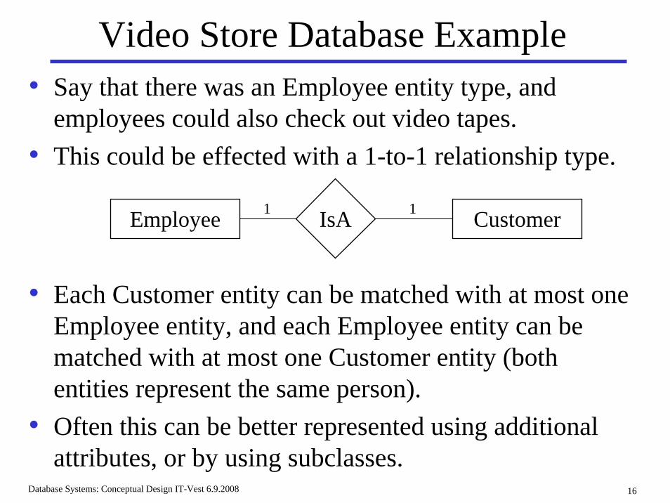
Video Store Database Example• Say that there was an Employee entity type, and
employees could also check out video tapes.• This could be effected with a 1-to-1 relationship type.
• Each Customer entity can be matched with at most one Employee entity, and each Employee entity can be matched with at most one Customer entity (both entities represent the same person).
• Often this can be better represented using additional attributes, or by using subclasses.
Employee IsA Customer1 1
Database Systems: Conceptual Design IT-Vest 6.9.2008 17
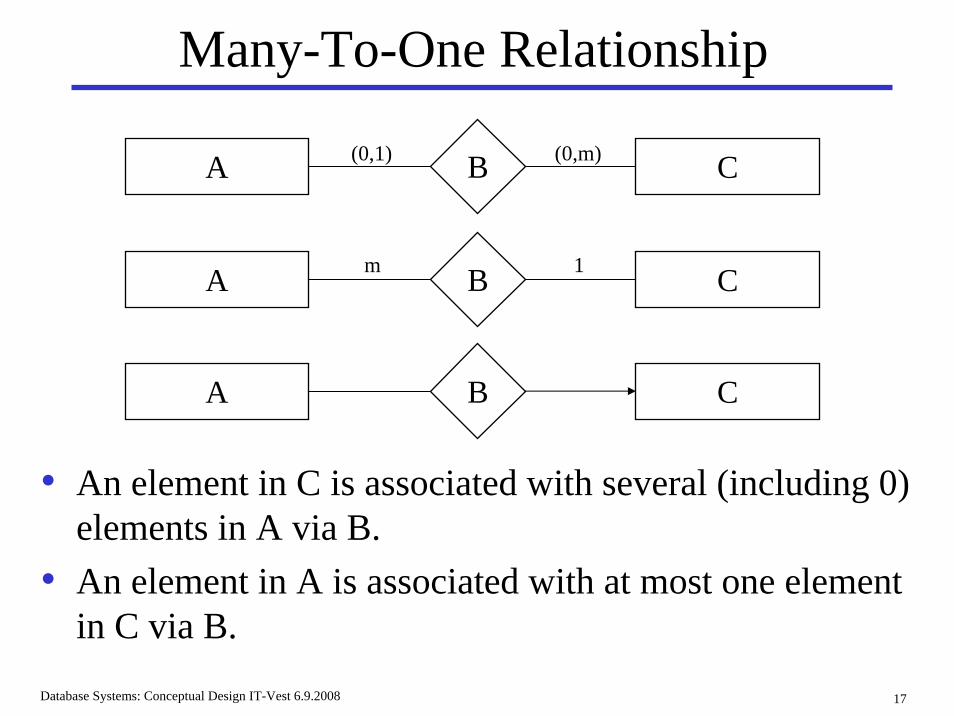
Many-To-One Relationship
• An element in C is associated with several (including 0) elements in A via B.
• An element in A is associated with at most one element in C via B.
A B C
A B C
A B C
m 1
(0,1) (0,m)
Database Systems: Conceptual Design IT-Vest 6.9.2008 18
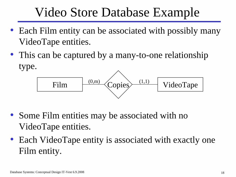
Video Store Database Example• Each Film entity can be associated with possibly many
VideoTape entities.• This can be captured by a many-to-one relationship
type.
• Some Film entities may be associated with no VideoTape entities.
• Each VideoTape entity is associated with exactly one Film entity.
Film Copies VideoTape(0,m) (1,1)
Database Systems: Conceptual Design IT-Vest 6.9.2008 19
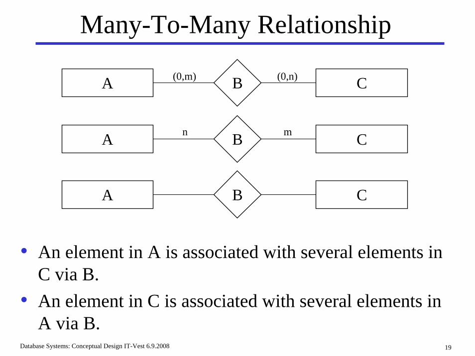
Many-To-Many Relationship
• An element in A is associated with several elements in C via B.
• An element in C is associated with several elements in A via B.
A B C
A B C
A B C
n m
(0,m) (0,n)
Database Systems: Conceptual Design IT-Vest 6.9.2008 20
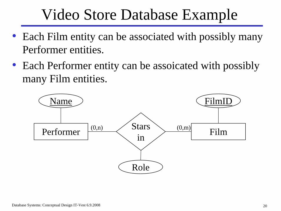
Video Store Database Example
Performer Film(0,n) (0,m)Starsin
Name FilmID
Role
• Each Film entity can be associated with possibly many Performer entities.
• Each Performer entity can be assoicated with possibly many Film entities.
Database Systems: Conceptual Design IT-Vest 6.9.2008 21
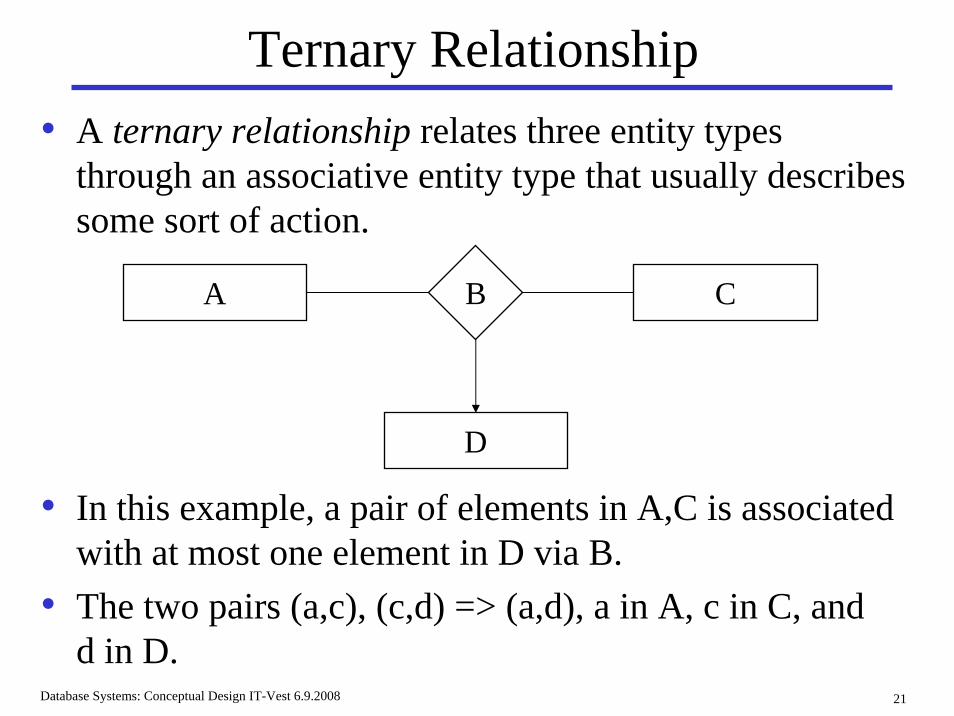
Ternary Relationship
• In this example, a pair of elements in A,C is associated with at most one element in D via B.
• The two pairs (a,c), (c,d) => (a,d), a in A, c in C, andd in D.
A B C
D
• A ternary relationship relates three entity types through an associative entity type that usually describes some sort of action.
Database Systems: Conceptual Design IT-Vest 6.9.2008 22
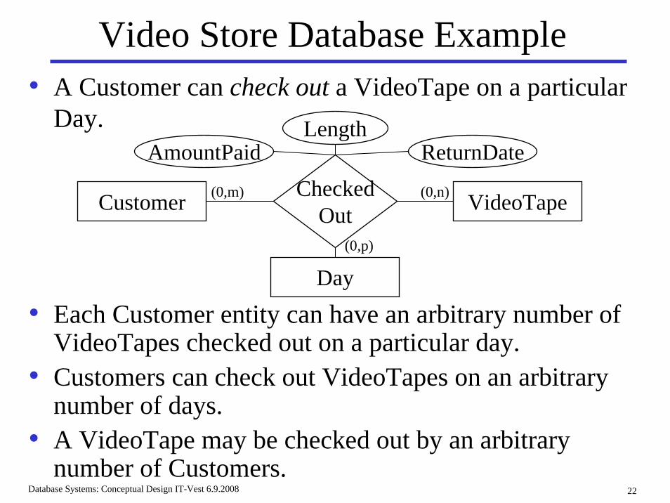
Video Store Database Example• A Customer can check out a VideoTape on a particular
Day.
• Each Customer entity can have an arbitrary number of VideoTapes checked out on a particular day.
• Customers can check out VideoTapes on an arbitrary number of days.
• A VideoTape may be checked out by an arbitrary number of Customers.
Customer VideoTape(0,m) (0,n)CheckedOut
Day(0,p)
LengthReturnDateAmountPaid
Database Systems: Conceptual Design IT-Vest 6.9.2008 23
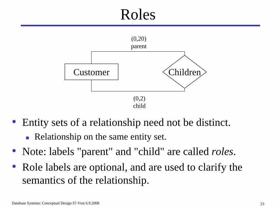
Roles
• Entity sets of a relationship need not be distinct.Relationship on the same entity set.
• Note: labels "parent" and "child" are called roles.• Role labels are optional, and are used to clarify the
semantics of the relationship.
ChildrenCustomer
(0,20)parent
(0,2)child
Database Systems: Conceptual Design IT-Vest 6.9.2008 24
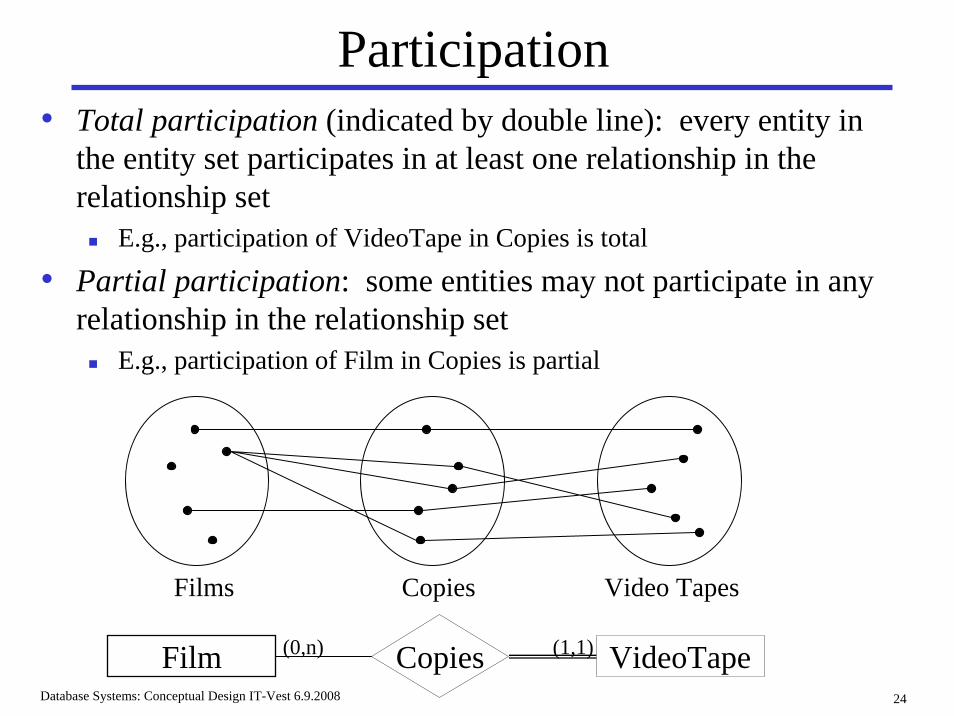
Participation
Films Copies Video Tapes
Film VideoTape(0,n) (1,1)Copies
• Total participation (indicated by double line): every entity in the entity set participates in at least one relationship in the relationship set
E.g., participation of VideoTape in Copies is total
• Partial participation: some entities may not participate in any relationship in the relationship set
E.g., participation of Film in Copies is partial
Database Systems: Conceptual Design IT-Vest 6.9.2008 25
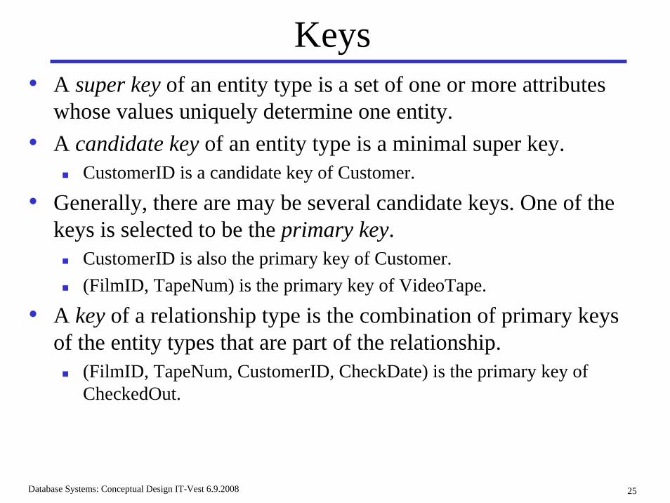
Keys• A super key of an entity type is a set of one or more attributes
whose values uniquely determine one entity.• A candidate key of an entity type is a minimal super key.
CustomerID is a candidate key of Customer.
• Generally, there are may be several candidate keys. One of the keys is selected to be the primary key.
CustomerID is also the primary key of Customer.(FilmID, TapeNum) is the primary key of VideoTape.
• A key of a relationship type is the combination of primary keys of the entity types that are part of the relationship.
(FilmID, TapeNum, CustomerID, CheckDate) is the primary key of CheckedOut.
Database Systems: Conceptual Design IT-Vest 6.9.2008 26
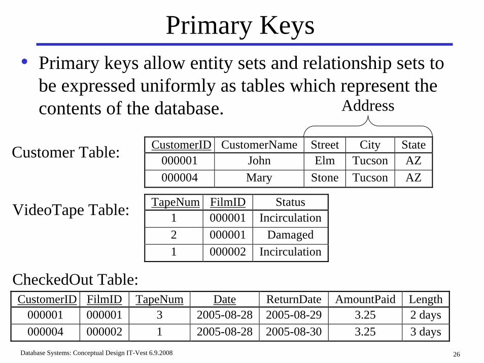
Primary Keys• Primary keys allow entity sets and relationship sets to
be expressed uniformly as tables which represent the contents of the database.
CustomerID CustomerName Street City State000001 John Elm Tucson AZ000004 Mary Stone Tucson AZ
Address
TapeNum FilmID Status1 000001 Incirculation2 000001 Damaged1 000002 Incirculation
CustomerID FilmID TapeNum Date ReturnDate AmountPaid Length 000001 000001 3 2005-08-28 2005-08-29 3.25 2 days 000004 000002 1 2005-08-28 2005-08-30 3.25 3 days
Customer Table:
CheckedOut Table:
VideoTape Table:
Database Systems: Conceptual Design IT-Vest 6.9.2008 27
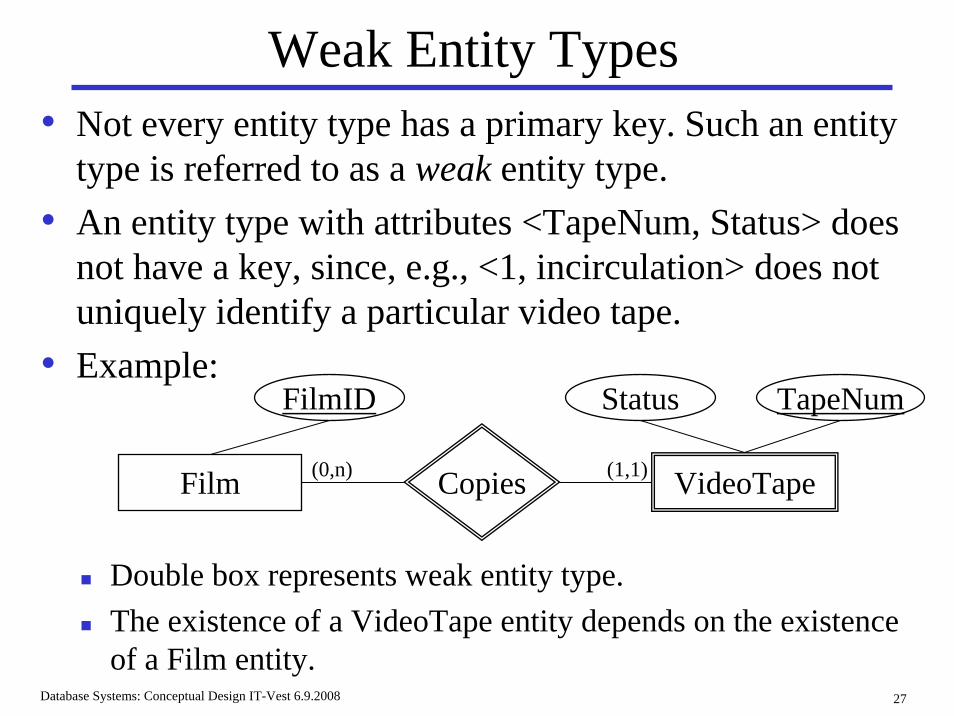
Weak Entity Types• Not every entity type has a primary key. Such an entity
type is referred to as a weak entity type.• An entity type with attributes <TapeNum, Status> does
not have a key, since, e.g., <1, incirculation> does not uniquely identify a particular video tape.
• Example:
Double box represents weak entity type.The existence of a VideoTape entity depends on the existence of a Film entity.
Film VideoTape(0,n) (1,1)Copies
Status TapeNumFilmID
Database Systems: Conceptual Design IT-Vest 6.9.2008 28
Weak Entity Types, cont.• Semantics:
Deletion of a Film entity requires deletion of that film's videotape entities.
• A weak entity can be related to precisely one strong entity in an entity type, via a 1-1 or 1-n relationship.
• It is of course possible to introduce more attributes to the video tape entity type, so that a primary key will exist, but they may not be needed for database processing.
Database Systems: Conceptual Design IT-Vest 6.9.2008 29
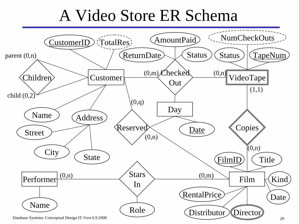
A Video Store ER Schema
Customer CheckedOut VideoTape
Status
Film
Copies
Performer StarsIn
Children
Reserved
Day
TapeNum
NumCheckOutsAmountPaid
ReturnDate Status
Title
Address
Street
City State
CustomerID TotalRes
Name
Date
RoleName
FilmID
RentalPrice
Distributor
Kind
Date
Director
parent (0,n)
child (0,2)
(0,m) (0,n)
(1,1)
(0,n)
(0,n)
(0,n) (0,m)
(0,q)
Database Systems: Conceptual Design IT-Vest 6.9.2008 30
Design Notes• Entities are nouns, relationships are verbs.
• Each statement in the requirement specification should be located somewhere in the ER schema.
• Each ER schema construct should be located somewhere in the requirement specification.
• Conceptual design often reveals inconsistencies and ambiguities in the requirement specification, which must be first resolved.
Database Systems: Conceptual Design IT-Vest 6.9.2008 31
Review of ER-Model• Basic ER model has entities, relationships, and
attributes.• Extended ER model adds subclasses and superclasses.
Also a concept called categories, not dicussed here .• The ER is used extensively.• The notation used various ER modeling tools differs.
Database Systems: Conceptual Design IT-Vest 6.9.2008 32
Conceptual Design: Outline• The Data Modelling Process• The Entity-Relationship Model• Mapping Entity-Relationship Model to Tables
7 out of a total 9 steps
Database Systems: Conceptual Design IT-Vest 6.9.2008 33
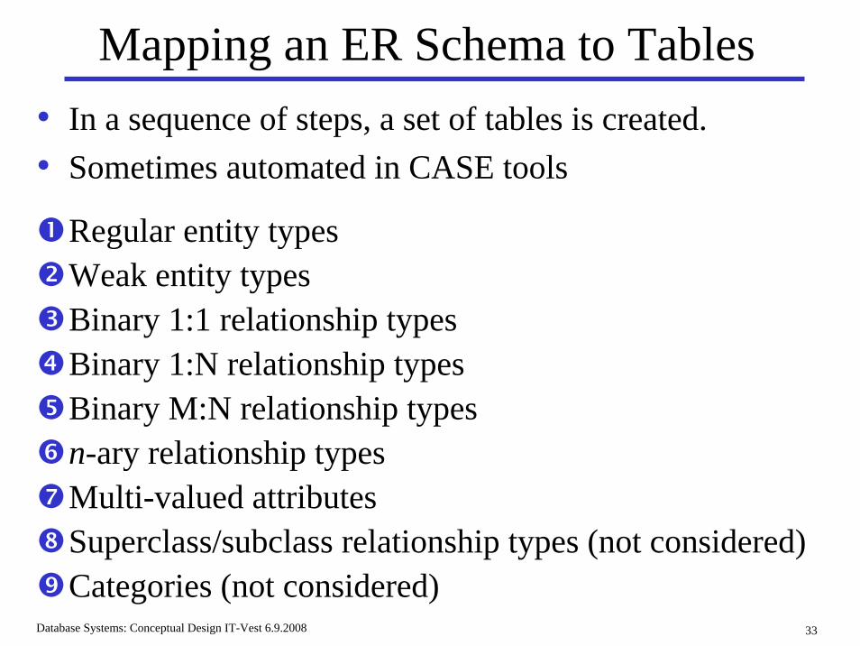
Mapping an ER Schema to Tables
Regular entity typesWeak entity typesBinary 1:1 relationship typesBinary 1:N relationship typesBinary M:N relationship typesn-ary relationship typesMulti-valued attributesSuperclass/subclass relationship types (not considered)Categories (not considered)
• In a sequence of steps, a set of tables is created.• Sometimes automated in CASE tools
Database Systems: Conceptual Design IT-Vest 6.9.2008 34
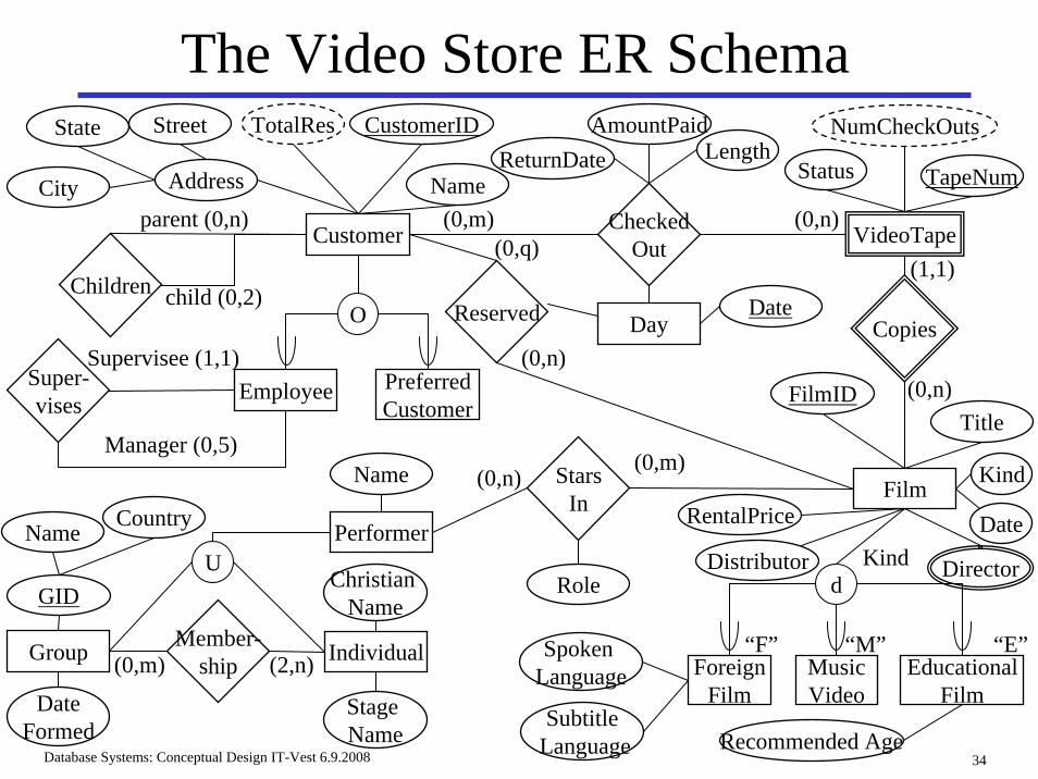
The Video Store ER Schema
Customer CheckedOut VideoTape
Status
Film
Copies
Performer
StarsIn
ChildrenReserved Day
TapeNum
NumCheckOutsAmountPaidReturnDate Length
Title
Address
Street
City
State CustomerIDTotalRes
Name
Date
Role
Name
FilmID
RentalPrice
Distributor
Kind
Date
Director
parent (0,n)
child (0,2)
(0,m) (0,n)
(1,1)
(0,n)(0,n)
(0,n)(0,m)
(0,q)
O
Employee PreferredCustomer
Super-vises
Supervisee (1,1)
Manager (0,5)
Group Individual(0,m) (2,n)Member-
ship
UGID
Stage Name
Christian Name
DateFormed
CountryName
d
ForeignFilm
EducationalFilm
MusicVideo
Spoken Language
SubtitleLanguage Recommended Age
“F” “M” “E”
Kind
Database Systems: Conceptual Design IT-Vest 6.9.2008 35
ER To Tables: Step 1• Create a table for each regular entity type.• The table has one column for each simple attribute of
its corresponding entity type. • The primary key for the table is the primary key of the
entity type.• If there are no attributes other than the primary key,
and if the entity participates totally in a relationship, then the table can be eliminated.
Database Systems: Conceptual Design IT-Vest 6.9.2008 36
ER To Tables: Step 1, Example
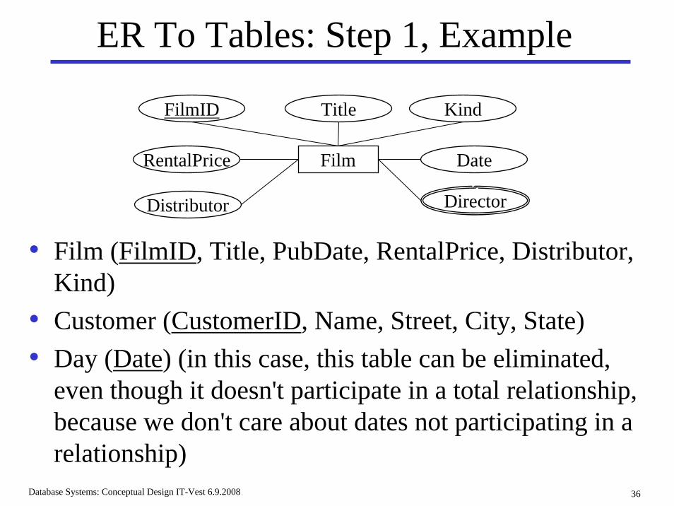
• Film (FilmID, Title, PubDate, RentalPrice, Distributor, Kind)
• Customer (CustomerID, Name, Street, City, State)• Day (Date) (in this case, this table can be eliminated,
even though it doesn't participate in a total relationship, because we don't care about dates not participating in a relationship)
Film
TitleFilmID
RentalPrice
Distributor
Kind
Date
Director
Database Systems: Conceptual Design IT-Vest 6.9.2008 37
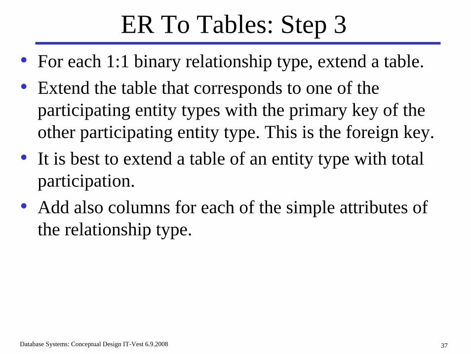
ER To Tables: Step 3• For each 1:1 binary relationship type, extend a table.• Extend the table that corresponds to one of the
participating entity types with the primary key of the other participating entity type. This is the foreign key.
• It is best to extend a table of an entity type with total participation.
• Add also columns for each of the simple attributes of the relationship type.
Database Systems: Conceptual Design IT-Vest 6.9.2008 38
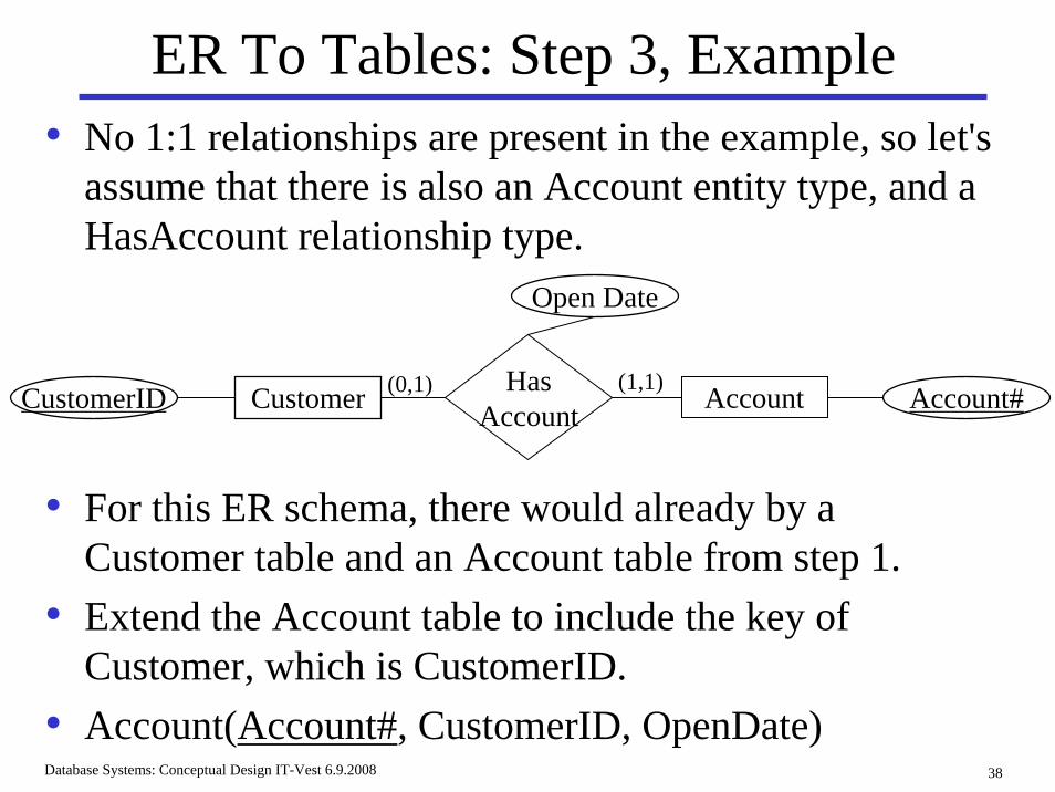
ER To Tables: Step 3, Example• No 1:1 relationships are present in the example, so let's
assume that there is also an Account entity type, and a HasAccount relationship type.
• For this ER schema, there would already by a Customer table and an Account table from step 1.
• Extend the Account table to include the key of Customer, which is CustomerID.
• Account(Account#, CustomerID, OpenDate)
AccountCustomer HasAccount
Open Date
CustomerID (1,1)(0,1) Account#
Database Systems: Conceptual Design IT-Vest 6.9.2008 39
ER To Tables: Step 4• For each regular 1:N binary relationship type, there are
several approaches.Option 1: If the relationship is total, then extend a table.
Option 2: If the relationship is not total, extend the table with nullable attributes (sometimes not allowed for foreign keys).
Option 3: Create a separate table for the relationship.
Database Systems: Conceptual Design IT-Vest 6.9.2008 40
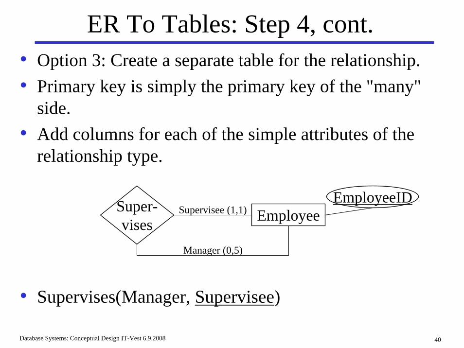
ER To Tables: Step 4, cont.• Option 3: Create a separate table for the relationship.• Primary key is simply the primary key of the "many"
side. • Add columns for each of the simple attributes of the
relationship type.
EmployeeSuper-vises
Supervisee (1,1)
Manager (0,5)
EmployeeID
• Supervises(Manager, Supervisee)
Database Systems: Conceptual Design IT-Vest 6.9.2008 41
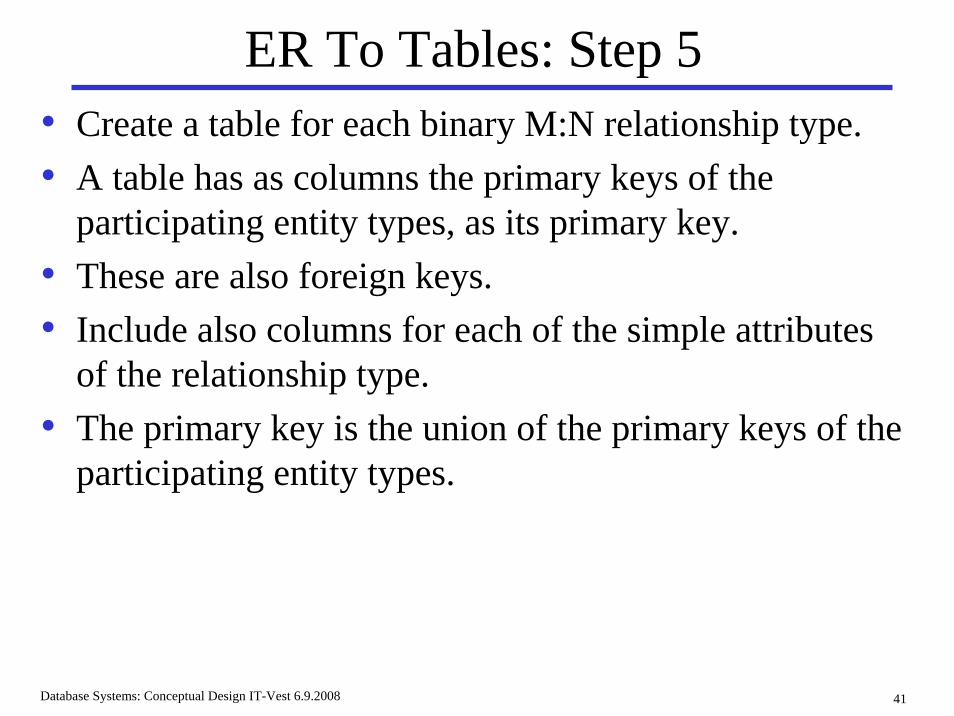
ER To Tables: Step 5• Create a table for each binary M:N relationship type.• A table has as columns the primary keys of the
participating entity types, as its primary key.• These are also foreign keys.• Include also columns for each of the simple attributes
of the relationship type.• The primary key is the union of the primary keys of the
participating entity types.
Database Systems: Conceptual Design IT-Vest 6.9.2008 42
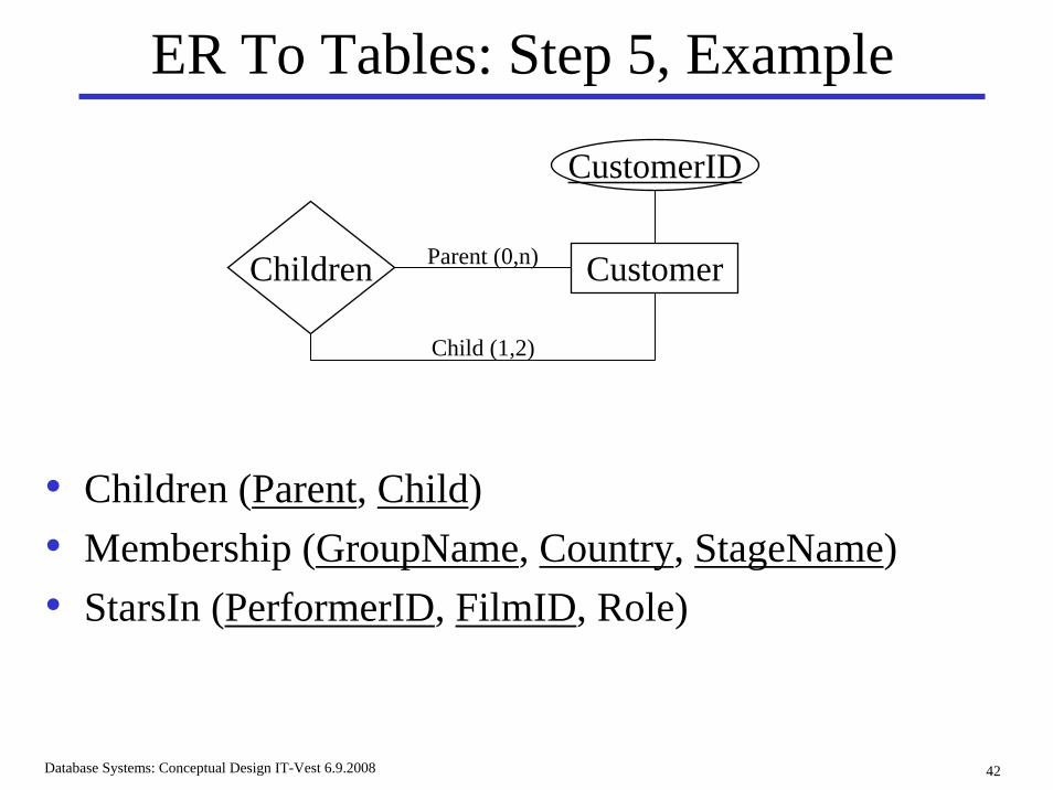
ER To Tables: Step 5, Example
• Children (Parent, Child)• Membership (GroupName, Country, StageName)• StarsIn (PerformerID, FilmID, Role)
CustomerChildren Parent (0,n)
Child (1,2)
CustomerID
Database Systems: Conceptual Design IT-Vest 6.9.2008 43
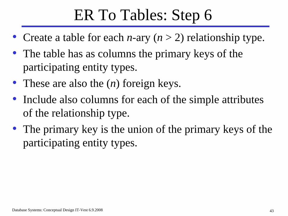
ER To Tables: Step 6• Create a table for each n-ary (n > 2) relationship type.• The table has as columns the primary keys of the
participating entity types.• These are also the (n) foreign keys.• Include also columns for each of the simple attributes
of the relationship type.• The primary key is the union of the primary keys of the
participating entity types.
Database Systems: Conceptual Design IT-Vest 6.9.2008 44
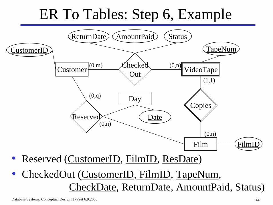
ER To Tables: Step 6, Example
• Reserved (CustomerID, FilmID, ResDate)• CheckedOut (CustomerID, FilmID, TapeNum,
CheckDate, ReturnDate, AmountPaid, Status)
Customer CheckedOut VideoTape
Film
CopiesReserved
Day
TapeNum
AmountPaidReturnDate Status
CustomerID
Date
FilmID
(0,m) (0,n)
(1,1)
(0,n)
(0,n)
(0,q)
Database Systems: Conceptual Design IT-Vest 6.9.2008 45
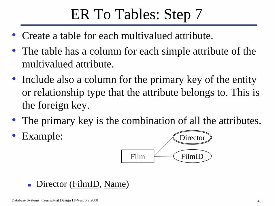
ER To Tables: Step 7• Create a table for each multivalued attribute.• The table has a column for each simple attribute of the
multivalued attribute.• Include also a column for the primary key of the entity
or relationship type that the attribute belongs to. This is the foreign key.
• The primary key is the combination of all the attributes.• Example:
Director (FilmID, Name)
Film FilmID
Director
Database Systems: Conceptual Design IT-Vest 6.9.2008 46
General Discussion• Note that derived attributes and composite attributes
are not explicitly included.• Different options may be used for a multilevel
specialization hierarchy.• Superclasses that share a subclass have the same key,
and all options are applicable.• The resulting tables do not differentiate entity and
relationship types.
Database Systems: Conceptual Design IT-Vest 6.9.2008 47
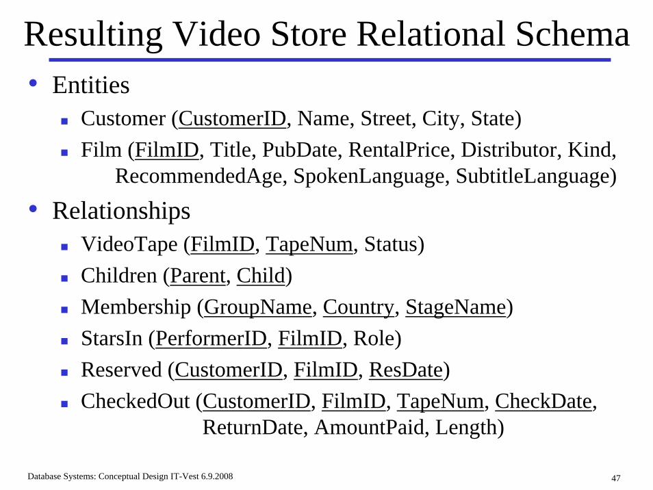
Resulting Video Store Relational Schema• Entities
Customer (CustomerID, Name, Street, City, State)Film (FilmID, Title, PubDate, RentalPrice, Distributor, Kind,
RecommendedAge, SpokenLanguage, SubtitleLanguage)
• RelationshipsVideoTape (FilmID, TapeNum, Status)Children (Parent, Child)Membership (GroupName, Country, StageName)StarsIn (PerformerID, FilmID, Role)Reserved (CustomerID, FilmID, ResDate)CheckedOut (CustomerID, FilmID, TapeNum, CheckDate,
ReturnDate, AmountPaid, Length)
Database Systems: Conceptual Design IT-Vest 6.9.2008 48
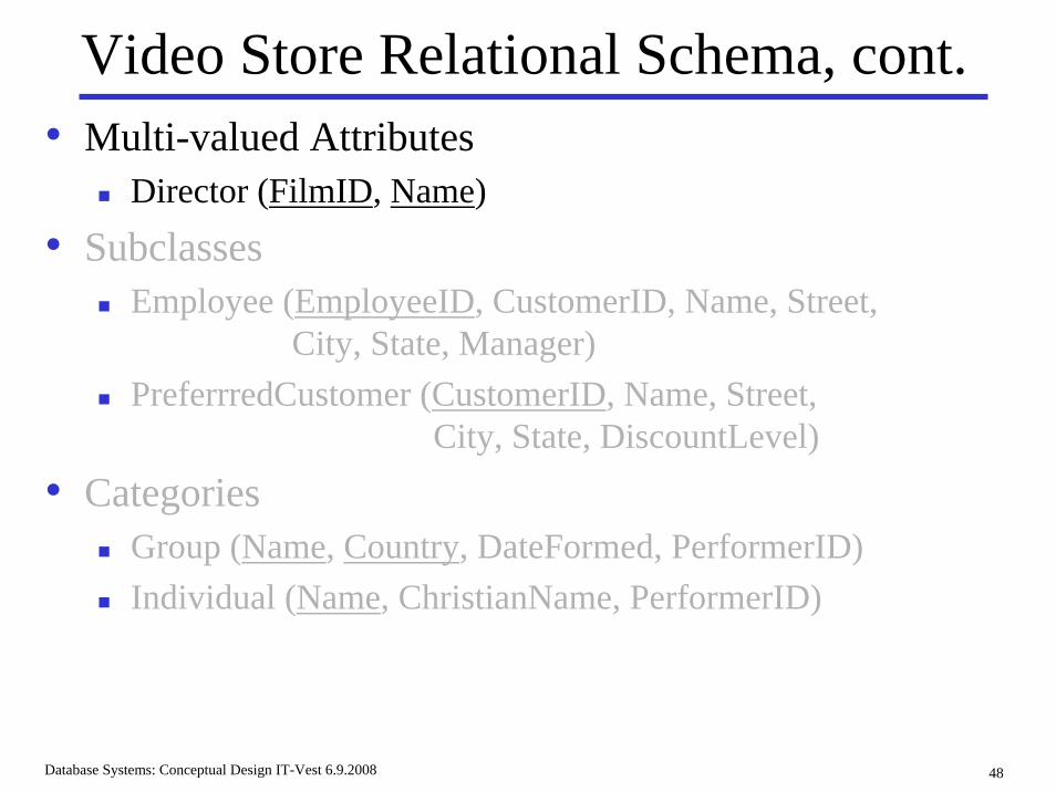
Video Store Relational Schema, cont.• Multi-valued Attributes
Director (FilmID, Name)
• SubclassesEmployee (EmployeeID, CustomerID, Name, Street,
City, State, Manager)PreferrredCustomer (CustomerID, Name, Street,
City, State, DiscountLevel)
• CategoriesGroup (Name, Country, DateFormed, PerformerID)Individual (Name, ChristianName, PerformerID)
Database Systems: Conceptual Design IT-Vest 6.9.2008 49
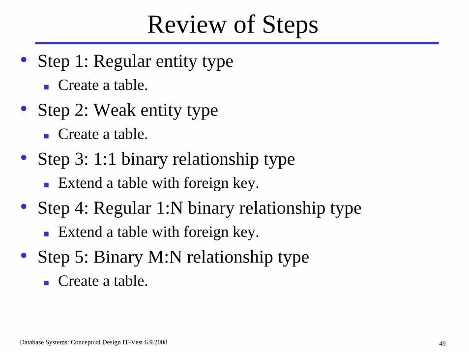
Review of Steps• Step 1: Regular entity type
Create a table.
• Step 2: Weak entity typeCreate a table.
• Step 3: 1:1 binary relationship typeExtend a table with foreign key.
• Step 4: Regular 1:N binary relationship typeExtend a table with foreign key.
• Step 5: Binary M:N relationship typeCreate a table.
Database Systems: Conceptual Design IT-Vest 6.9.2008 50
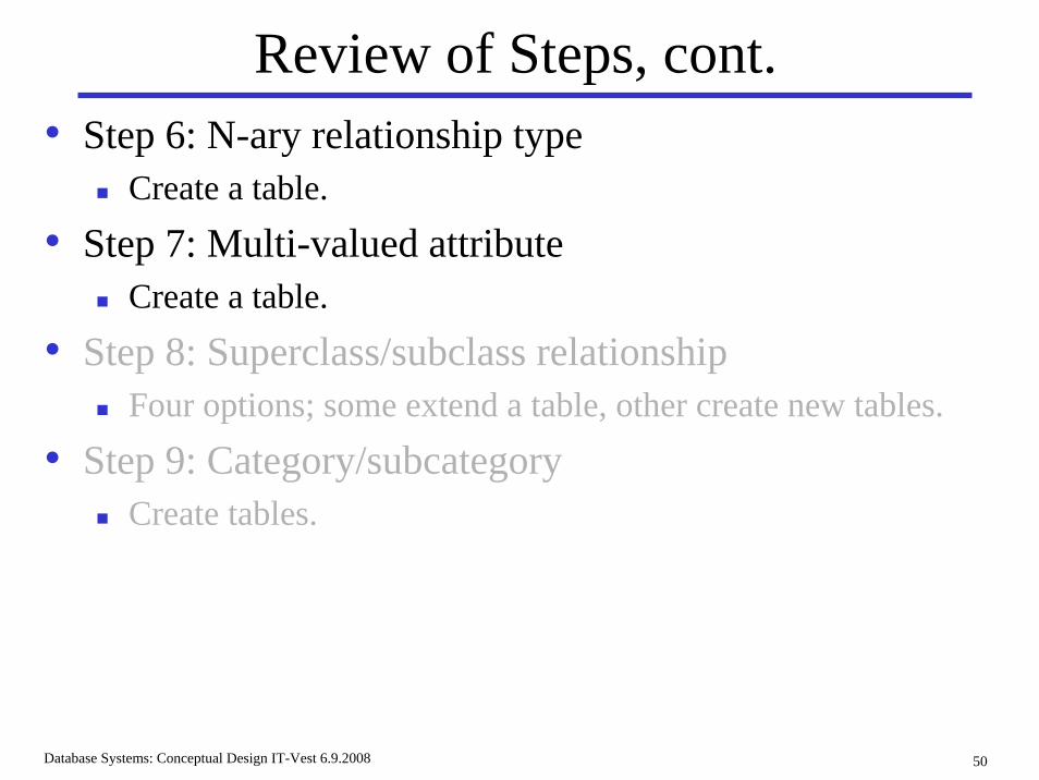
Review of Steps, cont.• Step 6: N-ary relationship type
Create a table.
• Step 7: Multi-valued attributeCreate a table.
• Step 8: Superclass/subclass relationshipFour options; some extend a table, other create new tables.
• Step 9: Category/subcategoryCreate tables.