Embed Size (px)
Citation preview
Send document comments to nexus1k -docfeedback@c i sco .com.
Cisco Nexus Virtual Services Appliance SOL-27730-01
C H A P T E R 3
Configuring the Network UplinksThis chapter describes how to configure the uplink type and includes the following sections:
• Information About Network Uplink Configurations, page 3-1
• Guidelines and Limitations, page 3-4
• Configuring Network Uplink Types, page 3-5
• Assigning a Native VLAN to a Port Channel, page 3-15
• Shutting Down Ports or Port Channel Interfaces, page 3-16
• Verifying the Uplink Configuration, page 3-18
• Additional References, page 3-21
• Feature History for Uplink, page 3-22
Information About Network Uplink ConfigurationsCisco Nexus Virtual Services Appliance product family supports two types of network uplink configurations to connect to the network:
• Flexible Network Uplink Configuration, page 3-1
• Static Network Uplink Configuration, page 3-4
Flexible Network Uplink ConfigurationFlexible network configuration offers complete flexibility to connect Cisco Nexus Virtual Services Appliance to the network, thus enabling appropriate traffic segregation policies like VSB traffic segregation.
This configuration consists of the following features:
• Complete flexibility in terms of port configuration and usage
• Flexible building of ports into a port channel.
• Flexible assignment of a port or port channel to a VSB interface.
• Easy uplink configuration.
• Ability to achieve maximum uplink.
3-1oftware Configuration Guide, Release 4.2(1)SP1(5.1)
Send document comments to nexus1k -doc feedback@c i sco .com.
Chapter 3 Configuring the Network Uplinks Information About Network Uplink Configurations
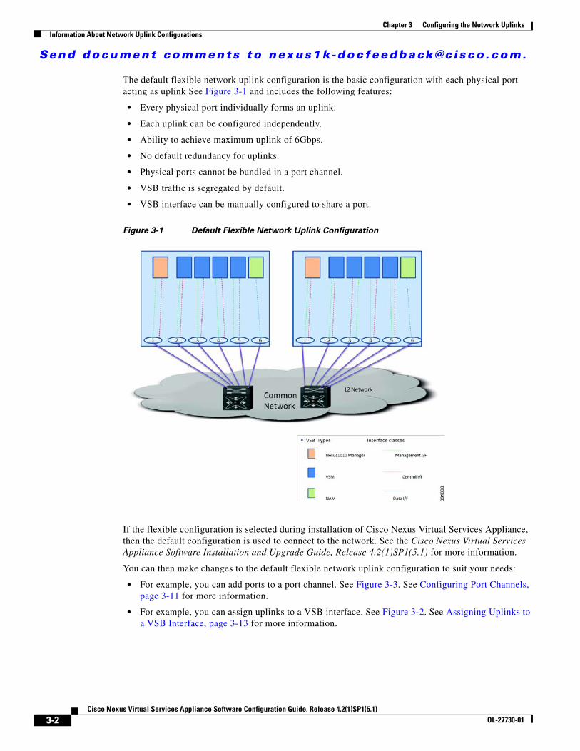
The default flexible network uplink configuration is the basic configuration with each physical port acting as uplink See Figure 3-1 and includes the following features:
• Every physical port individually forms an uplink.
• Each uplink can be configured independently.
• Ability to achieve maximum uplink of 6Gbps.
• No default redundancy for uplinks.
• Physical ports cannot be bundled in a port channel.
• VSB traffic is segregated by default.
• VSB interface can be manually configured to share a port.
Figure 3-1 Default Flexible Network Uplink Configuration
If the flexible configuration is selected during installation of Cisco Nexus Virtual Services Appliance, then the default configuration is used to connect to the network. See the Cisco Nexus Virtual Services Appliance Software Installation and Upgrade Guide, Release 4.2(1)SP1(5.1) for more information.
You can then make changes to the default flexible network uplink configuration to suit your needs:
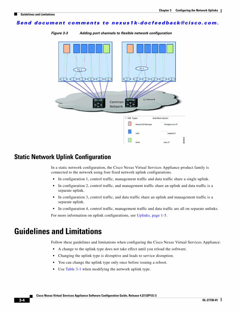
• For example, you can add ports to a port channel. See Figure 3-3. See Configuring Port Channels, page 3-11 for more information.
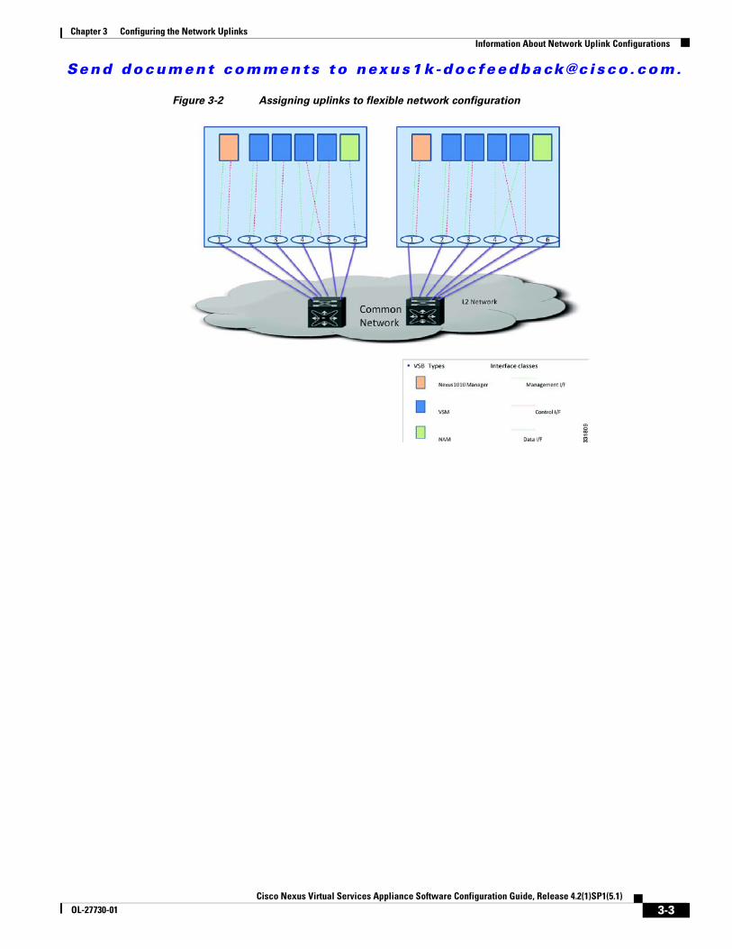
• For example, you can assign uplinks to a VSB interface. See Figure 3-2. See Assigning Uplinks to a VSB Interface, page 3-13 for more information.
3-2Cisco Nexus Virtual Services Appliance Software Configuration Guide, Release 4.2(1)SP1(5.1)
OL-27730-01
Send document comments to nexus1k -doc feedback@c i sco .com.
Chapter 3 Configuring the Network UplinksInformation About Network Uplink Configurations
Figure 3-2 Assigning uplinks to flexible network configuration
3-3Cisco Nexus Virtual Services Appliance Software Configuration Guide, Release 4.2(1)SP1(5.1)
OL-27730-01
Send document comments to nexus1k -doc feedback@c i sco .com.
Chapter 3 Configuring the Network Uplinks Guidelines and Limitations
Figure 3-3 Adding port channels to flexible network configuration
Static Network Uplink ConfigurationIn a static network configuration, the Cisco Nexus Virtual Services Appliance product family is connected to the network using four fixed network uplink configurations.
• In configuration 1, control traffic, management traffic and data traffic share a single uplink.
• In configuration 2, control traffic, and management traffic share an uplink and data traffic is a separate uplink.
• In configuration 3, control traffic, and data traffic share an uplink and management traffic is a separate uplink.
• In configuration 4, control traffic, management traffic and data traffic are all on separate unlinks.
For more information on uplink configurations, see Uplinks, page 1-5.
Guidelines and LimitationsFollow these guidelines and limitations when configuring the Cisco Nexus Virtual Services Appliance:
• A change to the uplink type does not take effect until you reload the software.
• Changing the uplink type is disruptive and leads to service disruption.
• You can change the uplink type only once before issuing a reboot.
• Use Table 3-1 when modifying the network uplink type.
3-4Cisco Nexus Virtual Services Appliance Software Configuration Guide, Release 4.2(1)SP1(5.1)
OL-27730-01
Send document comments to nexus1k -doc feedback@c i sco .com.
Chapter 3 Configuring the Network UplinksGuidelines and Limitations
Table 3-1 Uplink Usage
Uplink Type Usage
1 When only the Cisco Nexus 1000V VSM is installed.
2 When only NAM is installed.
3 When the management and data traffic upstream must be separated.
4 When the management and data traffic upstream must be separated and control and data traffic must also be separated.
5 Flexible network uplink
Configuring Network Uplink TypesThis section includes the following topics:
• Modifying the Uplink Type, page 3-5
• Migrating from Static Network Uplink to Flexible Network Uplink, page 3-7
• Migrating From Flexible Network Uplink to Static Network Uplink, page 3-9
• Configuring Port Channels, page 3-11
• Deleting Port Channels, page 3-12
• Assigning Uplinks to a VSB Interface, page 3-13
Modifying the Uplink Type Use this procedure to modify the uplink type on an operational Cisco Nexus Virtual Services Appliance.
BEFORE YOU BEGIN
Before beginning this procedure, you must know or do the following:
• You are logged in to the CLI in EXEC mode.
• You must reload the Cisco Nexus Virtual Services Appliance pair in order to activate the changes made in this procedure. This procedure includes a step for reloading.
Caution To prevent loss of connectivity, you must reconfigure the uplink switches to correspond with the change made in this procedure.
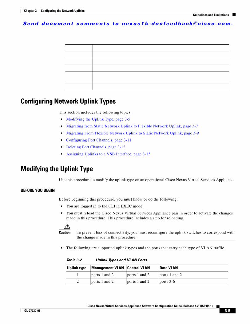
• The following are supported uplink types and the ports that carry each type of VLAN traffic.
Table 3-2 Uplink Types and VLAN Ports
Uplink type Management VLAN Control VLAN Data VLAN
1 ports 1 and 2 ports 1 and 2 ports 1 and 2
2 ports 1 and 2 ports 1 and 2 ports 3-6
3-5Cisco Nexus Virtual Services Appliance Software Configuration Guide, Release 4.2(1)SP1(5.1)
OL-27730-01

Send document comments to nexus1k -doc feedback@c i sco .com.
Chapter 3 Configuring the Network Uplinks Guidelines and Limitations
• For a description of each uplink, see the “Uplinks” section on page 1-5.
SUMMARY STEPS
1. config terminal
2. network uplink type number
3. show network-uplink type
4. copy running-config startup-config
5. reload
DETAILED STEPS
Command Purpose
Step 1 config t
Example:switch# config terminalswitch(config)#
Places you in the CLI Global Configuration mode.
Step 2 network uplink type number
Example:switch(config)# network uplink type 2switch(config)#
Changes the uplink type for the Cisco Nexus Virtual Services Appliance.
number: 1, 2, 3, or 4
Step 3 show network-uplink type
Example:switch(config)# show network uplink typeAdministrative topology id: 2Operational topology id: 1switch(config)#
Displays the uplink configuration for verification.
Step 4 copy running-config startup-config
Example:switch(config)# copy running-config startup-config
Saves the running configuration persistently through reboots and restarts by copying it to the startup configuration.
Step 5 reload
Example:switch(config)# reload
This command will reboot the system. (y/n)? [n] y2009 Oct 30 21:51:34 s1 %$ VDC-1 %$ %PLATFORM-2-PFM_SYSTEM_RESET: Manual system restart from Command Line Interface
switch(config)#
3 ports 1 and 2 ports 3-6 ports 3-6
4 ports 1 and 2 ports 3-4 ports 5-6
Table 3-2 Uplink Types and VLAN Ports (continued)
Uplink type Management VLAN Control VLAN Data VLAN
3-6Cisco Nexus Virtual Services Appliance Software Configuration Guide, Release 4.2(1)SP1(5.1)
OL-27730-01
Send document comments to nexus1k -doc feedback@c i sco .com.
Chapter 3 Configuring the Network UplinksGuidelines and Limitations
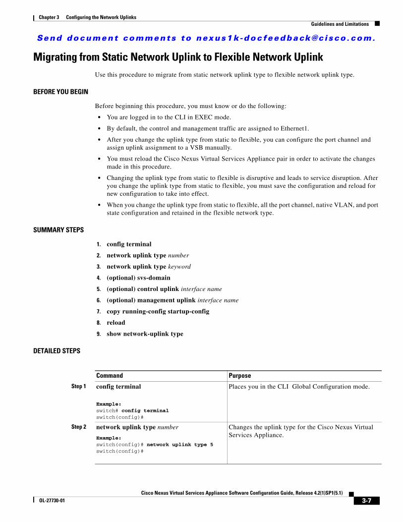
Migrating from Static Network Uplink to Flexible Network UplinkUse this procedure to migrate from static network uplink type to flexible network uplink type.
BEFORE YOU BEGIN
Before beginning this procedure, you must know or do the following:
• You are logged in to the CLI in EXEC mode.
• By default, the control and management traffic are assigned to Ethernet1.
• After you change the uplink type from static to flexible, you can configure the port channel and assign uplink assignment to a VSB manually.
• You must reload the Cisco Nexus Virtual Services Appliance pair in order to activate the changes made in this procedure.
• Changing the uplink type from static to flexible is disruptive and leads to service disruption. After you change the uplink type from static to flexible, you must save the configuration and reload for new configuration to take into effect.
• When you change the uplink type from static to flexible, all the port channel, native VLAN, and port state configuration and retained in the flexible network type.
SUMMARY STEPS
1. config terminal
2. network uplink type number
3. network uplink type keyword
4. (optional) svs-domain
5. (optional) control uplink interface name
6. (optional) management uplink interface name
7. copy running-config startup-config
8. reload
9. show network-uplink type
DETAILED STEPS
Command Purpose
Step 1 config terminal
Example:switch# config terminalswitch(config)#
Places you in the CLI Global Configuration mode.
Step 2 network uplink type number
Example:switch(config)# network uplink type 5switch(config)#
Changes the uplink type for the Cisco Nexus Virtual Services Appliance.
3-7Cisco Nexus Virtual Services Appliance Software Configuration Guide, Release 4.2(1)SP1(5.1)
OL-27730-01
Send document comments to nexus1k -doc feedback@c i sco .com.
Chapter 3 Configuring the Network Uplinks Guidelines and Limitations
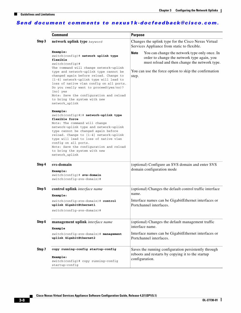
Step 3 network uplink type keyword
Example:switch(config)# network uplink type flexibleswitch(config)# The command will change network-uplink type and network-uplink type cannot be changed again before reload. Change to [1-4] network-uplink type will lead to loss of native vlan config on all ports. Do you really want to proceed(yes/no)? [no] yesNote: Save the configuration and reload to bring the system with new network_uplink
Example:switch(config)#)# network-uplink type flexible force Note: The command will change network-uplink type and network-uplink type cannot be changed again before reload. Change to [1-4] network-uplink type will lead to loss of native vlan config on all ports.Note: Save the configuration and reload to bring the system with new network_uplink
Changes the uplink type for the Cisco Nexus Virtual Services Appliance from static to flexible.
Note You can change the network type only once. In order to change the network type again, you must reload and then change the network type.
You can use the force option to skip the confirmation step.
Step 4 svs-domain
Example:switch(config)# svs-domainswitch(config-svs-domain)#
(optional) Configure an SVS domain and enter SVS domain configuration mode
Step 5 control uplink interface name
Example:
switch(config-svs-domain)# control uplink GigabitEthernet1
switch(config-svs-domain)#
(optional) Changes the default control traffic interface name.
Interface names can be GigabitEthernet interfaces or Portchannel interfaces.
Step 6 management uplink interface name
Example
switch(config-svs-domain)# management uplink GigabitEthernet2
(optional) Changes the default management traffic interface name.
Interface names can be GigabitEthernet interfaces or Portchannel interfaces.
Step 7 copy running-config startup-config
Example:switch(config)# copy running-config startup-config
Saves the running configuration persistently through reboots and restarts by copying it to the startup configuration.
Command Purpose
3-8Cisco Nexus Virtual Services Appliance Software Configuration Guide, Release 4.2(1)SP1(5.1)
OL-27730-01
Send document comments to nexus1k -doc feedback@c i sco .com.
Chapter 3 Configuring the Network UplinksGuidelines and Limitations
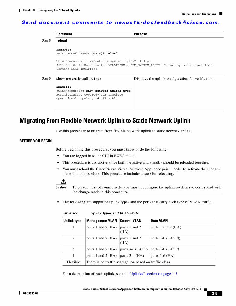
Migrating From Flexible Network Uplink to Static Network UplinkUse this procedure to migrate from flexible network uplink to static network uplink.
BEFORE YOU BEGIN
Before beginning this procedure, you must know or do the following:
• You are logged in to the CLI in EXEC mode.
• This procedure is disruptive since both the active and standby should be reloaded together.
• You must reload the Cisco Nexus Virtual Services Appliance pair in order to activate the changes made in this procedure. This procedure includes a step for reloading.
Caution To prevent loss of connectivity, you must reconfigure the uplink switches to correspond with the change made in this procedure.
• The following are supported uplink types and the ports that carry each type of VLAN traffic.
Table 3-3 Uplink Types and VLAN Ports
Uplink type Management VLAN Control VLAN Data VLAN
1 ports 1 and 2 (HA) ports 1 and 2 (HA)
ports 1 and 2 (HA)
2 ports 1 and 2 (HA) ports 1 and 2 (HA)
ports 3-6 (LACP))
3 ports 1 and 2 (HA) ports 3-6 (LACP) ports 3-6 (LACP)
4 ports 1 and 2 (HA) ports 3-4 (HA) ports 5-6 (HA)
Flexible There is no traffic segregation based on traffic class
For a description of each uplink, see the “Uplinks” section on page 1-5.
Step 8 reload
Example:switch(config-svs-domain)# reload
This command will reboot the system. (y/n)? [n] y2011 Oct 27 10:26:30 switch %PLATFORM-2-PFM_SYSTEM_RESET: Manual system restart from Command Line Interface
Step 9 show network-uplink type
Example:switch(config)# show network uplink typeAdministrative topology id: flexibleOperational topology id: flexible
Displays the uplink configuration for verification.
Command Purpose
3-9Cisco Nexus Virtual Services Appliance Software Configuration Guide, Release 4.2(1)SP1(5.1)
OL-27730-01
Send document comments to nexus1k -doc feedback@c i sco .com.
Chapter 3 Configuring the Network Uplinks Guidelines and Limitations
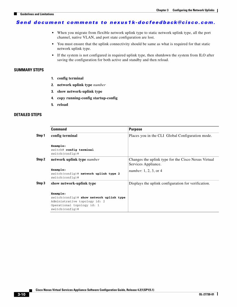
• When you migrate from flexible network uplink type to static network uplink type, all the port channel, native VLAN, and port state configuration are lost.
• You must ensure that the uplink connectivity should be same as what is required for that static network uplink type.
• If the system is not configured in required uplink type, then shutdown the system from ILO after saving the configuration for both active and standby and then reload.
SUMMARY STEPS
1. config terminal
2. network uplink type number
3. show network-uplink type
4. copy running-config startup-config
5. reload
DETAILED STEPS
Command Purpose
Step 1 config terminal
Example:switch# config terminalswitch(config)#
Places you in the CLI Global Configuration mode.
Step 2 network uplink type number
Example:switch(config)# network uplink type 2switch(config)#
Changes the uplink type for the Cisco Nexus Virtual Services Appliance.
number: 1, 2, 3, or 4
Step 3 show network-uplink type
Example:switch(config)# show network uplink typeAdministrative topology id: 2Operational topology id: 1switch(config)#
Displays the uplink configuration for verification.
3-10Cisco Nexus Virtual Services Appliance Software Configuration Guide, Release 4.2(1)SP1(5.1)
OL-27730-01
Send document comments to nexus1k -doc feedback@c i sco .com.
Chapter 3 Configuring the Network UplinksGuidelines and Limitations
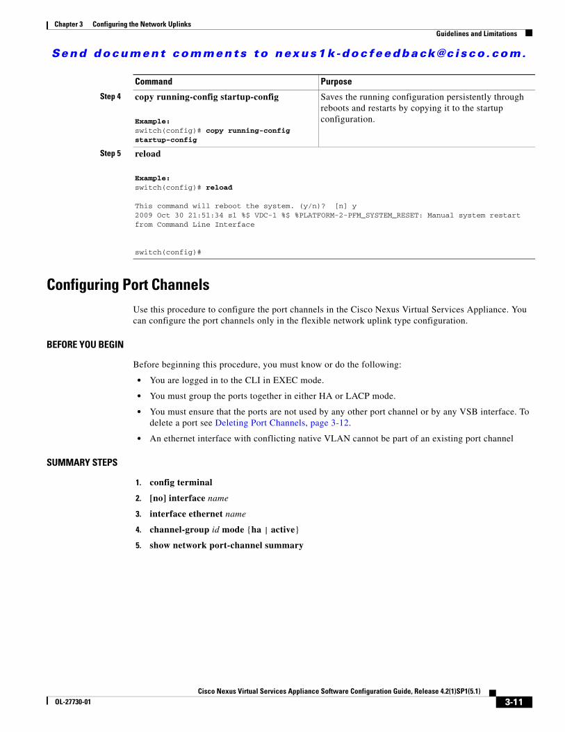
Configuring Port ChannelsUse this procedure to configure the port channels in the Cisco Nexus Virtual Services Appliance. You can configure the port channels only in the flexible network uplink type configuration.
BEFORE YOU BEGIN
Before beginning this procedure, you must know or do the following:
• You are logged in to the CLI in EXEC mode.
• You must group the ports together in either HA or LACP mode.
• You must ensure that the ports are not used by any other port channel or by any VSB interface. To delete a port see Deleting Port Channels, page 3-12.
• An ethernet interface with conflicting native VLAN cannot be part of an existing port channel
SUMMARY STEPS
1. config terminal
2. [no] interface name
3. interface ethernet name
4. channel-group id mode {ha | active}
5. show network port-channel summary
Step 4 copy running-config startup-config
Example:switch(config)# copy running-config startup-config
Saves the running configuration persistently through reboots and restarts by copying it to the startup configuration.
Step 5 reload
Example:switch(config)# reload
This command will reboot the system. (y/n)? [n] y2009 Oct 30 21:51:34 s1 %$ VDC-1 %$ %PLATFORM-2-PFM_SYSTEM_RESET: Manual system restart from Command Line Interface
switch(config)#
Command Purpose
3-11Cisco Nexus Virtual Services Appliance Software Configuration Guide, Release 4.2(1)SP1(5.1)
OL-27730-01
Send document comments to nexus1k -doc feedback@c i sco .com.
Chapter 3 Configuring the Network Uplinks Guidelines and Limitations
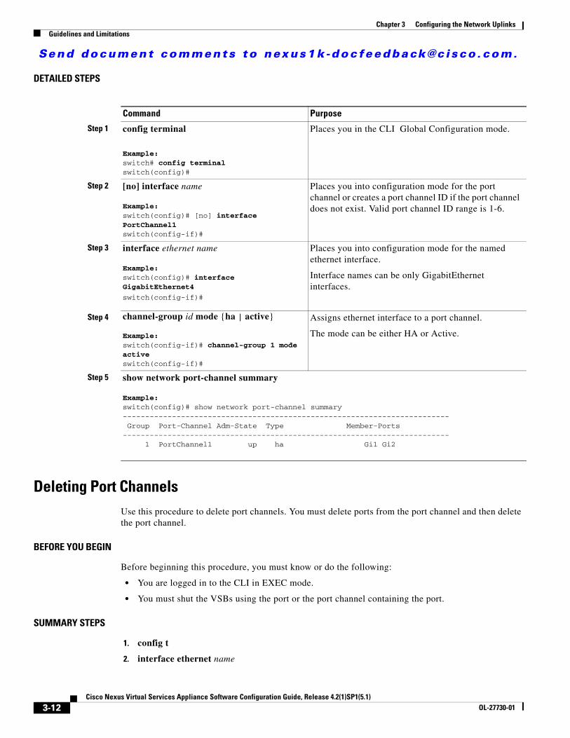
DETAILED STEPS
Command Purpose
Step 1 config terminal
Example:switch# config terminalswitch(config)#
Places you in the CLI Global Configuration mode.
Step 2 [no] interface name
Example:switch(config)# [no] interface PortChannel1switch(config-if)#
Places you into configuration mode for the port channel or creates a port channel ID if the port channel does not exist. Valid port channel ID range is 1-6.
Step 3 interface ethernet name
Example:switch(config)# interface GigabitEthernet4
switch(config-if)#
Places you into configuration mode for the named ethernet interface.
Interface names can be only GigabitEthernet interfaces.
Step 4 channel-group id mode {ha | active}
Example:switch(config-if)# channel-group 1 mode activeswitch(config-if)#
Assigns ethernet interface to a port channel.
The mode can be either HA or Active.
Step 5 show network port-channel summary
Example:switch(config)# show network port-channel summary------------------------------------------------------------------------- Group Port-Channel Adm-State Type Member-Ports------------------------------------------------------------------------- 1 PortChannel1 up ha Gi1 Gi2
Deleting Port ChannelsUse this procedure to delete port channels. You must delete ports from the port channel and then delete the port channel.
BEFORE YOU BEGIN
Before beginning this procedure, you must know or do the following:
• You are logged in to the CLI in EXEC mode.
• You must shut the VSBs using the port or the port channel containing the port.
SUMMARY STEPS
1. config t
2. interface ethernet name
3-12Cisco Nexus Virtual Services Appliance Software Configuration Guide, Release 4.2(1)SP1(5.1)
OL-27730-01
Send document comments to nexus1k -doc feedback@c i sco .com.
Chapter 3 Configuring the Network UplinksGuidelines and Limitations
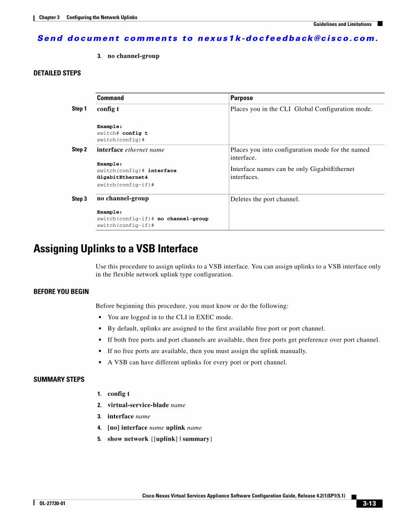
3. no channel-group
DETAILED STEPS
Command Purpose
Step 1 config t
Example:switch# config tswitch(config)#
Places you in the CLI Global Configuration mode.
Step 2 interface ethernet name
Example:switch(config)# interface GigabitEthernet4
switch(config-if)#
Places you into configuration mode for the named interface.
Interface names can be only GigabitEthernet interfaces.
Step 3 no channel-group
Example:switch(config-if)# no channel-group switch(config-if)#
Deletes the port channel.
Assigning Uplinks to a VSB InterfaceUse this procedure to assign uplinks to a VSB interface. You can assign uplinks to a VSB interface only in the flexible network uplink type configuration.
BEFORE YOU BEGIN
Before beginning this procedure, you must know or do the following:
• You are logged in to the CLI in EXEC mode.
• By default, uplinks are assigned to the first available free port or port channel.
• If both free ports and port channels are available, then free ports get preference over port channel.
• If no free ports are available, then you must assign the uplink manually.
• A VSB can have different uplinks for every port or port channel.
SUMMARY STEPS
1. config t
2. virtual-service-blade name
3. interface name
4. [no] interface name uplink name
5. show network {[uplink] | summary}
3-13Cisco Nexus Virtual Services Appliance Software Configuration Guide, Release 4.2(1)SP1(5.1)
OL-27730-01

Send document comments to nexus1k -doc feedback@c i sco .com.
Chapter 3 Configuring the Network Uplinks Guidelines and Limitations
DETAILED STEPS
Command Purpose
Step 1 config t
Example:switch# config tswitch(config)#
Places you in the CLI Global Configuration mode.
Step 2 virtual-service-blade name
Example:switch(config)# virtual-service-blade vsm-5switch(config-vsb-config)#
Places you into configuration mode for the named virtual service blade.
Step 3 interface name
Example: switch(config-vsb-config)# interface control vlan 347
Places you into configuration mode for the named interface.
Step 4 [no] interface name uplink name
Example:switch(config-vsb-config)# interface control uplink PortChannel2
Assigns VSB Ethernet interface to an uplink.
Step 5 show network summary Displays VSB Ethernet interfaces assigned to an uplink.
-Example:
switch(config)#show network summary
----------------------------------------------------------------------------- Port State Uplink-Interface Speed RefCnt MTU Nat-Vlan Oper Admin Oper Admin Oper Admin------------------------------------------------------------------------------ Gi1 up up 1000 0 9000 Gi2 up up 1000 0 9000 Gi3 up up 1000 3 9000 Gi4 down up 1000 0 9000 Gi5 down up 1000 0 9000 Gi6 down up 1000 0 9000 Po1 up up 1000 13 9000 VsbEth6/1 up up Gi3 Gi3 1000 9000 VsbEth6/2 up up Gi3 Gi3 1000 9000 VsbEth6/3 up up Gi3 Gi3 1000 9000 control0 up up Po1 Po1 1000 9000 mgmt0 up up Po1 Po1 1000 9000
3-14Cisco Nexus Virtual Services Appliance Software Configuration Guide, Release 4.2(1)SP1(5.1)
OL-27730-01
Send document comments to nexus1k -doc feedback@c i sco .com.
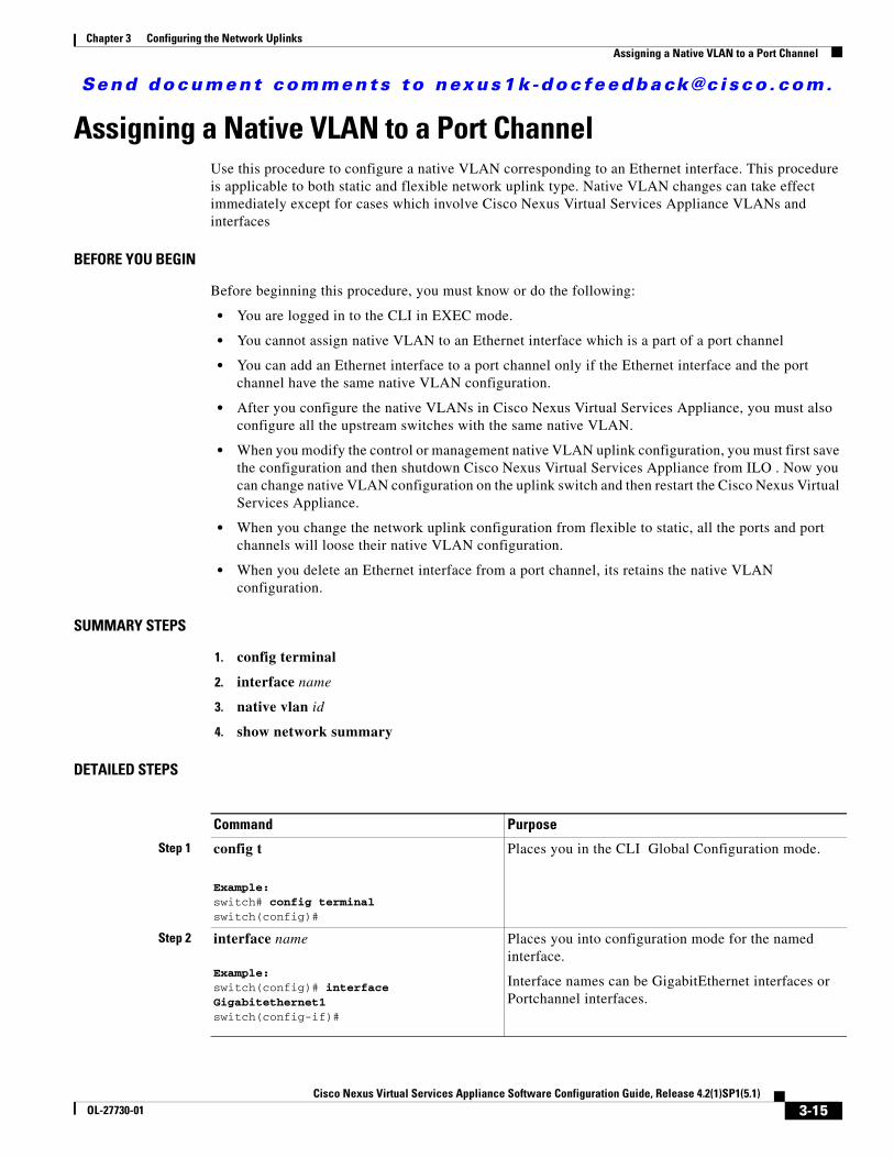
Chapter 3 Configuring the Network UplinksAssigning a Native VLAN to a Port Channel
Assigning a Native VLAN to a Port ChannelUse this procedure to configure a native VLAN corresponding to an Ethernet interface. This procedure is applicable to both static and flexible network uplink type. Native VLAN changes can take effect immediately except for cases which involve Cisco Nexus Virtual Services Appliance VLANs and interfaces
BEFORE YOU BEGIN
Before beginning this procedure, you must know or do the following:
• You are logged in to the CLI in EXEC mode.
• You cannot assign native VLAN to an Ethernet interface which is a part of a port channel
• You can add an Ethernet interface to a port channel only if the Ethernet interface and the port channel have the same native VLAN configuration.
• After you configure the native VLANs in Cisco Nexus Virtual Services Appliance, you must also configure all the upstream switches with the same native VLAN.
• When you modify the control or management native VLAN uplink configuration, you must first save the configuration and then shutdown Cisco Nexus Virtual Services Appliance from ILO . Now you can change native VLAN configuration on the uplink switch and then restart the Cisco Nexus Virtual Services Appliance.
• When you change the network uplink configuration from flexible to static, all the ports and port channels will loose their native VLAN configuration.
• When you delete an Ethernet interface from a port channel, its retains the native VLAN configuration.
SUMMARY STEPS
1. config terminal
2. interface name
3. native vlan id
4. show network summary
DETAILED STEPS
Command Purpose
Step 1 config t
Example:switch# config terminalswitch(config)#
Places you in the CLI Global Configuration mode.
Step 2 interface name
Example:switch(config)# interface Gigabitethernet1switch(config-if)#
Places you into configuration mode for the named interface.
Interface names can be GigabitEthernet interfaces or Portchannel interfaces.
3-15Cisco Nexus Virtual Services Appliance Software Configuration Guide, Release 4.2(1)SP1(5.1)
OL-27730-01

Send document comments to nexus1k -doc feedback@c i sco .com.
Chapter 3 Configuring the Network Uplinks Shutting Down Ports or Port Channel Interfaces
Shutting Down Ports or Port Channel InterfacesUse this procedure to shut down ports or port channels to shut traffic for certain VSBs.
BEFORE YOU BEGIN
Before beginning this procedure, you must know or do the following:
• You are logged in to the CLI in EXEC mode.
SUMMARY STEPS
1. config terminal
2. interface name
3. [no] shutdown [ primary | secondary]
4. show network summary
5. (optional) show network port-channel summary
Step 3 native vlan id
Example:switch(config-if)# native vlan 346switch(config-if)#
Modifies the native VLAN ID.
Step 4 show network summary
Example:switch# show network summary
----------------------------------------------------------------------------- Port State Uplink-Interface Speed RefCnt MTU Nat-Vlan Oper Admin Oper Admin Oper Admin------------------------------------------------------------------------------ Gi1 up up 1000 0 9000 Gi2 up up 1000 0 9000 Gi3 up up 1000 3 9000 Gi4 down up 1000 0 9000 Gi5 down up 1000 0 9000 Gi6 down up 1000 0 9000 Po1 up up 1000 13 9000 VsbEth6/1 up up Gi3 Gi3 1000 9000 VsbEth6/2 up up Gi3 Gi3 1000 9000 VsbEth6/3 up up Gi3 Gi3 1000 9000 control0 up up Po1 Po1 1000 9000 mgmt0 up up Po1 Po1 1000 9000
Command Purpose
3-16Cisco Nexus Virtual Services Appliance Software Configuration Guide, Release 4.2(1)SP1(5.1)
OL-27730-01
Send document comments to nexus1k -doc feedback@c i sco .com.
Chapter 3 Configuring the Network UplinksShutting Down Ports or Port Channel Interfaces
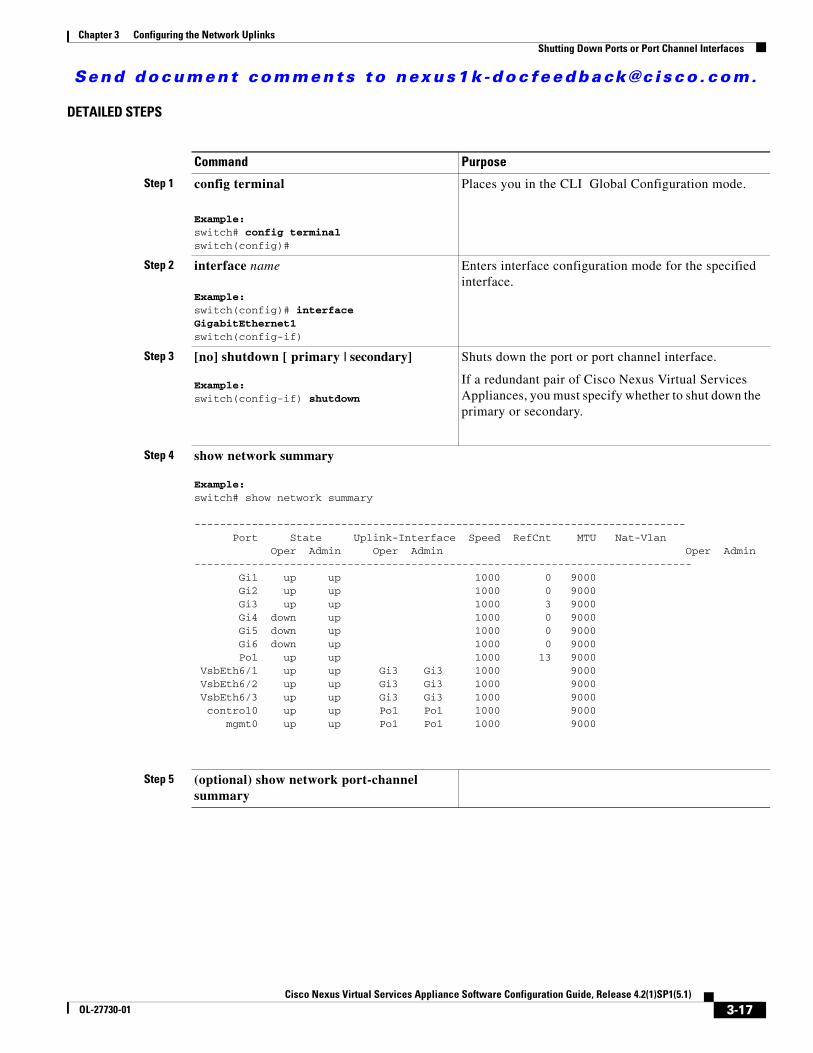
DETAILED STEPS
Command Purpose
Step 1 config terminal
Example:switch# config terminalswitch(config)#
Places you in the CLI Global Configuration mode.
Step 2 interface name
Example:switch(config)# interface GigabitEthernet1switch(config-if)
Enters interface configuration mode for the specified interface.
Step 3 [no] shutdown [ primary | secondary]
Example:switch(config-if) shutdown
Shuts down the port or port channel interface.
If a redundant pair of Cisco Nexus Virtual Services Appliances, you must specify whether to shut down the primary or secondary.
Step 4 show network summary
Example:switch# show network summary
----------------------------------------------------------------------------- Port State Uplink-Interface Speed RefCnt MTU Nat-Vlan Oper Admin Oper Admin Oper Admin------------------------------------------------------------------------------ Gi1 up up 1000 0 9000 Gi2 up up 1000 0 9000 Gi3 up up 1000 3 9000 Gi4 down up 1000 0 9000 Gi5 down up 1000 0 9000 Gi6 down up 1000 0 9000 Po1 up up 1000 13 9000 VsbEth6/1 up up Gi3 Gi3 1000 9000 VsbEth6/2 up up Gi3 Gi3 1000 9000 VsbEth6/3 up up Gi3 Gi3 1000 9000 control0 up up Po1 Po1 1000 9000 mgmt0 up up Po1 Po1 1000 9000
Step 5 (optional) show network port-channel summary
3-17Cisco Nexus Virtual Services Appliance Software Configuration Guide, Release 4.2(1)SP1(5.1)
OL-27730-01
Send document comments to nexus1k -doc feedback@c i sco .com.
Chapter 3 Configuring the Network Uplinks Verifying the Uplink Configuration
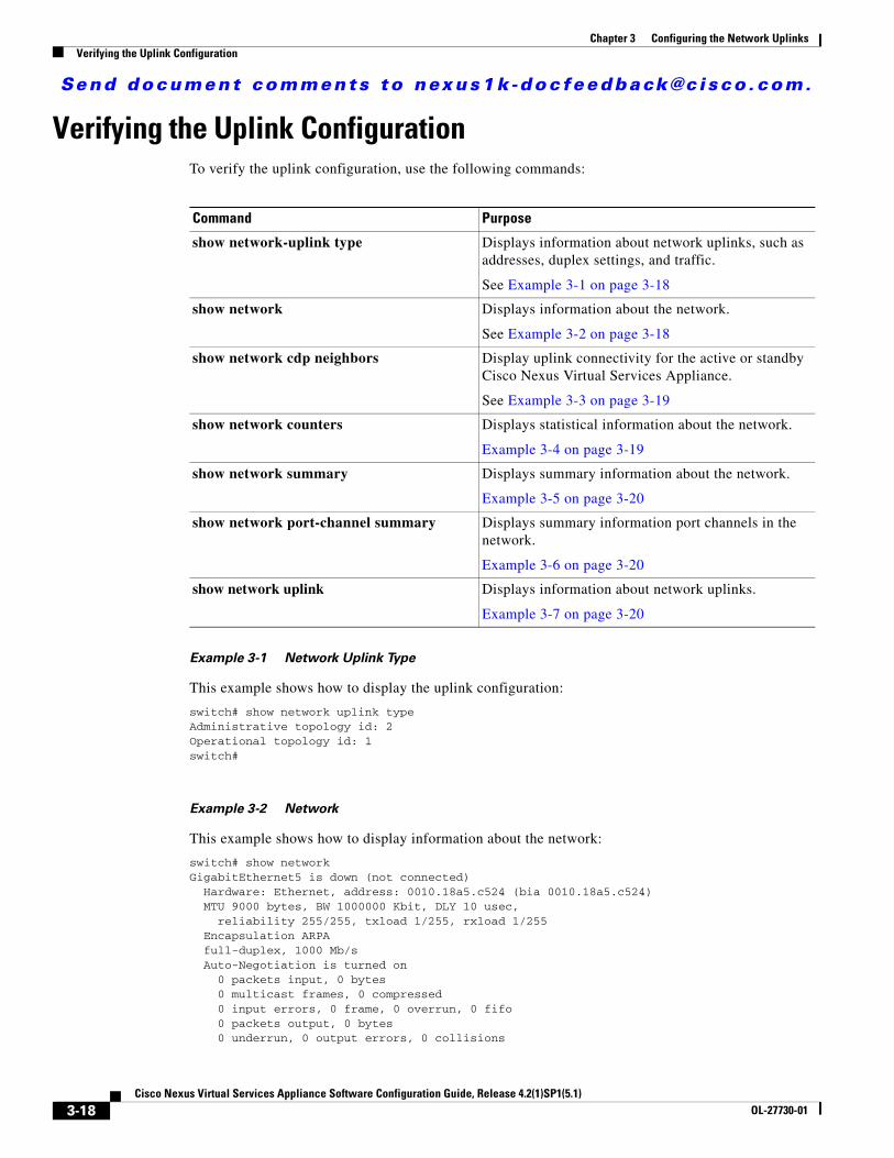
Verifying the Uplink Configuration To verify the uplink configuration, use the following commands:
Command Purpose
show network-uplink type Displays information about network uplinks, such as addresses, duplex settings, and traffic.
See Example 3-1 on page 3-18
show network Displays information about the network.
See Example 3-2 on page 3-18
show network cdp neighbors Display uplink connectivity for the active or standby Cisco Nexus Virtual Services Appliance.
See Example 3-3 on page 3-19
show network counters Displays statistical information about the network.
Example 3-4 on page 3-19
show network summary Displays summary information about the network.
Example 3-5 on page 3-20
show network port-channel summary Displays summary information port channels in the network.
Example 3-6 on page 3-20
show network uplink Displays information about network uplinks.
Example 3-7 on page 3-20
Example 3-1 Network Uplink Type
This example shows how to display the uplink configuration:
switch# show network uplink typeAdministrative topology id: 2Operational topology id: 1switch#
Example 3-2 Network
This example shows how to display information about the network:
switch# show networkGigabitEthernet5 is down (not connected) Hardware: Ethernet, address: 0010.18a5.c524 (bia 0010.18a5.c524) MTU 9000 bytes, BW 1000000 Kbit, DLY 10 usec, reliability 255/255, txload 1/255, rxload 1/255 Encapsulation ARPA full-duplex, 1000 Mb/s Auto-Negotiation is turned on 0 packets input, 0 bytes 0 multicast frames, 0 compressed 0 input errors, 0 frame, 0 overrun, 0 fifo 0 packets output, 0 bytes 0 underrun, 0 output errors, 0 collisions
3-18Cisco Nexus Virtual Services Appliance Software Configuration Guide, Release 4.2(1)SP1(5.1)
OL-27730-01
Send document comments to nexus1k -doc feedback@c i sco .com.
Chapter 3 Configuring the Network UplinksVerifying the Uplink Configuration
0 fifo, 0 carrier errors
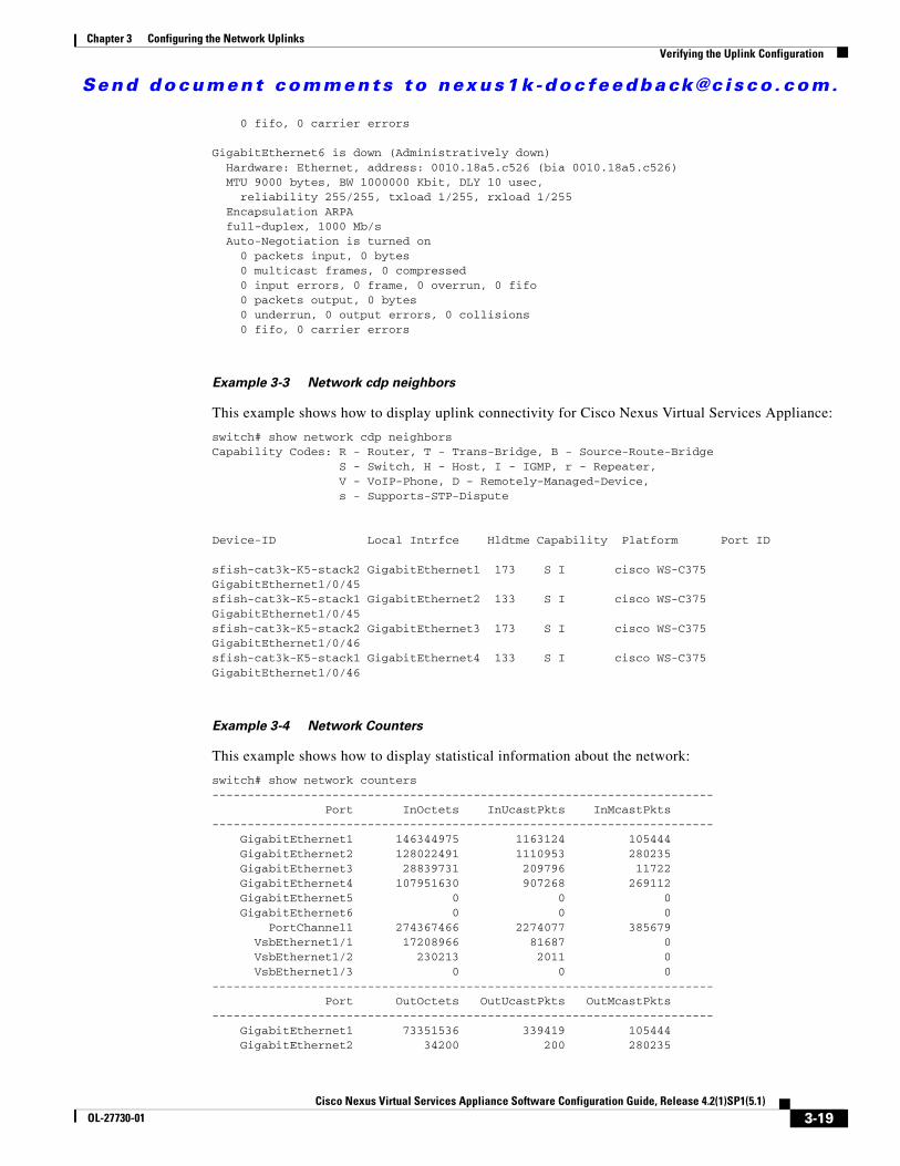
GigabitEthernet6 is down (Administratively down) Hardware: Ethernet, address: 0010.18a5.c526 (bia 0010.18a5.c526) MTU 9000 bytes, BW 1000000 Kbit, DLY 10 usec, reliability 255/255, txload 1/255, rxload 1/255 Encapsulation ARPA full-duplex, 1000 Mb/s Auto-Negotiation is turned on 0 packets input, 0 bytes 0 multicast frames, 0 compressed 0 input errors, 0 frame, 0 overrun, 0 fifo 0 packets output, 0 bytes 0 underrun, 0 output errors, 0 collisions 0 fifo, 0 carrier errors
Example 3-3 Network cdp neighbors
This example shows how to display uplink connectivity for Cisco Nexus Virtual Services Appliance:
switch# show network cdp neighborsCapability Codes: R - Router, T - Trans-Bridge, B - Source-Route-Bridge S - Switch, H - Host, I - IGMP, r - Repeater, V - VoIP-Phone, D - Remotely-Managed-Device, s - Supports-STP-Dispute
Device-ID Local Intrfce Hldtme Capability Platform Port ID
sfish-cat3k-K5-stack2 GigabitEthernet1 173 S I cisco WS-C375 GigabitEthernet1/0/45sfish-cat3k-K5-stack1 GigabitEthernet2 133 S I cisco WS-C375 GigabitEthernet1/0/45sfish-cat3k-K5-stack2 GigabitEthernet3 173 S I cisco WS-C375 GigabitEthernet1/0/46sfish-cat3k-K5-stack1 GigabitEthernet4 133 S I cisco WS-C375 GigabitEthernet1/0/46
Example 3-4 Network Counters
This example shows how to display statistical information about the network:
switch# show network counters----------------------------------------------------------------------- Port InOctets InUcastPkts InMcastPkts----------------------------------------------------------------------- GigabitEthernet1 146344975 1163124 105444 GigabitEthernet2 128022491 1110953 280235 GigabitEthernet3 28839731 209796 11722 GigabitEthernet4 107951630 907268 269112 GigabitEthernet5 0 0 0 GigabitEthernet6 0 0 0 PortChannel1 274367466 2274077 385679 VsbEthernet1/1 17208966 81687 0 VsbEthernet1/2 230213 2011 0 VsbEthernet1/3 0 0 0----------------------------------------------------------------------- Port OutOctets OutUcastPkts OutMcastPkts----------------------------------------------------------------------- GigabitEthernet1 73351536 339419 105444 GigabitEthernet2 34200 200 280235
3-19Cisco Nexus Virtual Services Appliance Software Configuration Guide, Release 4.2(1)SP1(5.1)
OL-27730-01
Send document comments to nexus1k -doc feedback@c i sco .com.
Chapter 3 Configuring the Network Uplinks Verifying the Uplink Configuration
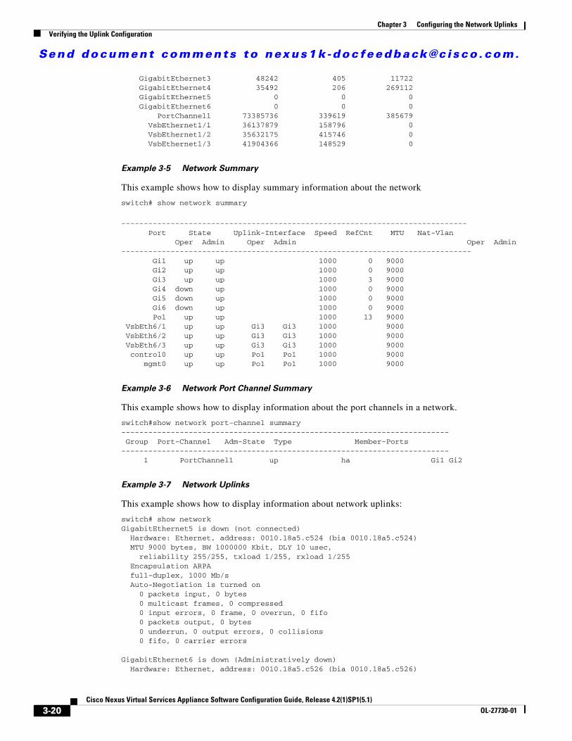
GigabitEthernet3 48242 405 11722 GigabitEthernet4 35492 206 269112 GigabitEthernet5 0 0 0 GigabitEthernet6 0 0 0 PortChannel1 73385736 339619 385679 VsbEthernet1/1 36137879 158796 0 VsbEthernet1/2 35632175 415746 0 VsbEthernet1/3 41904366 148529 0
Example 3-5 Network Summary
This example shows how to display summary information about the network
switch# show network summary
----------------------------------------------------------------------------- Port State Uplink-Interface Speed RefCnt MTU Nat-Vlan Oper Admin Oper Admin Oper Admin------------------------------------------------------------------------------ Gi1 up up 1000 0 9000 Gi2 up up 1000 0 9000 Gi3 up up 1000 3 9000 Gi4 down up 1000 0 9000 Gi5 down up 1000 0 9000 Gi6 down up 1000 0 9000 Po1 up up 1000 13 9000 VsbEth6/1 up up Gi3 Gi3 1000 9000 VsbEth6/2 up up Gi3 Gi3 1000 9000 VsbEth6/3 up up Gi3 Gi3 1000 9000 control0 up up Po1 Po1 1000 9000 mgmt0 up up Po1 Po1 1000 9000
Example 3-6 Network Port Channel Summary
This example shows how to display information about the port channels in a network.
switch#show network port-channel summary------------------------------------------------------------------------- Group Port-Channel Adm-State Type Member-Ports------------------------------------------------------------------------- 1 PortChannel1 up ha Gi1 Gi2
Example 3-7 Network Uplinks
This example shows how to display information about network uplinks:
switch# show networkGigabitEthernet5 is down (not connected) Hardware: Ethernet, address: 0010.18a5.c524 (bia 0010.18a5.c524) MTU 9000 bytes, BW 1000000 Kbit, DLY 10 usec, reliability 255/255, txload 1/255, rxload 1/255 Encapsulation ARPA full-duplex, 1000 Mb/s Auto-Negotiation is turned on 0 packets input, 0 bytes 0 multicast frames, 0 compressed 0 input errors, 0 frame, 0 overrun, 0 fifo 0 packets output, 0 bytes 0 underrun, 0 output errors, 0 collisions 0 fifo, 0 carrier errors
GigabitEthernet6 is down (Administratively down) Hardware: Ethernet, address: 0010.18a5.c526 (bia 0010.18a5.c526)
3-20Cisco Nexus Virtual Services Appliance Software Configuration Guide, Release 4.2(1)SP1(5.1)
OL-27730-01
Send document comments to nexus1k -doc feedback@c i sco .com.
Chapter 3 Configuring the Network UplinksAdditional References
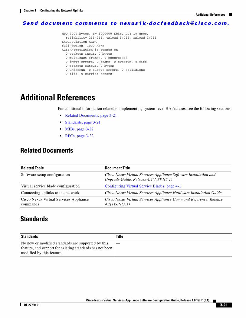
MTU 9000 bytes, BW 1000000 Kbit, DLY 10 usec, reliability 255/255, txload 1/255, rxload 1/255 Encapsulation ARPA full-duplex, 1000 Mb/s Auto-Negotiation is turned on 0 packets input, 0 bytes 0 multicast frames, 0 compressed 0 input errors, 0 frame, 0 overrun, 0 fifo 0 packets output, 0 bytes 0 underrun, 0 output errors, 0 collisions 0 fifo, 0 carrier errors
Additional ReferencesFor additional information related to implementing system-level HA features, see the following sections:
• Related Documents, page 3-21
• Standards, page 3-21
• MIBs, page 3-22
• RFCs, page 3-22
Related Documents
Related Topic Document Title
Software setup configuration Cisco Nexus Virtual Services Appliance Software Installation and Upgrade Guide, Release 4.2(1)SP1(5.1)
Virtual service blade configuration Configuring Virtual Service Blades, page 4-1
Connecting uplinks to the network Cisco Nexus Virtual Services Appliance Hardware Installation Guide
Cisco Nexus Virtual Services Appliance commands
Cisco Nexus Virtual Services Appliance Command Reference, Release 4.2(1)SP1(5.1)
Standards
Standards Title
No new or modified standards are supported by this feature, and support for existing standards has not been modified by this feature.
—
3-21Cisco Nexus Virtual Services Appliance Software Configuration Guide, Release 4.2(1)SP1(5.1)
OL-27730-01
Send document comments to nexus1k -doc feedback@c i sco .com.
Chapter 3 Configuring the Network Uplinks Feature History for Uplink
MIBs
MIBs MIBs Link
No MIBs are supported by this feature —
RFCs
RFCs Title
No RFCs are supported by this feature —
Feature History for UplinkThis section provides the uplink feature release history.
Feature Name Releases Feature Information
Flexible Network Uplink 4.0(4)SP1(4) This feature was introduced.
Uplink 4.0(4)SP1(1) This feature was introduced.
3-22Cisco Nexus Virtual Services Appliance Software Configuration Guide, Release 4.2(1)SP1(5.1)
OL-27730-01