Embed Size (px)
Citation preview

It is of vital importance, before attempting to operate your engine, to read the general 'SAFETY INSTRUCTIONS AND WARNINGS' section on pages 2-6 of this booklet and to strictly adhere to the advice contained therein.
Also, please study the entire contents of this instruction manual, so as to familiarize yourself with the controls and other features of the engine.
Keep these instructions in a safe place so that you may readily refer to them whenever necessary.
It is suggested that any instructions supplied with the aircraft, radio control equipment, etc., are accessible for checking at the same time.
1
2-6
7-8
9
10
20-21
22
27-30
33
15-17
SAFETY INSTRUCTIONS AND WARNINGS ABOUT YOUR O.S. ENGINE
ENGINE CONSTRUCTION,NOTES WHEN APPLYING AN ELECTTRIC STARTER
ABOUT THE ENGINE
BASIC ENGINE PARTS
BEFORE STARTING
INSTALLATION
INSTALLATION OF THE STANDARD ACCESSORIES
FUEL TANK LOCATION
MIXTURE CONTROLS
GLOWPLUG
STARTING
CONTENTS
RUNNING -IN, IDLING ADJUSTMENT CHART
MIXTURE CONTROL VALVE ADJUSTMENT
REALIGNMENT OF MIXTURE CONTROL VALVE,SUBSEQUENT STARTINGPROCEDURE
SUBSEQUENT READJUSTMENT,CARBURETOR CLEANLINESS
TROUBLE SHOOTING WHEN THE ENGINE FAILS TO START
CARE AND MAINTENANCE
ENGINE EXPLODED VIEWS & PARTS LIST
CARBURETOR EXPLODED VIEWS& PARTS LIST
O.S. GENUINE PARTS & ACCESSORIES
THREE VIEW DRAWING
31
32
34-35
36-37
38-39
40-41
11-14
18-19
2342-43
4424-26

2
Remember that your engine is not a "toy", but a highly efficient internal-combustion machine whose power is capable of harming you, or others, if it is misused. As owner, you, alone, are responsible for the safe operation of your engine, so act with discretion and care at all times.If at some future date, your O.S. engine is acquired by another person, we would respectfully request that these instructions are also passed on to its new owner.
SAFETY INSTRUCTIONS AND WARNINGS ABOUT YOUR O.S. ENGINE
The advice which follows is grouped under two headings according to the degree of damage or danger which might arise through misuse or neglect.
WARNINGS NOTES
These cover events which might involve serious (in extreme circumstances, even fatal) injury.
These cover the many other possibilities, generally less obvious sources of danger, but which, under certain circumstances, may also cause damage or injury.
3
WARNINGS
Model engine fuel is poisonous. Do not allow it to come into contact with the eyes or mouth. Always store it in a clearly marked container and out of the reach of children.
Never operate your engine in an en-closed space. Model engines, like auto-mobile engines, exhaust deadly carbon-monoxide. Run your engine only in an open area.
Model engines generate considerable heat. Do not touch any part of your engine until it has cooled. Contact with the muffler (silencer), cylinder head or exhaust header pipe, in particular, may result in a serious burn.
Never touch, or allow any object to come into contact with, the rotating propeller and do not crouch over the engine when it is running.
A weakened or loose propeller may disintegrate or be thrown off and, since propeller tip speeds with powerful engines may exceed 600 feet(180 metres) per second, it will be understood that such a failure could result in serious injury, (see 'NOTES' section relating to propeller safety).
Model engine fuel is also highly flammable. Keep it away from open flame, excessive heat, sources of sparks, or anything else which might ignite it. Do not smoke or allow anyone else to smoke, near to it.

4
NOTESThis engine was designed for model aircraft. Do not attempt to use it for any other purpose.
Mount the engine in your model securely, following the manufacturers' recommenda-tions, using appropriate screws and lock-nuts.
Be sure to use the silencer (muffler) supplied with the engine. Frequent exposure to an open exhaust may eventually impair your hearing. Such noise is also likely to cause annoyance to others over a wide area.
Install a top-quality propeller of the diameter and pitch specified for the engine and aircraft. Locate the propeller on the shaft so that the curved face of the blades faces forward-i.e. in the direction of flight. Firmly tighten the propeller nut, using the correct size wrench.
If you remove the glowplug from the engine and check its condition by connecting the battery leads to it, do not hold the plug with bare fingers.Use an appropriate tool or a folded piece of cloth.
5
NOTESAlways check the tightness of the propeller nut and retighten it, if necessary, before restarting the engine. Also, check the tightness of all the screws and nuts before restarting the engine.
If you install a spinner, make sure that it is a precision made product and that the slots for the propeller blades do not cut into the blade roots and weaken them.
Preferably, use an electric starter. The wearing of safety glasses is also strongly recommended.
Discard any propeller which has become split, cracked, nicked or otherwise rendered unsafe. Never attempt to repair such a propeller: destroy it. Do not modify a propeller in any way, unless you are highly experienced in tuning propellers for specialized competition work such as pylon-racing.
Take care that the glow plug clip or battery leads do not come into contact with the propeller. Also check the linkage to the throttle arm. A disconnected linkage could also foul the propeller.
After starting the engine, carry out any needle-valve readjustments from a safe position behind the rotating propeller. Stop the engine before attempting to make other adjustments to the carburetor.

6
NOTESAdjust the throttle linkage so that the engine stops when the throttle stick and trim lever on the transmitter are fully retarded. Alternatively, the engine may be stopped by cutting off the fuel supply. Never try to stop the engine physically.
Take care that loose clothing (ties, shirt sleeves, scarves, etc.)do not come into contact with the propeller.Do not carry loose objects (such as pencils, screwdrivers, etc.) in a shirt pocket from where they could fall through the propeller arc.
Do not start your engine in an area containing loose gravel or sand. The propeller may throw such material in your face and eyes and cause injury.
For their safety, keep all onlookers (especially small children) well back (at least 20 feet or 6 meters) when preparing your model for flight. If you have to carry the model to the take-off point with the engine running, be especially cautious. Keep the propeller pointed away from you and walk well clear of spectators.
Warning! Immediately after a glowplug-ignition engine has been run and is still warm, conditions sometimes exist whereby it is just possible for the engine to abruptly restart if the propeller is casually flipped over compression WITHOUT the glowplug battery being reconnected. Remember this if you wish to avoid the risk of a painfully rapped knuckle!
7
PistonCylinder Liner
Crankshaft
ENGINE CONSTRUCTIONNear TDC
Slight taper
When the engine is cold. When the engine is hot.
With this engine, the piston will feel tight at the top of its stroke (TDC) when the engine is cold. This is normal. The cylinder bore has a slight taper. The piston and cylinder are designed to achieve a perfect running clearance when they reach operating temperature.

8
NOTES WHEN APPLYINGAN ELECTRIC STARTER
Do not over-prime. This could cause a hydraulic lock and damage the engine on application of the electric starter.
If over-primed, remove glowplug, close needle-valve and apply starter to pump out surplus fuel. Cover the head with a rag to prevent pumped out fuel getting into your eyes.
9
STANDARD ACCESSOIES
Glow Plug No.8 (suppplied with the engine)
Needle Valve Extension Cable Set
E-3020 Silencer AssemblySilencer Retaining Screw (M3x35 2pcs.)
ABOUT THE ENGINE
This is a high performance two stroke engine designed for sport and aerobatic models.
Crankcase and cylinder head are of aero-shape design which give advantage of light weight, compact size.
The new 40J carburetor needlevalve assembly has now been angled backward for safety.
New E-3020 silencer (POWER BOX) develops very effective muffling.Also, the compact body enables it to be fit within most cowls.

10
BASIC ENGINE PARTSCylinder head
Carburetor Type 40J
Crankshaft
Propeller nut
Propeller washer
Drive Hub
Crankcase
Cover Plate
Glowplug
Beam Mount
11
Tools, accessories, etc. The following items are necessary for operating the engine.
BEFORE STARTING
The choice of propeller depends on the design and weight of the aircraft and the type of flying in which you will be engaged.Determine the best size and type after practical experimentation. As a starting point, refer to the props listed in the accompanying table. Slightly larger, or even slightly smaller,
Propellers
12x7-8, 13x6-7Sport
props than those shown in the table may be used, but remember that speed the propeller noise will increase if blade tip is raised, due to higher rpm or if a larger-diameter/lower-pitched prop is used.
Never touch, or allow any object to come into contact with, the rotating propeller and do not crouch over the engine when it is running.
Reminder!
Warning:Make sure that the propeller is well balanced. An unbalanced propeller and/or spinner can cause serious vibration which may weaken parts of the airframe or affect the safety of the radio-controlled system.DO NOT forget the WARNINGS and NOTES on propeller and spinner safety given on front pages.
Since the 55AX is intended to be started with an electric starter, the addition of a spinner assembly for centering the starter sleeve is desirable. Use a heavy-duty, well balanced spinner either of metal or plastic.
Spinner

12
FUEL
The 55AX should be operated on a methanol based fuel containing not less than 18% (volumetric) castor oil, or a top quality synthetic lubricant (or a mixture of both), plus a small percentage (5-20%) of nitromethane for improved flexibility and power. (The carburetor is adjusted a little on the rich side at the factory for a fuel containing 20% lubricant and 15% nitromethane.) Some commercial fuels also contain coloring additives as an aid to fuel level visibility. In some cases, these additives have indicated slightly negative effects on the performance. We would suggest that you use such fuels only if you are satisfied that they do not adversely affect running qualities when compared with familiar standard fuels. When changing to a fuel brand or formula that is different from the one to which you are accustomed, it is a wise precaution to temporarily revert to in-flight running-in procedures, until you are sure that the engine is running entirely satisfactorily.
Model engine fuel is poisonous. Do not allow it to come into contact with the eyes or mouth. Always store it in a clearly marked container and out of the reach of children.
Model engine fuel is also highly flammable. Keep it away from open flame, excessive heat, sources of sparks, or anything else which might ignite it. Do not smoke, or allow anyone else to smoke, near to it.
Reminder!
A fuel tank of approximately 350cc capacity is suggested. This allows around 10-12 minutes flying time, dependent upon the type of fuel used, the size of propeller and on the amount of full-throttle to part-throttle operation throughout the flight.
Fuel Tank
GLOW PLUG
O.S. No.8 glowplug is supplied with the engine.
13
S
GLOWPLUG IGNITER
Commercialy available handy glowplug heater in which the glowplug battery and battery leads are integrated.
Alternatively, one of the purpose-made manual or electric fuel pumps may be used to transfer fuel directly from your fuel container to the fuel tank.
FUEL PUMP
Manual Electric
Electric Starter andStarter Battery
Required when startingthe engine. 12-Volt lead-acid battery
ElectricStarter
Install a filter on the outlet tube of your refueling container to prevent entry of foreign matter into fuel tank. O.S. ‘Super Filters’ (large and small) are available as optional extras.
O.S. Super Filter (Fuel Can Filter)
To prevent the pickup from adhering to the tank wall under suction and restricting fuel flow, slots may be filed I the end of the weight. Alternatively, O.S. Non-Bubble Weight is available as an optional extra.
It is recommended to install a good in-line filter between the fuel tank and carburetor to prevent entry of foreign matter into the carburetor.
O.S. Non-Bubble Weight
Fuel Filter
SILICONE FUEL LINE
Heatproof silicone tubing of approx. 5mm o.d. and 2.5mm i.d. is required for the connection between the fuel tank and engine.

14
8mm
TOOLS
HEX Screwdriver
SCREWDRIVER
Necessary for engine installation.1.5mm, 2.5mm
Necessary for carburetor adjustments.
Phillips Screwdriver
No.2, etc.
Socket Screwdriver
5mm, 5.5mm, 7mm
LONG SOCKET WRENCH WITH PLUG GRIP
Recommended for easy removal and replacement of the angled and recessed glowplug, the O.S.Long Socket Wrench incorporates a special grip.
End Wrenches
10mm, etc.
Needle Nose Pliers
15
It is suggested to use as heavy and rigid as possible engine mounting for highest performance and safe running. Conventional wooden mounting beams should be of rigid hardwood and of at least 15mm or 5/8-in square section. Use at least 3mm steel screws, such as Allen type, with locknuts, for bolting the engine to the bearers..
INSTALLATION
CORRECT
Top surfaces are in the same plane.
INCORRECT
Front view Side view
Re-align the surfacesas necessary
Opposite beamTop surfaces are not in thesame plane.Engine does not rest firmly.
Top surfaces are not in the same plane.
Make sure that the mounting beams are parallel and that theirtop surfaces are in the same plane.

16
How to fasten the mounting screws.
Hardwood mounting beams
Radial motor mount (cast aluminum)
Tighten second nutfirmlydown onto first nut.
Tighten this nut first.
Steel washer
3mm steel nuts
3mm steel screw
Spring washer or lock washer
15mm min.
15mm min. Hardwood such as cherry or maple.
Spring washer3.5mmsteel Allen screw
●�Make sure that these mounting beams are accurately aligned and firmly integrated with the airframe, reinforcing the adjacent structure to absorb vibration. Use 4mm or larger steel screws, preferably Allen type hexagon socket head cap screws, with washers and locknuts, for bolting the engine to the bearers.
O.S. Radial Motor Mount
A special O.S. radial motor mount (Code No.71913100) is available, as an optional extra, for use where firewall type mounting is required.
17
THROTTLE LINKAGE
Before connecting the throttle to its servo, make sure that the throttle arm and linkage safely clear any adjacent part of the airframe structure, etc., as the throttle is opened and closed. Connect the linkage so that the throttle is fully closed when the transmitter throttle stick and its trim lever are at their lowest settings and fully open when the throttle stick is in its fully-open position. Carefully align the appropriate holes in the throttle arm and servo horn so that they move symmetrically and smoothly through their full travel.

18
INSTALLING THE GLOWPLUG
Install washer on glowplug and insert carefully into cylinder-head, making sure that it is not cross-threaded before tightening firmly.
Glow plug
Washer
NEEDLE-VALVE EXTENSIONThe needle-valve supplied with this engine is designed to incorporate an extension so that, when the engine is enclosed within the fuselage, the needle-valve may be adjusted from the outside. For this purpose, Needle Valve Extension Cable Set is supplied with the engine. If a longer extension is reguired, cut a commercially available rod to the required length, bend one end to an L shape, insert it into needle's center hole and secure it by tightening the set-screw in the needle-valve knob with 1.5mm Allen key.
Needle Valve Extension Cable Set
1.5mm Allen key. Set Screw
INSTALLATION OF THESTANDARD ACCESSORIES
19
The exhaust outlet of the silencer can be rotated to any desired position in the following manner:
Loosen the locknut and assembly screw.
Set the exhaust outlet at the required posi-tion by rotating the rear part of the silencer.
Re-tighten the assembly screw, followed by the locknut.
INSTALLING SILENCERSecure the silencer to the engine by means of two retaining screws supplied after the engine is securely mounted to a test bench or a model.
It is recommended to seal the fitting faces of engine exhaust and silencer with silicone sealant.
Assembly screw
Cone baffle
Turn to requlredposition
Exhaustoutlet
Locknut
Exhaust pressure nipple
E-3020 Silencer
Model engines generate considerable heat. Do not touch any part of your engine until it has cooled. Contact with the muffler (silencer), cylinder head or exhaust header pipe, in particular, may result in a serious burn. Keep your hands and face away from exhaust gas or you will suffer a burn.
Reminder!
1)
2)
3)

20
Suggested fuel tank capacity is approx 350cc. This will allow 10-12 minute flights.
Be sure to use a pressurized fuel system by connecting the muffler pressure nipple to the vent-pipe of the fuel tank.
FUEL TANK LOCATION
Make sure that the tank is well rinsed out with methanol or glow fuel before installation and that the pickup weight is well clear of the bottom of the tank when held vertically.
Use a suitable length of best quality 5mm OD x 2.5mm ID silicone tubing for fuel tubing.
Fuel plumb end should be 15mm away from the tank bottom.
Locate the fuel tank so that the center of the carburetor is flush with the center of the fuel tank.
21
Attention to tank height
Install the fuel tank so that the center of the carburetor is flush with the center of the fuel tank.
Approx. 15mm
Plug (commercially available)
For carburetor

22
MIXTURE CONTROLS
The Needle ValveWhen set to produce maximum power at full throttle, this establishes the basic fuel/air mixture strength. The correct mixture is then maintained by the carburetor's built-in automatic mixture control system to cover the engine's requirements at reduced throttle settings.
The Mixture Control ValveThis meters fuel flow at part-throttle and idling speeds to ensure reliable operation as the throttle is opened and closed. The Mixture Control Valve is factory set for the approximate best result. First run the engine as received and readjust the Mixture Control Screw only if necessary.
Two mixture controls are provided on this Carburetor.
Needle Valve
Mixture Control Valve
Mixture Control Valve of the carburetor is set at basic position ( a little on the rich side) at the factory. However, minor readjustment will be required for a fuel used, atmospheric conditions and a model. When a good result is not obtained with the factory setting, readjust it according to the MIXTURE CONTROL VALVE ADJUSTMENT section. Please note during a running-in period flights should be made with a slightly rich needle setting. Therefore, during a running-in period proper carburetor responses will not be obtained. Adjust it at optimum position after the running-in is completed.
23
GLOWPLUG
The role of the glowplug
Glowplug life
Particularly in the case of very high performance engines, glowplugs must be regarded as expendable items. However, plug life can be extended and engine performance maintained by careful use, i.e.:
Install a plug suitable for the engine.
Use fuel containing a moderate percentage of nitromethane unless more is essential for racing events.
Do not run the engine too lean and do not leave the battery connected while adjusting the needle.
With a glowplug engine, ignition is initiated by the application of a 1.5-volt power source. When the battery is disconnected, the heat retained within the combustion chamber remains sufficient to keep the plug filament glowing, thereby continuing to keep the engine running. Ignition timing is 'automatic' : under reduced load, allowing higher rpm, the plug becomes hotter and, appropriately, fires the fuel/air charge earlier; conversely, at reduced rpm, the plug become cooler and ignition is retarded.
Apart from when actually burned out, a plug may need to be replaced because it no longer delivers its best performance, such as when:
When to replace the glowplug
Filament surface has roughened and turned white. Filament coil has become distorted.Foreign matter has adhered to filament or plug body has corroded.Engine tends to cut out when idling.Starting qualities deteriorate.
Since the glowplug and fuel combination used may have a marked effect on per-formance and reliability, it would be
worthwhile to experiment with different plug types. An O.S. No.8 glowplug is supplied with the engine. Rec-ommended O.S. plugs are the No.8 and A5. Carefully install plug finger-tight, before final tightening with the correct size plug wrench.

24
!��
STARTING
Be sure to use an electric starter to start the engine.
Fill the fuel tank with fuel. When filled, prevent fuel flowing into the carburetor with a commercially available fuel stopper, etc. Release the stopper before starting the engine.
1.
2.
Starting procedure is as follows:
WARNINGWhen checking the plug element hold the plug with tools, such as pliers, etc.Do not hold near your face or the fuel remaining in the filament may burn you.
Glow Plug Igniter
PliersElement glows when energized.
Replace the plug when the element does not glow or is burnt out.
Make sure that plug element glows red, and install the plug in the cylinder head.
Never fail to check the tightness of screws and nuts, especially engine mounting and moving parts (e.g. throttle lever).
25
Connect battery leads to glowplug.
Check that the needle-valve is closed. (Do not overtighten.) Now open the needle-valve counter-clockwise 2-2.5 turns to the starting setting.
3.
4. Open the throttle approx. one-quarter.
(This is to avoid unnecessarily high r.p.m. when the engine starts.)
Turn needle-valve clockwise to close (for leaner mixture)
Turn needle-valve counter-clockwise to open (for richer mixture)
Mark
Close
Open
Fully closed position
Fully opened position
Set at this point
14
34
5. Apply the starter and press the starter switch for 5-6 seconds to prime the engine.
6.
Bring electric starter into contact with spin-ner-nut or spinner and depress starter switch for one or two seconds. Repeat if necessary.When the engine starts, withdraw the starter immediately.
7.

26
Attention :Do not choke the carburetor air intake when applying the starter. This could cause an excessive amount of fuel to be drawn into the cylinder which may initiate an hydraulic lock and damage the engine.If the engine does not start within 10 repeat applications of the starter, remove the glow-plug, check that it glows brightly and that the cylinder is not flooded with fuel. (To eject excess fuel, close needle-valve and apply starter with glowplug removed.) Then try again.
Note:Make sure that the throttle linkage is made so that the throttle is fully closed when the throttle lever as well as trim lever on the transmitter are fully pulled down.
How to stop the enginePull down the throttle lever and trim lever on the transmitter fully.
CloseVERY IMPORTANT!Before being operated at full power (i.e. at full-throttle and with the needle-valve closed to its optimum setting) the engine must be adequately run-in, otherwise there is a danger of it becoming overheated and damaged.
27
Install the engine with the propeller intended for your model. Open the needle-valve to the advised starting setting and start the engine. If the engine stops when the glow plug battery is disconnected, open the needle-valve to the point where the engine does not stop.Run the engine for one minute with the throttle fully open, but with the needle-valve adjusted for rich, slow "four-cycle"operation.
RUNNING-IN (“Breaking-in”)
Now close the needle-valve until the engine speeds up to "two-cycle"operation and allow it to run for about 10 seconds, then reopen the needle-valve to bring the engine back to "four-cycle"operation and run it for another 10 seconds. Repeat this procedure until the fuel tank is empty.
2.
All internal-combustion engines benefit from extra care when they are run for the first few timesknown as running-in or breaking-in. This allows the working parts to mate together under load at operating temperature. Therefore, it is vitally important to complete the break-in before allowing the engine to run continuously at high speed and before finalizing carburetor adjustments. However, because O.S. engines are produced with the aid of the finest modern precision machinery and from the best and most suitable materials, only a short and simple running-in procedure is called for and can be carried out with the engine installed in the model. The process is as follows.
1.
Re-start and adjust the needle-valve so that the engine just breaks into "two-cycle" from "four-cycle" operation, then make three or four flights, avoiding successive "nose-up" flights.
3.

28
During subsequent flights, the needle-valve can be gradually closed to give more power. However, if the engine shows signs of running too lean, the next flight should be set rich. After a total of ten flights, the engine should run continuously, on its optimum needle-valve setting, without loss of power as it warms up.
After the completion of the running-in adjust the carburetor at optimum setting referring to MIXTURE CONTROL VALVE ADJUSTMENT section and SUBSEQUENT READJUSTMENT section.
4.
5.
As the needle-valve is closed slowly and grad-ually, the engine r.p.m. will increase and a continuous high-pitched exhaust note, only, will be heard. Close the needle-valve 10-15 degrees and wait for the change of r.p.m. After the engine r.p.m. increases turn the nee-dle-valve another 10-15 degrees and wait for the next change of r.p.m. As the speed of the engine does not instantly change with needle-valve readjustment, small movements, with pauses between, are necessary to arrive at the optimum setting.
Optimum needle setting(1)
Optimum needle setting(2)
Slowly advance the throttle to its fully open position, then gradually close the needle-valve until the exhaust note begins to change. (4-cycle to 2-cycle)
29
20-45degrees
Needle-valve adjustment diagram
This diagram is for reference purposes only. Actual needle positions may differ from those shown.
Note :
Practical best(optimum) needle-valve setting
Exhaust note starts to change.
Disconnect battery leads from glowplug at about this point.
Clear, high-pitched two-stroke exhaust note
Maximum rpm setting("Lean").
STARTING"Rich" needle-valve setting when starting the engine.
The engine may stop if the battery leads are disconnected from the glowplug while the engine is running rich.
Enginestops
Revo
lutio
ns
sta
rtt
todecre
ase
.to
de
Intermittent, high-pitched two-stroke note superimposedon low "four-stroke" sound.
Note: Although this is a two-stroke engine it fires like a four-stroke at these rich needle-valve settings-i.e. ignition of the fuel charge takes place at every fourth stroke of the piston instead of at every second stroke.
1
2
3
4
5
67
30
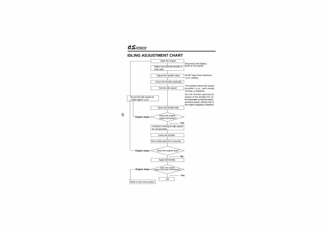
IDLING ADJUSTMENT CHARTStart the engine.
Make sure that the throttle isfully open.
Adjust the needle-valve.
Close the throttle gradually.
Set the idle speed
Open the throttle fully.
Does the engineregain full power?
Continue running at high speedfor 10 seconds.
Close the throttle.
Run at idle speed for 5 seconds.
Does the engine stop?
Apply full throttle.
Does the engineregain full power immediately?
OKRefer to the next section.
Re-set the idle speed ata little higher r.p.m.
Set the throttle opening by means of the throttle trim onthe transmitter so that the lowestpractical speed, without risk ofthe engine stopping,is obtained.
The position where the lowestpossible r.p.m. ,with steady running, is obtained.
20-45 open from maximumr.p.m. setting.
Yes.
No.
Yes.
Engine stops.
Engine stops.
Disconnect the batteryleads at mid speed.
Engine stops.

31
MIXTURE CONTROL VALVE ADJUSTMENTWith the engine running, close the throttle and allow it to idle for about five seconds, then open the throttle fully. If, at this point, the engine is slow to pick up and produces an excess of exhaust smoke, the mixture is too rich. Correct this condition by turning the Mixture Control Screw clockwise 15-30 degrees. If the mixture is excessively rich, engine rpm will become unstable: opening the throttle will produce a great deal of smoke and rpm may drop suddenly or the engine may stop. This condition may also be initiated by excessively prolonged idling. If,on the other hand, the mixture is too lean, this will be indicated by a marked lack of exhaust smoke and a tendency for the engine to cut out when the throttle is opened.
Note: Mixture Control Valve adjustments should be made in steps of 15-30˚ initially, carefully checking the effect, on throttle response, of each small adjustment.
In this case, turn the Mixture Control Screw counter-clockwise 90 degrees to positively enrich the idle mixture, then turn the screw clockwise gradually until the engine regains full power cleanly when the throttle is reopened. Carry out adjustments patiently until the engine responds quickly and positively to the throttle control.
32
REALIGNMENT OF MIXTURE CONTROL VALVE
In the course of making carburetor adjustments, it is just possible that the Mixture Control Valve may be inadvertently screwed in or out too far and thereby moved beyond its effective adjustment range. Its basic setting can be re-established as follows: Close the throttle rotor gradually from the fully opened position until it is just fully closed. (Do not turn further.) Then, screw in the Mixture Control Screw until it stops. Now unscrew the Mixture Control Screw approx. 1.5turn. This is the basic position.
SUBSEQUENT STARTING PROCEDURE
Once the optimum needle-valve setting has been established (see page 29, Needle-valve adjustment diagram) the procedure for starting may be simplified as follows.
Open the needle-valve one half-turn (180 degrees) from the optimum setting.
Set the throttle one-quarter open from the fully closed position, energize the glowplug and apply the electric starter. When the engine starts, re-open the throttle and re-adjust the needle-valve to the optimum setting.
When re-starting the engine on the same day, provided that atmospheric conditions have not changed significantly, it may be practicable to re-start the engine on its optimum(running) setting.
Note:
1.
2.
33
SUBSEQUENT READJUSTMENTOnce the engine has been run-in and the controls properly set up, it should be unnecessary to alter the mixture settings; except to make minor adjustments to the Needle-Valve occasionally, to take account of variations in climatic conditions. The use of a different fuel, however, particularly one containing more, or less, nitromethane and/or a different type or proportion of lubricating oil, is likely to call for some readjustment of the Needle-Valve. Remember that, as a safety measure, it is advisable to increase the Needle-Valve opening by an extra half-turn counter-clockwise, prior to establishing a new setting. The same applies if the silencer type is changed. A different silencer may alter the exhaust pressure applied to the fuel feed and call for a revised Needle-Valve setting. The use of a different glowplug may also require compensating carburetor readjustments.
CARBURETOR CLEANLINESS
The correct functioning of the carburetor depends on its small fuel orifices remaining clear. The minute particles of foreign matter that are present in any fuel, can easily partially obstruct these orifices and upset mixture strength so that engine performance becomes erratic and unreliable.O.S.'Super-Filters'(large and small) are available, as optional extras, to deal with this problem. One of these filters, installed on the outlet tube inside your refueling container, will prevent the entry of foreign material into the fuel tank. It is also recommended that a good in-line filter be installed between the tank and needle-valve. Do not forget to clean the filters regularly to remove dirt and lint that accumulate on the filter screen. Also, clean the carburetor itself occasionally.
34
1
2
3
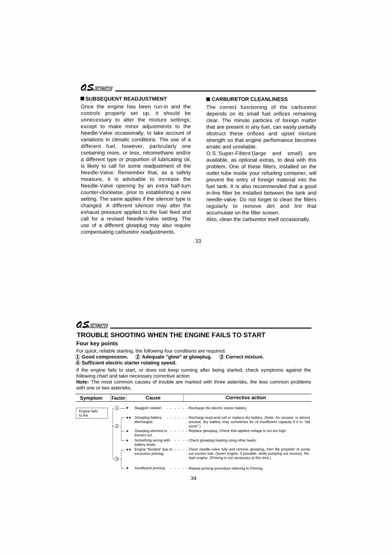
Symptom Factor Cause Corrective action
Recharge the electric starter battery.
Recharge lead-acid cell or replace dry battery. (Note: An unused, or almost unused, dry battery may sometimes be of insufficient capacity if it is "old stock".)Replace glowplug. Check that applied voltage is not too high.
Check glowplug heating using other leads.
Close needle-valve fully and remove glowplug, then flip propeller to pump out excess fuel. (Invert engine, if possible, while pumping out excess). Re-start engine. (Priming is not necessary at this time.)
Repeat priming procedure referring to Priming.
Sluggish rotation
Glowplug battery discharged.
Glowplug element is burned outSomething wrong with battery leads.Engine "flooded" due to excessive priming.
Insufficient priming.
Engine failsto fire.
. . . . . .
. . . . . .
. . . . .
. . . .
. . . .
. . . . .
TROUBLE SHOOTING WHEN THE ENGINE FAILS TO STARTFour key pointsFor quick, reliable starting, the following four conditions are required.1 Good compression. 2 Adequate "glow" at glowplug. 3 Correct mixture. 4 Sufficient electric starter rotating speed.If the engine fails to start, or does not keep running after being started, check symptoms against the following chart and take necessary corrective action.Note: The most common causes of trouble are marked with three asterisks, the less common problems with one or two asterisks.

35
. . . . .
. . . . . . . .
. . . . . .
. . . . . .
. . . . .
. . . . . . .
. . . . .
. . . . . . .
. . .
Symptom Factor Cause Corrective action
2
3
1
2
3
3
3
3
2
Voltage too high or too low. Re-check and readjust referring to "BEFORE STARTING" .
Continue applying an electric starter. If the engine dos not start after more than 4 tries, disconnect the current to the glowplug and leave for a few minutes., then re-energize plug and apply starter. If the engine still does not start, remove glowplug and pump out excess fuel by applying the starter.
Then re-start. (Priming is not necessary.)Recharge the electric starter battery.
Recharge lead-acid cell or replace dry battery.(Note: An unused, or almost unused, dry battery may sometimes be of insufficient capacity if it is "old stock".)
Repeat priming procedure referring to Priming.
Close needle-valve half turn (180 ) and wait for several minutes then re-start.(Priming is not necessary.)
Make sure that tank is filled with fuel. Check that there is not something wrong with the fuel line (kinked or split). Check that carburettor is not clogged with dirt.
Close the needle-valve a little before disconnecting current to the glowplug.
Change fuel or glowplug.
Incorrect heating of glowplug.Over priming.
Sluggish rotation.
Glowplug batterydischarged.
Insufficient priming.
Mixture too rich.
Fuel not reaching the engine.
Mixture too rich.
Mismatch of glow plug and fuel.
Engine firesintermittently butdoes not run.
Engine fires onceor twice, thenfails to fire.
Engine starts butrpm decreasesand engine eventuallystops.
Engine starts,rpm increasesand engine cuts out.
Engine stops whenthe current to theglowplug is discon-nected after starting.
36
CARE AND MAINTENANCEPlease pay attention to the matters described below to ensure that your engine serves you well in regard to performance, reliability and long life.
As previously mentioned, it is vitally important to avoid operating the engine in conditions where dust, disturbed by the propeller, may be deposited on the engine and enter its working parts.
Remember to keep your fuel container closed to prevent foreign matter from contaminating the fuel.
Install a fuel filter to prevent dirt and dust in the fuel container from entering the fuel tank. O.S. Super Filters (L) and (S) are available as optional extras.
Install an in-line fuel filter between the tank and carburetor to prevent dirt and dust in the tank from entering the carburetor.
If these precautions are neglected, restriction of fuel flow may cause the engine to cut out, or the fuel/air mixture to become too lean causing the engine to overheat.
Clean these filters periodically.
The use of modern high-performance alcohol based model engine fuels, while promoting cooler running, improved anti-detonation combustion and increased power, have the disadvantage of causing corrosion due to the acid by-products of combustion. The use of nitromethane in the fuel can also contribute to the problem.
37
Do not close the needlevalve and mixture control valve too far as this will cause a lean setting and over heating of the engine. This can, in turn, create nitromethane oxide leading to internal rusting of the engine. Always adjust the needlevalve slightly on the rich side of peak rpm.
Do not leave unused fuel in the engine at the conclusion of a day’s flying. Accepted practice is to cut off the fuel supply while the engine is still running at full throttle, then expel as much fuel residue as possible by turning the engine over 5-10 seconds with the electric starter. Finally, inject some after-run oil through the glowplug hole and turn the engine over several times by hand.
When the engine is not to be used for some months (for example, as between flying seasons), a worthwhile precaution is to remove it from the airframe and, after washing off the exterior with alcohol (not gasoline nor kerosene), remove carefully the carburetor with intake pipe, glow plug and all silicone tubing and put them safely aside. Then, immerse the engine in a container of alcohol. Rotate the crankshaft while the engine is immersed. If foreign matter is visible in the alcohol, rinse the engine again in clean alcohol. Finally, shake off and dry the alcohol ,and inject some after-run oil in the glowplug hole and rotate the crankshaft several times by hand. Reinstall the carburetor with intake pipe and glowplug on the engine and keep it in a dry place after putting in a vinyl bag.

38
ENGINE EXPLODED VIEW
Type of screw
C...Cap Screw M...Oval Fillister-Head ScrewF...Flat Head Screw N...Round Head Screw S...Set Screw
C.M3x15
C.M3x8
1
2
34
5
6
7 89
11
12
13
1410
15
16
17
39
ENGINEN PARTS LIST
The specifications are subject to alteration for improvement without notice.
1234567891011121314151617
2570400025703000252060002521700025205000257810002321000723209003246080004612000026731002257010002673001025702000257140002570700024613000716080017220008024625100256253002268195725425400
DescriptionCode No.No.Cylinder HeadCylinder & Piston AssemblyPiston PinPiston Pin Retainer (2pcs.)Connecting RodCarburetor Complete (Type 40J)Propeller NutPropeller WasherDrive HubThrust WasherCrankshaft Ball Bearing (F)CrankcaseCrankshaft Ball Bearing (R)CrankshaftGasket SetCover PlateScrew SetGlow Plug No.8Needle Valve Extension Cable SetE-3020 Silencer Assembly Assembly Screw Pressure Nipple (No.7) Silencer Retaining Screw (C.M3x35 2pcs.)

40
12 4 5
7
S.M3X3
3
6
3-1 3-2
7-1
7-2
8
9
N.+M3.5x6
N.+M3x6
7-3
7-4
7-5
CARBURETOR EXPLODED VIEW
Type of screw
C...Cap Screw M...Oval Fillister-Head ScrewF...Flat Head Screw N...Round Head Screw S...Set Screw
41
123
3-13-24567
7-17-27-37-47-589
27881400257812002578160046066319227818002578110045581820226819534428190044281970249818372638150127381940267113052901501925081700
CARBURETOR PARTS LIST
DescriptionCode No.No.
Specifications are subject to alteration for improvement without notice.
Throttle Lever AssemblyCarburetor RotorMixture Control Valve Assembly "O" Ring (L) (2pcs.) "O" Ring (S) (2pcs.)Carburetor BodyRoter Guide ScrewFuel Inlet (No.1)Needle-valve Assembly Needle Assembly "O" Ring (2pcs.) Set Screw Needle-valve Holder Assembly Ratchet SpringCarburetor Rubber GasketCarburetor Retaining Screw

42
(71913100)
(73101000)
(73101020)
(71531000)(25425600) (71531010)
No.8(71608001)
A5(71605100)
1/4"-M5
O.S.GLOW PLUG
O.S. GENUINE PARTS & ACCESSORIESPROPELLER NUT SETSFOR 2C SPINNER
RADIAL MOTOR MOUNT
NON-BUBBLEWEIGHT
SILENCER EXTENSIONADAPTORS
(23024009)
1/4"-28(L)
SPINNER NUT
1/4"-28
LONG PROPELLERNUT SETS
NON-BUBBLEWEIGHT
S
43
(71521000)
(72403050)
M3x8(79871110)
M3x15(79871150)
(79870030)M3 M3 (55500002)
The specifications are subject to alteration for improvement without notice.
SUPER FILTER
LONG SOCKET WRENCH WITH PLUG GRIP
LOCK WASHER (10sets)BLIND NUT
CAP SCREW SETS(10pcs./sets)
(L)
(79870040)M4 M4 (55500003)

44
E-3020E-3020
100.5
92
UNF1/4-28
38.1
43.2
4
112.627.2 60.4 25
36.7
17.5
18.5
72.6
44
3651
31.7
2128
.5
37.1
2222
42.5
36
3
87.7
22.6
8.93 cc / 0.545 cu.in.23.0 mm / 0.906 in.21.5 mm / 0.846 in.2.000-17.000 r.p.m.1.75 ps / 16.000r.p.m.404 g / 14.25 oz.
120 g / 4.23 oz.
Displacement Bore Stroke Practical R.P.M. Power output Weight
SPECIFICATIONS
Dimensions(mm)
THREE VIEW DRAWING
E-3010 Silencer Assembly
C Copyright 2006 by O.S.Engines Mfg. Co., Ltd. All rights reserved. Printed in Japan. 60091850 090600
TEL. (06) 6702-0225FAX. (06) 6704-2722
6-15 3-Chome Imagawa Higashisumiyoshi-ku Osaka 546-0003, Japan
URL : http://www.os-engines.co.jp