Embed Size (px)
Citation preview

FLZA3330 RTF FLZA3332 Tx-R
READ THROUGH THIS MANUAL BEFORE STARTING CONSTRUCTION. IT CONTAINS IMPORTANTINSTRUCTIONS AND WARNINGS CONCERNING THE ASSEMBLY AND USE OF THIS MODEL.
WARRANTYHobbico guarantees this kit to be free from defects in both material and workmanship at the date of purchase. This warranty does not cover any component parts damaged by use or modification. In no case shall Hobbico’s liability exceed the original cost of the purchased kit. Further, Hobbico reserves the right to change or modify this warranty without notice.
In that Hobbico has no control over the final assembly or material used for final assembly, no liability shall be assumed nor accepted for any damage resulting from the use by the user of the final user-assembled product. By the act of using the user-assembled product, the user accepts all resulting liability.
If the buyer is not prepared to accept the liability associated with the use of this product, the buyer is advised to return
this kit immediately in new and unused condition to the place of purchase.
To make a warranty claim send the defective part or item to Hobby Services at the address below:
Hobby Services3002 N. Apollo Dr. Suite 1Champaign IL 61822 USA
Include a letter stating your name, return shipping address, as much contact information as possible (daytime telephone number, fax number, e-mail address), a detailed description of the problem and a photocopy of the purchase receipt. Upon receipt of the package the problem will be evaluated as quickly as possible.
I N S T R U C T I O N M A N U A L
Entire Contents © 2012 Hobbico,® Inc. All rights reserved.
Champaign, Illinois (217) 398-8970E-mail: [email protected]
SPECIFICATIONSWingspan: 73 in [1855 mm]
Wing Area: 526 in2 [33.9 dm2]
Wing Loading: 7.9−8.5 oz/ft2 [24−26 g/dm2]
Length: 47 in [1195 mm]
Weight: 29− 31 oz [820−880 g]
Radio: 4 – 5-channel
Motor: 28-30-1300 kV outrunner
™
™
2
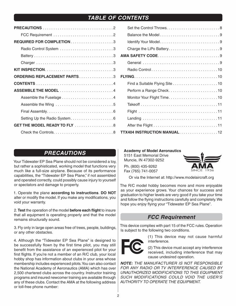
PRECAUTIONSYour Tidewater EP Sea Plane should not be considered a toy, but rather a sophisticated, working model that functions very much like a full-size airplane. Because of its performance capabilities, the “Tidewater EP Sea Plane,” if not assembled and operated correctly, could possibly cause injury to yourself or spectators and damage to property.
1. Operate the plane according to instructions. DO NOT alter or modify the model. If you make any modifi cations, you void your warranty.
2. Test the operation of the model before each fl ight to insure that all equipment is operating properly and that the model remains structurally sound.
3. Fly only in large open areas free of trees, people, buildings, or any other obstacles.
4. Although the “Tidewater EP Sea Plane” is designed to be successfully fl own by the fi rst time pilot, you may still benefi t from the assistance of an experienced pilot for your fi rst fl ights. If you’re not a member of an R/C club, your local hobby shop has information about clubs in your area whose membership includes experienced pilots. You can also contact the National Academy of Aeronautics (AMA) which has over 2,500 chartered clubs across the country. Instructor training programs and insured newcomer training are available through any of these clubs. Contact the AMA at the following address or toll-free phone number:
Academy of Model Aeronautics5151 East Memorial DriveMuncie, IN 47302-9252
Ph. (800) 435-9262Fax (765) 741-0057
Or via the Internet at: http://www.modelaircraft.org
The R/C model hobby becomes more and more enjoyable as your experience grows. Your chances for success and graduation to higher levels are very good if you take your time and follow the fl ying instructions carefully and completely. We hope you enjoy fl ying your “Tidewater EP Sea Plane”.
FCC RequirementThis device complies with part 15 of the FCC rules. Operation Is subject to the following two conditions.
(1) This device may not cause harmful interference.
(2) This device must accept any interference received, including interference that may cause undesired operation.
NOTE: THE MANUFACTURER IS NOT RESPONSIBLE FOR ANY RADIO OR TV INTERFERENCE CAUSED BY UNAUTHORIZED MODIFICATIONS TO THIS EQUIPMENT. SUCH MODIFICATIONS COULD VOID THE USER’S AUTHORITY TO OPERATE THE EQUIPMENT.
PRECAUTIONS . . . . . . . . . . . . . . . . . . . . . . . . . . . . . . . . . 2
FCC Requirement . . . . . . . . . . . . . . . . . . . . . . . . . . . . 2
REQUIRED FOR COMPLETION . . . . . . . . . . . . . . . . . . . . 3
Radio Control System . . . . . . . . . . . . . . . . . . . . . . . . . 3
Battery . . . . . . . . . . . . . . . . . . . . . . . . . . . . . . . . . . . . . 3
Charger . . . . . . . . . . . . . . . . . . . . . . . . . . . . . . . . . . . . 3
KIT INSPECTION. . . . . . . . . . . . . . . . . . . . . . . . . . . . . . . . 3
ORDERING REPLACEMENT PARTS . . . . . . . . . . . . . . . . 3
CONTENTS . . . . . . . . . . . . . . . . . . . . . . . . . . . . . . . . . . . . 4
ASSEMBLE THE MODEL . . . . . . . . . . . . . . . . . . . . . . . . . 4
Assemble the Fuselage . . . . . . . . . . . . . . . . . . . . . . . . 4
Assemble the Wing . . . . . . . . . . . . . . . . . . . . . . . . . . . 5
Final Assembly. . . . . . . . . . . . . . . . . . . . . . . . . . . . . . . 6
Setting Up the Radio System. . . . . . . . . . . . . . . . . . . . 6
GET THE MODEL READY TO FLY . . . . . . . . . . . . . . . . . . 8
Check the Controls. . . . . . . . . . . . . . . . . . . . . . . . . . . . 8
Set the Control Throws. . . . . . . . . . . . . . . . . . . . . . . . . 8
Balance the Model . . . . . . . . . . . . . . . . . . . . . . . . . . . . 9
Identify Your Model . . . . . . . . . . . . . . . . . . . . . . . . . . . . 9
Charge the LiPo Battery. . . . . . . . . . . . . . . . . . . . . . . . 9
AMA SAFETY CODE. . . . . . . . . . . . . . . . . . . . . . . . . . . . . 9
General . . . . . . . . . . . . . . . . . . . . . . . . . . . . . . . . . . . . 9
Radio Control . . . . . . . . . . . . . . . . . . . . . . . . . . . . . . . 10
FLYING. . . . . . . . . . . . . . . . . . . . . . . . . . . . . . . . . . . . . . . 10
Find a Suitable Flying Site . . . . . . . . . . . . . . . . . . . . . 10
Perform a Range Check. . . . . . . . . . . . . . . . . . . . . . . 10
Monitor Your Flight Time. . . . . . . . . . . . . . . . . . . . . . . 10
Takeoff . . . . . . . . . . . . . . . . . . . . . . . . . . . . . . . . . . . . 11
Flight . . . . . . . . . . . . . . . . . . . . . . . . . . . . . . . . . . . . . 11
Landing . . . . . . . . . . . . . . . . . . . . . . . . . . . . . . . . . . . 11
After the Flight . . . . . . . . . . . . . . . . . . . . . . . . . . . . . . 11
TTX404 INSTRUCTION MANUAL. . . . . . . . . . . . . . . . . . 12
TABLE OF CONTENTS
3
REQUIRED FOR COMPLETION
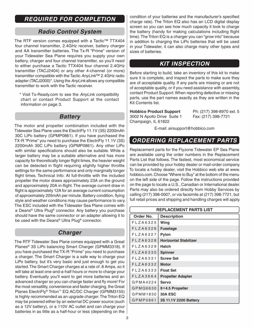
Radio Control SystemThe RTF version comes equipped with a Tactic™ TTX404 four channel transmitter, 2.4GHz receiver, battery charger and AA transmitter batteries. The Tx-R “Prime” version of your Tidewater Sea Plane requires you supply your own battery, charger and four channel transmitter, so you’ll need to either purchase a Tactic TTX404 four channel 2.4GHz transmitter (TACJ2404) or any other 4-channel (or more) transmitter compatible with the Tactic AnyLink™ 2.4GHz radio adapter (TACJ2000)*. Using the AnyLink allows any compatible transmitter to work with the Tactic receiver.
* Visit Tx-Ready.com to see the AnyLink compatibility chart or contact Product Support at the contact information on page 3.
BatteryThe motor and propeller combination included with the Tidewater Sea Plane uses the ElectriFly 11.1V (3S) 2200mAh 30C LiPo battery (GPMP0861). If you have purchased the TX-R “Prime” you need to purchase the ElectriFly 11.1V (3S) 2200mAh 30C LiPo battery (GPMP0861). Any other LiPo with similar specifi cations should also be suitable. While a larger battery may be a suitable alternative and has more capacity for theoretically longer fl ight times, the heavier weight can be detected in fl ight requiring slightly higher throttle settings for the same performance and only marginally longer fl ight times. Technical Info: At full-throttle with the included propeller the motor draws approximately 23A on the ground and approximately 20A in-fl ight. The average current draw in fl ight is approximately 12A for an average current consumption of approximately 205mAh per minute. Battery condition, fl ying style and weather conditions may cause performance to vary. The ESC included with the Tidewater Sea Plane comes with a Deans® Ultra Plug® connector. Any battery you purchase should have the same connector or an adapter allowing it to be used with the Deans® Ultra Plug® connector.
ChargerThe RTF Tidewater Sea Plane comes equipped with a Great Planes® 3S LiPo balancing Smart Charger (GPMM3318). If you have purchased the TX-R “Prime” you need to purchase a charger. The Smart Charger is a safe way to charge your LiPo battery, but it’s very basic and just enough to get you started. The Smart Charger charges at a rate of .8 Amps, so it will take at least one-and-a-half hours or more to charge your battery. Eventually you’ll want to get more batteries and an advanced charger so you can charge faster and fl y more! For the most versatility, convenience and faster charging, the Great Planes ElectriFly® Triton™ EQ AC/DC Charger (GPMM3155) is highly recommended as an upgrade charger. The Triton EQ may be powered either by an external DC power source (such as a 12V battery), or a 110V AC outlet and can charge your batteries in as little as a half-hour or less (depending on the
condition of your batteries and the manufacturer’s specifi ed charge rate). The Triton EQ also has an LCD digital display screen so you can see how much capacity it took to charge the battery (handy for making calculations including fl ight time). The Triton EQ is a charger you can “grow into” because in addition to charging the LiPo batteries that will be used in your Tidewater, it can also charge many other types and sizes of batteries.
KIT INSPECTIONBefore starting to build, take an inventory of this kit to make sure it is complete, and inspect the parts to make sure they are of acceptable quality. If any parts are missing or are not of acceptable quality, or if you need assistance with assembly, contact Product Support. When reporting defective or missing parts, use the part names exactly as they are written in the Kit Contents list.
Hobbico Product Support Ph: (217) 398-8970 ext. 53002 N Apollo Drive Suite 1 Fax: (217) 398-7721Champaign, IL 61822
E-mail: [email protected]
ORDERING REPLACEMENT PARTSReplacement parts for the Flyzone Tidewater EP Sea Plane are available using the order numbers in the Replacement Parts List that follows. The fastest, most economical service can be provided by your hobby dealer or mail-order company. To locate a hobby dealer, visit the Hobbico web site at www.hobbico.com. Choose “Where to Buy” at the bottom of the menu on the left side of the page. Follow the instructions provided on the page to locate a U.S., Canadian or International dealer. Parts may also be ordered directly from Hobby Services by calling (217) 398-0007, or via facsimile at (217) 398-7721, but full retail prices and shipping and handling charges will apply.
Order No. Description
REPLACEMENT PARTS LIST
Wing
Fuselage
Pylon
Horizontal Stabilizer
Hatch
Spinner
Screw Set
Motor
Float Set
Propeller Adapter
Servo
9 4.5 Propeller
30A ESC
3S 11.1V 2200 Battery
F L Z A 6 3 2 5
F L Z A 6 3 2 6
F L Z A 6 3 2 7
F L Z A 6 3 2 8
F L Z A 6 3 2 9
F L Z A 6 3 3 0
F L Z A 6 3 3 1
F L Z A 6 3 3 2
F L Z A 6 3 3 3
F L Z A 3 6 6 4
G P M A 4 2 2 4
G P M Q 6 6 3 0
G P M M 1 8 3 0
G P M P 0 8 6 1
4
ASSEMBLE THE MODELBefore starting to assemble the Tidewater Sea Plane, we recommend charging the fl ight battery. Then, when you are ready to setup the radio system, the fl ight battery can be used to power the receiver. Refer to the charging instructions on page 9.
Assemble the Fuselage
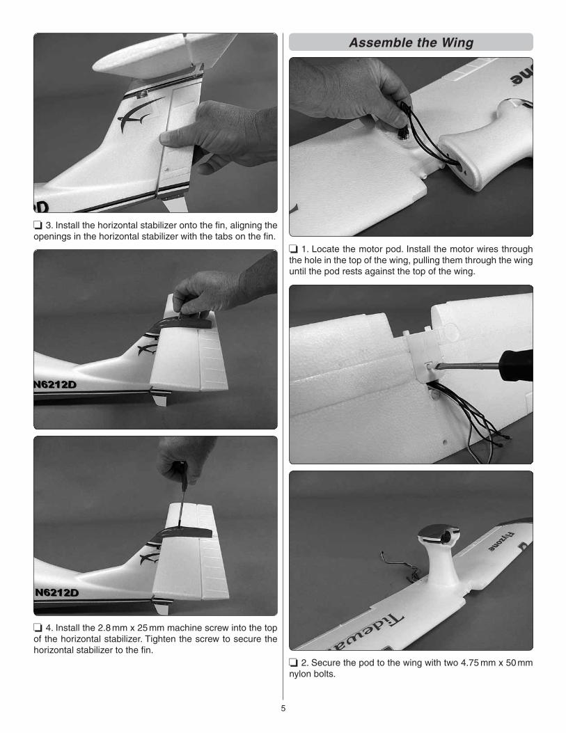
❏ 1. Insert the “z-bend” end of the elevator pushrod wire into the outer hole of the servo arm.
❏ 2. A brass screw lock connector is pre-installed in the bottom of the elevator. Loosen the screw and slide the screw lock connector onto the wire.
4
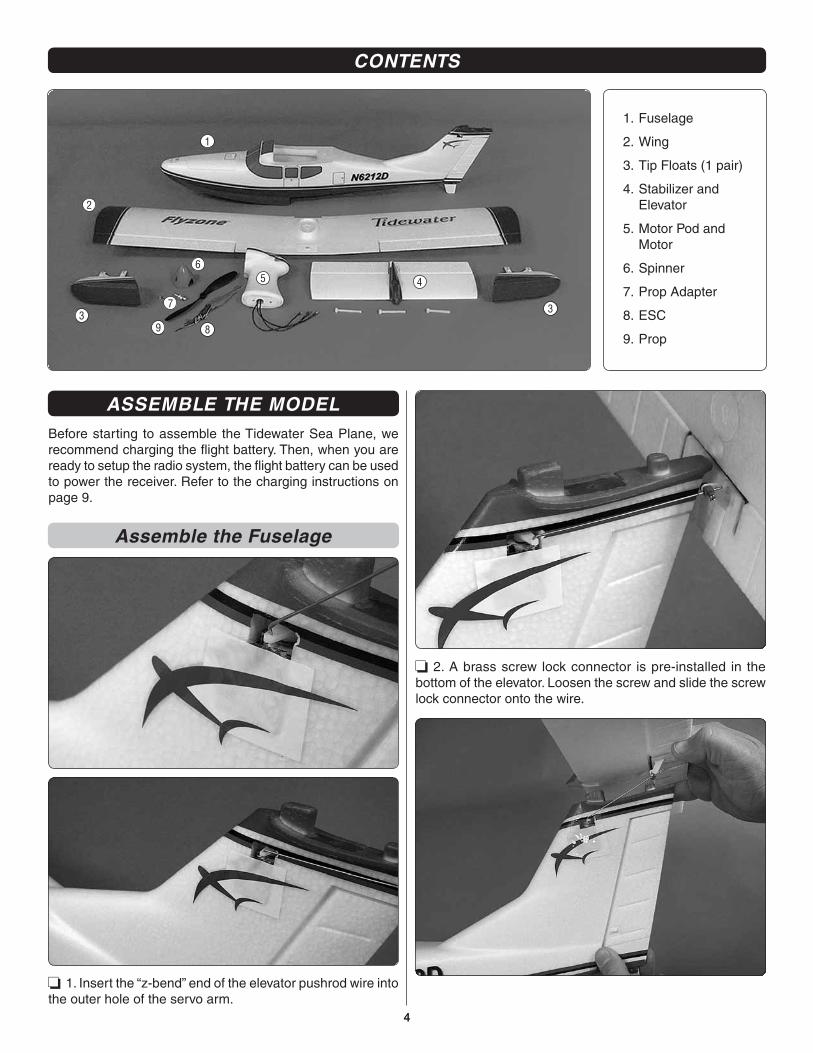
CONTENTS
1
6
89
2
4
73
3
5
1. Fuselage
2. Wing
3. Tip Floats (1 pair)
4. Stabilizer and Elevator
5. Motor Pod and Motor
6. Spinner
7. Prop Adapter
8. ESC
9. Prop
5
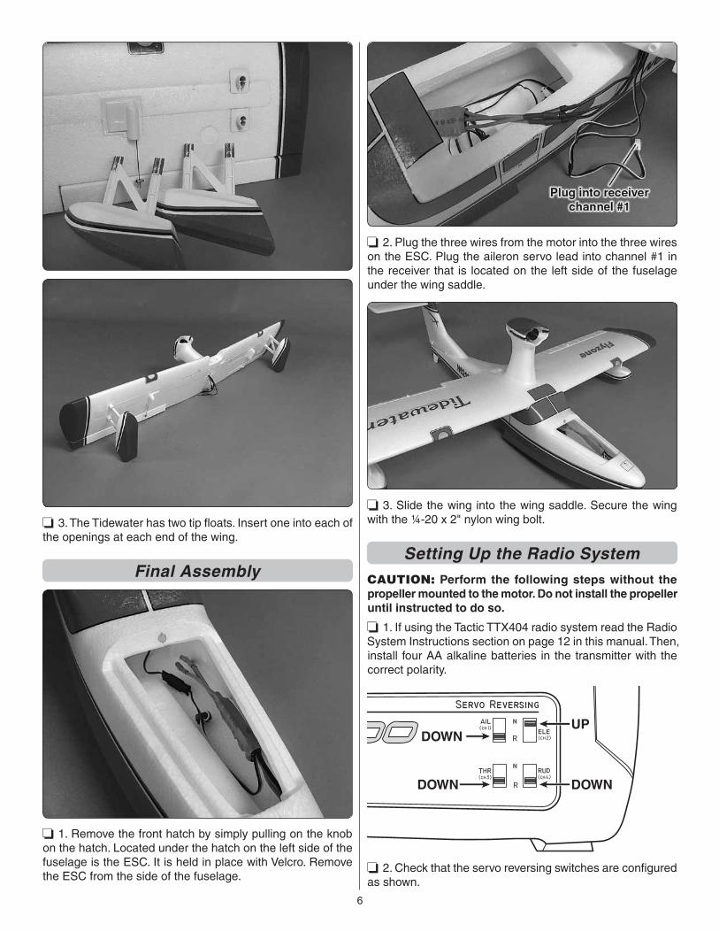
❏ 3. Install the horizontal stabilizer onto the fi n, aligning the openings in the horizontal stabilizer with the tabs on the fi n.
❏ 4. Install the 2.8 mm x 25 mm machine screw into the top of the horizontal stabilizer. Tighten the screw to secure the horizontal stabilizer to the fi n.
Assemble the Wing
❏ 1. Locate the motor pod. Install the motor wires through the hole in the top of the wing, pulling them through the wing until the pod rests against the top of the wing.
❏ 2. Secure the pod to the wing with two 4.75 mm x 50 mm nylon bolts.
6
❏ 3. The Tidewater has two tip fl oats. Insert one into each of the openings at each end of the wing.
Final Assembly
❏ 1. Remove the front hatch by simply pulling on the knob on the hatch. Located under the hatch on the left side of the fuselage is the ESC. It is held in place with Velcro. Remove the ESC from the side of the fuselage.
❏ 2. Plug the three wires from the motor into the three wires on the ESC. Plug the aileron servo lead into channel #1 in the receiver that is located on the left side of the fuselage under the wing saddle.
❏ 3. Slide the wing into the wing saddle. Secure the wing with the ¼-20 x 2" nylon wing bolt.
Setting Up the Radio SystemCAUTION: Perform the following steps without the propeller mounted to the motor. Do not install the propeller until instructed to do so.
❏ 1. If using the Tactic TTX404 radio system read the Radio System Instructions section on page 12 in this manual. Then, install four AA alkaline batteries in the transmitter with the correct polarity.
UPDOWN
DOWNDOWN
❏ 2. Check that the servo reversing switches are confi gured as shown.
7
❏ 3. Position the throttle stick (left stick) to idle (all the way down) and switch on the transmitter. The power indicator light should be glowing a steady red. A fl ashing red light and an audible tone indicates low voltage. If this happens, replace the batteries before connecting the fl ight battery.
❏ 4. Center the aileron, elevator, throttle and rudder trims on the transmitter by listening to the beeps. You will hear a low, short beep each time you bump the trim. When you hear one high, short beep the trim is centered. Experiment running the trim to the limits a few times to familiarize yourself with the trims. When fi nished, return all the trims to center. Before connecting the battery to the plane, be sure that you do not have the prop installed.
❏ 5. With the transmitter still switched on, connect the LiPo motor battery to the electronic speed control. The motor will produce a low tone. Moving the right stick on the transmitter up and down will move the elevator on the plane up and down. If the motor does not beep and the elevator does not move, the receiver will need to be bound to the transmitter.
❏ 6. The receiver does not need to be removed from the fuselage to bind it to the transmitter. Make sure the throttle stick is down in the idle or off position and the transmitter is switched on. Insert a small screwdriver or paperclip through the hole marked “Bind” and press the pushbutton until the LED on the receiver glows red and then turns off after about one second. Then, release the bind button. If the binding is successful, the LED on the receiver will fl ash once and then remain ON.
❏ 7. Make sure the motor brake function in the ESC is deactivated. When you advance the throttle stick, the motor should turn. When you bring the throttle stick all the way back down, the motor should come to a coasting stop. If the motor stops quickly, the brake is on.
❏ 8. When looking at the motor from the front of the airplane the motor should be turning counter-clockwise. If it is not, simply unplug any two of the wires from the motor to the speed control (ESC) and switch the two wires.
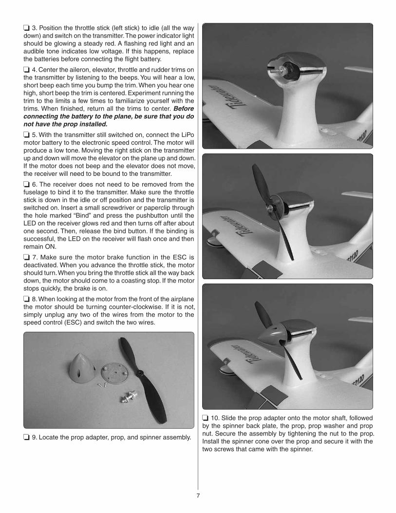
❏ 9. Locate the prop adapter, prop, and spinner assembly.
❏ 10. Slide the prop adapter onto the motor shaft, followed by the spinner back plate, the prop, prop washer and prop nut. Secure the assembly by tightening the nut to the prop. Install the spinner cone over the prop and secure it with the two screws that came with the spinner.
8
GET THE MODEL READY TO FLY
Check the ControlsThe next few steps will require working on the model with the radio turned on and power to the motor. To prevent an accident or possible injury, temporarily remove the spinner cone and propeller. If you are not familiar with the functions of your transmitter refer to the instructions on page 12 of this manual.
❏ 1. Turn on the transmitter and lower the throttle stick all the way. Center all the trims and connect the battery to the ESC. If everything is working correctly you should hear one, low pitch beep from the ESC (“beep”). This signals that the motor is not yet “armed,” but is ready to be armed and is receiving a signal from the receiver. To arm the motor when ready to fl y, advance the throttle stick all the way, listen for another, single beep (“beep”), then return the throttle stick to off and hear two more beeps (“beep, beep”). Now the motor will turn whenever the throttle stick is advanced. If, when you connect the battery you hear consecutive, higher pitch beeps (“BEEP. BEEP. BEEP. BEEP…”) this indicates that the throttle stick is not all the way down to the “off” position, or that the throttle servo direction is reversed. To fi x this, return the throttle stick to off, or disconnect the battery and reverse the throttle servo direction in transmitter. If you hear consecutive, fast, loud beeps (“BEEP! BEEP! BEEP! BEEP!”), this indicates that the ESC is not receiving a signal from the receiver. Either the receiver is not bound to the transmitter, or the transmitter is off. Once you have the motor fi gured out and set correctly continue to set up the rest of the controls:
❏ 2. Use the transmitter to make sure all the controls respond in the correct direction.
❏ 3. Take each screw out of the screw-lock connectors on all the pushrods and lightly “wet” the threads of the screws with threadlocker. With the radio on and the controls centered, reinstall and tighten the screws with the control surfaces and nose wheel centered.
FULLTHROTTLE
RUDDERMOVESRIGHT
ELEVATORMOVES DOWN
RIGHT AILERONMOVES UP
LEFT AILERONMOVES DOWN
4-CHANNEL RADIO SET UP (STANDARD MODE 2)
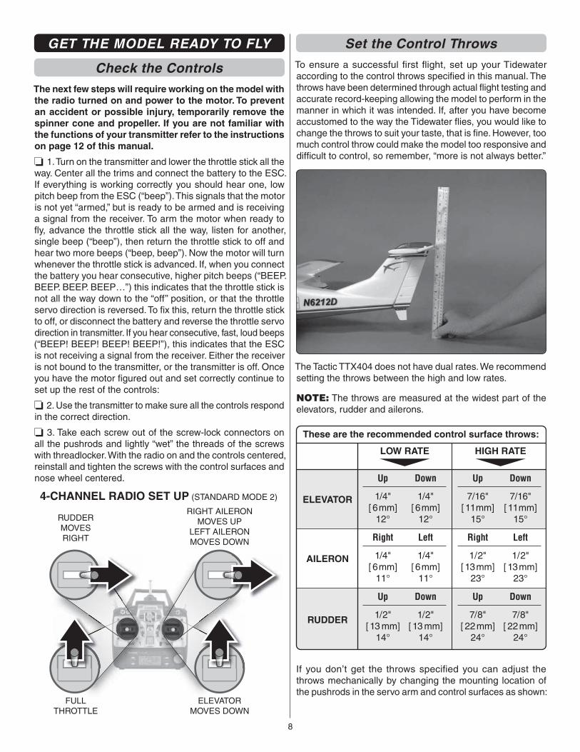
Set the Control ThrowsTo ensure a successful fi rst fl ight, set up your Tidewater according to the control throws specifi ed in this manual. The throws have been determined through actual fl ight testing and accurate record-keeping allowing the model to perform in the manner in which it was intended. If, after you have become accustomed to the way the Tidewater fl ies, you would like to change the throws to suit your taste, that is fi ne. However, too much control throw could make the model too responsive and diffi cult to control, so remember, “more is not always better.”
The Tactic TTX404 does not have dual rates. We recommend setting the throws between the high and low rates.
NOTE: The throws are measured at the widest part of the elevators, rudder and ailerons.
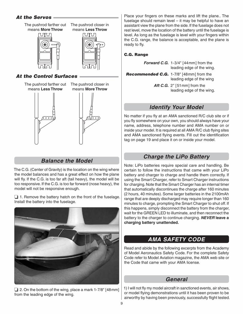
These are the recommended control surface throws:
ELEVATOR
LOW RATE
AILERON
RUDDER
HIGH RATE
1/4"[ 6mm]
12°
Up
1/4"[ 6mm]
11°
Right
1/2"[ 13 mm]
14°
Up
7/16"[ 11mm]
15°
Up
1/2"[ 13mm]
23°
Right
7/8"[ 22mm]
24°
Up
1/4"[ 6mm]
12°
Down
1/4"[ 6mm]
11°
Left
1/2"[ 13 mm]
14°
Down
7/16"[ 11mm]
15°
Down
1/2"[ 13mm]
23°
Left
7/8"[ 22mm]
24°
Down
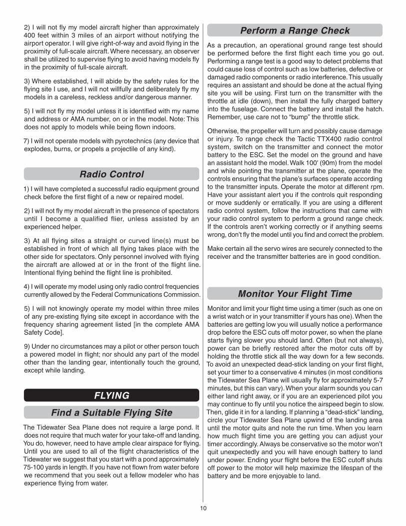
If you don’t get the throws specifi ed you can adjust the throws mechanically by changing the mounting location of the pushrods in the servo arm and control surfaces as shown:
9
The pushrod farther outmeans More Throw
The pushrod closer inmeans Less Throw
The pushrod farther outmeans Less Throw
The pushrod closer inmeans More Throw
At the Servos
At the Control Surfaces
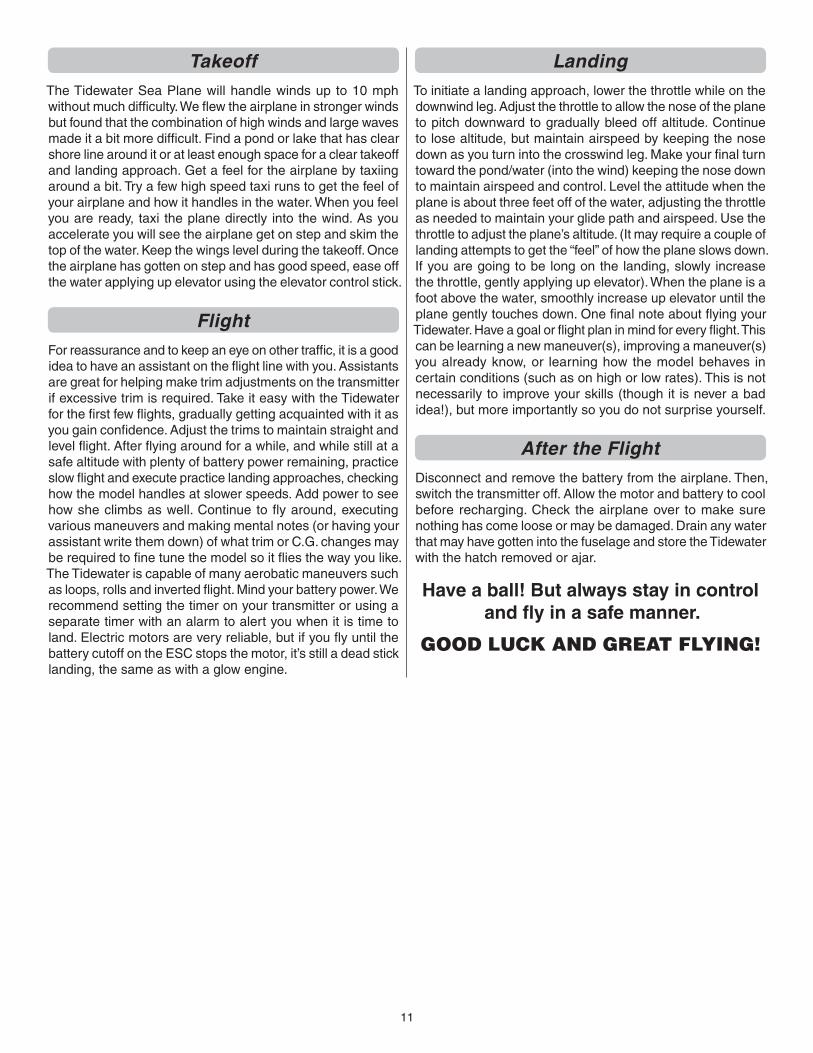
Balance the ModelThe C.G. (Center of Gravity) is the location on the wing where the model balances and has a great effect on how the plane will fl y. If the C.G. is too far aft (tail heavy), the model will be too responsive. If the C.G. is too far forward (nose heavy), the model will not be responsive enough.
❏ 1. Remove the battery hatch on the front of the fuselage. Install the battery into the fuselage.
❏ 2. On the bottom of the wing, place a mark 1-7/8" [48mm] from the leading edge of the wing.
Place your fi ngers on these marks and lift the plane.. The fuselage should remain level – it may be helpful to have an assistant view the plane from the side. If the fuselage does not rest level, move the location of the battery until the fuselage is level. As long as the fuselage is level with your fi ngers within the C.G. range, the balance is acceptable, and the plane is ready to fl y.
C.G. Range
Forward C.G. 1-3/4" [44mm] from the leading edge of the wing.
Recommended C.G. 1-7/8" [48mm] from the leading edge of the wing
Aft C.G. 2" [51mm] from the leading edge of the wing.
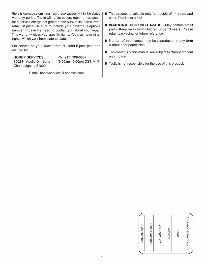
Identify Your ModelNo matter if you fl y at an AMA sanctioned R/C club site or if you fl y somewhere on your own, you should always have your name, address, telephone number and AMA number on or inside your model. It is required at all AMA R/C club fl ying sites and AMA sanctioned fl ying events. Fill out the identifi cation tag on page 19 and place it on or inside your model.
Charge the LiPo BatteryNote: LiPo batteries require special care and handling. Be certain to follow the instructions that came with your LiPo battery and charger to charge and handle them correctly. If using the Smart Charger, refer to Smart Charger instructions for charging. Note that the Smart Charger has an internal timer that automatically discontinues the charge after 160 minutes (2 hours, 40 minutes). Some larger batteries in the 2100mAh range that are deeply discharged may require longer than 160 minutes to charge, prompting the Smart Charger to shut off. If this happens, simply disconnect the battery from the charger, wait for the GREEN LED to illuminate, and then reconnect the battery to the charger to continue charging. NEVER leave a charging battery unattended.
AMA SAFETY CODERead and abide by the following excerpts from the Academy of Model Aeronautics Safety Code. For the complete Safety Code refer to Model Aviation magazine, the AMA web site or the Code that came with your AMA license.
General1) I will not fl y my model aircraft in sanctioned events, air shows, or model fl ying demonstrations until it has been proven to be airworthy by having been previously, successfully fl ight tested.
10
2) I will not fl y my model aircraft higher than approximately 400 feet within 3 miles of an airport without notifying the airport operator. I will give right-of-way and avoid fl ying in the proximity of full-scale aircraft. Where necessary, an observer shall be utilized to supervise fl ying to avoid having models fl y in the proximity of full-scale aircraft.
3) Where established, I will abide by the safety rules for the fl ying site I use, and I will not willfully and deliberately fl y my models in a careless, reckless and/or dangerous manner.
5) I will not fl y my model unless it is identifi ed with my name and address or AMA number, on or in the model. Note: This does not apply to models while being fl own indoors.
7) I will not operate models with pyrotechnics (any device that explodes, burns, or propels a projectile of any kind).
Radio Control1) I will have completed a successful radio equipment ground check before the fi rst fl ight of a new or repaired model.
2) I will not fl y my model aircraft in the presence of spectators until I become a qualified flier, unless assisted by an experienced helper.
3) At all fl ying sites a straight or curved line(s) must be established in front of which all fl ying takes place with the other side for spectators. Only personnel involved with fl ying the aircraft are allowed at or in the front of the fl ight line. Intentional fl ying behind the fl ight line is prohibited.
4) I will operate my model using only radio control frequencies currently allowed by the Federal Communications Commission.
5) I will not knowingly operate my model within three miles of any pre-existing fl ying site except in accordance with the frequency sharing agreement listed [in the complete AMA Safety Code].
9) Under no circumstances may a pilot or other person touch a powered model in fl ight; nor should any part of the model other than the landing gear, intentionally touch the ground, except while landing.
FLYING
Find a Suitable Flying SiteThe Tidewater Sea Plane does not require a large pond. It does not require that much water for your take-off and landing. You do, however, need to have ample clear airspace for fl ying. Until you are used to all of the fl ight characteristics of the Tidewater we suggest that you start with a pond approximately 75-100 yards in length. If you have not fl own from water before we recommend that you seek out a fellow modeler who has experience fl ying from water.
Perform a Range CheckAs a precaution, an operational ground range test should be performed before the fi rst fl ight each time you go out. Performing a range test is a good way to detect problems that could cause loss of control such as low batteries, defective or damaged radio components or radio interference. This usually requires an assistant and should be done at the actual fl ying site you will be using. First turn on the transmitter with the throttle at idle (down), then install the fully charged battery into the fuselage. Connect the battery and install the hatch. Remember, use care not to “bump” the throttle stick.
Otherwise, the propeller will turn and possibly cause damage or injury. To range check the Tactic TTX400 radio control system, switch on the transmitter and connect the motor battery to the ESC. Set the model on the ground and have an assistant hold the model. Walk 100' (90m) from the model and while pointing the transmitter at the plane, operate the controls ensuring that the plane’s surfaces operate according to the transmitter inputs. Operate the motor at different rpm. Have your assistant alert you if the controls quit responding or move suddenly or erratically. If you are using a different radio control system, follow the instructions that came with your radio control system to perform a ground range check. If the controls aren’t working correctly or if anything seems wrong, don’t fl y the model until you fi nd and correct the problem.
Make certain all the servo wires are securely connected to the receiver and the transmitter batteries are in good condition.
Monitor Your Flight TimeMonitor and limit your fl ight time using a timer (such as one on a wrist watch or in your transmitter if yours has one). When the batteries are getting low you will usually notice a performance drop before the ESC cuts off motor power, so when the plane starts fl ying slower you should land. Often (but not always), power can be briefl y restored after the motor cuts off by holding the throttle stick all the way down for a few seconds. To avoid an unexpected dead-stick landing on your fi rst fl ight, set your timer to a conservative 4 minutes (in most conditions the Tidewater Sea Plane will usually fl y for approximately 5-7 minutes, but this can vary). When your alarm sounds you can either land right away, or if you are an experienced pilot you may continue to fl y until you notice the airspeed begin to slow. Then, glide it in for a landing. If planning a “dead-stick” landing, circle your Tidewater Sea Plane upwind of the landing area until the motor quits and note the run time. When you learn how much fl ight time you are getting you can adjust your timer accordingly. Always be conservative so the motor won’t quit unexpectedly and you will have enough battery to land under power. Ending your fl ight before the ESC cutoff shuts off power to the motor will help maximize the lifespan of the battery and be more enjoyable to land.
11
TakeoffThe Tidewater Sea Plane will handle winds up to 10 mph without much diffi culty. We fl ew the airplane in stronger winds but found that the combination of high winds and large waves made it a bit more diffi cult. Find a pond or lake that has clear shore line around it or at least enough space for a clear takeoff and landing approach. Get a feel for the airplane by taxiing around a bit. Try a few high speed taxi runs to get the feel of your airplane and how it handles in the water. When you feel you are ready, taxi the plane directly into the wind. As you accelerate you will see the airplane get on step and skim the top of the water. Keep the wings level during the takeoff. Once the airplane has gotten on step and has good speed, ease off the water applying up elevator using the elevator control stick.
FlightFor reassurance and to keep an eye on other traffi c, it is a good idea to have an assistant on the fl ight line with you. Assistants are great for helping make trim adjustments on the transmitter if excessive trim is required. Take it easy with the Tidewater for the fi rst few fl ights, gradually getting acquainted with it as you gain confi dence. Adjust the trims to maintain straight and level fl ight. After fl ying around for a while, and while still at a safe altitude with plenty of battery power remaining, practice slow fl ight and execute practice landing approaches, checking how the model handles at slower speeds. Add power to see how she climbs as well. Continue to fl y around, executing various maneuvers and making mental notes (or having your assistant write them down) of what trim or C.G. changes may be required to fi ne tune the model so it fl ies the way you like. The Tidewater is capable of many aerobatic maneuvers such as loops, rolls and inverted fl ight. Mind your battery power. We recommend setting the timer on your transmitter or using a separate timer with an alarm to alert you when it is time to land. Electric motors are very reliable, but if you fl y until the battery cutoff on the ESC stops the motor, it’s still a dead stick landing, the same as with a glow engine.
LandingTo initiate a landing approach, lower the throttle while on the downwind leg. Adjust the throttle to allow the nose of the plane to pitch downward to gradually bleed off altitude. Continue to lose altitude, but maintain airspeed by keeping the nose down as you turn into the crosswind leg. Make your fi nal turn toward the pond/water (into the wind) keeping the nose down to maintain airspeed and control. Level the attitude when the plane is about three feet off of the water, adjusting the throttle as needed to maintain your glide path and airspeed. Use the throttle to adjust the plane’s altitude. (It may require a couple of landing attempts to get the “feel” of how the plane slows down. If you are going to be long on the landing, slowly increase the throttle, gently applying up elevator). When the plane is a foot above the water, smoothly increase up elevator until the plane gently touches down. One fi nal note about fl ying your Tidewater. Have a goal or fl ight plan in mind for every fl ight. This can be learning a new maneuver(s), improving a maneuver(s) you already know, or learning how the model behaves in certain conditions (such as on high or low rates). This is not necessarily to improve your skills (though it is never a bad idea!), but more importantly so you do not surprise yourself.
After the FlightDisconnect and remove the battery from the airplane. Then, switch the transmitter off. Allow the motor and battery to cool before recharging. Check the airplane over to make sure nothing has come loose or may be damaged. Drain any water that may have gotten into the fuselage and store the Tidewater with the hatch removed or ajar.
Have a ball! But always stay in control and fl y in a safe manner.
GOOD LUCK AND GREAT FLYING!
12
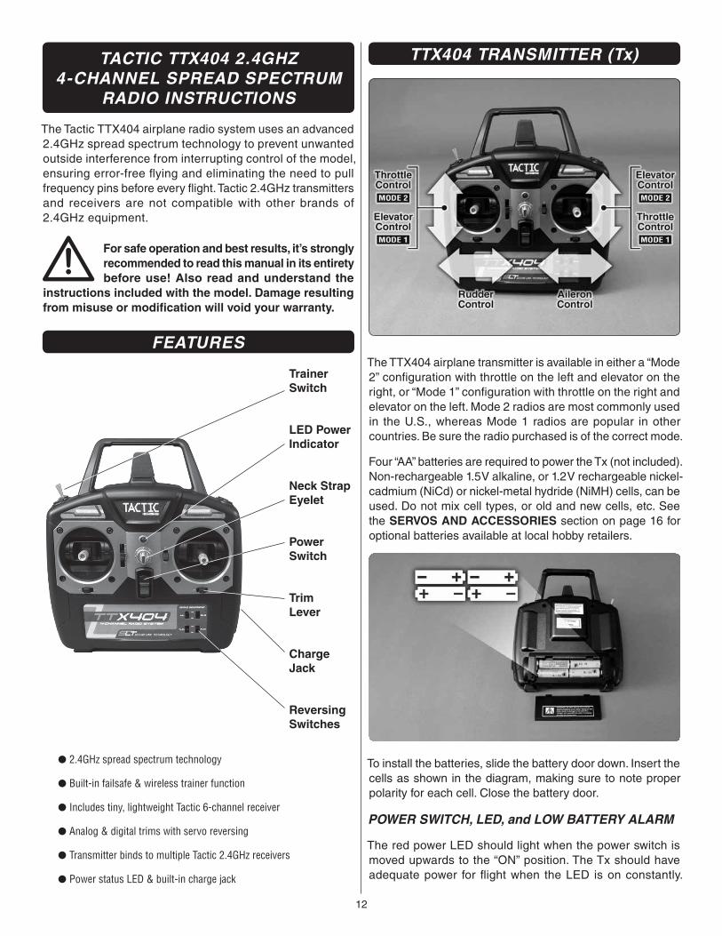
TACTIC TTX404 2.4GHZ4-CHANNEL SPREAD SPECTRUM
RADIO INSTRUCTIONS
The Tactic TTX404 airplane radio system uses an advanced 2.4GHz spread spectrum technology to prevent unwanted outside interference from interrupting control of the model, ensuring error-free fl ying and eliminating the need to pull frequency pins before every fl ight. Tactic 2.4GHz transmitters and receivers are not compatible with other brands of 2.4GHz equipment.
For safe operation and best results, it’s strongly recommended to read this manual in its entirety before use! Also read and understand the
instructions included with the model. Damage resulting from misuse or modifi cation will void your warranty.
FEATURES
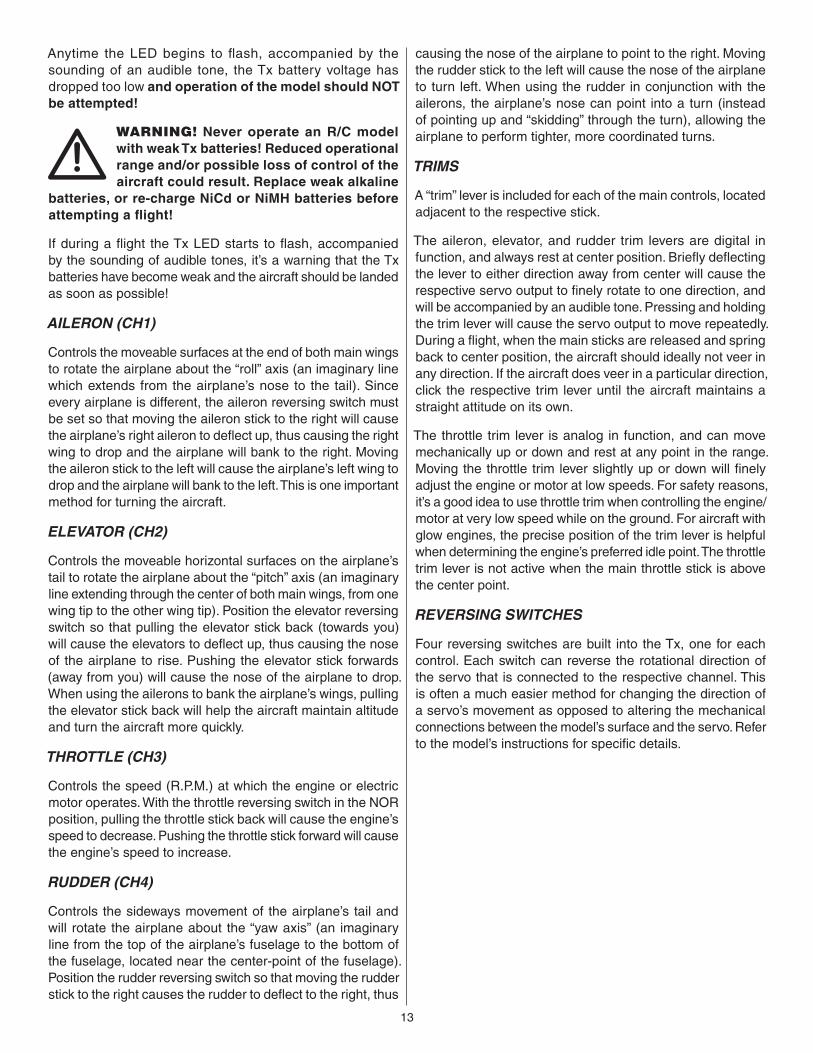
TrainerSwitch
LED PowerIndicator
PowerSwitch
ReversingSwitches
Neck StrapEyelet
TrimLever
ChargeJack
● 2.4GHz spread spectrum technology
● Built-in failsafe & wireless trainer function
● Includes tiny, lightweight Tactic 6-channel receiver
● Analog & digital trims with servo reversing
● Transmitter binds to multiple Tactic 2.4GHz receivers
● Power status LED & built-in charge jack
TTX404 TRANSMITTER (Tx)
The TTX404 airplane transmitter is available in either a “Mode 2” confi guration with throttle on the left and elevator on the right, or “Mode 1” confi guration with throttle on the right and elevator on the left. Mode 2 radios are most commonly used in the U.S., whereas Mode 1 radios are popular in other countries. Be sure the radio purchased is of the correct mode.
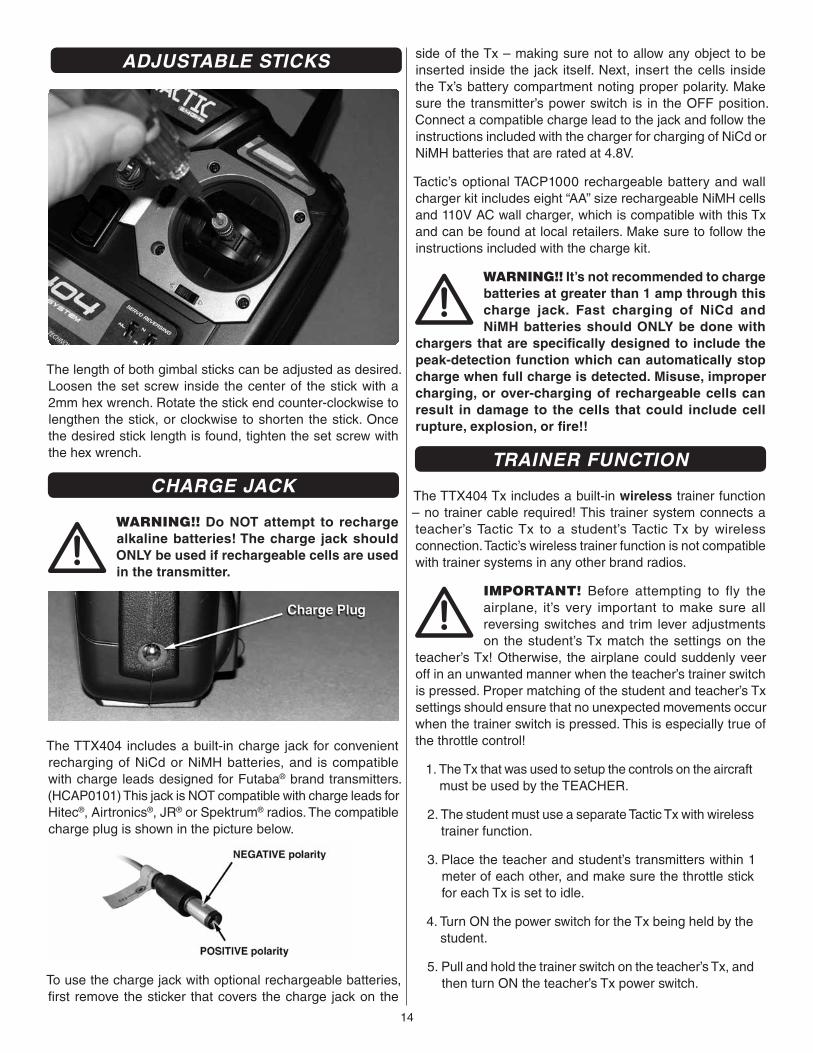
Four “AA” batteries are required to power the Tx (not included). Non-rechargeable 1.5V alkaline, or 1.2V rechargeable nickel-cadmium (NiCd) or nickel-metal hydride (NiMH) cells, can be used. Do not mix cell types, or old and new cells, etc. See the SERVOS AND ACCESSORIES section on page 16 for optional batteries available at local hobby retailers.
To install the batteries, slide the battery door down. Insert the cells as shown in the diagram, making sure to note proper polarity for each cell. Close the battery door.
POWER SWITCH, LED, and LOW BATTERY ALARM
The red power LED should light when the power switch is moved upwards to the “ON” position. The Tx should have adequate power for fl ight when the LED is on constantly.
13
Anytime the LED begins to fl ash, accompanied by the sounding of an audible tone, the Tx battery voltage has dropped too low and operation of the model should NOT be attempted!
WARNING! Never operate an R/C model with weak Tx batteries! Reduced operational range and/or possible loss of control of the aircraft could result. Replace weak alkaline
batteries, or re-charge NiCd or NiMH batteries before attempting a fl ight!
If during a fl ight the Tx LED starts to fl ash, accompanied by the sounding of audible tones, it’s a warning that the Tx batteries have become weak and the aircraft should be landed as soon as possible!
AILERON (CH1)
Controls the moveable surfaces at the end of both main wings to rotate the airplane about the “roll” axis (an imaginary line which extends from the airplane’s nose to the tail). Since every airplane is different, the aileron reversing switch must be set so that moving the aileron stick to the right will cause the airplane’s right aileron to defl ect up, thus causing the right wing to drop and the airplane will bank to the right. Moving the aileron stick to the left will cause the airplane’s left wing to drop and the airplane will bank to the left. This is one important method for turning the aircraft.
ELEVATOR (CH2)
Controls the moveable horizontal surfaces on the airplane’s tail to rotate the airplane about the “pitch” axis (an imaginary line extending through the center of both main wings, from one wing tip to the other wing tip). Position the elevator reversing switch so that pulling the elevator stick back (towards you) will cause the elevators to defl ect up, thus causing the nose of the airplane to rise. Pushing the elevator stick forwards (away from you) will cause the nose of the airplane to drop. When using the ailerons to bank the airplane’s wings, pulling the elevator stick back will help the aircraft maintain altitude and turn the aircraft more quickly.
THROTTLE (CH3)
Controls the speed (R.P.M.) at which the engine or electric motor operates. With the throttle reversing switch in the NOR position, pulling the throttle stick back will cause the engine’s speed to decrease. Pushing the throttle stick forward will cause the engine’s speed to increase.
RUDDER (CH4)
Controls the sideways movement of the airplane’s tail and will rotate the airplane about the “yaw axis” (an imaginary line from the top of the airplane’s fuselage to the bottom of the fuselage, located near the center-point of the fuselage). Position the rudder reversing switch so that moving the rudder stick to the right causes the rudder to defl ect to the right, thus
causing the nose of the airplane to point to the right. Moving the rudder stick to the left will cause the nose of the airplane to turn left. When using the rudder in conjunction with the ailerons, the airplane’s nose can point into a turn (instead of pointing up and “skidding” through the turn), allowing the airplane to perform tighter, more coordinated turns.
TRIMS
A “trim” lever is included for each of the main controls, located adjacent to the respective stick.
The aileron, elevator, and rudder trim levers are digital in function, and always rest at center position. Briefl y defl ecting the lever to either direction away from center will cause the respective servo output to fi nely rotate to one direction, and will be accompanied by an audible tone. Pressing and holding the trim lever will cause the servo output to move repeatedly. During a fl ight, when the main sticks are released and spring back to center position, the aircraft should ideally not veer in any direction. If the aircraft does veer in a particular direction, click the respective trim lever until the aircraft maintains a straight attitude on its own.
The throttle trim lever is analog in function, and can move mechanically up or down and rest at any point in the range. Moving the throttle trim lever slightly up or down will fi nely adjust the engine or motor at low speeds. For safety reasons, it’s a good idea to use throttle trim when controlling the engine/motor at very low speed while on the ground. For aircraft with glow engines, the precise position of the trim lever is helpful when determining the engine’s preferred idle point. The throttle trim lever is not active when the main throttle stick is above the center point.
REVERSING SWITCHES
Four reversing switches are built into the Tx, one for each control. Each switch can reverse the rotational direction of the servo that is connected to the respective channel. This is often a much easier method for changing the direction of a servo’s movement as opposed to altering the mechanical connections between the model’s surface and the servo. Refer to the model’s instructions for specifi c details.
14
ADJUSTABLE STICKS
The length of both gimbal sticks can be adjusted as desired. Loosen the set screw inside the center of the stick with a 2mm hex wrench. Rotate the stick end counter-clockwise to lengthen the stick, or clockwise to shorten the stick. Once the desired stick length is found, tighten the set screw with the hex wrench.
CHARGE JACK
WARNING!! Do NOT attempt to recharge alkaline batteries! The charge jack should ONLY be used if rechargeable cells are used in the transmitter.
The TTX404 includes a built-in charge jack for convenient recharging of NiCd or NiMH batteries, and is compatible with charge leads designed for Futaba® brand transmitters. (HCAP0101) This jack is NOT compatible with charge leads for Hitec®, Airtronics®, JR® or Spektrum® radios. The compatible charge plug is shown in the picture below.
To use the charge jack with optional rechargeable batteries, fi rst remove the sticker that covers the charge jack on the
side of the Tx – making sure not to allow any object to be inserted inside the jack itself. Next, insert the cells inside the Tx’s battery compartment noting proper polarity. Make sure the transmitter’s power switch is in the OFF position. Connect a compatible charge lead to the jack and follow the instructions included with the charger for charging of NiCd or NiMH batteries that are rated at 4.8V.
Tactic’s optional TACP1000 rechargeable battery and wall charger kit includes eight “AA” size rechargeable NiMH cells and 110V AC wall charger, which is compatible with this Tx and can be found at local retailers. Make sure to follow the instructions included with the charge kit.
WARNING!! It’s not recommended to charge batteries at greater than 1 amp through this charge jack. Fast charging of NiCd and NiMH batteries should ONLY be done with
chargers that are specifi cally designed to include the peak-detection function which can automatically stop charge when full charge is detected. Misuse, improper charging, or over-charging of rechargeable cells can result in damage to the cells that could include cell rupture, explosion, or fi re!!
TRAINER FUNCTION
The TTX404 Tx includes a built-in wireless trainer function – no trainer cable required! This trainer system connects a teacher’s Tactic Tx to a student’s Tactic Tx by wireless connection. Tactic’s wireless trainer function is not compatible with trainer systems in any other brand radios.
IMPORTANT! Before attempting to fly the airplane, it’s very important to make sure all reversing switches and trim lever adjustments on the student’s Tx match the settings on the
teacher’s Tx! Otherwise, the airplane could suddenly veer off in an unwanted manner when the teacher’s trainer switch is pressed. Proper matching of the student and teacher’s Tx settings should ensure that no unexpected movements occur when the trainer switch is pressed. This is especially true of the throttle control!
1. The Tx that was used to setup the controls on the aircraft must be used by the TEACHER.
2. The student must use a separate Tactic Tx with wireless trainer function.
3. Place the teacher and student’s transmitters within 1 meter of each other, and make sure the throttle stick for each Tx is set to idle.
4. Turn ON the power switch for the Tx being held by the student.
5. Pull and hold the trainer switch on the teacher’s Tx, and then turn ON the teacher’s Tx power switch.
15
6. The LED on the teacher’s Tx will fl ash 3 times to indicate it has become bound with the student’s Tx.
7. The teacher can then release his trainer switch.
8. Once both transmitters are bound together, power can be applied to the receiver to prepare for fl ight.
When the training session has ended, with the model on the ground and all power removed from the model, place both transmitters within 1 meter of each other and simply turn the power switch for both transmitters to the OFF position. This will terminate the wireless link between both transmitters. If additional training will be performed again, return to step 1 above to re-establish the wireless link between the teacher and student’s transmitters.
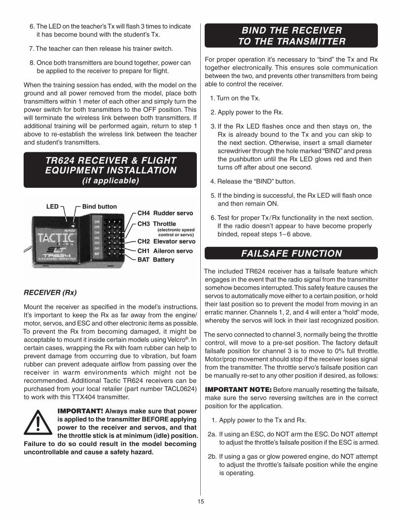
TR624 RECEIVER & FLIGHT EQUIPMENT INSTALLATION
(if applicable)
RECEIVER (Rx)
Mount the receiver as specifi ed in the model’s instructions. It’s important to keep the Rx as far away from the engine/motor, servos, and ESC and other electronic items as possible. To prevent the Rx from becoming damaged, it might be acceptable to mount it inside certain models using Velcro®. In certain cases, wrapping the Rx with foam rubber can help to prevent damage from occurring due to vibration, but foam rubber can prevent adequate airfl ow from passing over the receiver in warm environments which might not be recommended. Additional Tactic TR624 receivers can be purchased from your local retailer (part number TACL0624) to work with this TTX404 transmitter.
IMPORTANT! Always make sure that power is applied to the transmitter BEFORE applying power to the receiver and servos, and that the throttle stick is at minimum (idle) position.
Failure to do so could result in the model becoming uncontrollable and cause a safety hazard.
BIND THE RECEIVERTO THE TRANSMITTER
For proper operation it’s necessary to “bind” the Tx and Rx together electronically. This ensures sole communication between the two, and prevents other transmitters from being able to control the receiver.
1. Turn on the Tx.
2. Apply power to the Rx.
3. If the Rx LED fl ashes once and then stays on, the Rx is already bound to the Tx and you can skip to the next section. Otherwise, insert a small diameter screwdriver through the hole marked “BIND” and press the pushbutton until the Rx LED glows red and then turns off after about one second.
4. Release the “BIND” button.
5. If the binding is successful, the Rx LED will fl ash once and then remain ON.
6. Test for proper Tx /Rx functionality in the next section. If the radio doesn’t appear to have become properly binded, repeat steps 1–6 above.
FAILSAFE FUNCTION
The included TR624 receiver has a failsafe feature which engages in the event that the radio signal from the transmitter somehow becomes interrupted. This safety feature causes the servos to automatically move either to a certain position, or hold their last position so to prevent the model from moving in an erratic manner. Channels 1, 2, and 4 will enter a “hold” mode, whereby the servos will lock in their last recognized position.
The servo connected to channel 3, normally being the throttle control, will move to a pre-set position. The factory default failsafe position for channel 3 is to move to 0% full throttle. Motor/prop movement should stop if the receiver loses signal from the transmitter. The throttle servo’s failsafe position can be manually re-set to any other position if desired, as follows:
IMPORTANT NOTE: Before manually resetting the failsafe, make sure the servo reversing switches are in the correct position for the application.
1. Apply power to the Tx and Rx.
2a. If using an ESC, do NOT arm the ESC. Do NOT attempt to adjust the throttle’s failsafe position if the ESC is armed.
2b. If using a gas or glow powered engine, do NOT attempt to adjust the throttle’s failsafe position while the engine is operating.
16
3. Move the Tx throttle stick to the desired position for the throttle control to move if the Rx goes to failsafe.
4. Press and hold the “Bind” button on the receiver, and the Rx’s LED should blink twice. Release the Bind button, and the receiver’s LED should turn on (stop fl ashing). The Tx and Rx should now be bound, with the throttle failsafe in the new position as set above.
NOTE: If you’re using an ESC which has a signal loss feature, the pre-set failsafe position is irrelevant as the signal loss feature will cease the throttle operation if the signal is lost.
SYSTEM CHECK AND OPERATION
WARNING! During all pre-fl ight preparations with the aircraft on the ground, make sure the throttle stick remains at the minimum position and do not stand the Tx upright on the ground. Carefully
lay the Tx on its back on the ground to prevent it from falling over and possibly dislodging the throttle stick from the low position which would create a safety hazard. Make sure all devices are properly mounted inside the model, and all wiring connections are solid to prevent them from easily becoming dislodged during normal fl ight. It’s best to check the system with the propeller removed from the aircraft.
1. Once all connections are made, check the general operation of the radio and all other components before attempting a fl ight.
2. Move the Tx throttle stick to the minimum (idle) position.
3. Turn on the Tx, and then the Rx.
4. Make sure all controls are operating in the proper direction. If any servo is turning in the wrong direction, change the position of the reversing switch for that particular channel.
5. With both sticks at center position, move the trim levers for the aileron, elevator, and rudder channels so each respective control surface is perfectly aligned with the main surface. For example: When the aileron trim lever is in the center position, it’s best that the trailing edge of the aileron is aligned with the trailing edge of the wing itself (not above or below the wing’s trailing edge).
6. Make sure that movements of the throttle stick result in an equal adjustment of the throttle in the model. Depending on whether the airplane is electric or glow powered:
a. Electric: confi rm that when the throttle stick is at maximum position the electronic speed control gives the appropriate indications (LED and/or audible indicators) for full forward fl ight. And, when the throttle stick is at minimum position the electronic speed control gives the appropriate indications for “off” or no motor rotation.
b. Glow: confi rm that when the throttle stick is at maximum position the mechanical linkage to the engine allows the engine to be at full throttle. And, when the throttle stick is at minimum position and the throttle trim lever is moved to minimum position, the engine stops completely.
7. Perform a “range check.” The “range” is the safe operating distance from the Tx to the Rx, and should be as far as you can clearly see the model. With the assistance of another person, place the aircraft on the ground and walk 100 feet (30m) away from the model. With the Tx pointed directly at the model, operate the transmitter’s controls, and ensure the movement of all surfaces is according to the movement of the transmitter.
8. Anytime power is to be removed from the radio system, it’s important to shut down power in the aircraft fi rst. Otherwise, the aircraft could become out of control and cause a safety hazard! Move the throttle stick and throttle trim lever to minimum position to stop the glow engine or shut down the ESC. Once the propeller has stopped rotating, shut off the ON/OFF power switch in the model, and disconnect the power battery from the ESC in electric airplanes. Then turn off the power switch in the Tx.
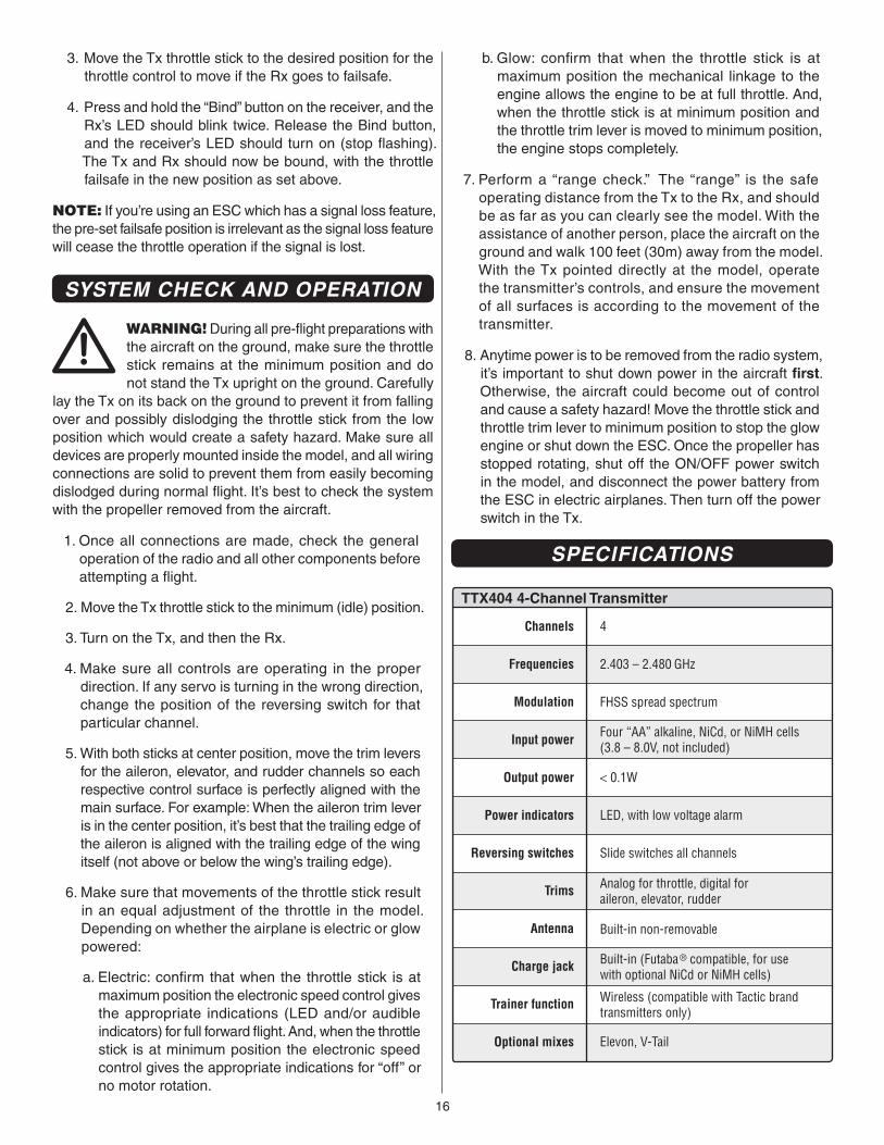
SPECIFICATIONS
TTX404 4-Channel Transmitter
Channels 4
Frequencies 2.403 – 2.480 GHz
Modulation FHSS spread spectrum
Input power Four “AA” alkaline, NiCd, or NiMH cells(3.8 – 8.0V, not included)
Output power < 0.1W
Power indicators LED, with low voltage alarm
Reversing switches Slide switches all channels
Trims Analog for throttle, digital foraileron, elevator, rudder
Antenna Built-in non-removable
Optional mixes Elevon, V-Tail
Trainer function Wireless (compatible with Tactic brandtransmitters only)
Charge jack Built-in (Futaba® compatible, for usewith optional NiCd or NiMH cells)
17
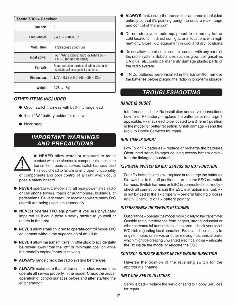
Tactic TR624 Receiver
Channels 6
Frequencies 2.403 – 2.480 GHz
Modulation FHSS spread spectrum
Input power Four “AA” alkaline, NiCd or NiMH cells(4.0 – 6.0V, not included)
Failsafe Programmable throttle, all other channelsmaintain last recognized positions
Dimensions 1.77 × 0.98 × 0.5" (45 × 25 × 13mm)
Weight 0.28 oz (8g)
OTHER ITEMS INCLUDED
● On/off switch harness with built-in charge lead
● 4 cell “AA” battery holder for receiver
● Neck strap
IMPORTANT WARNINGSAND PRECAUTIONS
● NEVER allow water or moisture to make contact with the electronic components inside the transmitter, receiver, servos, switch harness, etc.! This could lead to failure or improper functionality
of components and poor control of aircraft which could pose a safety hazard.
● NEVER operate R/C model aircraft near power lines, radio or cell phone towers, roads or automobiles, buildings, or pedestrians. Be very careful in locations where many R/C aircraft are being used simultaneously.
● NEVER operate R/C equipment if you are physically impaired as it could pose a safety hazard to yourself or others in the area.
● NEVER allow small children to operate/control model R/C equipment without the supervision of an adult.
● NEVER allow the transmitter’s throttle stick to accidentally be moved away from the “off” or minimum position while the model’s engine/motor is moving.
● ALWAYS range check the radio system before use.
● ALWAYS make sure that all transmitter stick movements operate all servos properly in the model. Check the proper operation of control surfaces before and after starting the engine/motor.
● ALWAYS make sure the transmitter antenna is unfolded entirely so that it’s pointing upright to ensure max. range and control of the aircraft.
● Do not store your radio equipment in extremely hot or cold locations, in direct sunlight, or in locations with high humidity. Store R/C equipment in cool and dry locations.
● Do not allow chemicals to come in contact with any parts of the radio system. Substances such as glow fuel, gasoline, CA glue, etc. could permanently damage plastic parts of the radio system.
● If NiCd batteries were installed in the transmitter, remove the batteries before placing the radio in long-term storage.
TROUBLESHOOTING
RANGE IS SHORT
Interference – check Rx installation and servo connections. Low Tx or Rx battery – replace the batteries or recharge if applicable. Rx may need to be located to a different position in the model for better reception. Crash damage – send the radio to Hobby Services for repair.
RUN TIME IS SHORT
Low Tx or Rx batteries – replace or recharge the batteries. Obstructed servo linkages causing excess battery drain – free the linkages / pushrods.
Tx POWER SWITCH ON BUT SERVOS DO NOT FUNCTION
Tx or Rx batteries are low – replace or recharge the batteries. Rx switch is in the off position – turn on the ESC or switch harness. Switch harness or ESC is connected incorrectly – check all connections and the ESC instruction manual. Rx is not binded to the Tx properly – perform binding process again. Check Tx or Rx battery polarity.
INTERFERENCE OR SERVOS GLITCHING
Out of range – operate the model more closely to the transmitter. Outside radio interference from pagers, strong industrial or other commercial transmitters in the area - check your local R/C club regarding local operation. Rx located too closely to engine, motor, or servos or other moving mechanical parts which might be creating unwanted electrical noise – relocate the Rx inside the model or relocate the ESC.
CONTROL SURFACE MOVES IN THE WRONG DIRECTION
Reverse the position of the reversing switch for the appropriate channel.
ONLY ONE SERVO GLITCHES
Servo is bad – replace the servo or send to Hobby Services for repair.
18
FAILSAFE NOT WORKING CORRECTLY
Receiver is not properly binded to the transmitter – bind the Rx to the Tx and re-try. Contact Hobby Services for further details.
WIRELESS TRAINING FUNCTION NOT BINDING
Check to see that another Tactic 2.4GHz system is not on in your area. The teacher’s and student’s transmitters were not powered in the proper sequence. Carefully follow the instructions on page 3 for proper binding and operation for training.
RECHARGEABLE BATTERIES WON’T ACCEPT CHARGE THROUGH THE TRANSMITTER
Check the charger for proper setup and operation. Make sure the charge plug is inserted fully into the charge jack. Make sure the transmitter’s power switch is in the OFF position. Make sure the cells are inserted inside the battery compartment in the proper direction.
FCC STATEMENT
This device complies with part 15 of the FCC rules. Operation is subject to the following two conditions.
(1) This device may not cause harmful interference.
(2) This device must accept any interference received, including interference that may cause undesired operation.
FCC RF Radiated Exposure Statement: The equipment complies with FCC RF radiation exposure limits set forth for an uncontrolled environment. This equipment should be installed and operated with a minimum distance of 20 centimeters between the radiator and your body.
Note: The manufacturer is not responsible for any radio or TV interference caused by unauthorized modifi cations to this equipment. Any changes or modifi cations not expressly approved by the party responsible for compliance could void the user’s authority to operate the equipment.
FCC ID: IYFTTX404B
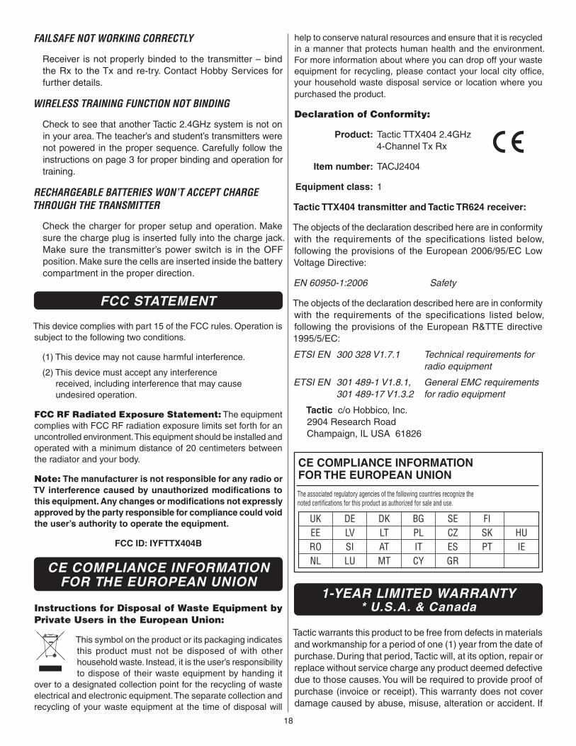
CE COMPLIANCE INFORMATIONFOR THE EUROPEAN UNION
Instructions for Disposal of Waste Equipment by Private Users in the European Union:
This symbol on the product or its packaging indicates this product must not be disposed of with other household waste. Instead, it is the user’s responsibility to dispose of their waste equipment by handing it
over to a designated collection point for the recycling of waste electrical and electronic equipment. The separate collection and recycling of your waste equipment at the time of disposal will
help to conserve natural resources and ensure that it is recycled in a manner that protects human health and the environment. For more information about where you can drop off your waste equipment for recycling, please contact your local city offi ce, your household waste disposal service or location where you purchased the product.
Declaration of Conformity:
Product: Tactic TTX404 2.4GHz 4-Channel Tx Rx
Item number: TACJ2404
Equipment class: 1
Tactic TTX404 transmitter and Tactic TR624 receiver:
The objects of the declaration described here are in conformity with the requirements of the specifi cations listed below, following the provisions of the European 2006/95/EC Low Voltage Directive:
EN 60950-1:2006 Safety
The objects of the declaration described here are in conformity with the requirements of the specifi cations listed below, following the provisions of the European R&TTE directive 1995/5/EC:
ETSI EN 300 328 V1.7.1 Technical requirements for radio equipment
ETSI EN 301 489-1 V1.8.1, General EMC requirements 301 489-17 V1.3.2 for radio equipment
Tactic c/o Hobbico, Inc.2904 Research RoadChampaign, IL USA 61826
CE COMPLIANCE INFORMATIONFOR THE EUROPEAN UNION
The associated regulatory agencies of the following countries recognize the noted certifications for this product as authorized for sale and use.
UK DE DK BG SE FIEE LV LT PL CZ SK HURO SI AT IT ES PT IENL LU MT CY GR
1-YEAR LIMITED WARRANTY* U.S.A. & Canada
Tactic warrants this product to be free from defects in materials and workmanship for a period of one (1) year from the date of purchase. During that period, Tactic will, at its option, repair or replace without service charge any product deemed defective due to those causes. You will be required to provide proof of purchase (invoice or receipt). This warranty does not cover damage caused by abuse, misuse, alteration or accident. If
19
there is damage stemming from these causes within the stated warranty period, Tactic will, at its option, repair or replace it for a service charge not greater than 50% of its then current retail list price. Be sure to include your daytime telephone number in case we need to contact you about your repair. This warranty gives you specifi c rights. You may have other rights, which vary from state to state.
For service on your Tactic product, send it post paid and insured to:
HOBBY SERVICES Ph: (217) 398-00073002 N. Apollo Dr., Suite 1 (9:00am – 5:00pm CST, M–F)Champaign, IL 61822
E-mail: [email protected]
● This product is suitable only for people of 14 years and older. This is not a toy!
● WARNING: CHOKING HAZARD - May contain small parts. Keep away from children under 3 years. Please retain packaging for future reference.
● No part of this manual may be reproduced in any form without prior permission.
● The contents of this manual are subject to change without prior notice.
● Tactic is not responsible for the use of this product.
This m
odel belongs to:
Nam
e
Address
City, S
tate, Zip
Phone N
umber
AM
A N
umber

™