Embed Size (px)
Citation preview
KNXProduct documentation
Issue:17.08.2015
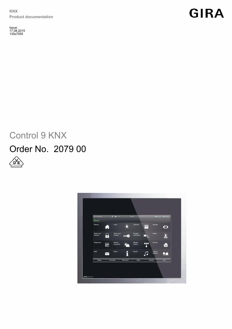
Control 9 KNXOrder No. 2079 00
135x7055
Order No. 2079 00
Table of ContentsProduct definition1 4.................................................................................................................
Product catalogue1.1 4...........................................................................................................Function1.2 4..........................................................................................................................Accessories1.3 6.....................................................................................................................
Installation, electrical connection and operation2 7..............................................................
Safety instructions2.1 7...........................................................................................................Device components2.2 8........................................................................................................Fitting and electrical connection2.3 11...................................................................................Commissioning2.4 14.............................................................................................................Operation2.5 15......................................................................................................................
Touch surface2.5.1 15........................................................................................................Operating elements on the device2.5.2 16.........................................................................Operation of the operating system2.5.3 18........................................................................
Technical data3 20....................................................................................................................
Software description4 21..........................................................................................................
Software specification4.1 21...................................................................................................Software "501411"4.2 22........................................................................................................
Scope of functions4.2.1 22.................................................................................................Notes on software4.2.2 24.................................................................................................Object table4.2.3 26...........................................................................................................Functional description4.2.4 43...........................................................................................
Available device resources4.2.4.1 43............................................................................Configuration software4.2.4.2 45...................................................................................
Introduction, installation and program start4.2.4.2.1 45............................................Structure and operation4.2.4.2.2 46..........................................................................Data comparison with ETS4.2.4.2.3 51.....................................................................Commissioning4.2.4.2.4 54.......................................................................................
Predefined display and operating functions4.2.4.3 57...................................................Display structure4.2.4.3.1 57.....................................................................................Operation concept and sensor evaluation4.2.4.3.2 64..............................................Operating and display function "Switching"4.2.4.3.3 67............................................Operating and display function "dimming Start/Stop"4.2.4.3.4 69.............................Operating and display function "Dimming brightness value"4.2.4.3.5 71..................Operating and display function "Venetian blind Step / Move / Step"4.2.4.3.6 73......Operating and display function "Venetian blind positioning"4.2.4.3.7 76..................Operating and display function "Rolling shutter Step / Move"4.2.4.3.8 79................Operating and display function "Rolling shutter positioning"4.2.4.3.9 82..................Operating and display function "Value transmitter"4.2.4.3.10 84................................Operating and display function "Value transmitter adjustmentfunction"
4.2.4.3.11 86...............
Operating and display function "Scene recall"4.2.4.3.12 89........................................Operating and display function "Operating mode switchover 4 x1-bit"
4.2.4.3.13 91...........
Operating and display function "Operating mode switchover KNX"4.2.4.3.14 94.......Operating and display function "Restraint"4.2.4.3.15 97.............................................
KNXProduct documentation
Page 2 of 227
Order No. 2079 00
Operating function "Internal open page"4.2.4.3.16 99.................................................Display function "Date / Time"4.2.4.3.17 100..............................................................Display function "KNX Time"4.2.4.3.18 101................................................................Display function "KNX Date"4.2.4.3.19 102.................................................................Display function "ASCII text display"4.2.4.3.20 103....................................................Display function "collective feedback"4.2.4.3.21 104..................................................
Settings4.2.4.4 106........................................................................................................General device parameters4.2.4.4.1 106..................................................................User and system settings4.2.4.4.2 113.....................................................................
Fault messages4.2.4.5 124............................................................................................Creating fault messages and the message window4.2.4.5.1 124.............................Acknowledgment and message list4.2.4.5.2 127......................................................
Scene function4.2.4.6 128.............................................................................................Definition and function4.2.4.6.1 128..........................................................................Creating and defining scene functions and scenes4.2.4.6.2 130..............................Configuration of scenes directly on the device4.2.4.6.3 132.....................................
Timer switch function4.2.4.7 135...................................................................................Definition and function4.2.4.7.1 135..........................................................................Astro and random function4.2.4.7.2 137...................................................................Creating and defining timer switch channels and switching times4.2.4.7.3 139.......Direct configuration of switching times4.2.4.7.4 142.................................................
Logical links4.2.4.8 144.................................................................................................Demultiplexer4.2.4.9 146...............................................................................................Timers4.2.4.10 148..........................................................................................................Limiting values4.2.4.11 149.............................................................................................e-mail4.2.4.12 152...........................................................................................................Datalogger4.2.4.13 154...................................................................................................
Datalogger recording4.2.4.13.1 154............................................................................Datalogger display4.2.4.13.2 157................................................................................
Presence simulation4.2.4.14 159.....................................................................................Configuring functions4.2.4.14.1 159............................................................................Using presence simulation4.2.4.14.2 160...................................................................
Signalling system4.2.4.15 165.........................................................................................Introduction and basic principles4.2.4.15.1 165..........................................................Detector4.2.4.15.2 171................................................................................................Arming4.2.4.15.3 174..................................................................................................Alarms4.2.4.15.4 177..................................................................................................Fault4.2.4.15.5 180......................................................................................................Event memory4.2.4.15.6 181......................................................................................Response to a device reset4.2.4.15.7 182..................................................................
Video messages4.2.4.16 183..........................................................................................Introduction4.2.4.16.1 183...........................................................................................Recording video messages4.2.4.16.2 184..................................................................Playing back video messages4.2.4.16.3 185..............................................................
Standby behaviour4.2.4.17 186.......................................................................................Parameters4.2.5 187..........................................................................................................
Appendix5 225...........................................................................................................................
Index5.1 225...........................................................................................................................
KNXProduct documentation
Page 3 of 227

Order No. 2079 00
1 Product definition1.1 Product catalogue
Product name: Control KNX 9
Use: Controller
Design: FM (flush-mounted)
Order No. 2079 00
1.2 FunctionThe device is used primarily to display statuses with a KNX installation and to control systemfunctions. The display elements are shown on a colour TFT monitor at a resolution of 800 x 480pixels (22.7 cm [9"], 16:9). The elements are controlled by touching the TFT monitor (touchscreen).The PC-based device has an Intel AtomTM processor without a fan and different interfaces forcommunication (KNX bus connection, Ethernet network connection) and for the connection ofoptional periphery (USB ports, SD slot for memory expansion and data exchange, audio andvideo connections for supplementary multimedia components). Furthermore, the device isequipped with a colour camera and microphone.Microsoft® Windows® XP Embedded serves as the operating system. Independent of thepreinstalled KNX application, the device can therefore also be used for other applications (e. g.door communication, Internet access using a preinstalled web browser, email function). Theinstallation and operation of KNX independent applications is performed as is standard in MSWindows, thereby allowing the device to be adapted flexibly to future applications.
The device displays all KNX functions clearly and concisely. By touching it is possible toexecute functions such as switching, dimming and Venetian blind control, to save and recalllight scenes as well as visualize and evaluate complex functions such as value transmitter, dateand limiting values.A clear and comprehensible menu navigation ensures fast access to the desired function. Theuse of predefined display pages available in the configuration software via a template librarymakes it possible to project design and commission the device in a uniform layout quickly and ina customer-friendly way.
A synchronisable real-time clock is available for setting up time switch functions and for loggingevents. Events or any other actions can be forwarded by a switching command usingpredefined e-mails. Furthermore, the device can be integrated into different light-scenes whosebrightness values can be saved permanently in the device memory for situation-dependentcontrol of a lighting system for KNX actuator groups.The device can be used to implement presence simulation and datalogger functionality. Thepresence simulation can, for example give those outside the impression that a house is lived in,even though the owners are away. The owners can record any simulations over periods of timeand play them back at any time. The datalogger provides the option of recording data, receivedfrom the KNX, in various formats, and displaying them on the unit. The data recorded by thedatalogger can also be forwarded by e-mail.If necessary, a signalling system can provide a security-orientated system to monitor doors andwindows. Up to two different signalling areas (internal / external) can be armed and monitoredfor break-ins and sabotage. Thus visual and acoustic alarming is possible using additional KNXcomponents (e.g. switching actuators) in conjunction with alarm encoders (flash light, internalsiren).
Up to 5 password levels allow controlled access to different functions. It is possible here toassign one of four password levels to the screen pages. The signalling system can be protectedagainst unauthorized access by its own password.Commissioning is possible by IP via the ethernet interface or via memory access (USB memorystick, SD card, network drive).
The device has a mains voltage terminal for power supply to the device electronics. The KNXfunction part (BCU) is functional as long as mains voltage and bus voltage are switched on. The
Page 4 of 227
Product definition

Order No. 2079 00
device can be switched off or switched to standby mode to enable energy-saving operation, asin the case of prolonged absence. Different KNX functions (e.g. signalling system, presencesimulation, timer...) remain active even when the device is in standby mode. If a device isswitched off, display and signalling functions are deactivated permanently.
Page 5 of 227
Product definition
Order No. 2079 00
1.3 AccessoriesDesign frame for Control 9 Order No. 2080 ..Flush-mounted housing/flush-mounted box forControl 9
Order No. 2082 00
Flush-mounted housing Order No. 0639 00Adapter frame Order No. 2081 00
Page 6 of 227
Product definition

Order No. 2079 00
2 Installation, electrical connection and operation2.1 Safety instructionsElectrical equipment may only be installed and fitted by electrically skilled persons. Theapplicable accident prevention regulations must be observed.Before working on the device or exchanging the connected loads, disconnect it from thepower supply (switch off the miniature circuit breaker), otherwise there is the risk of anelectric shock.Do not operate the screen with sharp or pointed objects. The touch-sensitive surfacecould be damaged.Do not use sharp objects for cleaning. Do not use sharp cleaning agents, acids ororganic solvents.Failure to observe the instructions may cause damage to the device and result in fire andother hazards.
Page 7 of 227
Installation, electrical connection and operation
Order No. 2079 00
2.2 Device components
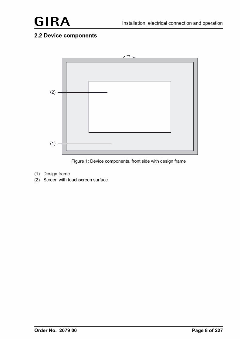
Figure 1: Device components, front side with design frame
(1) Design frame(2) Screen with touchscreen surface
Page 8 of 227
Installation, electrical connection and operation
Order No. 2079 00
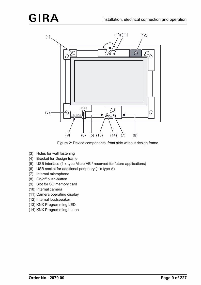
Figure 2: Device components, front side without design frame
(3) Holes for wall fastening(4) Bracket for Design frame(5) USB interface (1 x type Micro AB / reserved for future applications)(6) USB socket for additional periphery (1 x type A)(7) Internal microphone(8) On/off push-button(9) Slot for SD memory card(10) Internal camera(11) Camera operating display(12) Internal loudspeaker(13) KNX Programming LED(14) KNX Programming button
Page 9 of 227
Installation, electrical connection and operation
Order No. 2079 00
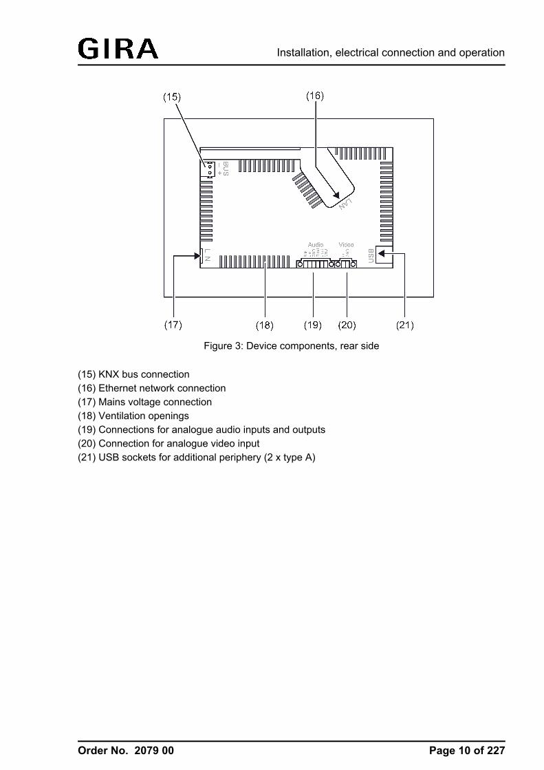
Figure 3: Device components, rear side
(15) KNX bus connection(16) Ethernet network connection(17) Mains voltage connection(18) Ventilation openings(19) Connections for analogue audio inputs and outputs(20) Connection for analogue video input(21) USB sockets for additional periphery (2 x type A)
Page 10 of 227
Installation, electrical connection and operation
Order No. 2079 00
2.3 Fitting and electrical connectionDANGER!Electrical shock when live parts are touched.Electrical shocks can be fatal.Before working on the device, disconnect the power supply and cover up liveparts in the working environment.
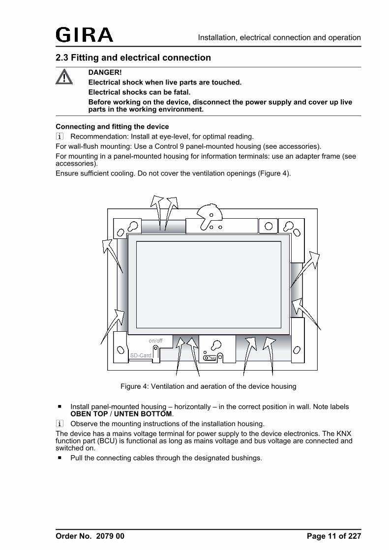
Connecting and fitting the devicei Recommendation: Install at eye-level, for optimal reading.For wall-flush mounting: Use a Control 9 panel-mounted housing (see accessories).For mounting in a panel-mounted housing for information terminals: use an adapter frame (seeaccessories).Ensure sufficient cooling. Do not cover the ventilation openings (Figure 4).
Figure 4: Ventilation and aeration of the device housing
o Install panel-mounted housing – horizontally – in the correct position in wall. Note labelsOBEN TOP / UNTEN BOTTOM.
i Observe the mounting instructions of the installation housing.The device has a mains voltage terminal for power supply to the device electronics. The KNXfunction part (BCU) is functional as long as mains voltage and bus voltage are connected andswitched on.o Pull the connecting cables through the designated bushings.
Page 11 of 227
Installation, electrical connection and operation
Order No. 2079 00
DANGER!Electrical shock when live parts are touched. The mains voltage and lowvoltage are located in a shared appliance box. If there is an error, otherconnected components may carry mains voltage.Electrical shocks can be fatal.Always secure the mains voltage with the enclosed tube. Run the cables so that low voltage wires are securely protected against mainsvoltage.
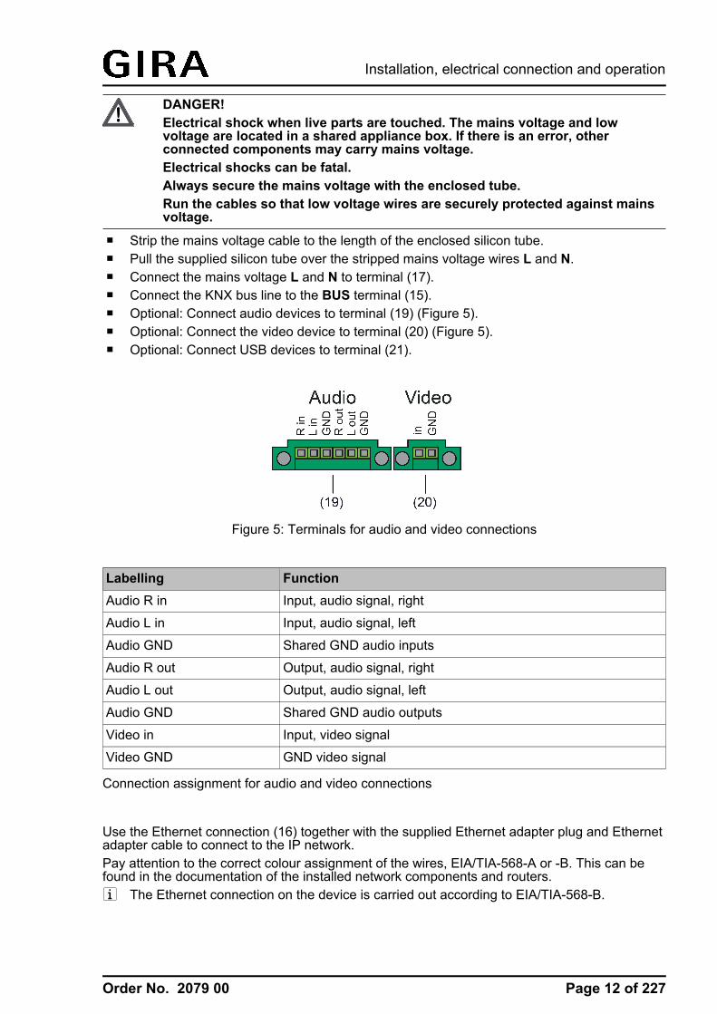
o Strip the mains voltage cable to the length of the enclosed silicon tube.o Pull the supplied silicon tube over the stripped mains voltage wires L and N.o Connect the mains voltage L and N to terminal (17).o Connect the KNX bus line to the BUS terminal (15).o Optional: Connect audio devices to terminal (19) (Figure 5).o Optional: Connect the video device to terminal (20) (Figure 5).o Optional: Connect USB devices to terminal (21).
Figure 5: Terminals for audio and video connections
Labelling FunctionAudio R in Input, audio signal, right
Audio L in Input, audio signal, left
Audio GND Shared GND audio inputs
Audio R out Output, audio signal, right
Audio L out Output, audio signal, left
Audio GND Shared GND audio outputs
Video in Input, video signal
Video GND GND video signal
Connection assignment for audio and video connections
Use the Ethernet connection (16) together with the supplied Ethernet adapter plug and Ethernetadapter cable to connect to the IP network.Pay attention to the correct colour assignment of the wires, EIA/TIA-568-A or -B. This can befound in the documentation of the installed network components and routers.i The Ethernet connection on the device is carried out according to EIA/TIA-568-B.
Page 12 of 227
Installation, electrical connection and operation

Order No. 2079 00
o Connect Ethernet installation cable to the Ethernet adapter plug. To do this, strip theEthernet wires, do not skin, and insert into the cover of the adapter plug. Shorten any wiresthat are jutting out and push the cover onto the adapter plug in the correct position(Figure 6).
o Connect the supplied Ethernet adapter cable to the terminal (16) and Ethernet adapterplug.
Figure 6: Fitting and connection of the Ethernet adapter plug
o Install device in panel-mounted housing. Use the screws supplied.o Remove protective film from the touchscreen surface (2).o Insert the Design frame in the correct direction into the designated brackets and push down
and to the left - down and to the right for vertical mounting - to fix it.
Page 13 of 227
Installation, electrical connection and operation
Order No. 2079 00
2.4 CommissioningCommissioningAfter installation of the device and connection of the KNX bus line, mains supply, Ethernetcable, and, if necessary, the optional periphery, the device can be put into operation. Thecommissioning is basically confined to programming of the physical address with the ETS andthe loading of the configuration data by the configuration software.
Programming the physical addressThe physical address is programmed using a KNX data interface in the ETS programming.Programming button (12) and LED (13) must be accessible.In addition, the ETS project database must be imported and an appropriate device inserted inthe project and a physical address assigned.o Switch on the device.
The device switches on the display and starts the booting process. After the operatingsystem has been loaded, the device starts the KNX application and first displays the startscreen. After a short waiting time, the project design last programmed in the device isdisplayed.
o Press the programming button (12).The programming LED (13) is illuminated.
o Program the physical address with the help of the ETS.The programming LED goes out if programming has been successful.
o Note the physical address on the device.
Programming the configuration dataAfter the physical address has been programmed, the configuration data must be programmedinto the device. The device is configured with the aid of the separate configuration software.Commissioning is possible by IP via the ethernet interface or via memory access (USB memorystick, SD card).i The ETS programming function (IP, USB or RS232 data interface) cannot be used for
programming the configuration data. If necessary, remove the decorative frame installed during mounting from the front of the device.o Switch on the device.
The device switches on the display and starts the booting process. After the operatingsystem has been loaded, the device starts the KNX application and first displays the startscreen. After a short waiting time, the configuration last programmed in the device isdisplayed.
o Open the configuration software.o The device is configured and parameterized with the aid of the configuration software.o When the configuration has been completed, carry out the programming operation (see
page 54).The progress of the programming operating is shown in the display of the device. When theprogramming operation has been completed, the device is initialised automatically. TheStart screen is displayed during initialisation.
o This completes the commissioning process.
Page 14 of 227
Installation, electrical connection and operation
Order No. 2079 00
2.5 Operation2.5.1 Touch surface
Sensoric touchscreen surfaceThe monitor possesses a sensoric surface, also know as a touch screen. The device isoperated by touching the monitor surface with your finger or with special touch screen pens (notcontained in the scope of supply).i Do not use sharp objects for operation. The surface may be damaged and thus operation
impeded.
Cleaning the touchscreenThe touchscreen requires regular cleaning in order to guarantee the optimum touch sensitivity.Keep the screen free of foreign bodies and dust. o Set application to "Cleaning function".o Clean the touchscreen carefully using a soft, lint-free cloth. If needed, moisten the cleaning
cloth slightly. i Do not use sharp cleaning agents, acids or organic solvents.i Keep moisture from penetrating into the device. Do not spray the cleaning agent directly
onto the screen surface.i Do not use sharp objects for cleaning.
Page 15 of 227
Installation, electrical connection and operation

Order No. 2079 00
2.5.2 Operating elements on the device
Removing the Design frameCertain operating elements are only accessible when the Design frame (1) has been removed(Figure 1).o Hold the bottom of the Design frame with both hands.o Carefully push the Design frame upwards to the right.o When the Design frame is loose in the bracket, pull it carefully away from the wall.
Mounting the Design frameo Insert the Design frame into the brackets (4) in the right position (Figure 2).o Carefully push the Design frame downwards until it engages.
Switching a device on or offThe device can be switched off to enable energy-saving operation, as in the case of prolongedabsence for instance. When switching off, the operating system is shut down. The display andsignalling functions of the device are then deactivated permanently.The On/off push-button (8) can be reached once the Design frame (1) has been removed.o Switching on: Press the push-button (8).
The device switches on after about 2 seconds.The operating system and KNX application (Autostart) are started.
o Terminate KNX application: Press push-button (8) 1 x briefly.The KNX application is terminated. The device changes to the Windows® operating systemand displays the desktop.
o Switch off: Press the push-button (8) again 1 x briefly.- or -
o Press the Windows® "Start" button and select the "Shut Down" command in the Start menu.In the subsequent list box, select "Shut Down" again and press the "OK" button.The operating system shuts down the device.The device switches off.
i The start menu of the operating system is available via the Windows® taskbar. The taskbaris normally in the background and is therefore not visible. The taskbar can be accessed byconnecting a USB keyboard. The KNX application can then also be terminated correctly,for example, via the "ALT + F4" shortcut key.
i Alternatively, the device can be shut down into standby mode via the Windows® start menu.Operating the touchscreen then immediately reactivates the device. Unlike switching off,the device in standby mode can also be reactivated by the KNX function part when anevent occurs. The device is then able to perform display and signalling functions event-driven.The energy saving is approximately the same if the device is switched off or in standbymode. The standby mode is recommended.
i The function of the pushbutton control (8) can be changed in the Windows® operatingsystem within the energy management settings (System control -> Energy options ->Power switch processes) and adjusted to the requirements of the user.
Page 16 of 227
Installation, electrical connection and operation
Order No. 2079 00
i Different KNX functions (e.g. signalling system, presence simulation, timer...) remain activeeven when the device is switched off or in standby mode. The KNX function part (BCU) isfunctional in these cases provided that the mains voltage and bus voltage is availableinterruption-free. A device in standby mode can also be reactivated by the KNX functionpart. This does not work if a device is switched off. Display and signalling functions arethen deactivated permanently.
Carrying out a resetIf the device can no longer be operated, e.g. after a program error, it can be reset and switchedoff. A complete reset is executed here i.e. all data not permanently saved is lost.o Press the push-button (8) for approx. 5 seconds.
The device switches off after about 5 seconds. The operating system is not safely shutdown in the process.
i Different KNX functions (e.g. signalling system, presence simulation...) remain active evenwhen the device is switched off. The KNX function part (BCU) is functional even when thedevice is switched off, provided that the mains voltage and bus voltage is availableinterruption-free.
Page 17 of 227
Installation, electrical connection and operation
Order No. 2079 00
2.5.3 Operation of the operating system
Operating system and KNX applicationThe operating system of the device is based on Microsoft® Windows® XP Professional in amemory-optimised version. All the components required for the device function are preinstalled.Additional drivers or programs, e.g. Gira software package QuadClient, can be installed in theWindows environment at any time later.The KNX device application starts automatically after switching on the device (booting process).The KNX application that should always be in the foreground in normal operation must beminimized or even terminated in order to subsequently install other programs or drivers. It ispossible to terminate the KNX application by briefly pressing the ON/OFF button (8). As a result,the device changes to the Windows® operating system and displays the desktop.The KNX application can be minimized via the Windows taskbar. The Windows taskbar isnormally in the background and is therefore not visible. The taskbar can be accessed byconnecting a USB keyboard.i When installing additional software or saving data, always observe the system resources
available!
Graphic Windows® user interfaceOnce the KNX application has been minimized or terminated, the device provides a graphicWindows® user interface (Figure 7) with desktop (22) and taskbar (26) in activated state. Theuser can – as well as with other Windows PCs – modify the appearance accordingly.i The Windows user interface and all other system programs are available with connected
USB keyboard. A USB mouse can be connected to the device for easy operation ifrequired.
Operation is carried out using a mouse pointer (23), which follows the operations of thetouchscreen or the connected USB mouse. Brief touches of the screen are interpreted asactuation of the mouse buttons. The function of the right mouse button in touch operation canbe activated using the mouse button switching (29). Text can be input using the Windows on-screen keyboard (25).
Figure 7: Windows screen elements
(22) Windows desktop(23) Mouse pointer(24) Start menu(25) On-screen keyboard(26) Taskbar(27) System programs(28) Preinstalled programs for the touchscreen calibration and for hiding the mouse pointer(29) Mouse button switching(30) Microsoft Windows terms and conditions
System programs are preinstalled in the info area of the taskbar (27), e.g. for the audio controland for network settings.
Page 18 of 227
Installation, electrical connection and operation

Order No. 2079 00
i The arrangements of the icons on the desktop or in the taskbar may vary from therepresentation shown.
File-based write filterThe device contains an SSD drive with no moving parts as a mass storage facility. To preventaccidental changes to the configuration, the drive is protected by a file-based write filter - File-Based Write Filter (FBWF). Write operations to the protected are a diverted to a virtual drive inthe RAM. Changes to this data are shown in the directory but are only available until the deviceis restarted. The previous data is restored is the device is switched-off or there is a powerfailure.Changes to the "My Documents" directory are excluded from write-protection and are alwaysapplied.
The write filter must be switched off, ...- When directories are created, which are to remain intact after a restart,- When programs are installed.The system must be restarted, ...- When the write filter is switched on or off,- When the size of the virtual drive is changed,- When memory compression is switched on or offThe user can change the settings for the file-based write filter.
Installing programsBefore installing additional programs, take the system requirements of the programs intoaccount.o Deactivate write filters: Select the program for the write protection settings using the mouse
pointer(available on the desktop or in the taskbar).o Select the menu item "Write protection".
The window for the write filter settings opens.o Deactivate write protection.o Press the "Apply" button. o Press the "Close" button.o Shut down the device and restart it.o Install the program, e.g. from a USB stick.o Activate write filters: Reselect the program for the write protection settings using the mouse
pointer.o Select the menu item "Write protection".o Activate write protection.o Press the "Apply" button. o Press the "Close" button.o Shut down the device and restart it.
Page 19 of 227
Installation, electrical connection and operation
Order No. 2079 00
3 Technical data
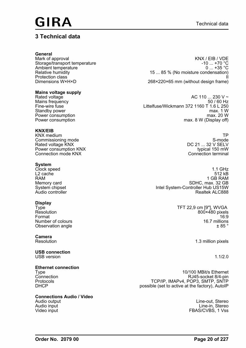
GeneralMark of approval KNX / EIB / VDEStorage/transport temperature -10 ... +70 °CAmbient temperature 0 ... +35 °CRelative humidity 15 ... 85 % (No moisture condensation)Protection class IIDimensions W×H×D 268×220×65 mm (without design frame)
Mains voltage supplyRated voltage AC 110 ... 230 V ~Mains frequency 50 / 60 HzFine-wire fuse Littelfuse/Wickmann 372 1160 T 1.6 L 250Standby power max. 1 WPower consumption max. 20 WPower consumption max. 8 W (Display off)
KNX/EIBKNX medium TPCommissioning mode S-modeRated voltage KNX DC 21 ... 32 V SELVPower consumption KNX typical 150 mWConnection mode KNX Connection terminal
SystemClock speed 1.1 GHzL2 cache 512 kBRAM 1 GB RAMMemory card SDHC, max. 32 GBSystem chipset Intel System-Controller Hub US15WAudio controller Realtek ALC888
DisplayType TFT 22,9 cm [9"], WVGA Resolution 800×480 pixelsFormat 16:9Number of colours 16.7 millionsObservation angle ± 85 °
CameraResolution 1.3 million pixels
USB connectionUSB version 1.1/2.0
Ethernet connectionType 10/100 MBit/s EthernetConnection RJ45-socket 8/4-pinProtocols TCP/IP, IMAPv4, POP3, SMTP, SNTPDHCP possible (set to active at the factory), AutoIP
Connections Audio / VideoAudio output Line-out, StereoAudio input Line-in, StereoVideo input FBAS/CVBS, 1 Vss
Page 20 of 227
Technical data
Order No. 2079 00
4 Software description4.1 Software specificationETS search paths: / Control KNX 9BAU used: TPUART + µCKNX type class: 3g device with cert. PhL + stack + µCConfiguration: S-mode with plug-in
Application program:
No. Short description Name Version from maskversion
1 KNX display and operating panel withcoloured touch display.
Control 9 KNX501411
1.1 701
Page 21 of 227
Software specification
Order No. 2079 00
4.2 Software "501411"4.2.1 Scope of functions
Scope of functions- The device is used to control building functions and to display building statuses of various
features of a KNX installation.
- Uniform screen layout by the use of predefined display pages available in the configurationsoftware via a template library. This ensures fast and customer-friendly project design andcommissioning of the device.
- The display elements can be configured to the functions switching, dimming, blinds, valuedisplay with various variables, light scene control, date, time, text display, dataloggerdisplay, restraint, operating mode switch of a heating/cooling system, collective feedback orload type of a dimmer actuator.
- The device possesses an Ethernet interface. Various embedded IP protocols allow event-driven email messages to be sent by the KNX application. It is also possible to use theWindows network functions independent of the KNX application.
- Up to 4 password levels allow controlled access to different display pages and functions. Itis possible here to assign one password level each to the screen pages. The signallingsystem and commissioning function can be protected against unauthorized access by itsown password.
- A weekly timer with up to 64 channels and a total of 128 switching times is available. Theindividual channels can be used for different functions (switching, values, light scenes,operating mode switching). A random and an astro function can be activated optionally oneach timer switch channel. The switching times are programmed in the configurationsoftware or directly on the device after commissioning.
- Up 24 light scenes with a total of 32 actuator groups can be created. The light scenes areset directly on the device after commissioning.
- There are up to 80 logical links available, each with up to 8 inputs, up to 12 multiplexerseach with up to three channels and 40 timers with ON delay and OFF delay and a filterfunction.
- Up to 50 different fault messages can be used. Of these fault messages, up to 20 can beactive simultaneously. Activation, acknowledgement and deactivation of fault messagescan be logged in a message list.
- A presence simulation allows the recording or playing back of any simulations over specificperiods of time.
- A datalogger provides the option of recording data received from the KNX in variousformats, and displaying it on the device. The data recorded by the datalogger can also beforwarded by e-mail.
Page 22 of 227
Software "501411"Scope of functions
Order No. 2079 00
- If necessary, a signalling system can provide a security-orientated system to monitor doorsand windows. Up to two different signalling areas (internal / external) can be armed andmonitored for break-ins and sabotage. Thus visual and acoustic alarming is possible usingadditional KNX components (e.g. switching actuators) in conjunction with alarm encoders(flash light, internal siren).
- The project design takes place with configuration software independent of the ETS.Commissioning is possible via the Ethernet interface or via memory access (USB memorystick, SD card, network drive).
Page 23 of 227
Software "501411"Scope of functions

Order No. 2079 00
4.2.2 Notes on software
Project design and commissioningThe ETS application program described in this documentation with the number "...5014 1.1" isused in conjunction with the configuration software to configure and commission the device withthe Gira order no. 2079 00 (Control 9 KNX).The above-mentioned application cannot be programmed in other devices (e.g. InfoTerminalTouch with Ethernet interface - 2072 xx / InfoTerminal Touch - 2071 xx). There are differentapplication programs available for this purpose.
Operating system and KNX applicationThe operating system of the device is based on Microsoft® Windows® XP Professional in amemory-optimised version. All the components required for the device function are preinstalled.Additional drivers or programs, e.g. Gira software package QuadClient, can be installed in theWindows environment at any time later.The KNX device application starts automatically after switching on the device (booting process).The KNX application that should always be in the foreground in normal operation must beminimized or even terminated in order to subsequently install other programs or drivers. It ispossible to terminate the KNX application by briefly pressing the ON/OFF button (8). As a result,the device changes to the Windows® operating system and displays the desktop.The KNX application can be minimized via the Windows taskbar. The Windows taskbar isnormally in the background and is therefore not visible. The taskbar can be accessed byconnecting a USB keyboard.i When installing additional software or saving data, always observe the system resources
available!
File-based write filterThe device contains an SSD drive with no moving parts as a mass storage facility. To preventaccidental changes to the configuration, the drive is protected by a file-based write filter - File-Based Write Filter (FBWF). Write operations to the protected are a diverted to a virtual drive inthe RAM. Changes to this data are shown in the directory but are only available until the deviceis restarted. The previous data is restored is the device is switched-off or there is a powerfailure.Changes to the "My Documents" directory are excluded from write-protection and are alwaysapplied.
The write filter must be switched off, ...- When directories are created, which are to remain intact after a restart,- When programs are installed.The system must be restarted, ...- When the write filter is switched on or off,- When the size of the virtual drive is changed,- When memory compression is switched on or offThe user can change the settings for the file-based write filter.
Installing programsBefore installing additional programs, take the system requirements of the programs intoaccount.o Deactivate write filters: Select the program for the write protection settings using the mouse
pointer(available on the desktop or in the taskbar).o Select the menu item "Write protection".
Page 24 of 227
Software "501411"Notes on software
Order No. 2079 00
The window for the write filter settings opens.o Deactivate write protection.o Press the "Apply" button. o Press the "Close" button.o Shut down the device and restart it.o Install the program, e.g. from a USB stick.o Activate write filters: Reselect the program for the write protection settings using the mouse
pointer.o Select the menu item "Write protection".o Activate write protection.o Press the "Apply" button. o Press the "Close" button.o Shut down the device and restart it.
Page 25 of 227
Software "501411"Notes on software
Order No. 2079 00
4.2.3 Object table
Number of communication objects: max. 2,000Generated dynamically
Number of addresses (max): 3,000
Number of assignments (max): 3,000
Dynamic table management no
i The communication objects are generated dynamically by the configuration softwareaccording to requirements. The available object resources of the device define the numberof configurable objects. The resources can be reduced depending on the configuredfunctions and data formats thus used. The device has the following object resources in theunconfigured state...1-bit (Switching): 8002-bit (Restraint): 504-bit (Relative dimming): 3001-byte (Value): 3002-byte (Value): 2003-byte (Date, Time): 504-byte (Value): 20014-byte (Text): 100
i Within the ETS (Project view), all configured objects are each displayed independently withallocated group addresses after a data comparison (see page 51) depending on the dataformat. Dynamic objects of the visualisation are displayed without identification of thefunction affiliation, i.e. objects are not identified with the display texts of the functions (e.g.the object name "switching object" or "dimming object"). For predefined functions (e.g.signalling system or presence simulation) the objects are labelled by function affiliation(e.g. object name "ready to arm internal [Signalling system input]" or "Playback Start/Stop[presence simulation]").Group addresses may only be linked with communication objects in the configurationsoftware! The data management in the ETS project is only for maintaining the addresstable (specification of the data formats) and for generating filter tables for backbone/linecouplers.
i The communication objects for display and operating functions of the visualisation aredependent on the corresponding configured KNX function. This documentation describesthese objects in detail and function specifically in the chapters of the predefined display andoperating functions (see page 57).
Object for the status line
Function: Status lineObject
h
Function2-byte object
NameInteriortemperature
Type2 byte
DPT9.001
FlagC, W
Description 2-byte object for receiving a current room indoor temperature. The receivedvalue is displayed in the status line.Displayable value range: -99 to +99.
Page 26 of 227
Software "501411"Object table
Order No. 2079 00
Function: Status lineObject
h
Function2-byte object
NameOutdoortemperature
Type2 byte
DPT9.001
FlagC, W
Description 2-byte object for receiving a current outdoor temperature. The received valueis displayed in the status line.Displayable value range: -99 to +99.
Object for display illumination
Function: Display illuminationObject
h
Function1-bit object
NameDisplayillumination
Type1-bit
DPT1.001
FlagC, W
Description 1 bit object, using which the display background lighting can be switched offand on. Telegram polarity configurable.After a time interval set in the configuration software has elapsed, the lightingautomatically switches back to the basic level of brightness.
Objects of the system clock
Function: TimeObject
h
Function3-byte object
NameTime object
Type3 byte
DPT10.001
FlagC, W, T
Description 3 byte object with which the device can send the internal time to the buscyclically or on request.
Function: DateObject
h
Function3-byte object
NameDate object
Type3 byte
DPT11.001
FlagC, W, T
Description 3 byte object with which the device can send the internal date to the buscyclically or on request.
Page 27 of 227
Software "501411"Object table
Order No. 2079 00
Function: Date / time request by external deviceObject
h
Function1-bit object
NameRequest date /time by externaldevice
Type1-bit
DPT1.001
FlagC, W
Description 1 bit object, using which the device can receive a request telegram fromanother KNX subscriber (depending on parameters). The device responds toan external poll by transmitting the data and/or time telegram via the "Dateobject" and "Time object" objects. You can use the configuration software toconfigure which of these telegrams is sent. The telegram polarity of theexternal poll telegram can be configured.
Function: Master clock dateObject
h
Function3-byte object
NameMaster date
Type3 byte
DPT11.001
FlagC, W, T
Description 3 byte object, with which the device can receive the current date from a KNXmaster clock for synchronisation (parameter-dependent).
Function: Master clock timeObject
h
Function3-byte object
NameMaster time
Type3 byte
DPT10.001
FlagC, W, T
Description 3 byte object, with which the device can receive the current time from a KNXmaster clock for synchronisation (parameter-dependent).
Function: Master clock date / time requestObject
h
Function1-bit object
NameRequest date /time
Type1-bit
DPT1.001
FlagC, T
Description 1 bit object, using which a request telegram for the data and time on the KNXcan be transmitted (depending on parameters). In this way, the device can pollthe date and current time from another bus subscriber, e.g. Master clock. Theresponse of the master is then expected via the objects "MasterDate" and"MasterTime".The request is made after a restart and then every night at 4.00 am. Thetelegram polarity can be configured.
Page 28 of 227
Software "501411"Object table
Order No. 2079 00
Objects for external open pages
Function: Open pageObject
h
Function1-bit object
NameOpen page [openpage external]
Type1-bit
DPT1.001
FlagC, W
Description 1-bit object with which display pages can be opened directly. An opened pageimmediately appears on the device display. Each display page has its ownobject that can be enabled in the configuration software if required.
Object for disabling function of the device
Function: Device disabling functionObject
h
Function1-bit object
NameDisabling object ofdevices [disabledevice]
Type1-bit
DPT1.001
FlagC, W
Description 1-bit object for activation and deactivation of the device disabling function(polarity configurable). A disabled device displays a disabling logo on thescreen (optional) and can execute a special disabling function if required. Allother display and operating functions are then out of operation.
Object for the digital picture frame
Function: Digital picture frame disabling functionObject
h
Function1-bit object
NameDisable object[digital pictureframe]
Type1-bit
DPT1.001
FlagC, W
Description 1-bit object for disabling the digital picture frame (polarity configurable). This isadvisable, for instance, if the image display should not be started orinterrupted at certain times of the day or night because they have a disturbingeffect on the environment. An image display that has already started can becancelled by the disabling object. A restart of the image display is onlypossible when the disabling object is deactivated.
Page 29 of 227
Software "501411"Object table
Order No. 2079 00
Objects for the datalogger
Function: DataloggerObject
h
Function1/2/4-byte object
NameRecording object[Dataloggerchannel]
Type1 byte2 byte4 byte
DPT5.001...5.0045.0106.0107.0018.0019.001...9.02112.00113.00114.000...14.079
FlagC, W
Description Object with settable type, whose value is recorded by the device at settabletimes and which can be displayed in a display element as a dataloggerchannel as a diagram on the screen.
Objects for the logic gate
Function: Logic gate inputsObject
h
Function1-bit object
NameInput object [logicgate]
Type1-bit
DPT1.001
FlagC, W
Description 1 bit objects, which can be logically linked to each other. Each input object of alogic gate can be processed either normally or inverted.
Function: Logic gatesObject
h
Function1-bit object
NameStart object [logicgates]
Type1-bit
DPT1.001
FlagC, W, T
Description 1 bit object, which outputs the result of the logical link. The type of link (AND,OR, EXCLUSIVE OR, AND with return), the behaviour (normal or inverted)and the transmit criterion (transmit on any input event or send on changing theoutput) can be set.
Function: Logic gatesObject
h
Function1-bit object
NameDisabling object[Logic gate]
Type1-bit
DPT1.001
FlagC, W
Description 1-bit object for disabling or enabling the gate output (polarity configurable).
Page 30 of 227
Software "501411"Object table
Order No. 2079 00
Objects for the demultiplexer
Function: DemultiplexerObject
h
Function1/4-bit object,1/2/4-byte object
NameInput object[Demultiplexer]
Type1-bit4-bit1 byte2 byte4 byte
DPT1.001…1.0083.0075.001...5.0045.0106.0107.0018.0019.001...9.02112.00113.00114.000...14.079
FlagC, W
Description Object with adjustable type, who value is forwarded to one of two or fouroutput objects according to one or control objects.
Function: DemultiplexerObject
h
Function1-bit object
NameControl object 1/2[Demultiplexer]
Type1-bit
DPT1.001
FlagC, W
Description 1 bit object which specifies to which output object the value of thecorresponding input object is forwarded.Two control objects may be visible, depending on the configured function (1 to2 demultiplexers or 1 to 4 demultiplexers).
Function: DemultiplexerObject
h
Function1/4-bit object,1/2/4-byte object
NameStart object 1/2/3/4[Demultiplexer]
Type1-bit4-bit1 byte2 byte4 byte
DPT1.001…1.0083.0075.001...5.0045.0106.0107.0018.0019.001...9.02112.00113.00114.000...14.079
FlagC, W, T
Description One of two or one of four output objects receiving the value of the input object.
Page 31 of 227
Software "501411"Object table
Order No. 2079 00
Function: DemultiplexerObject
h
Function1-bit object
NameDisabling object[Demultiplexer]
Type1-bit
DPT1.001
FlagC, W
Description 1-bit object which specifies whether the value of the active output object of thedemultiplexer can be transmitted (polarity configurable).
Objects for the timers
Function: TimerObject
h
Function1-bit object
NameInput object[Timer]
Type1-bit
DPT1.001
FlagC, W
Description 1 bit object, whose value is forwarded to the output object of the timer,depending on the value of the appropriate disabling object, the set filterfunction and the defined delays.
Function: TimerObject
h
Function1-bit object
NameStart object [Timer]
Type1-bit
DPT1.001
FlagC, W, T
Description 1 bit object which forwards the logical switching state of the timer output.
Function: TimerObject
h
FunctionTimer
NameDisabling object[timer]
Type1-bit
DPT1.001
FlagC, W
Description 1-bit object which specifies whether the value of the corresponding inputobject is forwarded to the output object (polarity configurable).
Page 32 of 227
Software "501411"Object table
Order No. 2079 00
Objects for the limiting values
Function: Limiting valueObject
h
Function1/2/4-byte object
NameValue object[limiting valueinput]
Type1 byte2 byte4 byte
DPT5.001...5.0045.0106.0107.0018.0019.001...9.02112.00113.00114.000...14.079
FlagC, W
Description Object with adjustable type for transferring the input value to a limiting valuemodule. The value received via this object is compared continuously with theconfigured limiting values. The limiting value modules have one value inputobject each.
Function: Limiting valueObject
h
Function1-bit object
NameUpper limitingvalue [limitingvalue output]
Type1-bit
DPT1.001
FlagC, W, T
Description 1-bit object for monitoring the upper limiting value. If the upper limiting value isexceeded or fallen short of (minus hysteresis), the configured switchingtelegram is transmitted via this object.
Function: Limiting valueObject
h
Function1-bit object
NameLower limitingvalue [limitingvalue output]
Type1-bit
DPT1.001
FlagC, W, T
Description 1-bit object for monitoring the lower limiting value. If the lower limiting value isfallen short of or exceeded (plus hysteresis), the configured switchingtelegram is transmitted via this object.
Page 33 of 227
Software "501411"Object table
Order No. 2079 00
Objects for status timer
Function: Timer switching channelObject
h
Function1-bit object
NameSwitching
Type1-bit
DPT1.001
FlagC, W, T
Description 1-bit object for outputting switching telegrams of a switching channel of thetype "Switching".
Function: Timer switching channelObject
h
Function1-bit object
NameComfort object[timer]
Type1-bit
DPT1.001
FlagC, W, T
Description 1-bit object for outputting telegrams for switching over to the "Comfort"operating mode (control of a room temperature controller) of a switchingchannel of the type "operating mode switch 4 x 1-bit".
Function: Timer switching channelObject
h
Function1-bit object
NameStandby object[timer]
Type1-bit
DPT1.001
FlagC, W, T
Description 1-bit object for outputting telegrams for switching over to the "Standby"operating mode (control of a room temperature controller) of a switchingchannel of the type "operating mode switch 4 x 1-bit".
Function: Timer switching channelObject
h
Function1-bit object
NameNight reductionobject [Timer]
Type1-bit
DPT1.001
FlagC, W, T
Description 1-bit object for outputting telegrams for switching over to the "Night" operatingmode (control of a room temperature controller) of a switching channel of thetype "operating mode switch 4 x 1-bit".
Function: Timer switching channelObject
h
Function1-bit object
NameFrost/heatprotection object[Timer]
Type1-bit
DPT1.001
FlagC, W, T
Description 1-bit object for outputting telegrams for switching over to the "Frost/heatprotection" operating mode (control of a room temperature controller) of aswitching channel of the type "operating mode switch 4 x 1-bit".
Page 34 of 227
Software "501411"Object table
Order No. 2079 00
Function: Timer switching channelObject
h
Function1-byte object
NameOperating mode[Timer]
Type1 byte
DPT20.102
FlagC, W, T
Description 1-byte object for outputting telegrams for KNX operating mode switchover(control of a room temperature controller) of a switching channel of the type"operating mode switch KNX".
Function: Timer switching channelObject
h
Function1/2/4-byte object
NameValue object[Timer]
Type1 byte2 byte4 byte
DPT5.001...5.0045.0106.0107.0018.0019.001...9.02112.00113.00114.000...14.079
FlagC, W, T
Description Object with adjustable type for outputting value telegrams of a switchingchannel of the type "Value".
Objects for the event mails
Function: Event e-mailObject
h
Function1-bit object
NameSend e-mail [E-Mail]
Type1-bit
DPT1.001
FlagC, W
Description 1-bit object for transmission of an event email. If a telegram with theconfigured polarity is received via this object, the device transmits apreconfigured event email. A separate object is available for each event email.
Page 35 of 227
Software "501411"Object table
Order No. 2079 00
Objects for the signalling system
Function: Signalling systemObject
h
Function1-bit object
NameDetector[signalling systeminput]
Type1-bit
DPT1.001
FlagC, W, T
Description 1 bit object as detector input. There is exactly one detector object for eachcreated detector input for the internal and external skin security areas. Thegroup address of exactly one KNX detector is linked to this object. Thetelegram polarity of the detector telegram can be configured.The signalling system cyclically tests the function of a KNX detector, by thesystem transmitting a value read telegram to the bus via the detector object.The KNX detector (e.g. the channel of a button interface of a binary input)must answer the read telegram of the signalling system with a value answertelegram. For this, the "Read" flag must be set on the communication object ofthe KNX detector.
Function: Signalling systemObject
h
Function1-bit object
NameInternally armed,external skinmonitoring[signalling systeminput]
Type1-bit
DPT1.001
FlagC, W
Description 1 bit object to arm and unarm the external skin monitoring (internally armed).0 = Unarm / 1 = Arm
Function: Signalling systemObject
h
Function1-bit object
NameExternally armed,internal andexternal skinmonitoring[signalling systeminput]
Type1-bit
DPT1.001
FlagC, W
Description 1 bit object to arm and unarm the internal and external skin monitoring(externally armed).0 = Unarm / 1 = Arm
Function: Signalling systemObject
h
Function1-bit object
NameSabotage[signalling systeminput]
Type1-bit
DPT1.001
FlagC, W
Description 1 bit object as a sabotage of the signalling system. The sabotage detector canbe connected to this object.0 = No sabotage, detector inactive / 1 = Sabotage, detector active
Page 36 of 227
Software "501411"Object table
Order No. 2079 00
Function: Signalling systemObject
h
Function1-bit object
NameReady to arm,internal [signallingsystem output]
Type1-bit
DPT1.001
FlagC, T
Description 1 bit object to signal that the signalling system is internally ready to arm. Thesystem is only internally ready to arm when none of the detectors allocated tothe external skin is active and there is no fault.0 = Not ready to arm / 1 = Ready to arm
Function: Signalling systemObject
h
Function1-bit object
NameReady to arm,external [signallingsystem output]
Type1-bit
DPT1.001
FlagC, T
Description 1 bit object to signal that the signalling system is externally ready to arm. Thesystem is only externally ready to arm when none of the detectors allocated tothe internal skin and the external skin is active and there is no fault.0 = Not ready to arm / 1 = Ready to arm
Function: Signalling systemObject
h
Function1-bit object
NameArming message,internal [signallingsystem output]
Type1-bit
DPT1.001
FlagC, T
Description 1 bit object for static signalling that the signalling system has successfullyarmed internally, i.e. the external skin monitoring is active.0 = External skin monitoring not armed / 1 = External skin monitoring armed
Function: Signalling systemObject
h
Function1-bit object
NameArming message,external [signallingsystem output]
Type1-bit
DPT1.001
FlagC, T
Description 1 bit object for static signalling that the signalling system has successfullyarmed externally, i.e. the internal ad external skin monitoring is active.0 = Internal/external skin monitoring not armed / 1 = Internal/external skinmonitoring armed
Function: Signalling systemObject
h
Function1-bit object
NameAlarm [signallingsystem output]
Type1-bit
DPT1.001
FlagC, T
Description 1 bit object to signal a break-in or sabotage alarm.0 = No alarm / 1 = Alarm
Page 37 of 227
Software "501411"Object table
Order No. 2079 00
Function: Signalling systemObject
h
Function1-bit object
NameFault [signallingsystem output]
Type1-bit
DPT1.001
FlagC, T
Description 1 bit object for signalling a fault within the signalling system (missing detector,active sabotage input).0 = No fault / 1 = Fault.
Function: Signalling systemObject
h
Function1-bit object
NameOptical signalencoder [signallingsystem output]
Type1-bit
DPT1.001
FlagC, T
Description 1 bit object to control an optical alarm, e.g. flashlight. If there is an alarm (onlywith external arming), signalling is carried out via this alarm output. In addition,with external arming, an acknowledgement can be given by the optical alarmencoder (parameter-dependent).0 = No alarm, flashlight off / 1 = Alarm, flashlight on
Function: Signalling systemObject
h
Function1-bit object
NameInternal siren[signalling systeminput]
Type1-bit
DPT1.001
FlagC, T
Description 1 bit object to control an acoustic alarm, e.g. internal siren. If there is an alarm(internal or external arming), signalling is carried out via this alarm output. Ifthere is an alarm, control of this alarm output is restricted to a certain period oftime. This switching time can be configured in the configuration software.0 = No alarm, internal siren off / 1 = Alarm, internal siren on
Function: Signalling systemObject
h
Function1-bit object
NameArmingacknowledgement[Signalling systemoutput]
Type1-bit
DPT1.001
FlagC, T
Description 1 bit object to signal that the signalling system was armed internally orexternally. The object is dynamic, meaning that it is only "1" for the armingacknowledgment time specified in the configuration software. In the unarmedstate or if the arming acknowledgment time has elapsed, the object value is"0".For example, appropriate pulse disabling elements can be connected to thissignal output.
Page 38 of 227
Software "501411"Object table
Order No. 2079 00
Function: Signalling systemObject
h
Function1-bit object
NameUnarmingacknowledgement[signalling systemoutput]
Type1-bit
DPT1.001
FlagC, T
Description 1 bit object to signal that the signalling system was unarmed internally orexternally. The object is dynamic, meaning that it is only "1" for the unarmingacknowledgment time specified in the configuration software. In the armedstate or if the unarming acknowledgment time has elapsed, the object value is"0".For example, appropriate pulse disabling elements can be connected to thissignal output.
Function: Signalling systemObject
h
Function1-bit object
NameAlarm detector text[signalling systemoutput]
Type14byte
DPT16.001
FlagC, T
Description 14 byte object to transfer a 14 character detector text to the bus. If there is analarm, the signalling system sends the signal text of the detector triggering thealarm to the bus via this object. The detector text can be configured separatelyfor each detector in the configuration software.
Function: Signalling systemObject
h
Function1-bit object
NameDetector text fault[signalling systemoutput]
Type14byte
DPT16.001
FlagC, T
Description 14 byte object to transfer a 14 character detector text to the bus. If there is analarm, the signalling system sends the signal text of the detector which causedthe fault (missing detector) to the bus via this object. The detector text can beconfigured separately for each detector in the configuration software.
Function: Signalling systemObject
h
Function1-bit object
NamePrealarmsignalling, internal[signalling systemoutput]
Type1-bit
DPT1.001
FlagC, T
Description 1 bit object to signal an elapsing prealarm with internal arming. In the case ofa previously detected break-in or sabotage alarm, this signal output is active"1" for the length of the alarm delay time configured in the configurationsoftware. Otherwise the object value is "0".
Page 39 of 227
Software "501411"Object table
Order No. 2079 00
Function: Signalling systemObject
h
Function1-bit object
NamePrealarmsignalling, external[signalling systemoutput]
Type1-bit
DPT1.001
FlagC, T
Description 1 bit object to signal an elapsing prealarm with external arming. In the case ofa previously detected break-in or sabotage alarm, this signal output is active"1" for the length of the alarm delay time configured in the configurationsoftware. Otherwise the object value is "0".
Objects for the fault message function
Function: Fault messageObject
h
Function1-bit object
NameFault signal object
Type1-bit
DPT1.001
FlagC, W
Description 1-bit object for the reception of a fault message (polarity configurable). Eachfault message has its own object.
Function: Fault messageObject
h
Function14-byte object
NameASCII text object
Type14byte
DPT16.001...16.002
FlagC, W, T
Description 14 byte object to display a variable message text with a fault messageactivated. Each fault message has its own object.
Function: Fault messageObject
h
Function1-bit object
NameAcknowledgementobject
Type1-bit
DPT1.001
FlagC, T
Description 1-bit object to confirm a received fault message (polarity configurable). Eachfault message has its own object.
Function: Fault messageObject
h
Function1-bit object
NameAcknowledgementreception object
Type1-bit
DPT1.001
FlagC, W
Description 1-bit object that can receive confirmations from other devices (polarityconfigurable). Each fault message has its own object.
Page 40 of 227
Software "501411"Object table
Order No. 2079 00
Object for scene function
Function: Scene functionObject
h
Function1-byte object
NameExtension object[light scenes]
Type1 byte
DPT18.001
FlagC, W
Description 1 byte object for opening or saving light scenes.
Function: Scene functionObject
h
Function1-bit object,1/2-byte object
NameLight scene object[light scenes]
Type1-bit1 byte2 byte
DPT1.0015.001...5.0049.001...9.021
FlagC, W, T
Description Object with settable type for controlling the actuator group contained in ascene function.
Objects for the presence simulation
Function: Presence simulationObject
h
Function1-bit object
NamePlayback active[presencesimulation]
Type1-bit
DPT1.001
FlagC, T
Description 1 bit object, which displays that a presence simulation is being played.0 = Presence simulation not being played / 1 = Presence simulation beingplayed.
Function: Presence simulationObject
h
Function1-bit object
NameRecording active[presencesimulation]
Type1-bit
DPT1.001
FlagC, T
Description 1 bit object, which displays that a presence simulation is being recorded.0 = Presence simulation not being recorded / 1 = Presence simulation beingrecorded.
Page 41 of 227
Software "501411"Object table
Order No. 2079 00
Function: Presence simulationObject
h
Function1-bit object
NameRecordingStart/Stop[presencesimulation]
Type1-bit
DPT1.001
FlagC, W
Description 1 bit object, with which the playback of a presence situation can be startedand stopped.0 = Stop presence simulation / 1 = Start presence simulation.
Function: Presence simulationObject
h
Function1-bit object,1-byte object
NameRecording object[presencesimulation]
Type1-bit1 byte
DPT1.0015.001...5.004
FlagC, W, T
Description Object with adjustable type (1 bit or 1 byte), whose received telegram valuescan be saved by time by the device during a recording. The recordedtelegrams can later be transmitted when playing back on the bus.
Page 42 of 227
Software "501411"Object table
Order No. 2079 00
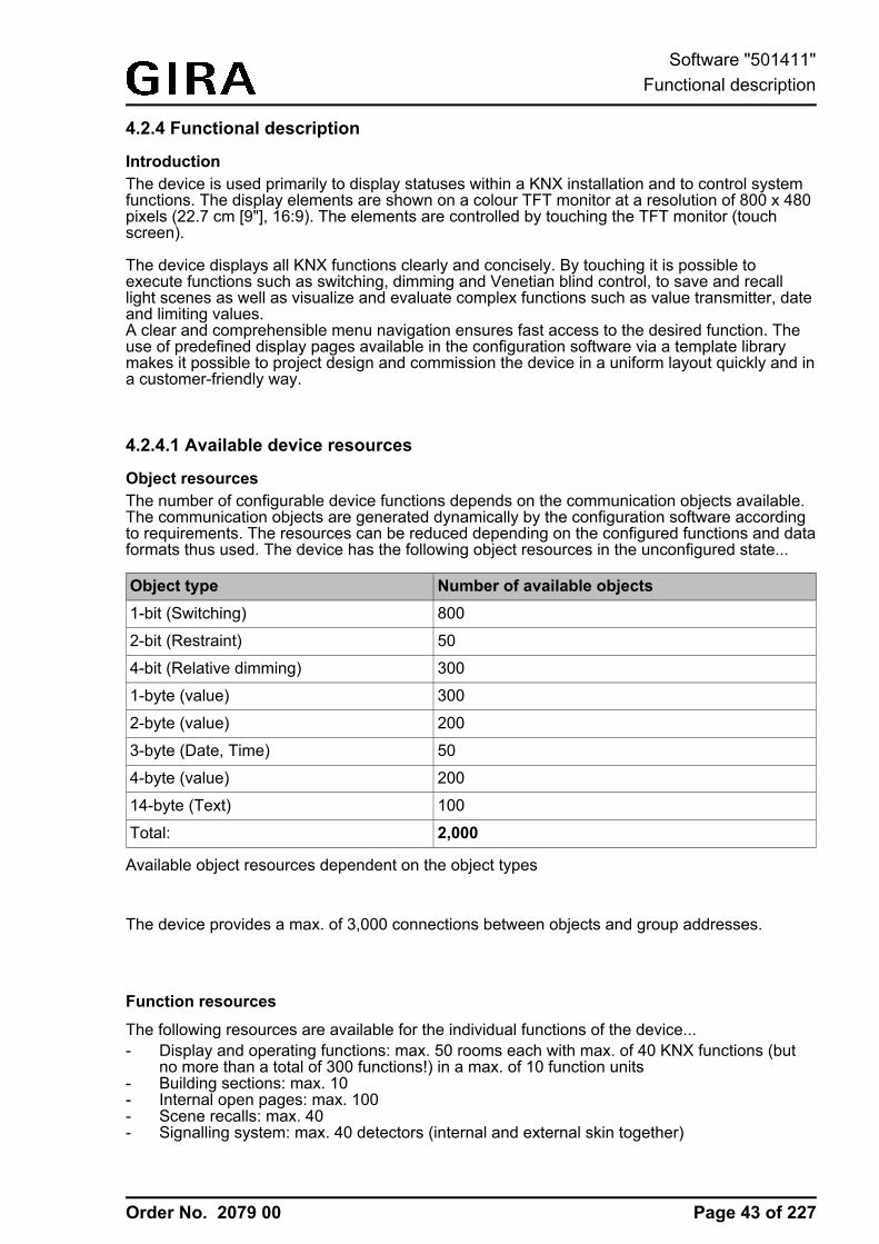
4.2.4 Functional description
IntroductionThe device is used primarily to display statuses within a KNX installation and to control systemfunctions. The display elements are shown on a colour TFT monitor at a resolution of 800 x 480pixels (22.7 cm [9"], 16:9). The elements are controlled by touching the TFT monitor (touchscreen).
The device displays all KNX functions clearly and concisely. By touching it is possible toexecute functions such as switching, dimming and Venetian blind control, to save and recalllight scenes as well as visualize and evaluate complex functions such as value transmitter, dateand limiting values.A clear and comprehensible menu navigation ensures fast access to the desired function. Theuse of predefined display pages available in the configuration software via a template librarymakes it possible to project design and commission the device in a uniform layout quickly and ina customer-friendly way.
4.2.4.1 Available device resources
Object resourcesThe number of configurable device functions depends on the communication objects available.The communication objects are generated dynamically by the configuration software accordingto requirements. The resources can be reduced depending on the configured functions and dataformats thus used. The device has the following object resources in the unconfigured state...
Object type Number of available objects1-bit (Switching) 800
2-bit (Restraint) 50
4-bit (Relative dimming) 300
1-byte (value) 300
2-byte (value) 200
3-byte (Date, Time) 50
4-byte (value) 200
14-byte (Text) 100
Total: 2,000
Available object resources dependent on the object types
The device provides a max. of 3,000 connections between objects and group addresses.
Function resources
The following resources are available for the individual functions of the device...- Display and operating functions: max. 50 rooms each with max. of 40 KNX functions (but
no more than a total of 300 functions!) in a max. of 10 function units- Building sections: max. 10- Internal open pages: max. 100- Scene recalls: max. 40- Signalling system: max. 40 detectors (internal and external skin together)
Page 43 of 227
Software "501411"Functional description
Order No. 2079 00
- Datalogger: max. 20 datalogger channels- Logic gates: max. 80 gates with up to 8 inputs and one output each- Timers: max. 40- Limiting value modules: max. 40- Demultiplexer "1 to 2" and "1 to 4": max. of 7 each- Timer: max 64 switching channels with a total of 128 switching times- Scenes: max. of 24 scenes, max. of 32 scene functions- Presence simulation: max. 8 simulations, max. 32 functions (15 functions per simulation)- Fault messages: max. 50- Event e-mails: max. 50- Video messages: max. 8i During commissioning, configured icons, images and audio files are transferred to the
device in the original file size and stored in the device RAM. To avoid having to commitlarge amounts of storage resources for these elements, the size of the icons and imagesshould be adapted to the display size of the screen in the display elements. In addition,audio files (e.g. acoustic signal of fault messages or text displays) should only containcontent with a short playback length.
Page 44 of 227
Software "501411"Functional description

Order No. 2079 00
4.2.4.2 Configuration software
4.2.4.2.1 Introduction, installation and program start
IntroductionThe Control KNX 9 is configured using the "Gira Control KNX Configuration Tool" andcommissioned. This configuration software is installed independent of the ETS and allows thegraphic configuration of display and operating elements and the configuration of thecommunication objects and function parameters to be simple and clear.An ETS product database that has an embedded plug-in is available for calibrating theconfiguration data of the ETS project (group addresses, visible communication objects). Thedata exchange between configuration software and ETS PlugIn takes place via an internalinterface (IP via local host).
Installation and program startThe configuration software is an executable EXE program that must be installed on the PCbefore using for the first time. For this reason, the program is supplied as installation package.Executing the installation package opens the Setup program, which provides an easy guidethrough the installation process and installs the configuration software correctly on the PC. i The configuration software can be run on PCs with the operating systems Windows® XP
SP3 (only 32-bit), Vista SP2, and 7 SP1 (32 and 64-bit respectively).CPU > 2 GHzRAM > 2 GBScreen resolution: at least 1024 x 768To obtain the best results, we strongly recommend using at least 4 GB RAM and a higherscreen resolution!
The configuration software can be opened after a successful installation operation. Opening ispossible - depending on the options selected or possible during installation - either by double-clicking the program icon on the desktop or, alternatively, via the Start menu or the Quick Startbar of the operating system.After starting the configuration software, a new project is first opened. This project can be usedas the basis for a new configuration if no project file is yet available.In the configuration software, a project file can be created or opened and saved in the "File"menu. A separate project file is required for each individual configuration of a device. For thisreason, when assigning a name to the project file (file ending: "*.gpct9"), a meaningful nameshould be selected to identify the configured device (e.g. "living room panel.gpct9"). Thefilename is assigned on saving.
Page 45 of 227
Software "501411"Functional description
Order No. 2079 00
4.2.4.2.2 Structure and operation
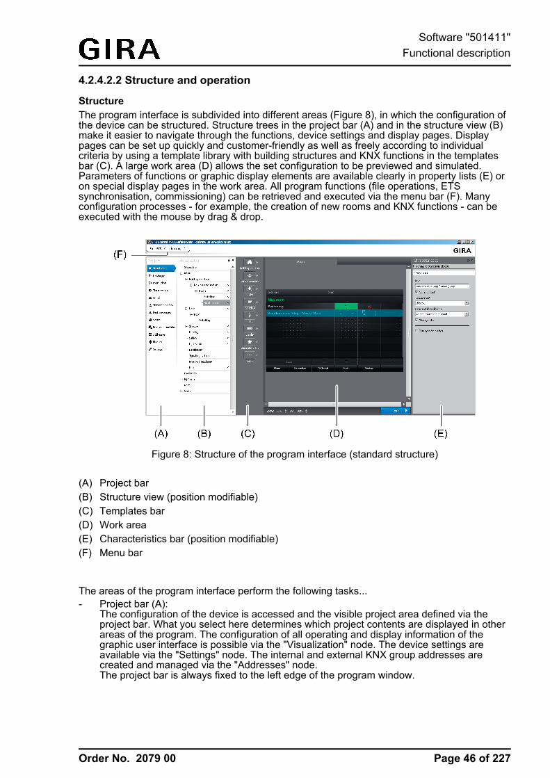
StructureThe program interface is subdivided into different areas (Figure 8), in which the configuration ofthe device can be structured. Structure trees in the project bar (A) and in the structure view (B)make it easier to navigate through the functions, device settings and display pages. Displaypages can be set up quickly and customer-friendly as well as freely according to individualcriteria by using a template library with building structures and KNX functions in the templatesbar (C). A large work area (D) allows the set configuration to be previewed and simulated.Parameters of functions or graphic display elements are available clearly in property lists (E) oron special display pages in the work area. All program functions (file operations, ETSsynchronisation, commissioning) can be retrieved and executed via the menu bar (F). Manyconfiguration processes - for example, the creation of new rooms and KNX functions - can beexecuted with the mouse by drag & drop.
Figure 8: Structure of the program interface (standard structure)
(A) Project bar(B) Structure view (position modifiable)(C) Templates bar(D) Work area(E) Characteristics bar (position modifiable)(F) Menu bar
The areas of the program interface perform the following tasks...- Project bar (A):
The configuration of the device is accessed and the visible project area defined via theproject bar. What you select here determines which project contents are displayed in otherareas of the program. The configuration of all operating and display information of thegraphic user interface is possible via the "Visualization" node. The device settings areavailable via the "Settings" node. The internal and external KNX group addresses arecreated and managed via the "Addresses" node.The project bar is always fixed to the left edge of the program window.
Page 46 of 227
Software "501411"Functional description
Order No. 2079 00
- Structure view (B):The structure of the configuration is shown in the structure view. Depending on theselection in the project bar, it is possible to navigate through all available project settings orfunction elements here. In the project area of the visualization, the project structure of theavailable display pages, for example, is displayed in the structure view (building andfunction unit pages, system pages). Therefore, rooms, function units and KNX functions arecreated and configured here. In other project areas, a systematic overview of settings orfunction elements is possible by means of the structure view (e.g. timer channels of thetimer or configured fault messages).The structure view in the standard view is arranged next to the project bar to the right. Itcan be detached from the program window and positioned anywhere on the PC screen oron another place in the window if required. Optionally, the structure view of the selectedprogram area can be closed ("X" in the header) so that it is hidden. A structure view can berestored if the entry of the structure view in the menu line (F) is selected again by clickingwith the right mouse button.Not all the nodes in the project bar require a structure view. The structure view is onlyavailable for project areas that require the systematic overview of settings or navigationthrough configuration elements.
- Templates bar (C):In the templates bar, which is only visible in the project area of the visualization, is thetemplates library for the configuration of the desired building and function unit structure andKNX functions. The templates for the project structure are assigned by drag & drop:Elements of the templates library are assigned to the structure view or directly to thedesignated positions in the work area (see page 48).
- Work area (D):The work area displays various types of information depending on which project area wasselected via the project bar.The work area is used as a preview of the configured graphic user interface in the projectarea of the visualization. It displays the corresponding display pages of the elementsselected in the structure view. In this way, the appearance of the control surfaces (buttons,rockers, value sliders), display areas (status texts and status symbols) and navigationelements can be visualized page by page and adjusted accordingly to the requirements.The rooms, function units, KNX functions and function pages visible in the display area areselected by mouse click whereby the characteristics of the selected elements are displayeddirectly in the other program areas (D), (E). In this way, quick and easy navigation ispossible through the building structure, display and operating functions and settings duringthe configuration.In the display area of the visualization a simulation of the graphic user interface can beexecuted. This makes it possible to already test and visualize all operating and displayfunctions during the configuration including real navigation through the display pages. Theuser interface in the simulation can be used in a similar way as on the device aftercommissioning. Unlike local control, however, no KNX telegrams can be transmitted orevaluated. Even some functions whose statuses are controlled by bus telegrams (e.g. thesignalling system or fault messages) can only be operated to a limited extent in thesimulation. The simulation is started by pressing the control surface "Start" in the footer ofthe work area. The simulation is stopped at the current position by clicking the mousebutton on the control surface "Stop". All other program areas of the configuration softwareare hidden during a simulation.In other project areas, the work area displays parameters for functions or function elements(e.g. timer channels of the timer or configured fault messages).The work area is always arranged in the centre of the program window. Its size variesdepending on the visibility of other program areas. The display area fills the entire programwindow in the simulation.
Page 47 of 227
Software "501411"Functional description
Order No. 2079 00
- Characteristics bar (E):The characteristics bar, which is only visible in the project area of the visualization,contains all parameters and communication objects for display pages and operating anddisplay elements of the graphic user interface. The characteristics bar displays allparameters and objects for the selected element depending on the selection in thestructure view or in the work area.The characteristics bar is subdivided into two areas. The first area always contains all KNXobjects and normally parameters that define communication characteristics (e.g.parameters for defining data formats and operating times, password protection settings ofdisplay pages). The second area contains parameters that influence the representation ofthe display and operating elements (e.g. name of display pages, image texts, symboldefinitions, assignments to function units, value formats).The characteristics bar in the default view is arranged on the right edge of the programwindow. It can be detached from the program window and positioned anywhere on the PCscreen or on another place in the window if required. Optionally, the characteristics bar canbe closed ("X" in the header) so that it is hidden. The bar can be restored if the entry of thecharacteristics in the menu line (F) is selected again by clicking with the right mousebutton.
- Menu bar (F):All program functions can be retrieved and executed via the menu bar. This includes fileoperations, the ETS synchronisation as well as the commissioning by data exchange or IPcommunication.
OperationThe configuration software has been designed so that many configuration processes can beexecuted with the mouse by drag & drop. Particularly the configuration of the visualization - forexample the creation of new rooms and KNX functions - is carried out in this simple way.Parameters for the different device functions are set similarly to the ETS for the most part:Parameters - depending on the functions to be configured - are either available in list form in thework area or in the area of the settings and divided into categories depending on the functions.
Configuration of the VisualizationIn the templates bar, which is only visible in the project area of the visualization, is the templateslibrary for the configuration of the desired building and function unit structure and KNX functions.The templates for the project structure are assigned by drag & drop: Elements of the templateslibrary are assigned to the structure view or directly to the designated positions in the work area.The following images show by way of example the creation of a new room and KNX function"Switching" in the standard function unit "Light".i The example shows the creation of a new building structure and KNX function into the
structure view by drag & drop. Alternatively, these elements can also be inserted into thegraphic user interface by drag & drop in the work area.
Page 48 of 227
Software "501411"Functional description
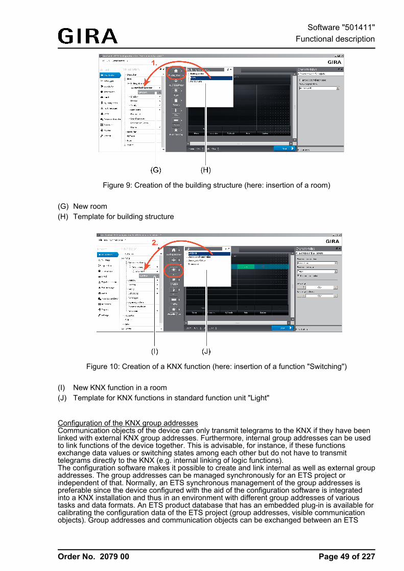
Order No. 2079 00
Figure 9: Creation of the building structure (here: insertion of a room)
(G) New room(H) Template for building structure
Figure 10: Creation of a KNX function (here: insertion of a function "Switching")
(I) New KNX function in a room(J) Template for KNX functions in standard function unit "Light"
Configuration of the KNX group addressesCommunication objects of the device can only transmit telegrams to the KNX if they have beenlinked with external KNX group addresses. Furthermore, internal group addresses can be usedto link functions of the device together. This is advisable, for instance, if these functionsexchange data values or switching states among each other but do not have to transmittelegrams directly to the KNX (e.g. internal linking of logic functions).The configuration software makes it possible to create and link internal as well as external groupaddresses. The group addresses can be managed synchronously for an ETS project orindependent of that. Normally, an ETS synchronous management of the group addresses ispreferable since the device configured with the aid of the configuration software is integratedinto a KNX installation and thus in an environment with different group addresses of varioustasks and data formats. An ETS product database that has an embedded plug-in is available forcalibrating the configuration data of the ETS project (group addresses, visible communicationobjects). Group addresses and communication objects can be exchanged between an ETS
Page 49 of 227
Software "501411"Functional description
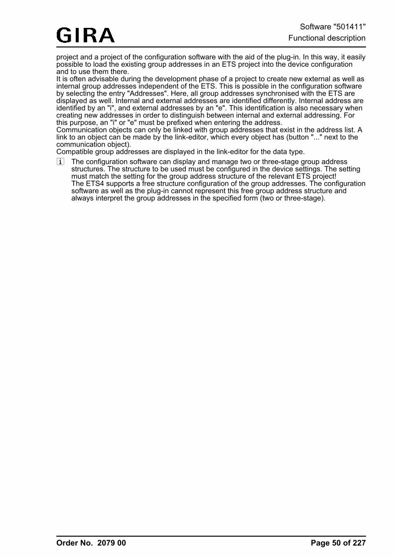
Order No. 2079 00
project and a project of the configuration software with the aid of the plug-in. In this way, it easilypossible to load the existing group addresses in an ETS project into the device configurationand to use them there.It is often advisable during the development phase of a project to create new external as well asinternal group addresses independent of the ETS. This is possible in the configuration softwareby selecting the entry "Addresses". Here, all group addresses synchronised with the ETS aredisplayed as well. Internal and external addresses are identified differently. Internal address areidentified by an "i", and external addresses by an "e". This identification is also necessary whencreating new addresses in order to distinguish between internal and external addressing. Forthis purpose, an "i" or "e" must be prefixed when entering the address.Communication objects can only be linked with group addresses that exist in the address list. Alink to an object can be made by the link-editor, which every object has (button "..." next to thecommunication object).Compatible group addresses are displayed in the link-editor for the data type.i The configuration software can display and manage two or three-stage group address
structures. The structure to be used must be configured in the device settings. The settingmust match the setting for the group address structure of the relevant ETS project!The ETS4 supports a free structure configuration of the group addresses. The configurationsoftware as well as the plug-in cannot represent this free group address structure andalways interpret the group addresses in the specified form (two or three-stage).
Page 50 of 227
Software "501411"Functional description
Order No. 2079 00
4.2.4.2.3 Data comparison with ETS
IntroductionAn ETS product database that has an embedded plug-in is available for calibrating theconfiguration data of the ETS project (group addresses, visible communication objects). Groupaddresses and communication objects can be exchanged between an ETS project and a projectof the configuration software with the aid of the plug-in. In this way, it easily possible on onehand to load the group addresses available in an ETS project into the device configuration andto use it there. On the other hand, addresses that were created in the configuration software canbe transferred to the ETS project by the synchronisation process.The ETS-Synchronisation is able to detect conflicts with group addresses. Conflicts will thenarise, for example, if group addresses in the configuration software are created independent ofthe ETS and are linked with objects, these addresses already use other data formats in the ETSprojects, however.Within the ETS (Project view), all configured objects of the device are each displayedindependently with allocated group addresses after a data comparison depending on the dataformat. Dynamic objects of the visualisation are displayed independent of function, i.e. theobjects are not identified with unique names. For predefined functions (e.g. signalling system orpresence simulation) the affiliated objects are labelled dependent on function.Group addresses may only be linked with communication objects in the configuration software!The data management in the ETS project is only for maintaining the address table (specificationof the data formats) and for generating filter tables for backbone/line couplers.i The device is only commissioned by the configuration software. The ETS product database
cannot be used to load the application program into the device. The plug-in preventsprogramming of the application data by the ETS.The physical address of the device can also be programmed using the application program.
Performing synchronisationSynchronisation by means of ETS must be performed in a defined order. The steps describedbelow explain the procedure for performing a synchronisation of group addresses andcommunication objects with an ETS project.A synchronisation should take place at the beginning of the device configuration when an ETSproject with group addresses already exists. During the progress of a project design, it isadvisable to perform a synchronisation with the ETS regularly in order to detect group addressconflicts at an early stage or to reduce the configuration work as much as possible whencreating new group addresses. After completing the device configuration in the configurationsoftware, an ETS synchronisation should always be performed so that all objects and groupaddresses used are synchronised with the ETS project.Synchronisation of the device configuration with the ETS requires that a device in thecorresponding ETS project was inserted at the designated position of the topology by means ofthe product database. Ideally, a physical address should have been assigned to the device inthe project and programmed.The ETS and configuration software must be opened with the designated projects.o Step 1: In the configuration software, recall the entry "Synchronise ETS -> ETS" in the
menu.A program window will open displaying the standby mode of the ETS synchronisation.
o Step 2: Change to the ETS. In the ETS project, recall the parameter view of the deviceentry.The plug-in is started.
o Step 3: Click on the "Search configuration tool" button.
Page 51 of 227
Software "501411"Functional description
Order No. 2079 00
The plug-in attempts to establish communication with the configuration software. If theconnecting process is successful, the plug-in identifies the configuration software, readsout the project design and displays in the left-hand list window the device name and deviceinformation of the project design found. If the ETS could already successfully synchronisethe project design once, the device name of the selected project design will correspond tothe name of the device in the ETS project. The device information then displays thephysical address of the device that was configured at the time of the last synchronisation. Ifthe project design has not yet been synchronised with the ETS, a standard device name isdisplayed and the device information indicates "new".Next to the list window on the right, the plug-in displays more information in tabular form inthe reading area regarding the project design read out and the device entry of the ETSproject. By comparing this information it is possible to determine whether the correct projectdesign was selected and when the last synchronisation took place.
i It is possible to activate several configuration tools in the ETS-Synchronisation. The plug-inalways finds all the tools that are in synchronisation state. This is advisable, for instance, ifthere are different devices in a KNX installation that have to be synchronised in the ETSproject with different device entries. In this case, a separate synchronisation process mustbe performed for each device entry in the ETS project.
i ETS and configuration software must always be on the same PC. The data exchangebetween ETS and configuration software takes place in the operating system via IPcommunication (local host / IPv4: 127.0.0.1). If a firewall is installed on the PC, it must beensured that communication via local host is not prevented.
o Step 4: Once it is certain that the correct project design and device entry were selected inthe ETS project, the synchronisation can be resumed. To do this, click on the projectdesign to be synchronised in the left-hand list window and then click on the "Synchronise"button.The plug-in reads more details of the project design and displays them in a new window. Inthe left window area, the objects and group addresses read out from the device entry of theETS project are displayed. In the middle area, the window displays the information read outfrom the project design.
o Step 5: Press the "Compare" button.The plug-in compares the project design read out from the configuration software with theETS project. The comparison result is displayed in the left window area.If address conflicts (data formats that do not match each other) were detected, the plug-inhighlights these conflicts in colour and displays a warning message. After confirming thewarning message, it is possible to save the conflicts in text form by clicking on the "Saveconflicts" button. The synchronisation process cannot then be executed until the end. Allconflicts must first be removed manually by intervening in the project design. Only then cana new synchronisation process be resumed without interruption.
o Step 6: If no conflicts were detected in group addresses, the "Merge" button can be clickedon to resume the synchronisation.The plug-in then harmonises all objects and group addresses and updates the window areaas a preview.
o Step 7: Finally, the harmonised project design can be applied in the ETS project and in theproject design. To do this, the "Apply" button must be pressed.Objects of the project design are added to the ETS project. Group addresses aretransferred from the ETS project to the project design and/or from the project design to theETS project. The plug-in writes the device name, description and physical address from theETS project as well as the ETS project name in the project of the configuration software sothat identification is possible at the beginning of a new synchronisation process (see setup3).The synchronisation is terminated after the transfer process has successfully run withoutany errors. In the configuration software, the standby mode of the ETS-Synchronisation isthen terminated automatically. The plug-in can be closed.
Page 52 of 227
Software "501411"Functional description
Order No. 2079 00
i If a synchronisation in the plug-in is cancelled before the end, this must also be cancelledmanually in the configuration software before a new synchronisation can be executed. Thereverse is true in like manner.
Page 53 of 227
Software "501411"Functional description
Order No. 2079 00
4.2.4.2.4 Commissioning
IntroductionCommissioning of the device is possible by IP programming connection via the Ethernetinterface or alternatively via memory access (USB memory stick, SD card, network drive). Whenperforming a commissioning, the configuration is transferred from the configuration software to adevice. After successful transfer by IP or memory access, the target device re-startsautomatically and thereby directly applies the new programmed configuration.Besides the programming of a configuration, the readout is possible, too. A readout can beperformed for the purpose of reconstruction, for example. Here, an IP connection to the devicecan be established, the existing configuration read out and transferred to the project of theconfiguration software. Alternatively, it is possible to read out an existing configuration in adevice by memory access.i To ensure that commissioning by an IP programming connection is possible, the device
must be connected to a network via the Ethernet interface and the KNX applicationexecuted in the device. It is not necessary here to recall a specific display page.
i If a firewall is installed on the commissioning PC, this must enable the IP access for theconfiguration software. Otherwise, an IP programming connection to the device will not bepossible. A firewall normally displays blocked programs when these programs are installedor started. Should this be the case when installing or starting the configuration software, besure to adapt the configuration of the firewall without fail!
i During commissioning by means of IP, the existing devices are searched for in the firststep. This broadcast search is performed by UDP (User Datagram Protocol) via port 13.The programming connection takes place in the next step by TCP/IP (Transmission ControlProtocol / Internet Protocol) via IP port 8080.
i To ensure that a commissioning by an IP programming connection is possible, the IPsettings in the Windows® operating system must be configured correctly on the device andon the commissioning PC. This includes the device's own IP address, the sub-networkmask, the addresses of the standard gateway (e.g. Internet router) and a valid DNS serveras well as settings for an optionally available firewall or proxy server.To change to the Windows® operating system on the device, the KNX application thatshould always be in the foreground in normal operation must be minimized or eventerminated. It is possible to terminate the KNX application by briefly pressing the ON/OFFbutton. In doing so, the device changes to the operating system and displays the desktop.The KNX application can be minimized via the Windows taskbar. The Windows taskbar isnormally in the background and is therefore not visible. The taskbar can be accessed byconnecting a USB keyboard.
Commissioning and reconstruction by IP programming connection or memory access isdescribed in the following sections.
Commissioning by means of IPCommissioning by means of IP must be performed in a defined order. The steps describedbelow explain the procedure for performing a commissioning by means of IP.The configuration software must be opened with the designated project. The device mustalready be switched on and be ready for operation.o Step 1: In the configuration software, recall the entry "Commissioning -> Transfer -> IP" in
the menu.The configuration software first saves the current project. To do this, a file name must bespecified if you have not already done so. The configuration software then searches in thenetwork for available devices by means of IP broadcast. After the search procedure iscompleted, a window for device selection will open. In this window, devices can beidentified using their name, physical address of the IP address and the MAC address.
Page 54 of 227
Software "501411"Functional description
Order No. 2079 00
i The device name displayed in the device selection corresponds to the computer nameregistered in the Windows® operating system. It can be suitably adapted directly on thedevice if required.
i Next to the device selection on the right is a button for updating the view. This allows a newIP broadcast device search procedure to be triggered.
o Step 2: In the device selection list, select the target device to be programmed by a simplemouse click. After that, click on the "Start" button. Alternatively, the list entry of the targetdevice can be selected by a double mouse click.The configuration software establishes an IP programming connection to the device andprompts you to enter the password for commissioning by means of IP.
o Step 3: Enter the password for commissioning by means of IP.The configuration software loads the configuration into the target device. Afterwards, thedevice re-starts automatically and applies the programmed configuration. This completesthe commissioning process.
i The configuration software allows the password to be entered incorrectly a maximum ofthree times. After entering the password incorrectly a fourth time, the configuration softwarewill abort the commissioning operation.
i The password for the commissioning by means of IP is not defined in the configurationsoftware. It is only saved in the device and must also be changed there. Passwords can becustomized in the submenu "Settings". It is advisable to activate the password protectionfor the display page of the passwords so that the setting of new passwords is protectedagainst unauthorised access. This is done by assigning the display page in theconfiguration software to a password level.
Commissioning by means of memory accessIn the case of commissioning by means of memory access, the project data created in theconfiguration software and saved in a commissioning file must be imported to the device. This ispossible directly on the device in the user and system settings.Commissioning by means of memory access must be performed in a defined order. The stepsdescribed below explain the procedure for performing a commissioning by means of memoryaccess.The configuration software must be opened with the designated project.o Step 1: In the configuration software, recall the entry "Commissioning -> Transfer -> File" in
the menu.The configuration software first saves the current project. To do this, a file name must bespecified if you have not already done so. Afterwards, the configuration software promptsfor a file name and the storage location for the commissioning file. A commissioning file hasthe file ending "*.gdct9".The configuration file is created and saved at the predefined storage location.
o Step 2: On the device; go to the user and system settings and choose the menu item forimporting a configuration (see page 122-123). Import the commissioning file savedpreviously.The device imports the commissioning. It then re-starts automatically. This completes thecommissioning process.
Reconstruction by means of IPA reconstruction by means of IP must be performed in a defined order. The steps describedbelow explain the procedure for performing a reconstruction by means of IP.The configuration software must be opened. The device must already be switched on and beready for operation.
Page 55 of 227
Software "501411"Functional description
Order No. 2079 00
o Step 1: In the configuration software, recall the entry "Commissioning -> Reconstruction ->IP" in the menu.The configuration software searches in the network for available devices by means of IPbroadcast. After the search procedure is completed, a window for device selection willopen. In this window, devices can be identified using their name, physical address of the IPaddress and the MAC address.
i The device name displayed in the device selection corresponds to the computer nameregistered in the Windows® operating system. It can be suitably adapted directly on thedevice if required.
i Next to the device selection on the right is a button for updating the view. This allows a newIP broadcast device search procedure to be triggered.
o Step 2: In the device selection list, select the device to be reconstructed by a simple mouseclick. After that, click on the "Start" button. Alternatively, the list entry of the device can beselected by a double mouse click.The configuration software establishes an IP connection to the device and prompts you toenter the password for commissioning by means of IP.
o Step 3: Enter the password for commissioning by means of IP.The configuration software reads out the configuration from the device. After the readoutprocedure is completed, the configuration software wants to transfer the readoutconfiguration to its own project. This means that the previous configuration will beoverwritten by the readout configuration. Consequently, the software will ask whether or notthe opened project should be saved. After confirmation, the configuration software will loadthe readout configuration to its own project. The reconstruction process is thus completed.
i The configuration software allows the password to be entered incorrectly a maximum ofthree times. After entering the password incorrectly a fourth time, the configuration softwarewill abort the commissioning operation.
i The password for the commissioning by means of IP is not defined in the configurationsoftware. It is only saved in the device and must also be changed there. Passwords can becustomized in the submenu "Settings". It is advisable to activate the password protectionfor the display page of the passwords so that the setting of new passwords is protectedagainst unauthorised access. This is done by assigning the display page in theconfiguration software to a password level.
i During the reconstruction process, the device can be used normally.
Reconstruction by means of memory accessIn the case of reconstruction by memory access, the project data exported by the device mustbe imported to the configuration software. The configuration that is active in the device can beexported directly on the device in the user and system settings.A reconstruction by means of memory access must be performed in a defined order. The stepsdescribed below explain the procedure for performing a reconstruction by means of memoryaccess.The device must already be switched on and be ready for operation.o Step 1: On the device go to the user and system settings and recall the menu item for
exporting a configuration (see page 122-123). Export the configuration. The exported filehas the file ending "*.gdct9".
o Step 2: In the configuration software, recall the entry "Commissioning -> Reconstruction ->File" in the menu. Specify the storage location of the project file to be imported and selectthe file.The configuration software reads out the configuration from the file. After the readoutprocedure is completed, the configuration software wants to transfer the readoutconfiguration to its own project. This means that the previous configuration will beoverwritten by the readout configuration. Consequently, the software will ask whether or notthe opened project should be saved. After confirmation, the configuration software will loadthe readout configuration to its own project. The reconstruction process is thus completed.
Page 56 of 227
Software "501411"Functional description
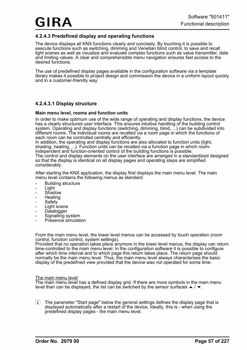
Order No. 2079 00
4.2.4.3 Predefined display and operating functionsThe device displays all KNX functions clearly and concisely. By touching it is possible toexecute functions such as switching, dimming and Venetian blind control, to save and recalllight scenes as well as visualize and evaluate complex functions such as value transmitter, dateand limiting values. A clear and comprehensible menu navigation ensures fast access to thedesired functions.
The use of predefined display pages available in the configuration software via a templatelibrary makes it possible to project design and commission the device in a uniform layout quicklyand in a customer-friendly way.
4.2.4.3.1 Display structure
Main menu level, rooms and function unitsIn order to make optimum use of the wide range of operating and display functions, the devicehas a clearly structured user interface. This ensures intuitive handling of the building controlsystem. Operating and display functions (switching, dimming, blind, ...) can be subdivided intodifferent rooms. The individual rooms are recalled via a room page in which the functions ofeach room can be controlled centrally and efficiently.In addition, the operating and display functions are also allocated to function units (light,shading, heating, ...). Function units can be recalled via a function page in which room-independent and function-oriented control of the building functions is possible.The control and display elements on the user interface are arranged in a standardized designedso that the display is identical on all display pages and operating steps are simplifiedconsiderably.
After starting the KNX application, the display first displays the main menu level. The mainmenu level contains the following menus as standard:- Building structure- Light- Shadow- Heating- Safety- Light scene- Datalogger- Signalling system- Presence simulation
From the main menu level, the lower level menus can be accessed by touch operation (roomcontrol, function control, system settings).Provided that no operation takes place anymore in the lower level menus, the display can returntime-controlled to the main menu level. In the configuration software it is possible to configureafter which time interval and to which page this return takes place. The return page shouldnormally be the main menu level. Thus, the main menu level always characterises the basicdisplay of the predefined view provided that the device was not operated for some time.
The main menu levelThe main menu level has a defined display grid. If there are more symbols in the main menulevel than can be displayed, the list can be switched by the sensor surfaces ¬ / ¯.
i The parameter "Start page" below the general settings defines the display page that isdisplayed automatically after a restart of the device. Ideally, this is - when using thepredefined display pages - the main menu level.
Page 57 of 227
Software "501411"Functional description
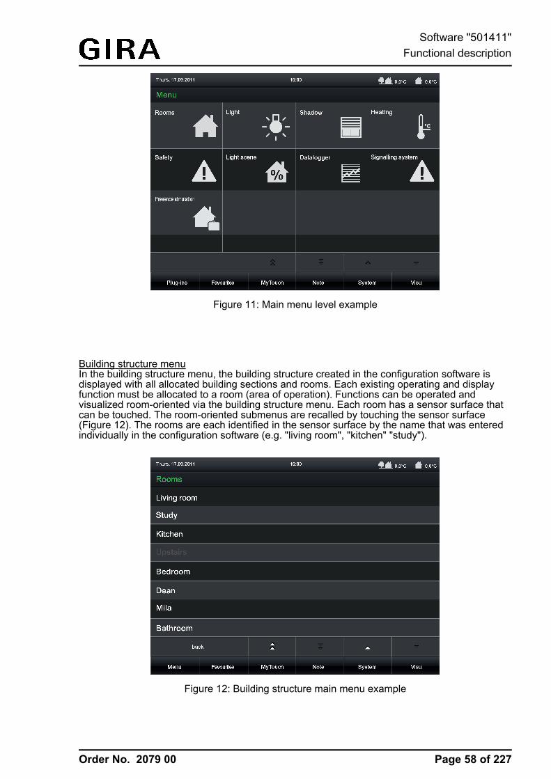
Order No. 2079 00
Figure 11: Main menu level example
Building structure menuIn the building structure menu, the building structure created in the configuration software isdisplayed with all allocated building sections and rooms. Each existing operating and displayfunction must be allocated to a room (area of operation). Functions can be operated andvisualized room-oriented via the building structure menu. Each room has a sensor surface thatcan be touched. The room-oriented submenus are recalled by touching the sensor surface(Figure 12). The rooms are each identified in the sensor surface by the name that was enteredindividually in the configuration software (e.g. "living room", "kitchen" "study").
Figure 12: Building structure main menu example
Page 58 of 227
Software "501411"Functional description
Order No. 2079 00
If more rooms are configured than can be displayed, the room list can be switched by thesensor surfaces ¬ / ¯.The building structure menu is always visible in the main menu level. Separate buttons fordirectly selecting the room can also be created there for each room created.
Light, shading, heating, security and light scene menuEach KNX function can be allocated to a function unit. Five standard function units arepredefined: "light", "shading", "heating", "security" and "light scene". All function units have theirown menus that are visible in the main menu level. It is possible to create additional functionunits in the configuration software with freely definable names.Furthermore, the device has additional functions which are independent of the five standardfunction units or of the user-defined function units that contain the KNX display and operatingfunctions. These functions are partially on the main menu level or can be recalled via thesubmenu system in the footer of the screen.
The supplementary functions available in the main menu level include...- the display page of the datalogger,
for capturing and visualizing data that can be determined in the configuration software;- the display page of the signalling system
for displaying detector statuses and switching events;- the display page of the presence simulation
for the playback of a simulated presence.The supplementary functions available in the submenu system in the footer of the screeninclude...- the application settings,
for editing light scenes, setting limiting values and recording and setting the presencesimulation;
- the system settings,for setting date, time and brightness, displaying the software version and resetting todefault settings;
- the user settings,for setting passwords, creating the e-mail account and commissioning;
- the display page of the fault messages,for displaying the history of the fault messages;
- starting the cleaning page,for cleaning the sensor surface; the touch sensitivity of the screen is switched off for 30seconds for this purpose;
- the display page of the service addresses,for displaying the service address;
- and the display page of the history,for displaying previous system events.
The display page of the video messages can be opened via the submenu Note in the footer ofthe screen.
Page 59 of 227
Software "501411"Functional description
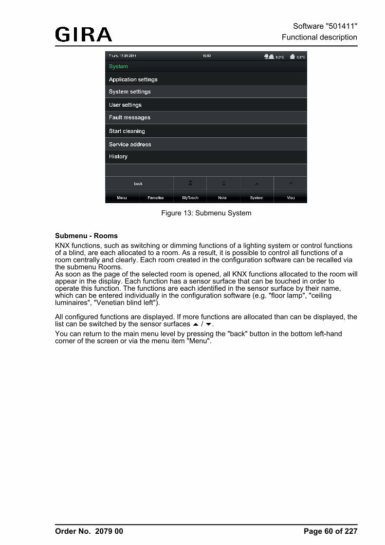
Order No. 2079 00
Figure 13: Submenu System
Submenu - RoomsKNX functions, such as switching or dimming functions of a lighting system or control functionsof a blind, are each allocated to a room. As a result, it is possible to control all functions of aroom centrally and clearly. Each room created in the configuration software can be recalled viathe submenu Rooms.As soon as the page of the selected room is opened, all KNX functions allocated to the room willappear in the display. Each function has a sensor surface that can be touched in order tooperate this function. The functions are each identified in the sensor surface by their name,which can be entered individually in the configuration software (e.g. "floor lamp", "ceilingluminaires", "Venetian blind left").
All configured functions are displayed. If more functions are allocated than can be displayed, thelist can be switched by the sensor surfaces ¬ / ¯.You can return to the main menu level by pressing the "back" button in the bottom left-handcorner of the screen or via the menu item "Menu".
Page 60 of 227
Software "501411"Functional description
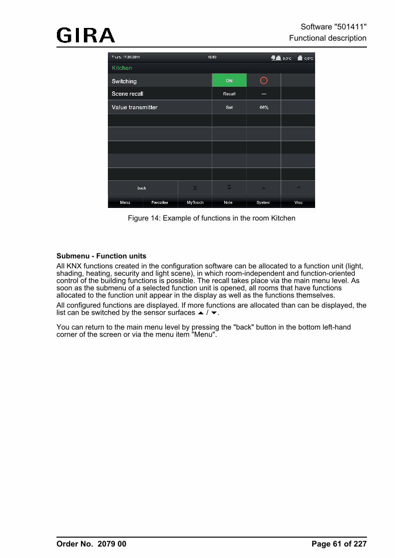
Order No. 2079 00
Figure 14: Example of functions in the room Kitchen
Submenu - Function unitsAll KNX functions created in the configuration software can be allocated to a function unit (light,shading, heating, security and light scene), in which room-independent and function-orientedcontrol of the building functions is possible. The recall takes place via the main menu level. Assoon as the submenu of a selected function unit is opened, all rooms that have functionsallocated to the function unit appear in the display as well as the functions themselves.All configured functions are displayed. If more functions are allocated than can be displayed, thelist can be switched by the sensor surfaces ¬ / ¯.
You can return to the main menu level by pressing the "back" button in the bottom left-handcorner of the screen or via the menu item "Menu".
Page 61 of 227
Software "501411"Functional description
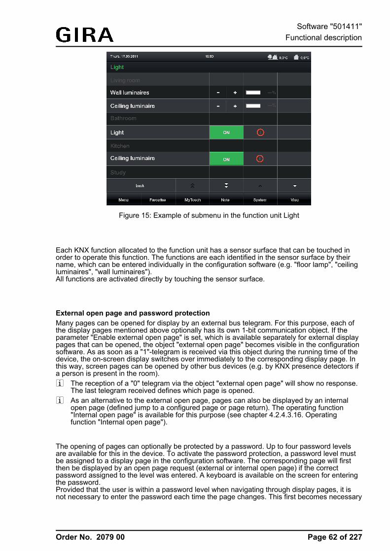
Order No. 2079 00
Figure 15: Example of submenu in the function unit Light
Each KNX function allocated to the function unit has a sensor surface that can be touched inorder to operate this function. The functions are each identified in the sensor surface by theirname, which can be entered individually in the configuration software (e.g. "floor lamp", "ceilingluminaires", "wall luminaires").All functions are activated directly by touching the sensor surface.
External open page and password protectionMany pages can be opened for display by an external bus telegram. For this purpose, each ofthe display pages mentioned above optionally has its own 1-bit communication object. If theparameter "Enable external open page" is set, which is available separately for external displaypages that can be opened, the object "external open page" becomes visible in the configurationsoftware. As as soon as a "1"-telegram is received via this object during the running time of thedevice, the on-screen display switches over immediately to the corresponding display page. Inthis way, screen pages can be opened by other bus devices (e.g. by KNX presence detectors ifa person is present in the room).i The reception of a "0" telegram via the object "external open page" will show no response.
The last telegram received defines which page is opened.i As an alternative to the external open page, pages can also be displayed by an internal
open page (defined jump to a configured page or page return). The operating function"Internal open page" is available for this purpose (see chapter 4.2.4.3.16. Operatingfunction "Internal open page").
The opening of pages can optionally be protected by a password. Up to four password levelsare available for this in the device. To activate the password protection, a password level mustbe assigned to a display page in the configuration software. The corresponding page will firstthen be displayed by an open page request (external or internal open page) if the correctpassword assigned to the level was entered. A keyboard is available on the screen for enteringthe password.Provided that the user is within a password level when navigating through display pages, it isnot necessary to enter the password each time the page changes. This first becomes necessary
Page 62 of 227
Software "501411"Functional description
Order No. 2079 00
when the user changes to a higher password level. When changing from a higher to a lowerpassword level, it is not necessary to enter the corresponding password.The activation of a password level after correctly entering the password remains active forapprox. 40 seconds. After this time has elapsed, the password of a level must be entered againwhen changing a page.i The display page of the signalling system and the commissioning by means of IP are
protected by their own passwords.i If an external open page is set, password protection is not possible for this page.i See also (see page 120-121)
Page 63 of 227
Software "501411"Functional description
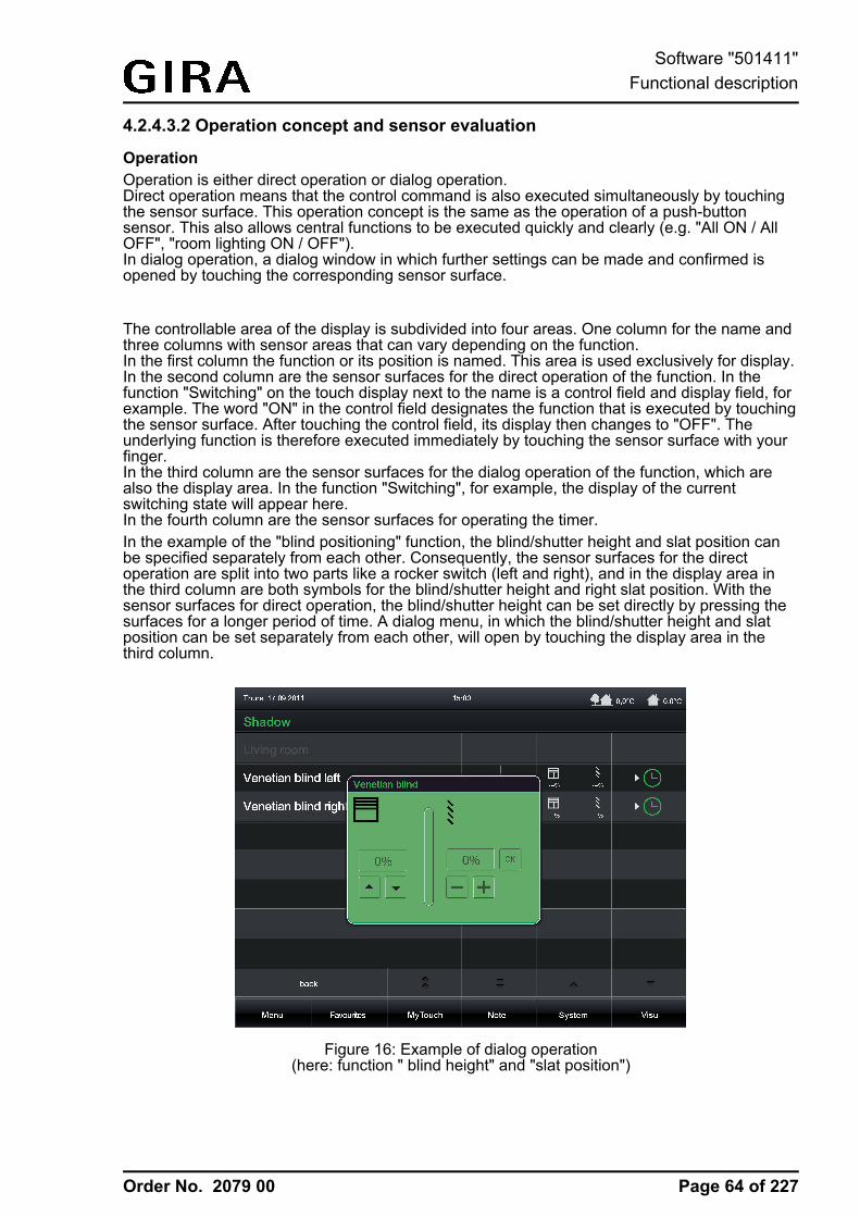
Order No. 2079 00
4.2.4.3.2 Operation concept and sensor evaluation
OperationOperation is either direct operation or dialog operation.Direct operation means that the control command is also executed simultaneously by touchingthe sensor surface. This operation concept is the same as the operation of a push-buttonsensor. This also allows central functions to be executed quickly and clearly (e.g. "All ON / AllOFF", "room lighting ON / OFF").In dialog operation, a dialog window in which further settings can be made and confirmed isopened by touching the corresponding sensor surface.
The controllable area of the display is subdivided into four areas. One column for the name andthree columns with sensor areas that can vary depending on the function.In the first column the function or its position is named. This area is used exclusively for display.In the second column are the sensor surfaces for the direct operation of the function. In thefunction "Switching" on the touch display next to the name is a control field and display field, forexample. The word "ON" in the control field designates the function that is executed by touchingthe sensor surface. After touching the control field, its display then changes to "OFF". Theunderlying function is therefore executed immediately by touching the sensor surface with yourfinger.In the third column are the sensor surfaces for the dialog operation of the function, which arealso the display area. In the function "Switching", for example, the display of the currentswitching state will appear here.In the fourth column are the sensor surfaces for operating the timer.In the example of the "blind positioning" function, the blind/shutter height and slat position canbe specified separately from each other. Consequently, the sensor surfaces for the directoperation are split into two parts like a rocker switch (left and right), and in the display area inthe third column are both symbols for the blind/shutter height and right slat position. With thesensor surfaces for direct operation, the blind/shutter height can be set directly by pressing thesurfaces for a longer period of time. A dialog menu, in which the blind/shutter height and slatposition can be set separately from each other, will open by touching the display area in thethird column.
Figure 16: Example of dialog operation(here: function " blind height" and "slat position")
Page 64 of 227
Software "501411"Functional description
Order No. 2079 00
i With some KNX functions (e.g. "Dimming brightness value" and "Venetian blind/shutterpositioning") the brightness value or blind/slat position can be adjusted to the valuetransmitter levels by means of a long operation of the sensor surfaces left and right or topand bottom operation (rocker function). In the functions "Dimming brightness value","Venetian blind positioning" and "Rolling shutter positioning", the value transmitter level ispreset to 10 %. In the function "Value transmitter adjustment function", the value transmitterlevel can be defined in the configuration software.
Sensor evaluation
Operation - depending on the underlying function - is either direct operation or dialog operation.The following KNX functions take place by direct operation...- Switching- Dimming Start/Stop- Venetian blind Step / Move / Step- Rolling shutter Step / Move- Scene requestThe following functions can also take place by means of dialog operation...- Dimming brightness value- Blind positioning- Rolling shutter positioning- Value transmitter- Operating mode switchover 4 x 1 bit- Operating mode switchover KNX- Restraint
In direct operation the operating element can be touched anywhere. The preset push-buttonfunction will then always be executed. In dialog operation the operating element is split into twosensor areas. These sensor areas are next to each other and must be operated separately fromeach other. It is not permissible to operate both sensor areas simultaneously.i The sensor areas for controllable KNX functions are represented by icons indicating the
command to be executed when touched. These operating icons are dependent on theconfigured function.
i Operating icons always indicate the two operational sensor areas (left / right).Consequently, two icons are then always visible. The visibility of the operating icons isdependent on the configured function and whether status elements are visible.
The commands transmitted to the bus during operation are predefined for some functions, forother functions the command can be configured in the configuration software.
The functions "KNX Date", "KNX Time", "Date / Time", "ASCII Text display" and "Collectivefeedback" are exclusively display functions. Consequently, these elements only display onestatus and cannot be operated.
i With the functions "Dimming brightness value", "Blind positioning" and "Rolling shutterpositioning" the value can be adjusted to the value transmitter levels by means of a longoperation of the sensor surfaces left and right. In the functions "Dimming brightness value","Venetian blind positioning" and "Rolling shutter positioning", the value transmitter level ispreset to 10 %. In the function "Value transmitter adjustment function", the value transmitterlevel can be defined in the configuration software.
Page 65 of 227
Software "501411"Functional description
Order No. 2079 00
i With the functions "dimming Start/Stop", "Venetian blind Step/Move/Step" and "rollingshutter Step / Move" a distinction is made between a short and long press of a sensorsurface. This is necessary in order to distinguish between the commands for switching anddimming and for short and long time operation. The actuation times can be defined in theconfiguration software. With the functions "Dimming brightness value", "Venetian blindpositioning" and "Rolling shutter positioning" the sensor surfaces can be pressed long forvalue adjustment.
i With the functions "Switching", "Value transmitter adjustment function", "Operating modeswitchover 4 x 1-bit" and "Operating mode switchover KNX" it is possible to switch off theoperating function completely. In this case, the KNX function concerned only works as adisplay function. Consequently, touching the display element does not induce anyresponse.
Page 66 of 227
Software "501411"Functional description
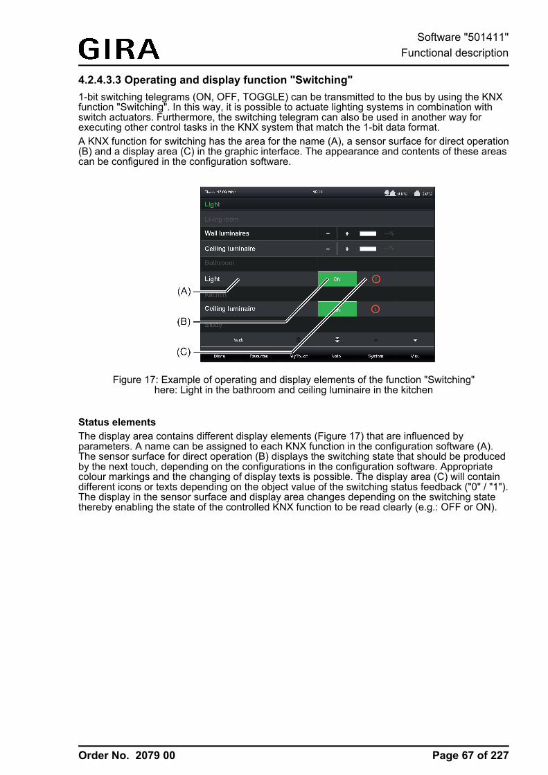
Order No. 2079 00
4.2.4.3.3 Operating and display function "Switching"1-bit switching telegrams (ON, OFF, TOGGLE) can be transmitted to the bus by using the KNXfunction "Switching". In this way, it is possible to actuate lighting systems in combination withswitch actuators. Furthermore, the switching telegram can also be used in another way forexecuting other control tasks in the KNX system that match the 1-bit data format.A KNX function for switching has the area for the name (A), a sensor surface for direct operation(B) and a display area (C) in the graphic interface. The appearance and contents of these areascan be configured in the configuration software.
Figure 17: Example of operating and display elements of the function "Switching"here: Light in the bathroom and ceiling luminaire in the kitchen
Status elementsThe display area contains different display elements (Figure 17) that are influenced byparameters. A name can be assigned to each KNX function in the configuration software (A).The sensor surface for direct operation (B) displays the switching state that should be producedby the next touch, depending on the configurations in the configuration software. Appropriatecolour markings and the changing of display texts is possible. The display area (C) will containdifferent icons or texts depending on the object value of the switching status feedback ("0" / "1").The display in the sensor surface and display area changes depending on the switching statethereby enabling the state of the controlled KNX function to be read clearly (e.g.: OFF or ON).
Page 67 of 227
Software "501411"Functional description
Order No. 2079 00
Objects
The function "Switching" has up to 2 KNX communication objects...
- "Switching" (1-bit transmitting and optional receiving):Switching telegrams are transmitted to the bus via this object after pressing the sensorelement. This can cause a switching channel of a KNX switch actuator to be activatedimmediately, for example.If the parameter "Use feedback object" is not selected, the switching state received via thisobject also influences the status indications. This is advisable, for instance, if the activatedKNX switch actuator does not have any separate feedback objects.
- "Switching feedback" (1-bit receiving):Through this object the device can receive a switching status feedback that a switchactuator transmits, for example. This influences the status text and status icon that can bedisplayed in the display area of the function element. The feedback of the switching statusmust be transmitted by the "actively transmitting" actuator.If the activated KNX switch actuator does not have a separate status feedback, theparameter "Use feedback object" can be deselected whereby the status indications areactivated via the object "Switching".
Page 68 of 227
Software "501411"Functional description
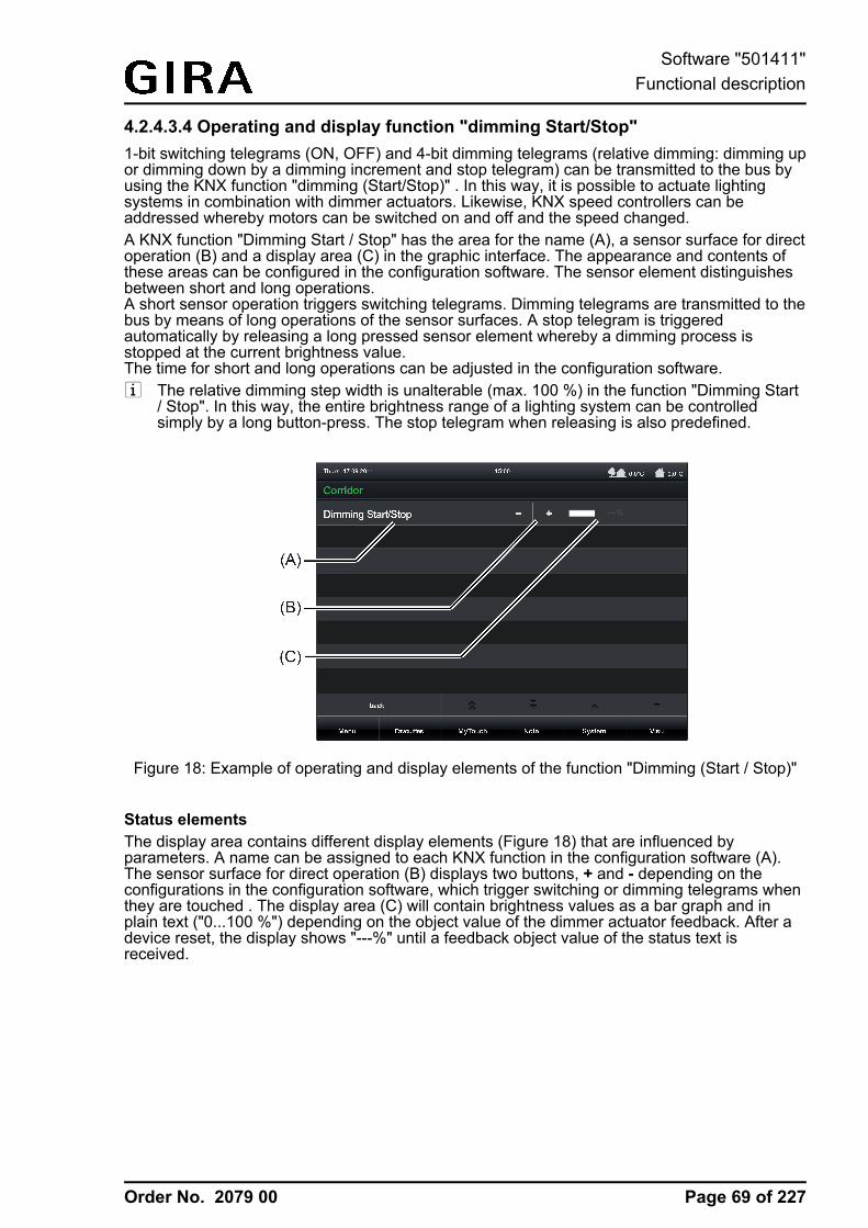
Order No. 2079 00
4.2.4.3.4 Operating and display function "dimming Start/Stop"1-bit switching telegrams (ON, OFF) and 4-bit dimming telegrams (relative dimming: dimming upor dimming down by a dimming increment and stop telegram) can be transmitted to the bus byusing the KNX function "dimming (Start/Stop)" . In this way, it is possible to actuate lightingsystems in combination with dimmer actuators. Likewise, KNX speed controllers can beaddressed whereby motors can be switched on and off and the speed changed.A KNX function "Dimming Start / Stop" has the area for the name (A), a sensor surface for directoperation (B) and a display area (C) in the graphic interface. The appearance and contents ofthese areas can be configured in the configuration software. The sensor element distinguishesbetween short and long operations.A short sensor operation triggers switching telegrams. Dimming telegrams are transmitted to thebus by means of long operations of the sensor surfaces. A stop telegram is triggeredautomatically by releasing a long pressed sensor element whereby a dimming process isstopped at the current brightness value.The time for short and long operations can be adjusted in the configuration software.i The relative dimming step width is unalterable (max. 100 %) in the function "Dimming Start
/ Stop". In this way, the entire brightness range of a lighting system can be controlledsimply by a long button-press. The stop telegram when releasing is also predefined.
Figure 18: Example of operating and display elements of the function "Dimming (Start / Stop)"
Status elementsThe display area contains different display elements (Figure 18) that are influenced byparameters. A name can be assigned to each KNX function in the configuration software (A).The sensor surface for direct operation (B) displays two buttons, + and - depending on theconfigurations in the configuration software, which trigger switching or dimming telegrams whenthey are touched . The display area (C) will contain brightness values as a bar graph and inplain text ("0...100 %") depending on the object value of the dimmer actuator feedback. After adevice reset, the display shows "---%" until a feedback object value of the status text isreceived.
Page 69 of 227
Software "501411"Functional description
Order No. 2079 00
Objects
The KNX function "dimming (Start/Stop)" has up to 3 KNX communication objects...
- "Switching (1-bit transmitting):Switching telegrams are transmitted to the bus via this object after a short touch of thesensor element. A connected lighting system, for example, is switched on as a result. KNXdimmer actuators then normally set the configured switch-on brightness.
- "Dimming (Start/Stop)" (4-bit transmitting):Dimming telegrams are transmitted to the bus via this object after a long press of thesensor element. A connected lighting system is dimmed as a result. A stop telegram istriggered via this object by releasing the sensor element.
- "Dimming feedback brightness value" (1-byte receiving):Through this object the device can receive a brightness value feedback that a dimmeractuator transmits, for example. The status value, status icon and bar graph are influencedas a result. Consequently, the feedback object must always be configured properly so thatthe status indications of the channel element work correctly if these are visible. Thefeedback of the brightness value must be transmitted by the "actively transmitting" actuator.If the activated KNX dimmer actuator does not have a separate brightness value feedback,the parameter "Use feedback object" can be deselected whereby all the status indicationsare then no longer available either, however.
i The object "Dimming feedback brightness value" interprets received values on the basis ofthe KNX data point type 5.001 (Scaling). The decimal data values 0...255 are evaluated aspercentages 0...100 % and displayed in the device display.
i Dimmer actuators normally transmit brightness values as feedback when the dimmingprocesses have been completed, i.e. when dimmed or started brightness values have beenset valid. For this reason, status indications of the channel element concerned do notnormally change during a press of the sensor surface, but only when the buttons arereleased and the dimming processes are stopped. By contrast, a displayed status valuecan already change even during an operation if the dimmer actuator has set a minimum ormaximum brightness or cannot pass through the entire brightness range due to disablingfunctions.The feedback of a brightness value is returned with a delay after switching on or off basedon the dimming speed set in the dimmer actuator. As a result, the status indications of theKNX function update themselves with a slight delay after releasing the sensor surfaces.
Page 70 of 227
Software "501411"Functional description
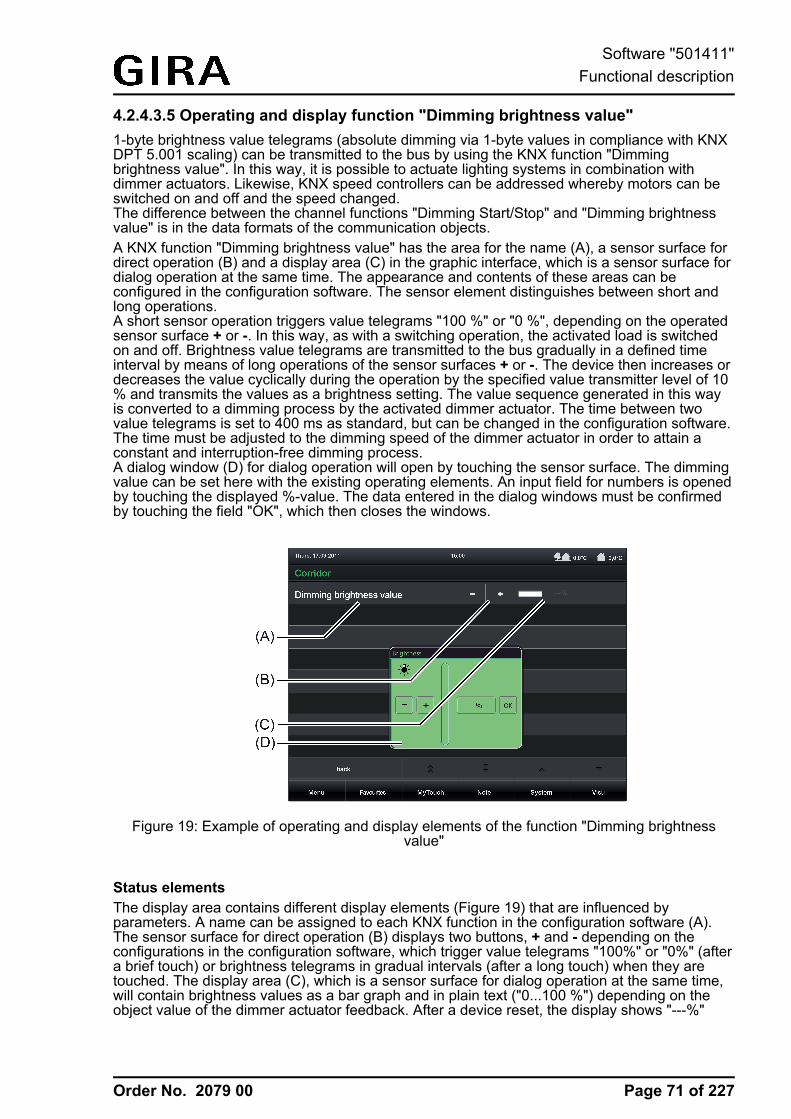
Order No. 2079 00
4.2.4.3.5 Operating and display function "Dimming brightness value"1-byte brightness value telegrams (absolute dimming via 1-byte values in compliance with KNXDPT 5.001 scaling) can be transmitted to the bus by using the KNX function "Dimmingbrightness value". In this way, it is possible to actuate lighting systems in combination withdimmer actuators. Likewise, KNX speed controllers can be addressed whereby motors can beswitched on and off and the speed changed.The difference between the channel functions "Dimming Start/Stop" and "Dimming brightnessvalue" is in the data formats of the communication objects.A KNX function "Dimming brightness value" has the area for the name (A), a sensor surface fordirect operation (B) and a display area (C) in the graphic interface, which is a sensor surface fordialog operation at the same time. The appearance and contents of these areas can beconfigured in the configuration software. The sensor element distinguishes between short andlong operations.A short sensor operation triggers value telegrams "100 %" or "0 %", depending on the operatedsensor surface + or -. In this way, as with a switching operation, the activated load is switchedon and off. Brightness value telegrams are transmitted to the bus gradually in a defined timeinterval by means of long operations of the sensor surfaces + or -. The device then increases ordecreases the value cyclically during the operation by the specified value transmitter level of 10% and transmits the values as a brightness setting. The value sequence generated in this wayis converted to a dimming process by the activated dimmer actuator. The time between twovalue telegrams is set to 400 ms as standard, but can be changed in the configuration software.The time must be adjusted to the dimming speed of the dimmer actuator in order to attain aconstant and interruption-free dimming process.A dialog window (D) for dialog operation will open by touching the sensor surface. The dimmingvalue can be set here with the existing operating elements. An input field for numbers is openedby touching the displayed %-value. The data entered in the dialog windows must be confirmedby touching the field "OK", which then closes the windows.
Figure 19: Example of operating and display elements of the function "Dimming brightnessvalue"
Status elementsThe display area contains different display elements (Figure 19) that are influenced byparameters. A name can be assigned to each KNX function in the configuration software (A).The sensor surface for direct operation (B) displays two buttons, + and - depending on theconfigurations in the configuration software, which trigger value telegrams "100%" or "0%" (aftera brief touch) or brightness telegrams in gradual intervals (after a long touch) when they aretouched. The display area (C), which is a sensor surface for dialog operation at the same time,will contain brightness values as a bar graph and in plain text ("0...100 %") depending on theobject value of the dimmer actuator feedback. After a device reset, the display shows "---%"
Page 71 of 227
Software "501411"Functional description
Order No. 2079 00
until a feedback object value of the status text is received.A dialog window (D) for dialog operation where the dimming value can be entered directly willopen by touching the sensor surface.
Objects
The KNX function "Dimming brightness value" has up to 2 KNX communication objects...
- "Dimming brightness value" (1-byte transmitting and optional receiving):Value telegrams are transmitted to the bus via this object after pressing the sensorelements. This can cause a dimmer actuator to be activated.If the parameter "Use feedback object" is not selected, the brightness value received viathis object also influences the status indications. This is advisable, for instance, if theactivated KNX dimmer actuator does not have any separate brightness value feedbackobjects.
- "Dimming feedback brightness value" (1-byte receiving):Through this object the device can receive a brightness value feedback that a dimmeractuator transmits, for example. The status value, status icon and bar graph are influencedas a result. The feedback of the brightness value must be transmitted by the "activelytransmitting" actuator.If the activated KNX dimmer actuator does not have a separate brightness value feedback,the parameter "Use feedback object" can be deselected whereby the status indications areactivated via the object "Brightness object".
i The objects interpret values to be sent or received on the basis of the KNX data point type5.001 (Scaling). The decimal data values 0...255 are evaluated as percentages 0...100 %.
i During an operation, the value of the object "Dimming feedback brightness value" is notevaluated. With a long press of the sensor elements + / - or when moving the slider, acontinuous value adjustment can take place on the bus. During this value adjustment, allstatus elements of the channel element are updated continuously by value simulation. Thedisplay elements first react again to the feedback object value of the dimmer actuator aftera short waiting time once the operation has been completed.
Page 72 of 227
Software "501411"Functional description
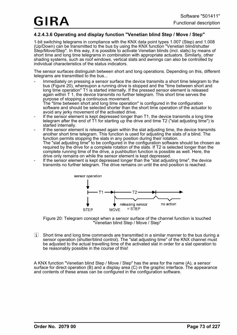
Order No. 2079 00
4.2.4.3.6 Operating and display function "Venetian blind Step / Move / Step"1-bit switching telegrams in compliance with the KNX data point types 1.007 (Step) and 1.008(Up/Down) can be transmitted to the bus by using the KNX function "Venetian blind/shutterStep/Move/Step". In this way, it is possible to activate Venetian blinds (incl. slats) by means ofshort time and long time telegrams in combination with appropriate actuators. Similarly, othershading systems, such as roof windows, vertical slats and awnings can also be controlled byindividual characteristics of the status indicators.
The sensor surfaces distinguish between short and long operations. Depending on this, differenttelegrams are transmitted to the bus...- Immediately on pressing a sensor surface the device transmits a short time telegram to the
bus (Figure 20), whereupon a running drive is stopped and the "time between short andlong time operation" T1 is started internally. If the pressed sensor element is releasedagain within T 1, the device transmits no further telegram. This short time serves thepurpose of stopping a continuous movement.The "time between short and long time operation" is configured in the configurationsoftware and should be selected shorter than the short time operation of the actuator toavoid any jerky movement of the activated drive.
- If the sensor element is kept depressed longer than T1, the device transmits a long timetelegram after the end of T1 for starting up the drive and time T2 ("slat adjusting time") isstarted internally.
- If the sensor element is released again within the slat adjusting time, the device transmitsanother short time telegram. This function is used for adjusting the slats of a blind. Thefunction permits stopping the slats in any position during their rotation.The "slat adjusting time" to be configured in the configuration software should be chosen asrequired by the drive for a complete rotation of the slats. If T2 is selected longer than thecomplete running time of the drive, a pushbutton function is possible as well. Here, thedrive only remains on while the sensor element is kept depressed.
- If the sensor element is kept depressed longer than the "slat adjusting time", the devicetransmits no further telegram. The drive remains on until the end position is reached.
Figure 20: Telegram concept when a sensor surface of the channel function is touched"Venetian blind Step / Move / Step"
i Short time and long time commands are transmitted in a similar manner to the bus during asensor operation (shutter/blind control). The "slat adjusting time" of the KNX channel mustbe adjusted to the actual travelling time of the activated slat in order for a slat operation tobe reasonably possible in the course of this!
A KNX function "Venetian blind Step / Move / Step" has the area for the name (A), a sensorsurface for direct operation (B) and a display area (C) in the graphic interface. The appearanceand contents of these areas can be configured in the configuration software.
Page 73 of 227
Software "501411"Functional description
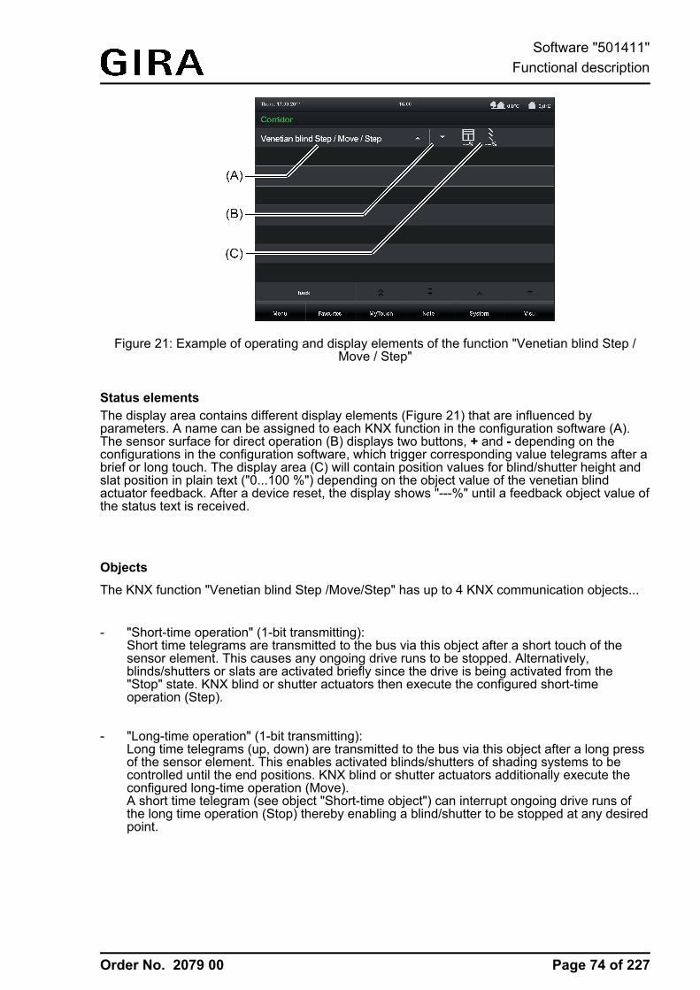
Order No. 2079 00
Figure 21: Example of operating and display elements of the function "Venetian blind Step /Move / Step"
Status elementsThe display area contains different display elements (Figure 21) that are influenced byparameters. A name can be assigned to each KNX function in the configuration software (A).The sensor surface for direct operation (B) displays two buttons, + and - depending on theconfigurations in the configuration software, which trigger corresponding value telegrams after abrief or long touch. The display area (C) will contain position values for blind/shutter height andslat position in plain text ("0...100 %") depending on the object value of the venetian blindactuator feedback. After a device reset, the display shows "---%" until a feedback object value ofthe status text is received.
Objects
The KNX function "Venetian blind Step /Move/Step" has up to 4 KNX communication objects...
- "Short-time operation" (1-bit transmitting):Short time telegrams are transmitted to the bus via this object after a short touch of thesensor element. This causes any ongoing drive runs to be stopped. Alternatively,blinds/shutters or slats are activated briefly since the drive is being activated from the"Stop" state. KNX blind or shutter actuators then execute the configured short-timeoperation (Step).
- "Long-time operation" (1-bit transmitting):Long time telegrams (up, down) are transmitted to the bus via this object after a long pressof the sensor element. This enables activated blinds/shutters of shading systems to becontrolled until the end positions. KNX blind or shutter actuators additionally execute theconfigured long-time operation (Move).A short time telegram (see object "Short-time object") can interrupt ongoing drive runs ofthe long time operation (Stop) thereby enabling a blind/shutter to be stopped at any desiredpoint.
Page 74 of 227
Software "501411"Functional description
Order No. 2079 00
- "Feedback blind/shutter position" (1-byte receiving):Through this object the device can receive a position feedback for the blind/shutter heightthat a shutter actuator transmits, for example. The status value, status icon and also thebar graph for the blind/shutter height visualisation are influenced as a result. The feedbackof the position value must be transmitted by the "actively transmitting" actuator.If the activated KNX Venetian blind actuator does not have a feedback for the blind/shutterposition, the parameter "Use feedback object" can be deselected whereby all the statusindications are then no longer available either, however.
- "Slat position feedback" (1-byte receiving):Through this object the device can receive a position feedback for the slat position that aVenetian blind actuator transmits, for example. The status value for the slat visualisation isinfluenced as a result. The feedback of the position value must also be transmitted here bythe "actively transmitting" actuator.If the activated KNX Venetian blind actuator does not have a feedback for the slat position,the parameter "Use feedback object" can be deselected whereby the status valueindication is then no longer available either, however.
i The objects "Venetian blind position feedback" and "Slat position feedback" interpret valuesreceived on the basis of the KNX data point type 5.001 (Scaling). The decimal data values0...255 are evaluated as percentages 0...100 % and displayed in the device display.
i Since Venetian blind or shutter actuators normally transmit position values as feedback, theactivated motors stop when driver runs have been completed. For this reason, statusindications of the function element concerned do not normally change during a press of thesensor surface, but only when the buttons are released and the drive runs are stopped. Bycontrast, a displayed status value can already change even during an operation if the driveis already in the end position or cannot pass through the entire position range due todisabling functions.
Page 75 of 227
Software "501411"Functional description
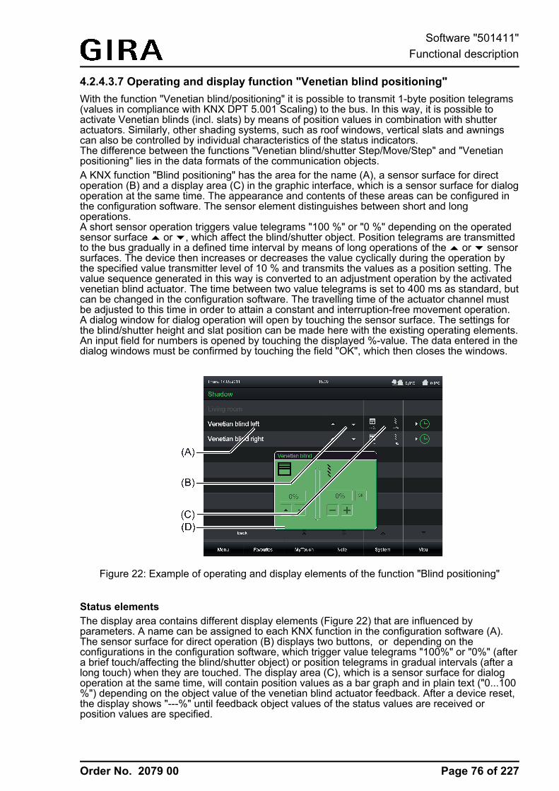
Order No. 2079 00
4.2.4.3.7 Operating and display function "Venetian blind positioning"With the function "Venetian blind/positioning" it is possible to transmit 1-byte position telegrams(values in compliance with KNX DPT 5.001 Scaling) to the bus. In this way, it is possible toactivate Venetian blinds (incl. slats) by means of position values in combination with shutteractuators. Similarly, other shading systems, such as roof windows, vertical slats and awningscan also be controlled by individual characteristics of the status indicators.The difference between the functions "Venetian blind/shutter Step/Move/Step" and "Venetianpositioning" lies in the data formats of the communication objects.A KNX function "Blind positioning" has the area for the name (A), a sensor surface for directoperation (B) and a display area (C) in the graphic interface, which is a sensor surface for dialogoperation at the same time. The appearance and contents of these areas can be configured inthe configuration software. The sensor element distinguishes between short and longoperations.A short sensor operation triggers value telegrams "100 %" or "0 %" depending on the operatedsensor surface ¬ or ¯, which affect the blind/shutter object. Position telegrams are transmittedto the bus gradually in a defined time interval by means of long operations of the ¬ or ¯ sensorsurfaces. The device then increases or decreases the value cyclically during the operation bythe specified value transmitter level of 10 % and transmits the values as a position setting. Thevalue sequence generated in this way is converted to an adjustment operation by the activatedvenetian blind actuator. The time between two value telegrams is set to 400 ms as standard, butcan be changed in the configuration software. The travelling time of the actuator channel mustbe adjusted to this time in order to attain a constant and interruption-free movement operation.A dialog window for dialog operation will open by touching the sensor surface. The settings forthe blind/shutter height and slat position can be made here with the existing operating elements.An input field for numbers is opened by touching the displayed %-value. The data entered in thedialog windows must be confirmed by touching the field "OK", which then closes the windows.
Figure 22: Example of operating and display elements of the function "Blind positioning"
Status elementsThe display area contains different display elements (Figure 22) that are influenced byparameters. A name can be assigned to each KNX function in the configuration software (A).The sensor surface for direct operation (B) displays two buttons, or depending on theconfigurations in the configuration software, which trigger value telegrams "100%" or "0%" (aftera brief touch/affecting the blind/shutter object) or position telegrams in gradual intervals (after along touch) when they are touched. The display area (C), which is a sensor surface for dialogoperation at the same time, will contain position values as a bar graph and in plain text ("0...100%") depending on the object value of the venetian blind actuator feedback. After a device reset,the display shows "---%" until feedback object values of the status values are received orposition values are specified.
Page 76 of 227
Software "501411"Functional description

Order No. 2079 00
A dialog window (D) for dialog operation where the position value can be entered directly willopen by touching the sensor surface.
Objects
The KNX function "Venetian blind positioning" has up to 4 KNX communication objects...
- "Venetian blind position" (1-bit transmitting and optional receiving):Value telegrams for the blind/shutter height setting are transmitted to the bus via this objectafter pressing the sensor elements. This can cause a blind position object (e.g. "PositionVenetian blind", "Position rolling shutter/awning", "Position venting louver"...) of a blind orshutter actuator to be activated.If the parameter "Use feedback object" is not selected, the position value received via thisobject also influences the status indications. This is advisable, for instance, if the activatedKNX Venetian blind or shutter actuator does not have any separate feedback objects forthe blind/shutter position.
- "Slat position" (1-bit transmitting and optional receiving):Value telegrams for the slat position setting are transmitted to the bus via this object afterpressing the sensor elements. This can cause a slat position object of a shutter actuator tobe activated.If the parameter "Use feedback object" is not selected, the position value received via thisobject also influences the status indications. This is advisable, for instance, if the activatedKNX Venetian blind actuator does not have any separate feedback objects for the slatposition.
- "Feedback blind/shutter position" (1-byte receiving):Through this object the device can receive a position feedback for the blind/shutter heightthat a shutter actuator transmits, for example. The status value as well as the bar graph forthe blind/shutter height visualisation are influenced as a result. The feedback of the positionvalue must be transmitted by the "actively transmitting" actuator.If the activated KNX Venetian blind or shutter actuator does not have a separate statusfeedback for the blind/shutter height, the parameter "Use feedback object" can bedeselected whereby the blind/shutter status indications are activated via the object"Venetian blind position".
- "Slat position feedback" (1-byte receiving):Through this object the device can receive a position feedback for the slat position that aVenetian blind actuator transmits, for example. The status value as well as the bar graphfor the slat visualisation are influenced as a result. The feedback of the position value mustalso be transmitted here by the "actively transmitting" actuator.If the activated KNX Venetian blind actuator does not have a separate status feedback forthe slat position, the parameter "Use feedback object" can be deselected whereby the slatstatus indications are activated via the object "Slat position".
i The objects interpret values to be sent or received on the basis of the KNX data point type5.001 (Scaling). The decimal data values 0...255 are evaluated as percentages 0...100 %.
Page 77 of 227
Software "501411"Functional description
Order No. 2079 00
i During an operation, the values of the objects "Venetian blind position feedback" and "Slatposition feedback" are not evaluated. With a long press of the sensor elements or acontinuous value adjustment can take place on the bus. During this value adjustment, allstatus elements of the function element are updated continuously by value simulation. Thedisplay elements first react again to the feedback object value of the Venetian blind orshutter actuator after a short waiting time once the operation has been completed.
Slat correctionThe KNX function of the "Venetian blind/ positioning" supports the supplementary function of theslat correction. Many KNX shutter actuators track the slat position when the shutter heightchanges due to a position setting. These actuators also reposition the slats when the blindposition is preset to 0%, i.e. to the upper end position. This repositioning of the slats is oftenundesirable in the upper end position of the Venetian blind since the returned blind height alsochanges again due to the movement of the slats (position of blind unequal 0%). To prevent theslat from being repositioned in the upper blind end position, the automatic slat correction can beactivated in the KNX function "Venetian blind/ positioning". It can be activated by parameter inthe configuration software.If the slat correction has been activated, the device always transmits a slat position of 0% for ablind height presetting of 0%. As a result, the slat is not repositioned when the upper endposition is reached since this is already in the 0% position after the upward movement. It doesnot matter which operation performs the 0% presetting. Consequently, the slat correction willonly function after short or long operations of the sensor surfaces or when changing the slider ifa 0% blind position is set.The automatic slat correction does not apply to position presettings for the blind within the range1...100%. In such cases, the device only transmits slat positions when a slat operation isperformed using the sensor surfaces or the slider.
Page 78 of 227
Software "501411"Functional description
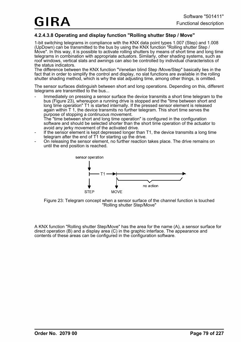
Order No. 2079 00
4.2.4.3.8 Operating and display function "Rolling shutter Step / Move"1-bit switching telegrams in compliance with the KNX data point types 1.007 (Step) and 1.008(UpDown) can be transmitted to the bus by using the KNX function "Rolling shutter Step /Move". In this way, it is possible to activate rolling shutters by means of short time and long timetelegrams in combination with appropriate actuators. Similarly, other shading systems, such asroof windows, vertical slats and awnings can also be controlled by individual characteristics ofthe status indicators.The difference between the KNX function "Venetian blind Step /Move/Step" basically lies in thefact that in order to simplify the control and display, no slat functions are available in the rollingshutter shading method, which is why the slat adjusting time, among other things, is omitted.
The sensor surfaces distinguish between short and long operations. Depending on this, differenttelegrams are transmitted to the bus...- Immediately on pressing a sensor surface the device transmits a short time telegram to the
bus (Figure 23), whereupon a running drive is stopped and the "time between short andlong time operation" T1 is started internally. If the pressed sensor element is releasedagain within T 1, the device transmits no further telegram. This short time serves thepurpose of stopping a continuous movement.The "time between short and long time operation" is configured in the configurationsoftware and should be selected shorter than the short time operation of the actuator toavoid any jerky movement of the activated drive.
- If the sensor element is kept depressed longer than T1, the device transmits a long timetelegram after the end of T1 for starting up the drive.
- On releasing the sensor element, no further reaction takes place. The drive remains onuntil the end position is reached.
Figure 23: Telegram concept when a sensor surface of the channel function is touched"Rolling shutter Step/Move"
A KNX function "Rolling shutter Step/Move" has the area for the name (A), a sensor surface fordirect operation (B) and a display area (C) in the graphic interface. The appearance andcontents of these areas can be configured in the configuration software.
Page 79 of 227
Software "501411"Functional description
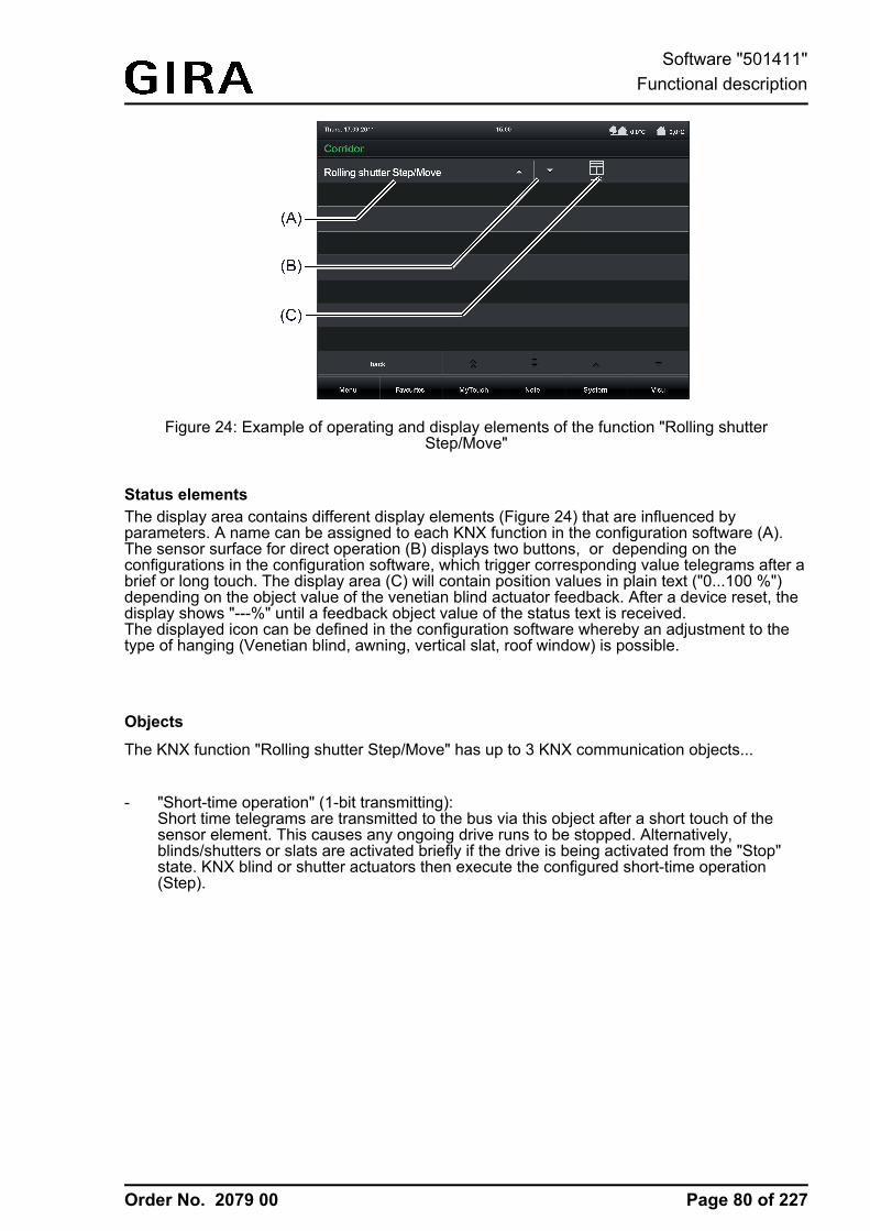
Order No. 2079 00
Figure 24: Example of operating and display elements of the function "Rolling shutterStep/Move"
Status elementsThe display area contains different display elements (Figure 24) that are influenced byparameters. A name can be assigned to each KNX function in the configuration software (A).The sensor surface for direct operation (B) displays two buttons, or depending on theconfigurations in the configuration software, which trigger corresponding value telegrams after abrief or long touch. The display area (C) will contain position values in plain text ("0...100 %")depending on the object value of the venetian blind actuator feedback. After a device reset, thedisplay shows "---%" until a feedback object value of the status text is received.The displayed icon can be defined in the configuration software whereby an adjustment to thetype of hanging (Venetian blind, awning, vertical slat, roof window) is possible.
Objects
The KNX function "Rolling shutter Step/Move" has up to 3 KNX communication objects...
- "Short-time operation" (1-bit transmitting):Short time telegrams are transmitted to the bus via this object after a short touch of thesensor element. This causes any ongoing drive runs to be stopped. Alternatively,blinds/shutters or slats are activated briefly if the drive is being activated from the "Stop"state. KNX blind or shutter actuators then execute the configured short-time operation(Step).
Page 80 of 227
Software "501411"Functional description
Order No. 2079 00
- "Long-time operation" (1-bit transmitting):Long time telegrams (up, down) are transmitted to the bus via this object after a long pressof the sensor element. This enables activated blinds/shutters of shading systems to becontrolled until the end positions. KNX blind or shutter actuators additionally execute theconfigured long-time operation (Move).A short time telegram (see object "Short-time object") can interrupt ongoing drive runs ofthe long time operation (Stop) thereby enabling a blind/shutter to be stopped at any desiredpoint.
- "Feedback blind/shutter position" (1-byte receiving):Through this object the device can receive a position feedback for the blind/shutter heightthat a shutter actuator transmits, for example. The status value, status icon and also thebar graph for the blind/shutter height visualisation are influenced as a result. The feedbackof the position value must be transmitted by the "actively transmitting" actuator.If the activated KNX Venetian blind or shutter actuator does not have a feedback for theblind/shutter position, the parameter "Use feedback object" can be deselected whereby allthe status indications are then no longer available either, however.
i The object "Rolling shutter feedback" interprets received values on the basis of the KNXdata point type 5.001 (Scaling). The decimal data values 0...255 are evaluated aspercentages 0...100 % and displayed in the device display.
i Since Venetian blind or shutter actuators normally transmit position values as feedback, theactivated motors stop when driver runs have been completed. For this reason, statusindications of the function element concerned do not normally change during a press of thesensor surface, but only when the buttons are released and the drive runs are stopped. Bycontrast, a displayed status value can already change even during an operation if the driveis already in the end position or cannot pass through the entire position range due todisabling functions.
Page 81 of 227
Software "501411"Functional description
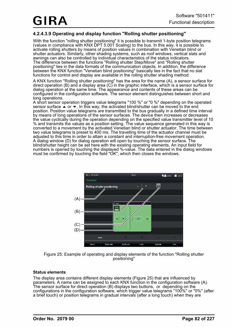
Order No. 2079 00
4.2.4.3.9 Operating and display function "Rolling shutter positioning"With the function "rolling shutter positioning" it is possible to transmit 1-byte position telegrams(values in compliance with KNX DPT 5.001 Scaling) to the bus. In this way, it is possible toactivate rolling shutters by means of position values in combination with Venetian blind orshutter actuators. Similarly, other shading systems, such as roof windows, vertical slats andawnings can also be controlled by individual characteristics of the status indicators.The difference between the functions "Rolling shutter Step/Move" and "Rolling shutterpositioning" lies in the data formats of the communication objects. In addition, the differencebetween the KNX function "Venetian blind positioning" basically lies in the fact that no slatfunctions for control and display are available in the rolling shutter shading method.A KNX function "Rolling shutter positioning" has the area for the name (A), a sensor surface fordirect operation (B) and a display area (C) in the graphic interface, which is a sensor surface fordialog operation at the same time. The appearance and contents of these areas can beconfigured in the configuration software. The sensor element distinguishes between short andlong operations.A short sensor operation triggers value telegrams "100 %" or "0 %" depending on the operatedsensor surface ¬ or ¯. In this way, the activated blind/shutter can be moved to the endposition. Position value telegrams are transmitted to the bus gradually in a defined time intervalby means of long operations of the sensor surfaces. The device then increases or decreasesthe value cyclically during the operation depending on the specified value transmitter level of 10% and transmits the values as a position setting. The value sequence generated in this way isconverted to a movement by the activated Venetian blind or shutter actuator. The time betweentwo value telegrams is preset to 400 ms. The travelling time of the actuator channel must beadjusted to this time in order to attain a constant and interruption-free movement operation.A dialog window (D) for dialog operation will open by touching the sensor surface. Theblind/shutter height can be set here with the existing operating elements. An input field fornumbers is opened by touching the displayed %-value. The data entered in the dialog windowsmust be confirmed by touching the field "OK", which then closes the windows.
Figure 25: Example of operating and display elements of the function "Rolling shutterpositioning"
Status elementsThe display area contains different display elements (Figure 25) that are influenced byparameters. A name can be assigned to each KNX function in the configuration software (A).The sensor surface for direct operation (B) displays two buttons, or depending on theconfigurations in the configuration software, which trigger value telegrams "100%" or "0%" (aftera brief touch) or position telegrams in gradual intervals (after a long touch) when they are
Page 82 of 227
Software "501411"Functional description
Order No. 2079 00
touched. The display area (C), which is a sensor surface for dialog operation at the same time,will display position values in plain text ("0...100 %") depending on the object value of theshutter actuator feedback. After a device reset, the display shows "---%" until feedback objectvalues of the status values are received or position values are specified.A dialog window (D) for dialog operation where the position value can be entered directly willopen by touching the sensor surface.
Objects
The KNX function "Rolling shutter positioning" has up to 2 KNX communication objects...
- "blind/shutter position" (1-byte transmitting and optional receiving):Value telegrams for the blind/shutter height setting are transmitted to the bus via this objectafter pressing the sensor elements. This can cause a blind position object (e.g. "Positionrolling shutter", "Position rolling shutter/awning", "Position venting louver"...) of a blind orshutter actuator to be activated.If the parameter "Use feedback object" is not selected, the position value received via thisobject also influences the status indications. This is advisable, for instance, if the activatedKNX Venetian blind or shutter actuator does not have any separate feedback objects forthe blind/shutter position.
- "Feedback blind/shutter position" (1-byte receiving):Through this object the device can receive a position feedback for the blind/shutter heightthat a shutter actuator transmits, for example. The status value, status icon and also thebar graph for the blind/shutter height visualisation are influenced as a result. The feedbackof the position value must be transmitted by the "actively transmitting" actuator.If the activated KNX Venetian blind or shutter actuator does not have a separate statusfeedback for the blind/shutter height, the parameter "Use feedback object" can bedeselected whereby the blind/shutter status indications are activated via the object "Rollingshutter position".
i The objects interpret values to be sent or received on the basis of the KNX data point type5.001 (Scaling). The decimal data values 0...255 are evaluated as percentages 0...100 %.
i During an operation, the value of the object "Rolling shutter position feedback" is notevaluated. With a long press of the sensor elements / a continuous value adjustment cantake place on the bus. During this value adjustment, all status elements of the functionelement are updated continuously by value simulation. The display elements first reactagain to the feedback object value of the Venetian blind or shutter actuator after a shortwaiting time once the operation has been completed.
Page 83 of 227
Software "501411"Functional description
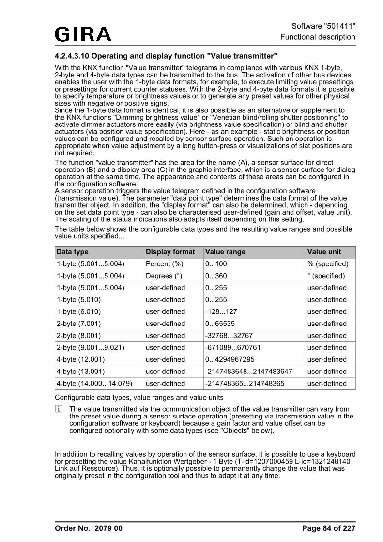
Order No. 2079 00
4.2.4.3.10 Operating and display function "Value transmitter"With the KNX function "Value transmitter" telegrams in compliance with various KNX 1-byte,2-byte and 4-byte data types can be transmitted to the bus. The activation of other bus devicesenables the user with the 1-byte data formats, for example, to execute limiting value presettingsor presettings for current counter statuses. With the 2-byte and 4-byte data formats it is possibleto specify temperature or brightness values or to generate any preset values for other physicalsizes with negative or positive signs.Since the 1-byte data format is identical, it is also possible as an alternative or supplement tothe KNX functions "Dimming brightness value" or "Venetian blind/rolling shutter positioning" toactivate dimmer actuators more easily (via brightness value specification) or blind and shutteractuators (via position value specification). Here - as an example - static brightness or positionvalues can be configured and recalled by sensor surface operation. Such an operation isappropriate when value adjustment by a long button-press or visualizations of slat positions arenot required.The function "value transmitter" has the area for the name (A), a sensor surface for directoperation (B) and a display area (C) in the graphic interface, which is a sensor surface for dialogoperation at the same time. The appearance and contents of these areas can be configured inthe configuration software.A sensor operation triggers the value telegram defined in the configuration software(transmission value). The parameter "data point type" determines the data format of the valuetransmitter object. In addition, the "display format" can also be determined, which - dependingon the set data point type - can also be characterised user-defined (gain and offset, value unit).The scaling of the status indications also adapts itself depending on this setting.The table below shows the configurable data types and the resulting value ranges and possiblevalue units specified...
Data type Display format Value range Value unit1-byte (5.001...5.004) Percent (%) 0...100 % (specified)
1-byte (5.001...5.004) Degrees (°) 0...360 ° (specified)
1-byte (5.001...5.004) user-defined 0...255 user-defined
1-byte (5.010) user-defined 0...255 user-defined
1-byte (6.010) user-defined -128...127 user-defined
2-byte (7.001) user-defined 0...65535 user-defined
2-byte (8.001) user-defined -32768...32767 user-defined
2-byte (9.001...9.021) user-defined -671089...670761 user-defined
4-byte (12.001) user-defined 0...4294967295 user-defined
4-byte (13.001) user-defined -2147483648...2147483647 user-defined
4-byte (14.000...14.079) user-defined -214748365...214748365 user-defined
Configurable data types, value ranges and value unitsi The value transmitted via the communication object of the value transmitter can vary from
the preset value during a sensor surface operation (presetting via transmission value in theconfiguration software or keyboard) because a gain factor and value offset can beconfigured optionally with some data types (see "Objects" below).
In addition to recalling values by operation of the sensor surface, it is possible to use a keyboardfor presetting the value Kanalfunktion Wertgeber - 1 Byte (T-id=1207000459 L-id=1321248140Link auf Ressource). Thus, it is optionally possible to permanently change the value that wasoriginally preset in the configuration tool and thus to adapt it at any time.
Page 84 of 227
Software "501411"Functional description
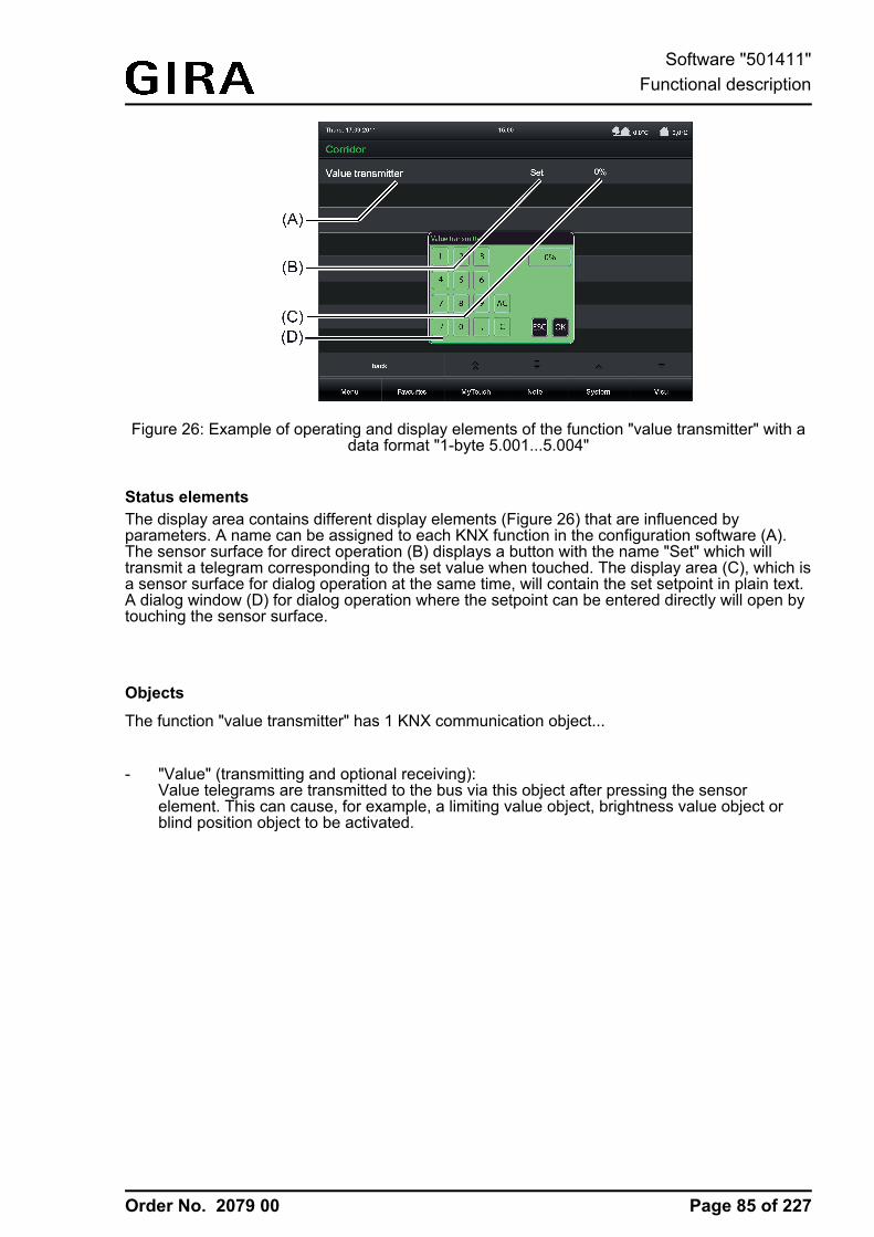
Order No. 2079 00
Figure 26: Example of operating and display elements of the function "value transmitter" with adata format "1-byte 5.001...5.004"
Status elementsThe display area contains different display elements (Figure 26) that are influenced byparameters. A name can be assigned to each KNX function in the configuration software (A).The sensor surface for direct operation (B) displays a button with the name "Set" which willtransmit a telegram corresponding to the set value when touched. The display area (C), which isa sensor surface for dialog operation at the same time, will contain the set setpoint in plain text.A dialog window (D) for dialog operation where the setpoint can be entered directly will open bytouching the sensor surface.
Objects
The function "value transmitter" has 1 KNX communication object...
- "Value" (transmitting and optional receiving):Value telegrams are transmitted to the bus via this object after pressing the sensorelement. This can cause, for example, a limiting value object, brightness value object orblind position object to be activated.
Page 85 of 227
Software "501411"Functional description
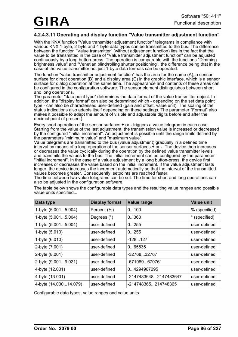
Order No. 2079 00
4.2.4.3.11 Operating and display function "Value transmitter adjustment function"With the KNX function "Value transmitter adjustment function" telegrams in compliance withvarious KNX 1-byte, 2-byte and 4-byte data types can be transmitted to the bus. The differencebetween the function "Value transmitter" (without adjustment function) lies in the fact that thevalue to be transmitted in the case of "Value transmitter adjustment function" can be adjustedcontinuously by a long button-press. The operation is comparable with the functions "Dimmingbrightness value" and "Venetian blind/rolling shutter positioning", the difference being that in thecase of the value transmitter not just 1-byte data formats can be operated.The function "value transmitter adjustment function" has the area for the name (A), a sensorsurface for direct operation (B) and a display area (C) in the graphic interface, which is a sensorsurface for dialog operation at the same time. The appearance and contents of these areas canbe configured in the configuration software. The sensor element distinguishes between shortand long operations.The parameter "data point type" determines the data format of the value transmitter object. Inaddition, the "display format" can also be determined which - depending on the set data pointtype - can also be characterised user-defined (gain and offset, value unit). The scaling of thestatus indications also adapts itself depending on these settings. The parameter "Format" alsomakes it possible to adapt the amount of visible and adjustable digits before and after thedecimal point (if present).Every short operation of the sensor surfaces + or - triggers a value telegram in each case.Starting from the value of the last adjustment, the transmission value is increased or decreasedby the configured "initial increment". An adjustment is possible until the range limits defined bythe parameters "minimum value" and "maximum value".Value telegrams are transmitted to the bus (value adjustment) gradually in a defined timeinterval by means of a long operation of the sensor surfaces + or -. The device then increasesor decreases the value cyclically during the operation by the defined value transmitter levelsand transmits the values to the bus. The initial increment can be configured by the parameter"initial increment". In the case of a value adjustment by a long button-press, the device firstincreases or decreases the value based on the initial increment. If the value adjustment lastslonger, the device increases the increment automatically so that the interval of the transmittedvalues becomes greater. Consequently, setpoints are reached faster.The time between two value telegrams can be set. The time for short and long operations canalso be adjusted in the configuration software.The table below shows the configurable data types and the resulting value ranges and possiblevalue units specified...
Data type Display format Value range Value unit1-byte (5.001...5.004) Percent (%) 0...100 % (specified)
1-byte (5.001...5.004) Degrees (°) 0...360 ° (specified)
1-byte (5.001...5.004) user-defined 0...255 user-defined
1-byte (5.010) user-defined 0...255 user-defined
1-byte (6.010) user-defined -128...127 user-defined
2-byte (7.001) user-defined 0...65535 user-defined
2-byte (8.001) user-defined -32768...32767 user-defined
2-byte (9.001...9.021) user-defined -671089...670761 user-defined
4-byte (12.001) user-defined 0...4294967295 user-defined
4-byte (13.001) user-defined -2147483648...2147483647 user-defined
4-byte (14.000...14.079) user-defined -214748365...214748365 user-defined
Configurable data types, value ranges and value units
Page 86 of 227
Software "501411"Functional description
Order No. 2079 00
i The value transmitted via the communication object of the value transmitter can vary fromthe preset value during a sensor surface operation because a gain factor and value offsetcan be configured optionally with some data types (see "Objects" below).
In addition to recalling values by operation of the sensor surface, it is possible to use a keyboardfor presetting the value Kanalfunktion Wertgeber Verstellfunktion - 1 Byte (T-id=1232581771 L-id=1321257356 Link auf Ressource). Thus, it is optionally possible to change the transmissionvalue regardless of the value transmitter levels.
Figure 27: Example of operating and display elements of the function "value transmitteradjustment function" with a data format "1-byte 5.001...5.004"
Status elementsThe display area contains different display elements (Figure 27) that are influenced byparameters. A name can be assigned to each KNX function in the configuration software (A).The sensor surface for direct operation (B) displays the sensor surfaces + or -, which willtransmit a telegram corresponding to the set value when touched. The display area (C), which isa sensor surface for dialog operation at the same time, will contain a graphic setpoint display.A dialog window (D) for dialog operation where the setpoint can be entered directly will open bytouching the sensor surface.
Page 87 of 227
Software "501411"Functional description
Order No. 2079 00
Objects
The KNX function "Value transmitter adjustment function" has up to 2 KNX communicationobjects...
- "Value" (transmitting and optional receiving):Value telegrams are transmitted to the bus via this object after pressing the sensorelement. This can cause, for example, a limiting value object, brightness value object orblind position object to be activated.
- "Feedback value" (receiving):Through this object the device can receive a value feedback that an activated actuatortransmits, for example. The status value for the value visualization is influenced as a result.The feedback of the value must be transmitted by the "actively transmitting" actuator.If the activated KNX actuator does not have a separate status feedback, the parameter"Use value feedback object" can be deselected whereby the status indications areactivated via the object "Value".
i The status elements of the function are influenced by the objects "Value" or "Feedbackvalue". In addition, a value recall by sensor operation or by entry via keyboard alsoinfluences the status elements. During a value recall, the status elements are updatedaccording to the recalled value regardless of the current feedback value. The displayelements first react again to the returned object value from the addressed device after avalue recall by operation. As a result, this may cause a leap in value in the status indicationwhen returned values vary from the preset value.
Page 88 of 227
Software "501411"Functional description
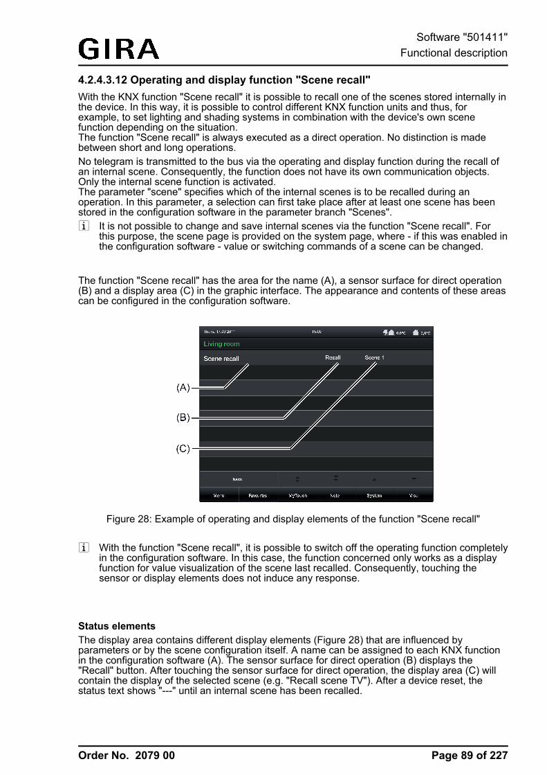
Order No. 2079 00
4.2.4.3.12 Operating and display function "Scene recall"With the KNX function "Scene recall" it is possible to recall one of the scenes stored internally inthe device. In this way, it is possible to control different KNX function units and thus, forexample, to set lighting and shading systems in combination with the device's own scenefunction depending on the situation.The function "Scene recall" is always executed as a direct operation. No distinction is madebetween short and long operations.No telegram is transmitted to the bus via the operating and display function during the recall ofan internal scene. Consequently, the function does not have its own communication objects.Only the internal scene function is activated.The parameter "scene" specifies which of the internal scenes is to be recalled during anoperation. In this parameter, a selection can first take place after at least one scene has beenstored in the configuration software in the parameter branch "Scenes".i It is not possible to change and save internal scenes via the function "Scene recall". For
this purpose, the scene page is provided on the system page, where - if this was enabled inthe configuration software - value or switching commands of a scene can be changed.
The function "Scene recall" has the area for the name (A), a sensor surface for direct operation(B) and a display area (C) in the graphic interface. The appearance and contents of these areascan be configured in the configuration software.
Figure 28: Example of operating and display elements of the function "Scene recall"
i With the function "Scene recall", it is possible to switch off the operating function completelyin the configuration software. In this case, the function concerned only works as a displayfunction for value visualization of the scene last recalled. Consequently, touching thesensor or display elements does not induce any response.
Status elementsThe display area contains different display elements (Figure 28) that are influenced byparameters or by the scene configuration itself. A name can be assigned to each KNX functionin the configuration software (A). The sensor surface for direct operation (B) displays the"Recall" button. After touching the sensor surface for direct operation, the display area (C) willcontain the display of the selected scene (e.g. "Recall scene TV"). After a device reset, thestatus text shows "---" until an internal scene has been recalled.
Page 89 of 227
Software "501411"Functional description
Order No. 2079 00
Objects No telegram is transmitted to the bus via the operating and display function during the recall ofan internal scene using the function "Scene recall". Consequently, the function does not have itsown communication objects. Only the internal scene function is activated.
Page 90 of 227
Software "501411"Functional description
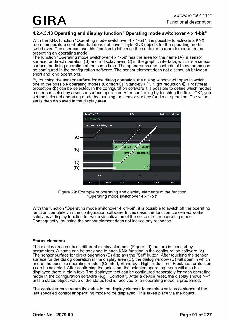
Order No. 2079 00
4.2.4.3.13 Operating and display function "Operating mode switchover 4 x 1-bit"With the KNX function "Operating mode switchover 4 x 1-bit " it is possible to activate a KNXroom temperature controller that does not have 1-byte KNX objects for the operating modeswitchover. The user can use this function to influence the control of a room temperature bypresetting an operating mode.The function "Operating mode switchover 4 x 1-bit" has the area for the name (A), a sensorsurface for direct operation (B) and a display area (C) in the graphic interface, which is a sensorsurface for dialog operation at the same time. The appearance and contents of these areas canbe configured in the configuration software. The sensor element does not distinguish betweenshort and long operations.By touching the sensor surface for the dialog operation, the dialog window will open in whichone of the possible operating modes (Comfort0, Stand-by 1, Night reduction 2, Frost/heatprotection ¾) can be selected. In the configuration software it is possible to define which modesa user can select by a sensor surface operation. After confirming by touching the field "OK", youset the selected operating mode by touching the sensor surface for direct operation. The valueset is then displayed in the display area.
Figure 29: Example of operating and display elements of the function"Operating mode switchover 4 x 1-bit"
With the function "Operating mode switchover 4 x 1-bit", it is possible to switch off the operatingfunction completely in the configuration software. In this case, the function concerned workssolely as a display function for value visualization of the set controller operating mode.Consequently, touching the sensor element does not induce any response.
Status elementsThe display area contains different display elements (Figure 29) that are influenced byparameters. A name can be assigned to each KNX function in the configuration software (A).The sensor surface for direct operation (B) displays the "Set" button. After touching the sensorsurface for the dialog operation in the display area (C), the dialog window (D) will open in whichone of the possible operating modes (Comfort, Stand-by , Night reduction , Frost/heat protection) can be selected. After confirming the selection, the selected operating mode will also bedisplayed there in plain text. The displayed text can be configured separately for each operatingmode in the configuration software (e.g. "Comfort"). After a device reset, the display shows "---"until a status object value of the status text is received or an operating mode is predefined.
The controller must return its status to the display element to enable a valid acceptance of thelast specified controller operating mode to be displayed. This takes place via the object
Page 91 of 227
Software "501411"Functional description
Order No. 2079 00
"Feedback status" (see page 92-93). If the status feedback of the controller is not used(parameter "Use feedback object" is deselected), the display element automatically assumesafter each presetting by the user that the operating mode last specified by the controller wasalso accepted as valid by the controller.With the function "Operating mode switchover 4 x 1-bit", it is possible to switch off the operatingfunction completely in the configuration software. In this case, the function concerned workssolely as a display function for value visualization of the set controller operating mode.Consequently, touching the sensor element does not induce any response.
Objects
The KNX function "Operating mode switchover 4 x 1-bit" has up to 5 KNX communicationobjects...
- "Comfort mode" (1-bit transmitting and optional receiving):A "1"-telegram is transmitted to the bus via this object after pressing the sensor elementwhen the comfort mode is activated. The object for the comfort mode of the roomtemperature controller is activated as a result.If the parameter "Use feedback object" is not selected, the object value received via thisobject also influences the status indications. This is advisable, for instance, if the activatedKNX room temperature controller has a separate 1-byte status feedback object.
- "Standby" (1-bit transmitting and optional receiving):A "1"-telegram is transmitted to the bus via this object after pressing the sensor elementwhen the standby operating mode is activated. The object for the standby operation of theroom temperature controller is activated as a result.If the parameter "Use feedback object" is not selected, the object value received via thisobject also influences the status indications. This is advisable, for instance, if the activatedKNX room temperature controller has a separate 1-byte status feedback object.
- "Night reduction" (1-bit transmitting and optional receiving):A "1"-telegram is transmitted to the bus via this object after pressing the sensor elementwhen the night operating mode is activated. The object for the night operation of the roomtemperature controller is activated as a result.If the parameter "Use feedback object" is not selected, the object value received via thisobject also influences the status indications. This is advisable, for instance, if the activatedKNX room temperature controller has a separate 1-byte status feedback object.
Page 92 of 227
Software "501411"Functional description
Order No. 2079 00
- "Frost/heat protection" (1-bit transmitting and optional receiving):A "1"-telegram is transmitted to the bus via this object after pressing the sensor elementwhen the frost/heat protection mode is activated. The object for the frost/heat protectionmode of the room temperature controller is activated as a result.If the parameter "Use feedback object" is not selected, the object value received via thisobject also influences the status indications. This is advisable, for instance, if the activatedKNX room temperature controller has a separate 1-byte status feedback object.
- "Feedback status" (1-byte receiving):This object is only visible when the parameter "Use feedback object" is activated. Throughthis object the device can then receive a KNX compliant 1-byte status feedback of theactivated KNX room temperature controller. This influences the status text and status iconthat are displayed in the display area of the function element.If the activated KNX room temperature controller does not have a separate 1-byte statusfeedback, the parameter "Use feedback object" can be deselected whereby the statusindications are activated via the four 1-bit objects. The display element evaluates thepriorities of the four 1-bit objects automatically in this case and updates the statusindications accordingly.
i With the function "Operating mode switchover 4 x 1-bit" it is always necessary to occupythe four 1-bit communication objects "Comfort mode", "Standby", "Night reduction" and"Frost/heat protection" with separate group addresses and link them to objects of theactivated room temperature controller with the same function!If the activated room temperature controller enables a KNX-compliant operating modeswitchover via 1-byte KNX objects, the function "Operating mode switchover KNX" shouldbe reverted to.
Page 93 of 227
Software "501411"Functional description
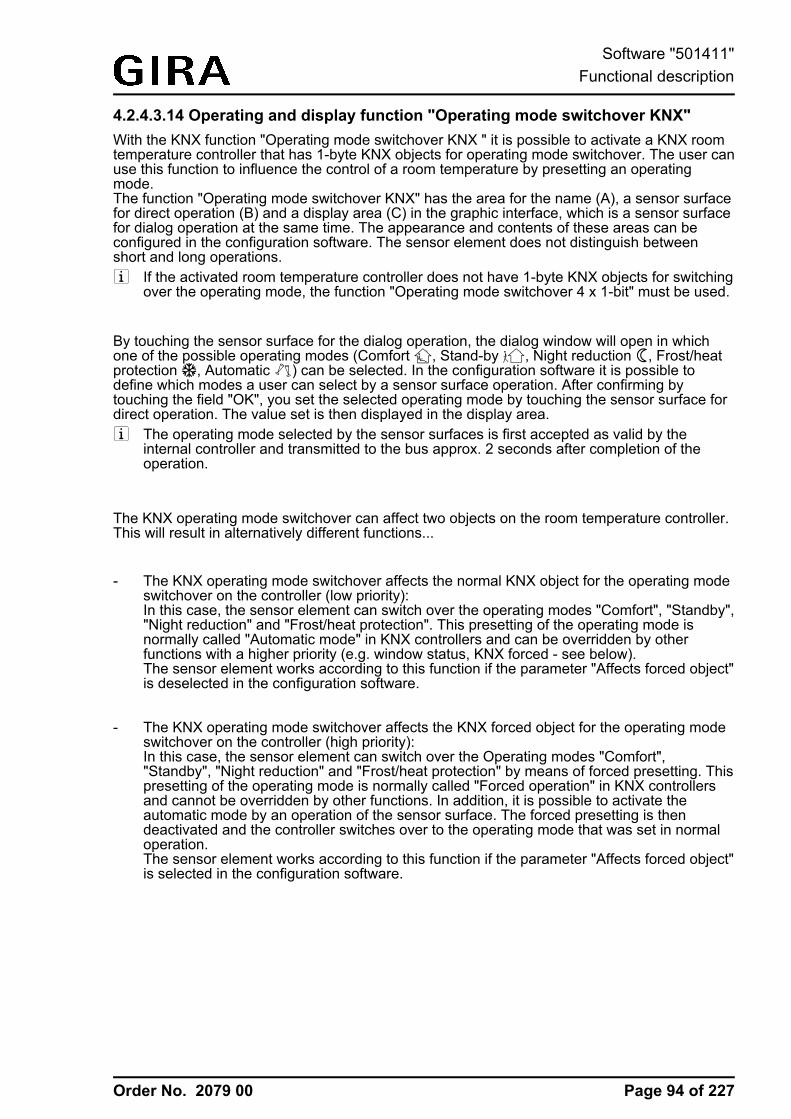
Order No. 2079 00
4.2.4.3.14 Operating and display function "Operating mode switchover KNX"With the KNX function "Operating mode switchover KNX " it is possible to activate a KNX roomtemperature controller that has 1-byte KNX objects for operating mode switchover. The user canuse this function to influence the control of a room temperature by presetting an operatingmode.The function "Operating mode switchover KNX" has the area for the name (A), a sensor surfacefor direct operation (B) and a display area (C) in the graphic interface, which is a sensor surfacefor dialog operation at the same time. The appearance and contents of these areas can beconfigured in the configuration software. The sensor element does not distinguish betweenshort and long operations.i If the activated room temperature controller does not have 1-byte KNX objects for switching
over the operating mode, the function "Operating mode switchover 4 x 1-bit" must be used.
By touching the sensor surface for the dialog operation, the dialog window will open in whichone of the possible operating modes (Comfort 0, Stand-by 1, Night reduction 2, Frost/heatprotection ¾, Automatic °) can be selected. In the configuration software it is possible todefine which modes a user can select by a sensor surface operation. After confirming bytouching the field "OK", you set the selected operating mode by touching the sensor surface fordirect operation. The value set is then displayed in the display area.i The operating mode selected by the sensor surfaces is first accepted as valid by the
internal controller and transmitted to the bus approx. 2 seconds after completion of theoperation.
The KNX operating mode switchover can affect two objects on the room temperature controller.This will result in alternatively different functions...
- The KNX operating mode switchover affects the normal KNX object for the operating modeswitchover on the controller (low priority):In this case, the sensor element can switch over the operating modes "Comfort", "Standby","Night reduction" and "Frost/heat protection". This presetting of the operating mode isnormally called "Automatic mode" in KNX controllers and can be overridden by otherfunctions with a higher priority (e.g. window status, KNX forced - see below).The sensor element works according to this function if the parameter "Affects forced object"is deselected in the configuration software.
- The KNX operating mode switchover affects the KNX forced object for the operating modeswitchover on the controller (high priority):In this case, the sensor element can switch over the Operating modes "Comfort","Standby", "Night reduction" and "Frost/heat protection" by means of forced presetting. Thispresetting of the operating mode is normally called "Forced operation" in KNX controllersand cannot be overridden by other functions. In addition, it is possible to activate theautomatic mode by an operation of the sensor surface. The forced presetting is thendeactivated and the controller switches over to the operating mode that was set in normaloperation.The sensor element works according to this function if the parameter "Affects forced object"is selected in the configuration software.
Page 94 of 227
Software "501411"Functional description
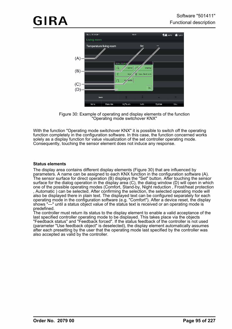
Order No. 2079 00
Figure 30: Example of operating and display elements of the function"Operating mode switchover KNX"
With the function "Operating mode switchover KNX" it is possible to switch off the operatingfunction completely in the configuration software. In this case, the function concerned workssolely as a display function for value visualization of the set controller operating mode.Consequently, touching the sensor element does not induce any response.
Status elementsThe display area contains different display elements (Figure 30) that are influenced byparameters. A name can be assigned to each KNX function in the configuration software (A).The sensor surface for direct operation (B) displays the "Set" button. After touching the sensorsurface for the dialog operation in the display area (C), the dialog window (D) will open in whichone of the possible operating modes (Comfort, Stand-by, Night reduction , Frost/heat protection, Automatic ) can be selected. After confirming the selection, the selected operating mode willalso be displayed there in plain text. The displayed text can be configured separately for eachoperating mode in the configuration software (e.g. "Comfort"). After a device reset, the displayshows "---" until a status object value of the status text is received or an operating mode ispredefined.The controller must return its status to the display element to enable a valid acceptance of thelast specified controller operating mode to be displayed. This takes place via the objects"Feedback status" and "Feedback forced". If the status feedback of the controller is not used(parameter "Use feedback object" is deselected), the display element automatically assumesafter each presetting by the user that the operating mode last specified by the controller wasalso accepted as valid by the controller.
Page 95 of 227
Software "501411"Functional description
Order No. 2079 00
Objects
The KNX function "Operating mode switchover KNX" has up to 3 KNX communication objects...
- "Operating mode KNX" (1-byte transmitting and optional receiving):A value telegram according to KNX DPT "20.102" is transmitted to the bus via this objectafter pressing the sensor element. The operating mode of the activated room temperaturecontroller is switched over as a result. Depending on the parameter "Affects forced object",either the normal KNX object for the operating mode switchover or the forced object of thecontroller is connected to this object.If the parameter "Use feedback object" is not selected, the object value received via thisobject also influences the status indications.
- "Feedback status" (1-byte receiving):This object is only visible when the parameter "Use feedback object" is activated. Throughthis object the device can then receive a KNX compliant 1-byte status feedback accordingto DPT "20.102" of the activated KNX room temperature controller. This influences thestatus text and status icon that are displayed in the display area of the function element.This object should only be used if the operating element affects a KNX forced object via theobject "operating mode KNX". The object "Feedback status" should then be linked to theKNX object for normal operating mode switchover of the controller. Otherwise, this objectremains unused. The feedback of the status must be transmitted by the room temperaturecontroller "actively transmitting" (set transmission flag if necessary).
- "Feedback forced" (1-byte receiving):This object is only visible when the parameter "Use feedback object" is activated. Throughthis object the device can then receive a KNX compliant 1-byte status feedback of therestraint of the activated KNX room temperature controller. This influences the status textthat could be displayed in the display area of the function element.This object should only be used if the operating element affects a KNX object for theoperating mode switchover via the object "operating mode KNX". The object "Feedbackforced" should then be linked to the KNX forced object of the controller. Otherwise, thisobject remains unused. The feedback of the forced status must be transmitted by the roomtemperature controller "actively transmitting" (set transmission flag if necessary).
i If the activated room temperature controller does not have 1-byte KNX objects for switchingover the operating mode, the function "Operating mode switchover 4 x 1-bit" must be used.
Page 96 of 227
Software "501411"Functional description
Order No. 2079 00
4.2.4.3.15 Operating and display function "Restraint"With the KNX function "Restraint" it is possible to activate KNX actuators (normally these areswitch actuators) at two different priority levels with just one operating element. By using thisfunction the user can also define switching states independent of a normal operation in order tointerlock the actuator channel in this way. Actuators that should be activated by the function"Restraint" must have a 1-bit communication object (normally "Switching") and 2-bit object(normally "Restraint"). The desired switching state ("1" or "0") is communicated to the actuatorin normal operation via the 1-bit object. The actuator can be interlocked in a defined switchingposition via the forced object. The switching state is then predefined directly by the forcedposition telegram. The first bit (bit 0) of the forced object specifies the switching state to beforced. The second bit (bit 1) of the object activates or deactivates the forced-position state (seetable below). The switching object is only evaluated in normal operation. The restraint is theninactive.
Bit 1 Bit 0 Function0 x Deactivated
1 0 Restrained OFF
1 1 Restrained ON
Coding of the 2-bit restraint
The function "Restraint" has a display element and the area for the name (A), a sensor surfacefor direct operation (B) and a display area (C) in the graphic interface, which is a sensor surfacefor dialog operation at the same time. The appearance and contents of these areas can beconfigured in the configuration software. The sensor element does not distinguish betweenshort and long operations.In the restraint "Deactivated" state, pressing the sensor surface for direct operation switches theobject directly to the "OFF" or "ON" states. The necessary telegrams are transmitted to the busvia both communication objects of the function (see page 98) for this purpose. The displayelement in the sensor surface for direct operation displays the switching state that should beproduced by the next touch, depending on the configurations in the configuration software.Appropriate colour markings and the changing of display texts is possible.In the "Restrained ON" state the restraint is switched on, in the "Restrained OFF" state therestraint is switched off. The pressing of the sensor surface for direct operation is disabled inboth cases. This is indicated by a darkened image of the sensor surface and a prohibit symbolthat is inserted there. The display element in the sensor surface for direct operation alsodisplays here the switching state that is not active.It is only possible to toggle between the "Restrained ON" and "Restrained OFF" states via thedialog window (D) which opens by touching the "wrench symbol".
Page 97 of 227
Software "501411"Functional description
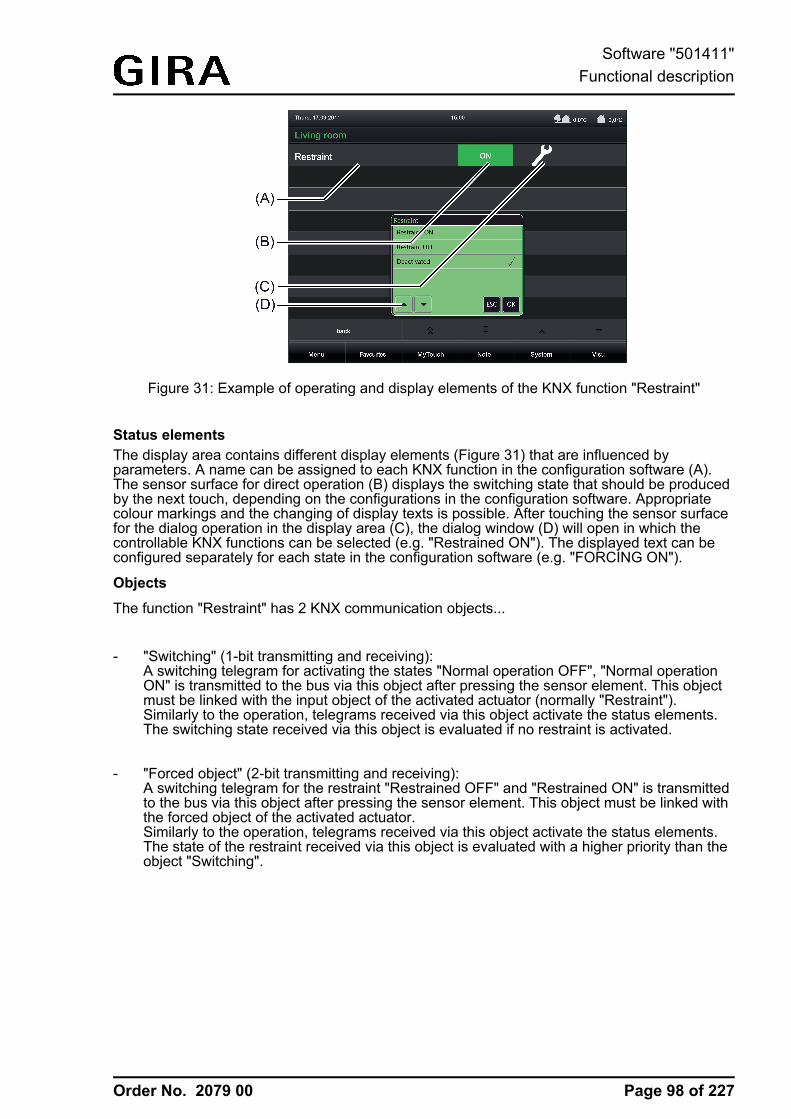
Order No. 2079 00
Figure 31: Example of operating and display elements of the KNX function "Restraint"
Status elementsThe display area contains different display elements (Figure 31) that are influenced byparameters. A name can be assigned to each KNX function in the configuration software (A).The sensor surface for direct operation (B) displays the switching state that should be producedby the next touch, depending on the configurations in the configuration software. Appropriatecolour markings and the changing of display texts is possible. After touching the sensor surfacefor the dialog operation in the display area (C), the dialog window (D) will open in which thecontrollable KNX functions can be selected (e.g. "Restrained ON"). The displayed text can beconfigured separately for each state in the configuration software (e.g. "FORCING ON").
Objects
The function "Restraint" has 2 KNX communication objects...
- "Switching" (1-bit transmitting and receiving):A switching telegram for activating the states "Normal operation OFF", "Normal operationON" is transmitted to the bus via this object after pressing the sensor element. This objectmust be linked with the input object of the activated actuator (normally "Restraint").Similarly to the operation, telegrams received via this object activate the status elements.The switching state received via this object is evaluated if no restraint is activated.
- "Forced object" (2-bit transmitting and receiving):A switching telegram for the restraint "Restrained OFF" and "Restrained ON" is transmittedto the bus via this object after pressing the sensor element. This object must be linked withthe forced object of the activated actuator.Similarly to the operation, telegrams received via this object activate the status elements.The state of the restraint received via this object is evaluated with a higher priority than theobject "Switching".
Page 98 of 227
Software "501411"Functional description
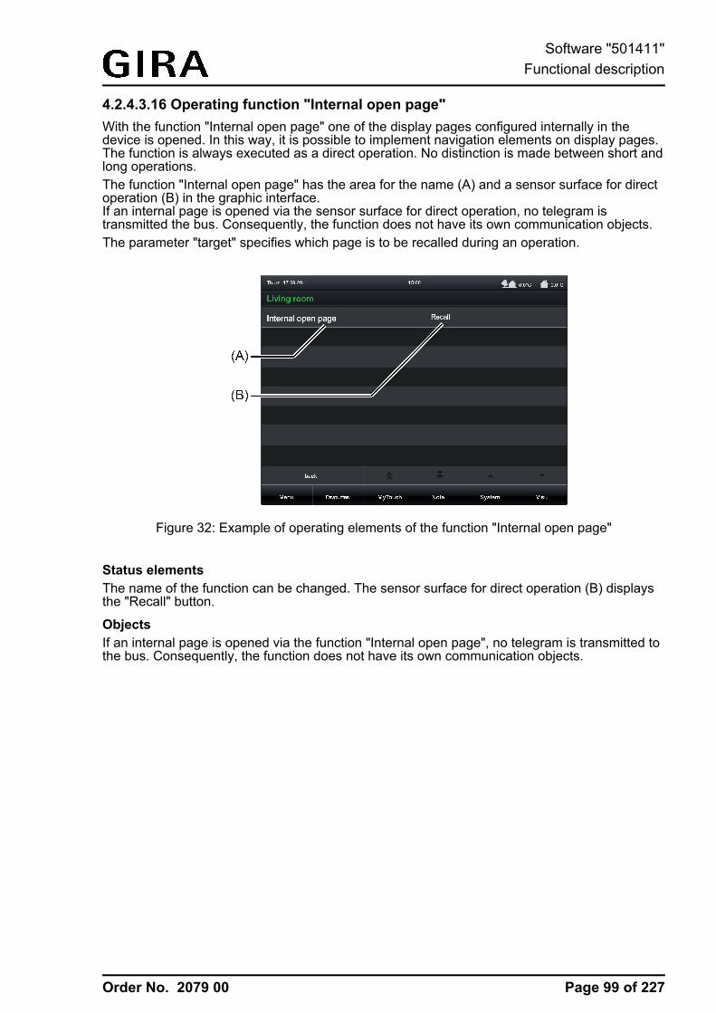
Order No. 2079 00
4.2.4.3.16 Operating function "Internal open page"With the function "Internal open page" one of the display pages configured internally in thedevice is opened. In this way, it is possible to implement navigation elements on display pages.The function is always executed as a direct operation. No distinction is made between short andlong operations.The function "Internal open page" has the area for the name (A) and a sensor surface for directoperation (B) in the graphic interface.If an internal page is opened via the sensor surface for direct operation, no telegram istransmitted the bus. Consequently, the function does not have its own communication objects.The parameter "target" specifies which page is to be recalled during an operation.
Figure 32: Example of operating elements of the function "Internal open page"
Status elementsThe name of the function can be changed. The sensor surface for direct operation (B) displaysthe "Recall" button.
ObjectsIf an internal page is opened via the function "Internal open page", no telegram is transmitted tothe bus. Consequently, the function does not have its own communication objects.
Page 99 of 227
Software "501411"Functional description
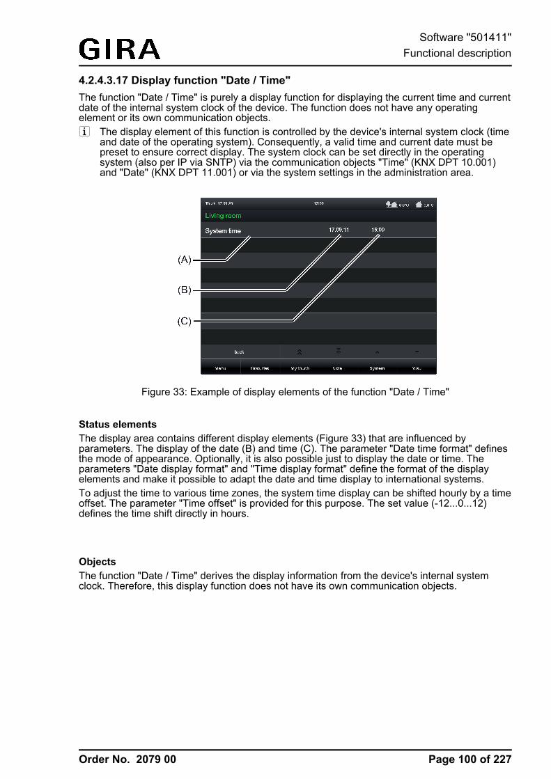
Order No. 2079 00
4.2.4.3.17 Display function "Date / Time"The function "Date / Time" is purely a display function for displaying the current time and currentdate of the internal system clock of the device. The function does not have any operatingelement or its own communication objects.i The display element of this function is controlled by the device's internal system clock (time
and date of the operating system). Consequently, a valid time and current date must bepreset to ensure correct display. The system clock can be set directly in the operatingsystem (also per IP via SNTP) via the communication objects "Time" (KNX DPT 10.001)and "Date" (KNX DPT 11.001) or via the system settings in the administration area.
Figure 33: Example of display elements of the function "Date / Time"
Status elementsThe display area contains different display elements (Figure 33) that are influenced byparameters. The display of the date (B) and time (C). The parameter "Date time format" definesthe mode of appearance. Optionally, it is also possible just to display the date or time. Theparameters "Date display format" and "Time display format" define the format of the displayelements and make it possible to adapt the date and time display to international systems.To adjust the time to various time zones, the system time display can be shifted hourly by a timeoffset. The parameter "Time offset" is provided for this purpose. The set value (-12...0...12)defines the time shift directly in hours.
ObjectsThe function "Date / Time" derives the display information from the device's internal systemclock. Therefore, this display function does not have its own communication objects.
Page 100 of 227
Software "501411"Functional description
Order No. 2079 00
4.2.4.3.18 Display function "KNX Time"The function "KNX Time" is purely a display function for displaying a time received via atelegram. The function has no operating element.
Status elementsThe display can be influenced by parameters. A name can be assigned to each KNX function inthe configuration software. The parameter "Time display format" defines the format of thedisplay element and makes it possible to adapt the time display to international systems.To adjust the time to various time zones, the time display can be shifted hourly by a time offset.The parameter "Time offset" is provided for this purpose. The set value (-12...0...12) defines thetime shift directly in hours.
Objects
The function "KNX time" has one KNX communication object...
- "Time" (3-byte receiving):The current time is transferred to the display element via this object. The data format mustcorrespond to the KNX DPT 10.001.The day contained in the time telegram is not evaluated by the display element.
Page 101 of 227
Software "501411"Functional description
Order No. 2079 00
4.2.4.3.19 Display function "KNX Date"The function "KNX Date" is purely a display function for displaying a date received via atelegram. The function has no operating element.
Status elementsThe display can be influenced by parameters. A name can be assigned to each KNX function inthe configuration software. The parameter "Date display format" defines the format of thedisplay element and makes it possible to adapt the date display to international systems.
Objects
The function "KNX Date" has one KNX communication object...
- "Date" (3-byte receiving):The current date is transferred to the display element via this object. The data format mustcorrespond to the KNX DPT 11.001.
Page 102 of 227
Software "501411"Functional description
Order No. 2079 00
4.2.4.3.20 Display function "ASCII text display"The function "ASCII text display" is purely a display function for displaying a text received via atelegram in accordance with ASCII encoding. Thus, it is possible for example to visualise thestatus of a KNX alarm centre.The function has no operating element.When a text is received, it is possible to optionally play back an audio file via the device'sintegrated loudspeaker. If the parameter "On receipt of acoustic signal" is set, the device willplay back the audio file specified in the configuration software once in full for each newtelegram. It is useful to use this acoustic display function if text displays should signal importantevents or states to the user of the device. In this case, it is advisable to use short andunderstandable signal tones.The device can play back media files in "*.wav" format. The formats "PCM" and "MP3" aresupported.Upon receipt of a value, the display will jump directly to the display page of the text display if theparameter "Upon receipt switch on display illumination / display element" is set. In this case, thedisplay illumination is also switched to the work brightness. Otherwise, the updating of the textdisplay element takes place in the background.The acoustic signal and direct display of the text and switching on of the display illuminationduring the update can be suppressed - during the night for example - if necessary. The ASCIItext display has its own disabling function for this purpose. As soon as the disabling function isactive (telegram polarity configurable), the text display is still. The display element is thenupdated in the background.
Status elementsThe display area contains different display elements that are influenced by parameters. A namecan be assigned to each KNX function in the configuration software. The parameter "Length ofthe ASCII text" defines the number of text characters to be displayed (max. 14). If the number ofcharacters in the text exceeds the defined number of text characters, the text will be truncated inthe display.Example: Length of the ASCII text =10 -> the object receives a longer text -> the text istruncated in the display after the 10th character.
Objects
The KNX function "ASCII text display" has up to 2 KNX communication objects...
- "ASCII Text" (14-byte receiving):The text to be displayed is communicated to the display element via this object. The dataformat must correspond to the KNX DPT 16.001.
- "Disabling object" (1-bit receiving):This function activates or deactivates the disabling function of the text display element. Thetelegram polarity (disable / enable) can be configured in the configuration software.
Page 103 of 227
Software "501411"Functional description
Order No. 2079 00
4.2.4.3.21 Display function "collective feedback"The KNX function "Collective feedback" is purely a display function for assessing and displayinga 4-byte collective feedback bit-orientated. As a result, it is possible to visualise the state of adefined switching channel of a compatible KNX switch actuator.The function has no operating element.After central commands or the return of bus voltage, the telegram load of a bus line is usuallyhigh, as many bus devices, such as switching actuators, transmit the status of theircommunication objects as feedback. This effect increases when each switching channel of anactuator initialises in this manner. To keep the telegram load of a KNX line low during theinitialisation of the devices, collective feedback can be used for some actuators. The collectivefeedback summarises the switching status of all the outputs of an actuator in just one telegram.The 32 bit communication object "Collective feedback" contains bit-orientated feedbackinformation of up to 16 switching channels (Figure 34).
Figure 34: Telegram structure of collective feedback
It is possible to show up to 16 different switching states logically in a telegram. In so doing, eachoutput possesses a bit, which signals the switching state ("S bit), and an additional bit, whichdefines the masking ("M" bit). The "S" bits correspond to the logical switching states of theoutputs and are either "1" (switched on) or "0" (switched off). The "M" bits are "1" when theactuator possesses this output. In the same way, the "M" bits are "0" when the appropriateoutput is not available on the actuator. In the latter case, the corresponding "S" bits arecontinuously "0" as there is no switching status.Example: with a 16x switching actuator, all the 16 M bits are set in a telegram as this actuatorpossesses all the channels which can be shown in the collective feedback. By contrast, with an8x actuator only the first lower 8 M bits (byte 3) are set, as this actuator only possesses 8channels. The top 8 M bits (byte 4) are thus set to "0" in the collective feedback telegram. Foractuators with a different amount of channels, the number of M bits behaves in the same way.The display element can display the switching state of an actuator channel of the collectivefeedback. The parameter "Channel to be evaluated" (1...16) determines which channel of thecollective feedback is evaluated. The display element only evaluates the specified channel inthe collective feedback telegram, i.e. it inserts the appropriate M bit and S bit (Figure 35).
Page 104 of 227
Software "501411"Functional description
Order No. 2079 00
Figure 35: M bit and S bit of a display element to be evaluated
Only when the read-in M bit is set in the telegram, i.e. the channel is available on the actuator,does the device evaluate the corresponding S-bit and display the status "On" or "Off" in thedisplay area. Either image texts or status icons can be displayed as text or an icon, according tothe status indication. If the M bit of the channel to be evaluated is not set in the collectivefeedback telegram, i.e. the appropriate actuator channel does exit, then the display elementdisplays the status "Invalid". This is a case of bad programming.i Care must be taken to ensure that a unique group address is used for the collective
feedback of an actuator. This group address must be connected with the collectivefeedback object of the actuator and with the collective feedback objects of various displayelements of the device (max. 16). Ensure that, at no time, more than one actuator isconnected with a collective feedback group address. If the collective feedbacks of variousactuators are to be displayed on the device, then multiple group addresses must be used.
Status elementsThe display area contains different display elements that are influenced by parameters. A namecan be assigned to each KNX function in the configuration software. In addition, a status text isdisplayed, which visualises different texts (e.g. "Off" / "On") in the display depending on theobject value of the masked collective feedback. In the configuration software the texts for thestates "On", "Off" and "Invalid" can be defined separately from each other.After a device reset, the "Invalid" state is displayed until a feedback object value of the statustext is received.
Objects
The KNX function "Collective feedback" has one KNX communication object...
- "Feedback" (4-byte receiving):The value of the collective feedback is communicated to the display element via this object.This object must be linked via a group address to the object of one actuator with the samefunction. Additional display elements can be linked optionally to the same group addressbut not additional actuators!
Page 105 of 227
Software "501411"Functional description
Order No. 2079 00
4.2.4.4 SettingsA distinction is made between the various settings in the configuration of the device or individualfunctions. The general device parameters are already set in the configuration software beforecommissioning. These parameters relate to global device functions (e.g. display illumination,date/time) or to configuration and communication characteristics (e.g. group address structure,managed storage devices).The general parameters are supplemented by user and system settings that the user can set orjust simply view during operation of the device (e.g. e-mail settings, setting the screenbrightness, system information). These settings can be reached via the sensor surface "System"in the footer of the display. The display then branches, among other things, to the "Systemsettings" and "User settings" submenus.You can return to the main menu level by pressing the "back" button in the bottom left-handcorner of the screen.i Some device parameters that were predefined in the configuration software can be
subsequently changed directly on the device during operation in the submenu of thesettings.
4.2.4.4.1 General device parameters
General
The general device parameters are available in the configuration software when the entry"Settings" is selected in the project bar. In the structure view, the following parameters are thenavailable in the entry "General"...- "Group address view":
This parameter defines whether group addresses created in the configuration software andthus used in the device configuration are performed in two or three stages. The setting ofthis parameter must be adjusted to the setting of the group address structure of the ETSproject (e.g. ETS project three-stage = group address view in the configuration softwarethree-stage)! Otherwise, it is not possible to transfer group addresses from the ETS. AnETS4 project with a free group address structure cannot normally be included in theconfiguration software.
- "Automatically to the return page", "Return time" and "Return page":If, during operation, the device is not operated for a period of time specified by theparameter "Return time (1...120 s)", there may be an automatic jump back to a defineddisplay page. For this purpose, the parameter "Automatically to the return page" must beset and the desired display page configured in the parameter "Return page".
- "Start page":The device initialises after switching on the mains power supply or after a programmingoperation. During this time a Start screen is shown on the display. After initialisation, thedevice automatically displays the screen page specified using the "Start page" parameter.
- "Application language":This parameter defines the language used to depict the display texts predefined by themanufacturer.
- "Status poll delay between start" and "Status poll delay after start":The parameter "Delay between status polls" defines the waiting time between individualstatus polls of the device. This parameter helps to reduce the bus load during initialisation.The parameter "Status poll delay after start" defines the waiting time before the devicestarts reading out values of other communication objects in the case of a status poll afterinitialisation. This parameter gives other devices time to initialise.
Page 106 of 227
Software "501411"Functional description
Order No. 2079 00
- "Telegram acknowledge":A display element usually shows the current value of a communication object(e.g. ON or OFF). If the communication object - normally in a feedback object - does nothave a valid value, the display element will then just show a line of dashes "--" rather thanthe value in the display element.Even if the device does not receive an acknowledgement of another KNX bus subscriber -for example due to the operation of a display element - it displays this undefined status.The "Telegram acknowledge" parameter allows you to use the "Not required for statusdisplay" parameter to show a self-sent value, even without a valid acknowledgement.Caution: this setting may cause the device to display values which deviate from the realstatus in the KNX system. Such cases may occur, for example, if a device has a longerinitialisation phase and cannot react to telegrams during this period.With the setting "Required for status display", an external acknowledgement of a senttelegram is always required until the device displays a valid value in the display element.
- "Number of managed removable storage devices" and "Number of managed networkdrives":Commissioning of the device is possible via the Ethernet interface (IP) or via memoryaccess (USB memory stick, SD card, network drive). The import of new configuration datatakes place directly on the device in a menu specially provided for this purpose in the userand system settings. During an import, the source of the data you want to import must bespecified. These are removable storage devices or network drives. The same applies to aproject data export.The number of removable storage devices or network drives displayed can be limited toensure that the device does not offer the user an unlimited number of drives on the screenin the submenu of the project data import. The device does not offer more storage devicesor drives on the screen to choose from than defined in the parameters "Number ofmanaged removable storage devices" or "Number of managed network drives".
Display illumination
The general device parameters are available in the configuration software when the entry"Settings" is selected in the project bar. In the structure view, the following parameters are thenavailable in the entry "Display illumination"...- "Display illumination":
Depending on the required installation location and the light characteristics, it may benecessary for the display to be illuminated permanently or just temporarily. In the"Continuous operation" setting, the background lighting is always switched to workbrightness. It cannot be switched, either via the device or the bus. In the "On actuation"setting, the background lighting is adjusted to the set basic brightness value when idle. Thismeans that the background lighting may even be switched off. As soon as the device isoperated via the touch screen, the lighting returns to the configured work brightness. Afterthe set "Display illumination time", the lighting returns to the set basic level of brightness. Inthe "On actuation or switching object" setting, the lighting is adjusted to the set basicbrightness value when idle. When the touch screen is actuated or when a switching valueis received via the "Display illumination" communication object, the lighting temporarilyswitches to the work brightness for the configured "Duration of display illumination". Inaddition, the lighting can also be switched off at any time via the object. The telegrampolarity of the lighting object can be configured.
- "Duration of display illumination":This parameter defines the length of the switch-on time of the display illumination in theevent that the lighting is activated when pressed or by the communication object.
- "Basic brightness (Sleep)":This parameter defines how bright the display illumination is when idle (no operation, notswitched on via the communication object). When the basic level of brightness is set to"100 %", the display for all the settings of the "Display illumination" parameter is always atmaximum brightness!
Page 107 of 227
Software "501411"Functional description
Order No. 2079 00
- "Work brightness (Wake)":This parameter defines how bright the display illumination is in the operating state(operation, switched on via the communication object, continuous operation).
i After commissioning the device, the "basic brightness" and "work brightness" parameterscan be changed directly on the device in the user and system settings.
Date / TimeThe device has an integrated real time clock (RTC). This clock is used both to display thecurrent time and date but also to control the timer switch channels or the presence simulation.The clock can be set directly in the operating system (also per IP via SNTP) via thecommunication objects "Time" (KNX DPT 10.001) and "Date" (KNX DPT 11.001) or via the userand system settings directly on the device.
The general device parameters are available in the configuration software when the entry"Settings" is selected in the project bar. In the structure view, the following parameters are thenavailable in the entry "Date / Time"...- "Date display format" and "Time display format":
These parameters defined the representation of time and date.
The other parameters of the device's internal system clock differentiate themselves dependingon the use as master (transmitting date and/or time to the bus) or slave (receiving date and/ortime from the bus).
Use as slave clock (Slave):In most cases, within a KNX system, a device is sufficient which transmits the current time anddate at regular intervals, so that all the other devices can synchronise themselves as required. Ifpossible a device should be used which has high accuracy through the reception of the DCF 77time signal.The integrated real time clock of the device can be set by such an external clock. Theparameter "Comparison with external clock" specifies whether the time and / or date are to besynchronised. Then, if necessary, the two communication objects "Master date" and "Mastertime" are created. In addition, the device can use the 1-bit communication object "Request date/ time", in order to synchronise itself. This communication object transmits - if enabled in theparameters - a request telegram after each device initialisation and then regularly once a day at4:00 a.m. The telegram polarity can be configured in the configuration software.
Use as master clock (Master):If there is no opportunity for external bus synchronisation, then the device can transmit the dateand time to the bus once a day, once an hour or once per minute (depending on theparameters) in order to synchronise other KNX devices. The parameter "Use as master clock"must be set for this purpose. The values are then transmitted using the objects "Date" and"Time". In this case, the transmission behaviour can be defined as follows...- Parameter "Transmit on request":
In this configuration, there is an additional 1-bit communication object with the name"Request date / time through external device" available. When the internal clock receives aswitching telegram from another KNX bus subscriber via this object, it evaluates thetelegram as a request and transmits the current date and its own time to the bus as aresponse. The telegram polarity of the external data and time request can be configured.
- Parameter "Transmit date / time cyclically" set:The device transmits the date and/or time to the bus cyclically. The parameter "Cycle timefor date/time transmission" defines the frequency of transmission.
Page 108 of 227
Software "501411"Functional description
Order No. 2079 00
i It is possible to use the master and slave function of the internal clock in parallel. Thesefunctions are not mutually incompatible. For example, the device can receive the date andtime from a KNX master clock and also synchronise other external bus subscribers.
i The "Date" and "Time" objects can be read out regardless of the cyclical transmission orany time by a poll (set "Read" flag).
The data point types "Date" (11.001) and "Time" (10.001) do not contain any information aboutwhether summer time or normal time (winter time) is currently active. For this reason, thesummer-/wintertime changeover can take place automatically. In the date and time properties inthe Windows® operating system, it is necessary to set whether or not an automatic changeovershould take place (e.g. double-click on the icon in the taskbar).As an alternative to a synchronisation of the internal clock via KNX bus telegrams, the clockmodule can be set and synchronised via the Ethernet interface. For this purpose, the device canaddress an SNTP time server (SNTP = Simple Network Time Protocol). A time server – usuallycontrolled by a very precise time standard – checks the current time to the exact second and thecurrent date. The SNTP is integrated in the TCP/IP so that the time servers in the Internet canalso be addressed. The device needs the IP address of any time server (preferably a server inthe same time zone) to be able to initiate an SNTP request. The configuration of the SNTP timeserver also takes place in the Windows® operating system in the date and time properties.i To change to the Windows® operating system, the KNX application that should always be
in the foreground in normal operation must be minimized or even terminated. It is possibleto terminate the KNX application by briefly pressing the ON/OFF button. In doing so, thedevice changes to the operating system and displays the desktop. The KNX applicationcan alternatively be minimized via the Windows taskbar. The Windows taskbar is normallyin the background and is therefore not visible. The taskbar can be accessed by connectinga USB keyboard.
Disable device
The general device parameters are available in the configuration software when the entry"Settings" is selected in the project bar. In the structure view, the following parameters are thenavailable in the entry "Disable device"...- "Device can be disabled via object":
This parameter determines whether the device can be disabled globally. A disabled devicedisplays a disabling logo on the screen (optional) and can execute a special disablingfunction if required. All other display and operating functions are then out of operation.If the disabling function should be used, the parameter "Device can be disabled via object"must be set.
- "Disabling logo":A globally disabled device displays a disabling logo in the centre of the screen. Thus, it ispossible to indicate to the operator that the device cannot be operated at the moment oronly to a limited extent (see Disabling function).
- "Behaviour of disabling object":This parameter predefines the telegram polarity of the object for the global disabling of thedevice.
- "Disabling function - Press action"A globally disabled device can execute a special operating function if necessary (e.g.switch lighting for cleaners). This parameter defines the function and - if necessary - thedata format of the disabling function. These settings are possible: "Switching", "Value"(1-byte, 2-byte, 4-byte) and "internal light scene" (recall).Additional parameters (transmission value etc.) may possibly be available depending onthis parameter setting.
Page 109 of 227
Software "501411"Functional description
Order No. 2079 00
i A disabling function only implements one operating function. Display elements (such as forthe feedback of a switching or brightness state) are not available.
e-mailIf the device is connected to a network via the Ethernet interface, the e-mail function can beused. e-mail is a service in computer networks allowing electronic messages to be exchangedbetween a sender and one or more recipients. Alongside the World Wide Web (www), e-mail isthe most currently used service on the Internet.
The device is also able to send e-mail messages by using the SMTP protocol. To use thisfunction, the device operator must have a valid e-mail account in a local network or the Internet.Most Internet Service Providers (ISP) usually offer their customers e-mail accounts.The configuration of the e-mail account takes place fundamentally in the configuration softwarewith the general device parameters and can be changed to a limited extent at any time directlyon the device in the user and system settings. In this way, the device operator can configure hise-mail account at any time and independently of the ETS or configuration software.
The general device parameters are available in the configuration software when the entry"Settings" is selected in the project bar. In the structure view, the following parameters are thenavailable in the entry "E-Mail"...- "Port":
The e-mail is sent by the SMTP protocol via a specific port. This is defined to "25" asstandard. To allow the SMTP port to be adapted to the available services, especially inadministered networks, it is possible here to enter the necessary port in the configuration.
- "Authentication" and "Password":At this point, it is necessary to specify whether the addressed SMTP server requiresauthentication. If this is the case, it is also necessary to configure a valid password for theoutgoing mail server.
- "Encryption":An e-mail can be sent encrypted. Some SMTP servers require a specific type of encryption.This parameter defines the encryption type used by the device when sending an e-mail tothe specified e-mail account. The encryption can be deactivated optionally (setting "none").
- "Username":The username of the e-mail account must be specified here. This name is used to log in tothe SMTP server.
- "Sender":This parameter specifies the sender address entered automatically into the sender addressfield by the device when sending an e-mail.
- "Server name":Here the name of the SMTP server is specified in the form of a URL (e.g."smtp.example.de"). Alternatively, it is also possible to directly specify the IP address of theserver.
i To ensure that the device can send e-mails, the IP settings in the Windows® operatingsystem must be configured correctly. This includes the device's own IP address, the sub-network mask, the addresses of the standard gateway (e.g. Internet router) and a validDNS server as well as settings for an optionally available firewall.To change to the Windows® operating system, the KNX application that should always bein the foreground in normal operation must be minimized or even terminated. It is possibleto terminate the KNX application by briefly pressing the ON/OFF button. In doing so, thedevice changes to the operating system and displays the desktop. The KNX applicationcan be minimized via the Windows taskbar. The Windows taskbar is normally in thebackground and is therefore not visible. The taskbar can be accessed by connecting a USBkeyboard.
Page 110 of 227
Software "501411"Functional description

Order No. 2079 00
Digital picture frameThe device is used primarily to display statuses with a KNX installation and to control systemfunctions. In moments whenever the device is not used for displaying and operating KNXfunctions (e.g. if no operation occurs for a long time), it can work as a digital picture frame. Inthis function, the TFT screen of the device with a resolution of 800 x 480 pixels (22.7 cm [9"],16:9) can represent colour images on a network drive or on a removable storage device (USBstick, SD-card). In this way, it is easily possible to display static single images as well as aseries of images with an effective change of image. Besides personal photos for personal use,this can also be advertising images for public or commercial areas.The configuration of the digital picture frame is carried out in the configuration software with thegeneral device parameters. Some settings, such as the selection of the images, must be setdirectly on the device in the user and system settings. In this way, the device operator can adaptthe contents and function of the digital picture frame at any time and independently of the ETSor configuration software.
The general device parameters are available in the configuration software when the entry"Settings" is selected in the project bar. In the structure view, the following parameters are thenavailable in the entry "Digital picture frame"...- "Start automatically" and "Waiting time until start":
This parameter determines whether the digital picture frame is active and whether thedisplaying of images should start automatically after a defined time without any operationon the device. "Waiting time until start" defines this time.
- "Automatic start via disable object" and "Behaviour of disabling object":An automatic start of the images can be disabled by a separate 1-bit object if required. Theparameter "Automatic start via disable object" must be set for this purpose. This isadvisable, for instance, if the image display should not be started or interrupted at certaintimes of the day or night because they have a disturbing effect on the environment. Theparameter "Behaviour of disabling object" defines the telegram polarity of the disablingobject.An image display that has already started can be cancelled by the disabling object. Arestart of the image display is only possible when the disabling object is deactivated.
- "Replacement Image":If the image display has started but no image data was specified or is not available(because the network drive or removable storage device is not available), the device willdisplay the replacement image. If the digital picture frame is used, it is recommended toconfigure a replacement image so as to preserve a static image display at least.
- "Display duration of an image":If several images were selected for display, the device will change over the images afterthe time defined here has elapsed. The display sequence is fixed alphabetically by the filename.
- "Effect upon image change":If several images were selected for display, the type of image changeover can beconfigured here.
i An image display that has started does not influence the brightness control of the displayillumination. Once the length of the display illumination set in the configuration software haselapsed, the brightness always switches over to basic brightness. In the "Basic brightness= 0 %" setting, the image display is then no longer visible either.
i If the connection to the removable storage device or network drive on which the images tobe displayed is interrupted, the device aborts the image display. In this case, thereplacement image is displayed. If no replacement image is configured, the screen willdisplay nothing.
i Functions with a higher display priority (e.g. signalling system, fault messages, display ofan ASCII text with audio playback) abort the image display.
i The configured or predefined images are scaled proportionally to the screen height fordisplay.
Page 111 of 227
Software "501411"Functional description
Order No. 2079 00
i The replacement image specified in the configuration software is copied to a special projectdirectory. When saving the configuration, this image is also written in the project file inorder to be available in other PC environments as well. During commissioning, the image istransferred to the device in the original file size and stored in the device memory. To avoidhaving to commit large amounts of storage resources, the size should be adapted to thedisplay size of the screen as much as possible.
Page 112 of 227
Software "501411"Functional description
Order No. 2079 00
4.2.4.4.2 User and system settings
Service addressThe service address is available in the submenu "System" (C) (Figure 36). The service addressis shown on the display of the device by pressing "Service address" in the submenu. The nameof the operating element (e.g. "Service address") can be predefined in the configurationsoftware. You can return to the previous menu level by pressing the "back" button in the bottomleft-hand corner of the screen.In case of any problems in the KNX system or with the device, users can contact the serviceaddress. The information displayed, e.g. a company name and address data in up to 5 lines (B),is predefined in the configuration software as a parameter. These cannot be changed laterdirectly on the device. Optionally, it is possible to display a company logo (A).
Figure 36: Example of displaying a service address
i The company logo specified in the configuration software is copied to a special projectdirectory. When saving the configuration, this logo is also written in the project file in orderto be available in other PC environments as well. During commissioning, the logo istransferred to the device in the original file size and stored in the device memory. To avoidhaving to commit large amounts of storage resources, the size should be adapted to thedisplay size of the screen (approx. 180 x 110 pixels) as much as possible.
Default settingsIn the system settings it is possible to reset the device to default settings (Figure 37). To do this,press the sensor surface "Set" (A) to the right of "Default settings" in the submenu "Systemsettings".After pressing the sensor surface "Set", it must be decided whether or not to actually reset thedevice to the default settings. A dialog window (B) will additionally open. If the "ESC" button inthis dialog window is pressed, all current settings are preserved. If, however, the "OK" button ispressed, the device will then reset itself to its default settings. As a result, all user-specificsettings configured directly on the device (e.g. switching times of the timer, scene values,transmission values of transmitter functions) will be lost! Functions and parameters defined inthe configuration software are preserved.
Page 113 of 227
Software "501411"Functional description
Order No. 2079 00
Figure 37: Menu for resetting to default settings
System informationIn the submenu "System settings", general system information can be displayed (Figure 38).These can be important, for example, during device support. After pressing the sensor surface"Display version" (A), a dialog window (B) will open with the system information in text form. Thename of the operating element (e.g. "Version display") can be predefined in the configurationsoftware. The dialog window will close after pressing the "OK" button.
Figure 38: Menu for displaying the system information
Page 114 of 227
Software "501411"Functional description
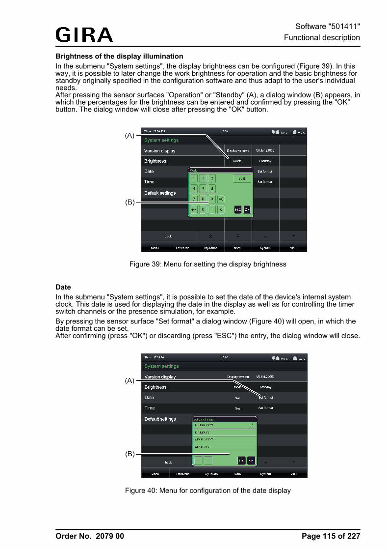
Order No. 2079 00
Brightness of the display illuminationIn the submenu "System settings", the display brightness can be configured (Figure 39). In thisway, it is possible to later change the work brightness for operation and the basic brightness forstandby originally specified in the configuration software and thus adapt to the user's individualneeds.After pressing the sensor surfaces "Operation" or "Standby" (A), a dialog window (B) appears, inwhich the percentages for the brightness can be entered and confirmed by pressing the "OK"button. The dialog window will close after pressing the "OK" button.
Figure 39: Menu for setting the display brightness
DateIn the submenu "System settings", it is possible to set the date of the device's internal systemclock. This date is used for displaying the date in the display as well as for controlling the timerswitch channels or the presence simulation, for example.By pressing the sensor surface "Set format" a dialog window (Figure 40) will open, in which thedate format can be set.After confirming (press "OK") or discarding (press "ESC") the entry, the dialog window will close.
Figure 40: Menu for configuration of the date display
Page 115 of 227
Software "501411"Functional description
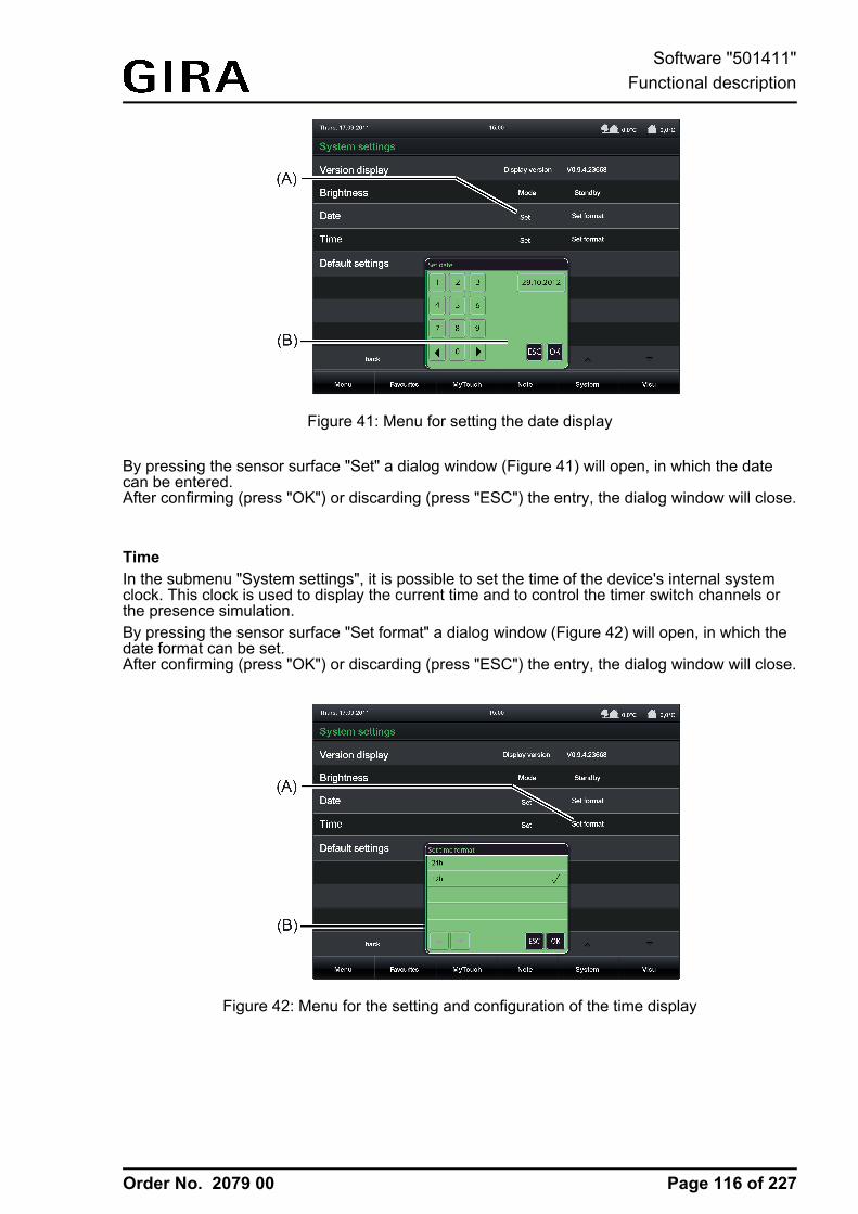
Order No. 2079 00
Figure 41: Menu for setting the date display
By pressing the sensor surface "Set" a dialog window (Figure 41) will open, in which the datecan be entered.After confirming (press "OK") or discarding (press "ESC") the entry, the dialog window will close.
TimeIn the submenu "System settings", it is possible to set the time of the device's internal systemclock. This clock is used to display the current time and to control the timer switch channels orthe presence simulation.By pressing the sensor surface "Set format" a dialog window (Figure 42) will open, in which thedate format can be set.After confirming (press "OK") or discarding (press "ESC") the entry, the dialog window will close.
Figure 42: Menu for the setting and configuration of the time display
Page 116 of 227
Software "501411"Functional description
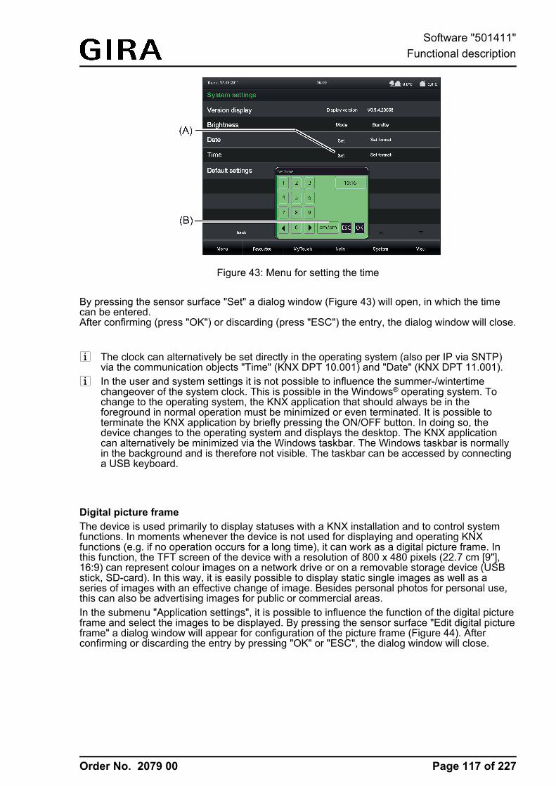
Order No. 2079 00
Figure 43: Menu for setting the time
By pressing the sensor surface "Set" a dialog window (Figure 43) will open, in which the timecan be entered.After confirming (press "OK") or discarding (press "ESC") the entry, the dialog window will close.
i The clock can alternatively be set directly in the operating system (also per IP via SNTP)via the communication objects "Time" (KNX DPT 10.001) and "Date" (KNX DPT 11.001).
i In the user and system settings it is not possible to influence the summer-/wintertimechangeover of the system clock. This is possible in the Windows® operating system. Tochange to the operating system, the KNX application that should always be in theforeground in normal operation must be minimized or even terminated. It is possible toterminate the KNX application by briefly pressing the ON/OFF button. In doing so, thedevice changes to the operating system and displays the desktop. The KNX applicationcan alternatively be minimized via the Windows taskbar. The Windows taskbar is normallyin the background and is therefore not visible. The taskbar can be accessed by connectinga USB keyboard.
Digital picture frameThe device is used primarily to display statuses with a KNX installation and to control systemfunctions. In moments whenever the device is not used for displaying and operating KNXfunctions (e.g. if no operation occurs for a long time), it can work as a digital picture frame. Inthis function, the TFT screen of the device with a resolution of 800 x 480 pixels (22.7 cm [9"],16:9) can represent colour images on a network drive or on a removable storage device (USBstick, SD-card). In this way, it is easily possible to display static single images as well as aseries of images with an effective change of image. Besides personal photos for personal use,this can also be advertising images for public or commercial areas.In the submenu "Application settings", it is possible to influence the function of the digital pictureframe and select the images to be displayed. By pressing the sensor surface "Edit digital pictureframe" a dialog window will appear for configuration of the picture frame (Figure 44). Afterconfirming or discarding the entry by pressing "OK" or "ESC", the dialog window will close.
Page 117 of 227
Software "501411"Functional description
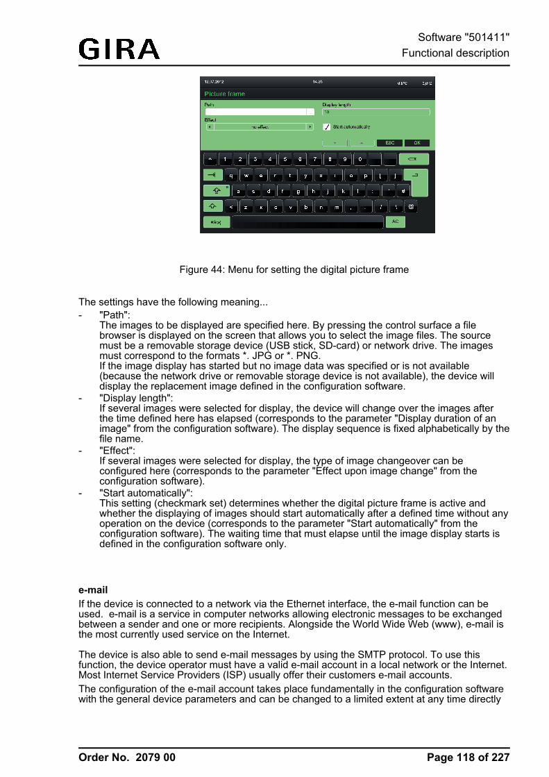
Order No. 2079 00
Figure 44: Menu for setting the digital picture frame
The settings have the following meaning...- "Path":
The images to be displayed are specified here. By pressing the control surface a filebrowser is displayed on the screen that allows you to select the image files. The sourcemust be a removable storage device (USB stick, SD-card) or network drive. The imagesmust correspond to the formats *. JPG or *. PNG.If the image display has started but no image data was specified or is not available(because the network drive or removable storage device is not available), the device willdisplay the replacement image defined in the configuration software.
- "Display length":If several images were selected for display, the device will change over the images afterthe time defined here has elapsed (corresponds to the parameter "Display duration of animage" from the configuration software). The display sequence is fixed alphabetically by thefile name.
- "Effect":If several images were selected for display, the type of image changeover can beconfigured here (corresponds to the parameter "Effect upon image change" from theconfiguration software).
- "Start automatically":This setting (checkmark set) determines whether the digital picture frame is active andwhether the displaying of images should start automatically after a defined time without anyoperation on the device (corresponds to the parameter "Start automatically" from theconfiguration software). The waiting time that must elapse until the image display starts isdefined in the configuration software only.
e-mailIf the device is connected to a network via the Ethernet interface, the e-mail function can beused. e-mail is a service in computer networks allowing electronic messages to be exchangedbetween a sender and one or more recipients. Alongside the World Wide Web (www), e-mail isthe most currently used service on the Internet.
The device is also able to send e-mail messages by using the SMTP protocol. To use thisfunction, the device operator must have a valid e-mail account in a local network or the Internet.Most Internet Service Providers (ISP) usually offer their customers e-mail accounts.The configuration of the e-mail account takes place fundamentally in the configuration softwarewith the general device parameters and can be changed to a limited extent at any time directly
Page 118 of 227
Software "501411"Functional description
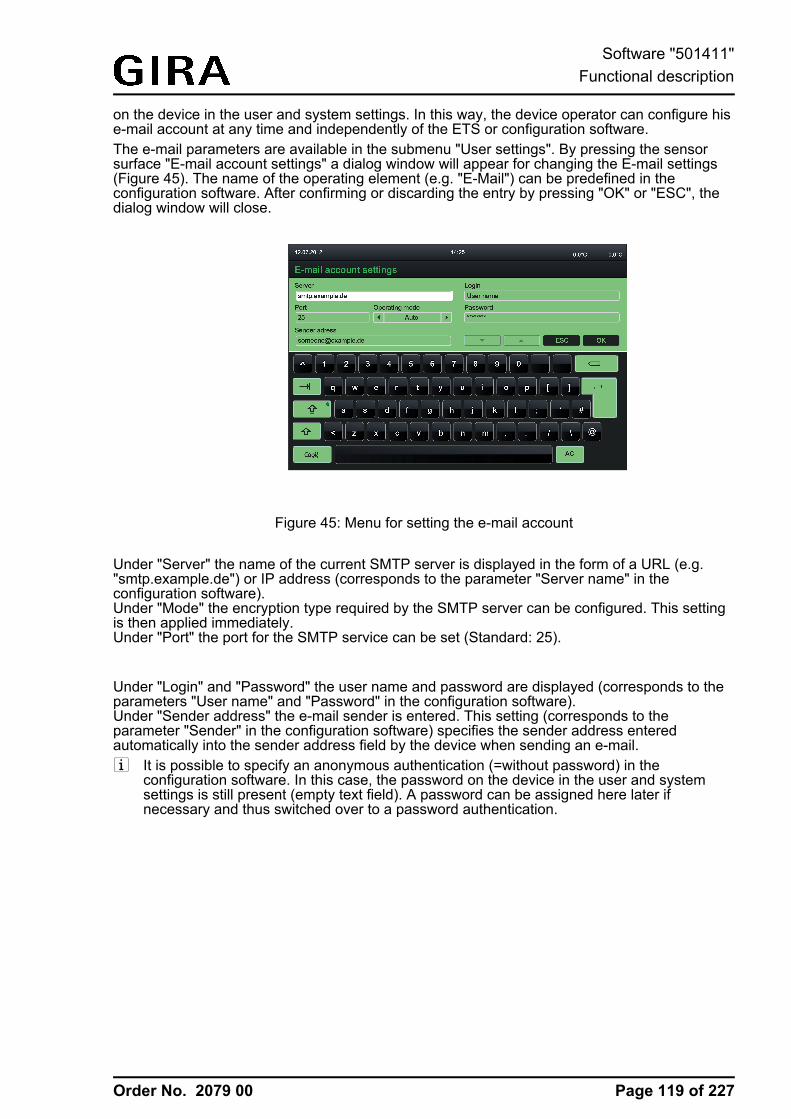
Order No. 2079 00
on the device in the user and system settings. In this way, the device operator can configure hise-mail account at any time and independently of the ETS or configuration software.The e-mail parameters are available in the submenu "User settings". By pressing the sensorsurface "E-mail account settings" a dialog window will appear for changing the E-mail settings(Figure 45). The name of the operating element (e.g. "E-Mail") can be predefined in theconfiguration software. After confirming or discarding the entry by pressing "OK" or "ESC", thedialog window will close.
Figure 45: Menu for setting the e-mail account
Under "Server" the name of the current SMTP server is displayed in the form of a URL (e.g."smtp.example.de") or IP address (corresponds to the parameter "Server name" in theconfiguration software).Under "Mode" the encryption type required by the SMTP server can be configured. This settingis then applied immediately.Under "Port" the port for the SMTP service can be set (Standard: 25).
Under "Login" and "Password" the user name and password are displayed (corresponds to theparameters "User name" and "Password" in the configuration software).Under "Sender address" the e-mail sender is entered. This setting (corresponds to theparameter "Sender" in the configuration software) specifies the sender address enteredautomatically into the sender address field by the device when sending an e-mail.i It is possible to specify an anonymous authentication (=without password) in the
configuration software. In this case, the password on the device in the user and systemsettings is still present (empty text field). A password can be assigned here later ifnecessary and thus switched over to a password authentication.
Page 119 of 227
Software "501411"Functional description
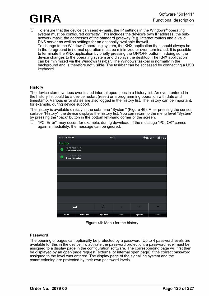
Order No. 2079 00
i To ensure that the device can send e-mails, the IP settings in the Windows® operatingsystem must be configured correctly. This includes the device's own IP address, the sub-network mask, the addresses of the standard gateway (e.g. Internet router) and a validDNS server as well as settings for an optionally available firewall.To change to the Windows® operating system, the KNX application that should always bein the foreground in normal operation must be minimized or even terminated. It is possibleto terminate the KNX application by briefly pressing the ON/OFF button. In doing so, thedevice changes to the operating system and displays the desktop. The KNX applicationcan be minimized via the Windows taskbar. The Windows taskbar is normally in thebackground and is therefore not visible. The taskbar can be accessed by connecting a USBkeyboard.
HistoryThe device stores various events and internal operations in a history list. An event entered inthe history list could be a device restart (reset) or a programming operation with date andtimestamp. Various error states are also logged in the history list. The history can be important,for example, during device support.The history is available directly in the submenu "System" (Figure 46). After pressing the sensorsurface "History", the device displays the history list. You can return to the menu level "System"by pressing the "back" button in the bottom left-hand corner of the screen.i "I2C: Error": may occur, for example, during download. If the message "I2C: OK" comes
again immediately, the message can be ignored.
Figure 46: Menu for the history
PasswordThe opening of pages can optionally be protected by a password. Up to 4 password levels areavailable for this in the device. To activate the password protection, a password level must beassigned to a display page in the configuration software. The corresponding page will first thenbe displayed by an open page request (external or internal open page) if the correct passwordassigned to the level was entered. The display page of the signalling system and thecommissioning are protected by their own password levels.
Page 120 of 227
Software "501411"Functional description
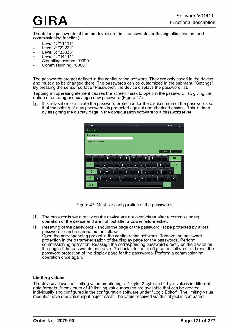
Order No. 2079 00
The default passwords of the four levels are (incl. passwords for the signalling system andcommissioning function)... - Level 1: "11111"- Level 2: "22222"- Level 3: "33333"- Level 4: "44444"- Signalling system: "9999"- Commissioning: "0000"
The passwords are not defined in the configuration software. They are only saved in the deviceand must also be changed there. The passwords can be customized in the submenu "Settings".By pressing the sensor surface "Password", the device displays the password list.Tapping an operating element causes the screen mask to open in the password list, giving theoption of entering and saving a new password (Figure 47).i It is advisable to activate the password protection for the display page of the passwords so
that the setting of new passwords is protected against unauthorised access. This is doneby assigning the display page in the configuration software to a password level.
Figure 47: Mask for configuration of the passwords
i The passwords set directly on the device are not overwritten after a commissioningoperation of the device and are not lost after a power failure either.
i Resetting of the passwords - should the page of the password list be protected by a lostpassword - can be carried out as follows:Open the corresponding project in the configuration software. Remove the passwordprotection in the parameterisation of the display page for the passwords. Performcommissioning operation. Reassign the corresponding password directly on the device onthe page of the passwords and save. Go back into the configuration software and reset thepassword protection of the display page for the passwords. Perform a commissioningoperation once again.
Limiting valuesThe device allows the limiting value monitoring of 1-byte, 2-byte and 4-byte values in differentdata formats. A maximum of 40 limiting value modules are available that can be createdindividually and configured in the configuration software under "Logic Editor". The limiting valuemodules have one value input object each. The value received via this object is compared
Page 121 of 227
Software "501411"Functional description
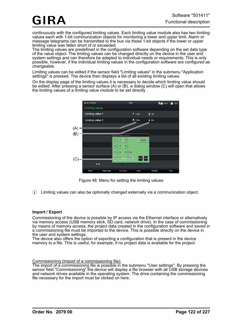
Order No. 2079 00
continuously with the configured limiting values. Each limiting value module also has two limitingvalues each with 1-bit communication objects for monitoring a lower and upper limit. Alarm ormessage telegrams can be transmitted to the bus via these 1-bit objects if the lower or upperlimiting value was fallen short of or exceeded.The limiting values are predefined in the configuration software depending on the set data typeof the value object. The limiting values can be changed directly on the device in the user andsystem settings and can therefore be adapted to individual needs or requirements. This is onlypossible, however, if the individual limiting values in the configuration software are configured aschangeable.Limiting values can be edited if the sensor field "Limiting values" in the submenu "Applicationsettings" is pressed. The device then displays a list of all existing limiting values.On the display page of the limiting values it is necessary to decide which limiting value shouldbe edited. After pressing a sensor surface (A) or (B), a dialog window (C) will open that allowsthe limiting values of a limiting value module to be set directly .
Figure 48: Menu for setting the limiting values
i Limiting values can also be optionally changed externally via a communication object.
Import / ExportCommissioning of the device is possible by IP access via the Ethernet interface or alternativelyvia memory access (USB memory stick, SD card, network drive). In the case of commissioningby means of memory access, the project data created in the configuration software and saved ina commissioning file must be imported to the device. This is possible directly on the device inthe user and system settings.The device also offers the option of exporting a configuration that is present in the devicememory to a file. This is useful, for example, if no project data is available for the project.
Commissioning (Import of a commissioning file):The import of a commissioning file is possible in the submenu "User settings". By pressing thesensor field "Commissioning" the device will display a file browser with all USB storage devicesand network drives available in the operating system. The drive containing the commissioningfile necessary for the import must be clicked on here.
Page 122 of 227
Software "501411"Functional description
Order No. 2079 00
i The number of removable storage devices or network drives displayed can be limited toensure that the device does not offer the user an unlimited number of drives on the screenin the file browser. The device does not offer more storage devices or drives on the screento choose from than defined in the parameters "Number of managed removable storagedevices" or "Number of managed network drives". These parameters are available in thegeneral device settings in the configuration software.
By pressing the sensor field "Open" you can then open the selected drive and display a list of allfolders and commissioning files (file format *.gdct9) contained therein.After selecting the desired commissioning file (only one file can be selected at a time), thesensor surface "Open" must be pressed to perform the import. The import then startsimmediately. The progress of the import is shown in the display of the device. After completingthe import, the device works immediately with the new configuration data and is ready onceagain for operation.i Before importing a new configuration file, it is advisable to make a backup of the existing
configuration by means of an export.
Commissioning Export (Export of a project file):It is possible to export an existing configuration in the device by pressing the correspondingoperating element in the submenu "Settings". The process for selecting the drive and storagelocation of the project file to be exported is essentially identical to the import process. To save aproject file, the corresponding storage location must first be selected. The sensor surface"Save" must then be pressed. Thus, a dialog window for entering the file name will open. Thesave operation is started by pressing sensor surface "OK". This might take a few seconds.i The import of the created file takes place in the configuration tool via commissioning -
reconstruction - file.
Page 123 of 227
Software "501411"Functional description
Order No. 2079 00
4.2.4.5 Fault messages
Fault messages
In contrast to the normal display and operating functions, fault messages have the followingdistinctive features...- A specific message page can be displayed irrespective of the current display page (high
display priority).- An acoustic signal can be sounded during an active message.- The user can demand an acknowledgement.- Faults can be entered in a separate message list.
4.2.4.5.1 Creating fault messages and the message window
Creating a fault messageUp to 50 different fault messages can be managed in the configuration software. Faultmessages are added to the configuration in the structure view if the entry "Fault messages" isselected in the project bar. Fault messages there can also contain a specific name.A 1-bit "Fault signal object" is created for each fault message added. The parameter "Activationby object value" defines when a message is activated via the fault signal object (e.g. activationthrough "1" telegram). The opposite value deactivates the message (e.g. deactivation through"0" telegram). In addition, a text can be specified for each fault, allowing the fault message to beidentified later.The parameter "Acoustic signal" determines whether the device plays back an audio file via theloudspeaker when there is an active fault message. It is useful to use this acoustic signallingfunction if fault messages should signal important events or states to the user of the device. Inthis case, it is advisable to use short and understandable signal tones.The device can play back media files in "*.wav" format.If individual fault messages are particularly important or fault messages can be traced back tosimilar sources (e.g. smoke detectors), other fault messages that are active at the same timecan be disabled in the device. This is done in the parameter area "Exceptions" directly in theconfiguration software for fault messages that should receive a high priority. Any one of the faultmessages configured in the device can always be selected by clicking on the button "Add faultmessage". These messages are then suppressed and thus receive a lower priority.
Message windowAs soon as a fault message is active, a warning symbol (A) appears in the header of the displayscreen (Figure 49). After pressing the symbol, a dialog window (B) will become visible. Thisdialog window contains an overview of all active fault messages in list form. Furthermore, someof the last (inactive) fault messages are also listed in the list. The fault message last activated isalways at the top of the list.The warning symbol is highlighted in red if there are fault messages that have not beenacknowledged. It turns yellow when all fault messages have been acknowledged but some ofthem are still active.
Page 124 of 227
Software "501411"Functional description
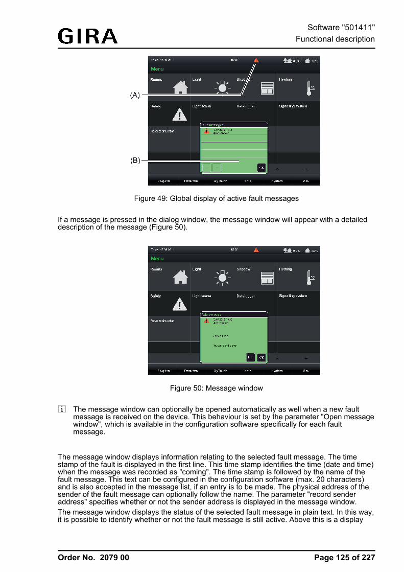
Order No. 2079 00
Figure 49: Global display of active fault messages
If a message is pressed in the dialog window, the message window will appear with a detaileddescription of the message (Figure 50).
Figure 50: Message window
i The message window can optionally be opened automatically as well when a new faultmessage is received on the device. This behaviour is set by the parameter "Open messagewindow", which is available in the configuration software specifically for each faultmessage.
The message window displays information relating to the selected fault message. The timestamp of the fault is displayed in the first line. This time stamp identifies the time (date and time)when the message was recorded as "coming". The time stamp is followed by the name of thefault message. This text can be configured in the configuration software (max. 20 characters)and is also accepted in the message list, if an entry is to be made. The physical address of thesender of the fault message can optionally follow the name. The parameter "record senderaddress" specifies whether or not the sender address is displayed in the message window.The message window displays the status of the selected fault message in plain text. In this way,it is possible to identify whether or not the fault message is still active. Above this is a display
Page 125 of 227
Software "501411"Functional description
Order No. 2079 00
text which can be configured freely in the configuration software (max. of 20 characters each).An external text received from the device via a separate 14-byte object can be displayed ifrequired. If a fault message arrives, the corresponding ASCII object is polled and the responsetelegram is displayed.The message window can be closed by pressing the "OK" button.
Page 126 of 227
Software "501411"Functional description
Order No. 2079 00
4.2.4.5.2 Acknowledgment and message list
Acknowledgement of a fault messageA fault message can either be confirmed internally by pressing the "OK" button in the messagewindow (internal acknowledgement) or via the bus by means of a separate1-bit communication object (external acknowledgement).
With internal acknowledgement, the parameter "Transmit value on acknowledgement" in theparameters of a fault enables the following acknowledgement properties of the operatingelement "Acknowledgement" to be defined in the message window...- Parameter not set: When the operating element is pressed, the acknowledgement is only
processed internally. No information is sent to other devices.- Parameter set: An additional "acknowledgement object" is made visible. When the
operating element is pressed, the acknowledgement is also sent to other devices via this1-bit object. The telegram polarity of the acknowledgement object can be configured.
i The acknowledgement is not sent in the case of external acknowledgement.An additional 1-bit communication object can be enabled for implementing externalacknowledgement. If the parameter "Allow external acknowledgement" is set, a fault messagecan also be acknowledged by other KNX devices. In this case, the "Acknowledgement receiptobject" is displayed.
i When a fault message is acknowledged, an acknowledgement event is logged in themessage list (see next section).
Message listIf necessary, it is possible to set separately in the parameters whether each fault messageshould be saved in the message list of the device. The message list is a separate display pagethat can be reached via the main menu.
The following events of a fault can be logged in the message list...- Time of the fault message, logged as "coming",- Time the fault message is retracted (fault cause eliminated), logged as "going".- Time of acknowledgement, logged as "acknowledged".
In the "Message list" parameter group of a fault message it is possible to configure which of thethree named events is logged in the message list. In addition, the "Fault text" and the timestamp are logged and displayed in the message list, thus allowing clear identification.
i The message list is deleted after a commissioning operation of the device. If the powersupply fails, the events stored in the message list are not lost.
Page 127 of 227
Software "501411"Functional description
Order No. 2079 00
4.2.4.6 Scene function
4.2.4.6.1 Definition and functionThe device can manage up to 24 internal scenes in which up to 32 different scene functions(actuator groups) can be activated that affect the KNX. The internal scenes can be controlled bythe operation functions (see page 89) as well as by a separate extension object. Control bymeans of the extension object - such as a pushbutton with a scene extension function - is onlypossible if a group address in the parameter branch of the scenes for the global scene settingsis linked with the object.The extension object according to KNX DPT 18.001 can be used both to open and save thescenes. The scene received via the object specifies which internal scene should be recalled orsaved. The configuration software automatically assigns numbers from 1 to 24 to the scenescreated. No other scene numbers are supported.The saving of scene values using the extension object is only available if the save function hasbeen enabled in the configuration software in the parameter branch of the scenes for the globalsettings.During the definition in the configuration software, scenes (1...24) are assigned to one or morescene function(s) (1...32). The scene commands are transmitted via the communication objectsof the scene functions. KNX actuators receive these commands and activate lighting andshading systems depending on the situation. When recalling a scene, the device transmits atelegram with the defined scene command via the communication objects of the assigned scenefunctions.Scene functions can be configured to the data formats "DPT 1.001 (1-bit switching)", "DPT5.001...5.004 (1-byte value)" or "DPT 9.001...9.021 (2-byte value)". The display formats forrepresenting the scene commands (switching or value) on the scene page (see page 132) canalso be configured depending on the set data type.
If scene commands are to be changed during operation of the device, the memory function ofthe device can be used. For this purpose, the actuators must first be controlled by localoperating functions or by other bus subscribers via the KNX (e. g. push-button sensors) in sucha way that the desired scene states (brightness values or blind/shutter heights) are set. Afterthat, the memory function of a scene can be executed. For this purpose, the device transmits aread request to the activated actuator communication object and awaits the responses ("Read"-flags must be set for the actuator objects!). If the activated KNX actuators return a state, thescene function saves the returned switching state or value in the non-volatile memory and thusreplaces the old scene command of the corresponding scene function. If actuators do not returnindividual states to the device, the original scene commands remain unchanged in the device.i The recalling of scenes can quickly cause a higher bus load especially if many functions
were assigned to a scene. To avoid an excessive bus load, a time delay can be configuredbetween scene telegrams (50...500 ms) in the parameter branch of the scenes for theglobal scene settings.The transmission of telegrams in the course of the storage function always takes placeimmediately.
The configuration of the scene function in the configuration software consists primarily of twosteps...- creating and defining all necessary scenes functions (1...32) incl. presetting of the scene
commands (see page 130).- creating and defining all necessary scenes (1...24) incl. assignment to the scene functions
(see page 130-131).
After commissioning the device, the preset scene names and scene commands can bechanged directly on the panel. The submenu "Edit scene" in the "System" menu is available forthis purpose.
Page 128 of 227
Software "501411"Functional description
Order No. 2079 00
i When scene names or commands are changed directly on the device by the user, thefollowing should be observed:User settings are saved in the non-volatile memory. Any changes made to scene names orscene commands by the user directly on the device are preserved after a device reset (e.g.due to mains voltage return). The user presettings are preserved even after a programmingoperation of the device if scene settings in the configuration software were not significantlychanged.If, however, elementary scene settings were changed in the configuration software, usersettings for scenes will be lost after a programming operation! User settings are thenoverwritten by the presettings of the configuration software as a result of thecommissioning operation. The following settings in the configuration software reset usersettings...- Changes to the data types of scene functions- Addition or removal of scene functions for individual scenes- Restrictions of value limits (Minimum, Maximum)
i Application example 1 (using two group addresses per scene output) of a scene recall viabrightness values (1-byte) with storage function:In this example, the 1-byte scene output object of the device is to be linked to the objects"Brightness value" and "Feedback brightness value" of a dimmer actuator via a groupaddress (here e. g. 1/1/1). It should be noted here that this group address for the actuatorobject "Feedback brightness value" is configured exclusively as a hearing address. Thetransmitting address of this object must be another group address (here e.g. 1/1/2), whichcan also be used for the feedback of the lighting brightness value to other bus devices.In this example, it is necessary to also link this second and transmitting address of thebrightness value feedback (as a hearing address) to the 1-byte scene output object of thedevice. In this way, the scene function of the device will receive the current brightnessvalue of the dimmer actuator if a value is requested and can save this with a scene savecommand.The "Read" flag must be set on the actuator object "Feedback brightness value" so that thescene storage function can be executed correctly. The actuator must always track thecurrent brightness value in the feedback object. The "Read" flag must not be set on theactuator object "Brightness value".
i Application example 2 (using only one group address per scene output) of a scene recallvia brightness values (1-byte) with storage function:This example illustrates the configuration of a scene storage function with only one groupaddress. The configuration variant described can only be used with dimmer actuatorscharacterised by special feedback behaviour or are configurable (feedback telegram only ifbrightness value changes). In case of doubt or with actuators that transmit a feedbacktelegram for every update of the input value, application example 1 (two group addressesper scene output) should be used!In this example, the 1-byte scene output object of the device is to be linked to the objects"Brightness value" and "Feedback brightness value" of a dimmer actuator via a groupaddress (here e. g. 1/1/1). The group address must be the transmitting address for theactuator object "Feedback brightness value" and scene output. In this example, it isnecessary to configure the actuator so this it only tracks the brightness value feedback ifthere is an actual change of the feedback value in the feedback object and only thentransmits a feedback telegram to the bus!In this application example, the feedback of the actuator is traced back to its input object. Ifsupplementary functions are used with the actuator, there is therefore a possibility that notall brightness states can be traced back to old presettings via the input object. Ifsupplementary functions are used, which provide for the tracking of old brightness statusesin the configuration (e.g. actuator disabling function), this application example should notbe used (Alternative: Example 1).The "Read" flag must be set on the actuator object "Feedback brightness value" so that thescene storage function can be executed correctly. The actuator must always track thecurrent brightness value in the feedback object. The "Read" flag must not be set on theactuator object "Brightness value".
Page 129 of 227
Software "501411"Functional description
Order No. 2079 00
4.2.4.6.2 Creating and defining scene functions and scenes
Creating and defining scene functionsThe scene commands are transmitted to the bus via the scene functions. KNX actuators receivethese commands and activate lighting or shading systems depending on the situation. Up to 32different scene functions can be created in the configuration software. Before the actual scenescan be defined, the required number of scene functions (equivalent to actuator group) must becreated and configured.The configuration of the scenes can be accessed via the project bar in the configurationsoftware by clicking on the entry "Scene function". Afterwards, scene functions can be added inthe structure view. After adding the scene functions, they should immediately be given clearnames for additional clarity and identification (e.g. "ceiling luminaires", "wall luminaires"). Thenames can be edited by a soft click.i Scene functions can be deleted in the structure view and thus removed from the scene
function. It should be noted here that assignments to scenes and user settings (aftercommissioning) will be lost!
One "function object" is available for each scene function in the configuration software. A groupaddress must be linked to each of these objects, which must also be linked to actuators on theKNX side. The data format of a scene function, and thus of the corresponding function object,can be configured to the data formats "DPT 1.001 (1-bit switching)", "DPT 5.001...5.004 (1-bytevalue)" or "DPT 9.001...9.021 (2-byte value)". Depending upon this, additional parameters for ascene function become visible in the configuration software, which define the display format forvalue commands (unit, offset, factor, number of digits before and after the decimal point), thesettable value range (minimum and maximum) or display formats (image texts and symbols) forswitching commands.i The transmission of scene commands via the function objects can quickly cause a higher
bus load especially if many functions were assigned to a scene. To avoid an excessive busload, a time delay can be configured between scene telegrams (50...500 ms) in theparameter branch of the light scenes for the global light scene settings.The transmission of telegrams in the course of the storage function always takes placeimmediately.
Creating and defining scenesAfter creating and defining all necessary scene functions in the configuration software, theactual scenes can be created and configured. During the course of the configuration, anynumber of the existing scene functions (1...32) are assigned to the individual scenes for whichindividual scene commands can then be configured ("ON", "OFF", brightness values etc.). Thismakes the activation of KNX actuator groups then possible.The configuration of the scenes can be accessed via the project bar in the configurationsoftware by clicking on the entry "Scenes". Afterwards, up to 24 scenes can be added in thestructure view. After adding the scenes, they should immediately be given clear names foradditional clarity and identification (e.g. "Scene TV", "Scene dining", "Scene guest"). The namescan be edited by a soft click.The user can change scene names on the device later after commissioning if this was enabled(activate parameter "Allow adaptation of the scene by the user").i On adding, the light scenes receive their light scene number automatically, with which they
can be opened later using the extension object.i Scenes can be deleted in the structure view and thus removed from the scene function. It
should be noted here that the user settings will be lost after commissioning!
It is possible to assign scene functions to a scene in the work area of the configuration software.To do this, a scene must first be selected in the structure view by mouse click. After that, allscene functions or just a individual scene functions can be selected and assigned to the scene.
Page 130 of 227
Software "501411"Functional description
Order No. 2079 00
Scene functions that have already been assigned appear in list form in the work area. Functionsassignments can subsequently be changed by clicking on the name of the scene functions.i Assignments of scene functions to scenes can be deleted in the work area. It should be
noted here that the user settings will be lost after commissioning!
The actual scene commands can be defined during the further course of the scene functionconfiguration. The commands which can be edited here align themselves to the set data anddisplay format of the individual scene functions.Lastly, you can define whether the function in a scene recall or scene storage function is activeor not for each scene function contained in a scene. Telegrams are transmitted via the functionobjects when recalling a scene or saving only for scene functions that are set to "active" in thecorresponding scene. Inactive scene functions behave passively (no telegram transmission).i The characteristics of scenes, whether the scene functions contained are active or passive,
can be changed on the device later at any time after commissioning. This means that theuser can hide individual actuator groups from scenes or add them to scenes as required.
Scenes are created and predefined as described in the configuration software. Aftercommissioning the device, the user can change the preset scene names and scene commands.The submenu "Edit scene" in the "System" menu is available for this purpose.In the configuration software you can define whether or not it should be possible to changescenes on the device. For this purpose, the parameter "Allow adaptation of the scene by theuser" is available per scene. If this parameter is not set, the scene concerned cannot be editedvia the scene page.
Page 131 of 227
Software "501411"Functional description
Order No. 2079 00
4.2.4.6.3 Configuration of scenes directly on the deviceAfter commissioning, scene commands can be edited directly on the device - by the installationengineer or by the user. In addition the light scene names can be modified. This requires thatediting and modification of the scene characteristics is permitted. A parameter is available perscene in the configuration software for this purpose (see page 130-131).Editing of scene commands and scene names - if allowed - is possible in the "System" menu,"Edit scene" submenu.As soon as the "Scene" menu is opened, a list of all scenes created in the device will bedisplayed. Up to 8 scenes are displayed simultaneously. If more than 8 scenes have beencreated, the list can be switched by the sensor surfaces ¬ / ¯.Scenes can be edited and adapted via the "Edit scenes" menu if this was enabled in theconfiguration software. If scenes are not adaptable, no submenu will open after clicking onthese scenes.i The submenu with the functions "Rename scene", "Execute scene", "Learn scene" and
"Edit scene" is recalled by touching any adaptable scene. With "Rename scene" the usercan change the predefined scene names in the configuration software at any time.In the editing mode, an on-screen keyboard is displayed. After entering the desired nameusing the keyboard, the new name is saved in the device memory by pressing the "OK"surface. By pressing the "ESC" surface the system returns to the screen page withoutsaving the name that was entered. In this case, the original scene name remainsunchanged.
Figure 51: Example of Edit scenes submenu
If you touch the sensor surface of an adaptable scene with your finger, the device branches tothe submenu of the scene submenu. There, the display will show the possible executablefunctions "Rename scene", "Execute scene", "Learn scene" and "Edit scene", which in turn canbe executed by touching them.
Page 132 of 227
Software "501411"Functional description
Order No. 2079 00
Figure 52: Example of a scene with "Scene TV" scene submenu
Scene recall or scene storage function in the scene submenuAfter pressing the control surface "Execute scene", the device immediately recalls thecorresponding scene. Such an operation is comparable with recalling an internal scene via theKNX operating function "Scene recall" (see page 89).If the "Learn scene" control surface is pressed, a dialog query appears. After confirming with"OK", the device executes the storage function of the selected scene. At the same time, allassigned scene functions poll the current switching states or values as quickly as possible viatheir function objects in the actuator groups (ValueRead). After that, the actuators have to returnthe current state or value per scene function (ValueResponse). To make this possible, the"Read" flag on one actuator each of the different actuator groups must be set to the activatedcommunication object!The light scene function waits for a feedback of the different switching states or values in adefined time window. This waiting time depends on the number of assigned scene functions(max. 7 seconds). After the waiting time has elapsed, the device saves all returned states orvalues in the non-volatile memory and thus replaces the old scene commands by the newpresettings. If actuator groups have not given any feedback to the device, the old switching orvalue commands remain unchanged for the scene functions concerned.
Adapting scenes in the scene submenuIf you touch the sensor surface "Edit scene" with your finger, a dialog window will open in whicha new scene value can be specified directly. After confirming with "OK", the new value is saved.The representation of the configuration menu depends on the set data type of the scenefunction.
Page 133 of 227
Software "501411"Functional description
Order No. 2079 00
Figure 53: Example of a scene with "Edit scene" scene submenu
i The light scene commands set on the device are saved in the non-volatile memory and arethus not lost if the power supply fails. When changing scene commands directly on thedevice, the following should be observed:Any changes made to scene names or scene commands are preserved after a device reset(e.g. due to mains voltage return). The user presettings are preserved even after aprogramming operation of the device if scene settings in the configuration software werenot significantly changed.If, however, elementary scene settings were changed in the configuration software, usersettings for scenes will be lost after a programming operation! User settings are thenoverwritten by the presettings of the configuration software as a result of thecommissioning operation. The following settings in the configuration software reset usersettings...- Changes to the data types of scene functions- Addition or removal of scene functions for individual scenes- Restrictions of value limits (Minimum, Maximum)
You can define whether the function in a scene recall or scene storage function is active or notfor each scene function contained in a scene. Telegrams are transmitted via the function objectswhen recalling a scene or saving only for scene functions that are set to "active" in thecorresponding scene. Inactive scene functions behave passively (no telegram transmission).
Page 134 of 227
Software "501411"Functional description
Order No. 2079 00
4.2.4.7 Timer switch function
4.2.4.7.1 Definition and functionThe device has an integrated multichannel weekly timer. The timer supports up to 64 switchingchannels with a total of 128 switching times that can be distributed individually to the channels.The switching times directly affect the communication objects of the individual channels, and ifnecessary, can handle the data formats "switching 1-bit" (DPT 1.xxx), "Operating modeswitchover 4 x 1-bit", "Operating mode switchover KNX", "Scene" (for recalling an internalscene), "Value 1-byte" (DPT 5.001, 5.010. 6.010), "Value 2-byte" (DPT 9.001...9.021, 8.001,7.001) and "Value 4-byte" (DPT 14,000...14,079, 13,001, 12,001).Additionally, it is possible to also activate a random function (see page 138) and an astrofunction (see page 137-138) for brightness-dependent lighting or shading control in the morningor evening twilight for each switching time.Switching times can be configured down to the minute. Weekdays can be freely specified foreach switching time. The set weekdays specify on which days of a calendar week the timercommands are to be executed. A switching time thus consists of the time of day and weekdayinformation.At each minute mark - possibly offset by a few seconds - the timer checks the set switchingtimes. If a switching time corresponds to the current time (check for hours and minutes) as wellas the current weekday, the preset switching time command is executed. Different switchingtime commands (e.g. switching a lighting system on and off) require various switching times.If several switching times with an identical configuration (the same time and weekday) areallocated to a timer switching channel, the switching time command of the last switching timewill always be executed.
The timer is controlled by the device's internal system clock (time and date of the operatingsystem). Consequently, a valid time and current date must be preset for the correct execution ofthe switching times. The system clock can be set directly in the operating system (also per IPvia SNTP) via the communication objects "Time" (KNX DPT 10.001) and "Date"(KNX DPT 11.001) or via the user and system settings directly on the device.i The real time clock has a calendar function. Depending on the date set, the day is
determined automatically by means of the internal calendar which is necessary forprocessing the timer. The day transmitted in the KNX time telegram in compliance withDPT 10.001 is irrelevant and is discarded by the device.
i The device's internal system clock is designed as a real time clock (RTC) and has anaccuracy of approx. +/- 2 seconds per day. It is advisable to set the system clocks of alldevices once a day, for example, by a shared KNX time telegram during the night hours, sothat that the timing of all devices is synchronized even over a long period of time.The system clock has its own energy storage. This will ensure that the clock keeps onrunning interruption-free for at least 24 hours if the mains power supply fails.
When the internal clock is resynchronised, a distinction is to be made between two cases...- The clock is moved back to a time before an already executed switching time. In this case,
the programmed command is not executed again when the switching time occurs. Thedevice waits for the next switching time if there are more.
- The clock is moved forward to a time after an as yet unexecuted switching time. In thiscase, the last programmed command of the channel is carried out.
Page 135 of 227
Software "501411"Functional description
Order No. 2079 00
i The timer remains active even when the device is switched off (operating system has beenshut down) or is in standby mode (see page 186). The KNX function part (BCU) isfunctional as long as mains voltage and bus voltage are switched on.In the event of a bus voltage failure, the timer cannot transmit any telegrams. After busvoltage return, the timer checks whether switching times would have had to be carried outrecently. If this is the case, the last programmed command is carried out for the affectedchannels.
The KNX function part executes the timer commands independently. To ensure that it can alsodo this, the KNX function part needs regular information regarding the switching times that werelast programmed by the installation engineer or user when the operating system and thus theKNX application are in standby mode. The KNX function part can temporarily store and executethe switching times every 24 hours. If the temporarily stored switching times have beenexecuted, the KNX function part must be resynchronised with switching times.The synchronisation takes place cyclically depending on the time of day, or when the KNXmodule has executed all switching times in one day. In the configuration software for the globaltimer parameters, you can define at what time of day the recurrent synchronisation should takeplace. The parameter "Time for synchronisation of the switching times" defines the time for thesynchronisation process regardless of whether or not the KNX module still has switching times.In addition, the KNX module requests switching times automatically if it has executed allswitching times in one day.The synchronisation process takes a short time. In addition, the device is reactivated from thestandby mode should this be necessary. To ensure that the reactivation and synchronisation ofthe device does not disturb the user, a time of day that is outside of the normal times of useshould be specified in the parameter for cyclical synchronisation.i The device cannot be reactivated automatically for the synchronisation if it was switched off
by the user (operating system shut down). In this case, the synchronisation of the KNXfunction part remains off. The KNX function part will then continue to work with the oldswitching times until a new synchronisation is carried out.
The configuration of the timer switch function in the configuration software consists primarily oftwo steps...- Creation and definition of all necessary timer switch channels (1...64) (see page 139-140).- Configuration of all necessary switching times (1...128) in the individual timer switch
channels (see page 140-141).
After commissioning the device, the preset switching times can be changed directly on thepanel. The sensor surface for operating the timer is available for this purpose. The dialogwindow will open by touching the sensor surface "Timer".
Page 136 of 227
Software "501411"Functional description
Order No. 2079 00
4.2.4.7.2 Astro and random function
Astro functionThe astro function allows the control of a lighting or shading system depending on sunrise andsunset as well as a limit time. The astro function can be activated separately for each switchingtime.The device calculates the time of the sunrise and sunset (astro time) automatically according tothe local geographic position (geographic co-ordinates). The setting of the co-ordinates is theprecondition for correct functioning and is carried out in the parameter node of the global timerparameters. This applies in the same way to all the timer switch channels.
When the astro function is activated, the time set in the configuration software or directly on thedevice is used as the limit time. Whether the limit time affects sunrise or sunset is evaluated bythe device according to the set time. Times between 00:00 and 11:59 are evaluated as sunriseand times between 12:00 and 23:59 as sunset.An astro function usually affects lighting (e.g. exterior lighting) or shading (e.g. roller shutters).The behaviour of the device when processing the astro switching times varies according tothese applications. The parameter "Astro: Channel affects" in the parameters of a timer switchchannel defines the astro behaviour - regardless of the data format of the communicationobjects of the channel - as follows...
- "Lighting" setting:Sunrise (switching times 00:00 - 11:59): if sunrise occurs before the set time (for examplein the summer months), then, at sunrise, the switching time command (e.g. external lightingOFF) is sent to the bus. If sunrise occurs later (for example during the winter months), thenthe switching time command is sent to the bus at the set time at the latest. When aswitching time is set in the configuration software, the appropriate time is indicated with "Atthe latest...".Sunset (switching times 12:00 - 23:59): if sunset occurs after the set time (for example inthe summer months), then the switching time command (e.g. external lighting ON) is sentto the bus at sunset. If sunset occurs earlier (for example during the winter months), thenthe switching time command is sent to the bus at the set time at the latest. When aswitching time is set in the configuration software, the appropriate time is indicated with "Atthe latest...".
- "Shading" setting:Sunrise (switching times 00:00 - 11:59): if sunrise occurs after the set time (for example inthe winter months), then the switching time command (e.g. roller shutters UP) is only sentto the bus at sunrise. If sunrise occurs earlier (for example during the summer months), theswitching time command is first transmitted to the bus at the set time. When a switchingtime is set in the configuration software, the appropriate time is indicated with "At thelatest...".Sunset (switching times 12:00 - 23:59): if sunset occurs before the set time (for example inthe winter months), then the switching time command (e.g. roller shutter DOWN) is sentdirectly to the bus at sunset. If sunset occurs later (for example during the summermonths), then the switching time command is sent to the bus at the set time at the latest.When a switching time is set in the configuration software, the appropriate time is indicatedwith "At the latest...".
Optionally, the astro time for the morning and evening determined by the device can bestatically shifted in the minute range (-120...0...+120). Thus, the switching times influenced byastro can be individually adapted to local conditions (e.g. influence by high mountains orforests). In the configuration software the astro shift is defined for a timer switch channel by aparameter "Astro: Offset morning " and "Astro: Offset evening".
Page 137 of 227
Software "501411"Functional description
Order No. 2079 00
i Depending on the geographic position of the location, the astro times for sunrise andsunset will vary by several hours. If a switching time with an active astro function affectsanother switching time of the timer switch channel, then the astro function is not executed.Example: a switching time is set to 17:00, astro function active (seasonal sunset between16:00 and 22:00), an additional switching time is set to 19:00 -> In this case, the secondtime (19:00) would be affected by the astro function, meaning that it would be deactivatedfor the affected switching time(s). The same would apply, if both switching times in theexample had the astro function active.
i The default coordinates are set for Kassel.
Random functionThe switching times of a channel can be triggered offset in a set random period. The randomfunction can be activated separately for each timer switch channel and affects all the switchingtimes of the appropriate channel.Each day at 00:00, the device calculates a time offset individually and randomly for eachswitching time, by which a switching time is brought forward minute-by-minute (-) or is set back(+). The maximum time offset between the set switching time and the actual time of the versioncan be configured in the configuration software for each timer switch channel using theparameter "Random: max time offset". This allows time offsets of between 1 and 30 minutes.The setting "0" for the time offset completely deactivates the random function for the timerswitch channel. The device randomly determines a time from the configured maximum timeoffset and adds this time either to the set switching time or, alternatively, subtracts it from theswitching time.
i It is not possible to transfer the switching times into the previous or next day using the timeoffset, i.e. the random function does not extended beyond the ends of days. If a randomlycalculated time offset of a switching time go beyond the end of a day, then the randomfunction for the affected switching time is not executed. The same applies when therandom time offset affects other switching times in the timer switch channel. When usingthe random function to specify the switching times of a channel, care should be taken toensure that the individual switching times are apart by at least +/- the maximum time offset,as configured in the configuration software.Example: maximum time offset = +/- 30 minutes, one switching time set to 11:00, randomfunction active -> other switching times of the channel may be between 00:00 ... 10:30 and11:30 ... 23:59. The same applies to additional switching times with a random function.
i If, in addition to the random function, an astro function is also activated, then the followingprioritisation applies to the calculation of the switching time:1. Astro time complying with "Not before..." / "At the latest..."2. The random time is added or subtracted to the time calculated under 1.
Page 138 of 227
Software "501411"Functional description
Order No. 2079 00
4.2.4.7.3 Creating and defining timer switch channels and switching times
Creating and defining timer switch channelsThe commands of the switching times are transmitted to the bus via the communication objectsof the timer switch channels. KNX actuators receive these commands and activate, for example,lighting or shading systems time-controlled. Up to 64 different timer switch channels can becreated in the configuration software. The switching times are configured during the definition ofthe individual timer switch channels.The configuration of the timer switch channels can be accessed via the project bar in theconfiguration software by clicking on the entry "Timer". Afterwards, timer switch channels can beadded in the structure view. After adding the timer switch channels, they should immediately begiven clear names for additional clarity and identification (e.g. "external lighting", "move venetianblinds"). The names can be edited by a soft click.i Timer switch channels can be deleted in the structure view and thus removed from the
timer. It should be noted here that the user settings on switching times (aftercommissioning) will be lost!
One communication object is available for each timer switch channel in the configurationsoftware. A group address must be linked to each of these objects, which must also be linked toactuators on the KNX side. The data format of a timer switch channel and thus thecorresponding object can be configured alternatively to "Switching", "Operating modeswitchover" (4 x 1-bit or KNX)", "Scene" or to value formats (1-byte, 2-byte, 4-byte with differentformats and value ranges). Depending upon this, additional parameters for a timer switchchannel become visible in the configuration software, which define the display format for valuecommands (unit, offset, factor, number of digits before and after the decimal point), theadjustable value range (minimum and maximum) or display formats (image texts and symbols).
Data type Statuselements
Value range
Switching Image text "0" (OFF) / "1" (ON)
Operating modeswitchover 4 x 1 bit
Image texts Comfort, Standby, Night operation, Night reduction,Frost/heat protection
Operating modeswitchover KNX
Image texts Automatic, Comfort, Standby, Night operation, Nightreduction, Frost/heat protection
Scene Scene name internal scenes
1-byte value (5.00x) Status value(formatted)
%: 0...100°: 0...360user-defined: 0...255
1-byte value (5.010) Status value(formatted)
0...255
1-byte value (6.010) Status value(formatted)
-128...127
2-byte value (7.001) Status value(formatted)
0...65535
2-byte value (8.001) Status value(formatted)
-32768...32767
2-byte value (9.0xx) Status value(formatted)
-671089...670761
4-byte value (12.001) Status value(formatted)
0...4294967295
Page 139 of 227
Software "501411"Functional description
Order No. 2079 00
4-byte value (13.001) Status value(formatted)
-2147483648...2147483647
4-byte value (14.0xx) Status value(formatted)
-214748365...214748365
Configurable data types and status elements for timer switch channelsi The value ranges of the value data types can be limited by parameters in the configuration
software.i With the data type "Scene", internal scenes are recalled via the switching times. For this
purpose, at least one internal scene must have been created in the device!
A disabling object is optionally available for every timer switch channel. Timer switch channelscan be locked via the disabling objects during the running time of the device. In these cases, theobjects of the timer switch channels do not transmit when a switching time occurs. The telegrampolarity of the individual disabling objects (which telegram is disabled or enabled) can beconfigured on the parameter page of a timer switch channel.If the parameter "Transmit after disabling is enabled" is set, the device evaluates the configuredswitching times upon re-enabling. If one or more switching times were not executed during thepreviously active disable phase, the device carries out the execution of the last switching timeand transmits a corresponding telegram to the bus via the communication object of the timerswitch channel. If the parameter "Transmit after disabling is enabled" is not set, the switchingtimes will be ignored upon re-enabling. In this case, switching times skipped by the disablingfunction are not carried out.
Defining switching timesAfter creating and defining all necessary timer switch channels in the configuration software, theactual switching times can be created and defined. Switching times are created and defined fora timer switch channel in its parameter structure in the work area of the configuration software.It is possible to add switching times - if a timer switch channel was selected - in the work area ofthe configuration software. Up to 128 switching times can be created in the entire device, whichare distributed to the individual timer switch channels. At least one switching time should becreated for each timer switch channel.
A switching time has the following parameters...- Parameter field "Value": This parameter defines the value of the switching time. The
adjustable value depends on the configured data format of the corresponding timer switchchannel.
- Parameter fields of the weekdays: The weekdays on which the switching time event is totake place are defined here.
- Parameter field "Switching time": The actual switching time is defined here. The setting ismade in the 24-hour format.
- Parameter field "Astro": The presetting whether the astro function is activated for theswitching time is made here. The astro function can be activated individually for eachswitching time. The function of the astro function and its optional time offset are defined inthe parameters of the corresponding timer switch channel.
- Parameter field "Random": This parameter is used to preset whether the random function isactivated for the switching time. The random function can be activated individually for eachswitching time. The maximum time offset for the random function is defined in theparameters of the corresponding timer switch channel.
Page 140 of 227
Software "501411"Functional description
Order No. 2079 00
i When switching times are changed directly on the device by the user, the following shouldbe observed:User settings are saved in the non-volatile memory. Any changes made by the user directlyon the device are preserved after a device reset (e.g. due to mains voltage return). Theuser presettings are preserved even after a programming operation of the device if settingsfor timer switch channels or switching times in the configuration software were notsignificantly changed.If, however, elementary settings were changed in the configuration software, user settingsfor timer switch channels will be lost after a programming operation! User settings are thenoverwritten by the presettings of the configuration software as a result of thecommissioning operation. The following settings in the configuration software reset usersettings...- Changes to the data types of timer switch channels- Addition or removal of switching times for timer switch channels- Restrictions of value limits (Minimum, Maximum)
Assigning timer switching channel to a functionTimer switching channels created in the configuration software must be assigned to any functionduring commissioning on the device. Only then will these functions be executed at theconfigured switching times.For this purpose, the timer switching channel desired must be selected in the chosen functionunder "Display - timer switching channel".If no switching times have been programmed yet in the configuration software, a white clocksymbol will appear in the display to indicate an incomplete setup. If switching times have beenprogrammed, the clock symbol will be green.
Page 141 of 227
Software "501411"Functional description
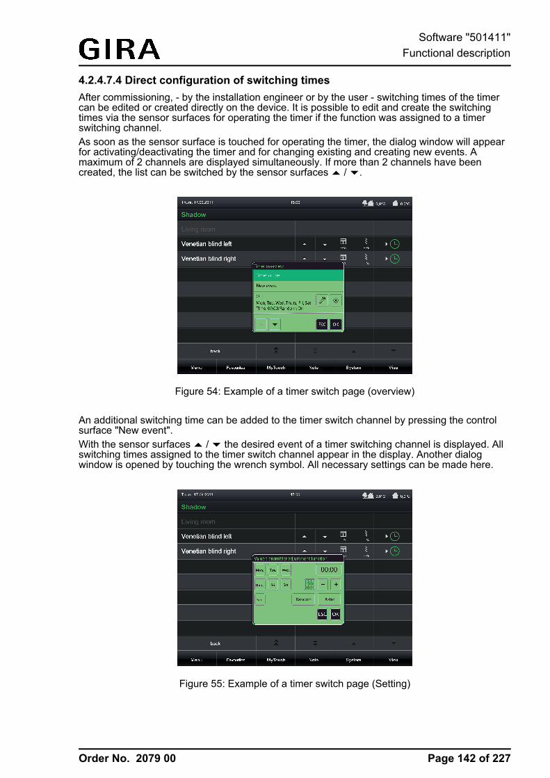
Order No. 2079 00
4.2.4.7.4 Direct configuration of switching timesAfter commissioning, - by the installation engineer or by the user - switching times of the timercan be edited or created directly on the device. It is possible to edit and create the switchingtimes via the sensor surfaces for operating the timer if the function was assigned to a timerswitching channel.As soon as the sensor surface is touched for operating the timer, the dialog window will appearfor activating/deactivating the timer and for changing existing and creating new events. Amaximum of 2 channels are displayed simultaneously. If more than 2 channels have beencreated, the list can be switched by the sensor surfaces ¬ / ¯.
Figure 54: Example of a timer switch page (overview)
An additional switching time can be added to the timer switch channel by pressing the controlsurface "New event".With the sensor surfaces ¬ / ¯ the desired event of a timer switching channel is displayed. Allswitching times assigned to the timer switch channel appear in the display. Another dialogwindow is opened by touching the wrench symbol. All necessary settings can be made here.
Figure 55: Example of a timer switch page (Setting)
Page 142 of 227
Software "501411"Functional description
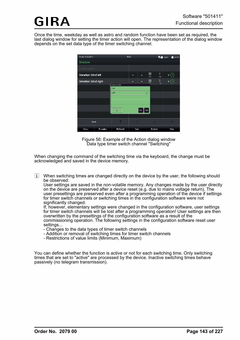
Order No. 2079 00
Once the time, weekday as well as astro and random function have been set as required, thelast dialog window for setting the timer action will open. The representation of the dialog windowdepends on the set data type of the timer switching channel.
Figure 56: Example of the Action dialog windowData type timer switch channel "Switching"
When changing the command of the switching time via the keyboard, the change must beacknowledged and saved in the device memory.
i When switching times are changed directly on the device by the user, the following shouldbe observed:User settings are saved in the non-volatile memory. Any changes made by the user directlyon the device are preserved after a device reset (e.g. due to mains voltage return). Theuser presettings are preserved even after a programming operation of the device if settingsfor timer switch channels or switching times in the configuration software were notsignificantly changed.If, however, elementary settings were changed in the configuration software, user settingsfor timer switch channels will be lost after a programming operation! User settings are thenoverwritten by the presettings of the configuration software as a result of thecommissioning operation. The following settings in the configuration software reset usersettings...- Changes to the data types of timer switch channels- Addition or removal of switching times for timer switch channels- Restrictions of value limits (Minimum, Maximum)
You can define whether the function is active or not for each switching time. Only switchingtimes that are set to "active" are processed by the device. Inactive switching times behavepassively (no telegram transmission).
Page 143 of 227
Software "501411"Functional description
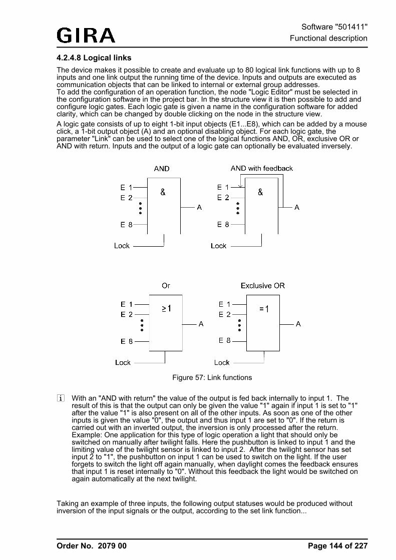
Order No. 2079 00
4.2.4.8 Logical linksThe device makes it possible to create and evaluate up to 80 logical link functions with up to 8inputs and one link output the running time of the device. Inputs and outputs are executed ascommunication objects that can be linked to internal or external group addresses.To add the configuration of an operation function, the node "Logic Editor" must be selected inthe configuration software in the project bar. In the structure view it is then possible to add andconfigure logic gates. Each logic gate is given a name in the configuration software for addedclarity, which can be changed by double clicking on the node in the structure view.A logic gate consists of up to eight 1-bit input objects (E1...E8), which can be added by a mouseclick, a 1-bit output object (A) and an optional disabling object. For each logic gate, theparameter "Link" can be used to select one of the logical functions AND, OR, exclusive OR orAND with return. Inputs and the output of a logic gate can optionally be evaluated inversely.
Figure 57: Link functions
i With an "AND with return" the value of the output is fed back internally to input 1. Theresult of this is that the output can only be given the value "1" again if input 1 is set to "1"after the value "1" is also present on all of the other inputs. As soon as one of the otherinputs is given the value "0", the output and thus input 1 are set to "0". If the return iscarried out with an inverted output, the inversion is only processed after the return.Example: One application for this type of logic operation a light that should only beswitched on manually after twilight falls. Here the pushbutton is linked to input 1 and thelimiting value of the twilight sensor is linked to input 2. After the twilight sensor has setinput 2 to "1", the pushbutton on input 1 can be used to switch on the light. If the userforgets to switch the light off again manually, when daylight comes the feedback ensuresthat input 1 is reset internally to "0". Without this feedback the light would be switched onagain automatically at the next twilight.
Taking an example of three inputs, the following output statuses would be produced withoutinversion of the input signals or the output, according to the set link function...
Page 144 of 227
Software "501411"Functional description
Order No. 2079 00
E 1 E 2 E 3 OutputAND
OutputOR
OutputEX OR
OutputAND withfeedback
0 0 0 0 0 0 0
0 0 1 0 1 1 0
0 1 0 0 1 1 0
0 1 1 0 1 0 0
1 0 0 0 1 1 0 *)
1 0 1 0 1 0 0 *)
1 1 0 0 1 0 0 *)
1 1 1 1 1 1 1
Output statuses of the logical link functions*): Input 1 is automatically reset to "0" here.
The transmission behaviours of the output of a gate can be influenced in different ways...- The parameter "Transmit on" of a gate together with the "Change the output" setting can
reduce the bus load. In this case, telegrams are only transmitted when the logical status ofthe output changes. If, for example, the result of the link in time-monitored in a rollervenetian blind actuator, it may be advisable to have the output transmit a telegram on eachinput event ("Each input event" setting).
- The gate can be disabled or enabled using the optional 1 bit disabling object. It is possibleto set for which object value the disabling is active. The transmission behaviour of the logicgate can be defined after the block has been enabled. If, during a block, the input value ischanged, then the output can automatically send a telegram, as soon as the block is lifted,or the gate waits until the next input telegram.
- The output also possesses a filter function. This sets whether it transmits each output valueor whether it can only send "1" telegrams or only "0" telegrams.
- A switch-on delay and switch-off delay can be configured if required. Depending on the settime, telegrams of the output are transmitted to the bus after a delay depending on theresult of the logical link ("1"-telegram or "0"-telegram). This function is used for suppressingbrief changes in the status. A change in the status is not transmitted to the bus if the statusshould change once again within a time delay.
- Optionally, the output of a logic gate can transmit the status cyclically to the bus (e.g. fortelegram monitoring in actuators). An output only transmits cyclically if the filter criterion ismet (see above) In the case of configured switch on / or switch off delays, the status of thecyclical telegram first changes after a logical change in status after the delay time haselapsed.
Page 145 of 227
Software "501411"Functional description
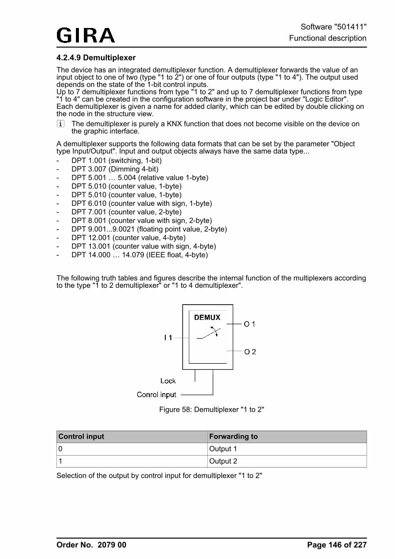
Order No. 2079 00
4.2.4.9 DemultiplexerThe device has an integrated demultiplexer function. A demultiplexer forwards the value of aninput object to one of two (type "1 to 2") or one of four outputs (type "1 to 4"). The output useddepends on the state of the 1-bit control inputs.Up to 7 demultiplexer functions from type "1 to 2" and up to 7 demultiplexer functions from type"1 to 4" can be created in the configuration software in the project bar under "Logic Editor".Each demultiplexer is given a name for added clarity, which can be edited by double clicking onthe node in the structure view.i The demultiplexer is purely a KNX function that does not become visible on the device on
the graphic interface.
A demultiplexer supports the following data formats that can be set by the parameter "Objecttype Input/Output". Input and output objects always have the same data type... - DPT 1.001 (switching, 1-bit)- DPT 3.007 (Dimming 4-bit)- DPT 5.001 … 5.004 (relative value 1-byte)- DPT 5.010 (counter value, 1-byte)- DPT 5.010 (counter value, 1-byte)- DPT 6.010 (counter value with sign, 1-byte)- DPT 7.001 (counter value, 2-byte)- DPT 8.001 (counter value with sign, 2-byte)- DPT 9.001...9.0021 (floating point value, 2-byte)- DPT 12.001 (counter value, 4-byte)- DPT 13.001 (counter value with sign, 4-byte)- DPT 14.000 … 14.079 (IEEE float, 4-byte)
The following truth tables and figures describe the internal function of the multiplexers accordingto the type "1 to 2 demultiplexer" or "1 to 4 demultiplexer".
Figure 58: Demultiplexer "1 to 2"
Control input Forwarding to0 Output 1
1 Output 2
Selection of the output by control input for demultiplexer "1 to 2"
Page 146 of 227
Software "501411"Functional description
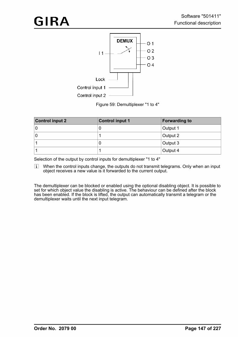
Order No. 2079 00
Figure 59: Demultiplexer "1 to 4"
Control input 2 Control input 1 Forwarding to0 0 Output 1
0 1 Output 2
1 0 Output 3
1 1 Output 4
Selection of the output by control inputs for demultiplexer "1 to 4"i When the control inputs change, the outputs do not transmit telegrams. Only when an input
object receives a new value is it forwarded to the current output.
The demultiplexer can be blocked or enabled using the optional disabling object. It is possible toset for which object value the disabling is active. The behaviour can be defined after the blockhas been enabled. If the block is lifted, the output can automatically transmit a telegram or thedemultiplexer waits until the next input telegram.
Page 147 of 227
Software "501411"Functional description
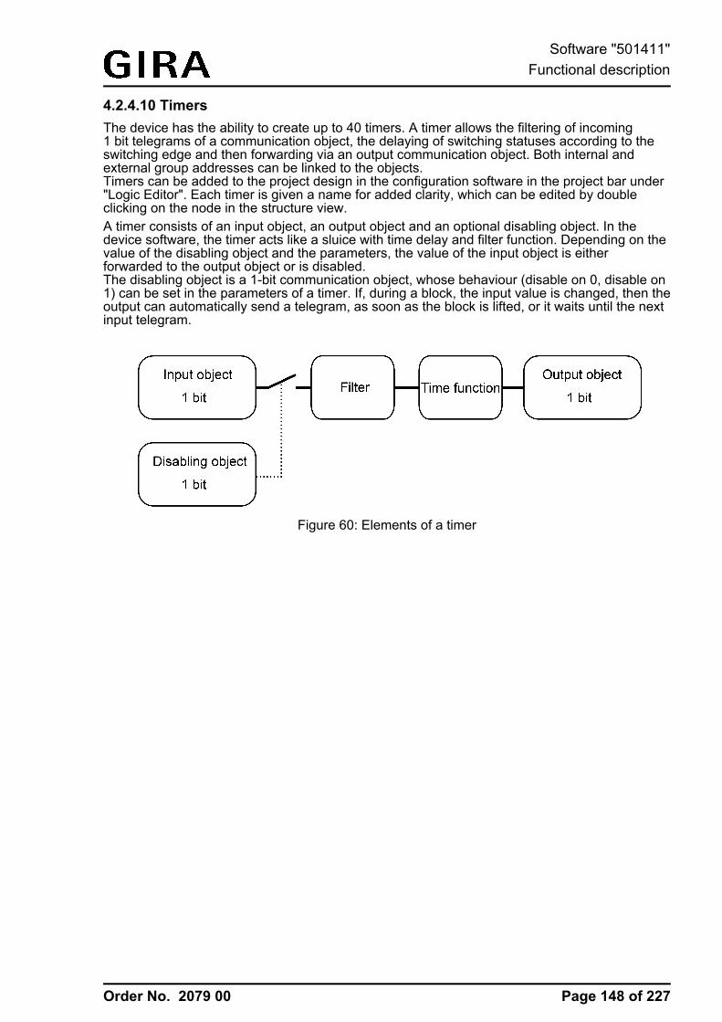
Order No. 2079 00
4.2.4.10 TimersThe device has the ability to create up to 40 timers. A timer allows the filtering of incoming1 bit telegrams of a communication object, the delaying of switching statuses according to theswitching edge and then forwarding via an output communication object. Both internal andexternal group addresses can be linked to the objects.Timers can be added to the project design in the configuration software in the project bar under"Logic Editor". Each timer is given a name for added clarity, which can be edited by doubleclicking on the node in the structure view.A timer consists of an input object, an output object and an optional disabling object. In thedevice software, the timer acts like a sluice with time delay and filter function. Depending on thevalue of the disabling object and the parameters, the value of the input object is eitherforwarded to the output object or is disabled.The disabling object is a 1-bit communication object, whose behaviour (disable on 0, disable on1) can be set in the parameters of a timer. If, during a block, the input value is changed, then theoutput can automatically send a telegram, as soon as the block is lifted, or it waits until the nextinput telegram.
Figure 60: Elements of a timer
Page 148 of 227
Software "501411"Functional description
Order No. 2079 00
4.2.4.11 Limiting valuesThe device allows the limiting value monitoring of 1-byte, 2-byte and 4-byte values in differentdata formats. A maximum of 40 limiting value modules are available that can be createdindividually and configured in the configuration software under "Logic Editor" in the project bar.The limiting value modules have one value input object each. The value received via this objectis compared continuously with the configured limiting values. Each limiting value module alsohas two limiting values each with 1-bit communication objects for monitoring a lower and upperlimit. Alarm or message telegrams can be transmitted to the bus via these 1-bit objects if thelower or upper limiting value was fallen short of or was exceeded in each case.
A limiting value module has the following characteristics and parameters...- "Datapoint type":
This parameter defines the data format of the input communication object. Depending onthis setting, other parameters are visible which define the display format and unit of thevalue for displaying the user settings directly on the device ("Settings -> Limiting values")and which also define the format of the input field of the limiting values in the configurationsoftware.
- "Transmit limiting value on initialisation":If this parameter is set, the device evaluates the input value immediately after a devicereset (commissioning operation or bus voltage return) and initialises the 1-bit limiting valueobjects. Consequently, the 1-bit limiting value objects also send the current state to thebus.
- "Upper limiting value active" and "Lower limiting value active":This parameter can define whether the input value is monitored at a lower and upper limit.
- "Upper limiting value" and "Lower limiting value":These parameters define the limiting value to be monitored if these are activated. Thelimiting values predefined here can be changed on the device at any time directly in theuser and system settings and can therefore be adapted to individual needs orrequirements. The formatting of the values in the input field of the configuration softwareand in the presetting during the course of the user settings directly on the device is definedby the lower level parameters of the data point type (offset, factor, format).
- "Hysteresis upper limiting value" and "Hysteresis lower limiting value":A hysteresis is assigned to each limiting value. The hysteresis serves to prevent frequentswitching backwards and forwards when there is a measured value in the approximatearea of the limiting value (Figure 62). The setting "0" deactivates the hysteresis (Figure 61).In the case of the upper limiting value, the hysteresis is deducted from the limiting value. Inthe case of the lower limiting value, the hysteresis is added to the limiting value. Thehysteresis - like the limiting value itself - is an absolute value and is only defined in theconfiguration software.
Page 149 of 227
Software "501411"Functional description
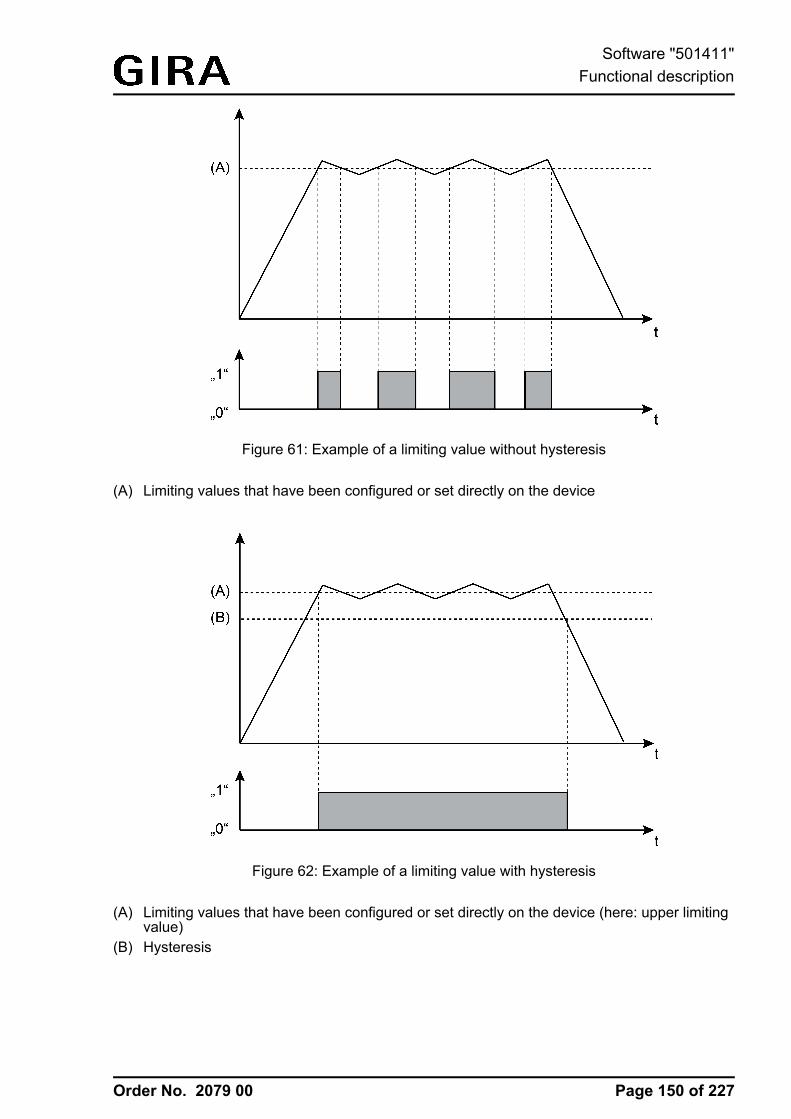
Order No. 2079 00
Figure 61: Example of a limiting value without hysteresis
(A) Limiting values that have been configured or set directly on the device
Figure 62: Example of a limiting value with hysteresis
(A) Limiting values that have been configured or set directly on the device (here: upper limitingvalue)
(B) Hysteresis
Page 150 of 227
Software "501411"Functional description
Order No. 2079 00
- "Behaviour on exceeding the upper limiting value", "Behaviour on not reaching upperlimiting value – hysteresis", "Behaviour on not reaching lower limiting value", "Behaviour onexceeding upper limiting value + hysteresis":These parameters define the switching commands transmitted to the bus via the 1-bitlimiting value object. The device compares the current input value continuously with the setlimiting values and hystereses and decides on this basis which switching command shouldbe transmitted.
- "Transmission delay upper limiting value" and "Transmission delay lower limiting value":The switching telegrams of the limiting value object can be transmitted to the bus after adelay if required. This function is used for suppressing brief changes in the status. Achange in the status is not transmitted to the bus if the status should change once againwithin a time delay.
- "Upper limiting value changeable" and "Lower limiting value changeable":The limiting values can be changed directly on the device in the user and system settingsand can therefore be adapted to individual needs or requirements. This is only possible,however, if the individual limiting values in the configuration software are configured aschangeable here.
- "Upper limiting value changeable externally" and "Lower limiting value changeableexternally":Limiting values can also be optionally changed externally via a communication object. Ifthese parameters are set, communication objects are also available that can change thelimiting values during the running time of the device. The data format of these objectscorresponds to the datapoint type of the limiting value set in the configuration software.
Page 151 of 227
Software "501411"Functional description
Order No. 2079 00
4.2.4.12 e-mailIf the device is connected to a network via the Ethernet interface and the IP communicationparameters are set correctly in the Windows® operating system, the E-Mail function can beused. e-mail is a service in computer networks allowing electronic messages to be exchangedbetween a sender and one or more recipients. Alongside the World Wide Web (www), e-mail isthe most currently used service on the Internet.The device is also able to send e-mail messages. To use this function, the device operator musthave a valid e-mail account in a local network or the Internet. Most Internet Service Providers(ISP) usually offer their customers e-mail accounts.The configuration of the e-mail accounts takes place directly on the device in the user andsystem settings (see page 110). In this way, the device operator can configure his e-mailaccount at any time and independently of the ETS or configuration software.i The receipt of e-mails is triggered via a plug-in.
Sending e-mail messagesThe device is able to send predefined texts as "event e-mail". The text contents of the event e-mail as well as the recipient address are specified in the configuration software by the projectplanner before the device is commissioned. Sending of texts is triggered by switchingtelegrams, which receive either KNX group addresses or internal group addresses.The event mails are configured in the configuration software when the entry "E-Mail" is selectedin the project bar. Up to 50 event e-mails can then be created in the structure view. A 1-bitcommunication object is shown for each event e-mail.
Within the parameters of an event e-mail, the project planner specifies the following properties...- "Send e-mail on":
Definition of the telegram polarity for the object of the corresponding event e-mail. The e-mail is sent when a telegram is received with the polarity defined at this point. Telegramswith another polarity are rejected.
- "Recipient":Specification of the e-mail address of a recipient of the event e-mail. The standard inputformat of the address is specified as "local@domain" (example: "[email protected]").
- "Subject":Specification of the subject text of the event e-mail (e.g. "Signalling system fault","Heater frost protection", ...). The text may be a maximum of 20 characters in length.
- "Message":Specification of the text contents of the event e-mail. The specified contents text is latertransmitted to the mail server as "simple text" (plain text) in the event e-mail, and isdisplayed in the same manner, without special formatting, when the message is opened.
To enable the device to send e-mails, a valid SMTP mail server (Simple Mail Transfer Protocol)must be entered in the device configuration. The SMTP configuration is possible with thegeneral device parameters in the configuration software as well as later directly on the device inthe user and system settings.i After a device reset (return of mains power supply, commissioning operation), the device
first initialises the Ethernet interface. e-mails can only be sent when this initialisationoperation has been completed (if necessary using DHCP). After a device reset, this isusually possible after approx. 1 minute.
i The device encodes the text characters of an email message in Unicode (UTF-8).
Sending the data values of the datalogger by e-mail messageIf a datalogger channel is configured in the configuration software, the recorded data values canbe sent cyclically by e-mail. In this case, the device prepares the recorded data in CSV format
Page 152 of 227
Software "501411"Functional description
Order No. 2079 00
(values are separated by semicolons) and sends them to a specified recipient in a standard e-mail. Both the e-mail function and the recipient address can be configured in the configurationsoftware with the parameters of a datalogger channel. The e-mail is sent automatically eachtime the number of data records stored in the file system reaches 10,000. A data recordconsists of the minimum value, maximum value, average value and the last value (forcalculating a difference) of a time interval.
Page 153 of 227
Software "501411"Functional description
Order No. 2079 00
4.2.4.13 Datalogger
IntroductionThe datalogger offers the option of recording KNX data - for example temperature values,command values, lighting status, etc. - in various formats in the device memory and of showingthem in a value-time diagram on the display. In so doing, the data telegrams received from theKNX are "compressed" at set intervals and saved in a datalogger channel of the device asminimum and maximum average values and can be displayed as required. It is optionallypossible to also represent average values of the recorded data values.The datalogger is primarily subdivided into the function modules "Datalogger recording" and"Datalogger display".
4.2.4.13.1 Datalogger recordingThe KNX data are saved in a datalogger channel. A maximum of 20 datalogger channels canbe inserted in the device configuration by selecting the entry "Datalogger" in the configurationsoftware in the project bar. Afterwards, new channels can be added in the structure view. Eachdatalogger is given a name for added clarity, which can be edited by a soft click on the node inthe structure view.
Communication object and data format:Each datalogger channel possesses a communication object. The data format of this object canbe specified using the parameter "Data point type". The following data formats are available...- DPT 5.001 … 5.004 (relative value 1-byte)- DPT 5.010 (counter value, 1-byte)- DPT 6.010 (counter value with sign, 1-byte)- DPT 7.001 (counter value, 2-byte)- DPT 8.001 (counter value with sign, 2-byte)- DPT 9.001...9.0021 (floating point value, 2-byte)- DPT 12.001 (counter value, 4-byte)- DPT 13.001 (counter value with sign, 4-byte)- DPT 14.000 … 14.079 (IEEE float, 4-byte)
Interval time:Telegrams reaching the communication object are divided into various time intervals andassigned to them. At the end of each time period, the telegrams received are evaluated and aminimum and maximum interval value determined. In addition, an average value is calculatedand saved. To evaluate a differential calculation, the last respective data value of an interval isalso saved.The smallest and largest values are evaluated as the minimum and maximum values. Tocalculate the average, the recorded values are totalled and divided by the number of recordedvalues. If, within a time period, only one telegram data value was received, then the minimumvalue = maximum value = average value.
The time interval for the detection of data telegrams can be configured separately by theparameter "Interval time" for each datalogger channel. The following interval times areconfigurable...- "Minute"- "Hour"- "Day"- "Week"- "Month"
Page 154 of 227
Software "501411"Functional description
Order No. 2079 00
i The user defines the scaling of the time axis (X axis) in the value-time diagram whenreading the diagram. For this purpose, a selection of the following settings is provided inthe diagram display directly on the device: "Hour", "Day", "Week", "Month", "Year".The time axis in the diagram is shrunk or stretched depending on this setting. The settingthus defines the number of time intervals taken into account in the diagram and thereforethe number of visible data values.Example: The time axis is set to one hour. The time intervals of the previous hour aredisplayed in the diagram. The diagram then displays, for example, 60 data values of adatalogger channel with a time interval of one minute if at least one data value could alsoactually be recorded in each time interval.
i If, within a period of time, no telegram could be received and evaluated, then thecorresponding interval is considered "invalid". The characteristic curve is thus interrupted inthe value-time diagram of the on-screen display. To prevent such behaviour, the data valuesources - such as the room temperature controller, weather stations, etc. - should transmitthe telegram data value cyclically to the bus with a cycle time that is considerably shorterthan the set time period. At least two telegram data values should be received in a timeinterval. The evaluation of the minimum, maximum and average values becomes moreaccurate, the more telegrams are received in the time period.
Poll cyclically:During data recording, regular incoming telegrams (ValueWrite) or value responses or a cyclicpoll (ValueResponse) can be evaluated. Cyclical polling of the object value can be activatedseparately for each datalogger channel. With activated cyclic polling, the device transmits avalue read telegram (ValueRead) to the bus regularly, after a period of time has elapsed. Thedata source must then return a value response telegram (ValueResponse). The "Read" flagmust be set on the transmitting object of the data source for this to function correctly.The time interval of a cyclic poll can be defined in the configuration software. The setting optionsautomatically align themselves to the configured interval time. This ensures that at least onedata value is requested within a time period.i The device makes a distinction between normal telegrams (ValueWrite) and value
response telegrams. With activated cyclic polling, the minimum, maximum and averagevalues are added to the value responses. In this case, additional spontaneous telegramsare only given the maximum and minimum values.
i Cyclic polling is preferable for even average formation.
Specify start value for difference formation:If the data source is a counter (e.g. electricity meter, people counter, etc.), the data display inthe value-time diagram can be configured to differential calculation. A difference between thelast value to arrive of the current interval and the last valued of the previous interval - dependingon minimum, maximum or average value - is calculated here and displayed as a differentialvalue, provided that the diagram is configured to differential display. The calculated data valuedifferentials then, in the case of an electricity meter, directly represent the consumed units ofpower within a recording period (e.g. month or year).To ensure that the differential calculation produces useful display values, only those countervalues should be used as data which are counted in one direction (either increasing ordecreasing). In addition, differential calculation with data values not from counters is usuallymeaningless and thus impracticable. Therefore, differential calculation should only be displayedfor data channels that have "Counter" configured as the object data type.After a device reset (power failure, commissioning operation), the differential calculation shouldstart at a specified starting value. This is required in order to initialise the differential calculationso that a differential value can be calculated when starting the data recording after a reset. Thismeans that, in addition, there can be an adjustment to defined basic counter levels - forexample after the installation of a new electricity meter.The system project planner must enter the starting value in the configuration software for theparameters of a datalogger channel. This means that it is stored statically in the device projectplanning. The following points should be observed:If a value is entered in the parameter box, the device then evaluates the last data value of thefirst time period after the reset directly and then shows the difference to the starting value in thedisplay diagram. Alternatively, no start value can be defined. In this case, the device
Page 155 of 227
Software "501411"Functional description
Order No. 2079 00
automatically evaluates the first data value received as the start value. This value does notappear in the data display. Only the differential values calculated after this(last value of 1st period <-> last value of 2nd period, etc.) are transferred to the display asdisplay values.i With a set cyclic poll of the channel object, only the response telegrams (ValueResponse)
of the data source are used to record the differential data. Additional spontaneoustelegrams (ValueWrite) are not taken into account in a differential evaluation.
Send e-mail on memory overflow:If the device is connected to a network via an Ethernet connection and an e-mail account isconfigured to send e-mail messages, the data values recorded by a datalogger channel can besent by e-mail on memory overflow (>11,000 data records). In this case, the device preparesthe oldest 1,000 data records in CSV format (values are separated by semicolons) and sendsthem to a specified receiver in a standard e-mail. Afterwards, the sent data is deleted from thememory. Both the e-mail function and the recipient address can be configured in theconfiguration software with the parameters of a datalogger channel. If no recipient address isconfigured, only the oldest 1,000 data records will be deleted.A data record consists of the minimum value, maximum value, average value and the last value(for calculating a difference) of a time interval.
Page 156 of 227
Software "501411"Functional description
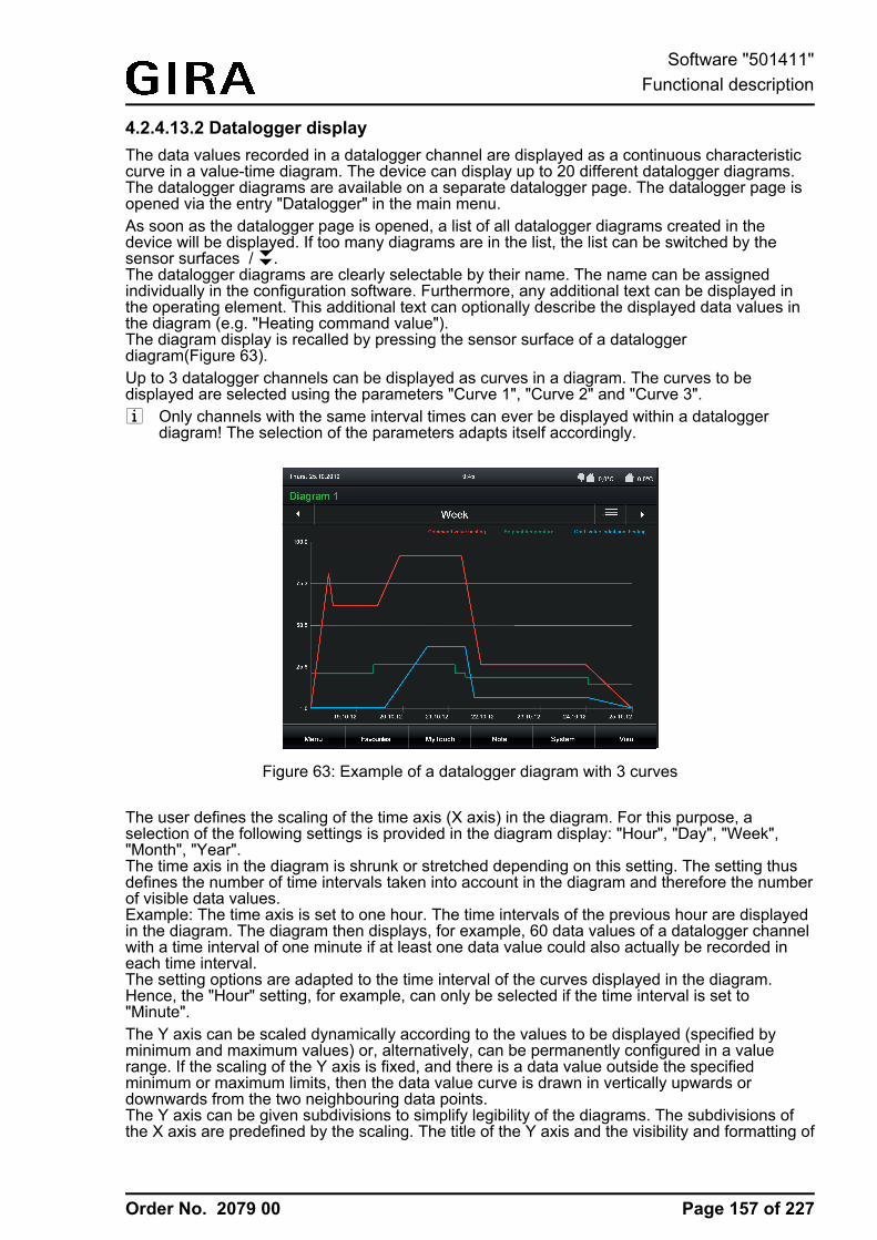
Order No. 2079 00
4.2.4.13.2 Datalogger displayThe data values recorded in a datalogger channel are displayed as a continuous characteristiccurve in a value-time diagram. The device can display up to 20 different datalogger diagrams.The datalogger diagrams are available on a separate datalogger page. The datalogger page isopened via the entry "Datalogger" in the main menu.As soon as the datalogger page is opened, a list of all datalogger diagrams created in thedevice will be displayed. If too many diagrams are in the list, the list can be switched by thesensor surfaces / ®.The datalogger diagrams are clearly selectable by their name. The name can be assignedindividually in the configuration software. Furthermore, any additional text can be displayed inthe operating element. This additional text can optionally describe the displayed data values inthe diagram (e.g. "Heating command value").The diagram display is recalled by pressing the sensor surface of a dataloggerdiagram(Figure 63).Up to 3 datalogger channels can be displayed as curves in a diagram. The curves to bedisplayed are selected using the parameters "Curve 1", "Curve 2" and "Curve 3".i Only channels with the same interval times can ever be displayed within a datalogger
diagram! The selection of the parameters adapts itself accordingly.
Figure 63: Example of a datalogger diagram with 3 curves
The user defines the scaling of the time axis (X axis) in the diagram. For this purpose, aselection of the following settings is provided in the diagram display: "Hour", "Day", "Week","Month", "Year".The time axis in the diagram is shrunk or stretched depending on this setting. The setting thusdefines the number of time intervals taken into account in the diagram and therefore the numberof visible data values.Example: The time axis is set to one hour. The time intervals of the previous hour are displayedin the diagram. The diagram then displays, for example, 60 data values of a datalogger channelwith a time interval of one minute if at least one data value could also actually be recorded ineach time interval.The setting options are adapted to the time interval of the curves displayed in the diagram.Hence, the "Hour" setting, for example, can only be selected if the time interval is set to"Minute".The Y axis can be scaled dynamically according to the values to be displayed (specified byminimum and maximum values) or, alternatively, can be permanently configured in a valuerange. If the scaling of the Y axis is fixed, and there is a data value outside the specifiedminimum or maximum limits, then the data value curve is drawn in vertically upwards ordownwards from the two neighbouring data points.The Y axis can be given subdivisions to simplify legibility of the diagrams. The subdivisions ofthe X axis are predefined by the scaling. The title of the Y axis and the visibility and formatting of
Page 157 of 227
Software "501411"Functional description
Order No. 2079 00
the axis labelling can also be configured. In addition, the heading of the diagram and the namesof the curves are defined in the parameterisation."Gain" and "Offset" can be added to the measured values of a channel to allow the option ofmodification of the desired measured value ranges in the diagram. In addition, it is necessary tospecify in the parameters of a datalogger diagram which data value is to be displayed in thediagram as the "curve type" (maximum value, minimum value, average or differential value).
i Within a diagram, the characteristic curve created from the data values runs from right tolevel parallel to the time axis.
i If, within a period of time, no telegram could be received and evaluated, then thecorresponding interval is considered "invalid". The characteristic curve is thus interrupted inthe value-time diagram of the on-screen display.
i In a diagram, the values of a datalogger channel are displayed without reformatting in theway they were received in the data telegram from the bus, providing that no gain or offset isspecified in the configuration of the curve. As a result, a data value, for example, receivedin the format DPT 5.001 (1 byte value) in a value range of 0...255 can be displayed in thediagram. If, in this example, percentage values should be displayed(e.g. command values), the data values can be reformatted by the reinforcement. In such acase, a 1 byte data value (0...255) with a gain of "0.392" can be converted to a percentagedata value (0...100 %). This gain should then be entered in the parameter of the samename of the curve concerned in the configuration software.An offset causes a shift of the appropriate curve upwards on the Y axis (positive offset) ordownwards (negative offset).
Page 158 of 227
Software "501411"Functional description
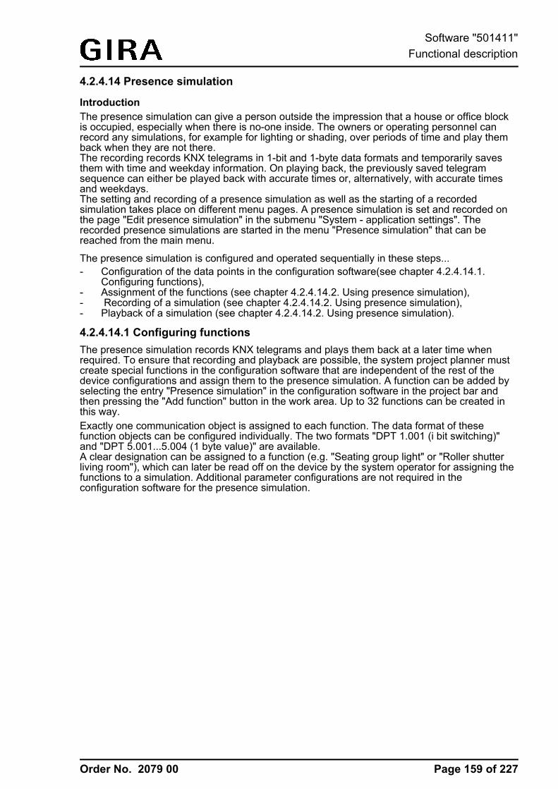
Order No. 2079 00
4.2.4.14 Presence simulation
IntroductionThe presence simulation can give a person outside the impression that a house or office blockis occupied, especially when there is no-one inside. The owners or operating personnel canrecord any simulations, for example for lighting or shading, over periods of time and play themback when they are not there.The recording records KNX telegrams in 1-bit and 1-byte data formats and temporarily savesthem with time and weekday information. On playing back, the previously saved telegramsequence can either be played back with accurate times or, alternatively, with accurate timesand weekdays.The setting and recording of a presence simulation as well as the starting of a recordedsimulation takes place on different menu pages. A presence simulation is set and recorded onthe page "Edit presence simulation" in the submenu "System - application settings". Therecorded presence simulations are started in the menu "Presence simulation" that can bereached from the main menu.
The presence simulation is configured and operated sequentially in these steps...- Configuration of the data points in the configuration software(see chapter 4.2.4.14.1.
Configuring functions),- Assignment of the functions (see chapter 4.2.4.14.2. Using presence simulation),- Recording of a simulation (see chapter 4.2.4.14.2. Using presence simulation),- Playback of a simulation (see chapter 4.2.4.14.2. Using presence simulation).
4.2.4.14.1 Configuring functionsThe presence simulation records KNX telegrams and plays them back at a later time whenrequired. To ensure that recording and playback are possible, the system project planner mustcreate special functions in the configuration software that are independent of the rest of thedevice configurations and assign them to the presence simulation. A function can be added byselecting the entry "Presence simulation" in the configuration software in the project bar andthen pressing the "Add function" button in the work area. Up to 32 functions can be created inthis way.Exactly one communication object is assigned to each function. The data format of thesefunction objects can be configured individually. The two formats "DPT 1.001 (i bit switching)"and "DPT 5.001...5.004 (1 byte value)" are available.A clear designation can be assigned to a function (e.g. "Seating group light" or "Roller shutterliving room"), which can later be read off on the device by the system operator for assigning thefunctions to a simulation. Additional parameter configurations are not required in theconfiguration software for the presence simulation.
Page 159 of 227
Software "501411"Functional description
Order No. 2079 00
4.2.4.14.2 Using presence simulation
Select functionsBefore a simulation can be recorded, the functions must be selected which are to be integratedin the presence simulation. Functions must already be created in the device configuration andlinked with group addresses beforehand so that they can be assigned to a simulation. The term"Functions" is used alternatively here for the name "Objects", since the switching or valueobjects configured in the configuration activate specific functions, such as switching lights orcontrolling a shading situation.It is possible to select the functions of a simulation when the "Functions" dialog menu in the"Edit presence simulation" menu is opened (Figure 64). A list of all configured functions (1...32)of the presence simulation then appears. The corresponding function can be activated and thusadded to the simulation by pressing the sensor surface of a function. In this way, up to 15functions can be assigned to a simulation.The selection must then be confirmed by pressing the sensor surface "OK". The functionselection is discarded by pressing the sensor surface "ESC".
Figure 64: Example of a dialog menu for selecting functions
i The "Start" button will not be activated until a function is added for a simulation. It isdisplayed in grey and the text "not ready" appears. If functions have already been defined,the text "Start" will be displayed indicating the recording of a presence simulation. It is firstpossible to play back the simulation in the menu "Presence simulation" after a successfulrecording.
i Saving takes place as soon as one telegram at least has been recorded.i If the function selection is changed and resaved after a simulation has been recorded, then
the previous recording is deleted. The operator must then record a new simulation (seenext section).
Recording a telegram sequenceAfter the operator has selected the functions of the presence simulation, the telegram sequencecan be recorded. For this, the operator must first specify a maximum recording period in days. Asimulation recording usually takes place independently in the background. The length of therecording period is used to specify when the simulation recording stops automatically afterstarting. A recording can also be stopped manually at any time regardless of this.The duration of the recording period is entered after tapping the sensor surface "Start" in the"Duration" dialog window (Figure 65). Time periods from 1...7 days can be configured. A day is
Page 160 of 227
Software "501411"Functional description
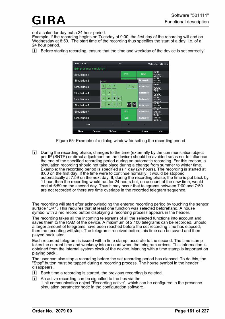
Order No. 2079 00
not a calendar day but a 24 hour period.Example: if the recording begins on Tuesday at 9:00, the first day of the recording will end onWednesday at 8:59. The start time of the recording thus specifies the start of a day, i.e. of a24 hour period.i Before starting recording, ensure that the time and weekday of the device is set correctly!
Figure 65: Example of a dialog window for setting the recording period
i During the recording phase, changes to the time (externally by the communication objectper IP (SNTP) or direct adjustment on the device) should be avoided so as not to influencethe end of the specified recording period during an automatic recording. For this reason, asimulation recording should not take place during a change from summer to winter time.Example: the recording period is specified as 1 day (24 hours). The recording is started at8:00 on the first day. If the time were to continue normally, it would be stoppedautomatically at 7:59 on the next day. If, during the recording phase, the time is put back by1 hour, then the recording would run for 24 hours but, on account of the new time, wouldend at 6:59 on the second day. Thus it may occur that telegrams between 7:00 and 7:59are not recorded or there are time overlaps in the recorded telegram sequence.
The recording will start after acknowledging the entered recording period by touching the sensorsurface "OK" . This requires that at least one function was selected beforehand. A housesymbol with a red record button displaying a recording process appears in the header.The recording takes all the incoming telegrams of all the selected functions into account andsaves them to the RAM of the device. A maximum of 2,100 telegrams can be recorded. Shoulda larger amount of telegrams have been reached before the set recording time has elapsed,then the recording will stop. The telegrams received before this time can be saved and thenplayed back later.Each recorded telegram is issued with a time stamp, accurate to the second. The time stamptakes the current time and weekday into account when the telegram arrives. This information isobtained from the internal system clock of the device. Marking with a time stamp is important onplaying back .The user can also stop a recording before the set recording period has elapsed. To do this, the"Stop" button must be tapped during a recording process. The house symbol in the headerdisappears.i Each time a recording is started, the previous recording is deleted.i An active recording can be signalled to the bus via the
1-bit communication object "Recording active", which can be configured in the presencesimulation parameter node in the configuration software.
Page 161 of 227
Software "501411"Functional description
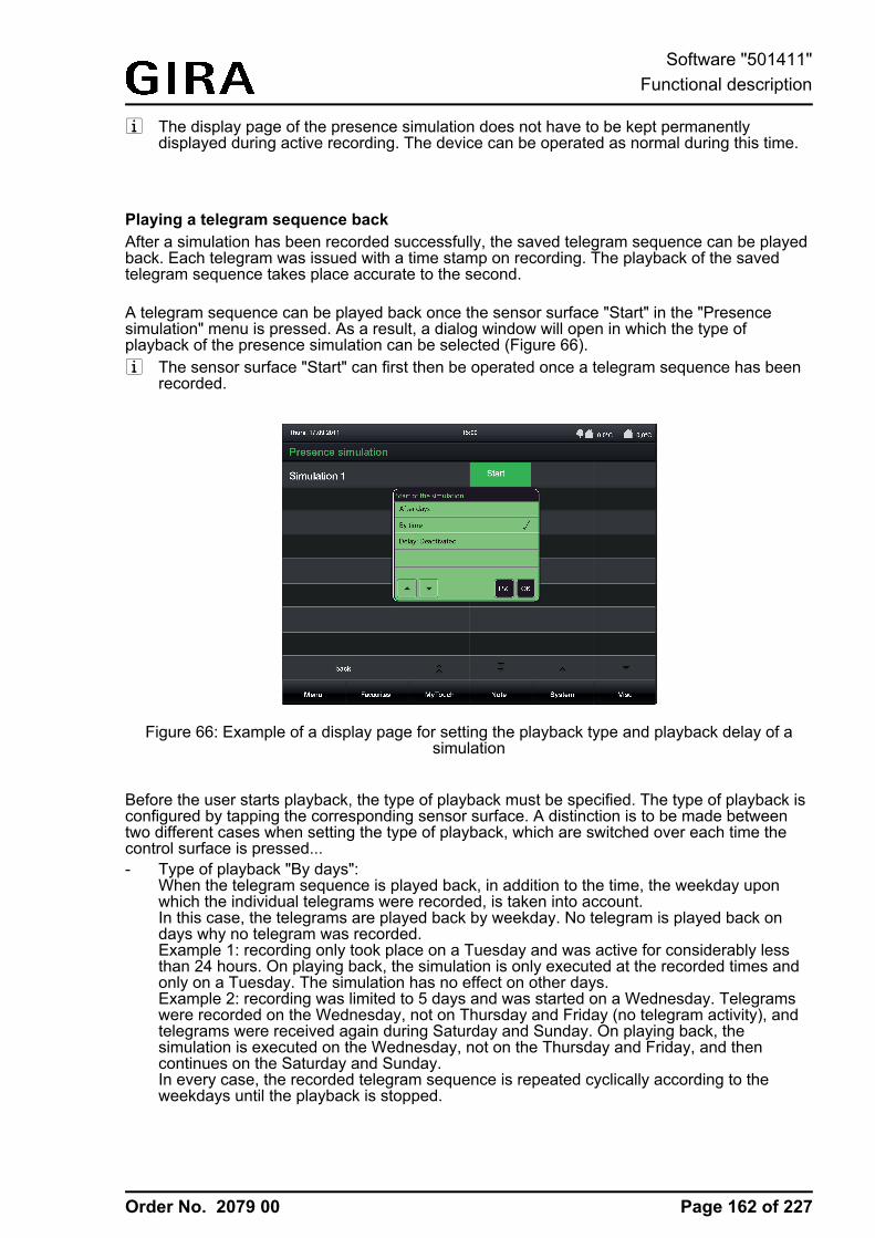
Order No. 2079 00
i The display page of the presence simulation does not have to be kept permanentlydisplayed during active recording. The device can be operated as normal during this time.
Playing a telegram sequence backAfter a simulation has been recorded successfully, the saved telegram sequence can be playedback. Each telegram was issued with a time stamp on recording. The playback of the savedtelegram sequence takes place accurate to the second.
A telegram sequence can be played back once the sensor surface "Start" in the "Presencesimulation" menu is pressed. As a result, a dialog window will open in which the type ofplayback of the presence simulation can be selected (Figure 66).i The sensor surface "Start" can first then be operated once a telegram sequence has been
recorded.
Figure 66: Example of a display page for setting the playback type and playback delay of asimulation
Before the user starts playback, the type of playback must be specified. The type of playback isconfigured by tapping the corresponding sensor surface. A distinction is to be made betweentwo different cases when setting the type of playback, which are switched over each time thecontrol surface is pressed...- Type of playback "By days":
When the telegram sequence is played back, in addition to the time, the weekday uponwhich the individual telegrams were recorded, is taken into account.In this case, the telegrams are played back by weekday. No telegram is played back ondays why no telegram was recorded.Example 1: recording only took place on a Tuesday and was active for considerably lessthan 24 hours. On playing back, the simulation is only executed at the recorded times andonly on a Tuesday. The simulation has no effect on other days.Example 2: recording was limited to 5 days and was started on a Wednesday. Telegramswere recorded on the Wednesday, not on Thursday and Friday (no telegram activity), andtelegrams were received again during Saturday and Sunday. On playing back, thesimulation is executed on the Wednesday, not on the Thursday and Friday, and thencontinues on the Saturday and Sunday.In every case, the recorded telegram sequence is repeated cyclically according to theweekdays until the playback is stopped.
Page 162 of 227
Software "501411"Functional description
Order No. 2079 00
- Type of playback "By time":When the telegram sequence is played back, only the time of the individual telegrams istaken into account. The weekday is ignored.The previously recorded telegram sequence is repeated cyclically until the playback isstopped.
The start of a playback of a telegram sequence can optionally be delayed for up to one day. Todo this, a time in hours (0...24) must be specified by pressing the sensor surface "Delay" via theon-screen keyboard. The setting "0" deactivates the delay time. In this case, the playback startsimmediately after the start command. The delay time only has an effect on the start time of thesimulation (like delayed tapping of the "Simulation" control surface) but not on the saved timestamps of the telegrams.The time of an elapsing delay is displayed in the status text of the control surface (B). Thisallows the remaining time to be read clearly up until the actual starting process.The delay time is advisable, for instance, if the start of the simulation should first occur when itcan be assumed that no more persons are in the building (e.g. before a weekend or companyholiday).After acknowledging the set type of playback by pressing the sensor surface "OK", the presencesimulation will start automatically, possibly with a set delay. A house symbol with a start buttonappears in the header.The playback can be cancelled at any time by tapping the sensor surface "Stop". In addition,playback of the presence simulation can be started and stopped using the"Start/stop playback" 1 bit communication object.i Stopping a playback causes the delay time to stop. This is restarted completely once the
start command is given again.
i The previously recorded telegrams of the simulation are worked through chronologically.The time of processing depends on the starting time of the simulation. If, for example, therecording period began at 8:00 but playback is not started until 9:00, then only thosetelegrams will be transmitted which were recorded at or after 9:00. Telegrams before thistime are only taken into account in the next cycle (only time or time/weekday-dependent).During the playback of a recording period, the telegrams are only transmitted once within acycle. If, during playback, the time of the device is put back, then previously transmittedtelegrams of a cycle will not be transmitted anew. If the time is put forward, then the devicedetects which telegrams were skipped, and then transmits the telegrams in one go, thussynchronising the telegram sequence with the current time.The same thing happens if, during the recording phase, the time was put back, for exampleon changing from summer to winter time. In this case, the panel checks during playback tosee if the telegram following the current one is more recent in the recording. If this is not thecase, due to the change in time in the recording, then the older telegrams are transmittedimmediately until the time stamp matches again.
i Active playback can be signalled to the bus using the1-bit communication object "Playback active", which can be configured in the presencesimulation parameters in the configuration software.
i Simulation playback only ever takes place using the group addresses of the functionobjects to be sent.
i The display page of the presence simulation does not have to be kept displayed duringactive playback. The device can be operated as normal during this time.
Resetting simulationAn entire simulation can be reset if required. At the same time, all function assignments and thesaved telegrams are deleted. Resetting is executed when the sensor surface in the dialogwindow "Edit simulation 1" is pressed .
Page 163 of 227
Software "501411"Functional description
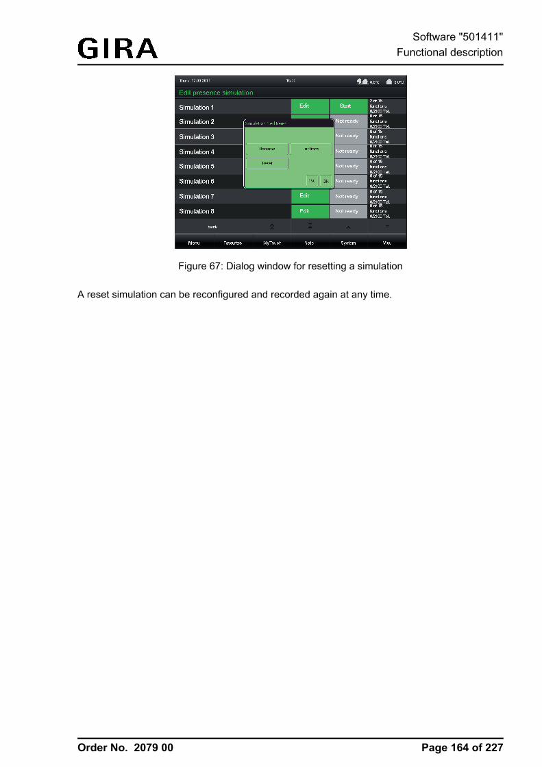
Order No. 2079 00
Figure 67: Dialog window for resetting a simulation
A reset simulation can be reconfigured and recorded again at any time.
Page 164 of 227
Software "501411"Functional description
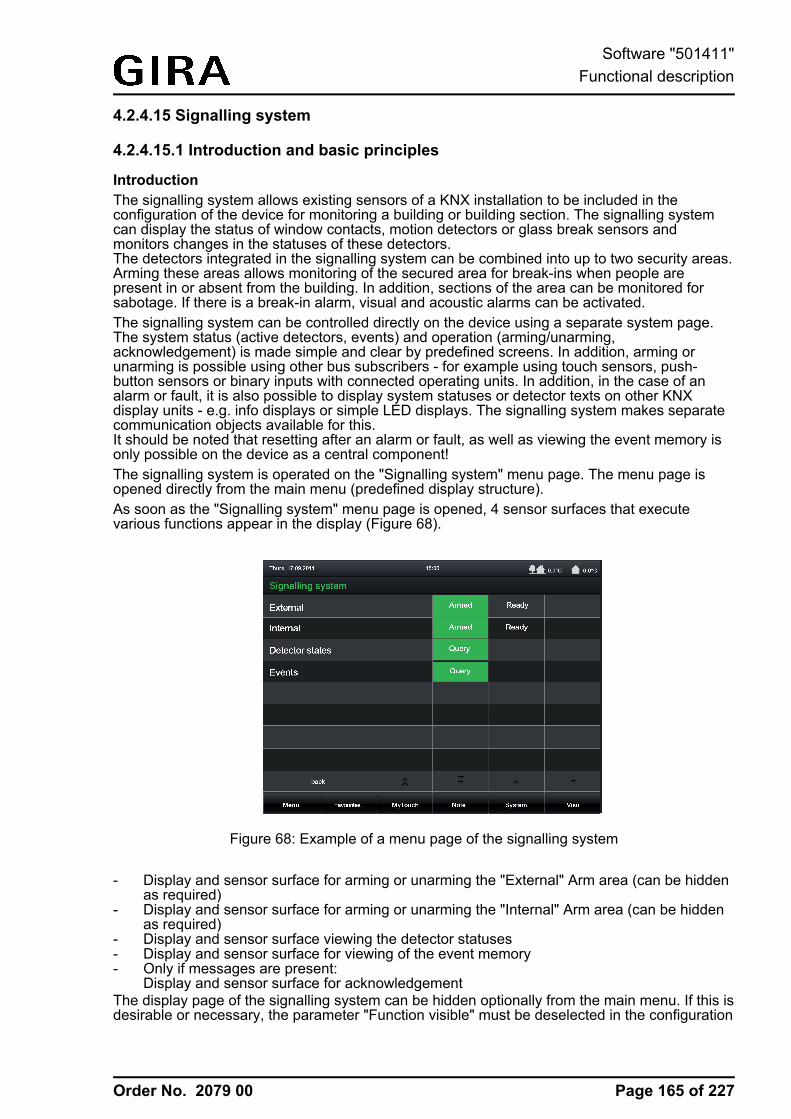
Order No. 2079 00
4.2.4.15 Signalling system
4.2.4.15.1 Introduction and basic principles
IntroductionThe signalling system allows existing sensors of a KNX installation to be included in theconfiguration of the device for monitoring a building or building section. The signalling systemcan display the status of window contacts, motion detectors or glass break sensors andmonitors changes in the statuses of these detectors.The detectors integrated in the signalling system can be combined into up to two security areas.Arming these areas allows monitoring of the secured area for break-ins when people arepresent in or absent from the building. In addition, sections of the area can be monitored forsabotage. If there is a break-in alarm, visual and acoustic alarms can be activated.The signalling system can be controlled directly on the device using a separate system page.The system status (active detectors, events) and operation (arming/unarming,acknowledgement) is made simple and clear by predefined screens. In addition, arming orunarming is possible using other bus subscribers - for example using touch sensors, push-button sensors or binary inputs with connected operating units. In addition, in the case of analarm or fault, it is also possible to display system statuses or detector texts on other KNXdisplay units - e.g. info displays or simple LED displays. The signalling system makes separatecommunication objects available for this.It should be noted that resetting after an alarm or fault, as well as viewing the event memory isonly possible on the device as a central component!The signalling system is operated on the "Signalling system" menu page. The menu page isopened directly from the main menu (predefined display structure).As soon as the "Signalling system" menu page is opened, 4 sensor surfaces that executevarious functions appear in the display (Figure 68).
Figure 68: Example of a menu page of the signalling system
- Display and sensor surface for arming or unarming the "External" Arm area (can be hiddenas required)
- Display and sensor surface for arming or unarming the "Internal" Arm area (can be hiddenas required)
- Display and sensor surface viewing the detector statuses- Display and sensor surface for viewing of the event memory- Only if messages are present:
Display and sensor surface for acknowledgementThe display page of the signalling system can be hidden optionally from the main menu. If this isdesirable or necessary, the parameter "Function visible" must be deselected in the configuration
Page 165 of 227
Software "501411"Functional description
Order No. 2079 00
software in the global settings of the signalling system. The signalling system is then no longeraccessible via the predefined menu structures of the visualisation. It can then only be accessedby means of internal open pages and operated via the communication objects.i As a function component of the device, the signalling system is not a complete alarm
system. For example, if the main or bus power supply fails, uninterrupted operation is notguaranteed. In addition, no signal encoders or transmission devices can be directlyconnected to the system, meaning that there is no opportunity to monitor these elements.The device's signalling system is also not VDS-certified.If such functions or characteristics are required, a suitable alarm centre must serve as areplacement.
i The display page of the signalling system can be protected from access by unauthorisedpersons by means of its own password. If this is desired, the password protection of thedisplay page must be activated in the configuration software.
Security areas and configurationA security area is an area of the signalling system, which secures specific building sectionssuch as individual rooms, building wings or facade areas and monitors them for break-ins. In thesecurity areas, detectors are those components which allow such monitoring. These detectorscould be magnetic contacts on windows or doors, motion detectors on walls or ceilings ininteriors as well as glass break sensors. Detectors can be connected to the KNX via suitablecomponents (button interfaces, binary inputs, etc.) or, depending on the device version, beconnected to the KNX directly.Security areas can be activated and deactivated, i.e. armed and unarmed. Arming andunarming takes places either directly on the device or using the external KNX switching units.i External switching units are components such as keyswitches, transponder units, code
keypads or block locks. In many cases, such units are intended for use in alarm orsignalling systems and, for this reason, can monitor for sabotage. Simple installationbuttons or KNX push button sensors can also easily be used as switching units. However,these do not provide any protection against unauthorised sabotage access. For thisreason, button sensors are often attached within a building to be protected, for example toactivate the external skin monitoring ("internal arming").External switching units can be coupled to the device's signalling system using separate1-bit objects. The sabotage contacts of the switching unit can be included using the"Sabotage" detector input (see page 171).
The signalling system makes a distinction between security areas, the interior and the externalskin. This distinction allows separate monitoring and arming of different building sectionsdepending on whether authorised people are in them or not. During the configuration of thesignalling system in the configuration software, created detectors are assigned to the securityareas."External skin" security area:The external skin separates the indoor area of a object to be secured, from the external area.Detectors integrated in the external skin can, for example, detect unauthorised access orsabotage to the house or garden door, to the building windows and to the garage door. In thesecases, suitable detectors are often magnetic contacts or glass break sensors.The external skin can be armed separately. Arming usually take place using a switching unitlocated within the building (e.g. control surface on the device, button sensor). In this case, thereare authorised people in the building. Only monitoring of the external skin takes place. Only theinternal siren is activated when there is an alarm. This status is called "internally armed".
Page 166 of 227
Software "501411"Functional description
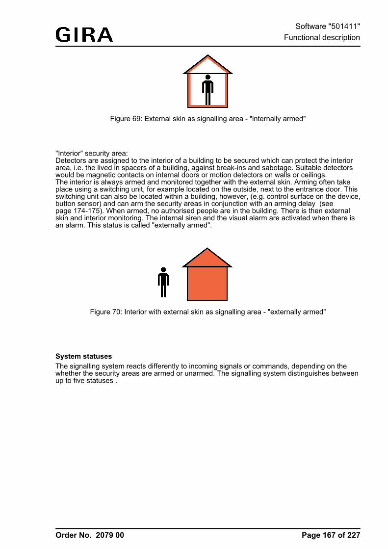
Order No. 2079 00
Figure 69: External skin as signalling area - "internally armed"
"Interior" security area:Detectors are assigned to the interior of a building to be secured which can protect the interiorarea, i.e. the lived in spacers of a building, against break-ins and sabotage. Suitable detectorswould be magnetic contacts on internal doors or motion detectors on walls or ceilings.The interior is always armed and monitored together with the external skin. Arming often takeplace using a switching unit, for example located on the outside, next to the entrance door. Thisswitching unit can also be located within a building, however, (e.g. control surface on the device,button sensor) and can arm the security areas in conjunction with an arming delay (seepage 174-175). When armed, no authorised people are in the building. There is then externalskin and interior monitoring. The internal siren and the visual alarm are activated when there isan alarm. This status is called "externally armed".
Figure 70: Interior with external skin as signalling area - "externally armed"
System statusesThe signalling system reacts differently to incoming signals or commands, depending on thewhether the security areas are armed or unarmed. The signalling system distinguishes betweenup to five statuses .
Page 167 of 227
Software "501411"Functional description
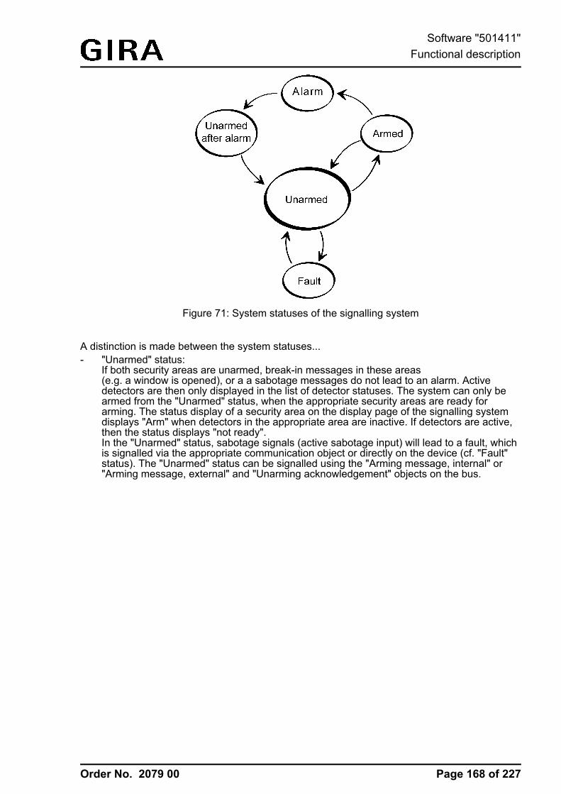
Order No. 2079 00
Figure 71: System statuses of the signalling system
A distinction is made between the system statuses...- "Unarmed" status:
If both security areas are unarmed, break-in messages in these areas(e.g. a window is opened), or a a sabotage messages do not lead to an alarm. Activedetectors are then only displayed in the list of detector statuses. The system can only bearmed from the "Unarmed" status, when the appropriate security areas are ready forarming. The status display of a security area on the display page of the signalling systemdisplays "Arm" when detectors in the appropriate area are inactive. If detectors are active,then the status displays "not ready".In the "Unarmed" status, sabotage signals (active sabotage input) will lead to a fault, whichis signalled via the appropriate communication object or directly on the device (cf. "Fault"status). The "Unarmed" status can be signalled using the "Arming message, internal" or"Arming message, external" and "Unarming acknowledgement" objects on the bus.
Page 168 of 227
Software "501411"Functional description
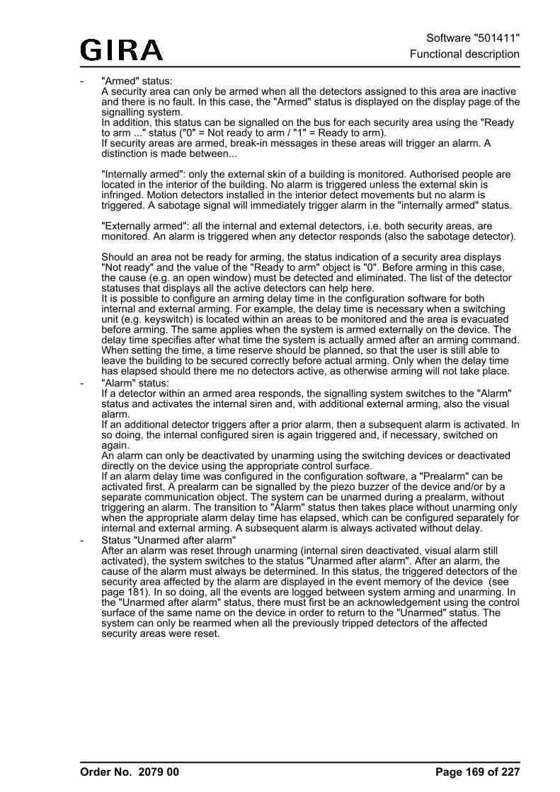
Order No. 2079 00
- "Armed" status:A security area can only be armed when all the detectors assigned to this area are inactiveand there is no fault. In this case, the "Armed" status is displayed on the display page of thesignalling system.In addition, this status can be signalled on the bus for each security area using the "Readyto arm ..." status ("0" = Not ready to arm / "1" = Ready to arm).If security areas are armed, break-in messages in these areas will trigger an alarm. Adistinction is made between...
"Internally armed": only the external skin of a building is monitored. Authorised people arelocated in the interior of the building. No alarm is triggered unless the external skin isinfringed. Motion detectors installed in the interior detect movements but no alarm istriggered. A sabotage signal will immediately trigger alarm in the "internally armed" status.
"Externally armed": all the internal and external detectors, i.e. both security areas, aremonitored. An alarm is triggered when any detector responds (also the sabotage detector).
Should an area not be ready for arming, the status indication of a security area displays"Not ready" and the value of the "Ready to arm" object is "0". Before arming in this case,the cause (e.g. an open window) must be detected and eliminated. The list of the detectorstatuses that displays all the active detectors can help here.It is possible to configure an arming delay time in the configuration software for bothinternal and external arming. For example, the delay time is necessary when a switchingunit (e.g. keyswitch) is located within an areas to be monitored and the area is evacuatedbefore arming. The same applies when the system is armed externally on the device. Thedelay time specifies after what time the system is actually armed after an arming command.When setting the time, a time reserve should be planned, so that the user is still able toleave the building to be secured correctly before actual arming. Only when the delay timehas elapsed should there me no detectors active, as otherwise arming will not take place.
- "Alarm" status:If a detector within an armed area responds, the signalling system switches to the "Alarm"status and activates the internal siren and, with additional external arming, also the visualalarm.If an additional detector triggers after a prior alarm, then a subsequent alarm is activated. Inso doing, the internal configured siren is again triggered and, if necessary, switched onagain.An alarm can only be deactivated by unarming using the switching devices or deactivateddirectly on the device using the appropriate control surface.If an alarm delay time was configured in the configuration software, a "Prealarm" can beactivated first. A prealarm can be signalled by the piezo buzzer of the device and/or by aseparate communication object. The system can be unarmed during a prealarm, withouttriggering an alarm. The transition to "Alarm" status then takes place without unarming onlywhen the appropriate alarm delay time has elapsed, which can be configured separately forinternal and external arming. A subsequent alarm is always activated without delay.
- Status "Unarmed after alarm"After an alarm was reset through unarming (internal siren deactivated, visual alarm stillactivated), the system switches to the status "Unarmed after alarm". After an alarm, thecause of the alarm must always be determined. In this status, the triggered detectors of thesecurity area affected by the alarm are displayed in the event memory of the device (seepage 181). In so doing, all the events are logged between system arming and unarming. Inthe "Unarmed after alarm" status, there must first be an acknowledgement using the controlsurface of the same name on the device in order to return to the "Unarmed" status. Thesystem can only be rearmed when all the previously tripped detectors of the affectedsecurity areas were reset.
Page 169 of 227
Software "501411"Functional description
Order No. 2079 00
- "Fault" status:The system switches to the "Fault" status when the sabotage detector has tripped or if,during detector monitoring, at least one missing detector was detected. A fault restricts thefunction of the signalling system to such an extent that proper operation can no longer beguaranteed.If a fault results from the "Unarmed" status, then the system cannot be rearmed (statusdisplay on the device "Not ready"). In this case, the fault must be detected using the list ofdetector statuses and eliminated through acknowledgement .In the armed status, sabotage or a missing detector will immediately trigger an alarm. Inthis case, the system will only switch to the "Fault" status, after the alarm wasacknowledged.A fault message can be signalled to the bus using the "Fault" object.
Page 170 of 227
Software "501411"Functional description
Order No. 2079 00
4.2.4.15.2 Detector
Detector typesThe detectors of the signalling system are components that communicate via the KNX, whichmonitor a part of a building and signal a break-in or attempted break-in on the device.Commonly used detector types supported by the panel include magnetic contacts, glass breakdetectors and motion detectors. Special detectors can also be sabotage detectors, allowingsabotage or fault contacts of alarm encoders or switching devices (e.g. keyswitches) to beintegrated in the signalling system. Also, lock monitors, such as bolt switch contacts, aredetectors permitting a positive drive. This means that, for example, an area can only be armedwhen the front door is closed, i.e. the bolt switch contact is not active.A triggered detector allocated to a security area is immediately evaluated in the signallingsystem and, when armed, immediately leads to an alarm. When armed, all the detectors of asecurity area are evaluated after a delay after triggering, if an alarm delay time was configured(see page 177). When the system is unarmed, triggered detectors - such as an open window -prevent active arming of the affected detector areas.When the system is unarmed, a triggered sabotage detector causes a fault display and thusprevent arming of the system. When armed, an active sabotage detector immediately triggers asabotage alarm.The detector type (contact, movement, glass break) is defined for detectors of a security areaand configured separately in the configuration software for each detector (see next section). Thetype "sabotage detector" is specified automatically by the use of a separate communicationobject, independently of the security areas.
Creating detectors and detector communicationDuring configuration of the signalling system, detectors are added in the form of detector inputsin the configuration software "Interior security area" or "External skin security area".i Up to 40 detectors can be created.Each newly created detector can be assigned a name (identifier), which then clearly identifiesthe detector. This text should not exceed 14 characters (e.g. "Kitchen window", "Garage door"),since only a maximum of 14 characters are transmitted via the bus. The text is later displayedduring system operation in the list of detector statuses on the device screen or in the eventmemory if there is activity on the part of the detector, an alarm or a fault. Optionally, if there isan alarm, the detector text can be transmitted to the bus using separate14 byte communication objects.The detector type of a detector (contact, movement, glass break) is specified by the parameterof the same name of the detector input. The configured type only specifies the text display andthe symbol in the list of detector statuses (see next section) and has no further effect on thebehaviour of a detector.Each detector input has its own 1 bit communication object. The detectors are normallyconnected to the bus using suitable KNX components (such as binary inputs, button interfaces,etc.) and are thus connected to the detector system. The connection is made between thedetector object of the device and the object of the bus device to which the detector is connectedwith one group address each. For reasons of clarity and detector monitoring, only one singledetector may be connected to each detector object of the device (Detector -> Detector text ->Security area).In the configuration software, each detector input can be configured to different telegrampolarities, i.e. individual detectors can be active with a "1" telegram or a "0" telegram. Thepolarities configured in the signalling system must agree the edge parameters of the other bussubscribers. The following table clarifies the relationship between telegram polarity and edgeevaluation in the bus device of the detector.
Detector contacttype / Status
Edge reaction in thedetector bus device
Tele-gramvalue
Parameter in thesignalling system
Detectortriggers
Page 171 of 227
Software "501411"Functional description
Order No. 2079 00
NO contact /not actuated
Rising = ON 1 Active on 0 no
NC contact /Actuated
Falling = OFF 0 Active on 0 yes
NO contact /not actuated
Rising = OFF 0 Active on 1 no
NC contact /Actuated
Falling = ON 1 Active on 1 yes
NO contact /Not actuated
Falling = OFF 0 Active on 1 no
NO contact /Actuated
Rising = ON 1 Active on 1 yes
NO contact /Not actuated
Falling = ON 1 Active on 0 no
NO contact /Actuated
Rising = OFF 0 Active on 0 yes
Edge evaluation and telegram polarity of a detector telegram
Example 1: With the setting "Input active on 1" in the detector system, a glass break sensor mayonly trigger when there is a glass break and, in this case, the binary input, to which the glassbreak sensor is connected, transmits a "1" telegram to the bus.Example 2: With the window contact setting "Input active on 0-telegram" the contact detects a0-telegram when the window is open. If the window is closed, a 1-telegram must be sent once inorder to set the detector to inactive.The sabotage detector must not be created specially. The sabotage input is createdindependently of the security areas in the view of the communication objects of the signallingsystem as standard and can be connected to a group address. A fault triggered by a sabotageinput has a global effect on all the areas of the signalling system and requires specialacknowledgement (see page 180). In addition, the telegram polarity of the sabotage detectorinput is permanently predefined and cannot be set. The sabotage input of the signalling systemtriggers when a "1" telegram is received via the "Sabotage" object.
List of detector statusesAll active detectors are displayed in the list of detector statuses. The list is available commonlyfor the internal and external Arm areas and is recalled when the sensor surfaces "Detectorstatuses - Polls" are pressed. This makes it easy to detect which detectors are preventingsystem arming, for example. In addition, it is easy to see at any time which windows and doorsare open in the building.In addition, missing detectors and a triggered sabotage detector are entered in the detector list,allowing identification of the cause of a fault.
The following events are shown summarised in the list of detector statuses...- all active detectors of the respective security area
(Entry "<Detector name> + <Identification of the detector type>"Example: "Garden door open", "Glass break, kitchen window", "Movement in corridor"),
- An active sabotage detector ("Sabotage" entry),- All the missing detectors (Entry "<Detector name> + <Text, detector missing>"
Example: "front door detector missing").
Page 172 of 227
Software "501411"Functional description
Order No. 2079 00
i An entry only remains visible in the list of detector statuses until the appropriate detector isinactive again or has been detected as present.
Detector monitoringWithin a configurable monitoring period, the signalling system checks that the detectors createdin the security areas exist, i.e. whether they are still connected to the KNX and are functioning.For this purpose, the device sends a read telegram cyclically to the bus subscriber to be testedvia the group address connected to the detector input, e.g. to the transmitting object of a binaryinput. This bus subscriber must then send a response telegram back immediately to thesignalling system. This response must have reached the device within atimeframe of 2 seconds.If a contacted detector does not respond or responds after a delay, then the signalling systemwill check the appropriate detector a second and - if again no response is received - a third timewithin a short period. If, after the third query, the detector has still not responded, a fault (in the"Unarmed" status) or in alarm (in the "Armed" status) is triggered without further delay,depending on the system status.If a missing detector causes an alarm, additional missing detectors can trigger subsequentalarms.Each detector of a security area created in the configuration software is monitored in themanner described. The "Detector poll interval", which can be set in the parameters of thesignalling system, defines the time between two read telegrams, i.e. the time between twodetector tests. The signalling system polls all the created detector inputs in turn in this way.Example: poll interval: 10 s, 40 detectors have been created. -> A detector is polled every 10 s.After approx. 400 s, all the detectors have been tested. After this, the cycle test is continuedagain with the first detector.The signalling system tests detectors considered missing cyclically at brief intervals, in order tobe able to detect quickly whether or not the detector has reconnected. This is important forresetting a fault.i Detector monitoring does not take the sabotage input into account or the inputs for
arming/unarming the security areas.i After switching on the power supply of the device, or after a commissioning operation, the
signalling system quickly tests all the created detectors during device initialisation for theirexistence and, during the responses, evaluates the transmitted detector statuses (active /inactive). To avoid faults in the signalling system, all the detectors should already havebeen commissioned properly and be functional during device commissioning.In addition, the detector poll may cause a delay of maximum 40 s before the signallingsystem is ready for arming after a device reset (precondition: all the detectors are inactive).
i Care should always be taken to ensure that each detector input created in the configurationsoftware is also linked to a group address and that there is a communication partner in thebus. For detector monitoring to function, the "Read" flags must be set on the objects to betransmitted by the bus devices of the detectors.For each detector to be monitored, it is also important that the group addresses of thedetectors to be transmitted are clear, i.e. are not connected to any other transmitting bussubscriber. Each messages must have an independent connection to its own detector inputon the signalling system. Only then can it be ensured that only the contacted detectorresponds and that detector monitoring is clear.
Page 173 of 227
Software "501411"Functional description
Order No. 2079 00
4.2.4.15.3 Arming
Arming/unarming the security areasThe signalling system makes a distinction between security areas, the interior and the externalskin. This distinction allows separate monitoring and arming of different building sectionsdepending on whether authorised people are in them or not. For this reason, the device allowsinternal and external arming (see page 165-166).A security area can only be armed when all the detectors assigned to this area are inactive andthere is no fault in the system.Arming and unarming takes place either directly on the device or using KNX switching units,such as push-button sensors or push-button interfaces or key switches connected to binaryinputs. There are also two separate 1 bit communication objects available for arming the bus,one for internal arming and one for external arming. The telegram polarity of these objects isfixed: "1" = Arm / "0" = Unarm.Arming on the device is possible on the display page of the detector list using the "External" or"Internal" control surfaces, but only if the Arm areas are also ready for arming. Unarming takesplace via the same control surfaces. The device automatically switches the function (Arm /Unarm) according to the current system status. Local arming using the control surfaces can beprevented in the parameter configuration of the configuration software by hiding the controlsurfaces.
Arming without arming delay:The area to be armed must be ready for arming. On internal arming, the signalling system onlytests the external skin whilst on external arming, both the internal skin and the interior are testedfor arming readiness. The list of detector statuses helps the system operator to detect activedetectors which prevent arming readiness.Pressing the Arm control surface on the device or sending a "1" telegram to the "Internallyarmed" or "Externally armed" object causes the system to switch to the "Armed" statusimmediately.
Arming with an arming delay:Arming with an arming delay is often used when the switching device(e.g. the device or a button sensor) is installed in the secure area of the building. In this case,the system operator must be able to arm the system and still be able to leave the building intime. The arming delay can be configured separately, using the parameter of the same name inthe configuration software, for internal and external arming. Delay times of 0 to 255 s can beconfigured. The setting "0 s" (presetting) deactivates the arming delay for the appropriatearming operation. When setting the time, a time reserve should be planned, so that the user isstill able to leave the building to be secured correctly before actual arming.The delay time specifies after what time the system is actually armed after an arming command(turning of the keyswitch or pressing of the Arm area on the device). In so doing the signallingsystem only checks the arming readiness of the security areas after the delay time has elapsed.
Example: the system is to be armed externally on the device. For external arming, the systemoperator must leave the building. The front door is still open. Therefore, the device displays "notready". The operator can still carry out the arming command on the device. The signallingsystem starts the arming delay. Within this time, the owner leaves the building and locks thefront door. This makes the system ready for arming (no more detectors are active). When thedelay time has elapsed, the signalling system checks for the arming readiness system status. Ifit is ready, the system arms immediately.
Should, however, a detector still be active after the arming delay has elapsed, (e.g. front doornot closed or window opened), then arming does not take place! Here too, the list of detectorstatuses helps the system operator to detect active detectors which prevent arming readinessbefore setting the arming command. If the system does not arm after the delay time haselapsed, then no acknowledgement will take place either (see next section).
Page 174 of 227
Software "501411"Functional description
Order No. 2079 00
i An elapsing internal arming delay is unarmed when sending a 1-telegram to externalarming.
i An elapsing arming delay can be cancelled at any time by unarming.i Closing the pop-up window does not cancel the arming.
Unarming:In the "Armed" status, the system can be unarmed at any time. To do this, either the "Unarm"button must be pressed on the device or a switching device must be set to "Unarmed". Thesystem then switches to the "Unarmed" status immediately.If an alarm has occurred, then an Unarm command will reset the alarm (deactivation of theinternal siren) and switch to the "Unarmed after alarm" status. If there is an alarm delay, thenunarming within the elapsing delay time (prealarm) will prevent a alarm from being triggered(see page 177).
i The following always applies: if there is internal arming or an internal arming delay iselapsing, then external arming is not possible. Internal unarming must take place and then,if the system is ready to arm, external arming is possible. The reverse is true in likemanner.
i The signalling system only reacts to an arming or unarming command, when a systemstatus change is possible (Unarmed -> Armed / Armed -> Unarmed /Alarm -> Unarmed after alarm). Repeating telegrams (Armed -> Armed /Unarmed -> Unarmed - e.g. for KNX switching units with cyclic transmission) are ignoredby the signalling system.
i Arming or unarming is saved in the event memory along with the date and time (ifnecessary, only after the arming delay has elapsed) (see page 181).
i An internal arming is unarmed when sending a 1-telegram to external arming.
Signalling during arming/unarmingIn the case of external arming, the signalling system can confirm its status change "Unarmed" to"Armed" via the visual signal encoder output ("acknowledge"). This means that it is possible todetect clearly whether the system has responded to an arm command as required or not. This isparticularly important when the system is operated remotely - without seeing the device- or inthe case of an arming delay. The visual signal encoder will not give an acknowledgement onunarming. The signal encoder is also not controlled for internal arming.Whether the visual signal encoder is controlled in the case of external arming can be set in theconfiguration software using the parameter "Visual acknowledgement on external arming" in theparameters of the signalling system. This means that it is possible to switch visual feedback off.
In addition, various signals are available to signal the status of the signalling system. Thesesignals are 'run out' using separate KNX 1-bit objects and can be tapped.
The following objects can be configured in the parameters of the signalling system in theconfiguration software...- "Ready to arm, internal" and "Ready to arm, external":
These objects signal the readiness of the assigned security areas separately for internal orexternal arming. If the areas are ready for arming, the object value is "1". If they are notready, the object value is "0".When the system is armed (no matter whether internally or externally), both objects switchback to "0", irrespective of which status is displayed on the page of the signalling system onthe device.
- "Arming message, internal" and "Arming message, external":These objects signal whether the appropriate security areas are armed or unarmedseparately for internal or external arming. Signalling is static for the length of the status. Anobject value "1" means "Area(s) armed", whilst an object value "0" means"Area(s) unarmed". "Unarmed" is signalled in the system status "Unarmed after alarm".
Page 175 of 227
Software "501411"Functional description
Order No. 2079 00
- "Arming acknowledgement":This object dynamically signals successful internal or external arming for the length of the"Arming acknowledgement time" set in the configuration software. No distinction is madebetween the security areas. The object value switches to "1" as soon as the system hasarmed. The object value returns to "0" automatically when the arming acknowledgementhas elapsed. It is possible to cancel arming acknowledgement by unarming before thearming acknowledgement time has elapsed.
- "Unarming acknowledgement":This object dynamically signals successful internal or external unarming for the length ofthe "Unarming acknowledgement time" set in the configuration software. No distinction ismade between the security areas. The object value becomes "1" as soon as the systemhas unarmed (status change "Armed -> Unarmed" or "Alarm -> Unarmed after alarm").When the status changes from "Unarmed after alarm -> Unarmed", there is no unarmingacknowledgement. The object value returns to "0" automatically when the unarmingacknowledgement has elapsed. It is possible to cancel unarming acknowledgement byarming before the unarming acknowledgement time has elapsed.
i If, after an arming command (or after an arming delay has elapsed), the signalling systemdoes not arm, because the affected security areas are not ready to arm, there will be noacknowledgement. In this case, the dynamic object "Arming acknowledgement" and, in thecase of external arming, the visual signal encoder are not controlled (no negativeacknowledgement).
i To be able to distinguish between dynamic objects for arming and unarming, theacknowledgement times for "Arming" and "Unarming" should be of different lengths. Whenarming or unarming is repeated ("Armed" -> "Armed", "Unarmed" -> "Unarmed"), there isno retriggering of the dynamic signalling. This is only transmitted once on changing status.
Page 176 of 227
Software "501411"Functional description
Order No. 2079 00
4.2.4.15.4 Alarms
Activating and deactivating an alarmIf a detector within an armed area responds, or a sabotage detector triggers when armed or anydetector is found to be missing, the signalling system switches to the "Alarm" status andactivates the internal siren and, with additional external arming, also the visual alarm. For this,"1" telegrams are transmitted to the bus using the corresponding 1 bit communication objects. Inaddition, the device transmits a "1" telegram via the "Alarm" object. This allows any switchingfunction to be executed in the bus. In addition, the signalling system uses the14 byte object "Alarm detector text" to display the detector text of the detector which triggeredthe alarm.The internal siren is an alarm encoder activated for a set period of time. The system projectplanner must set the switching length of the internal siren in the configuration software.Switching times of 2 to 255 s are configurable. The signalling system automatically deactivatesthe internal siren when the switching time after the alarm is triggered has elapsed. The visualalarm (e.g. a flashing light on the exterior of the building) remains activated for the entire lengthof the alarm status (see "Alarm acknowledgement" section below).An alarm and the detector that causes the alarm are logged in the event memory of the device(see page 181).An active alarm can be switched off by unarming on the device or on a KNX switching unit. Inthis case, the device switches the internal siren off if it has not already been switched offautomatically after a period of time has elapsed, transmits a "0" telegram to the bus via the"Alarm" object and switches to the status "Unarmed after alarm". The visual alarm (for externalalarming) still remains switched on.i In the case of an alarm, the device can also send an e-mail with a predefined text,
providing that the Ethernet functionality of the device is used and an e-mail account wasconfigured. For this purpose, the "Alarm" object of the signalling system can be linked tothe object of an event e-mail of the device using an internal or external group address.
In the case of an alarm, a red triangle is displayed in the header of the screen. This symbol willalso remain visible even if an alarm - e.g. by a switching device - was disabled and the systemis in the status "Unarmed after alarm". This makes it possible for persons to easily recognise onthe device that an alarm is or was present irrespective of the visible display page. The symbol inthe header goes out after successful acknowledgement of an alarm.
Alarm delay / PrealarmAn alarm delay can optionally be configured for the internal and external arming. An alarm delayis often used when the switching device (e.g. the device or a button sensor) is installed in thesecure area of the building. In such cases, authorised people must be able to enter the securedbuilding area, meaning the status the switching device for unarming can only be reached after adelay.The alarm delay can be configured separately for internal and external arming using theparameter of the same name in the configuration software. Delay times of 0 to 255 s can beconfigured. The setting "0 s" (presetting) deactivates the alarm delay for the appropriate armingoperation.When an alarm time delay elapses during system operation, a dialog will window open in whichthe time delay is decremented to zero as with arming with arming delay.Furthermore, a "prealarm" can be activated. Depending on the parameter configuration, aprealarm is signalled by the piezo buzzer of the device and/or separate1-bit communication objects. During a prealarm, an authorised person can unarm the systemwithout triggering a "real" alarm. The transition to the "Alarm" status only takes place is thesystem is not unarmed during the prealarm.i A prealarm configured in the configuration software only functions if an alarm delay time of
more than 0 s has been configured. Otherwise the prealarm will not be executed duringsystem operation.
Page 177 of 227
Software "501411"Functional description
Order No. 2079 00
i An alarm due to a triggered sabotage detector or a missing detector is always executedwithout delay.
Subsequent alarmIf an additional detector of an armed security area triggers after a prior alarm, then asubsequent alarm is activated. In so doing, the internal configured siren is again triggered and, ifnecessary, switched on again. A detector which previously triggered an alarm cannot trigger asecond subsequent alarm.A subsequent alarm is always activated without delay, even with a planned alarm delay.A subsequent alarm and the detector causing it are logged in the event memory of the device(see page 181). In addition, the signalling system uses the 14-byte object "Alarm detector text"to display the detector text configured in the configuration software of the detector whichtriggered the alarm.
Alarm acknowledgement / "Unarmed after alarm"Each alarm must be acknowledged directly on the device. Without alarm acknowledgement, it isnot possible to switch to "Unarmed" status and thus additional arming. The system operator canacknowledge an alarm in the status "Unarmed after alarm".
Primarily, there are two methods of acknowledging an alarm...- Separate unarming + acknowledgement:
An active alarm (internal siren + "Alarm" object switched on) can - as described above - bedeactivated by unarming. The system switches the internal siren off if it has not alreadybeen switched off automatically, transmits a "0" telegram to the bus via the "Alarm" objectand an unarmed acknowledgement to the bus and switches to the status "Unarmed afteralarm". The visual alarm (for external alarming) remains switched on.In the "Unarmed after alarm" status, the operator can the inspect the event memory directlyon the device to see which detector triggered the alarm at which time. The alarm canusually then be confirmed by pressing the "Acknowledge" control surface on the device andthen reset completely. The system then switches the visual signal off (for external alarms)and then switches to the "Unarmed" status. In this case, there is no additional unarmingacknowledgement. The device transmits the text "No alarm" to the bus via the14 byte object "Alarm detector text".In the "Unarmed after alarm" status, the piezo buzzer of the device is controlled in order toalert the user to go to the device and acknowledge the alarm.
- Unarming by acknowledgement:An alarm can also be acknowledged directly without separate unarming and thus reset.Such behaviour is advisable, for example, when the internal siren set for a specific timeafter an alarm has already turned "quiet", i.e. need not be turned off, or the system isoperated directly on the device. For this purpose, the "Acknowledge" button can be pressedon the menu page of the device in the "Unarmed after alarm" status.With such operation, the signalling system completely deactivates the alarm andacknowledges it at the same time. Deactivating the alarm switches off the visual alarm (forexternal alarms) and the internal siren, if this has not already been switched offautomatically. In addition, the system transmits a "0" telegram via the "Alarm" object andthe text "No alarm" to the bus via the 14 byte object "Alarm detector text". The system thenimmediately switches to the status "Unarmed" without any separate unarmingacknowledgement. This type of operation does not set the status "Unarmed after alarm".Before or after the "Acknowledge" control surface is pressed, the system operator caninspect the event memory directly on the panel to see which detector triggered the alarm atwhich time.
Page 178 of 227
Software "501411"Functional description
Order No. 2079 00
i After an alarm has been acknowledged, the system automatically switches to the "Fault"status, if, for example, the sabotage input was the detector triggering the alarm. Thissubsequent fault must then be acknowledged separately on the device. The cause of thefault must have been eliminated for a fault message to be acknowledged (see page 180).
Page 179 of 227
Software "501411"Functional description
Order No. 2079 00
4.2.4.15.5 Fault
Cause of fault and fault behaviourThe signalling system switches to the "Fault" status when the sabotage detector has tripped inunarmed or if, during detector monitoring while unarmed, at least one missing detector wasdetected. If the system is armed, then these events will lead to an immediate alarm. In this case,the system will switch to the "Fault" status, when the alarm has been acknowledged.A fault restricts the function of the signalling system to such an extent that proper operation canno longer be guaranteed. A fault causes the system to no longer be armed for as long as thefault has not been eliminated. The list of detector statuses and the event memory can be usedto detect the cause of the fault and the time the fault was activated.If there is a system fault, the device transmits a "1" telegram via the "Fault" object. This allowsany switching function to be executed in the bus along with other signalling operations, e.g.using a transmission device. An e-mail, predefined in the device, can also be set by linking thisobject with an e-mail event.If the fault was triggered by a missing detector, the signalling system uses the14 byte object "Fault detector text" to display the detector text of the faulty detector. If severaldetectors are missing, then the detector text of the detector is transmitted which was mostrecently detected as missing.If the fault was triggered by the sabotage detector, then the test "Sabotage" is transmitted to thebus via the 14 byte object.The fault status continues to remain active, even if the cause of the fault has already beeneliminated. The status is first reset after the system operator has acknowledged the fault directlyon the device.
Acknowledgement of a fault messageA fault must always be acknowledged directly on the device. Without a fault acknowledgement,it is not possible to switch back to "Unarmed" status and thus additional arming. The cause ofthe fault must have been eliminated in order to be able to acknowledge a fault. This means thatthe sabotage detector may ot be active before acknowledgement, ad all the detectors of thesecurity areas must have been detected as existing. The list of detector statuses can be used todetect which detectors may be preventing the acknowledgement of a fault.After the operator has acknowledged a fault, the device uses the "Fault" object to transmit a"0" telegram and, via the 14 byte object "Fault detector text", the text "No fault" to the bus. Afterthis, the signalling is system is ready for operation again.i After an alarm has been acknowledged, the system automatically switches to the "Fault"
status, if, for example, the sabotage input was the detector triggering the alarm. Thissubsequent fault must then be acknowledged separately on the device in the mannerdescribed.
Page 180 of 227
Software "501411"Functional description
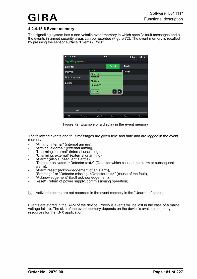
Order No. 2079 00
4.2.4.15.6 Event memoryThe signalling system has a non-volatile event memory in which specific fault messages and allthe events in armed security areas can be recorded (Figure 72). The event memory is recalledby pressing the sensor surface "Events - Polls".
Figure 72: Example of a display in the event memory
The following events and fault messages are given time and date and are logged in the eventmemory...- "Arming, internal" (internal arming),- "Arming, external" (external arming),- "Unarming, internal" (internal unarming),- "Unarming, external" (external unarming),- "Alarm" (also subsequent alarms),- "Detector activated: <Detector text>" (Detector which caused the alarm or subsequent
alarm),- "Alarm reset" (acknowledgement of an alarm),- "Sabotage" or "Detector missing: <Detector text>" (cause of the fault),- "Acknowledgement" (fault acknowledgement),- Reset" (return of power supply, commissioning operation).
i Active detectors are not recorded in the event memory in the "Unarmed" status.
Events are stored in the RAM of the device. Previous events will be lost in the case of a mainsvoltage failure. The size of the event memory depends on the device's available memoryresources for the KNX application.
Page 181 of 227
Software "501411"Functional description
Order No. 2079 00
4.2.4.15.7 Response to a device resetAfter switching on the mains power supply of the device or after a commissioning operation, thesignalling system always switches to the "Unarmed" status. Then the signalling system quicklytests all the created detectors of the security areas for their existence and ability to transmit and,during the responses, evaluates the transmitted detector statuses (active / inactive). Thischecks the security areas for their readiness to arm. During initialisation, the detector poll maycause a delay before the signalling system is ready for arming after a device reset (precondition:all the detectors are inactive). Should an active sabotage detector or a missing detector bedetected, then the system switches to the "Fault" status.Immediately after a reset, the signalling system generates a defined object status by setting allthe KNX communication objects to values that correspond to the set system status. The systemalso transmits telegrams.i The device, and thus also the signalling system, switches off when the mains power supply
fails. If the mains or bus power supply fails, uninterrupted operation is not guaranteed.Detector status, alarm and fault signals are not saved when the bus or mains power supplyfail.
Page 182 of 227
Software "501411"Functional description
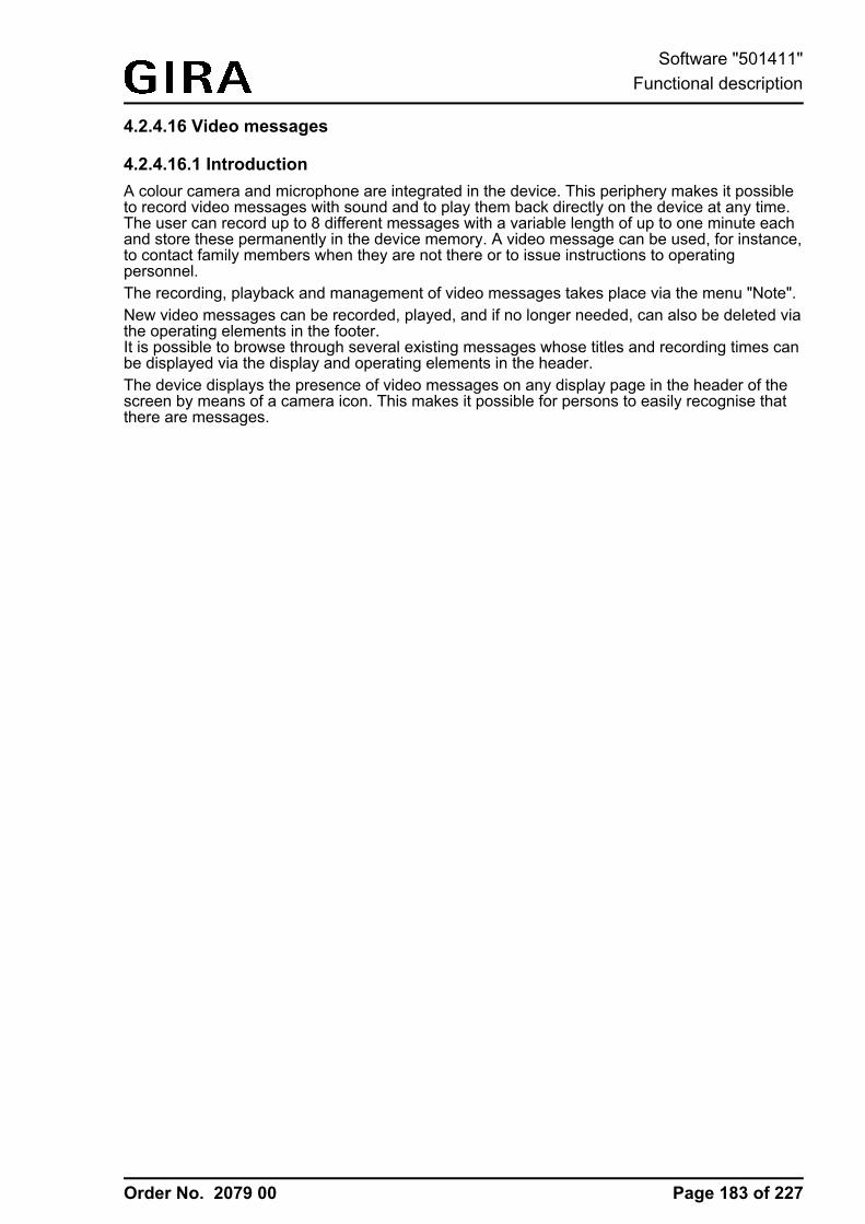
Order No. 2079 00
4.2.4.16 Video messages
4.2.4.16.1 IntroductionA colour camera and microphone are integrated in the device. This periphery makes it possibleto record video messages with sound and to play them back directly on the device at any time.The user can record up to 8 different messages with a variable length of up to one minute eachand store these permanently in the device memory. A video message can be used, for instance,to contact family members when they are not there or to issue instructions to operatingpersonnel.The recording, playback and management of video messages takes place via the menu "Note".New video messages can be recorded, played, and if no longer needed, can also be deleted viathe operating elements in the footer.It is possible to browse through several existing messages whose titles and recording times canbe displayed via the display and operating elements in the header.The device displays the presence of video messages on any display page in the header of thescreen by means of a camera icon. This makes it possible for persons to easily recognise thatthere are messages.
Page 183 of 227
Software "501411"Functional description
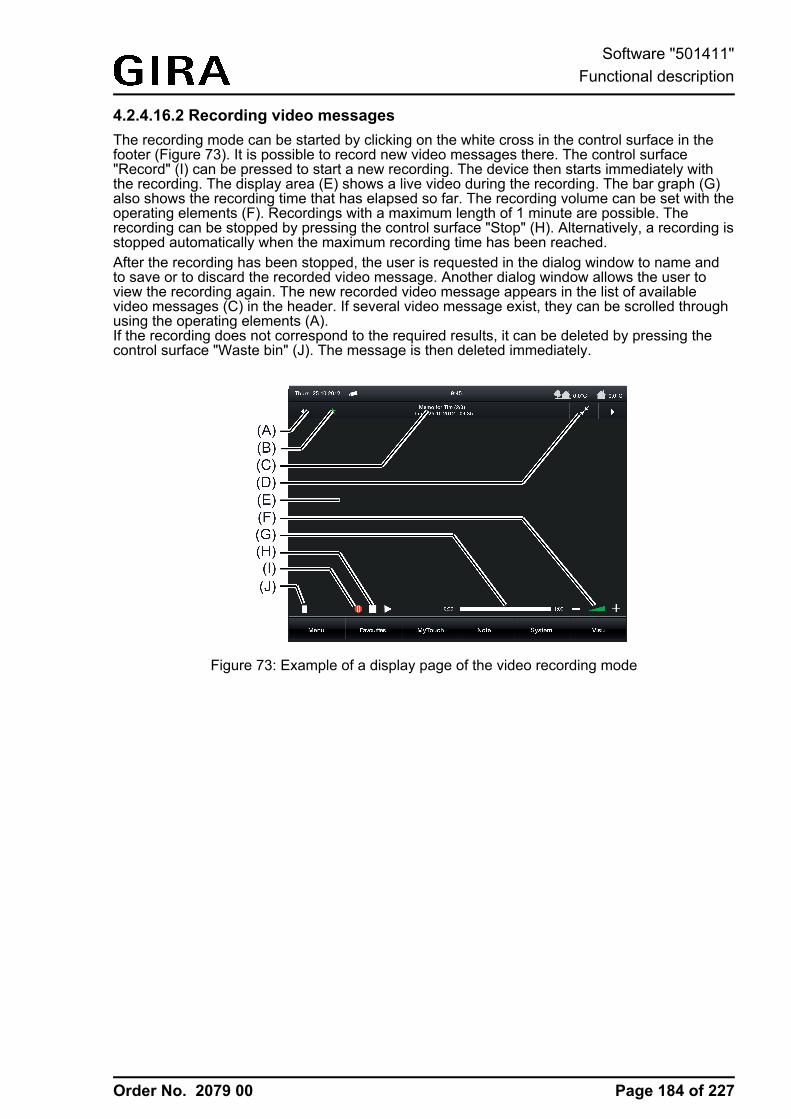
Order No. 2079 00
4.2.4.16.2 Recording video messagesThe recording mode can be started by clicking on the white cross in the control surface in thefooter (Figure 73). It is possible to record new video messages there. The control surface"Record" (I) can be pressed to start a new recording. The device then starts immediately withthe recording. The display area (E) shows a live video during the recording. The bar graph (G)also shows the recording time that has elapsed so far. The recording volume can be set with theoperating elements (F). Recordings with a maximum length of 1 minute are possible. Therecording can be stopped by pressing the control surface "Stop" (H). Alternatively, a recording isstopped automatically when the maximum recording time has been reached.After the recording has been stopped, the user is requested in the dialog window to name andto save or to discard the recorded video message. Another dialog window allows the user toview the recording again. The new recorded video message appears in the list of availablevideo messages (C) in the header. If several video message exist, they can be scrolled throughusing the operating elements (A).If the recording does not correspond to the required results, it can be deleted by pressing thecontrol surface "Waste bin" (J). The message is then deleted immediately.
Figure 73: Example of a display page of the video recording mode
Page 184 of 227
Software "501411"Functional description
Order No. 2079 00
4.2.4.16.3 Playing back video messagesThe camera symbol in the header of the display indicates that a video message that has not yetbeen viewed was saved. In the menu "Note", all saved messages are in the list of availablevideo messages (C). These can be scrolled through using the operating elements (A).Messages that have not yet been viewed are marked with a green asterisk (B) (Figure 74).The control surface "Start" (H) can be pressed to start a playback. The device then plays backthe recorded video message immediately in the display area (E). It is possible to vary thevolume of the audio playback using the operating elements (F).The playback can be stopped before the replay time has elapsed by pressing the controlsurface "Stop" (I). Alternatively, a playback is stopped automatically when the playback timecorresponds to the recording time.Once a video message is no longer used, it can be removed from the device memory bypressing the control surface "Waste bin" (J). This operation must then be confirmed. Themessage is then deleted permanently from the device memory. This frees a memory locationagain that can be used for recording a new video message.The playback mode can be exited by selecting another menu from the footer.
Figure 74: Example of a display page of the video playback mode
Page 185 of 227
Software "501411"Functional description
Order No. 2079 00
4.2.4.17 Standby behaviourThe device has a mains voltage terminal for power supply to the device electronics. The KNXfunction part (BCU) is functional as long as mains voltage and bus voltage are switched on. Thedevice can be switched off to enable energy-saving operation, as in the case of prolongedabsence for instance. When switching off, the operating system is shut down. The display andsignalling functions of the device are then deactivated permanently.The device can be switched off using the ON/OFF push-button on the device or alternatively inthe Start menu of the operating system ("Shut Down"). It is only possible to switch on the deviceusing the ON/OFF push-button.i The start menu of the operating system is available via the Windows® taskbar. The taskbar
is normally in the background and is therefore not visible. The taskbar can be accessed byconnecting a USB keyboard.
Alternatively, the device can be shut down into standby mode via the Windows® start menu.Operating the touchscreen then immediately reactivates the device. Unlike switching off, thedevice in standby mode can also be reactivated by the KNX function part when an event occurs.The device is then able to perform display and signalling functions event-driven. A deactivateddevice cannot be reactivated by the KNX function part. Display and signalling functions are thendeactivated permanently. The KNX function part (BCU) is functional in both cases provided thatthe mains voltage and bus voltage are available interruption-free.The energy saving is approximately the same if the device is switched off or in standby mode.
The following KNX functions remain active even when the device is switched off or in standbymode...- Signalling system- Presence simulation- Timer switch- Logic functions- Datalogger- Fault messages
Incoming events of the listed functions with high priority (e.g. alarm of the signalling system,active fault message) can only be displayed by the device or acoustically signalled when thedevice is in standby mode. If such events arrive in standby mode, the operating system and theKNX application are reactivated automatically by the KNX function part. The device will thenexecute the display and signalling of the functions with high priority and also synchronise otherevents that have been logged since activating the standby mode. The KNX function part has anevent memory for this purpose. If the event memory is completely full, the device will also bereactivated so that no stored event will be lost. In the event memory, the states of KNX displayand operating functions are monitored among other things so that all display functions indicatethe correct state of the KNX system.i If the device was switched off, it cannot be reactivated automatically for the synchronisation
as long as the event memory is full. In these cases, it is possible that stored events may beoverwritten until the device is switched on again.
Page 186 of 227
Software "501411"Functional description
Order No. 2079 00
4.2.5 Parameters
Description Values Commenth Visualization -> Pages -> Parameter Category "Function parameter"Enable external openpage
Checkbox: Yes / No As an alternative or supplement to theinternal open page, all pages can alsobe displayed by an external bustelegram per recall. For this purpose,each page optionally has its own 1-bitcommunication object. If this parameter,which is available separately for eachdisplay page that can be opened, is set("Yes"), the object "external open page"becomes visible in the configurationsoftware. As as soon as a "1"-telegramis received via this object during therunning time of the device, the on-screen display switches overimmediately to the correspondingdisplay page. In this way, screen pagescan be opened by other bus devices(e.g. by KNX presence detectors if aperson is present in the room).This parameter is only available fordisplay pages that can be opened.
Password protection No passwordLevel 1Level 2Level 3Level 4
The opening of pages can optionally beprotected by a password. Up to 4password levels are available for this inthe device. To activate the passwordprotection, a password level must beassigned here to a display page. Thecorresponding page will first then bedisplayed by an open page request(external or internal open page) if thecorrect password assigned to the levelwas entered. A keyboard is available onthe screen for entering the password.This parameter is only available fordisplay pages that can be protected by apassword.The display page of the signallingsystem can be protected by its ownpassword. In this case, the parameterhas only one checkbox (Yes / No) thatdetermines whether or not the passwordof the signalling system is active.
h Visualization -> Pages -> Parameter Category "Display parameter"Text any text Each display page can be provided with
a text. This parameter defines thedisplay text of a room or function page(e.g. "Living room" or "Datalogger").Display pages of user and systemsettings can be labelled in this way aswell.The preset text depends on the display
Page 187 of 227
Software "501411"Parameters
Order No. 2079 00
page selected.
Name as text Checkbox: Yes / No In the configuration software, displaypages are displayed in the structureview. Tree nodes in the structure viewcorrespond directly to the display pages.Tree nodes bear the display text of thepages for better identification. Thestandard display text is enteredautomatically in the name of the treenode when creating a page.Optionally, the name of a tree node inthe structure view can also vary from thedisplay text of the page, however. Thisis is advisable, for instance, if pages inthe configuration software should beidentified continuously and describeddirectly on the device in a user-friendlymanner (e.g. name in the structure view:"Room 1" / Text in the visualization:"bedroom").This parameter defines whether or notthe text in the visualization is the sameas the name in the configurationsoftware. If the parameter is set ("Yes"),the texts are identical. If the parameteris not set ("No"), different texts can bedefined for the display and for the namein the structure tree. The name in thestructure tree can be edited by a softclick.
Icon List of function unit icons(66 icons)
An icon can be assigned to eachfunction unit page. The presetting of thisparameter depends on the selectedfunction unit. Newly created functionunits receive the icon "Living room".This parameter is only available forfunction unit pages.
h Visualization -> Building structure -> <Building section name> -> <Room name -> -> KNXfunctions -> Parameter category "Function parameter"Function on actuation No function
ONOFFToggle
With the function "Switching" theresponse to an operation of the sensorelement (starting to press) can bedefined here.
Function on release No functionONOFFToggle
With the function "Switching" theresponse to an operation of the sensorelement (releasing) can be defined here.
Use feedback object Checkbox: Yes / No If this parameter is not selected ("No"),the transmitting communication objectsof the function are bidirectional. The
Page 188 of 227
Software "501411"Parameters
Order No. 2079 00
states received via the transmittingobjects then influence the statusindications. This is advisable, forinstance, if the activated KNX switchactuator does not have any separatefeedback objects. Alternatively, thisparameter can be selected ("Yes")whereby the status elements areactivated exclusively via the feedbackobjects.This parameter is only available for KNXfunctions that allow the feedback objectsto be hidden.
Time between short andlong time operation
Time in ms, 400 ms In some functions, a distinction is madebetween short and long operations. Thetime which can be set here specifiesfrom which actuation time the operatingelement evaluates a long operation.
Add keyboard Checkbox: Yes / No In some functions the transmissionvalue can be preset using the on-screenkeyboard. This parameter defineswhether the on-screen keyboard can beused for value presetting (checkboxselected "Yes").
Scene Undefined+ A selection of availableinternal scenes.
In the function "Scene recall", it ispossible to define here which internalscene is recalled via an operation.
Data point type DPT 5.001...5.004DPT 5.010DPT 6.010DPT 7.001DPT 8.001DPT 9.001DPT 12.001DPT 13.001DPT 14.000...14.079
With the value transmitter functionstelegrams in compliance with variousKNX 1-byte, 2-byte and 4-byte datatypes can be transmitted to the bus. Theactivation of other bus devices enablesthe user with the 1-byte data formats, forexample, to execute limiting valuepresettings or presettings for currentcounter statuses. With the 2-byte and4-byte data formats it is possible tospecify temperature or brightness valuesor to generate any preset values forother physical sizes with negative orpositive signs.A sensor operation triggers the valuetelegram defined in the configurationsoftware (transmission value). Theparameter "data point type" determinesthe data format of the value transmitterobject.
Display format Percent (%)Degrees (°)
This parameter defines the displayformat of the value for the value
Page 189 of 227
Software "501411"Parameters
Order No. 2079 00
User-defined transmitter functions. The settings"percent (%)" and "degree (°)" are onlyavailable with the "DPT 5.001...5.004".In "user-defined" the display format canbe specified freely by the definition of anoffset, factor and unit.
Offset positive or negative numberwith decimal places, 0
The value offset is set here for the valuetransmitter functions in a user-defineddisplay format.
Factor positive or negative numberwith decimal places, 1
The value factor for the gain is set herefor the value transmitter functions in auser-defined display format.
Transmission value An adjustable positive ornegative value, 0depending on thepredefined data type.
In the function "Value transmitter", asensor operation triggers a telegramwith a value defined by this parameter. Itshould be noted that the valuetransmitted via the communicationobject of the value transmitter can varyfrom the preset value during a sensorsurface operation (presetting viatransmission value in the configurationsoftware or keyboard) because a gainfactor and value offset can beconfigured optionally with some datatypes.
Minimum value An adjustable positive ornegative value dependingon the predefined datatype.
The parameters "Minimum value" and"Maximum value" scale the bar graph ofthe value transmitter functions and thusdefine the minimum and maximumdisplayable value. At full-scaledeflection, the maximum value for thevalue range is set. If the bar graphshows no deflection, the minimum valueis set. It should be noted that onlyvalues within the limits defined by theseparameters can be specified via the on-screen keyboard or by a sensor surfaceoperation.The presetting of these parametersdepends on the configured data type.
Maximum value An adjustable positive ornegative value dependingon the predefined datatype.
Initial increment An adjustable positivevalue depending on thepredefined data type, 5
In the "Value transmitter with adjustmentfunction", the initial transmitter level(increment immediately after theoperation) is configured by thisparameter for a value adjustment. In the
Page 190 of 227
Software "501411"Parameters
Order No. 2079 00
case of a value adjustment by a longbutton-press, the device first increasesor decreases the value based on theinitial increment. If the value adjustmentlasts longer, the device increases theincrement automatically so that theinterval of the transmitted valuesbecomes greater. Consequently,setpoints are reached faster.
Time between twotelegrams
Time in ms, 1000 ms In the "Value transmitter with adjustmentfunction", this parameter specifies thetime interval of the telegrams during avalue adjustment.
Time between long andshort button-press
Time in ms, 1000 ms In the "Value transmitter with adjustmentfunction", a distinction is made betweenshort and long operations. The timewhich can be set here specifies fromwhich actuation time the operatingelement evaluates a long operation(value adjustment).
Slat adjusting time Time in ms, 600 ms A "slat adjusting time" can be configuredwith the function "Venetian blind Step /Move / Step". If the sensor element iskept depressed long, the devicetransmits a long time telegram forstarting up the drive and starts the "slatadjusting time". If the sensor element isreleased again within the slat adjustingtime, the device transmits another shorttime telegram. This function is used foradjusting the slats of a blind. Thefunction permits stopping the slats inany position during their rotation.
Slat correction Checkbox: Yes / No The function of the "Venetian blind/positioning" supports the supplementaryfunction of the slat correction. ManyKNX shutter actuators track the slatposition when the shutter heightchanges due to a position setting. Theseactuators also reposition the slats whenthe blind position is preset to 0%, i.e. tothe upper end position. Thisrepositioning of the slats is oftenundesirable in the upper end position ofthe Venetian blind since the returnedblind height also changes again due tothe movement of the slats (position ofblind unequal 0%).To prevent the slat from beingrepositioned in the upper blind endposition, the automatic slat correctioncan be activated here in the function
Page 191 of 227
Software "501411"Parameters
Order No. 2079 00
"Venetian blind/ positioning". If the slatcorrection has been activated, thedevice always transmits a slat positionof 0% for a blind height presetting of 0%.As a result, the slat is not repositionedwhen the upper end position is reachedsince this is already in the 0% positionafter the upward movement. It does notmatter which operation performs the 0%presetting.
Frost protectionselectable
Checkbox: Yes / No In the functions "Operating modeswitchover 4 x 1-bit" and "Operatingmode switchover KNX" the possibleoperating modes (Comfort, Standby,Night reduction, Frost/heat protection)are selected via a dialog. It is possible todefine which modes a user can select bya sensor surface operation by thisparameter.
Comfort selectable Checkbox: Yes / NoStandby selectable Checkbox: Yes / NoNight reductionselectable
Checkbox: Yes / No
Automatic operationselectable
Checkbox: Yes / No The parameter "Automatic operationselectable" is only available for thefunction "Operating mode switchoverKNX" and only when the switch-overaffects the forced object on thecontroller.
Affects forced object Checkbox: Yes / No The "operating mode switchover KNX"can affect two objects on the roomtemperature controller. This will result indifferent functions."Affects forced object = Yes": Theoperating mode switchover affects theKNX forced object for the operatingmode switchover on the controller (highpriority). In this case, the sensor elementcan switch over the Operating modes"Comfort", "Standby", "Night reduction"and "Frost/heat protection" by means offorced presetting. This presetting of theoperating mode is normally called"Forced operation" in KNX controllersand cannot be overridden by otherfunctions. In addition, it is possible toactivate the automatic mode by anoperation of the sensor surface. Theforced presetting is then deactivated andthe controller switches over to theoperating mode that was set in normaloperation."Affects forced object = No": Theoperating mode switchover affects thenormal KNX object for the operating
Page 192 of 227
Software "501411"Parameters
Order No. 2079 00
mode switchover on the controller (lowpriority). In this case, the sensor elementcan switch over the operating modes"Comfort", "Standby", "Night reduction"and "Frost/heat protection". Thispresetting of the operating mode isnormally called "Automatic mode" inKNX controllers and can be overriddenby other functions with a higher priority(e.g. window status, KNX forcedoperating mode).
Time offset -12...0...12 In the function "Date / Time (systemtime) and "KNX time" the time displaycan be shifted hourly by a time offset toadjust the time to various time zones.This parameter is provided for thispurpose. The set value defines the timeshift directly in hours.
Channel to beevaluated
1...16 In the function "collective feedback" thedisplay element can display theswitching state of an actuator channel.This parameter determines whichchannel of the collective feedback isevaluated. The display element onlyevaluates the specified channel in thecollective feedback telegram.
On receipt of acousticsignal
Checkbox: Yes / No Upon receipt of a text when using thefunction "ASCII text display", it ispossible to optionally play back an audiofile via the device's integratedloudspeaker. If the parameter "Onreceipt of acoustic signal" is set ("Yes"),the device will play back the audio filespecified in the configuration softwareonce in its full length for each newtelegram. It is useful to use this acousticdisplay function if text displays shouldsignal important events or states to theuser of the device. In this case, it isadvisable to use short andunderstandable signal tones.
Audio file File in the format "*.wav".,default.wav
This parameter determines the audio filethat is played back when a new text ofthe ASCII text display is received. Thisparameter is only available if theparameter "On receipt of acousticsignal" is set.
Checkbox: Yes / No Upon receipt of a value of the ASCII textdisplay, the display will jump directly to
Page 193 of 227
Software "501411"Parameters
Order No. 2079 00
Upon receipt switch ondisplay illumination /display element
the display page of the text display if thisparameter is set ("Yes"). In this case,the display illumination is also switchedto the work brightness. Otherwise("No"), the updating of the text displayelement takes place in the background.
Disabling objectavailable
Checkbox: Yes / No With the function "ASCII text display" theacoustic signal and direct display of thetext and switching on of the displayillumination during the update can besuppressed - during the night forexample - if necessary. The ASCII textdisplay has its own disabling function forthis purpose. As soon as the disablingfunction is active (telegram polarityconfigurable), the text display is still. Thedisplay element is then updated in thebackground.This parameter enables the use of thedisabling function.
Behaviour of disablingobject
1 = enabled /0 = disabled
0 = enabled /1 = disabled
This parameter defines the telegrampolarity of the disabling object for theASCII text display. This parameter isonly available if the disabling functionwas enabled.
Target Back+ Selection of availabledisplay pages that allow apage jump.
In the function "Internal open page" thetarget of the open page is defined bythis parameter.
h Visualization -> Building structure -> <Building section name> -> <Room name -> -> KNXfunctions -> Parameter category "Display parameter"Text any text Each KNX function can be provided with
a text. This parameter defines thedisplay text of the function (e.g. "switchceiling luminaire" or "Venetian blindwindow").The preset text depends on theconfigured function.
Name as text Checkbox: Yes / No In the configuration software, KNXfunctions are displayed as tree nodesalso in the structure view below therooms or function units. Tree nodes bearthe display text of the function for betteridentification. The standard display textis entered automatically in the name ofthe tree node when creating a KNXfunction.Optionally, the name of a function nodein the structure view can also vary fromthe display text, however. This is is
Page 194 of 227
Software "501411"Parameters
Order No. 2079 00
advisable, for instance, if a KNX functionin the configuration software should bedescribed by its function and the dataformat and should be identified on thedevice in a user-friendly manner (e.g.name in the structure view: "Switching1-bit" / Text in the visualization: "switchceiling luminaire").This parameter defines whether or notthe text in the visualization is the sameas the name in the configurationsoftware. If the parameter is set ("Yes"),the texts are identical. If the parameteris not set ("No"), different texts can bedefined for the display and for the namein the structure tree. The name in thestructure tree can be edited by a softclick.
Function unit No function unit+ A selection of availablefunction units.
Each KNX function can be allocated to afunction unit. This parameter defines theallocation. The presetting depends onthe KNX function selected.
Timer switching channel No timer switching channel+ A selection of availabletimer switch channels.
The assignment of the KNX function to atimer switching channel is determinedhere.
Display value Checkbox: Yes / No This parameter specifies whether or notthe status text or value is displayed inthe display element of the function.
Icon for 1Icon for 0
Icon selection, Switch ONIcon selection, Switch OFF
Similarly to the status text, a symbol canbe displayed in the display area. Thisparameter defines which status icon isused for the switching states "0" and "1"in the display element for the KNXfunction "Switching". This makes itpossible to adapt the icon display to theactivated function (e.g. switching oflighting). The status icon displayschanges depending on the switchingstate thereby enabling the state of thecontrolled KNX function to be readclearly.These parameters are only available forthe function "Switching".
Image text for 1Image text for 0
Text (max. 25 characters),ONText (max. 25 characters),OFF
This parameter defines which statustexts for the KNX function "Switching"are displayed for the states "0" and "1"in the display element. After a devicereset, the display shows "---" until an
Page 195 of 227
Software "501411"Parameters
Order No. 2079 00
object value of the status text "ON" isreceived or predefined.These parameters are only available forthe function "Switching".
Unit Unit selection, % With this parameter it is possible toconfigure the unit displayed behind thestatus value for the KNX functions"Value transmitter" and "Valuetransmitter adjustment function". Thisparameter is only available if the displayformat is preset to "user-defined".
Format ##.##.###.###
This parameter defines the formattingand thus the number of visible decimalplaces (if available) of the status valuefor the value transmitter functions.
Transmission allowed Checkbox: Yes / No With some functions it is possible todetermine with this parameter whether atelegram is transmitted to the bus by anoperation. The sending of a telegram byan operation can be prevented bydeselection of the checkbox (onlydisplay function - a status text or value isalways then displayed).
Image text for comfortmode
Text (max. 25 characters),Comfort
This parameter sets the status text foran active comfort mode for the KNXfunctions "Operating mode switchover 4x 1-bit" and "Operating mode switchoverKNX".
Image text for standbyoperation
Text (max. 25 characters),Standby
This parameter sets the status text foran active standby mode for the KNXfunctions "Operating mode switchover 4x 1-bit" and "Operating mode switchoverKNX".
Image text for nightreduction
Text (max. 25 characters),Night reduction
This parameter sets the status text foran active night mode for the KNXfunctions "Operating mode switchover 4x 1-bit" and "Operating mode switchoverKNX".
Image text for frost/heatprotection
Text (max. 25 characters),Frost/heat protection
This parameter sets the status text foran active frost/heat protection mode forthe KNX functions "Operating modeswitchover 4 x 1-bit" and "Operatingmode switchover KNX".
Page 196 of 227
Software "501411"Parameters
Order No. 2079 00
Image text for automaticmode
Text (max. 25 characters),Automatic
This parameter sets the status text foran automatic mode only for the KNXfunction "Operating mode switchoverKNX" (for activation of a KNX forcedobject).
Display in favourites Checkbox: Yes / No This parameter defines whether theKNX function is assigned to the favouritepage. If the parameter is set ("Yes"), thefunction is available on the favouritepage.
h Datalogger -> <Datalogger-Channel>Data type DPT 5.001 … 5.004 (1 byte
relative value)
DPT 5.010 (1 byte –counter)
DPT 6.010 (1 byte counterwith plus/minus sign)
DPT 7.001 (2 byte –counter)
DPT 8.001 (2 byte –counter with plus/minussign)
DPT 9.001 … 9.021 (2 byte– value)
DPT 12.001 (4 byte –counter)
DPT 13.001 (4 byte counterwith plus/minus sign)
DPT 14.000 … 14.079(4 byte – IEEE float)
The datatype of the datalogger channelcan be set here.
Interval time MinuteHourDayWeekMonth
Telegrams reaching the communicationobject are divided into various timeintervals and assigned to them. At theend of each time period, the telegramsreceived are evaluated and a minimumand maximum interval value determined.In addition, an average value iscalculated and saved. To evaluate adifferential calculation, the lastrespective data value of an interval isalso saved. The smallest and largestvalues are evaluated as the minimumand maximum values. To calculate the
Page 197 of 227
Software "501411"Parameters
Order No. 2079 00
average, the recorded values aretotalled and divided by the number ofrecorded values. If, within a time period,only one telegram data value wasreceived, then the minimum value =maximum value = average value.The time interval for the detection ofdata telegrams can be configuredseparately by this parameter.
Poll cyclically Checkbox: Yes / No With activated cyclic polling, the devicetransmits a value read telegram(ValueRead) to the bus regularly, after aperiod of time has elapsed. The datasource must then return a valueresponse telegram (ValueResponse).The "Read" flag must be set on thetransmitting object of the data source forthis to function correctly.
Poll interval * The polling interval of the cyclic objectpoll can be set here.This parameter is only visible on "Pollcyclically = Yes".*: The setting options automatically alignthemselves to the configured intervaltime. This ensures that at least one datavalue is requested within a time period.
Specify start value fordifference formation
Checkbox: Yes / No If the data source is a counter (e.g.electricity meter, people counter, etc.),the data display in the value-timediagram can be configured to differentialcalculation. A difference between thelast value to arrive of the current intervaland the last valued of the previousinterval - depending on minimum,maximum or average value - iscalculated here and displayed as adifferential value, provided that thediagram is configured to differentialdisplay.If a starting value is used, the devicethen directly evaluates the last datavalue of the first time period after thereset and then shows the difference inrelation to the starting value in thedisplay diagram. In no start value fordifferential calculation is configured, thedevice automatically evaluates the firstdata value received as the start value.
Start value fordifference formation
0 After a device reset (power failure,programming operation), the differentialcalculation starts at a specified startingvalue. This is required to initialise the
Page 198 of 227
Software "501411"Parameters
Order No. 2079 00
differential formation, so that adifferential value can be calculated inthe first recording period after a reset.This means that, in addition, there canbe an adjustment to defined basiccounter levels - for example after theinstallation of a new electricity meter.The system project planner must enterthe starting value here if the parameter"Specify start value for differenceformation" is set ("Yes").
Send e-mail on memoryoverflow
Checkbox: Yes / No If the device is connected to a networkvia an Ethernet connection and an e-mail account is also configured to sende-mail messages, the data valuesrecorded by a datalogger channel canbe sent cyclically by e-mail. In this case,the device prepares the data in a CSVfile and sends it to a specified receiver ina standard e-mail.The e-mail is sent automatically eachtime the number of data records storedin the file system reaches 10,000. Adata record consists of the minimumvalue, maximum value, average valueand the last value (for calculating adifference) of a time interval.
Recipient address No presetting The e-mail address of the recipient ofthe automatically generated dataloggere-mail message must be configuredhere. The input format of the address isspecified as "local@domain" (example:"[email protected]").This parameter is only visible on "Sende-mail on memory overflow = Yes".
h Visualization -> Menu -> Datalogger -> <Datalogger Diagram> -> Parameter Category"Function parameter"Y axis: Scaling Automatic
ManualThe Y axis can be scaled automaticallyaccording to the values to be displayed(specified by minimum and maximumvalues of the recording period /"Automatic" setting) or, alternatively, canbe permanently configured in a valuerange ("Manual" setting). If the scaling ofthe Y axis is fixed, and there is a datavalue outside the specified minimum ormaximum limits, then the data valuecurve is drawn in vertically upwards ordownwards from the two neighbouringdata points.
0
Page 199 of 227
Software "501411"Parameters
Order No. 2079 00
Y axis:Min. axis scaling
The lower minimum value of the Y axiscan be defined at this point. The valuemay be either positive or negative, butmay not exceed the maximum value.During setting, it should be ensured thatthe expected datalogger values do notundershoot the minimum value.Otherwise the data value curve wouldbe drawn vertically downward from thetwo neighbouring data points of theundershoot.This parameter is only visible on "Y axis:scaling = manual".
Y axis:Max. axis scaling
100 The upper maximum value of the Y axiscan be defined at this point. The valuemay be either positive or negative, butmay not undershoot the minimum value.During setting, it should be ensured thatthe expected datalogger values do notexceed the maximum value. Otherwisethe data value curve would be drawnvertically upward from the twoneighbouring data points of theovershoot.This parameter is only visible on "Y axis:scaling = manual".
Number of subdivisions 1...5...10 The Y axis can be given subdivisions tosimplify the legibility of the diagram. Thisparameter specifies the number ofsubdivisions.
Curve 1 ---...Selection list of thedatalogger channels
The datalogger channel of the first curveto be displayed is selected here. In adisplay element, only those channelswith the same interval times can bedisplayed. The selection of theparameter adapts itself accordingly.For a selection to be possible here, atleast one datalogger channel must havebeen added in the structure view in thearea "Datalogger" in advance.
Colour Colour selection A datalogger diagram can display themeasured values of up to threedatalogger channels in curve format.Each curve is represented in its owncolour. On the bottom edge of thedisplay element in the form of a legendthe configurable curve colours aredisplayed here supplemented by thename of the curve. This allows betteridentification of the curves.The legend is only visible when theparameter "Display legend" is selected
Page 200 of 227
Software "501411"Parameters
Order No. 2079 00
in the display parameters.
Name Text A datalogger diagram can display themeasured values of up to threedatalogger channels in curve format.Each curve is represented in its owncolour. On the bottom edge of thedisplay element in the form of a legendthe individual curve colours aredisplayed here supplemented by theconfigurable name of the curve. Thisallows better identification of the curves.The legend is only visible when theparameter "Display legend" is selectedin the display parameters.
Amplification 1 Reinforcement (multiplicator) can beadded to the measured values of achannel to allow the option ofmodification to the desired measuredvalue ranges in the diagram.
Offset 0 A static offset can be added to themeasured values of a channel to allowthe option of modification to the desiredmeasured value ranges in the diagram.An offset not equal to "0" shifts the curvealong the Y axis in a positive or negativedirection.
Curve type AverageMinimumMaximumDifference value
The data values received from the busare transmitted to the datalogger displayas minimum, maximum and averagevalues by the KNX function part (BCU)at the end of a time interval. To calculatethe differential value, the last respectivevalue of a time interval is also forwardedto the display. The smallest and largestvalues are evaluated as the minimumand maximum values. To calculate theaverage, the recorded values aretotalled and divided by the number ofrecorded values. If, within a time period,only one telegram data value wasreceived, then the minimum value =maximum value = average value. Whendisplaying a differential value, adifference between the last value toarrive of the current interval and the lastvalue of the previous interval -depending on minimum, maximum oraverage values - is calculated anddisplayed as a differential value.This parameter specifies which recordeddata value is to be displayed in thediagram as the "curve type" (differential
Page 201 of 227
Software "501411"Parameters
Order No. 2079 00
value, maximum value, minimum valueor average value).
Curves 2 and 3 likecurve 1!
h Visualization -> Menu -> Datalogger -> <Datalogger Diagram> -> Parameter Category"Display parameter"Display legend Checkbox: Yes / No A datalogger diagram can display the
measured values of up to threedatalogger channels in curve format.Each curve is represented in its owncolour. On the bottom edge of thedisplay element in the form of a legendthe curve colours are displayedsupplemented by the name of the curve.This allows better identification of thecurves.This parameter determines whether thelegend is visible or not.
Y axis:Display axis title
Checkbox: Yes / No The Y axis of the graphic display can bedescribed by a heading. This parameterdefines whether the text heading of theY axis should be displayed in thediagram.
Y axis:Axis title
Text The Y axis title is specified here. Thisparameter is only visible when the axistitle of the Y axis is to be displayed.
Y axis:Display axis labelling
Checkbox: Yes / No The axis labelling of the Y axis can beshown or hidden. With axis labelling,only the subdivisions and additionallines are shown, but not the numericvalues of the scale (minimum andmaximum value).
Y axis:Axis labelling format
#,# This parameter can be used to specifythe format of the displayed numericvalues of the Y axis scale.This parameter is only visible on "Y axis:display axis labelling = No".
h Logic Editor -> Logic gate -> <Logic gate>Identifier Input, Text Predefined designation that only
appears in the configuration software,identifies an input more exactly and canbe modified as required.
Page 202 of 227
Software "501411"Parameters
Order No. 2079 00
Behaviour input Normalinverted
It is possible to specify here whether theappropriate gate input is evaluatednormally, i.e. not inverted, or inverted.
Logic operation ANDORExclusive ORAND with feedback
This parameter defines the logical linkfunction.With an "AND with return", the value ofthe output is fed back internally to input1. The result of this is that the outputcan only have the value "1" when all theother inputs are set to "1" and input 1receives the value "1" as the last input..
Transmit on Each input eventChange the output
In the "Transmit on each input event"setting, a new output telegram is sentwhen the value of the output has notchanged on updating or a change to aninput. When multiple logic gates areused, this can lead to a higher bus load.In the "Transmit on output change"setting, the bus load is minimised byonly transmitting the output telegramwhen the switching state has alsochanged.
Filter NoOnly transmit 1-telegramsOnly transmit 0-telegrams
A filter function can be optionallyactivated for the output at this point. Thefilter function set here specifies whichoutput telegrams are transmitted to thebus and are thus forwarded.
Behaviour output Normalinverted
It is possible to specify here whether thegate output is evaluated normally, i.e.not inverted, or inverted.
Switch-on delay Checkbox: Yes / No A switch-on delay can be configured ifrequired. Depending on the set time,telegrams of the output are transmittedto the bus after a delay depending onthe result of the logical link ("1"-telegram). This function is used forsuppressing brief changes in the status.A change in the status is not transmittedto the bus if the status should changeonce again within a time delay.
Switch-on delay time 1...255 x 100 ms1...255 x 1 second1...255 x 1 minute
The time of the switch-on delay isdefined here. This parameter is onlyvisible if the switch-on delay is active.
Page 203 of 227
Software "501411"Parameters
Order No. 2079 00
Switch-off delay Checkbox: Yes / No A switch-off delay can be configured ifrequired. Depending on the set time,telegrams of the output are transmittedto the bus after a delay depending onthe result of the logical link ("0"-telegram). This function is used forsuppressing brief changes in the status.A change in the status is not transmittedto the bus if the status should changeonce again within a time delay.
Switch-off delay time 1...255 x 100 ms1...255 x 1 second1...255 x 1 minute
The time of the switch-off delay isdefined here. This parameter is onlyvisible if the switch-off delay is active.
Activate cyclicaltransmission
Checkbox: Yes / No Optionally, the output of a logic gate cantransmit the status cyclically to the bus(e.g. for telegram monitoring inactuators). An output only transmitscyclically if the filter criterion is met (seeabove) In the case of configured switchon / or switch off delays, the status ofthe cyclical telegram first changes aftera logical change in status after the delaytime has elapsed.
Disabling objectavailable
YesNo
The logic gate can optionally be fittedwith a disabling object. If the disablingobject is used, the gate ignores changesto the inputs when the disabling isactive.
Behaviour of disablingobject
1 = enabled /0 = disabled
0 = enabled /1 = disabled
The telegram polarity of the disablingobject can be set here.This parameter is only visible on"disabling object available = Yes".
Transmit after disablingis enabled
Checkbox: Yes / No After the block, the current input valuescan immediately be processed further("Yes" setting), or the logic gate waits forthe next input telegrams ("No" setting).This parameter is only visible on"disabling object available = Yes".
h Logic Editor -> Demultiplexer 1to2 / Demultiplexer 1to4 -> <Demultiplexer>Object typeInput/Output
DPT 1.001 (1 bit switching)
DPT 3.007 (4 bit –dimming)
The input and the outputs of amultiplexer channel always have thesame object type, which can beconfigured here. Different channels of a
Page 204 of 227
Software "501411"Parameters
Order No. 2079 00
DPT 5.001 … 5.004 (1 byterelative value)
DPT 5.010 (1 byte –counter)
DPT 6.010 (1 byte counterwith plus/minus sign)
DPT 7.001 (2 byte –counter)
DPT 8.001 (2 byte –counter with plus/minussign)
DPT 9.001 … 9.021 (2 byte– value)
DPT 12.001 (4 byte –counter)
DPT 13.001 (4 byte counterwith plus/minus sign)
DPT 14.000 … 14.079(4 byte – IEEE float)
multiplexer may user different objecttypes.
Disabling objectavailable
Checkbox: Yes / No The multiplexer can optionally be fittedwith a disabling object. During a block.no values are forwarded from the inputto the outputs.
Behaviour of disablingobject
1 = enabled /0 = disabled
0 = enabled /1 = disabled
The telegram polarity of the disablingobject can be set here.This parameter is only visible on"disabling object available = Yes".
Transmit after disablingis enabled
Checkbox: Yes / No After the block, the current input valuecan immediately be processed further("Yes" setting), or the multiplexer waitsfor the next input telegrams ("No"setting).This parameter is only visible on"disabling object available = Yes".
h Logic Editor -> Timers -> <Timer>Filter ON -> ---
ONOFFToggle
This parameter defines the filter functionfor the input telegram value "1" (ON).The timer filters or transforms the inputvalue depending on this setting.
Filter OFF ->
Page 205 of 227
Software "501411"Parameters
Order No. 2079 00
---ONOFFToggle
This parameter defines the filter functionfor the input telegram value "0" (OFF).The timer filters or transforms the inputvalue depending on this setting.
Switch-on delay Checkbox: Yes / No A switch-on delay can be configured ifrequired. Depending on the set time, thefiltered input telegrams are thenforwarded to the output with the value"1" (ON) after a delay.
Switch-on delay time 1...255 x 100 ms1...255 x 1 second1...255 x 1 minute
The time of the switch-on delay isdefined here. This parameter is onlyvisible if the switch-on delay is active.
Switch-off delay Checkbox: Yes / No A switch-off delay can be configured ifrequired. Depending on the set time, thefiltered input telegrams are thenforwarded to the output with the value"0" (OFF) after a delay.
Switch-off delay time 1...255 x 100 ms1...255 x 1 second1...255 x 1 minute
The time of the switch-off delay isdefined here. This parameter is onlyvisible if the switch-off delay is active.
Disabling objectavailable
Checkbox: Yes / No The filtering/timer can also be fitted witha disabling object. If the disabling objectis used, the timer ignores changes to theinput when the disabling is active.
Behaviour of disablingobject
1 = enabled /0 = disabled
0 = enabled /1 = disabled
The telegram polarity of the disablingobject can be set here.This parameter is only visible on"disabling object available = Yes".
Transmit after disablingis enabled
Checkbox: Yes / No After the block, the current input valuecan immediately be processed further("Yes" setting), or the timer waits for thenext input telegram ("No" setting).This parameter is only visible on"disabling object available = Yes".
h Logic Editor -> Limiting values -> <Limiting value>Datapoint type DPT 5.001 … 5.004 (1 byte
relative value)
DPT 5.010 (1 byte –counter)
The device allows the limiting valuemonitoring of 1-byte, 2-byte and 4-bytevalues in different data formats. Thisparameter defines the data format of thelimiting value input object.
Page 206 of 227
Software "501411"Parameters
Order No. 2079 00
DPT 6.010 (1 byte counterwith plus/minus sign)
DPT 7.001 (2 byte –counter)
DPT 8.001 (2 byte –counter with plus/minussign)
DPT 9.001 … 9.021 (2 byte– value)
DPT 12.001 (4 byte –counter)
DPT 13.001 (4 byte counterwith plus/minus sign)
DPT 14.000 … 14.079(4 byte – IEEE float)
Display format Percent (%)Degrees (°)User-defined
With the datapoint type "DPT5.001...5.004" the display format forrepresenting the user settings directly onthe device can be defined by thisparameter. In the case of all other datapoint types, the display format is presetto "user-defined".
Offset 0 Setting of the value offset for formattingthe user settings directly on the devicein the case of user-defined displayformat.
Factor 1 Setting of the value gain for formattingthe user settings directly on the devicein the case of user-defined displayformat.
Format ##,##,###,###
Setting of the visible decimal places forformatting the user settings directly onthe device in the case of user-defineddisplay format.
Unit %, Unit selection Setting of the unit of the editable valuefor formatting the user settings directlyon the device in the case of user-defineddisplay format.
Transmit limiting valueon initialisation
Checkbox: Yes / No If this parameter is set, the deviceevaluates the input value immediatelyafter a device reset (commissioning
Page 207 of 227
Software "501411"Parameters
Order No. 2079 00
operation or bus voltage return) andinitialises the 1-bit limiting value objects.Consequently, the 1-bit limiting valueobjects also send the current state to thebus.
Upper limiting valueactive
Checkbox: Yes / No This parameter can define whether theinput value is monitored at an upperlimit.
Upper limiting value Value dependent on thedatapoint type
This parameter defines the upperlimiting value to be monitored if this isactivated. The lower limiting valuepredefined here can be changed directlyon the device in the user and systemsettings at any time and can thereforebe adapted to individual needs orrequirements. The formatting of thevalue in the input field of theconfiguration software and in thepresetting during the course of the usersettings directly on the device is definedby the lower level parameters of thedata point type (offset, factor, format).
Hysteresis upperlimiting value
0 A hysteresis is assigned to each limitingvalue. The hysteresis serves to preventfrequent switching backwards andforwards when there is a measuredvalue in the approximate area of thelimiting value. The setting "0"deactivates the hysteresis. In the caseof the upper limiting value, thehysteresis is deducted from the limitingvalue. The hysteresis - like the limitingvalue itself - is an absolute value and isonly defined in the configurationsoftware.
Behaviour on exceedingupper limiting value
No action1 telegram0 telegram
This parameter defines the switchingcommand transmitted to the bus via theobject 1-bit limiting value object. Thedevice compares the current input valuecontinuously with the set upper limitingvalue and decides on this basis whetherthe configured switching commandshould be transmitted if the upperlimiting value is exceeded at this point.
Behaviour on notreaching upper limitingvalue – hysteresis
No action1 telegram0 telegram
This parameter defines the switchingcommand transmitted to the bus via theobject 1-bit limiting value object. Thedevice compares the current input valuecontinuously with the set upper limiting
Page 208 of 227
Software "501411"Parameters
Order No. 2079 00
value and the corresponding hysteresisand decides on this basis whether theconfigured switching command shouldbe transmitted minus the hysteresis ifthe upper limiting value is fallen short ofat this point.
Transmission delayupper limiting value
No delay1 s, 3 s, 5 s,10 s, 15 s, 30 s,1 min., 3 min., 5 min.,10 min., 15 min., 30 min.,60 mins.
The switching telegrams of the upperlimiting value object can be transmittedto the bus after a delay if required. Thisfunction is used for suppressing briefchanges in the status. A change in thestatus is not transmitted to the bus if thestatus should change once again withina time delay.
Upper limiting valuechangeable
Checkbox: Yes / No The upper limiting value can be changeddirectly on the device in the user andsystem settings and can therefore beadapted to individual needs orrequirements. This is only possible,however, if the upper limiting value inthe configuration software is configuredhere as changeable.
Upper limiting valuechangeable externally
Checkbox: Yes / No The upper limiting value can also beoptionally changed externally via acommunication object. If this parameteris set, a communication object is alsoavailable that can change the upperlimiting value during the running time ofthe device. The data format of thisobject corresponds to the datapoint typeof the limiting value set in theconfiguration software.
Lower limiting valueactive
Checkbox: Yes / No This parameter can define whether theinput value is monitored at a lower limit.
Lower limiting value Value dependent on thedatapoint type
This parameter defines the lower limitingvalue to be monitored if this is activated.The lower limiting value predefined herecan be changed directly on the device inthe user and system settings at any timeand can therefore be adapted toindividual needs or requirements. Theformatting of the value in the input fieldof the configuration software and in thepresetting during the course of the usersettings directly on the device is definedby the lower level parameters of thedata point type (offset, factor, format).
Page 209 of 227
Software "501411"Parameters
Order No. 2079 00
Hysteresis of lowerlimiting value
0 A hysteresis is assigned to each limitingvalue. The hysteresis serves to preventfrequent switching backwards andforwards when there is a measuredvalue in the approximate area of thelimiting value. The setting "0"deactivates the hysteresis. In the caseof the lower limiting value, the hysteresisis added to the limiting value. Thehysteresis - like the limiting value itself -is an absolute value and is only definedin the configuration software.
Behaviour on notreaching lower limitingvalue
No action1 telegram0 telegram
This parameter defines the switchingcommand transmitted to the bus via theobject 1-bit limiting value object. Thedevice compares the current input valuecontinuously with the set lower limitingvalue and decides on this basis whetherthe configured switching commandshould be transmitted if the lowerlimiting value is fallen short of at thispoint.
Behaviour on exceedingthe lower limiting value+ hysteresis
No action1 telegram0 telegram
This parameter defines the switchingcommand transmitted to the bus via theobject 1-bit limiting value object. Thedevice compares the current input valuecontinuously with the set lower limitingvalue and the corresponding hysteresisand decides on this basis whether theconfigured switching command shouldbe transmitted in addition to thehysteresis if the lower limiting value isexceeded at this point.
Transmission delaylower limiting value
No delay1 s, 3 s, 5 s,10 s, 15 s, 30 s,1 min., 3 min., 5 min.,10 min., 15 min., 30 min.,60 mins.
The switching telegrams of the lowerlimiting value object can be transmittedto the bus after a delay if required. Thisfunction is used for suppressing briefchanges in the status. A change in thestatus is not transmitted to the bus if thestatus should change once again withina time delay.
Lower limiting valuechangeable
Checkbox: Yes / No The lower limiting value can be changeddirectly on the device in the user andsystem settings and can therefore beadapted to individual needs orrequirements. This is only possible,however, if the lower limiting value in theconfiguration software is configured hereas changeable.
Page 210 of 227
Software "501411"Parameters
Order No. 2079 00
Lower limiting valuechangeable externally
Checkbox: Yes / No The lower limiting value can also beoptionally changed externally via acommunication object. If this parameteris set, a communication object is alsoavailable that can change the lowerlimiting value during the running time ofthe device. The data format of thisobject corresponds to the datapoint typeof the limiting value set in theconfiguration software.
h Timer -> Timer - Global settingsAstro: geographiclongitude of the location
9.5 For the astro function of the timer switchto work correctly, the geographicposition must be set. This parameterdefines the geographic position(longitude) of the installation location ofthe device.
Astro: Geographiclatitude of the location
51.31 For the astro function of the timer switchto work correctly, the geographicposition must be set. This parameterdefines the geographic position (latitude)of the installation location of the device.
Time forsynchronisation of theswitching times
00:00...23:59 The KNX function part executes thetimer commands independently. Toensure that it can also do this, the KNXfunction part needs regular informationregarding the switching times that werelast programmed by the installationengineer or user when the operatingsystem and thus the KNX applicationare in standby mode. The KNX functionpart can temporarily store and executethe switching times every 24 hours. Ifthe temporarily stored switching timeshave been executed, the KNX functionpart must be resynchronised withswitching times. The synchronisationtakes place cyclically depending on thetime of day, or when the KNX modulehas executed all switching times in oneday.The time of the day when the recurrentsynchronisation should take place canbe defined here. The parameter "Timefor synchronisation of the switchingtimes" defines the time for thesynchronisation process regardless ofwhether or not the KNX module still hasswitching times. In addition, the KNXmodule requests switching timesautomatically if it has executed allswitching times in one day.
Page 211 of 227
Software "501411"Parameters
Order No. 2079 00
h Timer -> Timer - Global settings -> <timer switch channel >Type of timer switchingchannel
Switching
Operating mode switchover4 x 1 bit
Operating mode switchoverKNX
Scene
DPT 5.001 … 5.004 (1 byterelative value)
DPT 5.010 (1 byte –counter)
DPT 6.010 (1 byte counterwith plus/minus sign)
DPT 7.001 (2 byte –counter)
DPT 8.001 (2 byte –counter with plus/minussign)
DPT 9.001 … 9.021 (2 byte– value)
DPT 12.001 (4 byte –counter)
DPT 13.001 (4 byte counterwith plus/minus sign)
DPT 14.000 … 14.079(4 byte – IEEE float)
The switching times of a timer switchchannel directly affect thecommunication objects of the channeland handle the data format definedhere.
Random: max. timeoffset [min.]
0...30 The switching times of a channel can betriggered offset in a set random period.Each day at 00:00, the device calculatesa time offset individually and randomlyfor each switching time, by which aswitching time is brought forwardminute-by-minute (-) or is set back (+).The maximum time offset between theset switching time and the actual time ofthe version can be configured using thisparameter. This allows time offsets ofbetween 1 and 30 minutes. The setting"0" for the time offset completelydeactivates the random function for thetimer switch channel. The devicerandomly determines a time from theconfigured maximum time offset andadds this time either to the set switchingtime or, alternatively, subtracts it fromthe switching time.
Page 212 of 227
Software "501411"Parameters
Order No. 2079 00
Astro: Channel affects ShadowLighting
The astro function allows the control of alighting or shading system depending onsunrise and sunset and a limit time(switching time).An astro function usually affects lighting(e.g. exterior lighting) or shading(e.g. roller shutters). The behaviour ofthe device when processing the astroswitching times varies according tothese applications. This parameterdefines the astro behaviour irrespectiveof the set data format of the channel.
Astro: Offset morning[min.]
-120...0...120 Optionally, the astro time for themorning determined by the device canbe statically shifted in the minute range.Thus, the switching times influenced byastro can be individually adapted to localconditions (e.g. influence by highmountains or forests).This parameter defines the astro timeshift during the morning.
Astro: Offset evening[min.]
-120...0...120 Optionally, the astro time for the eveningdetermined by the device can bestatically shifted in the minute range.Thus, the switching times influenced byastro can be individually adapted to localconditions (e.g. influence by highmountains or forests).This parameter defines the astro timeshift during the evening.
Disabling objectavailable
YesNo
A disabling object is optionally availablefor every timer switch channel. Timerswitch channels can be locked via thedisabling objects during the running timeof the device. In these cases, theobjects of the timer switch channels donot transmit when a switching timeoccurs.
Behaviour of disablingobject
1 = enabled /0 = disabled
0 = enabled /1 = disabled
The telegram polarity of the disablingobject can be set here.This parameter is only visible on"disabling object available = Yes".
Transmit after disablingis enabled
Checkbox: Yes / No If the parameter "Transmit afterdisabling is enabled" is set, the deviceevaluates the configured switching timesupon re-enabling. If one or more
Page 213 of 227
Software "501411"Parameters
Order No. 2079 00
switching times were not executedduring the previously active disablephase, the device carries out theexecution of the last switching time andtransmits a corresponding telegram tothe bus via the communication object ofthe timer switch channel. If theparameter "Transmit after disabling isenabled" is not set, the switching timeswill be ignored upon re-enabling. In thiscase, switching times skipped by thedisabling function are not carried out.
h E-Mail -> Event Mails -> <Event Mail>Send e-mail on 0 telegram
1 telegram"Definition of the telegram polarity forthe object of the corresponding event e-mail. The e-mail is sent when a telegramis received with the polarity defined atthis point. Telegrams with anotherpolarity are rejected.
Receiver Recipient, Text Specification of the e-mail address of arecipient of the event e-mail. Thestandard input format of the address isspecified as "local@domain" (example:"[email protected]").
Subject Subject, Text "Specification of the subject text of theevent e-mail (e.g. "Signalling systemfault", "Heater frost protection", etc.).The text may be a maximum of 20characters in length.
Message Message, Text Specification of the the text contents ofthe event e-mail. The specified contentstext is later transmitted to the mail serveras 'plain text' in the event mail, and isdisplayed in the same manner, withoutspecial formatting, when the message isopened.
h Signalling system -> Global settingsArmingacknowledgement time[s]
2...3...255 This parameter specifies theacknowledgement time for systemarming. Acknowledgement takes placeusing the "Arming acknowledgement"object and, in the case of externalarming, additionally using the visualalarm (depending on the parameter"Optical acknowledgement for externalarming").It is possible to cancel armingacknowledgement by unarming before
Page 214 of 227
Software "501411"Parameters
Order No. 2079 00
the arming acknowledgement time haselapsed.
Unarmingacknowledgement time[s]
2...3...255 This parameter specifies theacknowledgement time for systemunarming. Acknowledgement takesplace using the "Unarmingacknowledgement" object.It is possible to cancel armingacknowledgement by unarming beforethe arming acknowledgement time haselapsed.
Switching time, internalsiren [s]
2...90...255 If a detector within an armed arearesponds, or a sabotage detectortriggers when armed or any detector isfound to be missing, the signallingsystem switches to the "Alarm" statusand activates the internal siren. Theinternal siren is an alarm encoderactivated for a set period of time. Thesystem project planner must set theswitching length of the internal sirenhere.The signalling system automaticallydeactivates the internal siren when theswitching time after the triggering of analarm has elapsed.
Detector poll interval [s] 2...10...255 The signalling system checks that thedetectors created in the security areasexist, i.e. that they are still connected tothe KNX system and are functioning.The "Detector poll interval", which canbe set in this parameter, defines thetime between two read telegrams of thepanel, i.e. the time between two detectortests. The signalling system polls all thecreated detector inputs in turn in thisway.Example: poll interval: 10 s, 40 detectorshave been created. -> A detector ispolled every 10 s. After approx. 400 s,all the detectors have been tested. Afterthis, the cycle test is continued againwith the first detector.The signalling system tests detectorsconsidered missing cyclically at briefintervals, in order to be able to detectquickly whether or not the detector hasreconnected.
Function visible Checkbox: Yes / No The display page of the signallingsystem can be hidden optionally fromthe visualisation. If this is desirable ornecessary, the parameter "Function
Page 215 of 227
Software "501411"Parameters
Order No. 2079 00
visible" must be deselected in theconfiguration software in the globalsettings of the signalling system. Thesignalling system is then no longeraccessible via the predefined menustructures of the visualisation. It canthen only be accessed by means ofinternal open pages and operated viathe communication objects.
Internal arming via thesignal page
Checkbox: Yes / No The system can be internally armed orunarmed using a display element on the"Signalling system" screen page. Thisparameter can be used to hide thedisplay element for internal arming ("No"setting), so that the system can only beinternally armed or unarmed using theappropriate communication object.
External arming via thesignal page
Checkbox: Yes / No The system can be externally armed orunarmed using a display element on the"Signalling system" screen page. Thisparameter can be used to hide thedisplay element for external arming("No" setting), so that the system canonly be externally armed or unarmedusing the appropriate communicationobject.
Arming delay, internal[s]
0...255 The arming delay time, which can be sethere, specifies after what time after anarming command ("1" telegram via the"Internally armed" object or pressing ofthe "Arm" button) the system is actuallyinternally armed. In so doing thesignalling system only checks thearming readiness of the security areasafter the delay time has elapsed.Should a detector still be active at theend of the arming delay, (e.g. windowopened), then arming does not takeplace.An elapsing arming delay can becancelled at any time by unarming.The setting "0 s" deactivates the armingdelay for the internal arming operation.When setting the time, a time reserveshould be planned, so that the user isstill able to leave the building area to besecured correctly before actual arming.
Alarm delay time,internal [s]
0...255 An alarm delay can optionally beconfigured for the internal arming. Analarm delay is often used when theswitching device (e.g. the device or abutton sensor) is installed in the secure
Page 216 of 227
Software "501411"Parameters
Order No. 2079 00
area. In such cases, authorised peoplemust be able to enter the securedbuilding area, meaning the status theswitching device for unarming can onlybe reached after a delay.This parameter sets the internal alarmdelay time. The setting "0 s" deactivatesthe alarm delay for the internal armingoperation.
Prealarm, internal NoVia internal buzzerVia objectVia object and internalbuzzer
Optionally, if an internal alarm delaytime is running during system operation,a "Prealarm" can be activated first.Depending on the parameterconfiguration, a prealarm is signalledhere by the acoustic signal generator ofthe device and/or a separate1-bit object.During a prealarm, an authorised personcan unarm the system without triggeringa 'real' alarm. The transition to the"Alarm" status only takes place is thesystem is not unarmed during theprealarm.This parameter only has an effect whenan internal alarm delay time isconfigured to greater than "0 s".
Arming delay, external[s]
0...255 The arming delay time, which can be sethere, specifies after what time after anarming command ("1" telegram via the"Externally armed" object or pressing ofthe "Arm" button) the system is actuallyexternally armed. In so doing thesignalling system only checks thearming readiness of the security areasafter the delay time has elapsed.Should a detector still be active at theend of the arming delay, (e.g. front doornot closed or window opened), thenarming does not take place.An elapsing arming delay can becancelled at any time by unarming.The setting "0 s" deactivates the armingdelay for the external arming operation.When setting the time, a time reserveshould be planned, so that the user isstill able to leave the building to besecured correctly before actual arming.
Alarm delay time,external [s]
0...255 An alarm delay can optionally beconfigured for internal and externalarming. An alarm delay is often usedwhen the switching device (e.g. thedevice or a button sensor) is installed inthe secure area. In such cases,authorised people must be able to enterthe secured building area, meaning the
Page 217 of 227
Software "501411"Parameters
Order No. 2079 00
status the switching device for unarmingcan only be reached after a delay.This parameter sets the external alarmdelay time. The setting "0 s" deactivatesthe alarm delay for the external armingoperation.
Prealarm, external NoVia internal buzzerVia objectVia object and internalbuzzer
Optionally, if an external alarm delaytime is running during system operation,a "Prealarm" can be activated first.Depending on the parameterconfiguration, a prealarm is signalledhere by the acoustic signal generator ofthe device and/or a separate1-bit object.During a prealarm, an authorised personcan unarm the system without triggeringa 'real' alarm. The transition to the"Alarm" status only takes place is thesystem is not unarmed during theprealarm.This parameter only has an effect whenan external alarm delay time isconfigured to greater than "0 s".
Visualacknowledgement onexternal arming
Checkbox: Yes / No If the system has armed successfully,acknowledgement may take place viathe visual signal encoder. This meansthat it is possible to detect clearlywhether the system has responded toan arm command as required or not.This is particularly important when thesystem is operated remotely - withoutseeing the device- or in the case of anarming delay.When set to "Yes", this parameterenables visual acknowledgement.The length of acknowledgement isdefined by the "Armingacknowledgement time" parameter.
h Signalling system -> Interior security area / External skin security area -> <Detector>Identifier Detector, Text A detector can be assigned a detector
text here, which then clearly identifiesthe detector. This text(e.g. "Kitchen window", "Garage door"),and later during system operation, iseither displayed in the detector list onthe device screen or in the eventmemory if there is activity on the part ofthe detector, an alarm or a fault.Optionally, if there is an alarm, thedetector text can be transmitted to thebus using separate 14 bytecommunication objects.
Page 218 of 227
Software "501411"Parameters
Order No. 2079 00
Detector type ContactMovementGlass break
The detector type of a detector (contact,movement, glass break) is specifiedhere. The configured type only specifiesthe text display in the detector list andhas no further effect on the behaviour ofa detector.
Input active on 1 telegram0 telegram
This parameter can configure eachdetector input to different telegrampolarities, i.e. the detector can be activewith a "1" telegram or a "0" telegram.The polarities configured in thesignalling system must agree the edgeparameters of the bus subscribers towhich the detectors are connected.
h Fault messages -> Fault messages -> <Fault message>Activation by objectvalue
0 telegram1 telegram
This parameter defines upon whichobject value the fault message isactivated. The inverted object valueexits the fault message.
Text of fault message No presetting, Text A text can be entered here, which isdisplayed both in the message windowand, if required, is logged in themessage list.
Text, line 2 No presetting, Text The second line of the display text of thefault message in the message windowcan be specified here.
Text, line 3 No presetting, Text The third line of the display text of thefault message in the message windowcan be specified here.
Display external text onfault message
Checkbox: Yes / No If this parameter is set ("Yes"), anadditional 14-byte object becomesvisible, which can receive a textmessage. This text is then alsodisplayed in the message window. Toreceive this external text, the display ofthe message window is delayedinternally.
Record sender address Checkbox: Yes / No The physical addresses of the devices,which have activated or deactivated afault message, can be recorded in themessage list.
Page 219 of 227
Software "501411"Parameters
Order No. 2079 00
Open message window Checkbox: Yes / No It is possible to specify here whether amessage window is also displayed whena fault occurs. If the message window isdisplayed, the signal can beacknowledged there.
Acoustic signal Checkbox: Yes / No This parameter determines whether thedevice plays back an audio file via theloudspeaker when there is an activefault message. It is useful to use thisacoustic signalling function if faultmessages should signal importantevents or states to the user of thedevice. In this case, it is advisable touse short and understandable signaltones.
Audio file default.wav, Audio file inthe file system of thecommissioning PC
This parameter specifies which audio fileshould be played back as an acousticsignal when there is a fault message.The device can play back media files in"*.wav" format.This parameter is only visible if theparameter "acoustic signal" is set.
Allow acknowledgementon touchscreen by user
Checkbox: Yes / No A fault message can optionally beconfirmed internally via the controlsurface "Acknowledge" in the messagewindow (internal acknowledgement).This parameter defines whether aninternal acknowledgement by the userdirectly on the device is possible.
Transmit value onacknowledgement
Checkbox: Yes / No With internal acknowledgement, thisparameter makes it possible to definewhether or not an acknowledgementtelegram is additionally transmitted tothe bus.Parameter not set ("No"): When theoperating element is pressed, theacknowledgement is only processedinternally. No information is sent to otherdevices.Parameter set ("Yes"): An additional"acknowledgement object" is madevisible. When the operating element ispressed, the acknowledgement is alsosent to other devices via this 1-bitobject. The telegram polarity of theacknowledgement object can beconfigured.This parameter is only visible if aninternal acknowledgement is allowed.
Page 220 of 227
Software "501411"Parameters
Order No. 2079 00
Value 0 telegram1 telegram
This parameter is only visible if atelegram should be transmitted to thebus during an internalacknowledgement. It defines thetelegram polarity of theacknowledgement telegram.
Allow externalacknowledgment
Checkbox: Yes / No An additional 1-bit communication objectcan be enabled for implementingexternal acknowledgement by thisparameter. If the parameter is set, afault message can also beacknowledged by other KNX devices viathe acknowledgement receipt object.
Acknowledgment by 0 telegram1 telegram
This parameter is only visible if anexternal acknowledgement is allowed. Itdefines the telegram polarity of theexternal acknowledgement telegram.
Entry in message list Checkbox: Yes / No If this parameter is set ("Yes"), a faultmessage is logged in the message list.
Enter incoming Checkbox: Yes / No If this parameter is set ("Yes"), anincoming fault message (fault messageactivated) is logged in the message listtogether with the time.This parameter is only visible on "Entryin message list = Yes".
Enter going Checkbox: Yes / No If this parameter is set ("Yes"), anoutgoing fault message (fault messagedeactivated) is logged in the messagelist together with the time.This parameter is only visible on "Entryin message list = Yes".
Enter acknowledged Checkbox: Yes / No If this parameter is set ("Yes"), theacknowledgement of a fault message islogged in the message list together withthe time.This parameter is only visible on "Entryin message list = Yes".
h Scenes -> Global settingsSaving by extension Disabled
EnabledThis parameter enables the savefunction of the light scene function. Inthe "Enabled" setting, new light scenevalues can be saved during operation ofthe device by receiving save telegramsvia the extension object. In the
Page 221 of 227
Software "501411"Parameters
Order No. 2079 00
"Disabled" setting, it is not possible tosave new values using the extensionobject.
Delay between scenetelegrams [ms]
50...100...500 The recalling of scenes can quicklycause a higher bus load especially ifmany functions were assigned to ascene. To avoid an excessive bus load,a time delay between scene telegramscan be configured here.The transmission of telegrams in thecourse of the storage function alwaystakes place immediately.
h Scenes -> Scene function -> <Scene function>Type DPT 1.001 (1-bit
switching)
DPT 5.001 … 5.004 (1-byterelative value)
DPT 9.001 … 9.021 (2-byte– value)
Scene functions can be configuredalternatively to the data formats"Switching", "1-byte value" and "2-bytevalue" by this parameter.
Image text for 1 ON, Text Image text template of the switchingstate "1" (ON) for the status indication ofthe user settings directly on the device.
Image text for 0 OFF, Text Image text template of the switchingstate "0" (OFF) for the status indicationof the user settings directly on thedevice.
Format ##,##,###,###
Setting of the visible decimal places forformatting the user settings directly onthe device.
Display format Percent (%)Degrees (°)User-defined
With the data point type "DPT5.001...5.004" the display format forrepresenting the user settings directly onthe device can be defined by thisparameter.
Unit %, Unit selection Setting of the unit of the editable valuewith the data point type "DPT9.001...9.021" for formatting the usersettings directly on the device.
Page 222 of 227
Software "501411"Parameters
Order No. 2079 00
Offset 0 Setting of the value offset with the datapoint type "DPT 9.001...9.021" forformatting the user settings directly onthe device.
Factor 1 Setting of the value gain with the datapoint type "DPT 9.001...9.021" forformatting the user settings directly onthe device.
Minimum value Value Setting of the adjustable minimum valuewith the data point types "DPT5.001...5.004" and "DPT 9.001...9.021"for restricting the user settings directlyon the device.
Maximum value Value Setting of the adjustable maximum valuewith the data point types "DPT5.001...5.004" and "DPT 9.001...9.021"for restricting the user settings directlyon the device.
h Scenes -> Scenes -> <Scene>Value 0 telegram
1 telegramThe switching command of the scenecan be predefined here. This parameteris only available for data point types"Switching".
Value Value The value of the scene can bepredefined here. The settable valuerange depends on the formatting of thevalue of the scene output. Thisparameter is only available for data pointtypes "Value".
Active Checkbox: Yes / No If the state of an actuator group is toremain unchanged during the recall of ascene, this parameter can be deselected(setting "No"). In this case, the devicedoes not transmit a telegram via thescene output concerned during therecall of the scene. The scene output isdeactivated for this scene.
h Presence simulationIdentifier Function, Text Predefined designation that only
appears in the configuration software,identifies an input more exactly and canbe modified as required.
Page 223 of 227
Software "501411"Parameters

Order No. 2079 00
Data point type DPT 1.001 (1-bitswitching)
DPT 5.001 … 5.004 (1 byterelative value)
The data type of a recording object ofthe presence simulation can be set here.
Page 224 of 227
Software "501411"Parameters
5 Appendix5.1 Index
Icons"Rolling shutter Step / Move".................. 79"Venetian blind/shutterStep/Move/Step"
........ 73
AAcknowledgement................................ 127ASCII text display................................. 103Astro function........................................137
BBuilding structure....................................57
CCollective feedback...............................104Commissioning.................................. 14,54configuration data................................... 14configuration software.............................45
DDatalogger.............................................. 57Date ............................................. 108,115Date / Time........................................... 100Default settings.....................................113detector communication........................171Detector monitoring.............................. 173Detector types.......................................171Device components.................................. 8Digital picture frame.......................111,117Dimming brightness value...................... 71Display illumination...............................107
Ee-mail............................................. 110,118ETS search paths:.................................. 21ETS-Synchronisation..............................51event memory.......................................186Export................................................... 122External open page.................................62
FFault messages.................................... 124File-based write filter..........................19,24Function resources................................. 43Function units......................................... 61
G
Order No. 2079 00
g (Start/Stop).......................................... 69group addresses................................49-50
HHeating................................................... 57History...................................................120
IImport....................................................122Internal open page..................................99IP programming connection....................54
KKNX application................................. 18,24KNX Date..............................................102KNX Time............................................. 101
LLight .......................................................57Light scene............................................. 57Limiting values......................................121link functions......................................... 144List of detector statuses........................172
Mmemory access.......................................54Message list..........................................127Message window.................................. 124
OObject resources.....................................43Object table.............................................26Operating mode switchover 4 x1-bit
........ 91
Operating mode switchover KNX........... 94Operating system...............................18,24Operation................................................ 64
PPassword.............................................. 120password protection................................62physical address.....................................14plug-in..................................................... 51Presence simulation............................... 57Project design......................................... 24
R
Page 225 of 227
Appendix
Order No. 2079 00 Page 226 of 227
Random function...................................138reset .......................................................17Restraint................................................. 97rolling shutter positioning........................82Rooms.................................................... 60
SSafety......................................................57scene functions.....................................130Scene recall............................................ 89Scope of functions.................................. 22Sensor evaluation...................................65Service address....................................113Shadow...................................................57Signalling system....................................57Signalling system prealarm.................. 177simulation................................................47Slat correction.........................................78standby mode....................................... 186storage function.................................... 133Switching................................................ 67switching times..................................... 140System information...............................114
TTime ............................................. 108,116timer switch channels........................... 139timer switching channel........................ 141timers.................................................... 148
VValue transmitter.....................................84Value transmitter adjustmentfunction
........ 86
Venetian blind/positioning.......................76
Appendix
Order No. 2079 00
GiraGiersiepen GmbH & Co. KGElektro-Installations-Systeme
Industriegebiet MermbachDahlienstraße42477 Radevormwald
Postfach 12 2042461 Radevormwald
Deutschland
Tel +49(0)21 95 - 602-0Fax +49(0)21 95 - 602-191
Page 227 of 227
Appendix


![KNX Association KNX Association [Official website]...KNX BBegeHMe CTaHOBRCb KNX-napTHep0M, Bbl, KaK BaHHblü KNX-HHcTaM9Top, noAHhMaeTe ce6q M CBC»O Ha KaqeCTBeHH0 ypogeHb - o Bac](https://img.pdfslide.net/doc/110x75/5f5ce7fd12687c638d19b258/knx-association-knx-association-official-website-knx-bbegehme-ctahobrcb-knx-napthep0m.jpg)