Embed Size (px)
Citation preview
Copyright © 2002 Delmar Thomson Learning
Chapter 9
Putting Together a Modular PLC
Copyright © 2002 Delmar Thomson Learning
Objectives
Define rack, chassis, and baseplate and tell how or why they differ.
Select the proper type of I/O to interface a specific input signal.
Explain why power supply loading must be determined as a PLC systems is configured.
Copyright © 2002 Delmar Thomson Learning
PLCs Come in Two Styles
The I/O of a fixed PLC is built in and not changeable.
A modular PLC consists of user-selected I/O modules, a processor, a power supply, and a chassis.
Copyright © 2002 Delmar Thomson Learning
Rack, Chassis, or Baseplate?
Depending on the modular PLC manufacturer, the term used to identify the hardware device that holds all the modules, processor and power supply may vary.
Some use rack, chassis, or baseplate.
Copyright © 2002 Delmar Thomson Learning
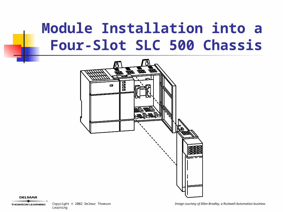
Module Installation into a Four-Slot SLC 500 Chassis
Image courtesy of Allen-Bradley, a Rockwell Automation business
Copyright © 2002 Delmar Thomson Learning
Module Installation into a Four-Slot SLC 500 Chassis
(cont’d.)
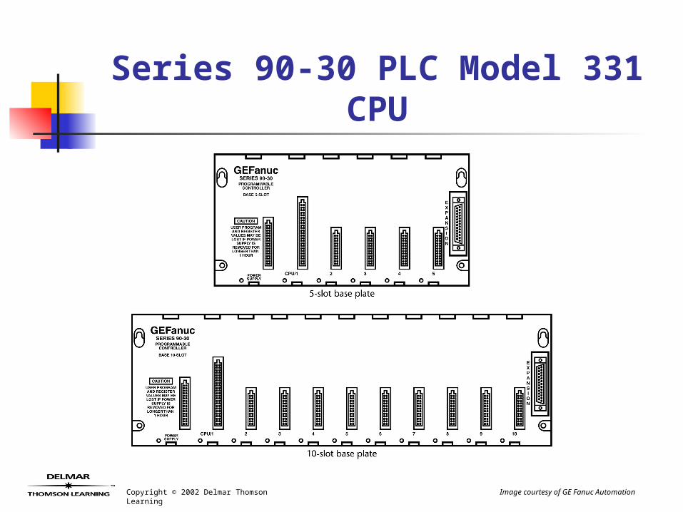
The General Electric Series 90-30 incorporates the processor into the baseplate for the low end modular PLCs.
Baseplates come in five-slot and ten-slot models.
Copyright © 2002 Delmar Thomson Learning
Series 90-30 PLC Model 331 CPU
Image courtesy of GE Fanuc Automation
Copyright © 2002 Delmar Thomson Learning
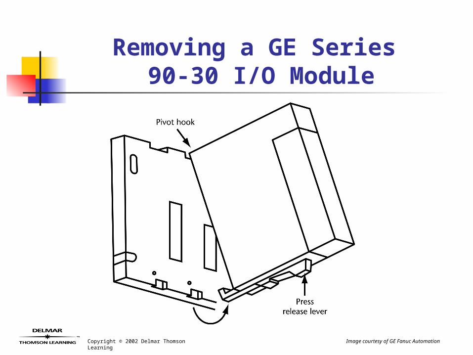
Removing a GE Series 90-30 I/O Module
Image courtesy of GE Fanuc Automation
Copyright © 2002 Delmar Thomson Learning
Local I/O ExpansionWhen more I/O is required than a
single chassis can hold, additional chassis can be added.
Communications cable connects expansion chassis together.
No processor in expansion chassis.Power supply required in all chassis.Expansion cable distance limited.
Copyright © 2002 Delmar Thomson Learning
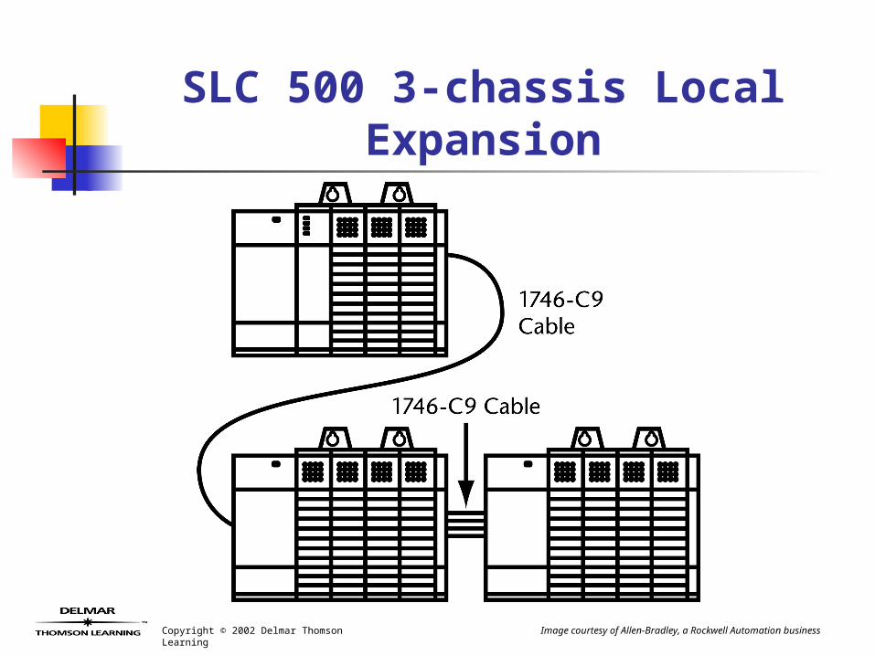
SLC 500 3-chassis Local Expansion
Image courtesy of Allen-Bradley, a Rockwell Automation business
Copyright © 2002 Delmar Thomson Learning
Remote I/O
Remote I/O allows greater cable distance between chassis.
Typically a serial link.SLC 500 remote I/O maximum
cable length 10,000 feet.Baud rate of 57.6 K bits per
second.
Copyright © 2002 Delmar Thomson Learning
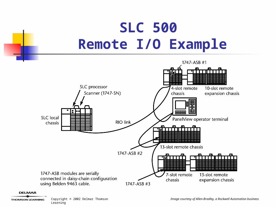
SLC 500 Remote I/O Example
Image courtesy of Allen-Bradley, a Rockwell Automation business
Copyright © 2002 Delmar Thomson Learning
SLC 500 Remote I/O Example (cont.’d)
SLC 500 uses 1747-SN scanner in local chassis.
SN scanner communicates with remote chassis.
1747-ASB communication module required in each remote chassis.
Copyright © 2002 Delmar Thomson Learning
SLC 500 Remote I/O Example (cont.’d)
Remote I/O allows I/O to be “distributed” around the plant floor.
PanelView operator interface terminals as well as variable frequency drives can be connected on a remote I/O link.
Copyright © 2002 Delmar Thomson Learning
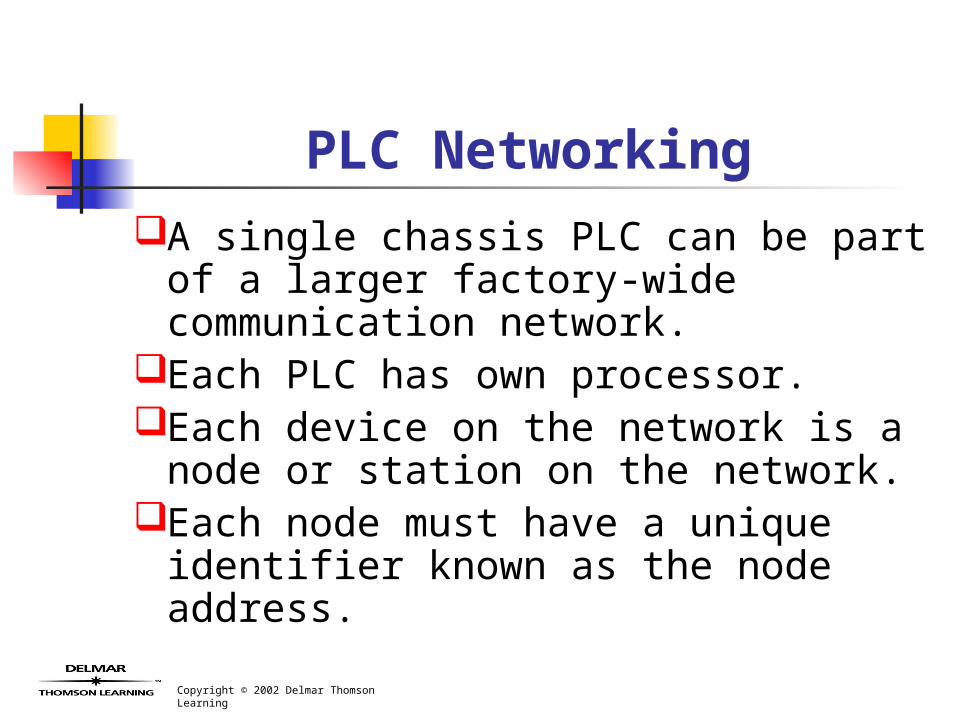
PLC NetworkingA single chassis PLC can be part of a
larger factory-wide communication network.
Each PLC has own processor.Each device on the network is a
node or station on the network.Each node must have a unique
identifier known as the node address.
Copyright © 2002 Delmar Thomson Learning
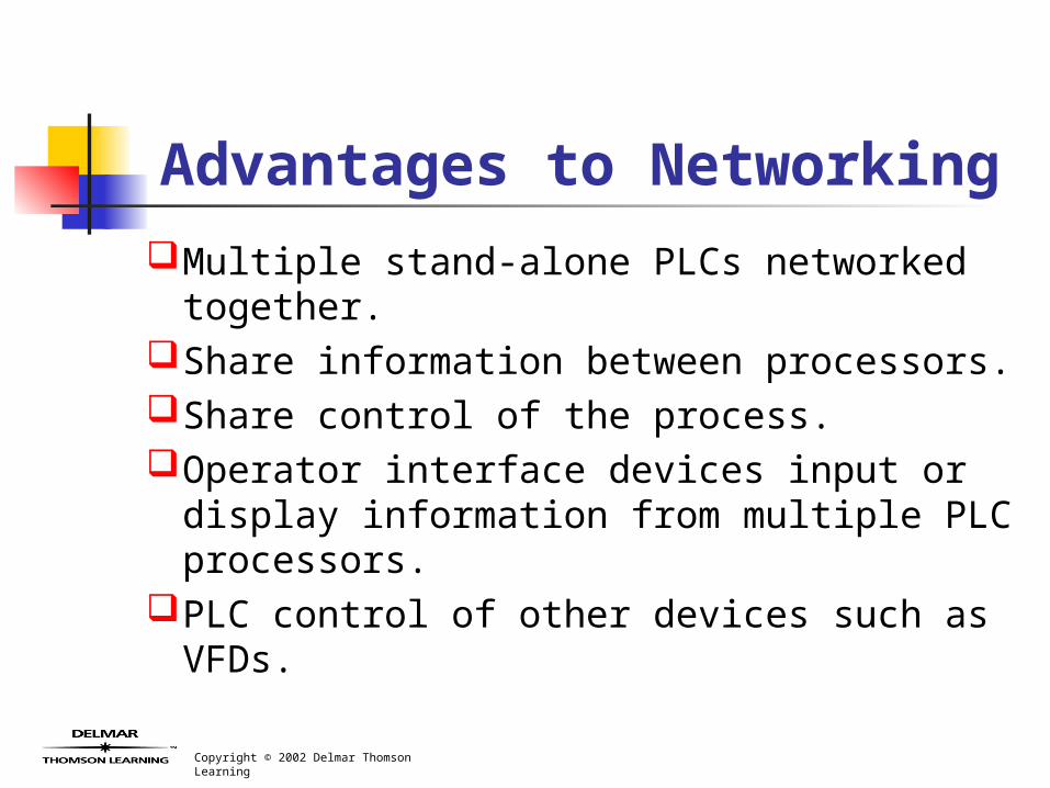
Advantages to Networking
Multiple stand-alone PLCs networked together.
Share information between processors.Share control of the process.Operator interface devices input or
display information from multiple PLC processors.
PLC control of other devices such as VFDs.
Copyright © 2002 Delmar Thomson Learning
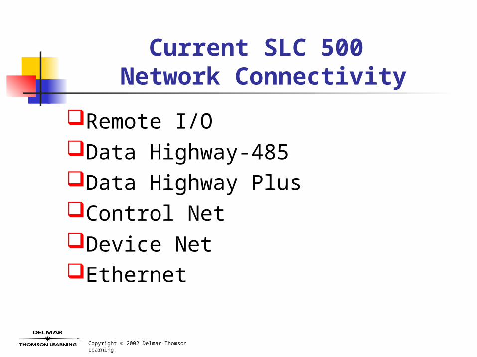
Current SLC 500 Network Connectivity
Remote I/OData Highway-485Data Highway PlusControl NetDevice NetEthernet
Copyright © 2002 Delmar Thomson Learning
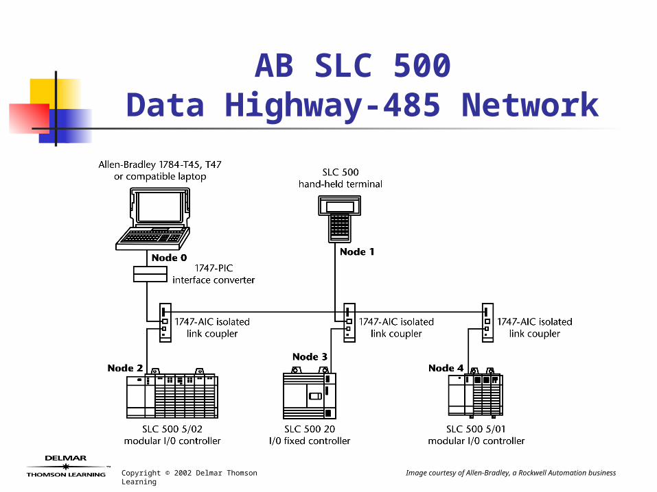
AB SLC 500 Data Highway-485 Network
Image courtesy of Allen-Bradley, a Rockwell Automation business
Copyright © 2002 Delmar Thomson Learning
Selection and Placement of I/O Modules
Consider Input and Output SignalsModules are divided into family
groups.The appropriate input or output
module is selected by determining incoming and outgoing signals.
Match I/O signals to proper module.
Copyright © 2002 Delmar Thomson Learning
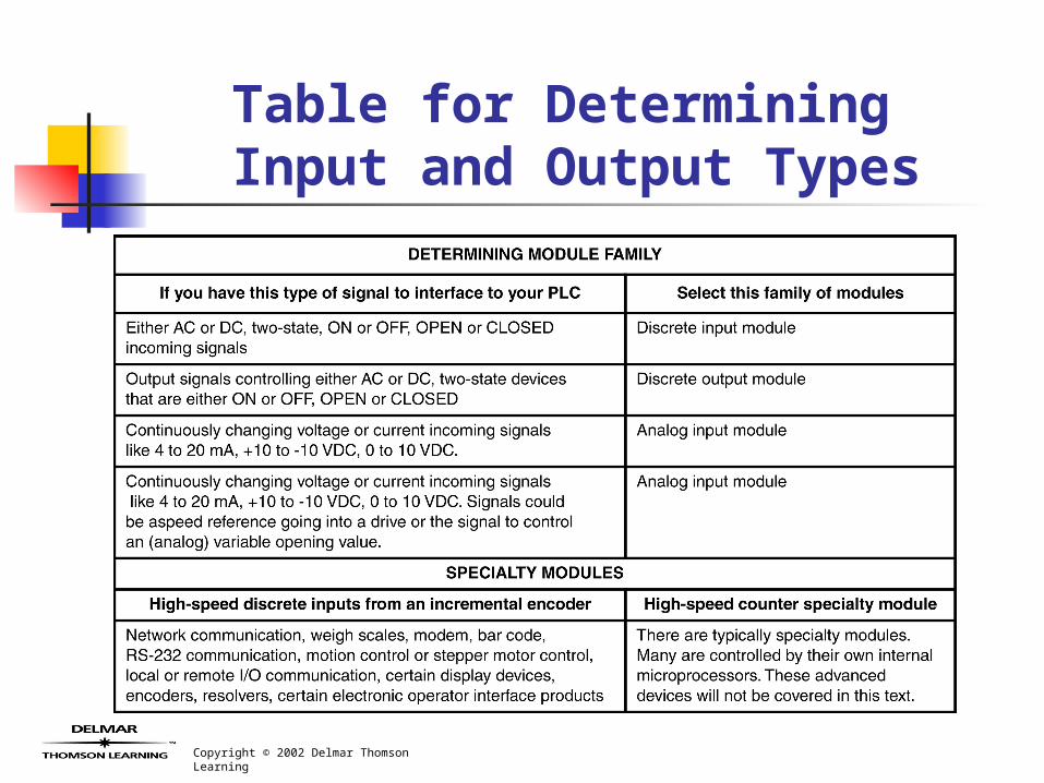
Table for Determining Input and Output Types
Copyright © 2002 Delmar Thomson Learning
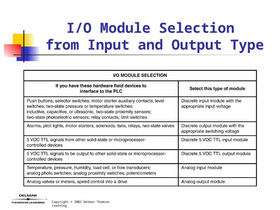
I/O Module Selection from Input and Output Type
Copyright © 2002 Delmar Thomson Learning
Power Supply Selection
Each modular PLC chassis, rack, or baseplate must have own power supply.
Power supply designed to handle specific load.
Power supply loading is dependant on modules installed.
Copyright © 2002 Delmar Thomson Learning
Power Supply Selection (cont’d.)
Proper power supply sizing will help avoid intermittent problems or power supply shutdown due to an overloaded power supply.
Copyright © 2002 Delmar Thomson Learning
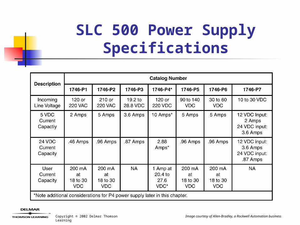
SLC 500 Power Supply Specifications
Image courtesy of Allen-Bradley, a Rockwell Automation business
Copyright © 2002 Delmar Thomson Learning
Determine Power Supply Loading
Proper size power supply is selected to handle load placed upon it by the I/O module mix.
Power supply loading can be manually calculated using manufacturers’ tables and module loading data.
PLC programming software can provide power supply loading calculation feature.
Copyright © 2002 Delmar Thomson Learning
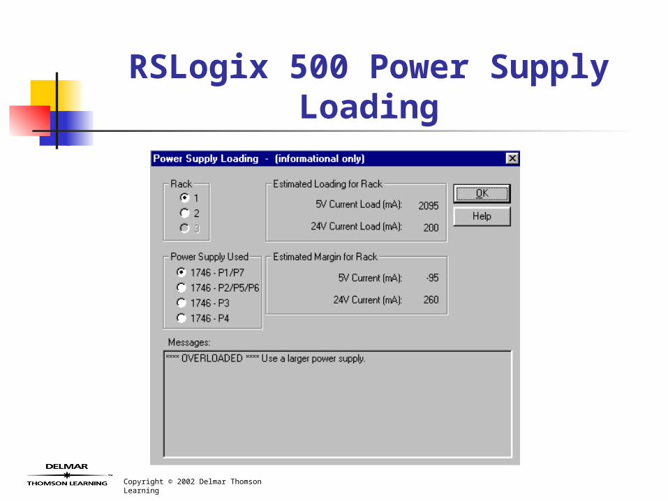
RSLogix 500 Power Supply Loading
Copyright © 2002 Delmar Thomson Learning
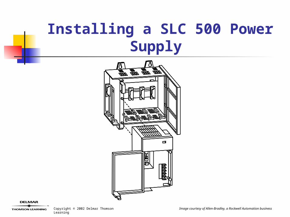
Installing a SLC 500 Power Supply
Image courtesy of Allen-Bradley, a Rockwell Automation business
Copyright © 2002 Delmar Thomson Learning
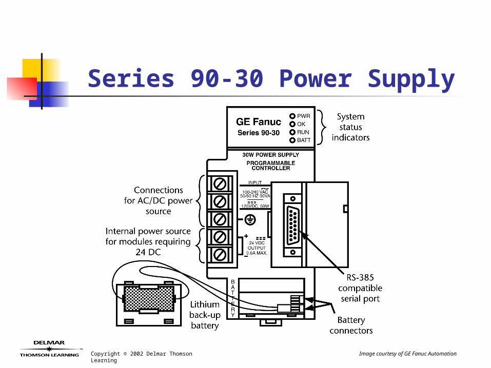
Series 90-30 Power Supply
Image courtesy of GE Fanuc Automation