Embed Size (px)
Citation preview
DatasheetSeptember 2019
Daniel™ 3415 and 3416Dual-Configuration Gas Ultrasonic Flow Meters

www.Emerson.com 1
DatasheetGas Ultrasonic Flow Meter
Advanced Check MeteringThe new dual-configuration Daniel 3415 and 3416 Gas Ultrasonic Flow Meters deliver exceptional custody transfer accuracy and reliability by combining the power and performance of a field-proven Daniel four-path chordal, British Gas-design meter with a second reflective check meter in one body. These self-verification meters provide advanced detection and validation of process disturbances to help operators identify critical issues before measurement is adversely affected.
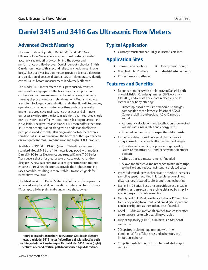
The Model 3415 meter offers a four-path custody transfer meter with a single-path reflective check meter, providing continuous real-time measurement verification and an early warning of process and/or meter deviations. With immediate alerts for blockages, contamination and other flow disturbances, operators can reduce maintenance time and costs as well as implement predictive maintenance practices and eliminate unnecessary trips into the field. In addition, the integrated check meter ensures cost-effective, continuous backup measurement is available. The ultra-reliable Model 3416 meter offers the same 3415 meter configuration along with an additional reflective path positioned vertically. This diagnostic path detects even a thin layer of liquid or buildup on the bottom of the pipe that can cause significant measurement error and higher LAUF product.
Available in DN100 to DN600 (4-in to 24-in) line sizes, each standard Model 3415 or 3416 meter is equipped with modular Daniel 3410 Series Electronics and rugged Daniel T-20 Series Transducers that offer greater tolerance to wet, rich and/or dirty gas. A new patented transducer synchronization method ensures 3410 Series Electronics provide the highest sampling rates possible, resulting in more stable ultrasonic signals for better flow resolution.
The latest version of Daniel MeterLink Software gives operators advanced insight and allows real-time meter monitoring from a PC or laptop to help eliminate unplanned shutdowns.
Figure 1: In addition to the 4-path, British Gas-design custody meter, the Model 3415 meter (left) offers a single reflective path
for integrated check metering while the Model 3416 meter (right) features a second, vertical path for advanced liquid detection.
Typical Application � Custody transfer for natural gas transmission lines
Application Sites � Transmission pipelines
� Gas plant inlets/outlets
� Production and gathering
Features and Benefits � Redundant models with a field-proven Daniel 4-path
chordal, British Gas-design meter (OIML Accuracy Class 0.5) and a 1-path or 2-path reflective check meter in one body offering:
▪ Direct inputs for pressure, temperature and gas composition that allow calculations of AGA 8 Compressibility and optional AGA 10 speed of sound
▪ Automatic calculations and totalization of corrected volume rates, mass rates and energy rates
▪ Ethernet connectivity for expedited data transfer
� Immediate detection of process disturbances via integration of chordal and reflective methodologies
▪ Provides early warning of process or gas quality issues to minimize LAUF and/or prevent equipment damage
▪ Offers a backup measurement, if needed
▪ Allows for predictive maintenance to minimize trips to the field and reduce maintenance related costs
� Patented transducer synchronization method increases sampling speed, resulting in faster detection of flow disturbances to expedite alerts and troubleshooting
� Daniel 3410 Series Electronics provide an expandable platform and an expansive archive data log to simplify accounting and dispute resolution
� New Type 4 CPU Module offers additional I/O with five frequency or digital outputs and one digital input that can be configured as the sixth output if needed
� Local LCD displays (optional) on each transmitter offer up to ten user-selectable scrolling variables
� High rangeability (>100:1) eliminates an additional meter run
� 5D upstream piping requirement (with flow conditioner) for offshore rigs and other sites with limited straight run
� Simplifies installation with no intermediate flanges required
Daniel 3415 and 3416 Gas Ultrasonic Flow Meters
� Underground storage
� Industrial interconnects
www.Emerson.com 2
September 2019Daniel 3415 and 3416
Meter Specifications:Four-Path Custody Transfer Meter
Characteristics � 4-path (eight transducers) chordal design
Meter Performance � Flow calibrated accuracy is ±0.1% of reading over entire
flow calibration range
� Repeatability is ±0.05% of reading for 1.5 to 30.5 m/s (5 to 100 ft/s)
Velocity Range � Nominal 0 to 30 m/s (0 to 100 ft/s) with over-range
performance exceeding 38 m/s (125 ft/s) on some sizes
� Meter meets or exceeds AGA 9 2017 Edition / ISO 17089 performance specifications
(1) T-21 and T-41 transducers are the only transducers available for the check meter.
(2) Refer to page 9 for additional information pertaining to operation limits.
(3) It is the equipment user’s responsibility to select the materials suitable for the intended services.
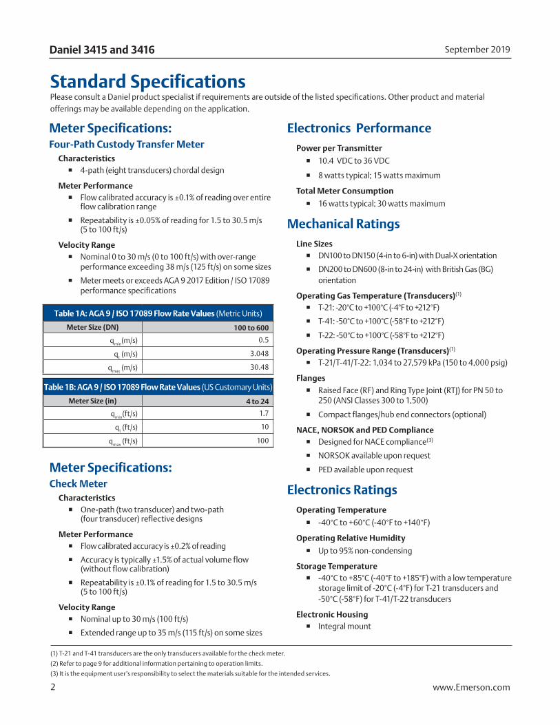
Standard SpecificationsPlease consult a Daniel product specialist if requirements are outside of the listed specifications. Other product and material offerings may be available depending on the application.
Electronics PerformancePower per Transmitter
� 10.4 VDC to 36 VDC
� 8 watts typical; 15 watts maximum
Total Meter Consumption
� 16 watts typical; 30 watts maximum
Mechanical Ratings Line Sizes
� DN100 to DN150 (4-in to 6-in) with Dual-X orientation
� DN200 to DN600 (8-in to 24-in) with British Gas (BG) orientation
Operating Gas Temperature (Transducers)(1)
� T-21: -20°C to +100°C (-4°F to +212°F)
� T-41: -50°C to +100°C (-58°F to +212°F)
� T-22: -50°C to +100°C (-58°F to +212°F)
Operating Pressure Range (Transducers)(1) � T-21/T-41/T-22: 1,034 to 27,579 kPa (150 to 4,000 psig)
Flanges
� Raised Face (RF) and Ring Type Joint (RTJ) for PN 50 to 250 (ANSI Classes 300 to 1,500)
� Compact flanges/hub end connectors (optional)
NACE, NORSOK and PED Compliance � Designed for NACE compliance(3)
� NORSOK available upon request
� PED available upon request
Electronics Ratings Operating Temperature
� -40°C to +60°C (-40°F to +140°F)
Operating Relative Humidity
� Up to 95% non-condensing
Storage Temperature � -40°C to +85°C (-40°F to +185°F) with a low temperature
storage limit of -20°C (-4°F) for T-21 transducers and -50°C (-58°F) for T-41/T-22 transducers
Electronic Housing � Integral mount
Meter Specifications:Check Meter
Characteristics � One-path (two transducer) and two-path
(four transducer) reflective designs
Meter Performance � Flow calibrated accuracy is ±0.2% of reading
� Accuracy is typically ±1.5% of actual volume flow (without flow calibration)
� Repeatability is ±0.1% of reading for 1.5 to 30.5 m/s (5 to 100 ft/s)
Velocity Range � Nominal up to 30 m/s (100 ft/s)
� Extended range up to 35 m/s (115 ft/s) on some sizes
Table 1A: AGA 9 / ISO 17089 Flow Rate Values (Metric Units)
Meter Size (DN) 100 to 600
qmin
(m/s) 0.5
qt (m/s) 3.048
qmax
(m/s) 30.48
Table 1B: AGA 9 / ISO 17089 Flow Rate Values (US Customary Units)
Meter Size (in) 4 to 24
qmin
(ft/s) 1.7
qt (ft/s) 10
qmax
(ft/s) 100
www.Emerson.com 3
DatasheetGas Ultrasonic Flow Meter
(1) Impact tested per specified ASTM standard.
(2) A995 4A material is not yet approved in Canada.
(3) Pressure rating information is for -29°C to +38°C (-20°F to +100°F). Other temperatures may reduce the maximum pressure rating of the materials.
Materials of ConstructionThe materials of construction are dependent upon application requirements that must be specified by the customer. If needed, a Daniel product specialist can provide material guidance.
Material Specifications
Body and FlangeForgings
� ASTM A350 Gr LF2 Carbon Steel(1) -46°C to +150°C (-50°F to +302°F)
� ASTM A350 Gr LF2 Carbon Steel(1) -50°C to +150°C (-58°F to +302°F)
� ASTM A182 Gr F316/F316L Stainless Steel (Dual Certified) -46°C to +150°C (-50°F to +302°F)
� ASTM A182 Gr F51 Duplex Stainless Steel(2) -50°C to +150°C (-58°F to +302°F)
� ASTM A105 Carbon Steel -29°C to +150°C (-20°F to +302°F)
Enclosure Housing � Standard: ASTM B26 Gr A356.0 T6 Aluminum
� Optional: ASTM A351 Gr CF8M Stainless Steel
Electronics Bracket Stainless Steel Material
� 316SS
Transducer Components Transducer Mounts and Holders O-rings
� Standard: Nitrile Butadiene Rubber (NBR)
� Other materials available
Transducer Mounts and Holders � ASTM A564 Type 630 Stainless Steel Mounts
� ASTM A479 316L Stainless Steel Holders
� INCONEL® ASTM B446 (UNS N06625) Gr 1 Mount (optional)
� INCONEL ASTM B446 (UNS N06625) Gr 1 Holder (optional)
Paint Specifications
Body and Flange ExteriorCarbon Steel Body Material
� 2 coat paint; inorganic zinc primer and acrylic lacquer topcoat (standard)
Stainless Steel or Duplex Body Material
� Paint (optional)
Transducer Shroud Aluminum Material
� Powder coated
Enclosure HousingAluminum Material
� 100% conversion coated and exterior coated with a polyurethane enamel
Stainless Steel Material
� Passivated (optional)
Table 2A: Body and Flange Maximum Pressure Ratings by Construction Materials [bar Meter Sizes DN100 to DN600](3)
PN Forged Carbon Steel Forged 316/316L SS Duplex SS
50 51.1 49.6 51.7
100 102.1 99.3 103.4
150 153.2 148.9 155.1
200 255.3 248.2 258.6
Table 2B: Body and Flange Maximum Pressure Ratings by Construction Materials
[psi Meter Sizes 4-in to 24-in](3)
ANSI Class(4) Forged Carbon Steel Forged 316/ 316L SS Duplex SS
300 740 720 750
600 1,480 1,440 1,500
900 2,220 2,160 2,250
1,500 3,705 3,600 3,750
www.Emerson.com 4
September 2019Daniel 3415 and 3416
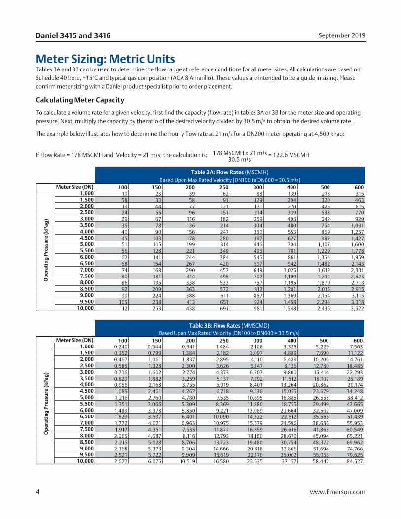
Meter Sizing: Metric UnitsTables 3A and 3B can be used to determine the flow range at reference conditions for all meter sizes. All calculations are based on Schedule 40 bore, +15°C and typical gas composition (AGA 8 Amarillo). These values are intended to be a guide in sizing. Please confirm meter sizing with a Daniel product specialist prior to order placement.
Calculating Meter Capacity
To calculate a volume rate for a given velocity, first find the capacity (flow rate) in tables 3A or 3B for the meter size and operating pressure. Next, multiply the capacity by the ratio of the desired velocity divided by 30.5 m/s to obtain the desired volume rate.
The example below illustrates how to determine the hourly flow rate at 21 m/s for a DN200 meter operating at 4,500 kPag:
If Flow Rate = 178 MSCMH and Velocity = 21 m/s, the calculation is: 178 MSCMH x 21 m/s = 122.6 MSCMH 30.5 m/s
Table 3A: Flow Rates (MSCMH) Based Upon Max Rated Velocity [DN100 to DN600 = 30.5 m/s]
Meter Size (DN) 100 150 200 250 300 400 500 600
Op
erat
ing
Pre
ssu
re (k
Pag
)
1,000 10 23 39 62 88 139 218 3151,500 58 33 58 91 129 204 320 4632,000 19 44 77 121 171 270 425 6152,500 24 55 96 151 214 339 533 7703,000 29 67 116 182 259 408 642 9293,500 35 78 136 214 304 480 754 1,0914,000 40 90 156 247 350 553 869 1,2574,500 45 103 178 280 397 627 987 1,4275,000 51 115 199 314 446 704 1,107 1,6005,500 56 128 221 349 495 781 1,229 1,7786,000 62 141 244 384 545 861 1,354 1,9596,500 68 154 267 420 597 942 1,482 2,1437,000 74 168 290 457 649 1,025 1,612 2,3317,500 80 181 314 495 702 1,109 1,744 2,5238,000 86 195 338 533 757 1,195 1,879 2,7188,500 92 209 363 572 812 1,281 2,015 2,9159,000 99 224 388 611 867 1,369 2,154 3,1159,500 105 238 413 651 924 1,458 2,294 3,318
10,000 112 253 438 691 981 1,548 2,435 3,522
Table 3B: Flow Rates (MMSCMD) Based Upon Max Rated Velocity [DN100 to DN600 = 30.5 m/s]
Meter Size (DN) 100 150 200 250 300 400 500 600
Op
erat
ing
Pre
ssu
re (k
Pag
)
1,000 0.240 0.544 0.941 1.484 2.106 3.325 5.229 7.5631,500 0.352 0.799 1.384 2.182 3.097 4.889 7.690 11.1222,000 0.467 1.061 1.837 2.895 4.110 6.489 10.206 14.7612,500 0.585 1.328 2.300 3.626 5.147 8.126 12.780 18.4853,000 0.706 1.602 2.774 4.373 6.207 9.800 15.414 22.2933,500 0.829 1.882 3.259 5.137 7.292 11.512 18.107 26.1894,000 0.956 2.168 3.755 5.919 8.401 13.264 20.862 30.1744,500 1.085 2.461 4.262 6.718 9.536 15.055 23.679 34.2485,000 1.216 2.760 4.780 7.535 10.695 16.885 26.558 38.4125,500 1.351 3.066 5.309 8.369 11.880 18.755 29.499 42.6656,000 1.489 3.378 5.850 9.221 13.089 20.664 32.502 47.0096,500 1.629 3.697 6.401 10.090 14.322 22.612 35.565 51.4397,000 1.772 4.021 6.963 10.975 15.579 24.596 38.686 55.9537,500 1.917 4.351 7.535 11.877 16.859 26.616 41.863 60.5498,000 2.065 4.687 8.116 12.793 18.160 28.670 45.094 65.2218,500 2.215 5.028 8.706 13.723 19.480 30.754 48.372 69.9629,000 2.368 5.373 9.304 14.666 20.818 32.866 51.694 74.7669,500 2.521 5.722 9.909 15.619 22.170 35.002 55.053 79.625
10,000 2.677 6.075 10.519 16.580 23.535 37.157 58.442 84.527
www.Emerson.com 5
DatasheetGas Ultrasonic Flow Meter
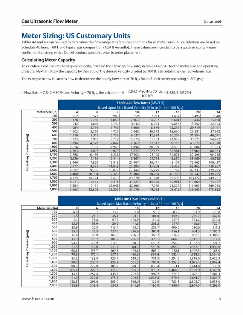
Meter Sizing: US Customary UnitsTables 4A and 4B can be used to determine the flow range at reference conditions for all meter sizes. All calculations are based on Schedule 40 bore, +60°F and typical gas composition (AGA 8 Amarillo). These values are intended to be a guide in sizing. Please confirm meter sizing with a Daniel product specialist prior to order placement.
Calculating Meter CapacityTo calculate a volume rate for a given velocity, first find the capacity (flow rate) in tables 4A or 4B for the meter size and operating pressure. Next, multiply the capacity by the ratio of the desired velocity divided by 100 ft/s to obtain the desired volume rate.
The example below illustrates how to determine the hourly flow rate at 70 ft/s for an 8-inch meter operating at 800 psig:
If Flow Rate = 7,842 MSCFH and Velocity = 70 ft/s, the calculation is: 7,842 MSCFH x 70 ft/s = 5,489.4 MSCFH 100 ft/s
Table 4A: Flow Rates (MSCFH) Based Upon Max Rated Velocity [4-in to 24-in = 100 ft/s]
Meter Size (in) 4 6 8 10 12 16 20 24
Op
erat
ing
Pre
ssu
re (p
sig
)
100 252 571 989 1,559 2,213 3,494 5,495 7,948200 478 1,086 1,880 2,963 4,207 6,641 10,446 15,108300 712 1,616 2,799 4,412 6,263 9,888 15,552 22,493400 954 2,164 3,747 5,906 8,384 13,236 20,819 30,111500 1,202 2,729 4,725 7,448 10,572 16,690 26,251 37,968600 1,459 3,311 5,733 9,037 12,828 20,252 31,854 46,071700 1,723 3,911 6,772 10,675 15,153 23,923 37,627 54,422800 1,996 4,529 7,842 12,362 17,547 27,703 43,572 63,020900 2,276 5,165 8,943 14,096 20,009 31,590 49,686 71,863
1,000 2,563 5,817 10,073 15,877 22,537 35,581 55,964 80,9431,100 2,858 6,486 11,231 17,702 25,128 39,671 62,396 90,2461,200 3,159 7,169 12,414 19,567 27,774 43,850 68,969 99,7521,300 3,466 7,865 13,619 21,467 30,471 48,107 75,665 109,4371,400 3,777 8,571 14,842 23,395 33,208 52,428 82,462 119,2671,500 4,092 9,285 16,079 25,344 35,975 56,797 89,333 129,2051,600 4,408 10,004 17,323 27,306 38,760 61,193 96,247 139,2051,700 4,725 10,724 18,570 29,270 41,548 65,595 103,172 149,2211,800 5,041 11,441 19,811 31,227 44,326 69,981 110,069 159,1971,900 5,354 12,151 21,041 33,166 47,079 74,327 116,905 169,0832,000 5,663 12,852 22,255 35,079 49,793 78,612 123,645 178,832
Table 4B: Flow Rates (MMSCFD) Based Upon Max Rated Velocity [4-in to 24-in = 100 ft/s]
Meter Size (in) 4 6 8 10 12 16 20 24
Op
erat
ing
Pre
ssu
re (p
sig
)
100 6.0 13.7 23.7 37.4 53.1 83.9 131.9 190.8200 11.5 26.1 45.1 71.1 101.0 159.4 250.7 362.6300 17.1 38.8 67.2 105.9 150.3 237.3 373.2 539.8400 22.9 51.9 89.9 141.8 201.2 317.7 499.6 722.7500 28.9 65.5 113.4 178.7 253.7 400.6 630.0 911.2600 35.0 79.5 137.6 216.9 307.9 486.1 764.5 1,105.7700 41.4 93.9 162.5 256.2 363.7 574.2 903.1 1,306.1800 47.9 108.7 188.2 296.7 421.1 664.9 1,045.7 1,512.5900 54.6 123.9 214.6 338.3 480.2 758.2 1,192.5 1,724.7
1,000 61.5 139.6 241.7 381.1 540.9 854.0 1,343.1 1,942.61,100 68.6 155.7 269.5 424.8 603.1 952.1 1,497.5 2,165.91,200 75.8 172.1 297.9 469.6 666.6 1,052.4 1,655.3 2,394.01,300 83.2 188.8 326.9 515.2 731.3 1,154.6 1,816.0 2,626.51,400 90.6 205.7 356.2 561.5 797.0 1,258.3 1,979.1 2,862.41,500 98.2 222.9 385.9 608.3 863.4 1,363.1 2,144.0 3,100.91,600 105.8 240.1 415.8 655.3 930.2 1,468.6 2,309.9 3,340.91,700 113.4 257.4 445.7 702.5 997.2 1,574.3 2,476.1 3,581.31,800 121.0 274.6 475.5 749.5 1,063.8 1,679.5 2,641.7 3,820.71,900 128.5 291.6 505.0 796.0 1,129.9 1,783.8 2,805.7 4,058.02,000 135.9 308.4 534.1 841.9 1,195.0 1,886.7 2,967.5 4,292.0
(1) The analog-to-digital conversion accuracy is within ±0.05% of full scale over the operating temperature range.(2) A 24 volt DC power supply is available to provide power to the sensors.(3) AI-1 and AI-2 are electronically isolated and operate in sink mode. The input contains a series resistance for HART® Communicators to be connected for sensor configuration.(4) The analog output zero scale offset error is within ±0.1% of full scale and gain error is within ±0.2% of full scale. The total output drift is within ±50 ppm of full scale per °C.
Table 6: CPU Module I/O Connections (maximum wire gauge is 18 AWG)
I/O Connection Type Qty Description
Serial Communications Serial RS232/RS485 Port
1 ▪ Modbus RTU/ASCII
▪ 115 kbps baud rate
Ethernet Port (TCP/IP) 100BaseT 1 ▪ Modbus TCP
Digital Input(1) Contact Closure 1 ▪ Status
▪ Single polarity
Analog Inputs(2) 4-20 mA 2 ▪ AI-1 Temperature(3)
▪ AI-2 Pressure (3)
Frequency/Digital Outputs TTL/Open Collector 5 ▪ User Configurable (can configure Digital Input as 6th Frequency/Digital Output)
Table 7: Optional I/O Expansion Module
I/O Connection Type Qty Description
Serial Communications Serial RS232/RS485 Port
1 ▪ Modbus RTU/ASCII
▪ 15 kbps baud rate
▪ RS232/RS485 Half Duplex
Ethernet Port 1 ▪ 100BaseT
▪ Three Ports
Analog Output 4-20 mA 1 ▪ Reserved for future use
Input/Output
▪ RS232/RS485 Full Duplex
▪ RS485 Half Duplex
Optional I/O Expansion Slot(s) by Enclosure Type: Standard Enclosure: 1 RS232/RS485 Half Duplex, 2-Wire OR 1 I/O Expansion Module Extended (Retrofit) Enclosure: 2 RS232/RS485 Half Duplex, 2-Wire OR 1 I/O Expansion Module and 1 RS232/RS485 Half Duplex, 2-Wire
September 2019Daniel 3415 and 3416
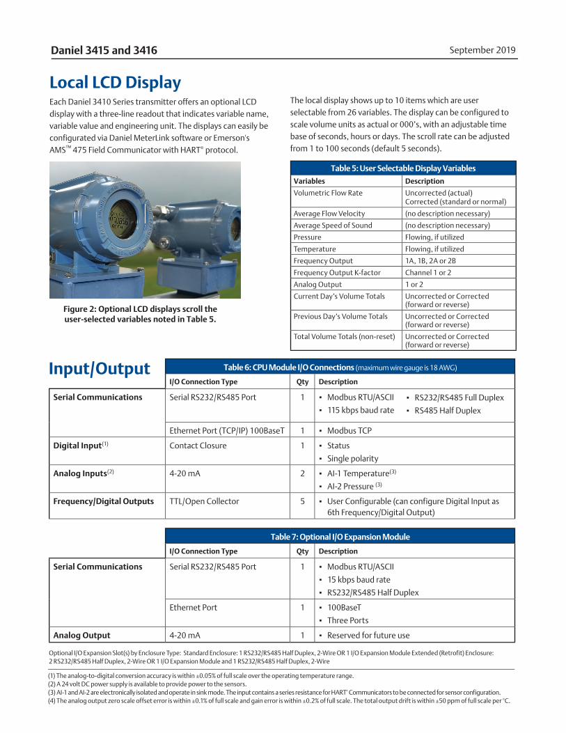
Local LCD DisplayEach Daniel 3410 Series transmitter offers an optional LCD display with a three-line readout that indicates variable name, variable value and engineering unit. The displays can easily be configurated via Daniel MeterLink software or Emerson's AMS™ 475 Field Communicator with HART® protocol.
The local display shows up to 10 items which are user selectable from 26 variables. The display can be configured to scale volume units as actual or 000’s, with an adjustable time base of seconds, hours or days. The scroll rate can be adjusted from 1 to 100 seconds (default 5 seconds).
Table 5: User Selectable Display Variables
Variables Description
Volumetric Flow Rate Uncorrected (actual) Corrected (standard or normal)
Average Flow Velocity (no description necessary)
Average Speed of Sound (no description necessary)
Pressure Flowing, if utilized
Temperature Flowing, if utilized
Frequency Output 1A, 1B, 2A or 2B
Frequency Output K-factor Channel 1 or 2
Analog Output 1 or 2
Current Day’s Volume Totals Uncorrected or Corrected (forward or reverse)
Previous Day’s Volume Totals Uncorrected or Corrected (forward or reverse)
Total Volume Totals (non-reset) Uncorrected or Corrected (forward or reverse)
Figure 2: Optional LCD displays scroll the user-selected variables noted in Table 5.
www.Emerson.com 7
DatasheetGas Ultrasonic Flow Meter
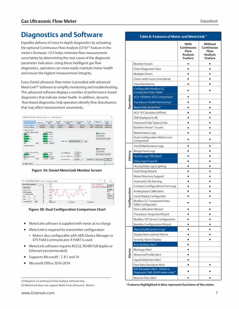
Diagnostics and SoftwareExpedite delivery of more in-depth diagnostics by activating the optional Continuous Flow Analysis (CFA)(1) feature in the meter's firmware. CFA helps minimize flow measurement uncertainty by determining the root cause of the diagnostic parameter indication. Using these intelligent gas flow diagnostics, operators can more easily maintain meter health and ensure the highest measurement integrity.
Every Daniel ultrasonic flow meter is provided with advanced MeterLink™ Software to simplify monitoring and troubleshooting. This advanced software displays a number of performance-based diagnostics that indicate meter health. In addition, dynamic flow-based diagnostics help operators identify flow disturbances that may affect measurement uncertainty.
(1) Requires a Continuous Flow Analysis software key.
(2) MeterLink does not support Mark II Gas Ultrasonic Meters.
Table 8: Features of Meter and MeterLink (2)
With Continuous
Flow Analysis Feature
Without Continuous
Flow Analysis Feature
Op
erat
ion
Monitor Screen
Chart Diagnostic Data
Multiple Charts
Charts with Green Limit Bands
View Waveforms
Configurable Modbus GC Component Data Table*
AGA 10/Meter SOS Comparison*
Transducer Health Monitoring*
Read-Only Serial Port*
AGA 10 Calculator (offline)
SNR displayed in dB
Improved Help Topics/Links
Baseline ViewerTM (4-path)
Maintenance Logs
Dual-Configuration Meters Live Comparison
His
tory
Trend Maintenance Logs
Merge Event Logs
Hourly Logs (180 days)*
Daily Logs (5 years)*
Hourly/Daily Log Graphing
Co
nfi
gu
rati
on
Field Setup Wizard
Meter Directory Support
Automatic File Naming
Compare Configurations from Logs
Analog Input Calibration
Local Display Configurator
Modbus GC Component Data Table Configurator
Flow Calibration Wizard
Transducer Swap Out Wizard
Modbus TCP Server Configuration
Baseline Configuration Wizard
Ala
rms
Alarm/Audit/System Logs*
Display New Latched Alarms
Severity Alarm Display
Bore Buildup Alert*
Blockage Alert
Abnormal Profile Alert
Liquid Detection Alert
Flow Rate Deviation AlertSOS Deviation Alert: Check vs. Diagnostic Path (3416 meter only)*
Reverse Flow Alert
* Features highlighted in blue represent functions of the meter.
� MeterLink software is supplied with meter at no charge
� MeterLink is required for transmitter configuration
▪ Meters also configurable with AMS Device Manager or 475 Field Communicator if HART is used
� MeterLink software requires RS232, RS485 full duplex or Ethernet (recommended)
� Supports Microsoft®, 7, 8.1 and 10
� Microsoft Office 2010-2019
Figure 3A: Daniel MeterLink Monitor Screen
Figure 3B: Dual Configuration Comparison Chart
www.Emerson.com 8
September 2019Daniel 3415 and 3416
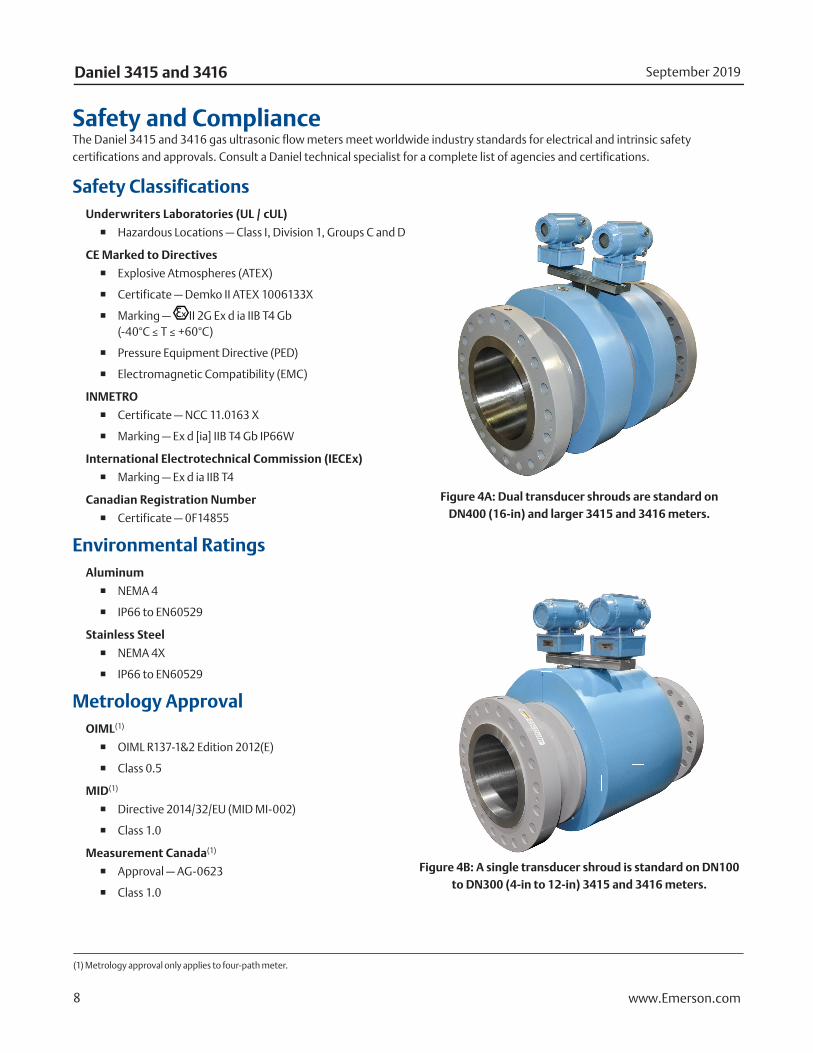
Safety and ComplianceThe Daniel 3415 and 3416 gas ultrasonic flow meters meet worldwide industry standards for electrical and intrinsic safety certifications and approvals. Consult a Daniel technical specialist for a complete list of agencies and certifications.
Safety ClassificationsUnderwriters Laboratories (UL / cUL)
� Hazardous Locations — Class I, Division 1, Groups C and D
CE Marked to Directives
� Explosive Atmospheres (ATEX)
� Certificate — Demko II ATEX 1006133X
� Marking — II 2G Ex d ia IIB T4 Gb(-40°C ≤ T ≤ +60°C)
� Pressure Equipment Directive (PED)
� Electromagnetic Compatibility (EMC)
INMETRO
� Certificate — NCC 11.0163 X
� Marking — Ex d [ia] IIB T4 Gb IP66W
International Electrotechnical Commission (IECEx)
� Marking — Ex d ia IIB T4
Canadian Registration Number
� Certificate — 0F14855
Environmental RatingsAluminum
� NEMA 4
� IP66 to EN60529
Stainless Steel
� NEMA 4X
� IP66 to EN60529
Metrology ApprovalOIML(1)
� OIML R137-1&2 Edition 2012(E)
� Class 0.5
MID(1)
� Directive 2014/32/EU (MID MI-002)
� Class 1.0
Measurement Canada(1)
� Approval — AG-0623
� Class 1.0
(1) Metrology approval only applies to four-path meter.
Figure 4A: Dual transducer shrouds are standard on DN400 (16-in) and larger 3415 and 3416 meters.
Figure 4B: A single transducer shroud is standard on DN100 to DN300 (4-in to 12-in) 3415 and 3416 meters.
www.Emerson.com 9
DatasheetGas Ultrasonic Flow Meter
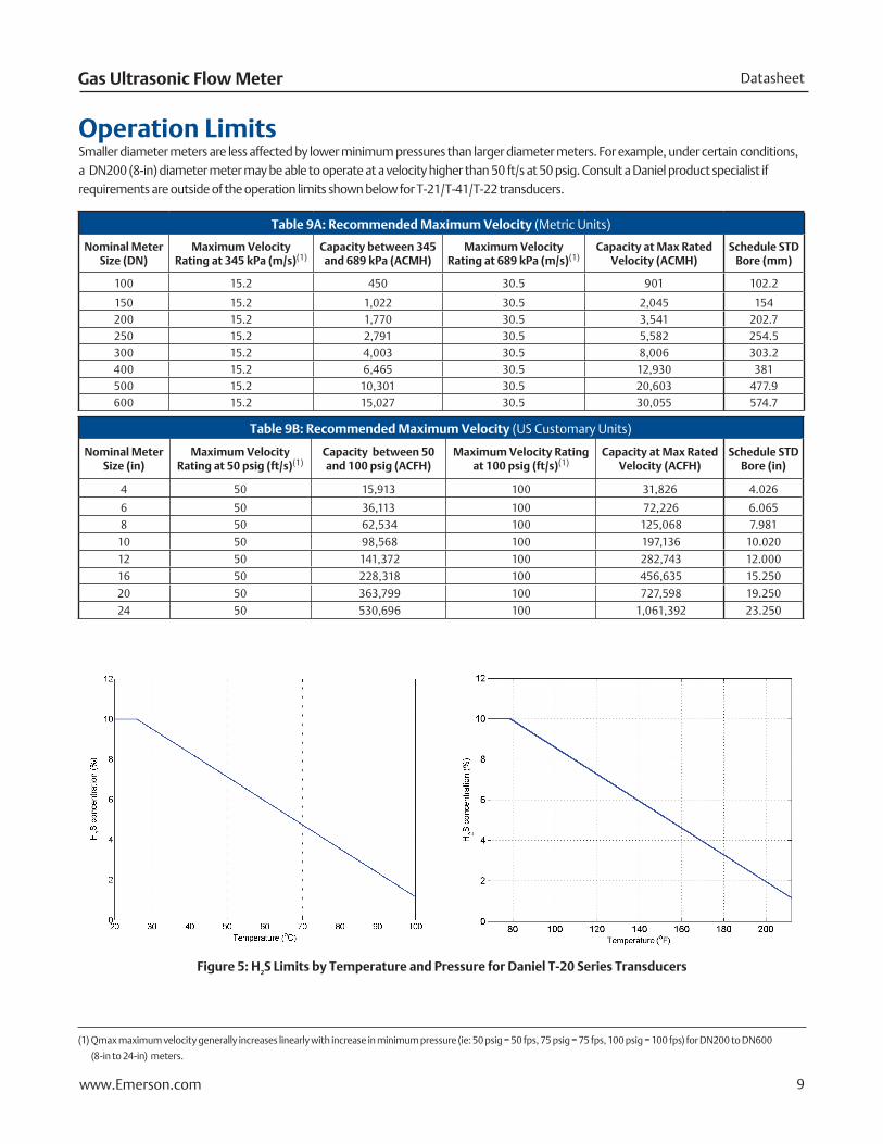
(1) Qmax maximum velocity generally increases linearly with increase in minimum pressure (ie: 50 psig = 50 fps, 75 psig = 75 fps, 100 psig = 100 fps) for DN200 to DN600
(8-in to 24-in) meters.
Operation LimitsSmaller diameter meters are less affected by lower minimum pressures than larger diameter meters. For example, under certain conditions, a DN200 (8-in) diameter meter may be able to operate at a velocity higher than 50 ft/s at 50 psig. Consult a Daniel product specialist if requirements are outside of the operation limits shown below for T-21/T-41/T-22 transducers.
Figure 5: H2S Limits by Temperature and Pressure for Daniel T-20 Series Transducers
Table 9A: Recommended Maximum Velocity (Metric Units)
Nominal Meter Size (DN)
Maximum Velocity Rating at 345 kPa (m/s)(1)
Capacity between 345 and 689 kPa (ACMH)
Maximum Velocity Rating at 689 kPa (m/s)(1)
Capacity at Max Rated Velocity (ACMH)
Schedule STD Bore (mm)
100 15.2 450 30.5 901 102.2
150 15.2 1,022 30.5 2,045 154200 15.2 1,770 30.5 3,541 202.7250 15.2 2,791 30.5 5,582 254.5300 15.2 4,003 30.5 8,006 303.2400 15.2 6,465 30.5 12,930 381500 15.2 10,301 30.5 20,603 477.9600 15.2 15,027 30.5 30,055 574.7
Table 9B: Recommended Maximum Velocity (US Customary Units)
Nominal Meter Size (in)
Maximum Velocity Rating at 50 psig (ft/s)(1)
Capacity between 50 and 100 psig (ACFH)
Maximum Velocity Rating at 100 psig (ft/s)(1)
Capacity at Max Rated Velocity (ACFH)
Schedule STD Bore (in)
4 50 15,913 100 31,826 4.026
6 50 36,113 100 72,226 6.0658 50 62,534 100 125,068 7.981
10 50 98,568 100 197,136 10.020
12 50 141,372 100 282,743 12.000
16 50 228,318 100 456,635 15.250
20 50 363,799 100 727,598 19.250
24 50 530,696 100 1,061,392 23.250
www.Emerson.com 10
September 2019Daniel 3415 and 3416
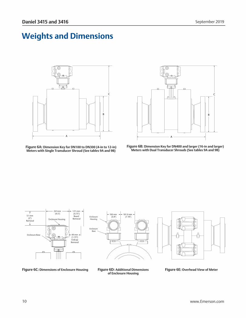
Figure 6C: Dimensions of Enclosure Housing Figure 6E: Overhead View of Meter
Figure 6A: Dimension Key for DN100 to DN300 (4-in to 12-in) Meters with Single Transducer Shroud (See tables 9A and 9B)
Figure 6B: Dimension Key for DN400 and larger (16-in and larger) Meters with Dual Transducer Shrouds (See tables 9A and 9B)
Figure 6D: Additional Dimensions of Enclosure Housing
Weights and Dimensions
C
B
A
C
B
A
51 mm (2")
Removal
241mm (9.5")
44 mm(1.75")Endcap
Removal
121 mm (4.75")Board
RemovalEnclosure Housing
Enclosure Base
150 mm (5.9")
181.9 mm (7.16")Enclosure
Housing
Enclosure Base
C
B
A
51 mm (2")
Removal
241mm (9.5")
44 mm(1.75")Endcap
Removal
121 mm (4.75")Board
RemovalEnclosure Housing
Enclosure Base
150 mm (5.9")
181.9 mm (7.16")Enclosure
Housing
Enclosure Base
C
B
A
C
B
A
51 mm (2")
Removal
241mm (9.5")
44 mm(1.75")Endcap
Removal
121 mm (4.75")Board
RemovalEnclosure Housing
Enclosure Base
150 mm (5.9")
181.9 mm (7.16")Enclosure
Housing
Enclosure Base
www.Emerson.com 11
DatasheetGas Ultrasonic Flow Meter
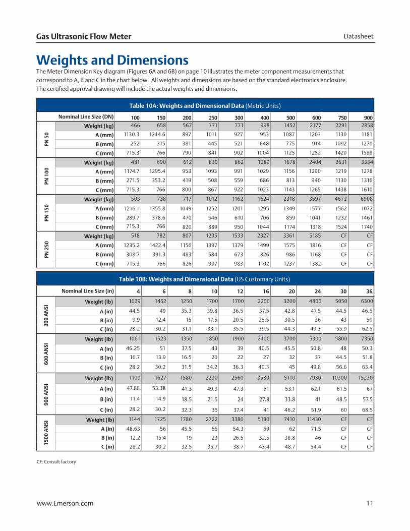
Weights and DimensionsThe Meter Dimension Key diagram (Figures 6A and 6B) on page 10 illustrates the meter component measurements that correspond to A, B and C in the chart below. All weights and dimensions are based on the standard electronics enclosure. The certified approval drawing will include the actual weights and dimensions.
Table 10A: Weights and Dimensional Data (Metric Units)
Nominal Line Size (DN) 100 150 200 250 300 400 500 600 750 900
PN 5
0
Weight (kg) 466 658 567 771 771 998 1452 2177 2291 2858
A (mm) 1130.3 1244.6 897 1011 927 953 1087 1207 1130 1181
B (mm) 252 315 381 445 521 648 775 914 1092 1270
C (mm) 715.3 766 790 841 902 1004 1125 1252 1420 1588
PN 1
00
Weight (kg) 481 690 612 839 862 1089 1678 2404 2631 3334
A (mm) 1174.7 1295.4 953 1093 991 1029 1156 1290 1219 1278
B (mm) 271.5 353.2 419 508 559 686 813 940 1130 1316
C (mm) 715.3 766 800 867 922 1023 1143 1265 1438 1610
PN 1
50
Weight (kg) 503 738 717 1012 1162 1624 2318 3597 4672 6908
A (mm) 1216.1 1355.8 1049 1252 1201 1295 1349 1577 1562 1072
B (mm) 289.7 378.6 470 546 610 706 859 1041 1232 1461
C (mm) 715.3 766 820 889 950 1044 1174 1318 1524 1740
PN 2
50
Weight (kg) 518 782 807 1235 1533 2327 3361 5185 CF CF
A (mm) 1235.2 1422.4 1156 1397 1379 1499 1575 1816 CF CF
B (mm) 308.7 391.3 483 584 673 826 986 1168 CF CF
C (mm) 715.3 766 826 907 983 1102 1237 1382 CF CF
Table 10B: Weights and Dimensional Data (US Customary Units)
Nominal Line Size (in) 4 6 8 10 12 16 20 24 30 36
300
AN
SI
Weight (lb) 1029 1452 1250 1700 1700 2200 3200 4800 5050 6300
A (in) 44.5 49 35.3 39.8 36.5 37.5 42.8 47.5 44.5 46.5
B (in) 9.9 12.4 15 17.5 20.5 25.5 30.5 36 43 50
C (in) 28.2 30.2 31.1 33.1 35.5 39.5 44.3 49.3 55.9 62.5
600
AN
SI
Weight (lb) 1061 1523 1350 1850 1900 2400 3700 5300 5800 7350
A (in) 46.25 51 37.5 43 39 40.5 45.5 50.8 48 50.3
B (in) 10.7 13.9 16.5 20 22 27 32 37 44.5 51.8
C (in) 28.2 30.2 31.5 34.2 36.3 40.3 45 49.8 56.6 63.4
900
AN
SI
Weight (lb) 1109 1627 1580 2230 2560 3580 5110 7930 10300 15230
A (in) 47.88 53.38 41.3 49.3 47.3 51 53.1 62.1 61.5 67
B (in) 11.4 14.9 18.5 21.5 24 27.8 33.8 41 48.5 57.5
C (in) 28.2 30.2 32.3 35 37.4 41 46.2 51.9 60 68.5
1500
AN
SI Weight (lb) 1144 1725 1780 2722 3380 5130 7410 11430 CF CF
A (in) 48.63 56 45.5 55 54.3 59 62 71.5 CF CF
B (in) 12.2 15.4 19 23 26.5 32.5 38.8 46 CF CF
C (in) 28.2 30.2 32.5 35.7 38.7 43.4 48.7 54.4 CF CF
CF: Consult factory
www.Emerson.com 12
September 2019Daniel 3415 and 3416
15D min
3D min(1)
2D min
3D min(1)
2D min
3D min(1)
2D min
3D min
Flow Conditioner: CPA 55E
5D 5D
3D min
3D min 3D min
10D5D min
5D min
Flow Conditioner: Daniel Profiler, CPA 50E or CPA 55E
Flow Conditioner: CPA 55E Flow Conditioner: CPA 55E
T
T
T
T
P
P
P
P
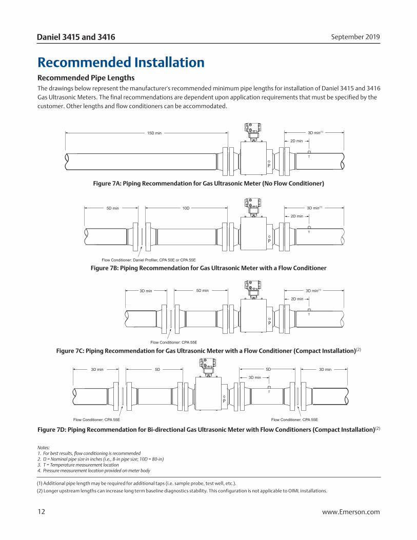
Recommended InstallationRecommended Pipe LengthsThe drawings below represent the manufacturer's recommended minimum pipe lengths for installation of Daniel 3415 and 3416 Gas Ultrasonic Meters. The final recommendations are dependent upon application requirements that must be specified by the customer. Other lengths and flow conditioners can be accommodated.
Notes: 1. For best results, flow conditioning is recommended 2. D = Nominal pipe size in inches (i.e., 8-in pipe size; 10D = 80-in) 3. T = Temperature measurement location4. Pressure measurement location provided on meter body
Figure 7B: Piping Recommendation for Gas Ultrasonic Meter with a Flow Conditioner
Figure 7A: Piping Recommendation for Gas Ultrasonic Meter (No Flow Conditioner)
Figure 7C: Piping Recommendation for Gas Ultrasonic Meter with a Flow Conditioner (Compact Installation)(2)
Figure 7D: Piping Recommendation for Bi-directional Gas Ultrasonic Meter with Flow Conditioners (Compact Installation)(2)
(1) Additional pipe length may be required for additional taps (i.e. sample probe, test well, etc.).
(2) Longer upstream lengths can increase long term baseline diagnostics stability. This configuration is not applicable to OIML installations.
www.Emerson.com 13
DatasheetGas Ultrasonic Flow Meter
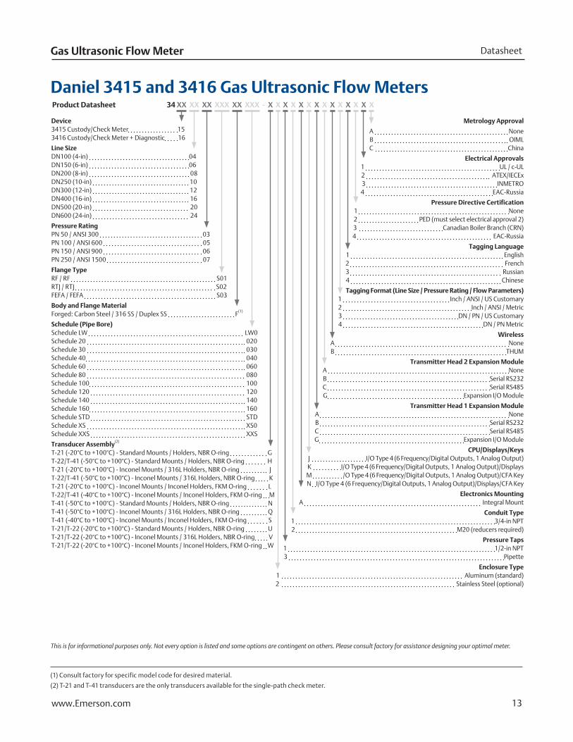
Metrology Approval
A NoneB OIMLC China
Electrical Approvals1 UL / c-UL2 ATEX/IECEx3 INMETRO4 EAC-Russia
Pressure Directive Certification1 None
2 PED (must select electrical approval 2)3 Canadian Boiler Branch (CRN)4 EAC-Russia
Tagging Language1 English2 French3 Russian4 Chinese
Tagging Format (Line Size / Pressure Rating / Flow Parameters)1 Inch / ANSI / US Customary2 Inch / ANSI / Metric3 DN / PN / US Customary4 DN / PN Metric
WirelessA NoneB THUM
Transmitter Head 2 Expansion ModuleA NoneB Serial RS232C Serial RS485G Expansion I/O Module
Transmitter Head 1 Expansion ModuleA NoneB Serial RS232C Serial RS485G Expansion I/O Module
CPU/Displays/KeysJ I/O Type 4 (6 Frequency/Digital Outputs, 1 Analog Output)K I/O Type 4 (6 Frequency/Digital Outputs, 1 Analog Output)/DisplaysM /O Type 4 (6 Frequency/Digital Outputs, 1 Analog Output)/CFA KeyN I/O Type 4 (6 Frequency/Digital Outputs, 1 Analog Output)/Displays/CFA Key
Electronics MountingA Integral Mount
Conduit Type1 3/4-in NPT2 M20 (reducers required)
Pressure Taps1 1/2-in NPT3 Pipette
Enclosure Type 1 Aluminum (standard)2 Stainless Steel (optional)
Device3415 Custody/Check Meter 153416 Custody/Check Meter + Diagnostic 16
Line SizeDN100 (4-in) 04DN150 (6-in) 06 DN200 (8-in) 08DN250 (10-in) 10DN300 (12-in) 12DN400 (16-in) 16DN500 (20-in) 20DN600 (24-in) 24
Pressure RatingPN 50 / ANSI 300 03PN 100 / ANSI 600 05PN 150 / ANSI 900 06PN 250 / ANSI 1500 07
Flange TypeRF / RF S01RTJ / RTJ S02FEFA / FEFA S03
Body and Flange MaterialForged: Carbon Steel / 316 SS / Duplex SS F(1)
Schedule (Pipe Bore)Schedule LW LW0Schedule 20 020Schedule 30 030Schedule 40 040Schedule 60 060Schedule 80 080Schedule 100 100Schedule 120 120Schedule 140 140Schedule 160 160Schedule STD STDSchedule XS XS0Schedule XXS XXS
Transducer Assembly(2)
T-21 (-20°C to +100°C) - Standard Mounts / Holders, NBR O-ring GT-22/T-41 (-50°C to +100°C) - Standard Mounts / Holders, NBR O-ring HT-21 (-20°C to +100°C) - Inconel Mounts / 316L Holders, NBR O-ring JT-22/T-41 (-50°C to +100°C) - Inconel Mounts / 316L Holders, NBR O-ring KT-21 (-20°C to +100°C) - Inconel Mounts / Inconel Holders, FKM O-ring LT-22/T-41 (-40°C to +100°C) - Inconel Mounts / Inconel Holders, FKM O-ring MT-41 (-50°C to +100°C) - Standard Mounts / Holders, NBR O-ring NT-41 (-50°C to +100°C) - Inconel Mounts / 316L Holders, NBR O-ring QT-41 (-40°C to +100°C) - Inconel Mounts / Inconel Holders, FKM O-ring ST-21/T-22 (-20°C to +100°C) - Standard Mounts / Holders, NBR O-ring UT-21/T-22 (-20°C to +100°C) - Inconel Mounts / 316L Holders, NBR O-ring VT-21/T-22 (-20°C to +100°C) - Inconel Mounts / Inconel Holders, FKM O-ring W
(1) Consult factory for specific model code for desired material.
(2) T-21 and T-41 transducers are the only transducers available for the single-path check meter.
Daniel 3415 and 3416 Gas Ultrasonic Flow MetersProduct Datasheet 34 XX XX XX XXX XX XXX - X X X X X X X X X X X X X X
This is for informational purposes only. Not every option is listed and some options are contingent on others. Please consult factory for assistance designing your optimal meter.
Emerson Automation Solutions
Daniel Measurement and Control, Inc.North America / Latin America:HeadquartersUSA - Houston, TexasT +1.713.467.6000USA Toll Free 1.888.FLOW.001
Middle East, Africa: Dubai, UAET +971.4.811.8100Asia Pacific: Singapore T +65.6777.8211
©2019 Daniel Measurement and Control, Inc. All Rights Reserved. Unauthorized duplication in whole or in part is prohibited. Printed in the USA. DAN-GUSM-3415-3416-DS-0919
The Emerson logo is a trademark and service mark of Emerson Electric Co. Daniel Measurement and Control, Inc. ("Daniel") is an Emerson Automation Solutions business unit and a subsidiary of Daniel Industries, Inc. The Daniel name and logo are trademarks of Daniel Industries, Inc. All other trademarks are the property of their respective companies.
www.Emerson.com/Daniel
![n8b6s9r3.rocketcdn.me · SGM-3416/3416L Super High End Microphones SGM-3416 — — 4KHz — Professional Shotgun Microphones A AZDEN SGM-3416L E]AZDEN SGM-3416 SGM-IOOO](https://img.pdfslide.net/doc/110x75/5f6da2e876fbb12c2d6dad7f/sgm-34163416l-super-high-end-microphones-sgm-3416-a-a-4khz-a-professional.jpg)