Embed Size (px)
Citation preview
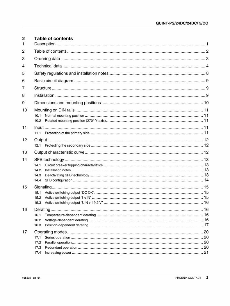
1 Description
DC/DC converter with SFB technology, dip-coated,
primary-switched, input: 24 V DC, output: 24 V DC,
output current: 5 A
QUINT-PS/24DC/24DC/ 5/CO
© PHOENIX CONTACT
Data sheet
QUINT DC/DC converter – superior system availability from
SFB technology
Compact DC/DC converters from the new QUINT POWER
generation maximize your system availability. With SFB
technology (Selective Fuse Breaking Technology), 6-fold
nominal current for 12 ms, it is possible to trigger even stan-
dard circuit breakers reliably and quickly. Faulty current
paths are switched off selectively, the fault is located, and
important system parts remain in operation. Comprehensive
diagnostics are provided through constant monitoring of the
input voltage, output voltage and output current. Preventive
function monitoring visualizes critical operating states and
indicates them to the controller before errors can occur.
The application fields for DC/DC converters are numerous
– Changing the voltage level
– Refreshing the output voltage for constant voltage at
the end of long cables
– Setup of independent supply systems by electrical iso-
lation
Features
– Wide-range voltage input
– Galvanic isolation
– Reverse polarity protection
– Preventive function monitoring
– Reliable starting of difficult loads with POWER BOOST
static power reserve
– Fast tripping of standard circuit breakers with dynamic
SFB technology power reserve
– High MTBF > 890,000 h (40°C)
Flexible use
– Dip coating enables use in oxidizing and sulfidizing
atmospheres with humidities of up to 100 %
– Adjustable output voltage
– Can be used in Class I, Division 2, Groups A, B, C, D
(Hazardous Location) ANSI-ISA 12.12
Make sure you always use the latest documentation.
It can be downloaded from the product at phoenixcontact.net/products.
105537_en_01 2014-02-13
QUINT-PS/24DC/24DC/ 5/CO
105537_en_01 PHOENIX CONTACT 2
2 Table of contents
1 Description .............................................................................................................................. 1
2 Table of contents ..................................................................................................................... 2
3 Ordering data .......................................................................................................................... 3
4 Technical data ......................................................................................................................... 4
5 Safety regulations and installation notes.................................................................................. 8
6 Basic circuit diagram ............................................................................................................... 9
7 Structure.................................................................................................................................. 9
8 Installation ............................................................................................................................... 9
9 Dimensions and mounting positions ...................................................................................... 10
10 Mounting on DIN rails ............................................................................................................ 11
10.1 Normal mounting position .................................................................................................... 11
10.2 Rotated mounting position (270° Y-axis).................................................................................. 11
11 Input ...................................................................................................................................... 11
11.1 Protection of the primary side ............................................................................................... 11
12 Output.................................................................................................................................... 12
12.1 Protecting the secondary side............................................................................................... 12
13 Output characteristic curve.................................................................................................... 12
14 SFB technology ..................................................................................................................... 13
14.1 Circuit breaker tripping characteristics .................................................................................... 13
14.2 Installation notes ............................................................................................................... 13
14.3 Deactivating SFB technology................................................................................................ 13
14.4 SFB configuration .............................................................................................................. 14
15 Signaling................................................................................................................................ 15
15.1 Active switching output “DC OK”............................................................................................ 15
15.2 Active switching output “I < IN” .............................................................................................. 15
15.3 Active switching output “UIN > 19.2 V” .................................................................................... 16
16 Derating................................................................................................................................. 16
16.1 Temperature-dependent derating .......................................................................................... 16
16.2 Voltage-dependent derating ................................................................................................. 16
16.3 Position-dependent derating................................................................................................. 17
17 Operating modes................................................................................................................... 20
17.1 Series operation ................................................................................................................ 20
17.2 Parallel operation............................................................................................................... 20
17.3 Redundant operation .......................................................................................................... 20
17.4 Increasing power ............................................................................................................... 21
QUINT-PS/24DC/24DC/ 5/CO
105537_en_01 PHOENIX CONTACT 3
Description Type Order No. Pcs. / Pkt.
Primary-switched QUINT DC/DC converter for DIN rail mounting, input: 24
V DC, output: 24 V DC/5 A, dip-coated PCB, with integrated SFB (selective
fuse breaking) technology, including mounted universal DIN rail adapter
UTA 107/30
QUINT-PS/24DC/24DC/ 5/CO 2320542 1
3 Ordering data
Accessories Type Order No. Pcs. / Pkt.
Primary-switched QUINT power supply for DIN rail mounting, input: 1-
phase, output: 24 V DC/10 A, with integrated SFB (selective fuse breaking)
technology, including mounted universal DIN rail adapter UTA 107
QUINT-PS/ 1AC/24DC/10 2866763 1
Primary-switched QUINT power supply for DIN rail mounting, input: 1-
phase, output: 24 V DC/10 A, dip-coated PCB, with integrated SFB (selec-
tive fuse breaking) technology, including mounted universal DIN rail
adapter UTA 107
QUINT-PS/ 1AC/24DC/10/CO 2320911 1
Primary-switched QUINT power supply for DIN rail mounting, input: 3-
phase, output: 24 V DC/10 A, with integrated SFB (selective fuse breaking)
technology, including mounted universal DIN rail adapter UTA 107
QUINT-PS/ 3AC/24DC/10 2866705 1
Active QUINT redundancy module for DIN rail mounting with integrated
SFB (selective fuse breaking) technology and monitoring functions, input:
24 V DC, output: 24 V DC/2 x 10 A or 1 x 20 A, including mounted universal
DIN rail adapter UTA 107/30
QUINT-ORING/24DC/2X10/1X20 2320173 1
Universal DIN rail adapter UTA 107/30 2320089 25
Universal wall adapter UWA 182/52 2938235 1
Assembly adapter for QUINT-PS... power supply on S7-300 rail QUINT-PS-ADAPTERS7/1 2938196 1
Thermomagnetic device circuit breaker, 1-pos., tripping characteristic
SFB, 1 PDT contact, plug for base element.
CB TM1 1A SFB P 2800836 1
Thermomagnetic device circuit breaker, 1-pos., tripping characteristic
SFB, 1 PDT contact, plug for base element.
CB TM1 2A SFB P 2800837 1
Thermomagnetic device circuit breaker, 1-pos., tripping characteristic
SFB, 1 PDT contact, plug for base element.
CB TM1 12A SFB P 2800844 1
Thermomagnetic device circuit breaker, 1-pos., tripping characteristic
SFB, 1 PDT contact, plug for base element.
CB TM1 16A SFB P 2800845 1
Our range of accessories is being continually extended, our current range can be found in the download area.
QUINT-PS/24DC/24DC/ 5/CO
105537_en_01 PHOENIX CONTACT 4
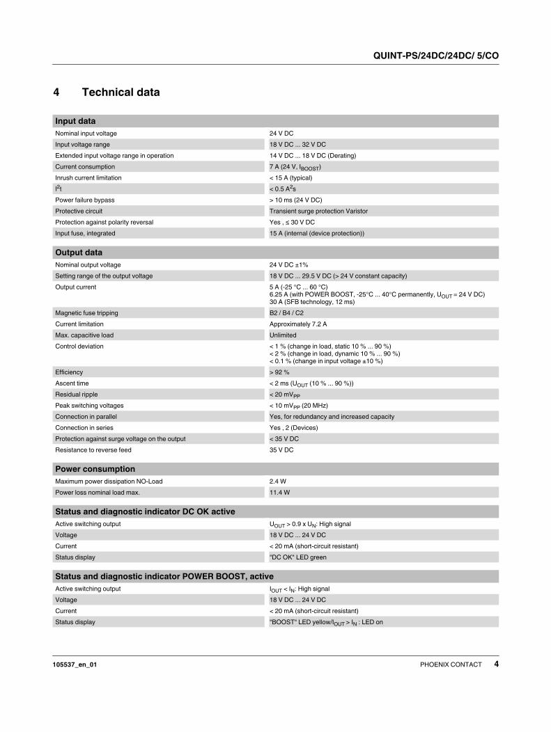
4 Technical data
Input data
Nominal input voltage 24 V DC
Input voltage range 18 V DC ... 32 V DC
Extended input voltage range in operation 14 V DC ... 18 V DC (Derating)
Current consumption 7 A (24 V, IBOOST)
Inrush current limitation < 15 A (typical)
I2t < 0.5 A
2s
Power failure bypass > 10 ms (24 V DC)
Protective circuit Transient surge protection Varistor
Protection against polarity reversal Yes , ≤ 30 V DC
Input fuse, integrated 15 A (internal (device protection))
Output data
Nominal output voltage 24 V DC ±1%
Setting range of the output voltage 18 V DC ... 29.5 V DC (> 24 V constant capacity)
Output current 5 A (-25 °C ... 60 °C)
6.25 A (with POWER BOOST, -25°C ... 40°C permanently, UOUT = 24 V DC)
30 A (SFB technology, 12 ms)
Magnetic fuse tripping B2 / B4 / C2
Current limitation Approximately 7.2 A
Max. capacitive load Unlimited
Control deviation < 1 % (change in load, static 10 % ... 90 %)
< 2 % (change in load, dynamic 10 % ... 90 %)
< 0.1 % (change in input voltage ±10 %)
Efficiency > 92 %
Ascent time < 2 ms (UOUT (10 % ... 90 %))
Residual ripple < 20 mVPP
Peak switching voltages < 10 mVPP (20 MHz)
Connection in parallel Yes, for redundancy and increased capacity
Connection in series Yes , 2 (Devices)
Protection against surge voltage on the output < 35 V DC
Resistance to reverse feed 35 V DC
Power consumption
Maximum power dissipation NO-Load 2.4 W
Power loss nominal load max. 11.4 W
Status and diagnostic indicator DC OK active
Active switching output UOUT > 0.9 x UN: High signal
Voltage 18 V DC ... 24 V DC
Current < 20 mA (short-circuit resistant)
Status display "DC OK" LED green
Status and diagnostic indicator POWER BOOST, active
Active switching output IOUT < IN: High signal
Voltage 18 V DC ... 24 V DC
Current < 20 mA (short-circuit resistant)
Status display "BOOST" LED yellow/IOUT > IN : LED on
QUINT-PS/24DC/24DC/ 5/CO
105537_en_01 PHOENIX CONTACT 5
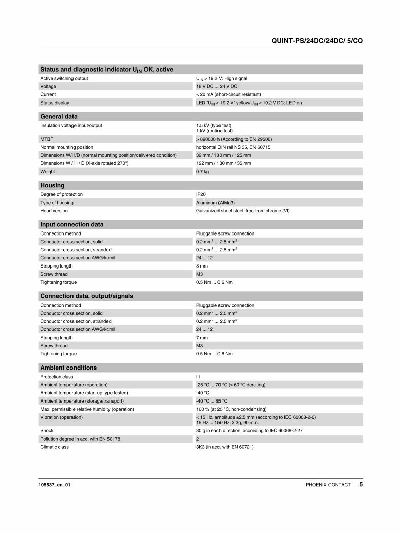
Status and diagnostic indicator UIN OK, active
Active switching output UIN > 19.2 V: High signal
Voltage 18 V DC ... 24 V DC
Current < 20 mA (short-circuit resistant)
Status display LED "UIN < 19.2 V" yellow/UIN < 19.2 V DC: LED on
General data
Insulation voltage input/output 1.5 kV (type test)
1 kV (routine test)
MTBF > 890000 h (According to EN 29500)
Normal mounting position horizontal DIN rail NS 35, EN 60715
Dimensions W/H/D (normal mounting position/delivered condition) 32 mm / 130 mm / 125 mm
Dimensions W / H / D (X-axis rotated 270°) 122 mm / 130 mm / 35 mm
Weight 0.7 kg
Housing
Degree of protection IP20
Type of housing Aluminum (AlMg3)
Hood version Galvanized sheet steel, free from chrome (VI)
Input connection data
Connection method Pluggable screw connection
Conductor cross section, solid 0.2 mm² ... 2.5 mm²
Conductor cross section, stranded 0.2 mm² ... 2.5 mm²
Conductor cross section AWG/kcmil 24 ... 12
Stripping length 8 mm
Screw thread M3
Tightening torque 0.5 Nm ... 0.6 Nm
Connection data, output/signals
Connection method Pluggable screw connection
Conductor cross section, solid 0.2 mm² ... 2.5 mm²
Conductor cross section, stranded 0.2 mm² ... 2.5 mm²
Conductor cross section AWG/kcmil 24 ... 12
Stripping length 7 mm
Screw thread M3
Tightening torque 0.5 Nm ... 0.6 Nm
Ambient conditions
Protection class III
Ambient temperature (operation) -25 °C ... 70 °C (> 60 °C derating)
Ambient temperature (start-up type tested) -40 °C
Ambient temperature (storage/transport) -40 °C ... 85 °C
Max. permissible relative humidity (operation) 100 % (at 25 °C, non-condensing)
Vibration (operation) < 15 Hz, amplitude ±2.5 mm (according to IEC 60068-2-6)
15 Hz ... 150 Hz, 2.3g, 90 min.
Shock 30 g in each direction, according to IEC 60068-2-27
Pollution degree in acc. with EN 50178 2
Climatic class 3K3 (in acc. with EN 60721)
QUINT-PS/24DC/24DC/ 5/CO
105537_en_01 PHOENIX CONTACT 6
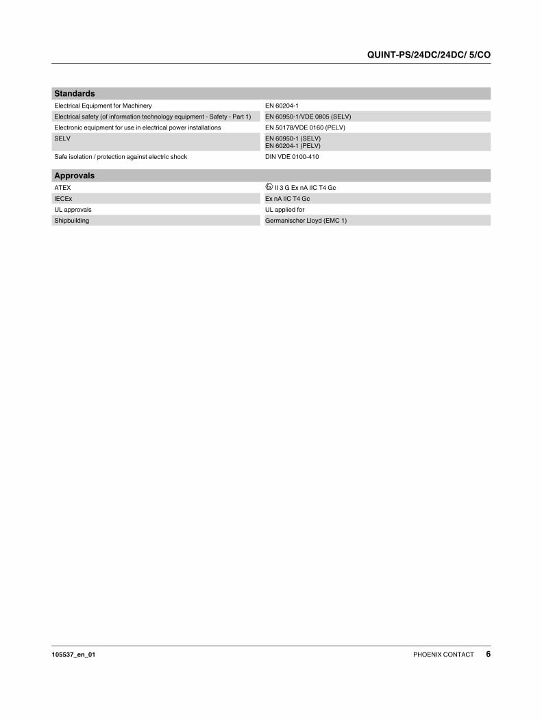
Standards
Electrical Equipment for Machinery EN 60204-1
Electrical safety (of information technology equipment - Safety - Part 1) EN 60950-1/VDE 0805 (SELV)
Electronic equipment for use in electrical power installations EN 50178/VDE 0160 (PELV)
SELV EN 60950-1 (SELV)
EN 60204-1 (PELV)
Safe isolation / protection against electric shock DIN VDE 0100-410
Approvals
ATEX II 3 G Ex nA IIC T4 Gc
IECEx Ex nA IIC T4 Gc
UL approvals UL applied for
Shipbuilding Germanischer Lloyd (EMC 1)
QUINT-PS/24DC/24DC/ 5/CO
105537_en_01 PHOENIX CONTACT 7
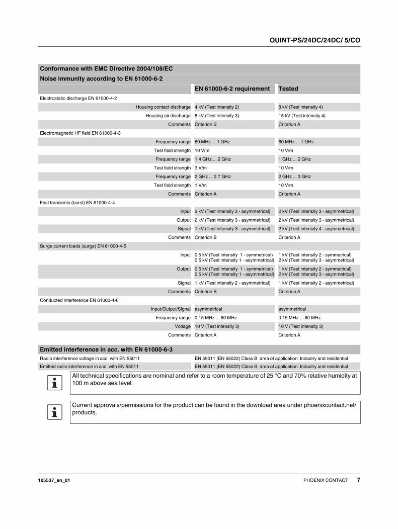
Conformance with EMC Directive 2004/108/EC
Noise immunity according to EN 61000-6-2
EN 61000-6-2 requirement Tested
Electrostatic discharge EN 61000-4-2
Housing contact discharge 4 kV (Test intensity 2) 8 kV (Test intensity 4)
Housing air discharge 8 kV (Test intensity 3) 15 kV (Test intensity 4)
Comments Criterion B Criterion A
Electromagnetic HF field EN 61000-4-3
Frequency range 80 MHz ... 1 GHz 80 MHz ... 1 GHz
Test field strength 10 V/m 10 V/m
Frequency range 1.4 GHz ... 2 GHz 1 GHz ... 2 GHz
Test field strength 3 V/m 10 V/m
Frequency range 2 GHz ... 2.7 GHz 2 GHz ... 3 GHz
Test field strength 1 V/m 10 V/m
Comments Criterion A Criterion A
Fast transients (burst) EN 61000-4-4
Input 2 kV (Test intensity 3 - asymmetrical) 2 kV (Test intensity 3 - asymmetrical)
Output 2 kV (Test intensity 3 - asymmetrical) 2 kV (Test intensity 3 - asymmetrical)
Signal 1 kV (Test intensity 3 - asymmetrical) 2 kV (Test intensity 4 - asymmetrical)
Comments Criterion B Criterion A
Surge current loads (surge) EN 61000-4-5
Input 0.5 kV (Test intensity 1 - symmetrical)
0.5 kV (Test intensity 1 - asymmetrical)
1 kV (Test intensity 2 - symmetrical)
2 kV (Test intensity 3 - asymmetrical)
Output 0.5 kV (Test intensity 1 - symmetrical)
0.5 kV (Test intensity 1 - asymmetrical)
1 kV (Test intensity 2 - symmetrical)
2 kV (Test intensity 3 - asymmetrical)
Signal 1 kV (Test intensity 2 - asymmetrical) 1 kV (Test intensity 2 - asymmetrical)
Comments Criterion B Criterion A
Conducted interference EN 61000-4-6
Input/Output/Signal asymmetrical asymmetrical
Frequency range 0.15 MHz ... 80 MHz 0.15 MHz ... 80 MHz
Voltage 10 V (Test intensity 3) 10 V (Test intensity 3)
Comments Criterion A Criterion A
Emitted interference in acc. with EN 61000-6-3
Radio interference voltage in acc. with EN 55011 EN 55011 (EN 55022) Class B, area of application: Industry and residential
Emitted radio interference in acc. with EN 55011 EN 55011 (EN 55022) Class B, area of application: Industry and residential
All technical specifications are nominal and refer to a room temperature of 25 °C and 70% relative humidity at
100 m above sea level.
Current approvals/permissions for the product can be found in the download area under phoenixcontact.net/
products.
QUINT-PS/24DC/24DC/ 5/CO
105537_en_01 PHOENIX CONTACT 8
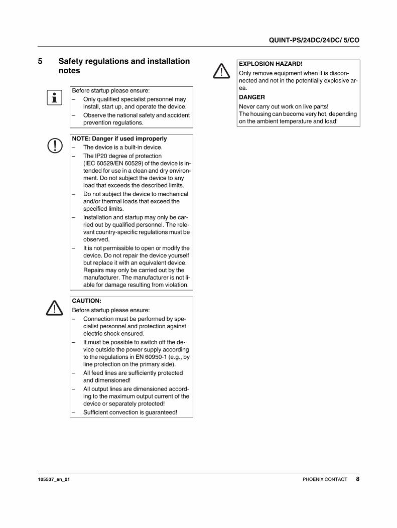
5 Safety regulations and installation
notes
Before startup please ensure:
– Only qualified specialist personnel may
install, start up, and operate the device.
– Observe the national safety and accident
prevention regulations.
NOTE: Danger if used improperly
– The device is a built-in device.
– The IP20 degree of protection
(IEC 60529/EN 60529) of the device is in-
tended for use in a clean and dry environ-
ment. Do not subject the device to any
load that exceeds the described limits.
– Do not subject the device to mechanical
and/or thermal loads that exceed the
specified limits.
– Installation and startup may only be car-
ried out by qualified personnel. The rele-
vant country-specific regulations must be
observed.
– It is not permissible to open or modify the
device. Do not repair the device yourself
but replace it with an equivalent device.
Repairs may only be carried out by the
manufacturer. The manufacturer is not li-
able for damage resulting from violation.
CAUTION:
Before startup please ensure:
– Connection must be performed by spe-
cialist personnel and protection against
electric shock ensured.
– It must be possible to switch off the de-
vice outside the power supply according
to the regulations in EN 60950-1 (e.g., by
line protection on the primary side).
– All feed lines are sufficiently protected
and dimensioned!
– All output lines are dimensioned accord-
ing to the maximum output current of the
device or separately protected!
– Sufficient convection is guaranteed!
EXPLOSION HAZARD!
Only remove equipment when it is discon-
nected and not in the potentially explosive ar-
ea.
DANGER
Never carry out work on live parts!
The housing can become very hot, depending
on the ambient temperature and load!
QUINT-PS/24DC/24DC/ 5/CO
105537_en_01 PHOENIX CONTACT 9
6 Basic circuit diagram
Figure 1 Basic circuit diagram
7 Structure
Figure 2 Function elements
1 DC input
2 DC output
3 Potentiometer 18 ... 29.5 V DC
4 LED "UIN < 19.2 V", yellow
5 "DC OK" LED, green
6 LED "BOOST", yellow
7 UIN > 19.2 V, active switching output
8 I < IIN, active switching output
9 DC OK, active switching output
10 SFB switch (left: SFB activated, right: SFB deactivated)
11 Strain relief for connecting cables
12 DIN rail adapter
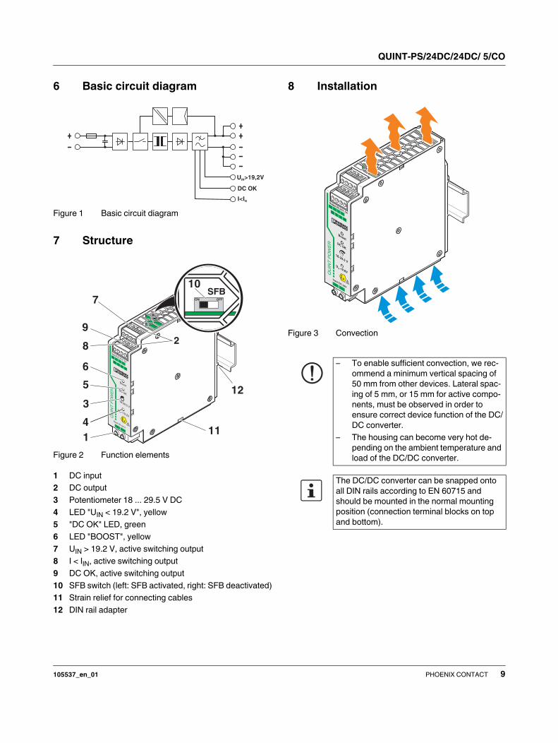
8 Installation
Figure 3 Convection
DC OK
U >19,2VIN
I<IN
QU
INT
PO
WE
R
+
-
Input DC 24 V
Output DC 24 V5A
-
-
++
DCOK Ι<
Ι N
DC OK
Boost
18-29,5 V
-
U>IN19,2 V
U<19.2V
IN
12
9
7
8
6
5
3
4
111
2
!
ON OFF
10SFB
– To enable sufficient convection, we rec-
ommend a minimum vertical spacing of
50 mm from other devices. Lateral spac-
ing of 5 mm, or 15 mm for active compo-
nents, must be observed in order to
ensure correct device function of the DC/
DC converter.
– The housing can become very hot de-
pending on the ambient temperature and
load of the DC/DC converter.
The DC/DC converter can be snapped onto
all DIN rails according to EN 60715 and
should be mounted in the normal mounting
position (connection terminal blocks on top
and bottom).
QU
INT
PO
WE
R
+-
Input DC 24V
Output DC 24 V5A
-
-
++
DCOK Ι<
Ι N
DC OK
Boost
18-29.5 V
-
U>IN19.2V
U<9.6V
IN
!
QUINT-PS/24DC/24DC/ 5/CO
105537_en_01 PHOENIX CONTACT 10
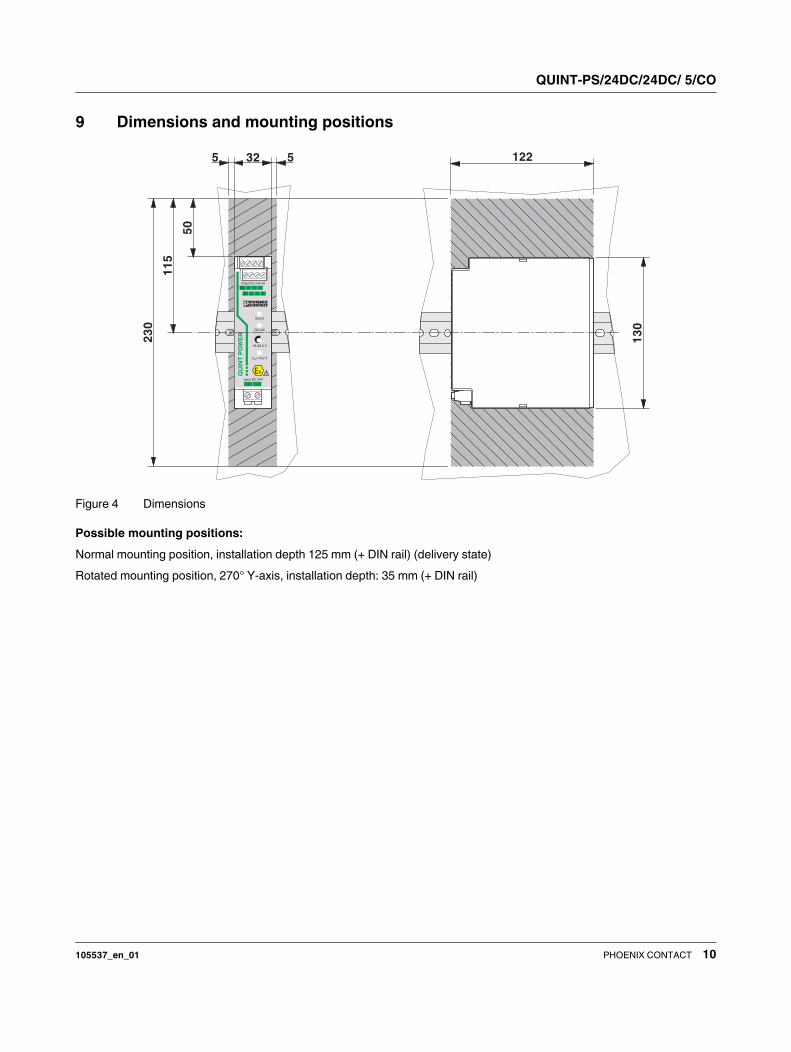
9 Dimensions and mounting positions
Figure 4 Dimensions
Possible mounting positions:
Normal mounting position, installation depth 125 mm (+ DIN rail) (delivery state)
Rotated mounting position, 270° Y-axis, installation depth: 35 mm (+ DIN rail)
QU
INT
PO
WE
R
+ -Input DC 24V
Output DC 24V 5ADC >IN
DCOK
Ι<Ι N
DC OK
Boost
18-29.5 V
19.2V
U <19.2 VIN
+ +
- --
!
32 55
13
0
122
50
11
5
23
0

QUINT-PS/24DC/24DC/ 5/CO
105537_en_01 PHOENIX CONTACT 11
10 Mounting on DIN rails
10.1 Normal mounting position
Assembly:
Position the DC/DC converter with the DIN rail guide on the
top edge of the DIN rail and snap it in by pushing downward.
Removing:
Pull back the snap-on catch using a screwdriver and detach
the DC/DC converter from the bottom edge of the DIN rail.
10.2 Rotated mounting position (270° Y-axis)
A rotated mounting position can be achieved for the DC/DC
converter by mounting the device on the DIN rail at a 270°
angle. Mount the DIN rail adapter (UTA 107/30) as shown in
the figure. No additional mounting material is required.
Mounting screws: Torx® T10 (0.8 Nm ... 0.9 Nm tightening
torque).
Figure 5 Rotated mounting position (270° Y-axis)
11 Input
Connection to the input voltage is established via the screw
connectors on the DC input screw connection.
The DC/DC converter converts a DC voltage of 18 ... 32 V
into adjustable, regulated, and electrically isolated output
voltage.
The DC/DC converter requires an input voltage of 18 V. Dur-
ing operation, this can drop down to 14 V, then observe the
voltage-dependent derating.
Figure 6 Input
11.1 Protection of the primary side
Installation of the DC/DC converter must correspond to EN
60950 regulations.
An internal fuse is provided for device protection. Additional
device protection is not required.
The connecting cables on the primary side should have
large cross sections to keep the voltage drops in the cables
as low as possible.
Other mounting positions are also possible.
Always observe position-dependent derating.
A B
B
A
NOTE: Device may be damaged
If an internal fuse trips, this is due to a device
fault. In this case, the DC/DC converter must
be inspected in the factory.
QU
INT
PO
WE
R
+-
Input DC 24V
Output DC 24 V5A
-
-
++
DCOK Ι<
Ι N
DC OK
Boost
18-29.5 V
-
U>IN19.2V
U<9.6V
IN
!
QUINT-PS/24DC/24DC/ 5/CO
105537_en_01 PHOENIX CONTACT 12
12 Output
Connection of the output voltage is established via the
screw connectors on the DC output screw connection.
The output voltage can be set on the potentiometer.
Figure 7 Output
12.1 Protecting the secondary side
The DC/DC converter is electronically short-circuit-proof
and idling-proof. In the event of an error, the output voltage
is limited. It must be ensured that all output cables are di-
mensioned accordingly for the maximum output current or
have separate protection.
The connecting cables on the secondary side should have
large cross sections to keep the voltage drops in the cables
as low as possible.
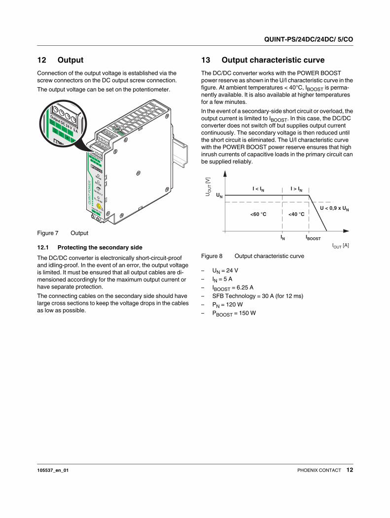
13 Output characteristic curve
The DC/DC converter works with the POWER BOOST
power reserve as shown in the U/I characteristic curve in the
figure. At ambient temperatures < 40°C, IBOOST is perma-
nently available. It is also available at higher temperatures
for a few minutes.
In the event of a secondary-side short circuit or overload, the
output current is limited to IBOOST. In this case, the DC/DC
converter does not switch off but supplies output current
continuously. The secondary voltage is then reduced until
the short circuit is eliminated. The U/I characteristic curve
with the POWER BOOST power reserve ensures that high
inrush currents of capacitive loads in the primary circuit can
be supplied reliably.
Figure 8 Output characteristic curve
– UN = 24 V
– IN = 5 A
– IBOOST = 6.25 A
– SFB Technology = 30 A (for 12 ms)
– PN = 120 W
– PBOOST = 150 W
QU
INT
PO
WE
R
+-
Input DC 24V
Output DC 24 V5A
-
-
++
DCOK Ι<
Ι N
DC OK
Boost
18-29.5 V
-
U>IN19.2V
U<9.6V
IN
!
I [A]OUT
U[V
]O
UT
UN
IN
I < IN
<60 °C
U < 0,9 x UN
I > IN
<40 °C
IBOOST
QUINT-PS/24DC/24DC/ 5/CO
105537_en_01 PHOENIX CONTACT 13
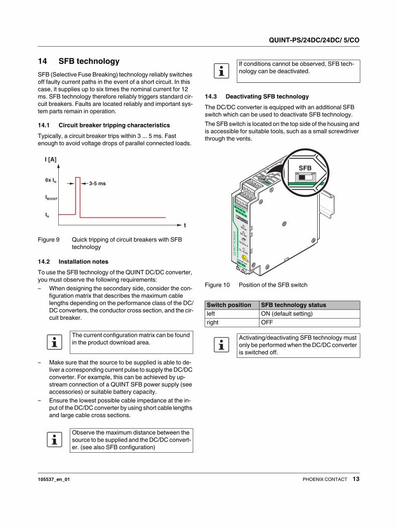
14 SFB technology
SFB (Selective Fuse Breaking) technology reliably switches
off faulty current paths in the event of a short circuit. In this
case, it supplies up to six times the nominal current for 12
ms. SFB technology therefore reliably triggers standard cir-
cuit breakers. Faults are located reliably and important sys-
tem parts remain in operation.
14.1 Circuit breaker tripping characteristics
Typically, a circuit breaker trips within 3 ... 5 ms. Fast
enough to avoid voltage drops of parallel connected loads.
Figure 9 Quick tripping of circuit breakers with SFB
technology
14.2 Installation notes
To use the SFB technology of the QUINT DC/DC converter,
you must observe the following requirements:
– When designing the secondary side, consider the con-
figuration matrix that describes the maximum cable
lengths depending on the performance class of the DC/
DC converters, the conductor cross section, and the cir-
cuit breaker.
– Make sure that the source to be supplied is able to de-
liver a corresponding current pulse to supply the DC/DC
converter. For example, this can be achieved by up-
stream connection of a QUINT SFB power supply (see
accessories) or suitable battery capacity.
– Ensure the lowest possible cable impedance at the in-
put of the DC/DC converter by using short cable lengths
and large cable cross sections.
14.3 Deactivating SFB technology
The DC/DC converter is equipped with an additional SFB
switch which can be used to deactivate SFB technology.
The SFB switch is located on the top side of the housing and
is accessible for suitable tools, such as a small screwdriver
through the vents.
Figure 10 Position of the SFB switch
The current configuration matrix can be found
in the product download area.
Observe the maximum distance between the
source to be supplied and the DC/DC convert-
er. (see also SFB configuration)
t
I [A]
6x IN
IBOOST
IN
3-5 ms
If conditions cannot be observed, SFB tech-
nology can be deactivated.
Switch position SFB technology status
left ON (default setting)
right OFF
Activating/deactivating SFB technology must
only be performed when the DC/DC converter
is switched off.
QU
INT
PO
WE
R
+-
Input DC 24V
Output DC 24 V5A
-
-
++
DCOK Ι<
Ι N
DC OK
Boost
18-29.5 V
-
U>IN19.2V
U<9.6V
IN
!
ON OFF
SFB
QUINT-PS/24DC/24DC/ 5/CO
105537_en_01 PHOENIX CONTACT 14
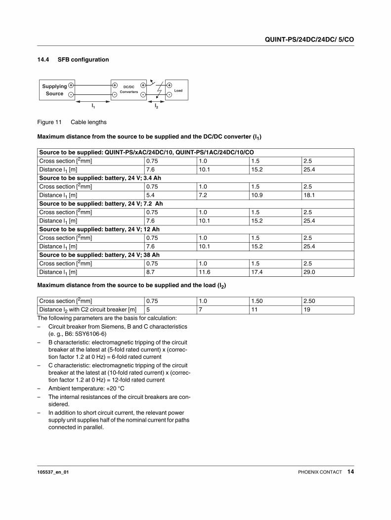
14.4 SFB configuration
Figure 11 Cable lengths
Maximum distance from the source to be supplied and the DC/DC converter (l1)
Maximum distance from the source to be supplied and the load (l2)
The following parameters are the basis for calculation:
– Circuit breaker from Siemens, B and C characteristics
(e. g., B6: 5SY6106-6)
– B characteristic: electromagnetic tripping of the circuit
breaker at the latest at (5-fold rated current) x (correc-
tion factor 1.2 at 0 Hz) = 6-fold rated current
– C characteristic: electromagnetic tripping of the circuit
breaker at the latest at (10-fold rated current) x (correc-
tion factor 1.2 at 0 Hz) = 12-fold rated current
– Ambient temperature: +20 °C
– The internal resistances of the circuit breakers are con-
sidered.
– In addition to short circuit current, the relevant power
supply unit supplies half of the nominal current for paths
connected in parallel.
+
-
+
-
+
-
+
-
l1 l2
Supplying
SourceLoad
DC/DC
Converters
Source to be supplied: QUINT-PS/xAC/24DC/10, QUINT-PS/1AC/24DC/10/CO
Cross section [2mm] 0.75 1.0 1.5 2.5
Distance l1 [m] 7.6 10.1 15.2 25.4
Source to be supplied: battery, 24 V; 3.4 Ah
Cross section [2mm] 0.75 1.0 1.5 2.5
Distance l1 [m] 5.4 7.2 10.9 18.1
Source to be supplied: battery, 24 V; 7.2 Ah
Cross section [2mm] 0.75 1.0 1.5 2.5
Distance l1 [m] 7.6 10.1 15.2 25.4
Source to be supplied: battery, 24 V; 12 Ah
Cross section [2mm] 0.75 1.0 1.5 2.5
Distance l1 [m] 7.6 10.1 15.2 25.4
Source to be supplied: battery, 24 V; 38 Ah
Cross section [2mm] 0.75 1.0 1.5 2.5
Distance l1 [m] 8.7 11.6 17.4 29.0
Cross section [2mm] 0.75 1.0 1.50 2.50
Distance l2 with C2 circuit breaker [m] 5 7 11 19
QUINT-PS/24DC/24DC/ 5/CO
105537_en_01 PHOENIX CONTACT 15
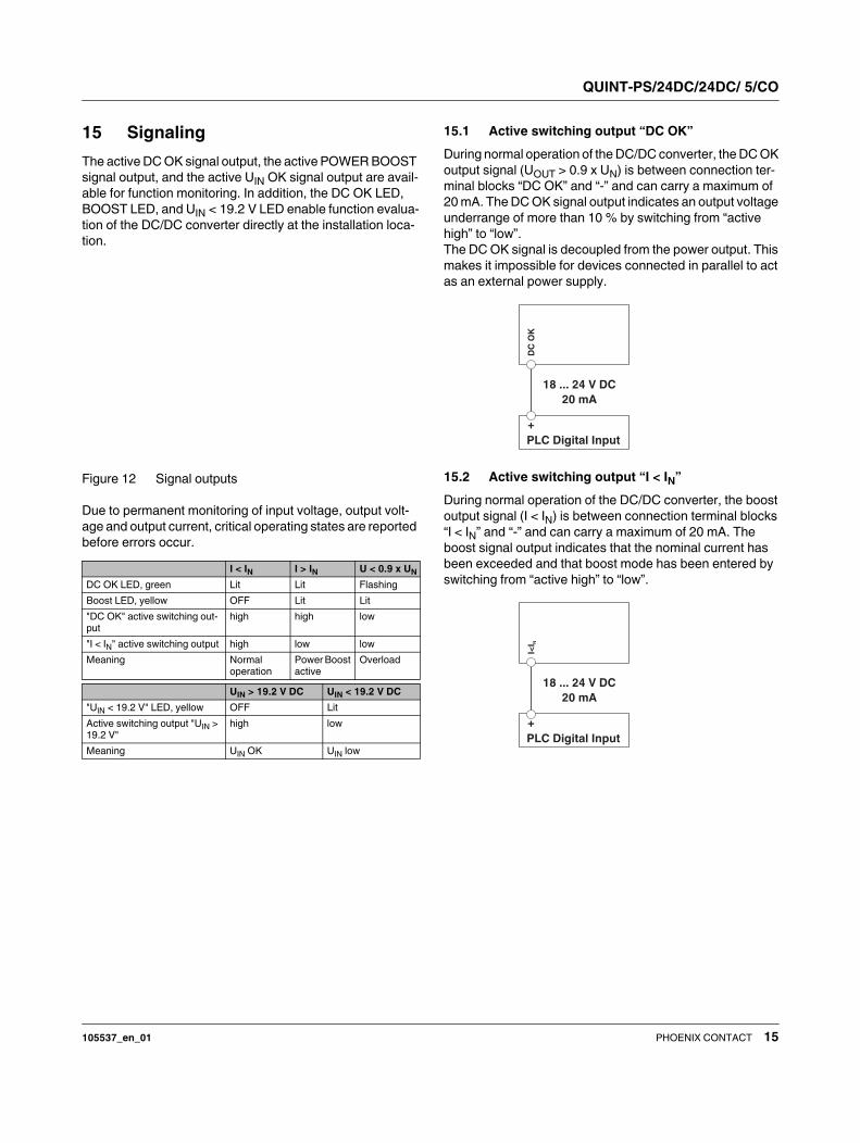
15 Signaling
The active DC OK signal output, the active POWER BOOST
signal output, and the active UIN OK signal output are avail-
able for function monitoring. In addition, the DC OK LED,
BOOST LED, and UIN < 19.2 V LED enable function evalua-
tion of the DC/DC converter directly at the installation loca-
tion.
Figure 12 Signal outputs
Due to permanent monitoring of input voltage, output volt-
age and output current, critical operating states are reported
before errors occur.
15.1 Active switching output “DC OK”
During normal operation of the DC/DC converter, the DC OK
output signal (UOUT > 0.9 x UN) is between connection ter-
minal blocks “DC OK” and “-” and can carry a maximum of
20 mA. The DC OK signal output indicates an output voltage
underrange of more than 10 % by switching from “active
high” to “low”.
The DC OK signal is decoupled from the power output. This
makes it impossible for devices connected in parallel to act
as an external power supply.
15.2 Active switching output “I < IN”
During normal operation of the DC/DC converter, the boost
output signal (I < IN) is between connection terminal blocks
“I < IN” and “-” and can carry a maximum of 20 mA. The
boost signal output indicates that the nominal current has
been exceeded and that boost mode has been entered by
switching from “active high” to “low”.
I < IN I > IN U < 0.9 x UN
DC OK LED, green Lit Lit Flashing
Boost LED, yellow OFF Lit Lit
"DC OK" active switching out-
put
high high low
"I < IN" active switching output high low low
Meaning Normal
operation
Power Boost
active
Overload
UIN > 19.2 V DC UIN < 19.2 V DC
"UIN < 19.2 V" LED, yellow OFF Lit
Active switching output "UIN >
19.2 V"
high low
Meaning UIN OK UIN low
18 ... 24 V DC
20 mA
DC
OK
PLC Digital Input
+
18 ... 24 V DC
20 mA
I<I N
PLC Digital Input
+
QUINT-PS/24DC/24DC/ 5/CO
105537_en_01 PHOENIX CONTACT 16
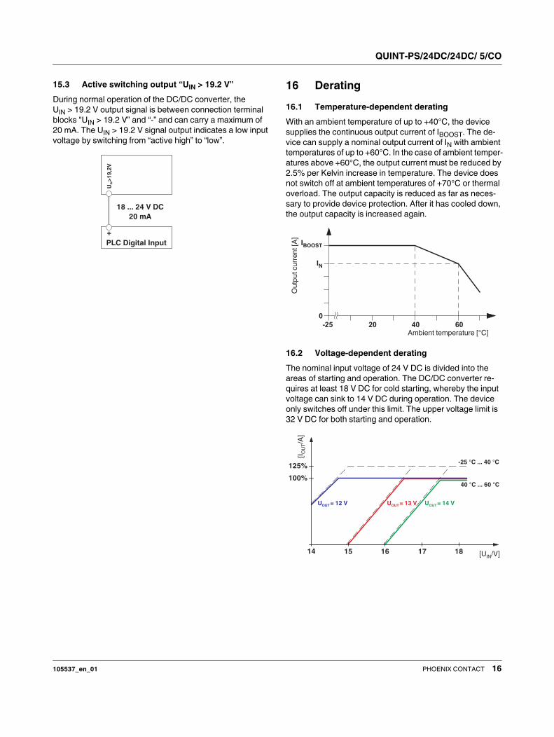
15.3 Active switching output “UIN > 19.2 V”
During normal operation of the DC/DC converter, the
UIN > 19.2 V output signal is between connection terminal
blocks "UIN > 19.2 V” and “-” and can carry a maximum of
20 mA. The UIN > 19.2 V signal output indicates a low input
voltage by switching from “active high” to “low”.
16 Derating
16.1 Temperature-dependent derating
With an ambient temperature of up to +40°C, the device
supplies the continuous output current of IBOOST. The de-
vice can supply a nominal output current of IN with ambient
temperatures of up to +60°C. In the case of ambient temper-
atures above +60°C, the output current must be reduced by
2.5% per Kelvin increase in temperature. The device does
not switch off at ambient temperatures of +70°C or thermal
overload. The output capacity is reduced as far as neces-
sary to provide device protection. After it has cooled down,
the output capacity is increased again.
16.2 Voltage-dependent derating
The nominal input voltage of 24 V DC is divided into the
areas of starting and operation. The DC/DC converter re-
quires at least 18 V DC for cold starting, whereby the input
voltage can sink to 14 V DC during operation. The device
only switches off under this limit. The upper voltage limit is
32 V DC for both starting and operation.
18 ... 24 V DC
20 mA
U>
19
,2V
IN
PLC Digital Input
+
-25
0
40 6020
IBOOST
IN
Ambient temperature [°C]
Ou
tpu
tc
urr
en
t[A
]
100%
125%
14 15 16 17 18 [U /V]IN
[I/A
]O
UT
= 12 VUOUT U = 13 VOUT U = 14 VOUT
-25 ℃ ... 40 ℃
40 ℃ ... 60 ℃
QUINT-PS/24DC/24DC/ 5/CO
105537_en_01 PHOENIX CONTACT 17
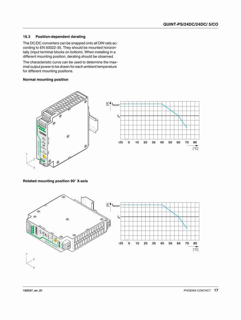
16.3 Position-dependent derating
The DC/DC converters can be snapped onto all DIN rails ac-
cording to EN 50022-35. They should be mounted horizon-
tally (input terminal blocks on bottom). When installing in a
different mounting position, derating should be observed.
The characteristic curve can be used to determine the max-
imal output power to be drawn for each ambient temperature
for different mounting positions.
Normal mounting position
Rotated mounting position 90° X-axis
Z
X
Y
QU
INT
PO
WE
R
+-
Input DC 24V
Output DC 24 V5A
-
-
++
DCOK Ι<
Ι N
DC OK
Boost
18-29.5 V
-
U>IN19.2V
U<19.2V
IN
!
IN
IBOOST
-25 0 10 20 30 40 50 60 70 80
[°C]
[A]
Z
X
Y
QUINT POW
ER
+-
Inp
ut
DC
24
V
Ou
tpu
tD
C2
4V
5A
--
++
DC
OK
Ι < ΙN
DC
OK
Bo
os
t
18
-29
.5 V
-U
>IN
19
.2V
U<
19
.2V
IN
!
IN
IBOOST
-25 0 10 20 30 40 50 60 70 80
[°C]
[A]
QUINT-PS/24DC/24DC/ 5/CO
105537_en_01 PHOENIX CONTACT 18
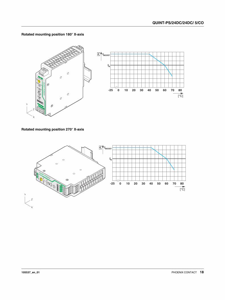
Rotated mounting position 180° X-axis
Rotated mounting position 270° X-axis
QU
INT
PO
WE
R
+-
Input DC 24V
OutputDC24V5A
-
-
++
DCOKΙ<
ΙN
DC OK
Boost
18-29.5 V
-
U>IN
19.2V
U<19.2V
IN
!
Z
X
Y
IN
IBOOST
-25 0 10 20 30 40 50 60 70 80
[°C][A
]
Z
X
Y
QUINT POWER
+-
Inp
ut D
C 2
4V
Ou
tpu
tD
C2
4V
5A
--
++
DC
OK
Ι<Ι
N
DC
OK
Bo
os
t
18
-29
.5 V
-U
>IN
19
.2V
U<
19
.2V
IN
!
IN
IBOOST
-25 0 10 20 30 40 50 60 70 80
[°C]
[A]
QUINT-PS/24DC/24DC/ 5/CO
105537_en_01 PHOENIX CONTACT 19
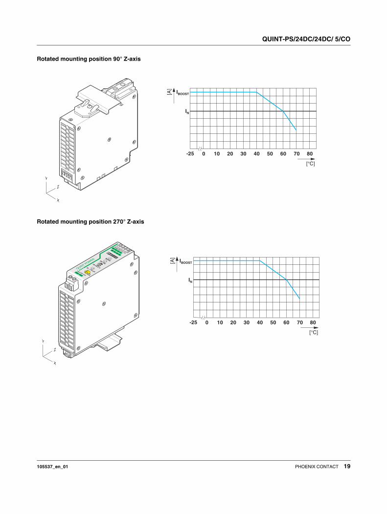
Rotated mounting position 90° Z-axis
Rotated mounting position 270° Z-axis
IN
IBOOST
-25 0 10 20 30 40 50 60 70 80
[°C][A
]
Z
X
Y
QUINT POW
ER
+-
Input DC 24V
Output DC 24 V5A
-
-++
DCOKΙ<Ι N
DC OK
Boost
18-29.5 V
-
U>IN19.2V
U<19.2V
IN
!
IN
IBOOST
-25 0 10 20 30 40 50 60 70 80
[°C]
[A]
Z
X
Y
QUINT-PS/24DC/24DC/ 5/CO
105537_en_01 PHOENIX CONTACT 20
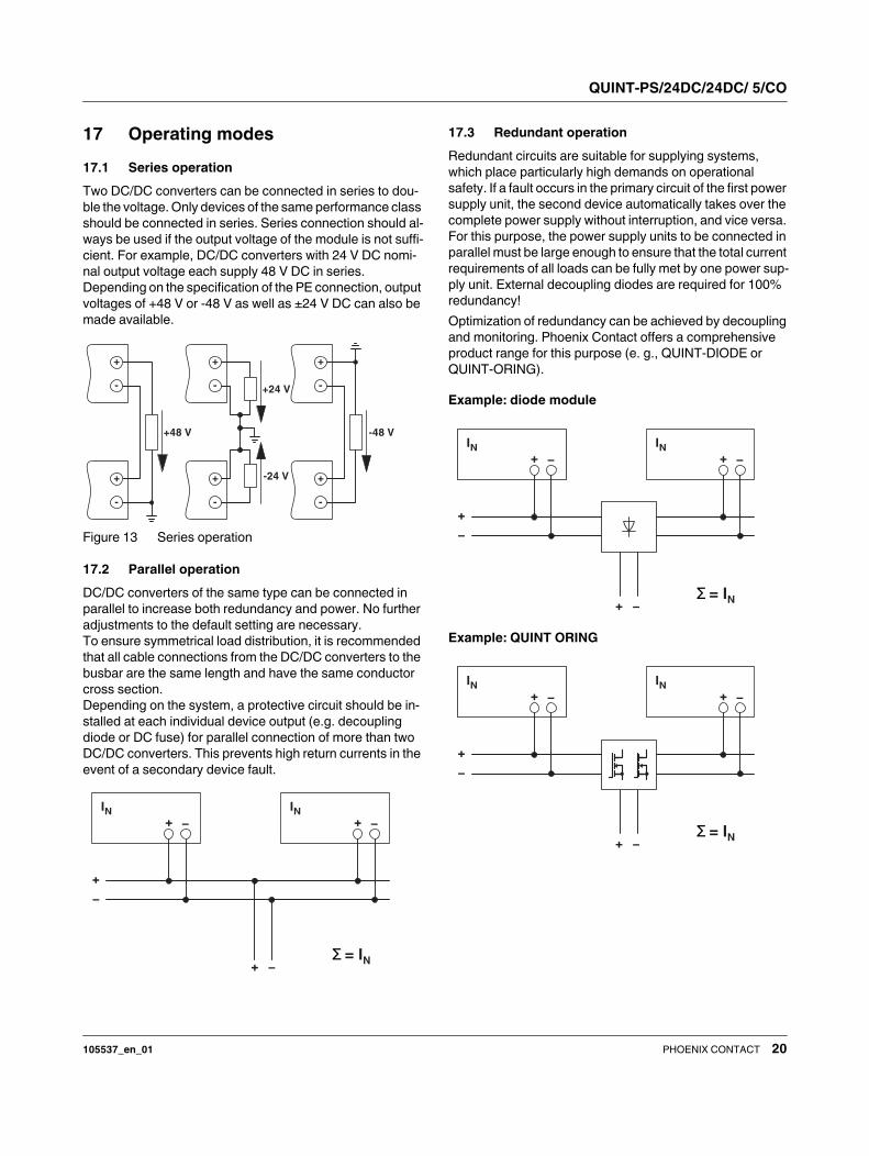
17 Operating modes
17.1 Series operation
Two DC/DC converters can be connected in series to dou-
ble the voltage. Only devices of the same performance class
should be connected in series. Series connection should al-
ways be used if the output voltage of the module is not suffi-
cient. For example, DC/DC converters with 24 V DC nomi-
nal output voltage each supply 48 V DC in series.
Depending on the specification of the PE connection, output
voltages of +48 V or -48 V as well as ±24 V DC can also be
made available.
Figure 13 Series operation
17.2 Parallel operation
DC/DC converters of the same type can be connected in
parallel to increase both redundancy and power. No further
adjustments to the default setting are necessary.
To ensure symmetrical load distribution, it is recommended
that all cable connections from the DC/DC converters to the
busbar are the same length and have the same conductor
cross section.
Depending on the system, a protective circuit should be in-
stalled at each individual device output (e.g. decoupling
diode or DC fuse) for parallel connection of more than two
DC/DC converters. This prevents high return currents in the
event of a secondary device fault.
17.3 Redundant operation
Redundant circuits are suitable for supplying systems,
which place particularly high demands on operational
safety. If a fault occurs in the primary circuit of the first power
supply unit, the second device automatically takes over the
complete power supply without interruption, and vice versa.
For this purpose, the power supply units to be connected in
parallel must be large enough to ensure that the total current
requirements of all loads can be fully met by one power sup-
ply unit. External decoupling diodes are required for 100%
redundancy!
Optimization of redundancy can be achieved by decoupling
and monitoring. Phoenix Contact offers a comprehensive
product range for this purpose (e. g., QUINT-DIODE or
QUINT-ORING).
Example: diode module
Example: QUINT ORING
+48 V -48 V
+24 V
-24 V+
-
+
-
+
-
+
-
+
-
+
-
+
IN− +
IN−
+
+
−
−Σ = IN
+
IN− +
IN−
+
+
−
−Σ = IN
+
IN− +
IN−
+
+
−
−Σ = IN
QUINT-PS/24DC/24DC/ 5/CO
105537_en_01 21PHOENIX CONTACT GmbH & Co. KG • 32823 Blomberg • Germany
phoenixcontact.com
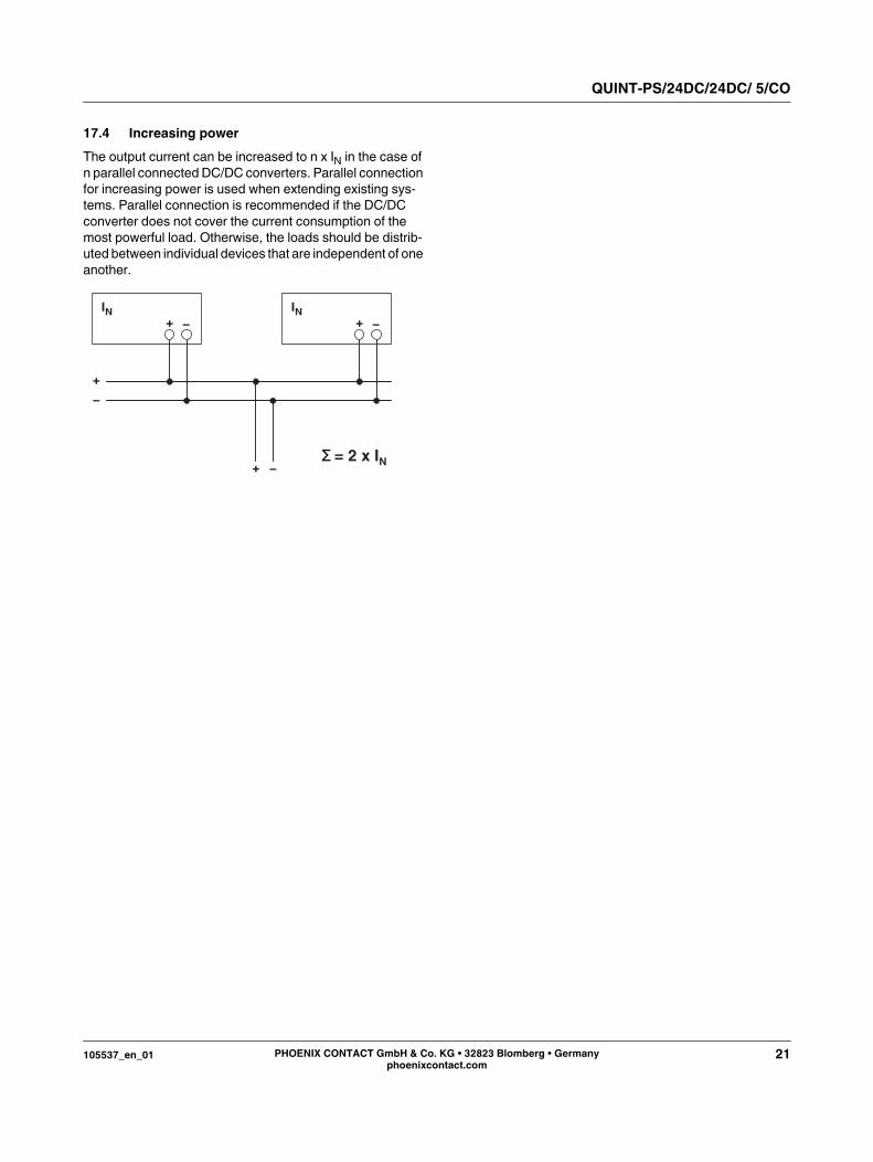
17.4 Increasing power
The output current can be increased to n x IN in the case of
n parallel connected DC/DC converters. Parallel connection
for increasing power is used when extending existing sys-
tems. Parallel connection is recommended if the DC/DC
converter does not cover the current consumption of the
most powerful load. Otherwise, the loads should be distrib-
uted between individual devices that are independent of one
another.
+
IN− +
IN−
+
+
−
−Σ = 2 x IN