Embed Size (px)
Citation preview

Department of Computer Science and Engineering
CS6004 Computer Networking
Subject Notes: UNIT-II
DATA LINK LAYER: NEED
Data Link Layer is second layer of OSI Layered Model. This layer is one of the most complicated layers and
has complex functionalities and liabilities. Data link layer hides the details of underlying hardware and
represents itself to upper layer as the medium to communicate.
Data link layer works between two hosts which are directly connected in some sense. This direct
connection could be point to point or broadcast. Data link layer is responsible for converting data stream
to signals bit by bit and to send that over the underlying hardware.
Fig. 2.1 Seven Layer Architecture
Data link layer has two sub-layers:
• Logical Link Control: It deals with protocols, flow-control, and error control
• Media Access Control: It deals with actual control of media
DATA LINK LAYER: SERVICE PROVIDED
• Encapsulation of network layer data packets into frames.
• Frame synchronization.
• Error Control
• Flow control, in addition to the one provided on the transport layer.
• LAN switching (packet switching) including MAC filtering and spanning tree protocol
• Data packet queuing or scheduling
• Store-and-forward switching or cut-through switching
DATA LINK LAYER: FRAMING
Since the physical layer merely accepts and transmits a stream of bits without any regard to meaning or
structure, it is up to the data link layer to create and recognize frame boundaries. This can be accomplished
by attaching special bit patterns to the beginning and end of the frame. If these bit patterns can
accidentally occur in data, special care must be taken to make sure these patterns are not incorrectly
interpreted as frame delimiters. The four framing methods that are widely used are
• Character count
• Starting and ending characters, with character stuffing
• Starting and ending flags, with bit stuffing
Fig. 2.2 Data Link Layer: Framing
Character Count
Page no: 1
This method uses a field in the header to specify the number of characters in the frame. When the data
link layer at the destination sees the character count, it knows how many characters follow, and hence
where the end of the frame is. The disadvantage is that if the count is garbled by a transmission error, the
destination will lose synchronization and will be unable to locate the start of the next frame. So, this
method is rarely used.
Character stuffing
In the second method, each frame starts with the ASCII character sequence DLE STX and ends with the
sequence DLE ETX. This method overcomes the drawbacks of the character count method. However,
character stuffing is closely associated with 8-bit characters and this is a major hurdle in transmitting
arbitrary sized characters.
Bit stuffing
The third method allows data frames to contain an arbitrary number of bits and allows character codes
with an arbitrary number of bits per character. At the start and end of each frame is a flag byte consisting
of the special bit pattern 01111110. Whenever the sender's data link layer encounters five consecutive 1s
in the data, it automatically stuffs a zero bit into the outgoing bit stream. This technique is called bit
stuffing
Physical layer coding violations
The final framing method is physical layer coding violations and is applicable to networks in which the
encoding on the physical medium contains some redundancy. In such cases normally, a 1 bit is a high-low
pair and a 0 bit is a low-high pair. The combinations of low-low and high-high which are not used for data
may be used for marking frame boundaries.
DATALINK LAYER: FLOW CONTROL
Flow control coordinates that amount of data that can be sent before receiving acknowledgement.
• It is one of the most important duties of the data link layer.
• Flow control tells the sender how much data to send.
• It makes the sender wait for some sort of an acknowledgment (ACK) before continuing to send more
data.
• Flow Control Techniques: Stop-and-wait, and Sliding Window
DATA LINK LAYER: ERROR CONTROL
Error control in the data link layer is based on ARQ (automatic repeat request), which is the retransmission
of data.
• The term error control refers to methods of error detection and retransmission.
• Anytime an error is detected in an exchange, specified frames are retransmitted. This process is
called ARQ.
To ensure reliable communication, there needs to exist flow control (managing the amount of data the
sender sends), and error control (that data arrives at the destination error free).
• Flow and error control needs to be done at several layers.
• For node-to-node links, flow and error control is carried out in the data-link layer.
• For end-point to end-point, flow and error control is carried out in the transport layer.
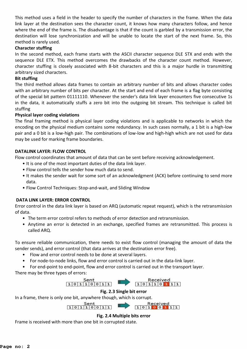
There may be three types of errors:
Fig. 2.3 Single bit error
In a frame, there is only one bit, anywhere though, which is corrupt.
Fig. 2.4 Multiple bits error
Frame is received with more than one bit in corrupted state.
Page no: 2
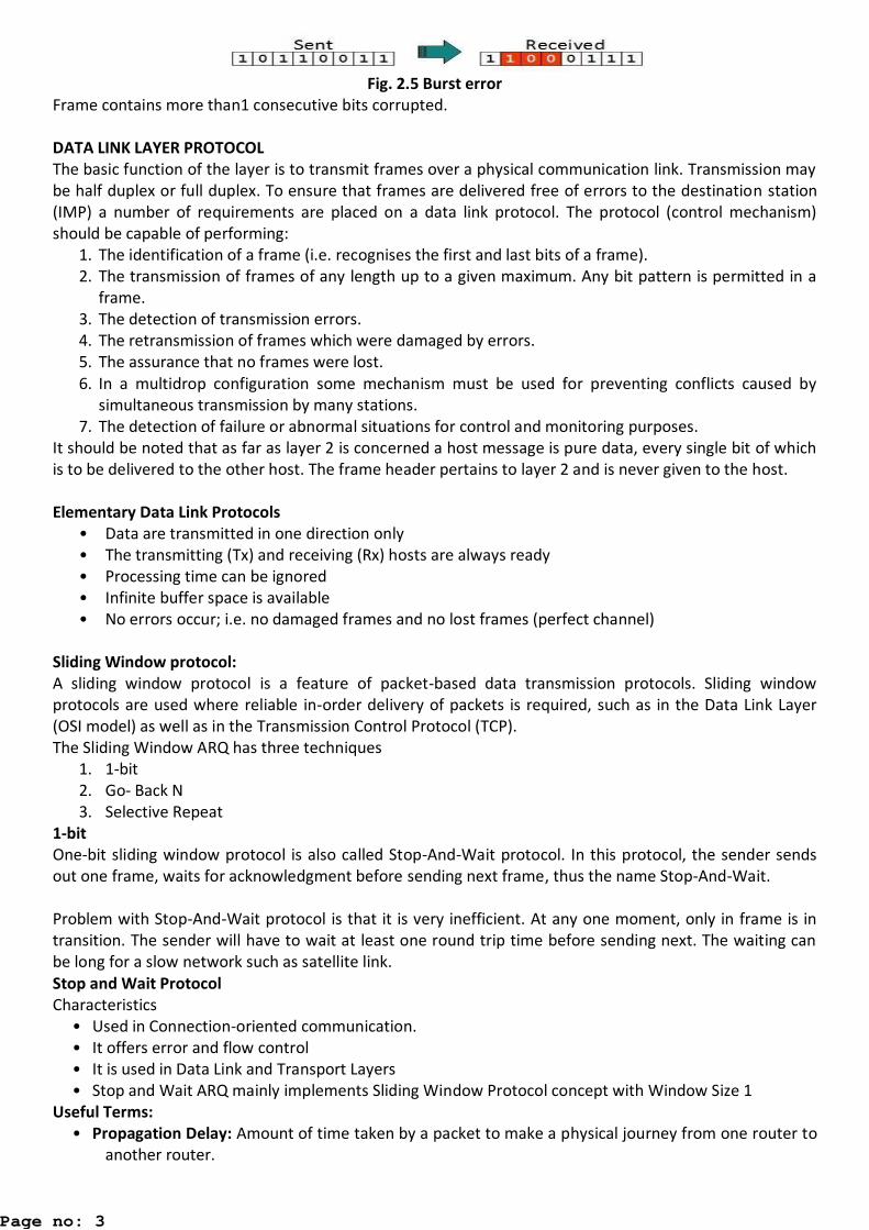
Fig. 2.5 Burst error
Frame contains more than1 consecutive bits corrupted.
DATA LINK LAYER PROTOCOL
The basic function of the layer is to transmit frames over a physical communication link. Transmission may
be half duplex or full duplex. To ensure that frames are delivered free of errors to the destination station
(IMP) a number of requirements are placed on a data link protocol. The protocol (control mechanism)
should be capable of performing:
1. The identification of a frame (i.e. recognises the first and last bits of a frame).
2. The transmission of frames of any length up to a given maximum. Any bit pattern is permitted in a
frame.
3. The detection of transmission errors.
4. The retransmission of frames which were damaged by errors.
5. The assurance that no frames were lost.
6. In a multidrop configuration some mechanism must be used for preventing conflicts caused by
simultaneous transmission by many stations.
7. The detection of failure or abnormal situations for control and monitoring purposes.
It should be noted that as far as layer 2 is concerned a host message is pure data, every single bit of which
is to be delivered to the other host. The frame header pertains to layer 2 and is never given to the host.
Elementary Data Link Protocols
• Data are transmitted in one direction only
• The transmitting (Tx) and receiving (Rx) hosts are always ready
• Processing time can be ignored
• Infinite buffer space is available
• No errors occur; i.e. no damaged frames and no lost frames (perfect channel)
Sliding Window protocol:
A sliding window protocol is a feature of packet-based data transmission protocols. Sliding window
protocols are used where reliable in-order delivery of packets is required, such as in the Data Link Layer
(OSI model) as well as in the Transmission Control Protocol (TCP).
The Sliding Window ARQ has three techniques
1. 1-bit
2. Go- Back N
3. Selective Repeat
1-bit
One-bit sliding window protocol is also called Stop-And-Wait protocol. In this protocol, the sender sends
out one frame, waits for acknowledgment before sending next frame, thus the name Stop-And-Wait.
Problem with Stop-And-Wait protocol is that it is very inefficient. At any one moment, only in frame is in
transition. The sender will have to wait at least one round trip time before sending next. The waiting can
be long for a slow network such as satellite link.
Stop and Wait Protocol
Characteristics
• Used in Connection-oriented communication.
• It offers error and flow control
• It is used in Data Link and Transport Layers
• Stop and Wait ARQ mainly implements Sliding Window Protocol concept with Window Size 1
Useful Terms:
• Propagation Delay: Amount of time taken by a packet to make a physical journey from one router to
another router.
Page no: 3
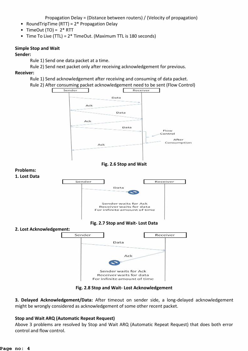
Propagation Delay = (Distance between routers) / (Velocity of propagation)
• RoundTripTime (RTT) = 2* Propagation Delay
• TimeOut (TO) = 2* RTT
• Time To Live (TTL) = 2* TimeOut. (Maximum TTL is 180 seconds)
Simple Stop and Wait
Sender:
Rule 1) Send one data packet at a time.
Rule 2) Send next packet only after receiving acknowledgement for previous.
Receiver:
Rule 1) Send acknowledgement after receiving and consuming of data packet.
Rule 2) After consuming packet acknowledgement need to be sent (Flow Control)
Fig. 2.6 Stop and Wait
Problems:
1. Lost Data
Fig. 2.7 Stop and Wait- Lost Data
2. Lost Acknowledgement:
Fig. 2.8 Stop and Wait- Lost Acknowledgement
3. Delayed Acknowledgement/Data: After timeout on sender side, a long-delayed acknowledgement
might be wrongly considered as acknowledgement of some other recent packet.
Stop and Wait ARQ (Automatic Repeat Request)
Above 3 problems are resolved by Stop and Wait ARQ (Automatic Repeat Request) that does both error
control and flow control.
Page no: 4
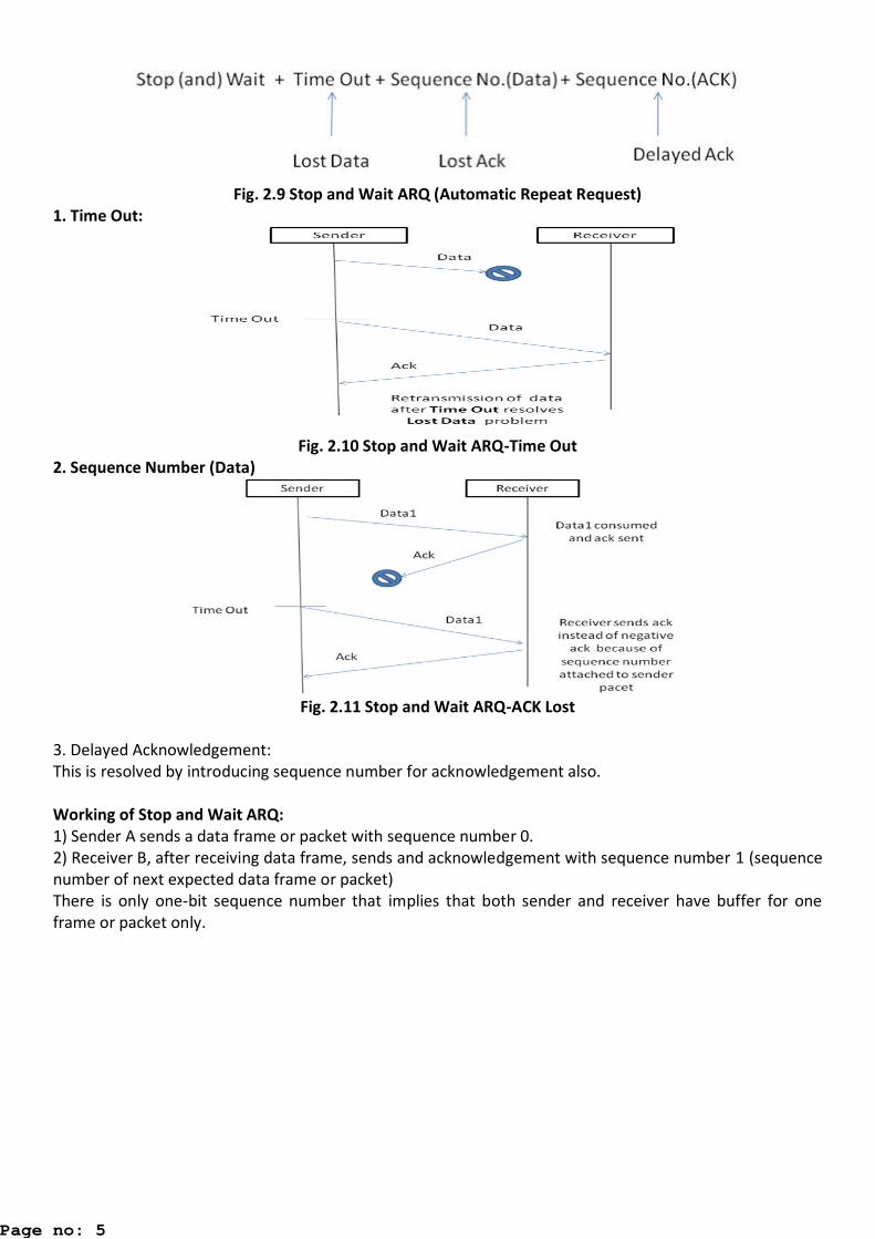
Fig. 2.9 Stop and Wait ARQ (Automatic Repeat Request)
1. Time Out:
Fig. 2.10 Stop and Wait ARQ-Time Out
2. Sequence Number (Data)
Fig. 2.11 Stop and Wait ARQ-ACK Lost
3. Delayed Acknowledgement:
This is resolved by introducing sequence number for acknowledgement also.
Working of Stop and Wait ARQ:
1) Sender A sends a data frame or packet with sequence number 0.
2) Receiver B, after receiving data frame, sends and acknowledgement with sequence number 1 (sequence
number of next expected data frame or packet)
There is only one-bit sequence number that implies that both sender and receiver have buffer for one
frame or packet only.
Page no: 5
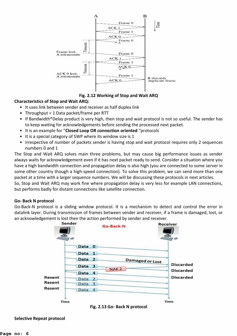
Fig. 2.12 Working of Stop and Wait ARQ
Characteristics of Stop and Wait ARQ:
• It uses link between sender and receiver as half duplex link
• Throughput = 1 Data packet/frame per RTT
• If Bandwidth*Delay product is very high, then stop and wait protocol is not so useful. The sender has
to keep waiting for acknowledgements before sending the processed next packet.
• It is a e a ple for “Closed Loop OR connection oriented “protocols
• It is a special category of SWP where its window size is 1
• Irrespective of number of packets sender is having stop and wait protocol requires only 2 sequences
numbers 0 and 1
The Stop and Wait ARQ solves main three problems, but may cause big performance issues as sender
always waits for acknowledgement even if it has next packet ready to send. Consider a situation where you
have a high bandwidth connection and propagation delay is also high (you are connected to some server in
some other country though a high-speed connection). To solve this problem, we can send more than one
packet at a time with a larger sequence numbers. We will be discussing these protocols in next articles.
So, Stop and Wait ARQ may work fine where propagation delay is very less for example LAN connections,
but performs badly for distant connections like satellite connection.
Go- Back N protocol
Go-Back-N protocol is a sliding window protocol. It is a mechanism to detect and control the error in
datalink layer. During transmission of frames between sender and receiver, if a frame is damaged, lost, or
an acknowledgement is lost then the action performed by sender and receiver.
Fig. 2.13 Go- Back N protocol
Selective Repeat protocol
Page no: 6
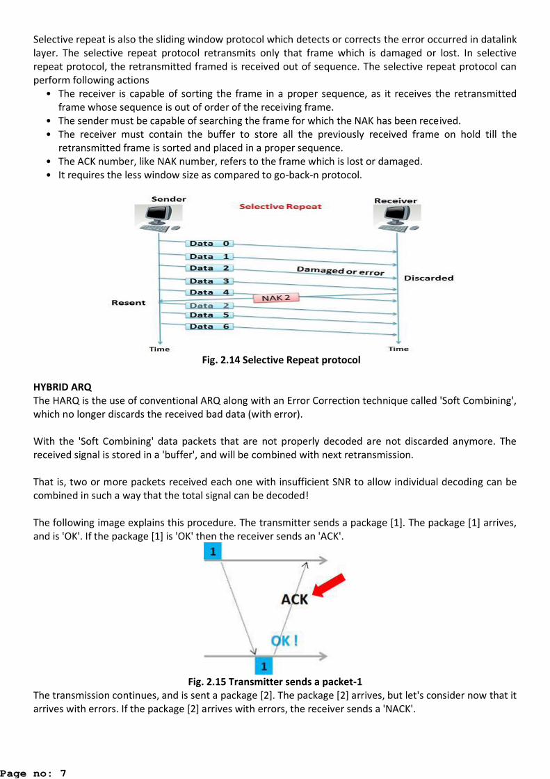
Selective repeat is also the sliding window protocol which detects or corrects the error occurred in datalink
layer. The selective repeat protocol retransmits only that frame which is damaged or lost. In selective
repeat protocol, the retransmitted framed is received out of sequence. The selective repeat protocol can
perform following actions
• The receiver is capable of sorting the frame in a proper sequence, as it receives the retransmitted
frame whose sequence is out of order of the receiving frame.
• The sender must be capable of searching the frame for which the NAK has been received.
• The receiver must contain the buffer to store all the previously received frame on hold till the
retransmitted frame is sorted and placed in a proper sequence.
• The ACK number, like NAK number, refers to the frame which is lost or damaged.
• It requires the less window size as compared to go-back-n protocol.
Fig. 2.14 Selective Repeat protocol
HYBRID ARQ
The HARQ is the use of conventional ARQ along with an Error Correction technique called 'Soft Combining',
which no longer discards the received bad data (with error).
With the 'Soft Combining' data packets that are not properly decoded are not discarded anymore. The
received signal is stored in a 'buffer', and will be combined with next retransmission.
That is, two or more packets received each one with insufficient SNR to allow individual decoding can be
combined in such a way that the total signal can be decoded!
The following image explains this procedure. The transmitter sends a package [1]. The package [1] arrives,
and is 'OK'. If the package [1] is 'OK' then the receiver sends an 'ACK'.
Fig. 2.15 Transmitter sends a packet-1
The transmission continues, and is sent a package [2]. The package [2] arrives, but let's consider now that it
arrives with errors. If the package [2] arrives with errors, the receiver sends a 'NACK'.
Page no: 7
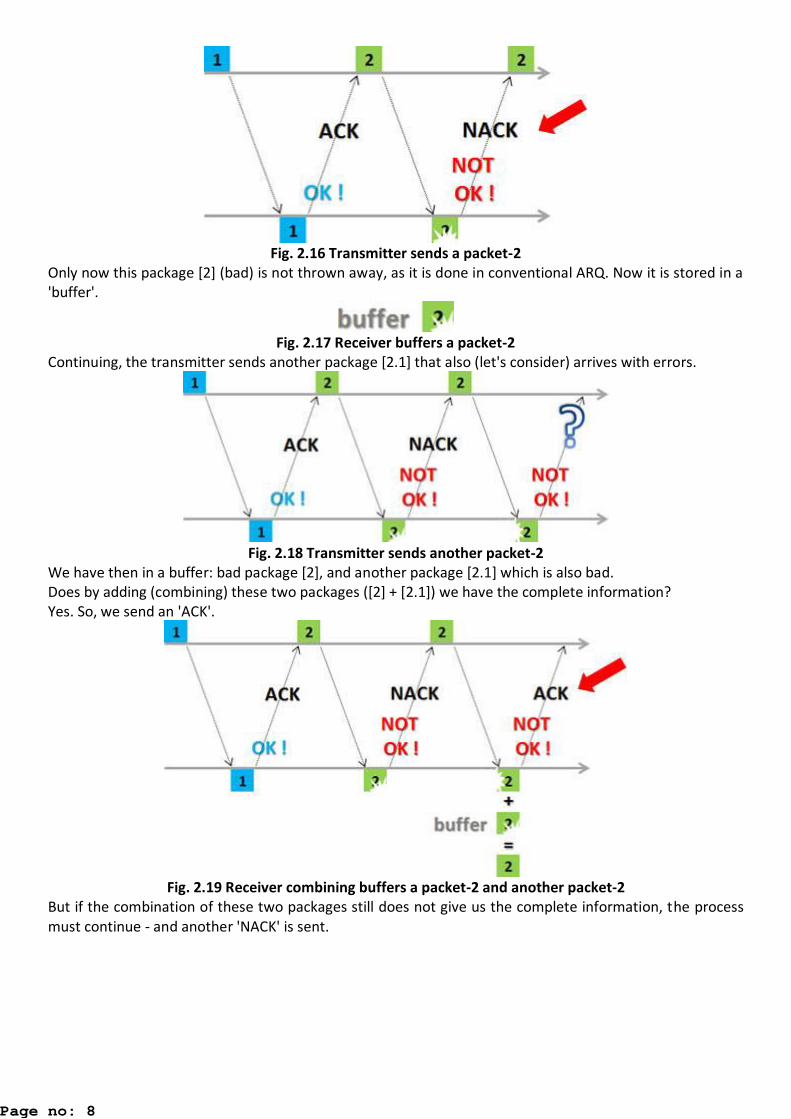
Fig. 2.16 Transmitter sends a packet-2
Only now this package [2] (bad) is not thrown away, as it is done in conventional ARQ. Now it is stored in a
'buffer'.
Fig. 2.17 Receiver buffers a packet-2
Continuing, the transmitter sends another package [2.1] that also (let's consider) arrives with errors.
Fig. 2.18 Transmitter sends another packet-2
We have then in a buffer: bad package [2], and another package [2.1] which is also bad.
Does by adding (combining) these two packages ([2] + [2.1]) we have the complete information?
Yes. So, we send an 'ACK'.
Fig. 2.19 Receiver combining buffers a packet-2 and another packet-2
But if the combination of these two packages still does not give us the complete information, the process
must continue - and another 'NACK' is sent.
Page no: 8
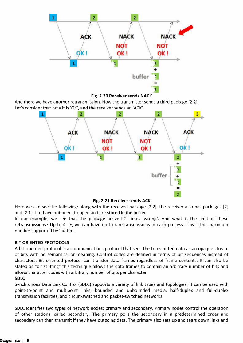
Fig. 2.20 Receiver sends NACK
And there we have another retransmission. Now the transmitter sends a third package [2.2].
Let's consider that now it is 'OK', and the receiver sends an 'ACK'.
Fig. 2.21 Receiver sends ACK
Here we can see the following: along with the received package [2.2], the receiver also has packages [2]
and [2.1] that have not been dropped and are stored in the buffer.
In our example, we see that the package arrived 2 times 'wrong'. And what is the limit of these
retransmissions? Up to 4. IE, we can have up to 4 retransmissions in each process. This is the maximum
number supported by 'buffer'.
BIT ORIENTED PROTOCOLS
A bit-oriented protocol is a communications protocol that sees the transmitted data as an opaque stream
of bits with no semantics, or meaning. Control codes are defined in terms of bit sequences instead of
characters. Bit oriented protocol can transfer data frames regardless of frame contents. It can also be
stated as "bit stuffing" this technique allows the data frames to contain an arbitrary number of bits and
allows character codes with arbitrary number of bits per character.
SDLC
Synchronous Data Link Control (SDLC) supports a variety of link types and topologies. It can be used with
point-to-point and multipoint links, bounded and unbounded media, half-duplex and full-duplex
transmission facilities, and circuit-switched and packet-switched networks.
SDLC identifies two types of network nodes: primary and secondary. Primary nodes control the operation
of other stations, called secondary. The primary polls the secondary in a predetermined order and
secondary can then transmit if they have outgoing data. The primary also sets up and tears down links and
Page no: 9
manages the link while it is operational. Secondary nodes are controlled by a primary, which means that
secondary can send information to the primary only if the primary grants permission.
SDLC primaries and secondary can be connected in four basic configurations:
• Point-to-point---Involves only two nodes, one primary and one secondary.
• Multipoint---Involves one primary and multiple secondary.
• Loop---Involves a loop topology, with the primary connected to the first and last secondary.
Intermediate secondary pass messages through one another as they respond to the requests of the
primary.
• Hub go-ahead---Involves an inbound and an outbound channel. The primary uses the outbound
channel to communicate with the secondary. The secondary use the inbound channel to
communicate with the primary. The inbound channel is daisy-chained back to the primary through
each secondary.
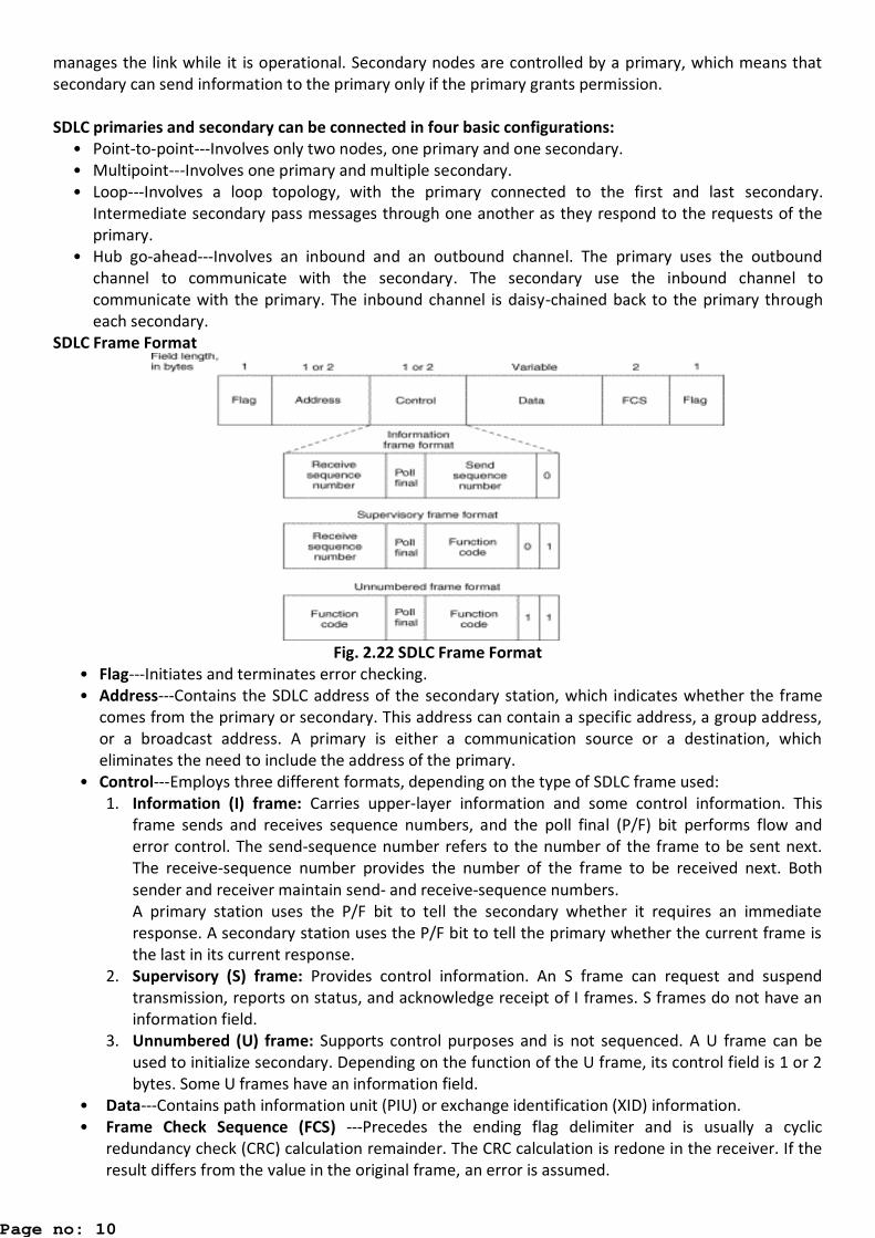
SDLC Frame Format
Fig. 2.22 SDLC Frame Format
• Flag---Initiates and terminates error checking.
• Address---Contains the SDLC address of the secondary station, which indicates whether the frame
comes from the primary or secondary. This address can contain a specific address, a group address,
or a broadcast address. A primary is either a communication source or a destination, which
eliminates the need to include the address of the primary.
• Control---Employs three different formats, depending on the type of SDLC frame used:
1. Information (I) frame: Carries upper-layer information and some control information. This
frame sends and receives sequence numbers, and the poll final (P/F) bit performs flow and
error control. The send-sequence number refers to the number of the frame to be sent next.
The receive-sequence number provides the number of the frame to be received next. Both
sender and receiver maintain send- and receive-sequence numbers.
A primary station uses the P/F bit to tell the secondary whether it requires an immediate
response. A secondary station uses the P/F bit to tell the primary whether the current frame is
the last in its current response.
2. Supervisory (S) frame: Provides control information. An S frame can request and suspend
transmission, reports on status, and acknowledge receipt of I frames. S frames do not have an
information field.
3. Unnumbered (U) frame: Supports control purposes and is not sequenced. A U frame can be
used to initialize secondary. Depending on the function of the U frame, its control field is 1 or 2
bytes. Some U frames have an information field.
• Data---Contains path information unit (PIU) or exchange identification (XID) information.
• Frame Check Sequence (FCS) ---Precedes the ending flag delimiter and is usually a cyclic
redundancy check (CRC) calculation remainder. The CRC calculation is redone in the receiver. If the
result differs from the value in the original frame, an error is assumed.
Page no: 10
HDLC
High-Level Data Link Control (HDLC) is a bit-oriented code-transparent synchronous data link layer
protocol. HDLC provides both connection-oriented and connectionless service. HDLC can be used for point
to multipoint connections, but is now used almost exclusively to connect one device to another, using what
is known as Asynchronous Balanced Mode (ABM). The original master-slave modes Normal Response
Mode (NRM) and Asynchronous Response Mode (ARM) are rarely used.
FRAMING
HDLC frames can be transmitted over synchronous or asynchronous serial communication links. Those links
have no mechanism to mark the beginning or end of a frame, so the beginning and end of each frame has
to be identified. This is done by using a frame delimiter, or flag, which is a unique sequence of bits that is
guaranteed not to be seen inside a frame. This sequence is '01111110', or, in hexadecimal notation, 0x7E.
Each frame begins and ends with a frame delimiter. A frame delimiter at the end of a frame may also mark
the start of the next frame. A sequence of 7 or more consecutive 1-bits within a frame will cause the frame
to be aborted.
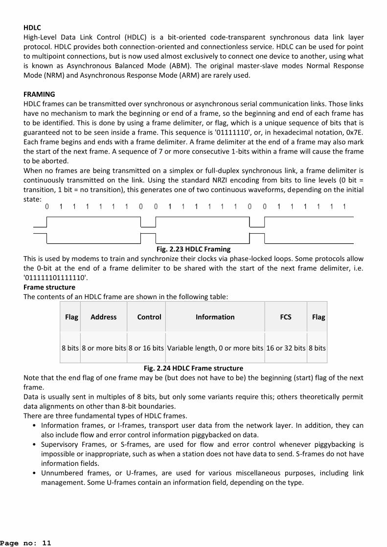
When no frames are being transmitted on a simplex or full-duplex synchronous link, a frame delimiter is
continuously transmitted on the link. Using the standard NRZI encoding from bits to line levels (0 bit =
transition, 1 bit = no transition), this generates one of two continuous waveforms, depending on the initial
state:
Fig. 2.23 HDLC Framing
This is used by modems to train and synchronize their clocks via phase-locked loops. Some protocols allow
the 0-bit at the end of a frame delimiter to be shared with the start of the next frame delimiter, i.e.
'011111101111110'.
Frame structure
The contents of an HDLC frame are shown in the following table:
Flag Address Control Information FCS Flag
8 bits 8 or more bits 8 or 16 bits Variable length, 0 or more bits 16 or 32 bits 8 bits
Fig. 2.24 HDLC Frame structure
Note that the end flag of one frame may be (but does not have to be) the beginning (start) flag of the next
frame.
Data is usually sent in multiples of 8 bits, but only some variants require this; others theoretically permit
data alignments on other than 8-bit boundaries.
There are three fundamental types of HDLC frames.
• Information frames, or I-frames, transport user data from the network layer. In addition, they can
also include flow and error control information piggybacked on data.
• Supervisory Frames, or S-frames, are used for flow and error control whenever piggybacking is
impossible or inappropriate, such as when a station does not have data to send. S-frames do not have
information fields.
• Unnumbered frames, or U-frames, are used for various miscellaneous purposes, including link
management. Some U-frames contain an information field, depending on the type.
Page no: 11
BISYNC
Binary Synchronous Communication (BSC or Bisync) is an IBM character-oriented, half duplex link protocol,
announced in 1967 after the introduction of System/360. It replaced the synchronous transmit-receive
(STR) protocol used with second generation computers. The intent was that common link management
rules could be used with three different character encodings for messages. Six-bit Transcode looked
backwards to older systems.
BISYNC establishes rules for transmitting binary-coded data between a terminal and a host computer's
BISYNC port. While BISYNC is a half-duplex protocol, it will synchronize in both directions on a full-duplex
channel. BISYNC supports both point-to-point (over leased or dial-up lines) and multipoint transmissions.
Each message must be acknowledged, adding to its overhead.
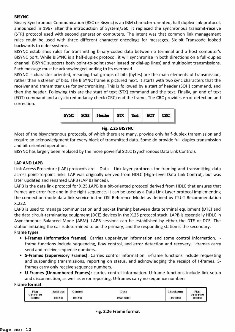
BISYNC is character oriented, meaning that groups of bits (bytes) are the main elements of transmission,
rather than a stream of bits. The BISYNC frame is pictured next. It starts with two sync characters that the
receiver and transmitter use for synchronizing. This is followed by a start of header (SOH) command, and
then the header. Following this are the start of text (STX) command and the text. Finally, an end of text
(EOT) command and a cyclic redundancy check (CRC) end the frame. The CRC provides error detection and
correction.
Fig. 2.25 BISYNC
Most of the bisynchronous protocols, of which there are many, provide only half-duplex transmission and
require an acknowledgment for every block of transmitted data. Some do provide full-duplex transmission
and bit-oriented operation.
BISYNC has largely been replaced by the more powerful SDLC (Synchronous Data Link Control).
LAP AND LAPB
Link Access Procedure (LAP) protocols are Data Link layer protocols for framing and transmitting data
across point-to-point links. LAP was originally derived from HDLC (High-Level Data Link Control), but was
later updated and renamed LAPB (LAP Balanced).
LAPB is the data link protocol for X.25.LAPB is a bit-oriented protocol derived from HDLC that ensures that
frames are error free and in the right sequence. It can be used as a Data Link Layer protocol implementing
the connection-mode data link service in the OSI Reference Model as defined by ITU-T Recommendation
X.222.
LAPB is used to manage communication and packet framing between data terminal equipment (DTE) and
the data circuit-terminating equipment (DCE) devices in the X.25 protocol stack. LAPB is essentially HDLC in
Asynchronous Balanced Mode (ABM). LAPB sessions can be established by either the DTE or DCE. The
station initiating the call is determined to be the primary, and the responding station is the secondary.
Frame types
• I-Frames (Information frames): Carries upper-layer information and some control information. I-
frame functions include sequencing, flow control, and error detection and recovery. I-frames carry
send and receive sequence numbers.
• S-Frames (Supervisory Frames): Carries control information. S-frame functions include requesting
and suspending transmissions, reporting on status, and acknowledging the receipt of I-frames. S-
frames carry only receive sequence numbers.
• U-Frames (Unnumbered Frames): carries control information. U-frame functions include link setup
and disconnection, as well as error reporting. U-frames carry no sequence numbers
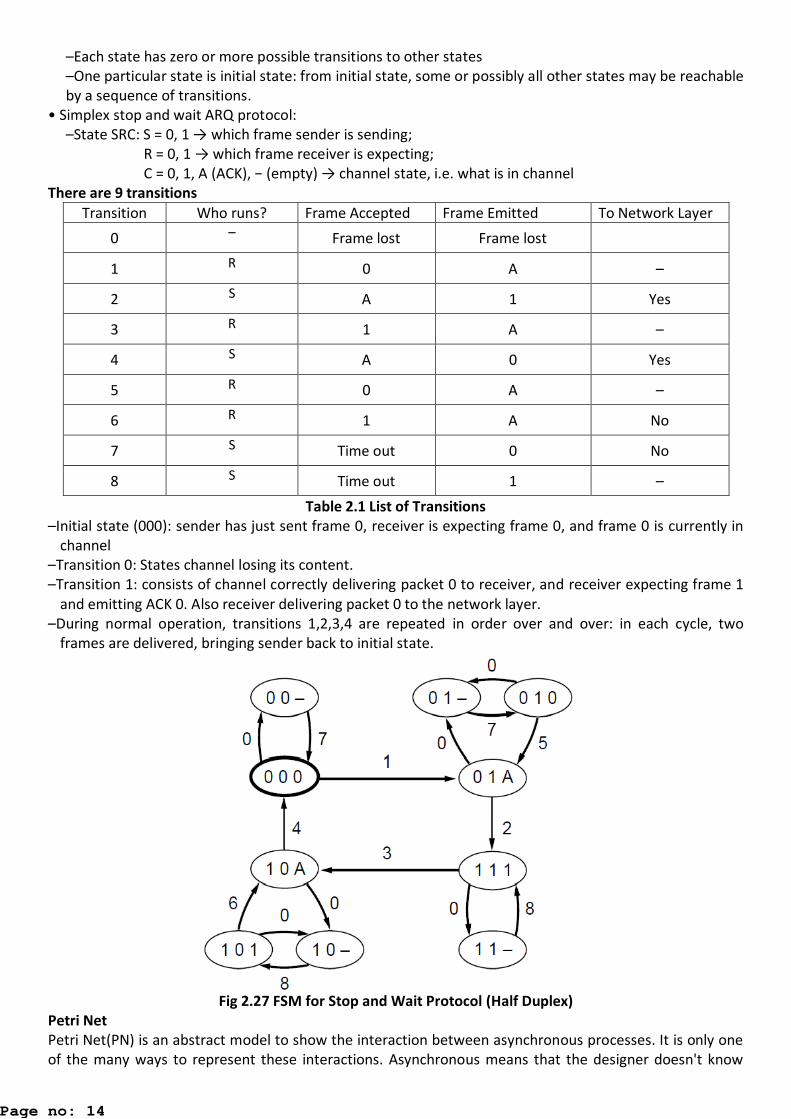
Frame format
Fig. 2.26 Frame format
Page no: 12

Flag – The value of the flag is always 0x7E. In order to ensure that the bit pattern of the frame delimiter
flag does not appear in the data field of the frame (and therefore cause frame misalignment), a
technique known as Bit stuffing is used by both the transmitter and the receiver.
Address field – In LAPB, this field has no meaning since the protocol works in a point to point mode and
the DTE network address is represented in the layer 3 packets. This byte is therefore put to a
different use; it separates the link commands from the responses and can have only two values:
0x01 and 0x03. 01 identifies frames containing commands from DTE to DCE and responses to these
commands from DCE to DTE. 03 are used for frames containing commands from DCE to DTE and for
responses from DTE to DCE.
Control field – it serves to identify the type of the frame. In addition, it includes sequence numbers,
control features and error tracking according to the frame type.
Modes of operation
LAPB works in the Asynchronous Balanced Mode (ABM). This mode is balanced (i.e., no master/slave
relationship) and is signified by the SABM (E)/SM frame. Each station may initialize, supervise, recover
from errors, and send frames at any time. The DTE and DCE are treated as equals.
FCS – The Frame Check Sequence enables a high level of physical error control by allowing the integrity of
the transmitted frame data to be checked.
Window size – LAPB supports an extended window size (modulo 128 and modulo 32768) where the
maximum number of outstanding frames for acknowledgment is raised from 7 (modulo 8) to 127 (modulo
128) and 32767 (modulo 32768).
Protocol operation
LAPB has no master/slave node relationships. The sender uses the Poll bit in command frames to insist on
an immediate response. In the response frame this same bit becomes the receivers Final bit. The receiver
always turns on the Final bit in its response to a command from the sender with the Poll bit set. The P/F bit
is generally used when either end becomes unsure about proper frame sequencing because of a possible
missing acknowledgment, and it is necessary to re-establish a point of reference. It is also used to trigger
an acknowledgment of outstanding I-frames.
Protocol verification:
Finite State Machine Models
A finite-state machine (FSM) or finite-state automaton (plural: automata), or simply a state machine, is a
mathematical model of computation used to design both computer programs and sequential logic circuits.
It is conceived as an abstract machine that can be in one of a finite number of states. The machine is in
only one state at a time; the state it is in at any given time is called the current state. It can change from
one state to another when initiated by a triggering event or condition; this is called a transition. A
particular FSM is defined by a list of its states, and the triggering condition for each transition.
Finite-state machines can model a large number of problems, among which are electronic design
automation, communication protocol design, language parsing and other engineering applications. In
biology and artificial intelligence research, state machines or hierarchies of state machines have been used
to describe neurological systems. In linguistics, they are used to describe simple parts of the grammars of
natural languages.
The FSM Consist of
States are those instants that the protocol machine is waiting for, the next event to happen e.g.
waiting for ACK.
Transitions occur when some event happens. E.g. when a frame is sent, when a frame is arriving,
when timer goes off, when an interrupt occurs.
Initial State gives description of the system i.e. when it starts running.
A deadlock is a situation in which the protocol can make no more forward progress, there exists a
set of states from which there is no exit and no progress can be made.
How to know a protocol really works → specifies and verify protocol using, e.g. finite state machine
–Each protocol machine (sender or receiver) is at a specific state at every time instant
Page no: 13
–Each state has zero or more possible transitions to other states
–One particular state is initial state: from initial state, some or possibly all other states may be reachable
by a sequence of transitions.
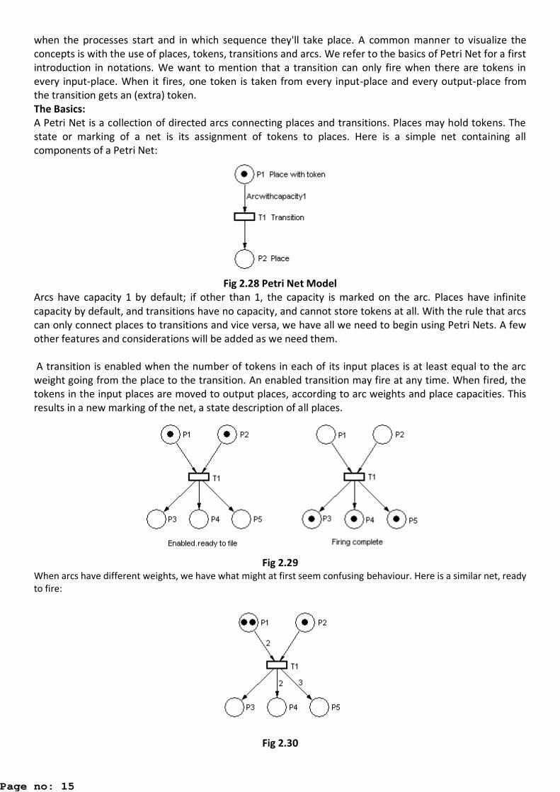
• Simplex stop and wait ARQ protocol:
–State SRC: S = 0, 1 → which frame sender is sending;
R = , → which frame receiver is expecting;
C = 0, 1, A (ACK), − (e pt ) → channel state, i.e. what is in channel
There are 9 transitions
Transition Who runs? Frame Accepted Frame Emitted To Network Layer
0 – Frame lost Frame lost
1 R 0 A –
2 S A 1 Yes
3 R 1 A –
4 S A 0 Yes
5 R 0 A –
6 R 1 A No
7 S Time out 0 No
8 S Time out 1 –
Table 2.1 List of Transitions
–Initial state (000): sender has just sent frame 0, receiver is expecting frame 0, and frame 0 is currently in
channel
–Transition 0: States channel losing its content.
–Transition 1: consists of channel correctly delivering packet 0 to receiver, and receiver expecting frame 1
and emitting ACK 0. Also receiver delivering packet 0 to the network layer.
–During normal operation, transitions 1,2,3,4 are repeated in order over and over: in each cycle, two
frames are delivered, bringing sender back to initial state.
Fig 2.27 FSM for Stop and Wait Protocol (Half Duplex)
Petri Net
Petri Net(PN) is an abstract model to show the interaction between asynchronous processes. It is only one
of the many ways to represent these interactions. Asynchronous means that the designer doesn't know
Page no: 14
when the processes start and in which sequence they'll take place. A common manner to visualize the
concepts is with the use of places, tokens, transitions and arcs. We refer to the basics of Petri Net for a first
introduction in notations. We want to mention that a transition can only fire when there are tokens in
every input-place. When it fires, one token is taken from every input-place and every output-place from
the transition gets an (extra) token.
The Basics:
A Petri Net is a collection of directed arcs connecting places and transitions. Places may hold tokens. The
state or marking of a net is its assignment of tokens to places. Here is a simple net containing all
components of a Petri Net:
Fig 2.28 Petri Net Model
Arcs have capacity 1 by default; if other than 1, the capacity is marked on the arc. Places have infinite
capacity by default, and transitions have no capacity, and cannot store tokens at all. With the rule that arcs
can only connect places to transitions and vice versa, we have all we need to begin using Petri Nets. A few
other features and considerations will be added as we need them.
A transition is enabled when the number of tokens in each of its input places is at least equal to the arc
weight going from the place to the transition. An enabled transition may fire at any time. When fired, the
tokens in the input places are moved to output places, according to arc weights and place capacities. This
results in a new marking of the net, a state description of all places.
Fig 2.29
When arcs have different weights, we have what might at first seem confusing behaviour. Here is a similar net, ready
to fire:
Fig 2.30
Page no: 15
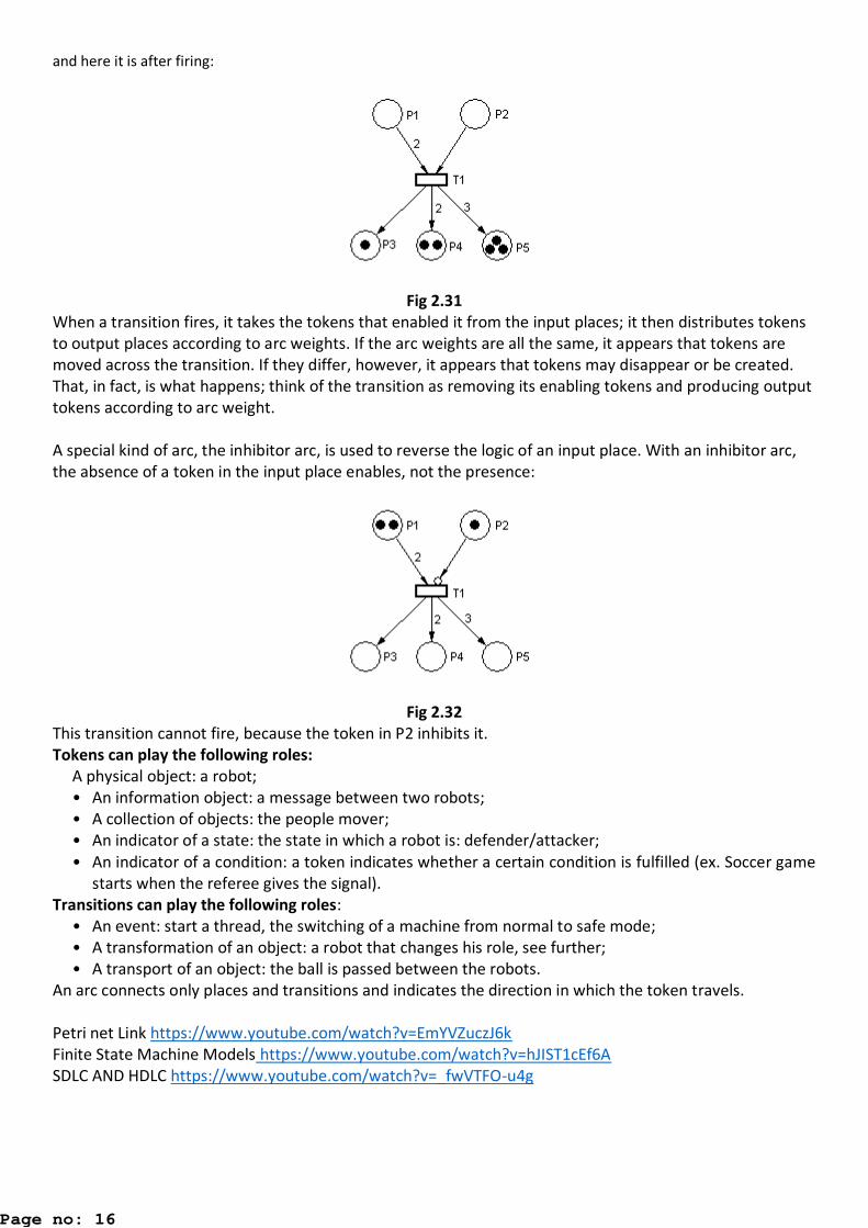
and here it is after firing:
Fig 2.31
When a transition fires, it takes the tokens that enabled it from the input places; it then distributes tokens
to output places according to arc weights. If the arc weights are all the same, it appears that tokens are
moved across the transition. If they differ, however, it appears that tokens may disappear or be created.
That, in fact, is what happens; think of the transition as removing its enabling tokens and producing output
tokens according to arc weight.
A special kind of arc, the inhibitor arc, is used to reverse the logic of an input place. With an inhibitor arc,
the absence of a token in the input place enables, not the presence:
Fig 2.32
This transition cannot fire, because the token in P2 inhibits it.
Tokens can play the following roles:
A physical object: a robot;
• An information object: a message between two robots;
• A collection of objects: the people mover;
• An indicator of a state: the state in which a robot is: defender/attacker;
• An indicator of a condition: a token indicates whether a certain condition is fulfilled (ex. Soccer game
starts when the referee gives the signal).
Transitions can play the following roles:
• An event: start a thread, the switching of a machine from normal to safe mode;
• A transformation of an object: a robot that changes his role, see further;
• A transport of an object: the ball is passed between the robots.
An arc connects only places and transitions and indicates the direction in which the token travels.
Petri net Link https://www.youtube.com/watch?v=EmYVZuczJ6k
Finite State Machine Models https://www.youtube.com/watch?v=hJIST1cEf6A
SDLC AND HDLC https://www.youtube.com/watch?v=_fwVTFO-u4g
Page no: 16