Embed Size (px)
Citation preview

DEPARTMENT OF ELETRONICS AND COMMUNICATION ENGINEERING
COURSE NOTES
SUBJECT: DIGITAL ELECTRONICS SUBJECT CODE: EC2203
FACULTY NAME/DESIGNATION: SUGAPRIYAA.THA / LECTURER
CLASS: II YEAR ECE
UNIT-I
MINIMISATION TECHNIQUES AND LOGIC GATES
Minimization Techniques: Boolean postulates and laws – De-Morgan’s Theorem - Principle of
Duality - Boolean expression - Minimization of Boolean expressions –– Minterm – Maxterm -
Sum of Products (SOP) – Product of Sums (POS) – Karnaugh map Minimization – Don’t care
conditions - Quine-McCluskey method of minimization.
Logic Gates:AND, OR, NOT, NAND, NOR, Exclusive–OR and Exclusive–NORImplementations
of Logic Functions using gates, NAND–NOR implementations – Multi level gate
implementations- Multi output gate implementations. TTL and CMOS Logic and their
characteristics – Tristate gates.
OBJECTIVE
� To learn what is meant by digital and how it differs from analog
� To know basics of Boolean algebra along with boolean laws and theorems
� Methods to minimize Boolean expressions
� To learn logic gates and their implementations
� To know digital logic families

INTRODUCTION
DIGITAL ELECTRONICS
� Analog electronics are electronic systems with a continuously variable signal, in contrast
to digital electronics where signals usually take only two different levels.
� They are represented by two voltage bands:
One near a reference value �termed as "ground" or zero voltsor "false" ("0")
Another value near the supply voltage� "true" ("1")
� Digital techniques are useful because it is easier to get an electronic device to switch into
one of a number of known states than to accurately reproduce a continuous range of values.
� Digital electronic circuits are usually made from large assemblies of logic gates, simple
electronic representations of Boolean logic functions.
ADVANTAGES
� Easier to design.
� Information storage is easy.
� Accuracy and precision are greater.
� Operations can be programmed. Analog systems can also be programmed, but the available
operations variety and complexity is severely limited.
� Digital circuits are less affected by noise.
� More digital circuitry can be fabricated on IC chips.
LIMITATIONS
1. Most physical quantities in real world are analog in nature, and these quantities are often
the inputs and outputs that are being monitored, operated on, and controlled by a system.
2. Thus conversion to digital format and re-conversion to analog format is needed.
The major difference between analog and digital quantities can be stated simply as follows:
� Analog = continuous
� Digital = discrete (step by step)
ANALOG ISSUES IN DIGITAL CIRCUITS
� Digital circuits are made from analog components. The design must assure that the analog
nature of the components doesn't dominate the desired digital behavior.
� Digital systems must manage noise and timing margins, parasitic inductances and
capacitances, and filter power connections.

ANALOG AND DIGITAL TECHNOLOGY
In analog technology, a wave is recorded or used in its original form.
For example, in an analog tape recorder, a signal is taken straight from the microphone and laid
onto tape. The wave from the microphone is an analog wave, and therefore the wave on the tape is
analog as well. That wave on the tape can be read, amplified and sent to a speaker to produce the
sound.
In digital technology, the analog wave is sampled at some interval, and then turned into numbers
that are stored in the digital device.
On a CD, the sampling rate is 44,000 samples per second. So on a CD, there are 44,000 numbers
stored per second of music. To hear the music, the numbers are turned into a voltage wave that
approximates the original wave.
BOOLEAN ALGEBRA
The basic mathematics needed for the study of the logic design of digital systems is “Boolean
Algebra”
Switching Algebra – Boolean algebra in which all of the variables assumes only one of two
values (i.e ‘0’ and ‘1’)
The usual purpose of doing Boolean algebra is to simplify the design of a digital circuit that
performs a function, either to minimize the number of gates, or to minimize the time for the value
of the function to settle down after a change in its input(s), or some other practical criterion.
BASIC OPERATIONS
The basic operations of boolean algebra are
� AND
� OR
� Complement (or inverse)
The complement of ‘0‘ is ‘1’ and the complement of ‘1’ is ‘0’
0′ = 1
1′ = 0
(′) � complementation

BOOLEAN POSTULATES AND LAWS
Assume A, B, and C are logical states that can have the values 0 (false) and 1 (true).
"+" means OR, "·" means AND, and NOT
[A] means NOT A.
Postulates
(1) A + 0 = A A · 1 = A identity
(2) A + NOT
[A] = 1 A · NOT
[A] = 0 complement
(3) A + B = B + A A · B = B · A commutative law
(4) A + (B + C) = (A + B) + C A · (B · C) = (A · B) · C associative law
(5) A + (B · C) = (A + B) · (A + C) A · (B + C) = (A · B) + (A · C) distributive law
Theorems
(6) A + A = A A · A = A
(7) A + 1 = 1 A · 0 = 0
(8) A + (A · B) = A A · ( A + B) = A
(9) A + (NOT
[A] · B) = A + B A · (NOT
[A] + B) = A · B
(10) (A · B) + (
NOT[A] · C) + (B · C) = (A · B) +
(NOT
[A] · C)
A · (B + C) = (A · B) +
(A · C)
(11) NOT
[A + B] = NOT
[A] · NOT
[B]
NOT[A · B] =
NOT[A] +
NOT[B]
de Morgan's
theorem
DE-MORGAN’S THEOREM
De Morgan's laws are rules relating the logical operators "and" and "or" in terms of each other via
negation. With two operands A and B:
In another form:
NOT (P AND Q) = (NOT P) OR (NOT Q)
NOT (P OR Q) = (NOT P) AND (NOT Q)

The rules can be expressed in English as:
"The negation of a conjunction is the disjunction of the negations" and
"The negation of a disjunction is the conjunction of the negations"
DEMORGAN'S THEOREM IN GATES
Two forms of DeMorgan's Theorem implemented with basic gates.
PRINCIPLE OF DUALITY
According to principle of duality" Dual of one expression is obtained by replacing AND (.) with
OR(+) and OR with AND together with replacement of 1 with 0 and 0 with 1.
Eg: consider the expression A+B=0. The dual of this expression is obtained by replacing ‘+’with’
.’ and ‘0’ by ‘1’.
e.g. A.B=1 is dual of A+B=0
BOOLEAN EXPRESSION
� A Boolean expression is an expression in a programming language that produces a Boolean
value when evaluated, i.e. one of true or false.
� A Boolean expression may be composed of a combination of the Boolean constants true or
false, Boolean-typed variables, Boolean-valued operators, and Boolean-valued functions.
Example
• The value for (5 > 3) is evaluated as true

MINIMIZATION OF BOOLEAN EXPRESSIONS
1. Simplify: C + BC
Expression Rule(s) Used
C + BC Original Expression
C + (B + C) DeMorgan's Law.
(C + C) + B Commutative, Associative Laws.
T + B Complement Law.
T Identity Law.
2. Simplify: AB(A + B)(B + B)
Expression Rule(s) Used
AB(A + B)(B + B) Original Expression
AB(A + B) Complement law, Identity law.
(A + B)(A + B) DeMorgan's Law
A + BB
Distributive law. This step uses the fact that or distributes over
and. It can look a bit strange since addition does not distribute
over multiplication.
A Complement, Identity.

3. Simplify: (A + C)(AD + AD) + AC + C
Expression Rule(s) Used
(A + C)(AD + AD) + AC + C Original Expression
(A + C)A(D + D) + AC + C Distributive.
(A + C)A + AC + C Complement, Identity.
A((A + C) + C) + C Commutative, Distributive.
A(A + C) + C Associative, Idempotent.
AA + AC + C Distributive.
A + (A + T)C Idempotent, Identity, Distributive.
A + C Identity, twice.

4. Simplify: A(A + B) + (B + AA)(A + B)
Expression Rule(s) Used
A(A + B) + (B + AA)(A + B) Original Expression
AA + AB + (B + A)A + (B + A)B Idempotent (AA to A), then Distributive, used
twice.
AB + (B + A)A + (B + A)B
Complement, then Identity. (Strictly speaking, we
also used the Commutative Law for each of these
applications.)
AB + BA + AA + BB + AB Distributive, two places.
AB + BA + A + AB Idempotent (for the A's), then Complement and
Identity to remove BB.
AB + AB + AT + AB Commutative, Identity; setting up for the next
step.
AB + A(B + T + B) Distributive.
AB + A Identity, twice (depending how you count it).
A + AB Commutative.
(A + A)(A + B) Distributive.
A + B Complement, Identity.

CANONICAL FORMS
� In Boolean algebra, any Boolean function can be expressed in a canonical form using the
dual concepts of minterms and maxterms
� Minterms are called products because they are the logical AND of a set of variables
� Maxterms are called sums because they are the logical OR of a set of variables
MINTERMS
A binary variable may appear either in its normal form (x) or in its complement form (x′). Consider
two binary variables x and y combined with an AND operation. There are four possible
combinations,
xy, x′y, xy′, x′y′
Each of these four AND terms is called a minterm or a standard product term. Similarly if there are
n variables, that can be combined to form 2n
minterms.
Examples:
The minterms for two variables are A'B', AB', A'B, and AB.
The minterms for three variables A, B, and C areA'B'C', AB'C', A'BC', ABC', A'B'C, AB'C, A'BC,
and ABC.
In general, there are 2nminterms for n variables.
Binary
Equivalent
(ABC)
Minterm Symbol
000 A'B'C' m0
001 A'B'C m1
010 A'BC' m2
011 A'BC m3
100 AB'C' m4
101 AB'C m5
110 ABC' m6
111 ABC m7

MAXTERM:
� A maxterm is a logical expression of n variables that employs only the complement
operator and the disjunction operator.
Eg. The maxterms for two variables are A'+B', A+B', A'+B, and A+B.
Eg. The maxterms for three variables A, B, and C areA'+B'+C', A+B'+C', A'+B+C', A+B+C',
A'+B'+C, A+B'+C, A'+B+C, and A+B+C.
In general, there are 2nmaxterms for n variables.
Binary
Equivalent
(ABC)
Maxterm Symbol
000 A+B+C M0
001 A+B+C' M1
010 A+B'+C M2
011 A+B'+C' M3
100 A'+B+C M4
101 A'+B+C' M5
110 A'+B’+C M6
111 A'+B'+C' M7
SOP AND POS
� The dual canonical forms of any Boolean function are a "sum of minterms" and a "product
of maxterms."
� The term "Sum of Products" or "SoP" is widely used for the canonical form that is a
disjunction (OR) of minterms. Its De Morgan dual is a "Product of Sums" or "PoS" for the
canonical form that is a conjunction (AND) of maxterms.

� These forms allow for greater analysis into the simplification of these functions, which is of
great importance in the minimization or other optimization of digital circuits.
SIMPLIFICATION OF BOOLEAN EXPRESSIONS
Simplification of Boolean functions is mainly used to reduce the gate count of a design.
Advantages
Less number of gates means less power consumption, sometimes the circuit works faster and also
when number of gates is reduced, cost also comes down.
There are many ways to simplify a logic design, some of them are given below.
• Algebraic Simplification.
o Simplify symbolically using theorems/postulates.
o Requires good skills
• Karnaugh Maps.
o Diagrammatic technique using 'Venn-like diagram'.
o Limited to no more than 6 variables.
KARNAUGH MAP
• The Karnaugh map (K-map), is a method to simplify Boolean algebra expressions.
• In a Karnaugh map the boolean variables are transferred (generally from a truth table) and
ordered according to the principles of Gray code in which only one variable changes in
between adjacent squares.
• Karnaugh maps provide a systematic method to obtain simplified sum-of-products (SOPs)
Boolean expressions.
• This is a compact way of representing a truth table and is a technique that is used to
simplify logic expressions. It is ideally suited for four or less variables, becoming
cumbersome for five or more variables.
• Each square represents either a minterm or maxterm. A K-map of n variables will have
2squares. For a Boolean expression, product terms are denoted by 1's, while sum terms are
denoted by 0's - but 0's are often left blank.
• A K-map consists of a grid of squares, each square representing one canonical minterm
combination of the variables or their inverse. The map is arranged so that squares
representing minterms which differ by only one variable are adjacent both vertically and
horizontally. Therefore XY'Z' would be adjacent to X'Y'Z' and would also adjacent to XY'Z
and XYZ'.

MINIMIZATION TECHNIQUE
• Based on the Unifying Theorem: X + X' = 1
• The expression to be minimized should generally be in sum-of-product form (If necessary,
the conversion process is applied to create the sum-of-product form).
• The function is mapped onto the K-map by marking a 1 in those squares corresponding to
the terms in the expression to be simplified (The other squares may be filled with 0's).
• Pairs of 1's on the map which are adjacent are combined using the theorem Y(X+X') = Y
where Y is any Boolean expression (If two pairs are also adjacent, then these can also be
combined using the same theorem).
• The minimization procedure consists of recognizing those pairs and multiple pairs.
o These are circled indicating reduced terms.
o Groups which can be circled are those which have two (21) 1's, four (2
2) 1's, eight
(23) 1's, and so on.
o Note that because squares on one edge of the map are considered adjacent to those
on the opposite edge, group can be formed with these squares.
o Groups are allowed to overlap.
• The objective is to cover all the 1's on the map in the fewest number of groups and to create
the largest groups to do this.
• Once all possible groups have been formed, the corresponding terms are identified.
o A group of two 1's eliminates one variable from the original minterm.
o A group of four 1's eliminates two variables from the original minterm.
o A group of eight 1's eliminates three variables from the original minterm, and so on.
o The variables eliminated are those which are different in the original minterms of
the group.
2-Variable K-Map
In any K-Map, each square represents a minterm. Adjacent squares always differ by just one literal
(So that the unifying theorem may apply: X + X' = 1). For the 2-variable case (e.g.: variables X,
Y), the map can be drawn as below. Two variable map is the one which has got only two variables
as input.
Equivalent labeling
K-map needs not follow the ordering as shown in the figure above. What this means is that we can
change the position of m0, m1, m2, m3 of the above figure as shown in the two figures below.

Position assignment is the same as the default k-maps positions. This is the one which we will be
using throughout this tutorial.
This figure is with changed position of m0, m1, m2, m3.
The K-map for a function is specified by putting a '1' in the square corresponding to a minterm, a '0'
otherwise.
Example- Carry and Sum of a half adder
In this example we have the truth table as input, and we have two output functions. Generally we
may have n output functions for m input variables. Since we have two output functions, we need to
draw two k-maps (i.e. one for each function). Truth table of 1 bit adder is shown below. Draw the
k-map for Carry and Sum as shown below.
X Y Sum Carry
0 0 0 0
0 1 1 0
1 0 1 0
1 1 0 1

Grouping/Circling K-maps
The power of K-maps is in minimizing the terms, K-maps can be minimized with the help of
grouping the terms to form single terms. When forming groups of squares, observe/consider the
following:
• Every square containing 1 must be considered at least once.
• A square containing 1 can be included in as many groups as desired.
• A group must be as large as possible.
• If a square containing 1 cannot be placed in a group, then leave it out to include in final
expression.
• The number of squares in a group must be equal to 2
• , i.e. 2,4,8,.
• The map is considered to be folded or spherical, therefore squares at the end of a row or
column are treated as adjacent squares.
• The simplified logic expression obtained from a K-map is not always unique. Groupings
can be made in different ways.
• Before drawing a K-map the logic expression must be in canonical form.

In the next few pages we will see some examples on grouping.
Example of invalid groups

Example - X'Y+XY
In this example we have the equation as input, and we have one output function. Draw the k-map
for function F with marking 1 for X'Y and XY position. Now combine two 1's as shown in figure
to form the single term. As you can see X and X' get canceled and only Y remains.
F = Y
Example - X'Y+XY+XY'
In this example we have the equation as input, and we have one output function. Draw the k-map
for function F with marking 1 for X'Y, XY and XY position. Now combine two 1's as shown in
figure to form the two single terms.
F = X + Y

3-Variable K-Map
There are 8 minterms for 3 variables (X, Y, Z). Therefore, there are 8 cells in a 3-variable K-map.
One important thing to note is that K-maps follow the gray code sequence, not the binary one.
Using gray code arrangement ensures that minterms of adjacent cells differ by only ONE literal.
(Other arrangements which satisfy this criterion may also be used.)
Each cell in a 3-variable K-map has 3 adjacent neighbours. In general, each cell in an n-variable K-
map has n adjacent neighbours.
There is wrap-around in the K-map
• X'Y'Z' (m0) is adjacent to X'YZ' (m2)
• XY'Z' (m4) is adjacent to XYZ' (m6)

Example
F = XYZ'+XYZ+X'YZ
F = XY + YZ
Example
F(X,Y,Z) = (1,3,4,5,6,7)
F = X + Z
4-Variable K-Map
There are 16 cells in a 4-variable (W, X, Y, Z); K-map as shown in the figure below.

There are 2 wrap-around: a horizontal wrap-around and a vertical wrap-around. Every cell thus has
4 neighbours. For example, the cell corresponding to minterm m0 has neighbours m1, m2, m4 and
m8.
Example
F(W,X,Y,Z) = (1,5,12,13)

F = WY'Z + W'Y'Z
Example
F(W,X,Y,Z) = (4, 5, 10, 11, 14, 15)
F = W'XY' + WY
5-Variable K-Map
There are 32 cells in a 5-variable (V, W, X, Y, Z); K-map as shown in the figure below.

Inverse Function
• The 0's on a K-map indicate when the function is 0.
• We can minimize the inverse function by grouping the 0's (and any suitable don't cares)
instead of the 1's.
• This technique leads to an expression which is not logically equivalent to that obtained by
grouping the 1's (i.e., the inverse of X != X').
• Minimizing for the inverse function may be particularly advantageous if there are many
more 0's than 1's on the map.
• We can also apply De Morgan's theorem to obtain a product-of-sum expression.
QUINE-McCLUSKEY MINIMIZATION
• Quine-McCluskey minimization method uses the same theorem to produce the solution as
the K-map method, namely X(Y+Y')=X
Minimization Technique
• The expression is represented in the canonical SOP form if not already in that form.
• The function is converted into numeric notation.
• The numbers are converted into binary form.
• The minterms are arranged in a column divided into groups.
• Begin with the minimization procedure.
o Each minterm of one group is compared with each minterm in the group
immediately below.
o Each time a number is found in one group which is the same as a number in the
group below except for one digit, the numbers pair is ticked and a new composite is
created.

o This composite number has the same number of digits as the numbers in the pair
except the digit different which is replaced by an "x".
• The above procedure is repeated on the second column to generate a third column.
• The next step is to identify the essential prime implicants, which can be done using a prime
implicant chart.
o Where a prime implicant covers a minterm, the intersection of the corresponding
row and column is marked with a cross.
o Those columns with only one cross identify the essential prime implicants. -> These
prime implicants must be in the final answer.
o The single crosses on a column are circled and all the crosses on the same row are
also circled, indicating that these crosses are covered by the prime implicants
selected.
o Once one cross on a column is circled, all the crosses on that column can be circled
since the minterm is now covered.
o If any non-essential prime implicant has all its crosses circled, the prime implicant
is redundant and need not be considered further.
• Next, a selection must be made from the remaining nonessential prime implicants, by
considering how the non-circled crosses can be covered best.
o One generally would take those prime implicants which cover the greatest number
of crosses on their row.
o If all the crosses in one row also occur on another row which includes further
crosses, then the latter is said to dominate the former and can be selected.
o The dominated prime implicant can then be deleted.
Example
Find the minimal sum of products for the Boolean expression, f= (1,2,3,7,8,9,10,11,14,15),
using Quine-McCluskey method.
• Firstly these minterms are represented in the binary form as shown in the table below. The
above binary representations are grouped into a number of sections in terms of the number
of 1's as shown in the table below.
• Binary representation of minterms
Minterms U V W X
1 0 0 0 1
2 0 0 1 0
3 0 0 1 1
7 0 1 1 1
8 1 0 0 0
9 1 0 0 1
10 1 0 1 0

11 1 0 1 1
14 1 1 1 0
15 1 1 1 1
• Group of minterms for different number of 1's
No of 1's Minterms U V W X
1 1 0 0 0 1
1 2 0 0 1 0
1 8 1 0 0 0
2 3 0 0 1 1
2 9 1 0 0 1
2 10 1 0 1 0
3 7 0 1 1 1
3 11 1 0 1 1
3 14 1 1 1 0
4 15 1 1 1 1
• Any two numbers in these groups which differ from each other by only one variable can be
chosen and combined, to get 2-cell combination, as shown in the table below.
2-Cell combinations
Combinations U V W X
(1,3) 0 0 - 1
(1,9) - 0 0 1
(2,3) 0 0 1 -
(2,10) - 0 1 0
(8,9) 1 0 0 -
(8,10) 1 0 - 0
(3,7) 0 - 1 1
(3,11) - 0 1 1
(9,11) 1 0 - 1
(10,11) 1 0 1 -
(10,14) 1 - 1 0
(7,15) - 1 1 1
(11,15) 1 - 1 1

(14,15) 1 1 1 -
• From the 2-cell combinations, one variable and dash in the same position can be combined
to form 4-cell combinations as shown in the figure below.
4-Cell combinations
Combinations U V W X
(1,3,9,11) - 0 - 1
(2,3,10,11) - 0 1 -
(8,9,10,11) 1 0 - -
(3,7,11,15) - - 1 1
(10,11,14,15) 1 - 1 -
• The cells (1,3) and (9,11) form the same 4-cell combination as the cells (1,9) and (3,11).
The order in which the cells are placed in a combination does not have any effect. Thus the
(1,3,9,11) combination could be written as (1,9,3,11).
• From above 4-cell combination table, the prime implicants table can be plotted as shown in
table below.
Prime Implicants Table
Prime
Implicants 1 2 3 7 8 9 10 11 14 15
(1,3,9,11) X - X - - X - X - -
(2,3,10,11) - X X - - - X X - -
(8,9,10,11) - - - - X X X X - -
(3,7,11,15) - - - - - - X X X X
- X X - X X - - - X -
• The columns having only one cross mark correspond to essential prime implicants. A
yellow cross is used against every essential prime implicant. The prime implicants sum
gives the function in its minimal SOP form.
• Y = V'X + V'W + UV' + WX + UW

LOGIC GATES
� A logic gate is an electronic circuit/device which makes the logical decisions.
� To arrive at this decisions, the most common logic gates used are OR, AND, NOT, NAND,
and NOR gates.
� The NAND and NOR gates are called universal gates.
� The exclusive-OR gate is another logic gate which can be constructed using AND, OR and
NOT gate.
� Logic gates have one or more inputs and only one output.
� The output is active only for certain input combinations.
� Logic gates are the building blocks of any digital circuit.
� Logic gates are also called switches. With the advent of integrated circuits, switches have
been replaced by TTL (Transistor Transistor Logic) circuits and CMOS circuits.
INVERSION
A small circle on an input or an output indicates inversion.
MULTIPLE INPUT GATES
Given commutative and associative laws, many logic gates can be implemented with more than
two inputs, and for reasons of space in circuits, usually multiple input, complex gates are made.
GATES TYPES
• AND
• OR
• NOT
• BUF
• NAND
• NOR
• XOR
• XNOR

AND Gate
• The AND gate performs logical multiplication, commonly known as AND function. The
AND gate has two or more inputs and single output. The output of AND gate is HIGH only
when all its inputs are HIGH (i.e. even if one input is LOW, Output will be LOW).
• If X and Y are two inputs, then output F can be represented mathematically as F = X.Y,
Here dot (.) denotes the AND operation. Truth table and symbol of the AND gate is shown
in the figure below.
Symbol
Truth Table
X Y F=(X.Y)
0 0 0
0 1 0
1 0 0
1 1 1
• Two input AND gate using "diode-resistor" logic is shown in figure below, where X, Y are
inputs and F is the output.
Circuit

• If X = 0 and Y = 0, then both diodes D1 and D2 are forward biased and thus both diodes
conduct and pull F low.
• If X = 0 and Y = 1, D2 is reverse biased, thus does not conduct. But D1 is forward biased,
thus conducts and thus pulls F low.
• If X = 1 and Y = 0, D1 is reverse biased, thus does not conduct. But D2 is forward biased,
thus conducts and thus pulls F low.
• If X = 1 and Y = 1, then both diodes D1 and D2 are reverse biased and thus both the diodes
are in cut-off and thus there is no drop in voltage at F. Thus F is HIGH.
Switch Representation of AND Gate
• In the figure below, X and Y are two switches which have been connected in series (or just
cascaded) with the load LED and source battery. When both switches are closed, current
flows to LED.
Three Input AND gate
• Since we have already seen how a AND gate works and I will just list the truth table of a 3
input AND gate. The figure below shows its symbol and truth table.
CIRCUIT

TRUTH TABLE
X Y Z F=X.Y.Z
0 0 0 0
0 0 1 0
0 1 0 0
0 1 1 0
1 0 0 0
1 0 1 0
1 1 0 0
1 1 1 1
OR Gate
• The OR gate performs logical addition, commonly known as OR function. The OR gate has
two or more inputs and single output. The output of OR gate is HIGH only when any one
of its inputs are HIGH (i.e. even if one input is HIGH, Output will be HIGH).
• If X and Y are two inputs, then output F can be represented mathematically as F = X+Y.
Here plus sign (+) denotes the OR operation. Truth table and symbol of the OR gate is
shown in the figure below.
SYMBOL

TRUTH TABLE
X Y F=(X+Y)
0 0 0
0 1 1
1 0 1
1 1 1
• Two input OR gate using "diode-resistor" logic is shown in figure below, where X, Y are
inputs and F is the output.
Circuit
• If X = 0 and Y = 0, then both diodes D1 and D2 are reverse biased and thus both the diodes
are in cut-off and thus F is low.
• If X = 0 and Y = 1, D1 is reverse biased, thus does not conduct. But D2 is forward biased,
thus conducts and thus pulling F to HIGH.
• If X = 1 and Y = 0, D2 is reverse biased, thus does not conduct. But D1 is forward biased,
thus conducts and thus pulling F to HIGH.
• If X = 1 and Y = 1, then both diodes D1 and D2 are forward biased and thus both the
diodes conduct and thus F is HIGH.
Switch Representation of OR Gate
• In the figure, X and Y are two switches which have been connected in parallel, and this is
connected in series with the load LED and source battery. When both switches are open,
current does not flow to LED, but when any switch is closed then current flows.

Three Input OR gate
• Since we have already seen how an OR gate works, I will just list the truth table of a 3-
input OR gate. The figure below shows its circuit and truth table.
Truth Table
X Y Z F=X+Y+Z
0 0 0 0
0 0 1 1
0 1 0 1
0 1 1 1
1 0 0 1
1 0 1 1
1 1 0 1
1 1 1 1
NOT Gate
� The NOT gate performs the basic logical function called inversion or complementation.
� NOT gate is also called inverter.
� The purpose of this gate is to convert one logic level into the opposite logic level.
� It has one input and one output. When a HIGH level is applied to an inverter, a LOW level
appears on its output and vice versa.

Symbol
Truth Table
X Y=X'
0 1
1 0
NOT gate using "transistor-resistor" logic is shown in the figure below, where X is the input and F
is the output.
Circuit

When X = 1, The transistor input pin 1 is HIGH, this produces the forward bias across the emitter
base junction and so the transistor conducts. As the collector current flows, the voltage drop across
RL increases and hence F is LOW.
When X = 0, the transistor input pin 2 is LOW: this produces no bias voltage across the
transistor base emitter junction. Thus Voltage at F is HIGH.
BUF Gate
� Buffer or BUF is also a gate with the exception that it does not perform any logical
operation on its input.
� Buffers just pass input to output. Buffers are used to increase the drive strength or
sometime just to introduce delay.
� If X is the input, then output F can be represented mathematically as F = X. Truth table and
symbol of the Buffer gate is shown in the figure below.
Symbol
Truth Table
X Y=X
0 0
1 1
NAND Gate
NAND gate is a cascade of AND gate and NOT gate, as shown in the figure below. It has two or
more inputs and only one output. The output of NAND gate is HIGH when any one of its input is
LOW (i.e. even if one input is LOW, Output will be HIGH).
NAND From AND and NOT

If X and Y are two inputs, then output F can be represented mathematically as F = (X.Y)', Here dot
(.) denotes the AND operation and (') denotes inversion. Truth table and symbol of the N AND
gate is shown in the figure below.
Symbol
Truth Table
X Y F=(X.Y)'
0 0 1
0 1 1
1 0 1
1 1 0
NOR Gate
� NOR gate is a cascade of OR gate and NOT gate, as shown in the figure below.
� It has two or more inputs and only one output. The output of NOR gate is HIGH when any
all its inputs are LOW (i.e. even if one input is HIGH, output will be LOW).
Symbol

� If X and Y are two inputs, then output F can be represented mathematically as F = (X+Y)';
here plus (+) denotes the OR operation and (') denotes inversion.
Truth table and symbol of the NOR gate is shown in the figure below.
Truth Table
X Y F=(X+Y)'
0 0 1
0 1 0
1 0 0
1 1 0
XOR Gate
� An Exclusive-OR (XOR) gate is gate with two or three or more inputs and one output.
� The output of a two-input XOR gate assumes a HIGH state if one and only one input
assumes a HIGH state.
� This is equivalent to saying that the output is HIGH if either input X or input Y is HIGH
exclusively, and LOW when both are 1 or 0 simultaneously.
� If X and Y are two inputs, then output F can be represented mathematically as F = X Y,
Here denotes the XOR operation.
� X Y and is equivalent to X.Y' + X'.Y. Truth table and symbol of the XOR gate is shown
in the figure below.
XOR From Simple gates

Symbol
Truth Table
X Y F=(X Y)
0 0 0
0 1 1
1 0 1
1 1 0
XNOR Gate
� An Exclusive-NOR (XNOR) gate is gate with two or three or more inputs and one output.
� The output of a two-input XNOR gate assumes a HIGH state if all the inputs assumes same
state.
� This is equivalent to saying that the output is HIGH if both input X and input Y is HIGH
exclusively or same as input X and input Y is LOW exclusively, and LOW when both are
not same.
� If X and Y are two inputs, then output F can be represented mathematically as F = X Y,
Here denotes the XNOR operation.
� X Y and is equivalent to X.Y + X'.Y'. Truth table and symbol of the XNOR gate is shown
in the figure below.
Symbol

Truth Table
X Y F=(X Y)'
0 0 1
0 1 0
1 0 0
1 1 1
Universal Gates
� Universal gates are the ones which can be used for implementing any gate like AND, OR
and NOT, or any combination of these basic gates; NAND and NOR gates are universal
gates.
� But there are some rules that need to be followed when implementing NAND or NOR
based gates.
� To facilitate the conversion to NAND and NOR logic, we have two new graphic symbols
for these gates.
NAND Gate
NOR Gate
Realization of logic function using NAND gates
� Any logic function can be implemented using NAND gates.
� To achieve this, first the logic function has to be written in Sum of Product (SOP) form.
� Once logic function is converted to SOP, then is very easy to implement using NAND gate.
� In other words any logic circuit with AND gates in first level and OR gates in second level
can be converted into a NAND-NAND gate circuit.
Consider the following SOP expression
F = W.X.Y + X.Y.Z + Y.Z.W
The above expression can be implemented with three AND gates in first stage and one OR gate in
second stage as shown in figure.
If bubbles are introduced at AND gates output and OR gates inputs (the same for NOR gates), the
above circuit becomes as shown in figure.
Now replace OR gate with input bubble with the NAND gate. Now we have circuit which is fully
implemented with just NAND gates.

Realization of logic gates using NAND gates
1. Implementing an inverter using NAND gate
Input Output Rule
(X.X)' = X' Idempotent
2. Implementing AND using NAND gates
Input Output Rule
((XY)'(XY)')' = ((XY)')' Idempotent
= (XY) Involution

3. Implementing OR using NAND gates
Input Output Rule
((XX)'(YY)')' = (X'Y')' Idempotent
= X''+Y'' DeMorgan
= X+Y Involution
4. Implementing NOR using NAND gates
Input Output Rule
((XX)'(YY)')' =(X'Y')' Idempotent
=X''+Y'' DeMorgan
=X+Y Involution
=(X+Y)' Idempotent

Realization of logic function using NOR gates
� Any logic function can be implemented using NOR gates.
� To achieve this, first the logic function has to be written in Product of Sum (POS) form.
� Once it is converted to POS, then it's very easy to implement using NOR gate.
� In other words any logic circuit with OR gates in first level and AND gates in second level
can be converted into a NOR-NOR gate circuit.
� Consider the following POS expression
Example:
F = (X+Y) . (Y+Z)
The above expression can be implemented with three OR gates in first stage and one AND gate
in second stage as shown in figure.
1
If bubble are introduced at the output of the OR gates and the inputs of AND gate, the above
circuit becomes as shown in figure.
Now replace AND gate with input bubble with the NOR gate. Now we have circuit which is fully
implemented with just NOR gates.

Realization of logic gates using NOR gates
1. Implementing an inverter using NOR gate
Input Output Rule
(X+X)' = X' Idempotent
2. Implementing AND using NOR gates
Input Output Rule
((X+X)'+(Y+Y)')' =(X'+Y')' Idempotent
= X''.Y'' DeMorgan
= (X.Y) Involution

3. Implementing OR using NOR gates
Input Output Rule
((X+Y)'+(X+Y)')' = ((X+Y)')' Idempotent
= X+Y Involution
4. Implementing NAND using NOR gates
Input Output Rule
((X+Y)'+(X+Y)')' = ((X+Y)')' Idempotent
= X+Y Involution
= (X+Y)' Idempotent
DIGITAL LOGIC FAMILIES
Logic families can be classified broadly according to the technologies they are built with. In earlier
days we had vast number of these technologies, as you can see in the list below.
• DL : Diode Logic.
• RTL : Resistor Transistor Logic.
• DTL : Diode Transistor Logic.
• HTL : High threshold Logic.
• TTL : Transistor Transistor Logic.
• I2L : Integrated Injection Logic.

• ECL : Emitter coupled logic.
• MOS : Metal Oxide Semiconductor Logic (PMOS and NMOS).
• CMOS : Complementary Metal Oxide Semiconductor Logic.
� Among these, only CMOS is most widely used by the ASIC (Chip) designers.
� More in-depth explanation of CMOS will be covered in the VLSI section.
BASIC CONCEPTS
• Fan-in.
• Fan-out.
• Noise Margin.
• Power Dissipation.
• Gate Delay.
• Wire Delay.
• Skew.
• Voltage Threshold.
Fan-in
� Fan-in is the number of inputs a gate has, like a two input AND gate has fan-in of two, a
three input NAND gate as a fan-in of three. So a NOT gate always has a fan-in of one.
� The figure below shows the effect of fan-in on the delay offered by a gate for a CMOS
based gate. Normally delay increases following a quadratic function of fan-in.

Fan-out
� The number of gates that each gate can drive, while providing voltage levels in the
guaranteed range, is called the standard load or fan-out.
� The fan-out really depends on the amount of electric current a gate can source or sink while
driving other gates.
� The effects of loading a logic gate output with more than its rated fan-out has the following
effects.
In the LOW state the output voltage VOL may increase above VOLmax.
• In the HIGH state the output voltage VOH may decrease below VOHmin.
• The operating temperature of the device may increase thereby reducing the reliability of the
device and eventually causing the device failure.
• Output rise and fall times may increase beyond specifications
• The propagation delay may rise above the specified value.
Normally as in the case of fan-in, the delay offered by a gate increases with the increase in fan-
out.
Gate Delay
Gate delay is the delay offered by a gate for the signal appearing at its input, before it reaches the
gate output. The figure below shows a NOT gate with a delay of "Delta", where output X' changes
only after a delay of "Delta". Gate delay is also known as propagation delay.
Gate delay is not the same for both transitions, i.e. gate delay will

be different for low to high transition, compared to high to low transition.
Low to high transition delay is called turn-on delay and High to low transition delay is called
turn-off delay.
Wire Delay
Gates are connected together with wires and these wires do delay the signal they carry, these
delays become very significant when frequency increases, say when the transistor sizes are sub-
micron. Sometimes wire delay is also called flight time (i.e. signal flight time from point A to B).
Wire delay is also known as transport delay.
Skew
The same signal arriving at different parts of the design with different phase is known as skew.
Skew normally refers to clock signals. In the figure below, clock signal CLK reaches flip-flop FF0
at time t0, so with respect to the clock phase at the source, it has at FF0 input a clock skew of t0
time units. Normally this is expressed in nanoseconds.
The waveform below shows how clock looks at different parts of the design. We will discuss the
effects of clock skew later.

Logic levels
Logic levels are the voltage levels for logic high and logic low.
• VOHmin : The minimum output voltage in HIGH state (logic '1'). VOHmin is 2.4 V for TTL
and 4.9 V for CMOS.
• VOLmax : The maximum output voltage in LOW state (logic '0'). VOLmax is 0.4 V for TTL
and 0.1 V for CMOS.
• VIHmin : The minimum input voltage guaranteed to be recognised as logic 1. VIHmin is 2 V
for TTL and 3.5 V for CMOS.
• VILmax : The maximum input voltage guaranteed to be recognised as logic 0. VILmax is 0.8
V for TTL and 1.5 V for CMOS.
Current levels
• IOHmin: The maximum current the output can source in HIGH state while still maintaining
the output voltage above VOHmin.
• IOLmax : The maximum current the output can sink in LOW state while still maintaining
the output voltage below VOLmax.
• IImax : The maximum current that flows into an input in any state (1µA for CMOS).
Noise Margin
Gate circuits are constructed to sustain variations in input and output voltage levels. Variations are
usually the result of several different factors.
• Batteries lose their full potential, causing the supply voltage to drop
• High operating temperatures may cause a drift in transistor voltage and current
characteristics
• Spurious pulses may be introduced on signal lines by normal surges of current in
neighbouring supply lines.
All these undesirable voltage variations that are superimposed on normal operating voltage
levels are called noise. All gates are designed to tolerate a certain amount of noise on their input

and output ports. The maximum noise voltage level that is tolerated by a gate is called noise
margin. It derives from I/P-O/P voltage characteristic, measured under different operating
conditions. It's normally supplied from manufacturer in the gate documentation.
• LNM (Low noise margin): The largest noise amplitude that is guaranteed not to change
the output voltage level when superimposed on the input voltage of the logic gate (when
this voltage is in the LOW interval). LNM=VILmax-VOLmax.
• HNM (High noise margin): The largest noise amplitude that is guaranteed not to change
the output voltage level if superimposed on the input voltage of the logic gate (when this
voltage is in the HIGH interval). HNM=VOHmin-VIHmin
tr (Rise time)
The time required for the output voltage to increase from VILmax to VIHmin.
tf (Fall time)
The time required for the output voltage to decrease from VIHmin to VILmax.
tp (Propagation delay)
The time between the logic transition on an input and the corresponding logic transition on the
output of the logic gate. The propagation delay is measured at midpoints.
Power Dissipation.
Each gate is connected to a power supply VCC (VDD in the case of CMOS). It draws a certain
amount of current during its operation. Since each gate can be in a High, Transition or Low state,
there are three different currents drawn from power supply.
• ICCH: Current drawn during HIGH state.
• ICCT: Current drawn during HIGH to LOW, LOW to HIGH transition.
• ICCL: Current drawn during LOW state.
For TTL, ICCT the transition current is negligible, in comparison to ICCH and ICCL. If we
assume that ICCH and ICCL are equal then,
Average Power Dissipation = Vcc * (ICCH + ICCL)/2
For CMOS, ICCH and ICCL current is negligible, in comparison to ICCT. So the Average
power dissipation is calculated as below.

Average Power Dissipation = Vcc * ICCT.
So for TTL like logics family, power dissipation does not depend on frequency of operation, and
for CMOS the power dissipation depends on the operation frequency.
Power Dissipation is an important metric for two reasons.
� The amount of current and power available in a battery is nearly constant.
� Power dissipation of a circuit or system defines battery life: the greater the power
dissipation, the shorter the battery life.
� Power dissipation is proportional to the heat generated by the chip or system; excessive
heat dissipation may increase operating temperature and cause gate circuitry to drift out of
its normal operating range; will cause gates to generate improper output values.
� Thus power dissipation of any gate implementation must be kept as low as possible.
Moreover, power dissipation can be classified into Static power dissipation and Dynamic power
dissipation.
• Ps (Static Power Dissipation): Power consumed when the output or input are not
changing or rather when clock is turned off. Normally static power dissipation is caused by
leakage current. (As we reduce the transistor size, i.e. below 90nm, leakage current could
be as high as 40% of total power dissipation).
• Pd (Dynamic Power Dissipation): Power consumed during output and input transitions.
So we can say Pd is the actual power consumed i.e. the power consumed by transistors +
leakage current.
Thus
Total power dissipation = static power dissipation + dynamic power dissipation.

Transistor Transistor Logic
In Transistor Transistor logic or just TTL, logic gates are built only around transistors. TTL was
developed in 1965. Through the years basic TTL has been improved to meet performance
requirements. There are many versions or families of TTL.
• Standard TTL.
• High Speed TTL
• Low Power TTL.
• Schhottky TTL.
As such all TTL families have three configurations for outputs.
• Totem - Pole output.
• Open Collector Output.
• Tristate Output.
� Before discussing the output stage let's look at the input stage, which is used with almost
all versions of TTL.
� This consists of an input transistor and a phase splitter transistor.
� Input stage consists of a multi emitter transistor as shown in the figure below.
� When any input is driven low, the emitter base junction is forward biased and input
transistor conducts. This in turn drives the phase splitter transistor into cut-off.

Totem - Pole Output
Below is the circuit of a totem-pole NAND gate, which has got three stages.
• Input Stage
• Phase Splitter Stage
• Output Stage
� Input stage and Phase splitter stage have already been discussed. Output stage is called
Totem-Pole because transistor Q3 sits upon Q4.
� Q2 provides complementary voltages for the output transistors Q3 and Q4, which stack one
above the other in such a way that while one of these conducts, the other is in cut-off.
� Q4 is called pull-down transistor, as it pulls the output voltage down, when it saturates and
the other is in cut-off (i.e. Q3 is in cut-off). Q3 is called pull-up transistor, as it pulls the
output voltage up, when it saturates and the other is in cut-off (i.e. Q4 is in cut-off).
Diodes in input are protection diodes which conduct when there is large negative voltage at input,
shorting it to the ground.
TRISTATE OUTPUT
Normally when we have to implement shared bus systems inside an ASIC or externally to the chip,
we have two options:
� either to use a MUX/DEMUX based system
� or to use a tri-state base bus system.

� The circuit below is a tri-state NAND gate; when Enable En is HIGH, it works like any
other NAND gate.
� But when Enable En is driven LOW, Q1 Conducts, and the diode connecting Q1 emitter
and Q2 collector, conducts driving Q3 into cut-off.
� Since Q2 is not conducting, Q4 is also at cut-off. When both pull-up and pull-down
transistors are not conducting, output Z is in high-impedance state.
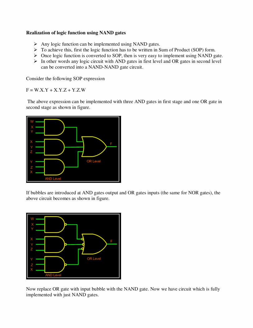
Complementary Metal Oxide Semiconductor Logic
CMOS or Complementary Metal Oxide Semiconductor logic is built using both NMOS and
PMOS. Below is the basic CMOS inverter circuit, which follows these rules:
• NMOS conducts when its input is HIGH.
• PMOS conducts when its input is LOW.
So when input is HIGH, NMOS conducts, and thus output is LOW; when input is LOW PMOS
conducts and thus output is HIGH.
THREE STATE GATES
� A three state gate is a digital circuit that exhibits three states.
� Two states are equivalent to logic 0 and 1.
� The third state is a high impedance state which is controlled by a control input C.
� The most commonly used 3-state gate is the buffer.
� The output Y = A when C =1 and is high impedance state when C = 0.
� It is possible to implement multiplexers using 3-state buffers as shown.
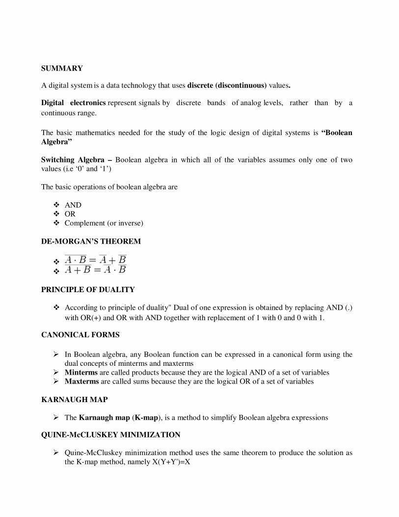
SUMMARY
A digital system is a data technology that uses discrete (discontinuous) values.
Digital electronics represent signals by discrete bands of analog levels, rather than by a
continuous range.
The basic mathematics needed for the study of the logic design of digital systems is “Boolean
Algebra”
Switching Algebra – Boolean algebra in which all of the variables assumes only one of two
values (i.e ‘0’ and ‘1’)
The basic operations of boolean algebra are
� AND
� OR
� Complement (or inverse)
DE-MORGAN’S THEOREM
�
�
PRINCIPLE OF DUALITY
� According to principle of duality" Dual of one expression is obtained by replacing AND (.)
with OR(+) and OR with AND together with replacement of 1 with 0 and 0 with 1.
CANONICAL FORMS
� In Boolean algebra, any Boolean function can be expressed in a canonical form using the
dual concepts of minterms and maxterms
� Minterms are called products because they are the logical AND of a set of variables
� Maxterms are called sums because they are the logical OR of a set of variables
KARNAUGH MAP
� The Karnaugh map (K-map), is a method to simplify Boolean algebra expressions
QUINE-McCLUSKEY MINIMIZATION
� Quine-McCluskey minimization method uses the same theorem to produce the solution as
the K-map method, namely X(Y+Y')=X

Hardware Description Language (HDL)
HDL is defined as a language that describes the hardware of digital systems in a textual form.
HDL is used to represent:
⇒Logic diagrams
⇒Boolean expressions
⇒More complex digital circuits
LOGIC GATES
� A logic gate is an electronic circuit/device which makes the logical decisions.
� To arrive at this decisions, the most common logic gates used are OR, AND, NOT, NAND,
and NOR gates.
� The NAND and NOR gates are called universal gates.
� The exclusive-OR gate is another logic gate which can be constructed using AND, OR and
NOT gate.
TRANSISTOR TRANSISTOR LOGIC
In Transistor Transistor logic or just TTL, logic gates are built only around transistors.
There are many versions or families of TTL.
• Standard TTL.
• High Speed TTL
• Low Power TTL.
• Schhottky TTL.
COMPLEMENTARY METAL OXIDE SEMICONDUCTOR LOGIC
• CMOS or Complementary Metal Oxide Semiconductor logic is built using both NMOS and
PMOS

REVIEW QUESTIONS
Objectives
1. The output expression for an AND-OR circuit having one AND gate with inputs A,B,C and D
and one AND gate with inputs E and F is
a. ABCDEF b. A+B+C+D+E+F
c. (A+B+C+D)(E+F) d. ABCD + EF
2. A logic circuit with an output X = AB’C + AC’ consists of
a. two AND gates and one OR gate
b. two AND gates, one OR gate and two inverters
c. two OR gates, one AND gate and two inverters
d. two AND gates, one OR gate and one inverter
3. To implement the expression A’BCD+AB’CD+ABC’D’, it takes one OR gate and
a. one AND gate
b. three AND gates
c. three AND gates and four inverters
d. three AND gates and three inverters
4. The expression A’BCD+ABCD’+AB’C’D
a. cannot be simplified
b. can be simplified to A’BC+AB’
c. can be simplified to ABCD’+A’BC’
d. None of these answers is correct
5. An Exclusive OR function is expressed as
a. A’B’+AB b. A’B+AB’
c. (A’+B)(A+B’) d. (A’+B’)+(A+B)
6. The AND operation can be produced with
a. Two NAND gates b. three NAND gates
c. One NOR gate d. two NOR gates
7. All Boolean expressions can be implemented with
a. NAND gates only
b. NOR gates only
c. Combination of AND gates, OR gates and inverters
d. any of these
8. According to DeMorgan’s theorems, the following equality(s) are correct
a. (AB)’ = A’+B’ b. (XYZ)’ = X’+Y’+Z’
c. (A+B+C)’ = A’B’C’ d. all of these

9. The Boolean expression AB’CD’ is
a. a sum term b. a product term
c. a literal term d. always 1
10. Which of the following rule states that if one input of an AND gate is always 1, the output is
equal to the other input?
a. A+1 =1 b. A+A = A
c. A.A = A d. A.1 = A
11. An example of standard SOP expression is
a. A’B+AB’C+ABD’ b. AB’C+AC’D
c. AB’+A’B+AB d. AB’CD’+A’B+A’
12. The minimized form of the logical expression (A’B’C’+A’BC’+A’BC+ABC’) is
a. A’C’+BC’+A’B b. AC’+B’C+A’B
c. A’C+B’C+A’B d. AC’+B’C+AB’
13. If X= 1 in the logic equation [X+Z{Y’+(Z’+XY’)}]{X’+Z’(X+Y)} = 1 , then
a. Y = Z b. Y = Z’
c. Z = 1 d. Z = 0
14. The output of a logic gate is 1 when all its inputs are at logic 0. Then gate is either
a. a NAND or an EXOR gate b. a NOR or an EXNOR gate
c. an OR or an EXNOR gate d. an AND or an EXOR gate
15. The Boolean function A+BC is reduced form of
a. AB+BC b. (A+B) (A+C)
c. A’B+AB’C d. (A+C) B
2- marks
Short Questions
1 What is the basic difference between analog and digital systems?
2. Why are digital systems capable of greater accuracy than analog systems?
Answers for Self Test
1. d 2. b 3. c 4. a 5. b 6. a
7. d 8. d 9. b 10. d 11. c 12. a
13. d 14. b 15. b

2- marks
1. Why are binary numbers used in digital systems?
2. Write the laws and postulates of boolean algebra?
3. Define Demorgan’s Theorem.
4. Define logic gate.
5. Write the truth table for all logic gates.
6. Express x+yz as the sum of minterms.
7. What is prime implicant?
8. Find the value of X = A B C (A+D) if A=0; B=1; C=1 and D=1.
9. What are ‘minterms’ and ‘maxterms’?
10. State and prove Demorgan’s theorem.
11. Find the complement of x+yz.
12. Define the following : Minterm and Maxterm
13. State and prove Consensus theorem.
14. What theorem is used when two terms in adjacent squares of K map are combined?
15. How will you use a 4 input NAND gate as a 2 input NAND gate?
16. How will you use a 4 input NOR gate as a 2 input NOR gate?
17. Show that the NAND connection is not associative.
18. What happens when all the gates is a two level AND-OR gate network are replaced by
NOR gates?
19. What is meant by multilevel gates networks?
20. Show that the NAND gate is a universal building block.
21. Show that a positive logic NAND gate is the same as a negative logic NOT gate.
22. Distinguish between positive logic and negative logic.
23. What is the exact number of bytes in a system that contains (a) 32K byte, (b) 64M bytes,
and (c) 6.4G byte?
24. List the truth table of the function:
F = x y + x y’ + y ’z
Big Questions
1. Draw a circuit that uses only one AND gate and one OR gate to realize each of the
following functions:
(a) (A+B+C+D) (A+B+C+E) (A+B+C+F)
(b) WXYZ + VXYZ + UXYZ
2. Draw a circuit to realize the function:
(a) F = ABC + A'BC + AB'C + ABC'
(a) using one OR gate and three AND gates. The AND gate gates should have two
inputs
(b) using two OR gates and two AND gates. All of the gates should have two inputs.
3. List out the classifications of the digital logical families.
4. Explain TTL logic and their characteristics.
5. Explain about tristate gates.

6. For each of the following functions, find all the prime implicants, using the Quine-
McCluskey method.
(a) f(a,b,c,d) = ∑ m (1,5,7,9,11,12,14,15)
(b) f(a,b,c,d) = ∑ m (0,1,3,5,6,7,8,10,14,15)
7. State and prove the postulates of Boolean algebra
8. Find a Min SOP and Min POS for f = b’c’d + bcd + acd’ + a’b’c + a’bc’d
9. Find an expression for the following function usingQuine McCluscky method F= ∑ (0, 2,
3,5,7,9,11,13,14,16,18,24,26,28,30).
10. State and prove the theorems of Boolean algebra with illustration.
11. Find the MSP representation for F(A,B,C,D,E) = ∑m(1,4,6,10,20,22,24,26) + ∑d
(0,11,16,27) using K-Map method.
12. (a) Prove that (x1+x2)(x1’x3’+x3) (x2’ + x1x3) =x1’x2.
(c) Simplify using K-map to obtain a minimum POS expression:
(a) (A’ + B’+C+D) (A+B’+C+D) (A+B+C+D’) (A+B+C’+D’) (A’+B+C’+D’)
(b) (A+B+C’+D)