Embed Size (px)
Citation preview
VOL. 12, NO. 17, SEPTEMBER 2017 ISSN 1819-6608
ARPN Journal of Engineering and Applied Sciences ©2006-2017 Asian Research Publishing Network (ARPN). All rights reserved.
www.arpnjournals.com
4940
DESIGN AND ANALYSIS OF TOOL WEAR CHARACTERISTICS DURING TURNING USING DEFORM 3D
R. Rajesh, J. Lilly Mercy, S. Ravikumar and Akanksha Singh School of Mechanical Engineering, Sathyabama University, Chennai, India
E-Mail: [email protected]
ABSTRACT
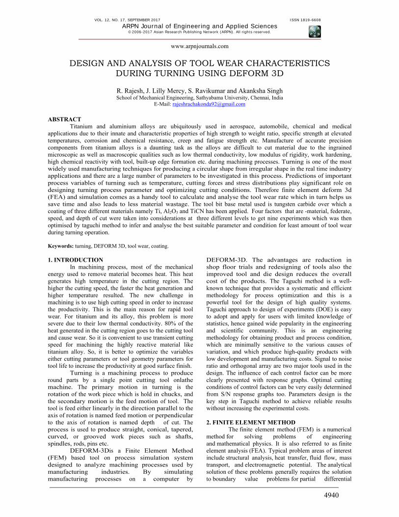
Titanium and aluminium alloys are ubiquitously used in aerospace, automobile, chemical and medical applications due to their innate and characteristic properties of high strength to weight ratio, specific strength at elevated temperatures, corrosion and chemical resistance, creep and fatigue strength etc. Manufacture of accurate precision components from titanium alloys is a daunting task as the alloys are difficult to cut material due to the ingrained microscopic as well as macroscopic qualities such as low thermal conductivity, low modulus of rigidity, work hardening, high chemical reactivity with tool, built-up edge formation etc. during machining processes. Turning is one of the most widely used manufacturing techniques for producing a circular shape from irregular shape in the real time industry applications and there are a large number of parameters to be investigated in this process. Predictions of important process variables of turning such as temperature, cutting forces and stress distributions play significant role on designing turning process parameter and optimizing cutting conditions. Therefore finite element deform 3d (FEA) and simulation comes as a handy tool to calculate and analyse the tool wear rate which in turn helps us save time and also leads to less material wastage. The tool bit base metal used is tungsten carbide over which a coating of three different materials namely Ti, Al2O3 and TiCN has been applied. Four factors that are -material, federate, speed, and depth of cut were taken into considerations at three different levels to get nine experiments which was then optimised by taguchi method to infer and analyse the best suitable parameter and condition for least amount of tool wear during turning operation. Keywords: turning, DEFORM 3D, tool wear, coating. 1. INTRODUCTION
In machining process, most of the mechanical energy used to remove material becomes heat. This heat generates high temperature in the cutting region. The higher the cutting speed, the faster the heat generation and higher temperature resulted. The new challenge in machining is to use high cutting speed in order to increase the productivity. This is the main reason for rapid tool wear. For titanium and its alloy, this problem is more severe due to their low thermal conductivity. 80% of the heat generated in the cutting region goes to the cutting tool and cause wear. So it is convenient to use transient cutting speed for machining the highly reactive material like titanium alloy. So, it is better to optimize the variables either cutting parameters or tool geometry parameters for tool life to increase the productivity at good surface finish.
Turning is a machining process to produce round parts by a single point cutting tool onlathe machine. The primary motion in turning is the rotation of the work piece which is hold in chucks, and the secondary motion is the feed motion of tool. The tool is feed either linearly in the direction parallel to the axis of rotation is named feed motion or perpendicular to the axis of rotation is named depth of cut. The process is used to produce straight, conical, tapered, curved, or grooved work pieces such as shafts, spindles, rods, pins etc.
DEFORM-3Dis a Finite Element Method (FEM) based tool on process simulation system designed to analyze machining processes used by manufacturing industries. By simulating manufacturing processes on a computer by
DEFORM-3D. The advantages are reduction in shop floor trials and redesigning of tools also the improved tool and die design reduces the overall cost of the products. The Taguchi method is a well-known technique that provides a systematic and efficient methodology for process optimization and this is a powerful tool for the design of high quality systems. Taguchi approach to design of experiments (DOE) is easy to adopt and apply for users with limited knowledge of statistics, hence gained wide popularity in the engineering and scientific community. This is an engineering methodology for obtaining product and process condition, which are minimally sensitive to the various causes of variation, and which produce high-quality products with low development and manufacturing costs. Signal to noise ratio and orthogonal array are two major tools used in the design. The influence of each control factor can be more clearly presented with response graphs. Optimal cutting conditions of control factors can be very easily determined from S/N response graphs too. Parameters design is the key step in Taguchi method to achieve reliable results without increasing the experimental costs. 2. FINITE ELEMENT METHOD
The finite element method (FEM) is a numerical method for solving problems of engineering and mathematical physics. It is also referred to as finite element analysis (FEA). Typical problem areas of interest include structural analysis, heat transfer, fluid flow, mass transport, and electromagnetic potential. The analytical solution of these problems generally requires the solution to boundary value problems for partial differential
VOL. 12, NO. 17, SEPTEMBER 2017 ISSN 1819-6608
ARPN Journal of Engineering and Applied Sciences ©2006-2017 Asian Research Publishing Network (ARPN). All rights reserved.
www.arpnjournals.com
4941
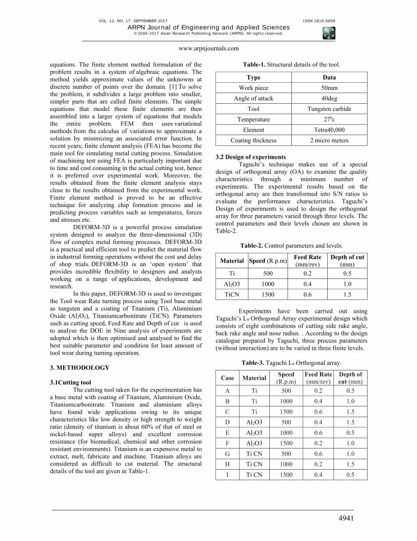
equations. The finite element method formulation of the problem results in a system of algebraic equations. The method yields approximate values of the unknowns at discrete number of points over the domain. [1] To solve the problem, it subdivides a large problem into smaller, simpler parts that are called finite elements. The simple equations that model these finite elements are then assembled into a larger system of equations that models the entire problem. FEM then uses variational methods from the calculus of variations to approximate a solution by minimizing an associated error function. In recent years; finite element analysis (FEA) has become the main tool for simulating metal cutting process. Simulation of machining test using FEA is particularly important due to time and cost consuming in the actual cutting test, hence it is preferred over experimental work. Moreover, the results obtained from the finite element analysis stays close to the results obtained from the experimental work. Finite element method is proved to be an effective technique for analyzing chip formation process and in predicting process variables such as temperatures, forces and stresses etc.
DEFORM-3D is a powerful process simulation system designed to analyze the three-dimensional (3D) flow of complex metal forming processes. DEFORM-3D is a practical and efficient tool to predict the material flow in industrial forming operations without the cost and delay of shop trials. DEFORM-3D is an ‘open system’ that provides incredible flexibility to designers and analysts working on a range of applications, development and research.
In this paper, DEFORM-3D is used to investigate the Tool wear Rate turning process using Tool base metal as tungsten and a coating of Titanium (Ti), Aluminium Oxide (Al2O3), Titaniumcarbonitrate (TiCN). Parameters such as cutting speed, Feed Rate and Depth of cut is used to analyse the DOE in Nine analysis of experiments are adopted which is then optimised and analysed to find the best suitable parameter and condition for least amount of tool wear during turning operation. 3. METHODOLOGY 3.1Cutting tool
The cutting tool taken for the experimentation has a base metal with coating of Titanium, Aluminium Oxide, Titaniumcarbonitrate. Titanium and aluminium alloys have found wide applications owing to its unique characteristics like low density or high strength to weight ratio (density of titanium is about 60% of that of steel or nickel-based super alloys) and excellent corrosion resistance (for biomedical, chemical and other corrosion resistant environments). Titanium is an expensive metal to extract, melt, fabricate and machine. Titanium alloys are considered as difficult to cut material. The structural details of the tool are given in Table-1.
Table-1. Structural details of the tool.
Type Data
Work piece 50mm
Angle of attack 40deg
Tool Tungsten carbide
Temperature 270c
Element Tetra40,000
Coating thickness 2 micro meters
3.2 Design of experiments
Taguchi’s technique makes use of a special design of orthogonal array (OA) to examine the quality characteristics through a minimum number of experiments. The experimental results based on the orthogonal array are then transformed into S/N ratios to evaluate the performance characteristics. Taguchi’s Design of experiments is used to design the orthogonal array for three parameters varied through three levels. The control parameters and their levels chosen are shown in Table-2.
Table-2. Control parameters and levels.
Material Speed (R.p.m)Feed Rate (mm/rev)
Depth of cut (mm)
Ti 500 0.2 0.5
Al2O3 1000 0.4 1.0
TiCN 1500 0.6 1.5
Experiments have been carried out using
Taguchi’s L9 Orthogonal Array experimental design which consists of eight combinations of cutting side rake angle, back rake angle and nose radius. . According to the design catalogue prepared by Taguchi, three process parameters (without interaction) are to be varied in three finite levels.
Table-3. Taguchi L9 Orthogonal array.
Case MaterialSpeed
(R.p.m) Feed Rate (mm/rev)
Depth of cut (mm)
A Ti 500 0.2 0.5
B Ti 1000 0.4 1.0
C Ti 1500 0.6 1.5
D Al2O3 500 0.4 1.5
E Al2O3 1000 0.6 0.5
F Al2O3 1500 0.2 1.0
G Ti CN 500 0.6 1.0
H Ti CN 1000 0.2 1.5
I Ti CN 1500 0.4 0.5

VOL. 12, NO. 17, SEPTEMBER 2017 ISSN 1819-6608
ARPN Journal of Engineering and Applied Sciences ©2006-2017 Asian Research Publishing Network (ARPN). All rights reserved.
www.arpnjournals.com
4942
3.3 Computing software DEFORM-3D is a computer aided engineering
(CAE), machining simulation and analysis software. It uses Usui’s tool wear model to compute cutting inserts flank wear, which is used only with non-isothermal run, as it requires interface temperature calculations. The initial temperature for the work piece and tool is set as270 C (room temperature). Turning mo d e l l i n g procedures in DEFROM-3D software enable to study the process response for any change in process conditions. The effect o f process parameters i.e. cutting speed, feed rate and depth of cut on the process response i.e. cutting forces, temperatures or stress etc can be study by it. For turning of work piece, the relationship with insert to the
analysis domain is shown in figure (figure number) Simulations are carried out to reach the transient condition and then transformed to steady-state condition. Tool stress analysis is performed to obtain maximum principal stresses acting on the cutting inserts. The cutting insert is a rigid object, which turns a metal (name to be specified) work piece. During simulation the length of work piece to be machined is fixed. During meshing of cutting inserts, the number of tetrahedron elements is fixed as 40,000, while the number of elements in work piece is kept in accordance of feed rate. During meshing, a smooth mesh can be seen at tool tip and in the work piece, where the tool comes in contact with the work piece.
Figure-1. Layout of the turning process. 4. RESULT AND DISCUSSIONS
DEFORM 3D software is used to done by the Experimental Analysis and the growing chip removal of the Work piece by the tool, a rigid object meshed with 40,000 elements, is oriented according to the cutting speed, Feed rate and Depth of cut in experimental test and moves along the feed direction. The analysis is run by the different parameters of Speed, Feed rate, Depth of cut and different metal coating after completing Analysis. The Main Level Result are selected based up on the this Result Which parameter is Suitable for good finishing of Tool Wear rate the Analysis Result cases( A to I) they are a) Damage
b) Effective strain
c) Effective stress
d) Total Velocity
e) Total Displacement
f) Normal Pressure
g) Temperature
h) Folding Angle
i) Tool Wear
j) Total Force
k) Maximum Shear Force
4.1 Damage It is the observed the maximum Damage in the
Tool wear rate occurs when the material coating used is
VOL. 12, NO. 17, SEPTEMBER 2017 ISSN 1819-6608
ARPN Journal of Engineering and Applied Sciences ©2006-2017 Asian Research Publishing Network (ARPN). All rights reserved.
www.arpnjournals.com
4943
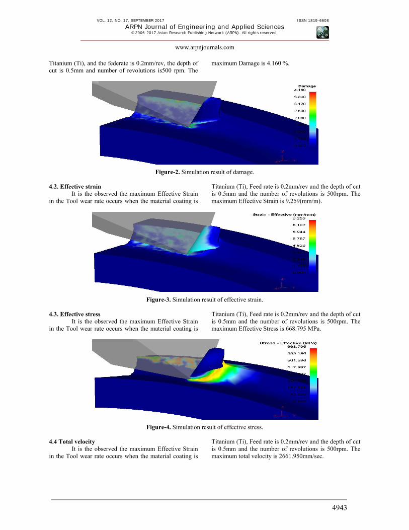
Titanium (Ti), and the federate is 0.2mm/rev, the depth of cut is 0.5mm and number of revolutions is500 rpm. The
maximum Damage is 4.160 %.
Figure-2. Simulation result of damage. 4.2. Effective strain
It is the observed the maximum Effective Strain in the Tool wear rate occurs when the material coating is
Titanium (Ti), Feed rate is 0.2mm/rev and the depth of cut is 0.5mm and the number of revolutions is 500rpm. The maximum Effective Strain is 9.259(mm/m).
Figure-3. Simulation result of effective strain. 4.3. Effective stress
It is the observed the maximum Effective Strain in the Tool wear rate occurs when the material coating is
Titanium (Ti), Feed rate is 0.2mm/rev and the depth of cut is 0.5mm and the number of revolutions is 500rpm. The maximum Effective Stress is 668.795 MPa.
Figure-4. Simulation result of effective stress. 4.4 Total velocity
It is the observed the maximum Effective Strain in the Tool wear rate occurs when the material coating is
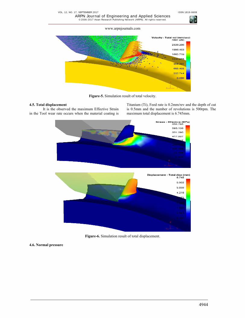
Titanium (Ti), Feed rate is 0.2mm/rev and the depth of cut is 0.5mm and the number of revolutions is 500rpm. The maximum total velocity is 2661.950mm/sec.
VOL. 12, NO. 17, SEPTEMBER 2017 ISSN 1819-6608
ARPN Journal of Engineering and Applied Sciences ©2006-2017 Asian Research Publishing Network (ARPN). All rights reserved.
www.arpnjournals.com
4944
Figure-5. Simulation result of total velocity. 4.5. Total displacement
It is the observed the maximum Effective Strain in the Tool wear rate occurs when the material coating is
Titanium (Ti), Feed rate is 0.2mm/rev and the depth of cut is 0.5mm and the number of revolutions is 500rpm. The maximum total displacement is 6.745mm.
Figure-6. Simulation result of total displacement. 4.6. Normal pressure
VOL. 12, NO. 17, SEPTEMBER 2017 ISSN 1819-6608
ARPN Journal of Engineering and Applied Sciences ©2006-2017 Asian Research Publishing Network (ARPN). All rights reserved.
www.arpnjournals.com
4945
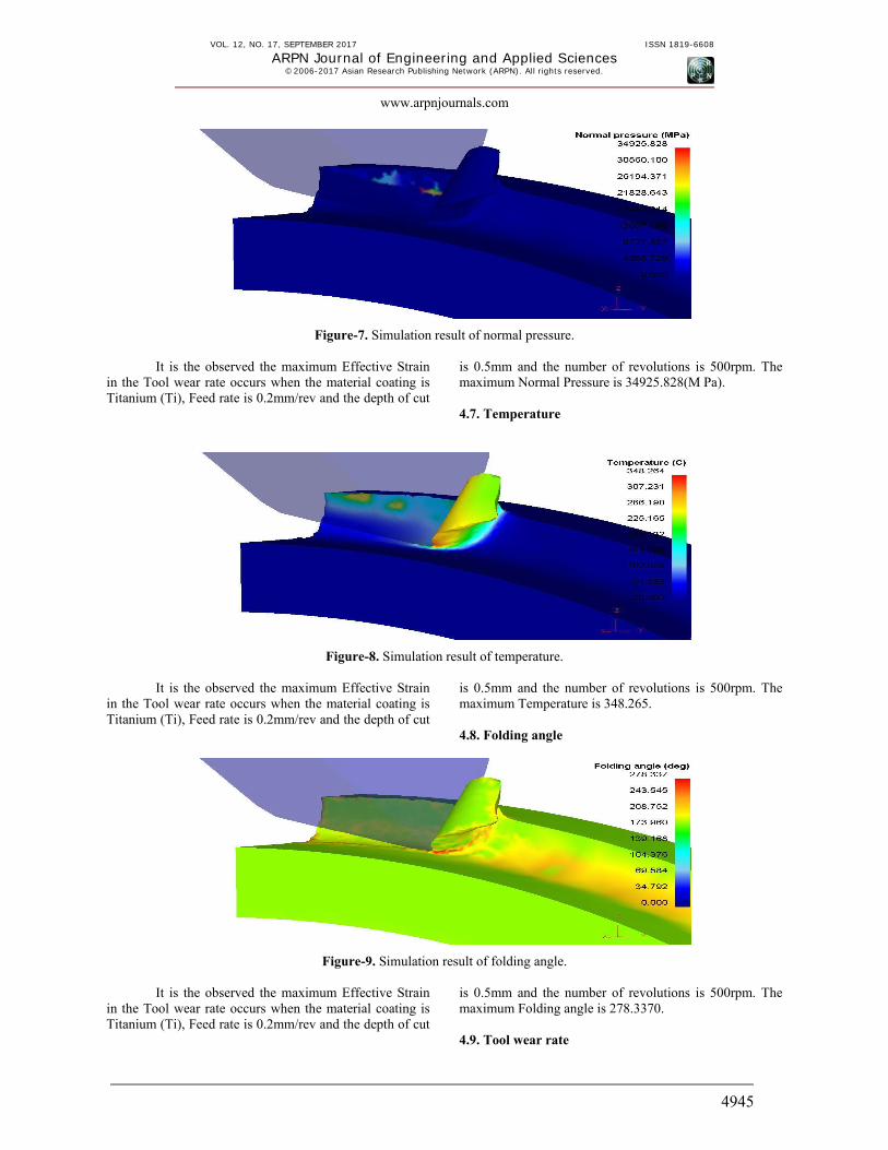
Figure-7. Simulation result of normal pressure.
It is the observed the maximum Effective Strain in the Tool wear rate occurs when the material coating is Titanium (Ti), Feed rate is 0.2mm/rev and the depth of cut
is 0.5mm and the number of revolutions is 500rpm. The maximum Normal Pressure is 34925.828(M Pa). 4.7. Temperature
Figure-8. Simulation result of temperature.
It is the observed the maximum Effective Strain in the Tool wear rate occurs when the material coating is Titanium (Ti), Feed rate is 0.2mm/rev and the depth of cut
is 0.5mm and the number of revolutions is 500rpm. The maximum Temperature is 348.265. 4.8. Folding angle
Figure-9. Simulation result of folding angle.
It is the observed the maximum Effective Strain in the Tool wear rate occurs when the material coating is Titanium (Ti), Feed rate is 0.2mm/rev and the depth of cut
is 0.5mm and the number of revolutions is 500rpm. The maximum Folding angle is 278.3370. 4.9. Tool wear rate
VOL. 12, NO. 17, SEPTEMBER 2017 ISSN 1819-6608
ARPN Journal of Engineering and Applied Sciences ©2006-2017 Asian Research Publishing Network (ARPN). All rights reserved.
www.arpnjournals.com
4946
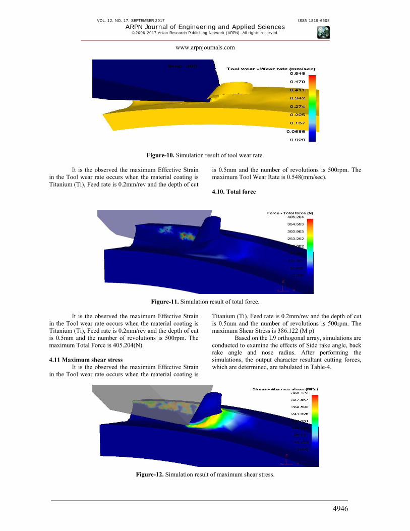
Figure-10. Simulation result of tool wear rate.
It is the observed the maximum Effective Strain in the Tool wear rate occurs when the material coating is Titanium (Ti), Feed rate is 0.2mm/rev and the depth of cut
is 0.5mm and the number of revolutions is 500rpm. The maximum Tool Wear Rate is 0.548(mm/sec). 4.10. Total force
Figure-11. Simulation result of total force.
It is the observed the maximum Effective Strain in the Tool wear rate occurs when the material coating is Titanium (Ti), Feed rate is 0.2mm/rev and the depth of cut is 0.5mm and the number of revolutions is 500rpm. The maximum Total Force is 405.204(N). 4.11 Maximum shear stress
It is the observed the maximum Effective Strain in the Tool wear rate occurs when the material coating is
Titanium (Ti), Feed rate is 0.2mm/rev and the depth of cut is 0.5mm and the number of revolutions is 500rpm. The maximum Shear Stress is 386.122 (M p)
Based on the L9 orthogonal array, simulations are conducted to examine the effects of Side rake angle, back rake angle and nose radius. After performing the simulations, the output character resultant cutting forces, which are determined, are tabulated in Table-4.
Figure-12. Simulation result of maximum shear stress.
VOL. 12, NO. 17, SEPTEMBER 2017 ISSN 1819-6608
ARPN Journal of Engineering and Applied Sciences ©2006-2017 Asian Research Publishing Network (ARPN). All rights reserved.
www.arpnjournals.com
4947
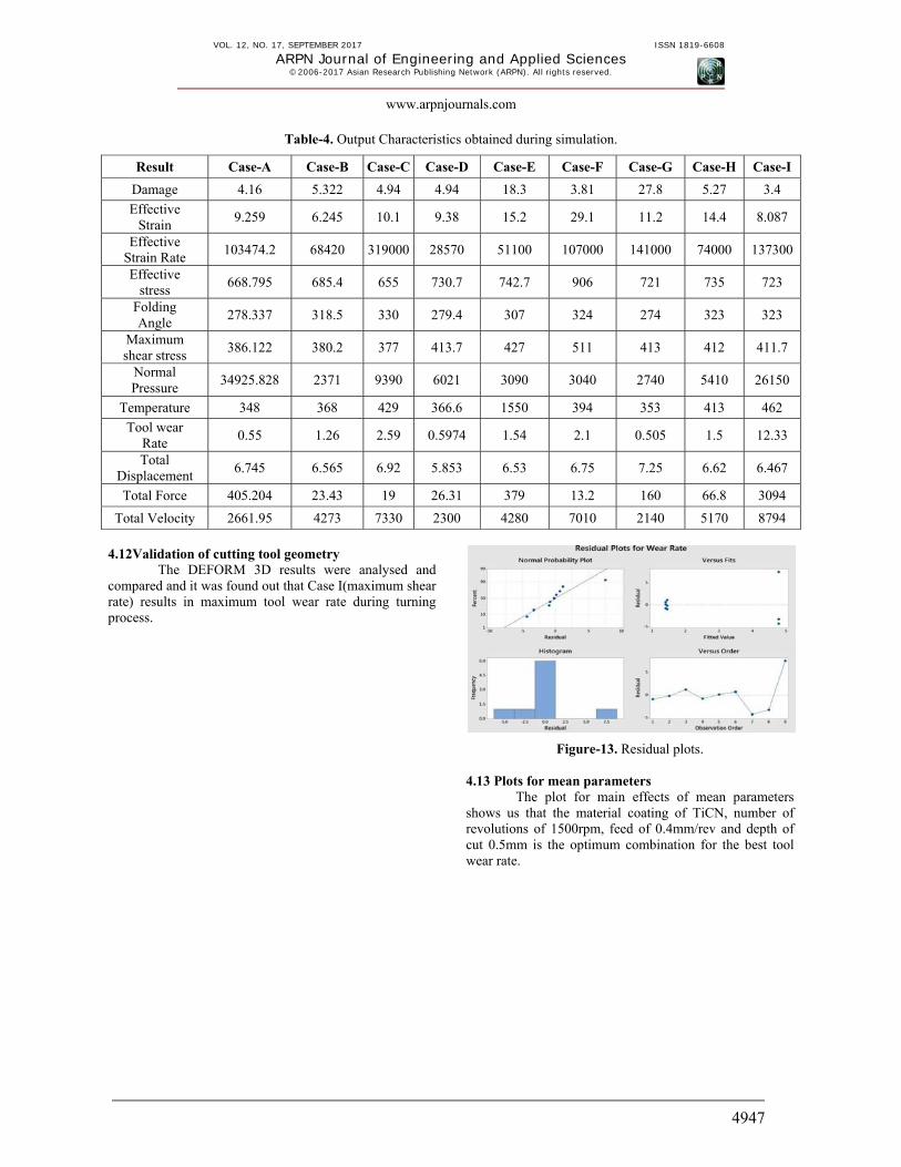
Table-4. Output Characteristics obtained during simulation.
Result Case-A Case-B Case-C Case-D Case-E Case-F Case-G Case-H Case-I
Damage 4.16 5.322 4.94 4.94 18.3 3.81 27.8 5.27 3.4
Effective Strain
9.259 6.245 10.1 9.38 15.2 29.1 11.2 14.4 8.087
Effective Strain Rate
103474.2 68420 319000 28570 51100 107000 141000 74000 137300
Effective stress
668.795 685.4 655 730.7 742.7 906 721 735 723
Folding Angle
278.337 318.5 330 279.4 307 324 274 323 323
Maximum shear stress
386.122 380.2 377 413.7 427 511 413 412 411.7
Normal Pressure
34925.828 2371 9390 6021 3090 3040 2740 5410 26150
Temperature 348 368 429 366.6 1550 394 353 413 462
Tool wear Rate
0.55 1.26 2.59 0.5974 1.54 2.1 0.505 1.5 12.33
Total Displacement
6.745 6.565 6.92 5.853 6.53 6.75 7.25 6.62 6.467
Total Force 405.204 23.43 19 26.31 379 13.2 160 66.8 3094
Total Velocity 2661.95 4273 7330 2300 4280 7010 2140 5170 8794
4.12Validation of cutting tool geometry
The DEFORM 3D results were analysed and compared and it was found out that Case I(maximum shear rate) results in maximum tool wear rate during turning process.
Figure-13. Residual plots. 4.13 Plots for mean parameters
The plot for main effects of mean parameters shows us that the material coating of TiCN, number of revolutions of 1500rpm, feed of 0.4mm/rev and depth of cut 0.5mm is the optimum combination for the best tool wear rate.

VOL. 12, NO. 17, SEPTEMBER 2017 ISSN 1819-6608
ARPN Journal of Engineering and Applied Sciences ©2006-2017 Asian Research Publishing Network (ARPN). All rights reserved.
www.arpnjournals.com
4948
Figure-14. Main effect plot for means. 4.14 Plot of wear rate vs. material
Figure-15. Wear rate vs material.
The Wear rate vs. Material Plot shows that the wear rate is steady and same for the coatings of Aluminium Oxide and Titanium (at a wear rate of 2.5%)
and increases gradually for titanium carbo nitride (at a wear rate of5%). 4.15 Damage vs. time graph
Figure-16. Damage vs time.
VOL. 12, NO. 17, SEPTEMBER 2017 ISSN 1819-6608
ARPN Journal of Engineering and Applied Sciences ©2006-2017 Asian Research Publishing Network (ARPN). All rights reserved.
www.arpnjournals.com
4949
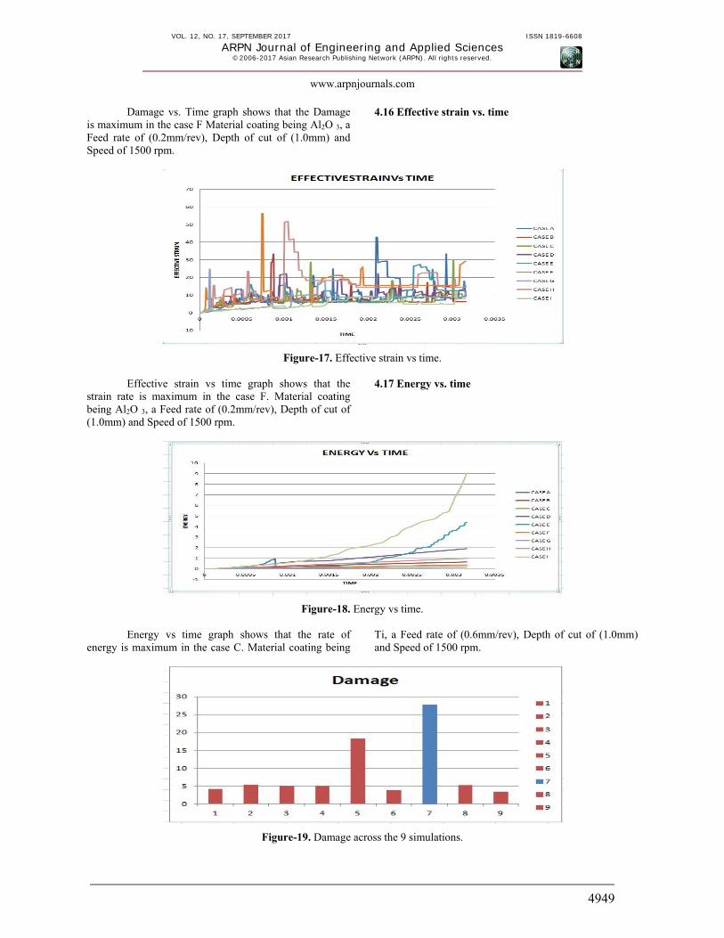
Damage vs. Time graph shows that the Damage is maximum in the case F Material coating being Al2O 3, a Feed rate of (0.2mm/rev), Depth of cut of (1.0mm) and Speed of 1500 rpm.
4.16 Effective strain vs. time
Figure-17. Effective strain vs time.
Effective strain vs time graph shows that the strain rate is maximum in the case F. Material coating being Al2O 3, a Feed rate of (0.2mm/rev), Depth of cut of (1.0mm) and Speed of 1500 rpm.
4.17 Energy vs. time
Figure-18. Energy vs time.
Energy vs time graph shows that the rate of energy is maximum in the case C. Material coating being
Ti, a Feed rate of (0.6mm/rev), Depth of cut of (1.0mm) and Speed of 1500 rpm.
Figure-19. Damage across the 9 simulations.
VOL. 12, NO. 17, SEPTEMBER 2017 ISSN 1819-6608
ARPN Journal of Engineering and Applied Sciences ©2006-2017 Asian Research Publishing Network (ARPN). All rights reserved.
www.arpnjournals.com
4950
Figure-19 represents that the maximum Damage occurs in case-G. The combination of parameters is Ti CN material coating, speed is 500r.p.m, Feed Rate is 0.6 mm/rev and Depth of cut is 1.0mm.
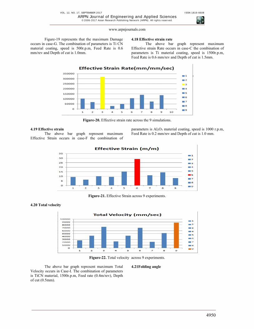
4.18 Effective strain rate The above bar graph represent maximum
Effective strain Rate occurs in case-C the combination of parameters is Ti material coating, speed is 1500r.p.m, Feed Rate is 0.6 mm/rev and Depth of cut is 1.5mm.
Figure-20. Effective strain rate across the 9 simulations. 4.19 Effective strain
The above bar graph represent maximum Effective Strain occurs in case-F the combination of
parameters is Al2O3 material coating, speed is 1000 r.p.m, Feed Rate is 0.2 mm/rev and Depth of cut is 1.0 mm.
Figure-21. Effective Strain across 9 experiments. 4.20 Total velocity
Figure-22. Total velocity across 9 experiments.
The above bar graph represent maximum Total Velocity occurs in Case-I. The combination of parameters is TiCN material, 1500r.p.m, Feed rate (0.4m/rev), Depth of cut (0.5mm).
4.21Folding angle
VOL. 12, NO. 17, SEPTEMBER 2017 ISSN 1819-6608
ARPN Journal of Engineering and Applied Sciences ©2006-2017 Asian Research Publishing Network (ARPN). All rights reserved.
www.arpnjournals.com
4951
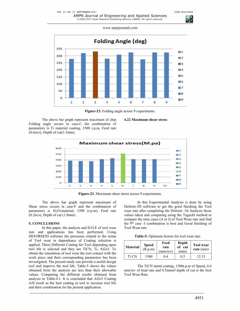
Figure-23. Folding angle across 9 experiments.
The above bar graph represent maximum of chip Folding angle occurs in case-C the combination of parameters is Ti material coating, 1500 r.p.m, Feed rate (0.6m/s), Depth of cut(1.5mm).
4.22 Maximum shear stress
Figure-23. Maximum shear stress across 9 experiments.
The above bar graph represent maximum of Shear stress occurs in case-F and the combination of parameters is Al2O3material, 1500 (r.p.m), Feed rate (0.2m/s), Depth of cut (1.0mm). 5. CONCLUSIONS
In this paper, the analysis and D.O.E of tool wear rate and applications has been performed. Using DEFORM3D software the processes related to the terms of Tool wear in dependence of Coating selection is applied. Three Different Coating for Tool depending upon tool life is selected and they are TiCN, Ti, Al2o3. To obtain the simulation of tool wear the tool contact with the work piece and their corresponding parameters has been investigated. The present study can provide a useful design tool and improve the tool life. Table-5 shows the values obtained from the analysis are less than their allowable values. Comparing the different results obtained from analysis in Table-4.1. It is concluded that Al2o3 Coating will result as the best coating in tool to increase tool life and their combination for the present application.
In this Experimental Analysis is done by using Deform-3D software to get the good finishing the Tool wear rate after completing the Deform -3d Analysis those values taken and comparing using the Taguchi method to compare the nine cases (A to I) of Tool Wear rate and find the 9th case -I combination is best and Good finishing of Tool Wear rate.
Table-5. Optimum factors for tool wear rate.
MaterialSpeed
(R.p.m)
Feed rate
(mm/rev)
Depth of cut (mm)
Tool wear rate (mm)
Ti CN 1500 0.4 0.5 12.33
The TiCN metal coating, 1500r.p.m of Speed, 0.4
mm/rev of feed rate and 0.5mmof depth of cut is the best Tool Wear Rate.
VOL. 12, NO. 17, SEPTEMBER 2017 ISSN 1819-6608
ARPN Journal of Engineering and Applied Sciences ©2006-2017 Asian Research Publishing Network (ARPN). All rights reserved.
www.arpnjournals.com
4952
REFERENCES [1] A. Ginting. 2007. Finite Element Method Applied on
Metal Cutting: from Chip Formation to Coating Delimitation by Tribe-Energetic Approach, J. Teknologi Proses. 6: 59-69.
[2] Ceretti E., Lazzaroni C., Menegardo L. and Altan T. 2000. Turning simulations using a three-dimensional FEM code. Journal of Materials Processing Technology. 98: 99-103.
[3] Domenico Umbrello. 2008. Finite element simulation of conventional and high speed machining of Ti6A14V alloy. Journal of materials processing technology. 96: 79-87.
[4] F Klocke, S Hoppe. 2003. Simulation of the metal cutting process-reliability and optimization. International Journal of Production Engineering and Computers. 4: 43-52.
[5] Halil Bil, S Engin Kilic, A Erman Tekkaya. 2004. A comparison of orthogonal cutting data from experiments with three different finite element models. International Journal of Machine Tools & Manufacture. 44: 933-944.
[6] H. B. Wu, S. J. Zhang, 3D FEM simulation of milling process for titanium alloy Ti6Al4V. The International Journal of Advanced Manufacturing Technology. 71 (2014) 1319-1326.
[7] Karpat Y. and Özel T. 2007. 3-D FEA of hard turning: investigation of PCBN cutting tool.
[8] Madalina CALAMAZ, Dominique COUPARD, Franck GIROT. 2008. A new material model for 2D numerical simulation of serrated chip formation when machining titanium alloy Ti-6Al-4V. Imitational Joumal of Machine Tools & Manufacture. 48: 275-288.
[9] Noordin M.Y., Venkatesh V.C., Sharif S., Elting S., Abdullah A. 2003. Application of response surface methodology in describing the performance of coated carbide tools when turning AISI 1045 steel Journal of Material Processing Technology. 145(1): 46-58, 200.
[10] Y. Karpat, T. Özel. 2008. Process simulations for 3D turning using uniform and variable micro geometry PCBN tools, Int. J. Machining and Mach inability of Materials. 3(3).