Embed Size (px)
Citation preview
1
Design and Construction ofAirport Concrete Pavement in JAPAN
Yukitomo TSUBOKAWA, Dr. Eng.National Institute for Land & Infrastructure Management
Ministry of Land, Infrastructure, Transport & Tourism, JAPAN
Sep 25 2012Joint Seminar on Concrete Technology
for Construction of Transportation and Civil Infrastructure(Hanoi, Vietnam)
2
Summary of Airport Concrete Pavement in JAPAN
Design of Airport Concrete PavementEmpirical Design MethodMechanistic-Empirical Design Method
Construction of Airport Concrete PavementMaterialMix DesignConstruction
Contents
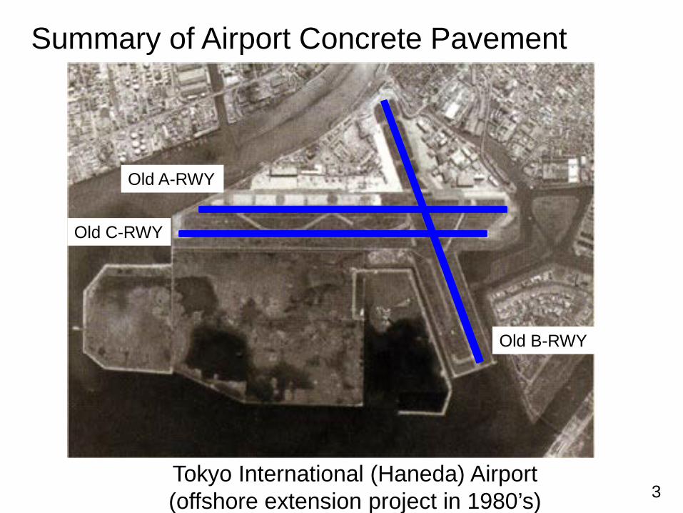
3Tokyo International (Haneda) Airport(offshore extension project in 1980’s)
Summary of Airport Concrete Pavement
Old B-RWY
Old A-RWY
Old C-RWY
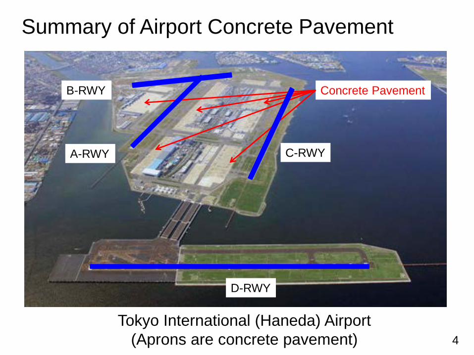
4Tokyo International (Haneda) Airport
(Aprons are concrete pavement)
Summary of Airport Concrete Pavement
D-RWY
C-RWYA-RWY
B-RWY Concrete Pavement
5
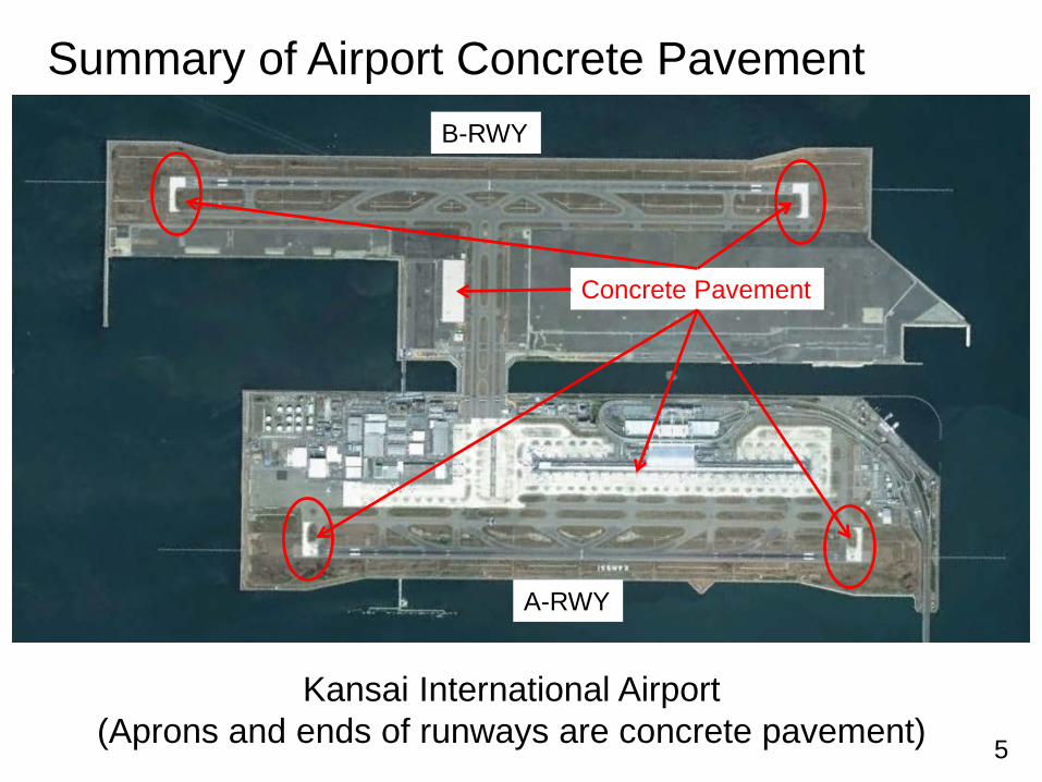
Kansai International Airport(Aprons and ends of runways are concrete pavement)
Summary of Airport Concrete Pavement
A-RWY
Concrete Pavement
B-RWY
6
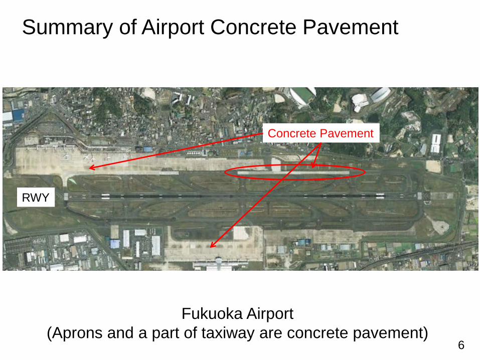
Fukuoka Airport(Aprons and a part of taxiway are concrete pavement)
Summary of Airport Concrete Pavement
Concrete Pavement
RWY
7
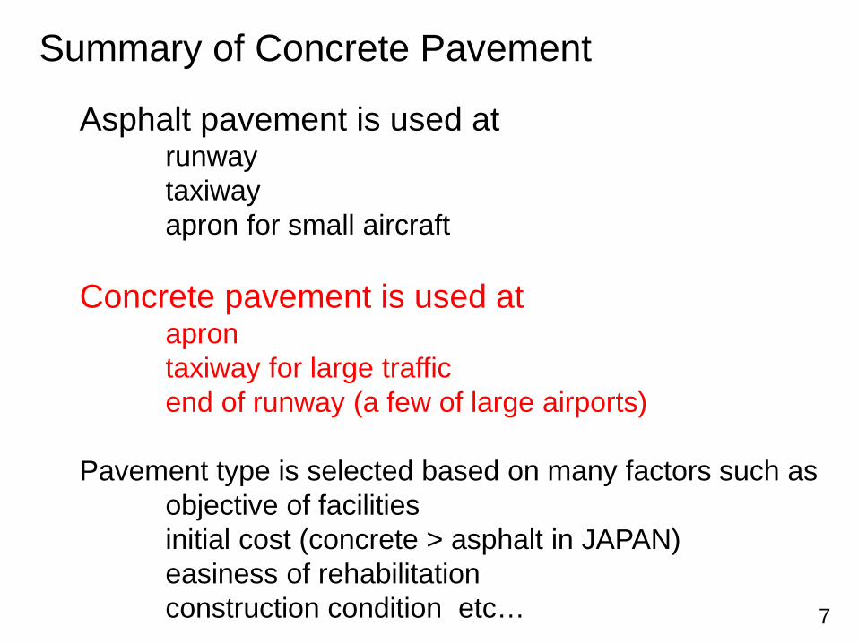
Asphalt pavement is used atrunwaytaxiwayapron for small aircraft
Concrete pavement is used ataprontaxiway for large trafficend of runway (a few of large airports)
Pavement type is selected based on many factors such asobjective of facilitiesinitial cost (concrete > asphalt in JAPAN)easiness of rehabilitationconstruction condition etc…
Summary of Concrete Pavement
8
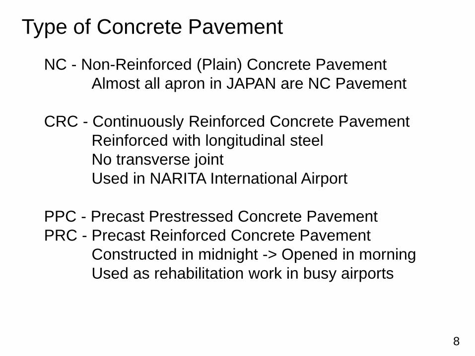
NC - Non-Reinforced (Plain) Concrete PavementAlmost all apron in JAPAN are NC Pavement
CRC - Continuously Reinforced Concrete PavementReinforced with longitudinal steelNo transverse jointUsed in NARITA International Airport
PPC - Precast Prestressed Concrete PavementPRC - Precast Reinforced Concrete Pavement
Constructed in midnight -> Opened in morningUsed as rehabilitation work in busy airports
Type of Concrete Pavement
9
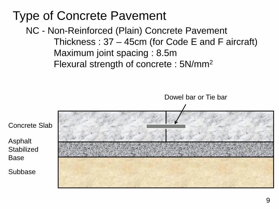
NC - Non-Reinforced (Plain) Concrete PavementThickness : 37 – 45cm (for Code E and F aircraft)Maximum joint spacing : 8.5mFlexural strength of concrete : 5N/mm2
Type of Concrete Pavement
Dowel bar or Tie bar
Concrete Slab
AsphaltStabilizedBase
Subbase
10
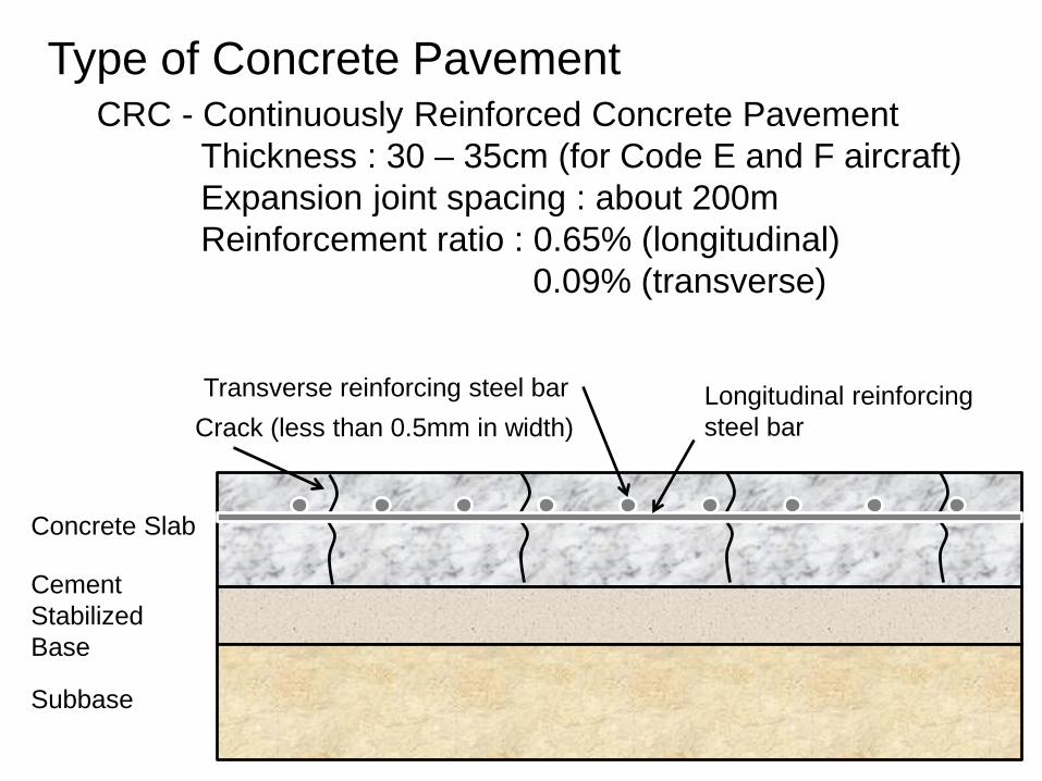
CRC - Continuously Reinforced Concrete PavementThickness : 30 – 35cm (for Code E and F aircraft)Expansion joint spacing : about 200mReinforcement ratio : 0.65% (longitudinal)
0.09% (transverse)
Type of Concrete Pavement
Concrete Slab
CementStabilizedBase
Subbase
Longitudinal reinforcingsteel barCrack (less than 0.5mm in width)
Transverse reinforcing steel bar
11
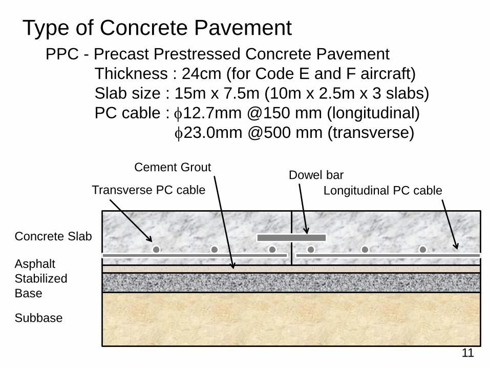
PPC - Precast Prestressed Concrete PavementThickness : 24cm (for Code E and F aircraft)Slab size : 15m x 7.5m (10m x 2.5m x 3 slabs)PC cable : φ12.7mm @150 mm (longitudinal)
φ23.0mm @500 mm (transverse)
Type of Concrete Pavement
Concrete Slab
AsphaltStabilizedBase
Subbase
Longitudinal PC cableTransverse PC cable
Cement Grout Dowel bar
12
PPC Lift-Up
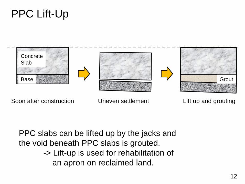
Uneven settlement Lift up and grouting
PPC slabs can be lifted up by the jacks and the void beneath PPC slabs is grouted.
-> Lift-up is used for rehabilitation of an apron on reclaimed land.
Soon after construction
ConcreteSlab
Base Grout
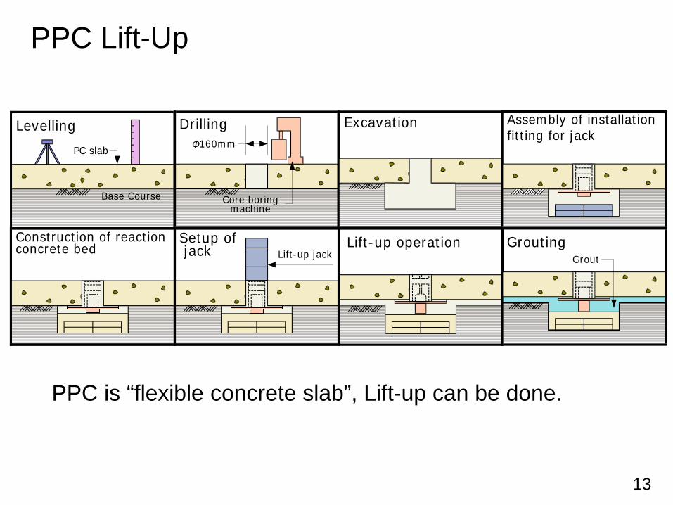
13
PC slab
Base Course
Levelling160mm
Drilling
Core boringmachine
Excavation Assembly of installationfitting for jack
Lift-up jackSetup of jack
Construction of reactionconcrete bed Lift-up operation
GroutGrouting
Φ
PPC Lift-Up
PPC is “flexible concrete slab”, Lift-up can be done.
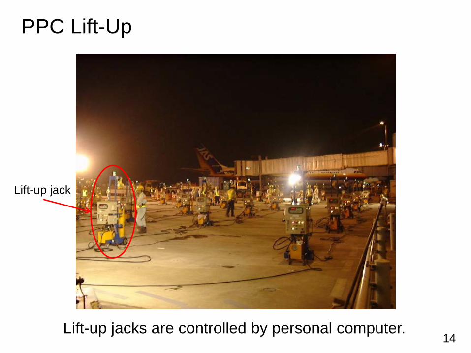
14Lift-up jacks are controlled by personal computer.
PPC Lift-Up
Lift-up jack
15
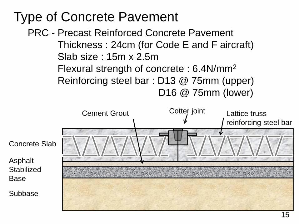
PRC - Precast Reinforced Concrete PavementThickness : 24cm (for Code E and F aircraft)Slab size : 15m x 2.5mFlexural strength of concrete : 6.4N/mm2
Reinforcing steel bar : D13 @ 75mm (upper)D16 @ 75mm (lower)
Type of Concrete Pavement
Concrete Slab
AsphaltStabilizedBase
Subbase
Lattice trussreinforcing steel bar
Cement Grout Cotter joint
16
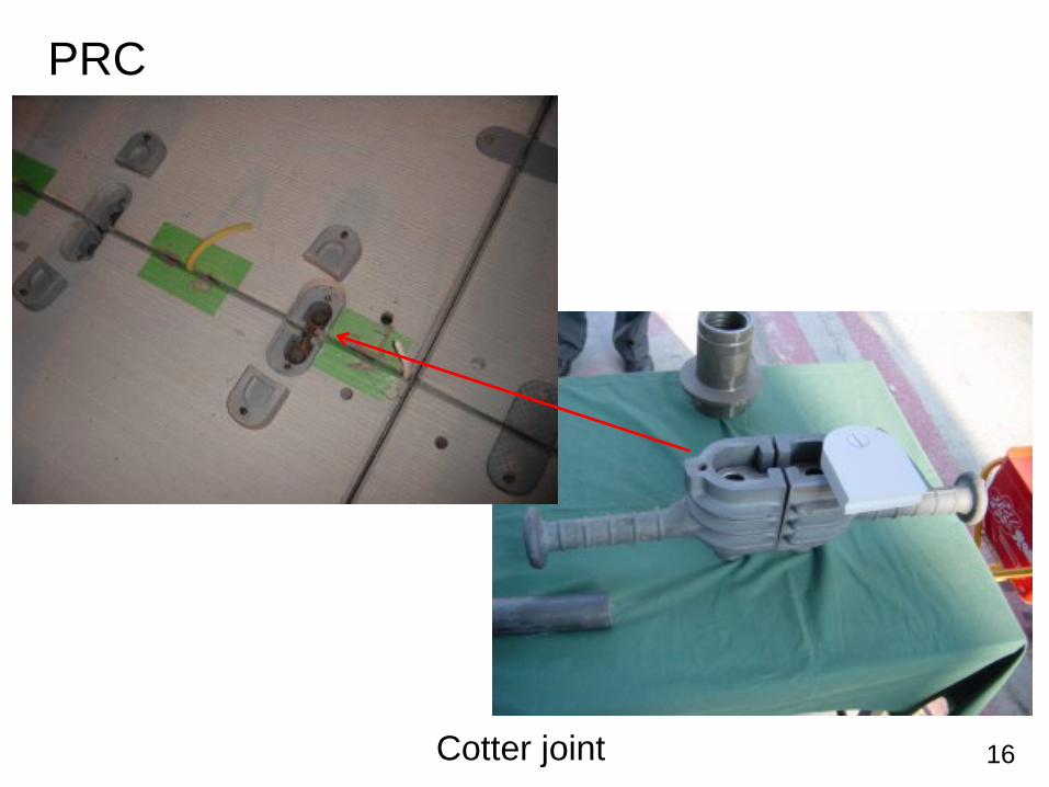
PRC
Cotter joint
17
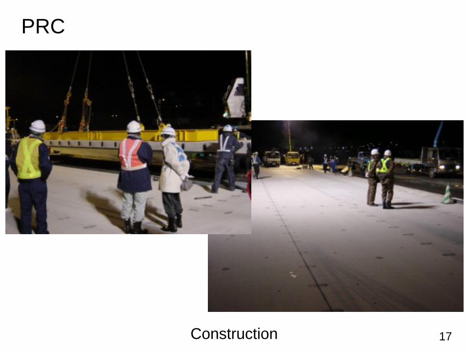
PRC
Construction
18
Design of Concrete Pavement
19
Empirical Design Method (till 2008)Slab thickness is designed based on loading stress.σ < f / a
σ : loading stress at bottom of slab due to aircraft loadf : design flexural strength of concretea : safety factor
(=1.7 to 2.2, depending on traffic volume)
Mechanistic-Empirical Design Method (after 2008)Slab thickness is designed based on fatigue degreedue to loading stress and thermal stress.
FD : fatigue degree at bottom of slab= Σ(Nd / Nf)
Nd : design number of load repetitionNf : number of failure
Design of NC Pavement
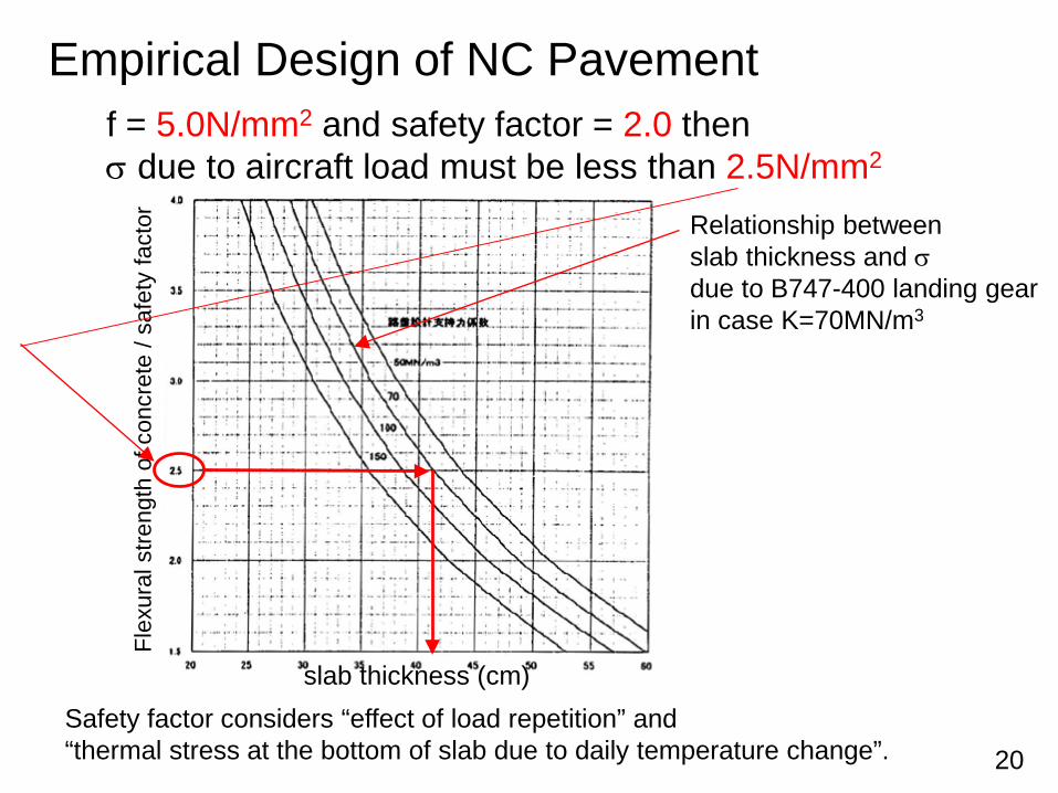
20Safety factor considers “effect of load repetition” and “thermal stress at the bottom of slab due to daily temperature change”.
Empirical Design of NC Pavementf = 5.0N/mm2 and safety factor = 2.0 thenσ due to aircraft load must be less than 2.5N/mm2
Relationship betweenslab thickness and σdue to B747-400 landing gearin case K=70MN/m3
Flex
ural
stre
ngth
of c
oncr
ete
/ saf
ety
fact
or
slab thickness (cm)
21
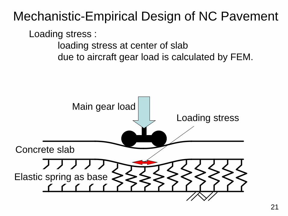
Mechanistic-Empirical Design of NC PavementLoading stress :
loading stress at center of slab due to aircraft gear load is calculated by FEM.
Concrete slab
Elastic spring as base
Main gear loadLoading stress
22
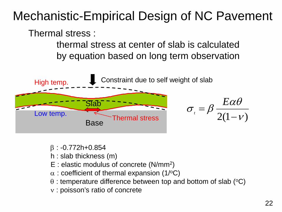
Mechanistic-Empirical Design of NC PavementThermal stress :
thermal stress at center of slab is calculatedby equation based on long term observation
)1(2 ναθβσ−
=E
t
β : -0.772h+0.854h : slab thickness (m)E : elastic modulus of concrete (N/mm2)α : coefficient of thermal expansion (1/oC)θ : temperature difference between top and bottom of slab (oC)ν : poisson’s ratio of concrete
Base
Slab
High temp.
Low temp.
Constraint due to self weight of slab
Thermal stress
23
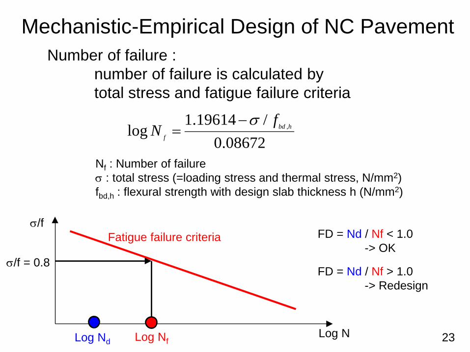
Mechanistic-Empirical Design of NC PavementNumber of failure :
number of failure is calculated bytotal stress and fatigue failure criteria
08672.0/19614.1
log ,hbd
f
fN
σ−=
Nf : Number of failureσ : total stress (=loading stress and thermal stress, N/mm2)fbd,h : flexural strength with design slab thickness h (N/mm2)
Fatigue failure criteria
Log N
σ/f
Log Nf
σ/f = 0.8
FD = Nd / Nf < 1.0-> OK
FD = Nd / Nf > 1.0-> Redesign
Log Nd
24
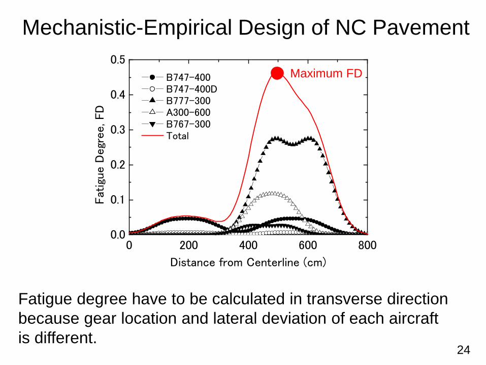
Mechanistic-Empirical Design of NC Pavement
Fatigue degree have to be calculated in transverse directionbecause gear location and lateral deviation of each aircraftis different.
0 200 400 600 8000.0
0.1
0.2
0.3
0.4
0.5
Fat
igue D
egr
ee, FD
Distance from Centerline (cm)
B747-400 B747-400D B777-300 A300-600 B767-300 Total
Maximum FD
25
Construction of Concrete Pavement
26
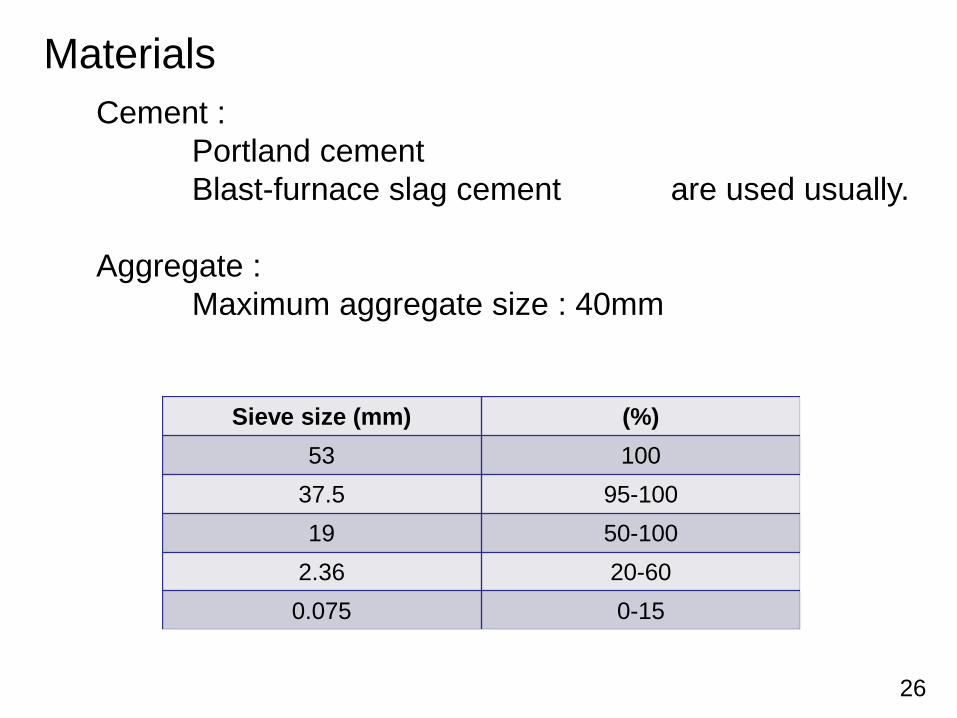
MaterialsCement :
Portland cementBlast-furnace slag cement are used usually.
Aggregate : Maximum aggregate size : 40mm
Sieve size (mm) (%)53 100
37.5 95-10019 50-100
2.36 20-600.075 0-15
27
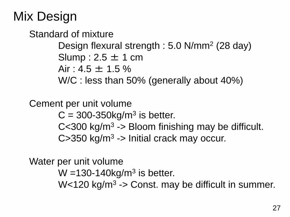
Mix DesignStandard of mixture
Design flexural strength : 5.0 N/mm2 (28 day)Slump : 2.5 ± 1 cmAir : 4.5 ± 1.5 %W/C : less than 50% (generally about 40%)
Cement per unit volumeC = 300-350kg/m3 is better.C<300 kg/m3 -> Bloom finishing may be difficult.C>350 kg/m3 -> Initial crack may occur.
Water per unit volumeW =130-140kg/m3 is better.W<120 kg/m3 -> Const. may be difficult in summer.
28
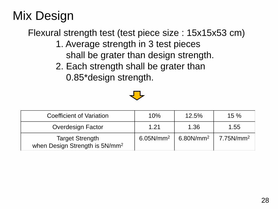
Mix DesignFlexural strength test (test piece size : 15x15x53 cm)
1. Average strength in 3 test piecesshall be grater than design strength.
2. Each strength shall be grater than0.85*design strength.
Coefficient of Variation 10% 12.5% 15 %
Overdesign Factor 1.21 1.36 1.55
Target Strengthwhen Design Strength is 5N/mm2
6.05N/mm2 6.80N/mm2 7.75N/mm2
29
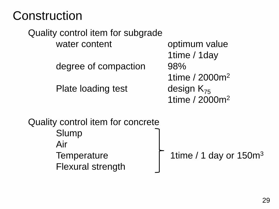
ConstructionQuality control item for subgrade
water content optimum value1time / 1day
degree of compaction 98%1time / 2000m2
Plate loading test design K751time / 2000m2
Quality control item for concreteSlumpAirTemperature 1time / 1 day or 150m3
Flexural strength
30
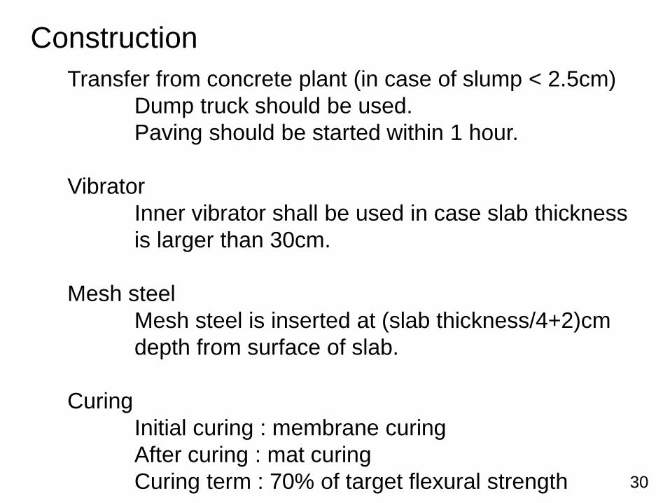
ConstructionTransfer from concrete plant (in case of slump < 2.5cm)
Dump truck should be used.Paving should be started within 1 hour.
VibratorInner vibrator shall be used in case slab thicknessis larger than 30cm.
Mesh steelMesh steel is inserted at (slab thickness/4+2)cmdepth from surface of slab.
CuringInitial curing : membrane curingAfter curing : mat curingCuring term : 70% of target flexural strength
31
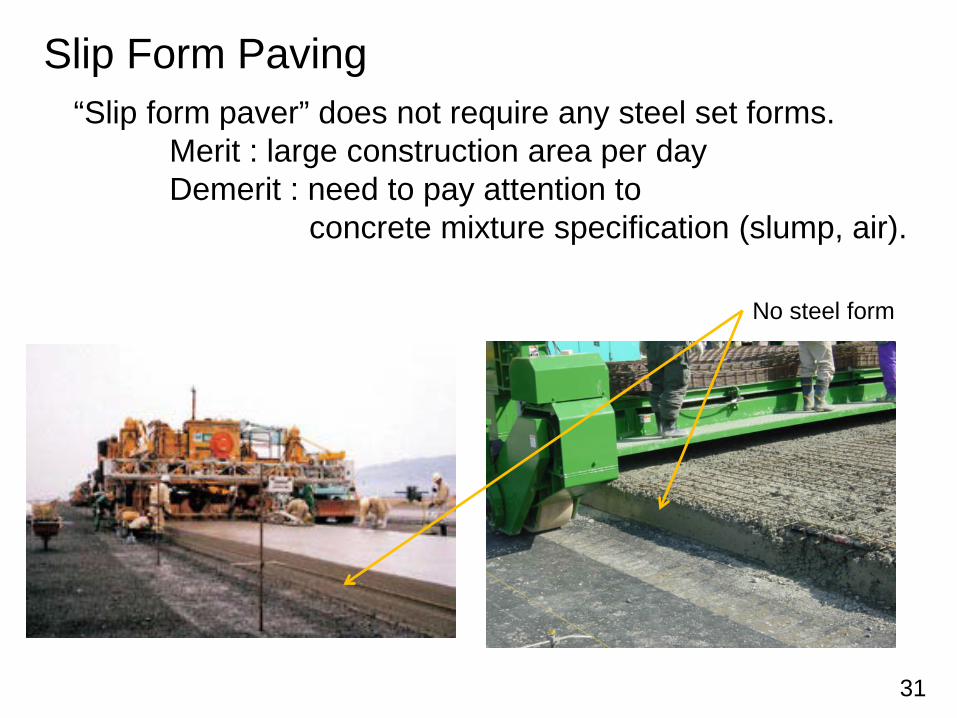
Slip Form Paving“Slip form paver” does not require any steel set forms.
Merit : large construction area per dayDemerit : need to pay attention to
concrete mixture specification (slump, air).
No steel form
32
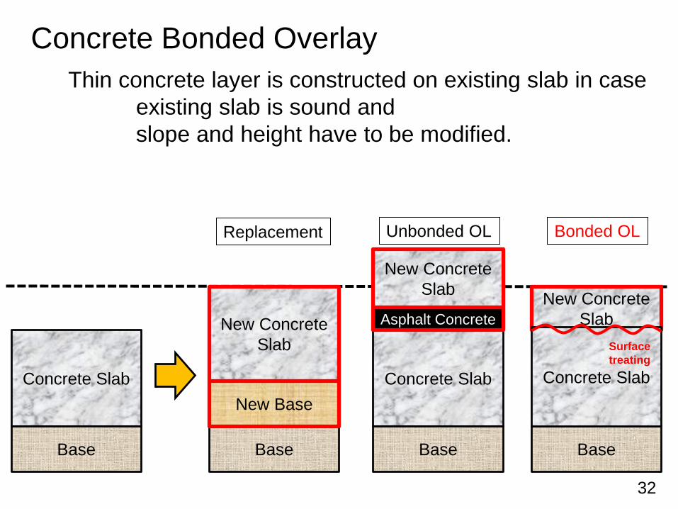
Concrete Bonded OverlayThin concrete layer is constructed on existing slab in case
existing slab is sound andslope and height have to be modified.
Concrete Slab
Base
New ConcreteSlab
Base
Concrete Slab
Base Base
Replacement Unbonded OL Bonded OL
New Base
Asphalt Concrete
New ConcreteSlab New Concrete
Slab
Concrete Slab
Surfacetreating
33
Concrete Bonded Overlay
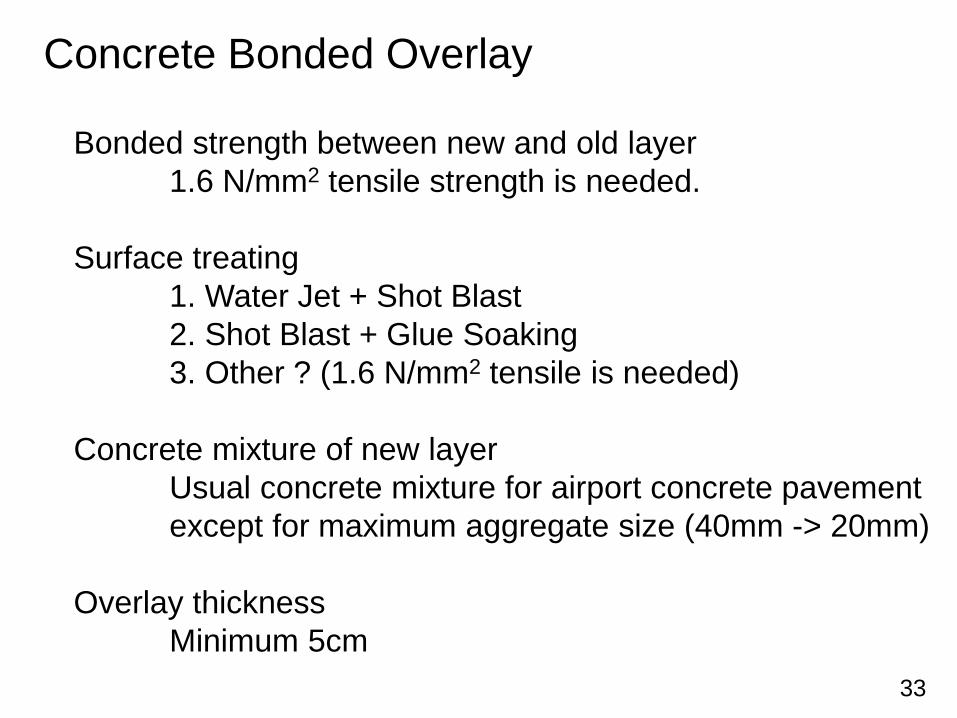
Bonded strength between new and old layer1.6 N/mm2 tensile strength is needed.
Surface treating1. Water Jet + Shot Blast2. Shot Blast + Glue Soaking3. Other ? (1.6 N/mm2 tensile is needed)
Concrete mixture of new layerUsual concrete mixture for airport concrete pavementexcept for maximum aggregate size (40mm -> 20mm)
Overlay thicknessMinimum 5cm
34
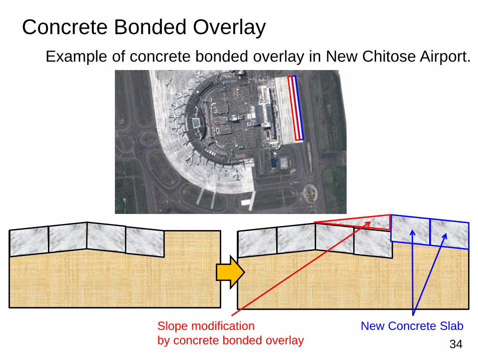
Concrete Bonded OverlayExample of concrete bonded overlay in New Chitose Airport.
New Concrete SlabSlope modificationby concrete bonded overlay

35
Concrete Bonded Overlay
After WJ Before WJ
Surface treating by Water Jet (WJ)
36
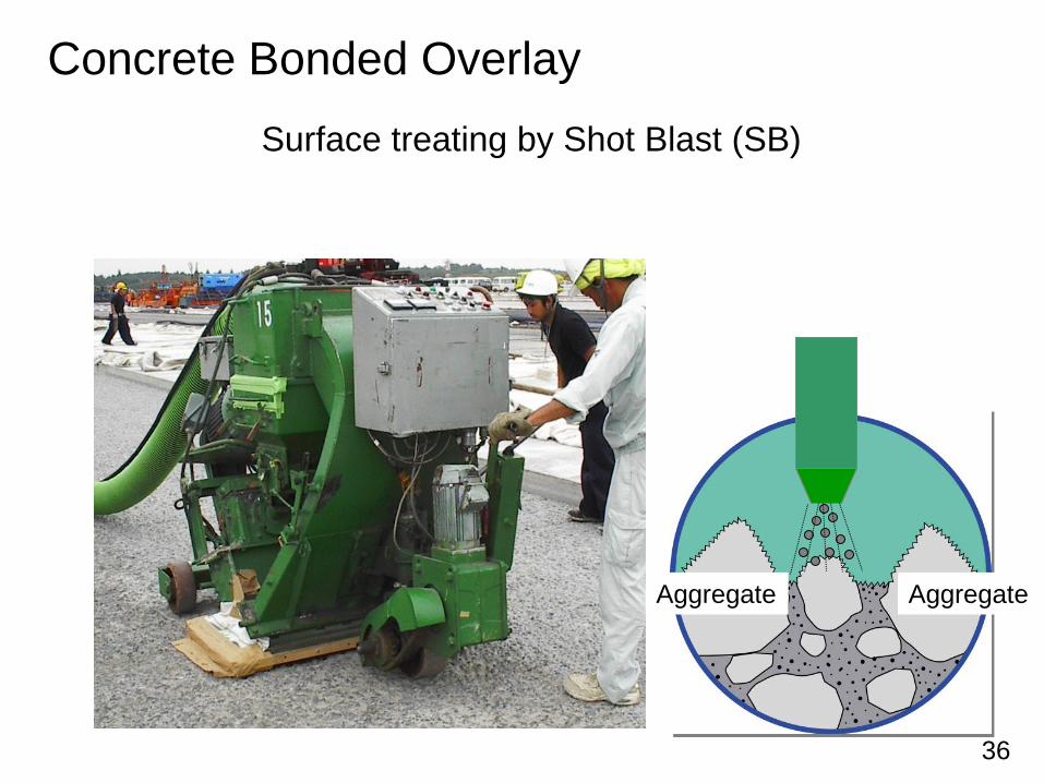
Concrete Bonded OverlaySurface treating by Shot Blast (SB)
Aggregate Aggregate
37
Concrete Bonded Overlay
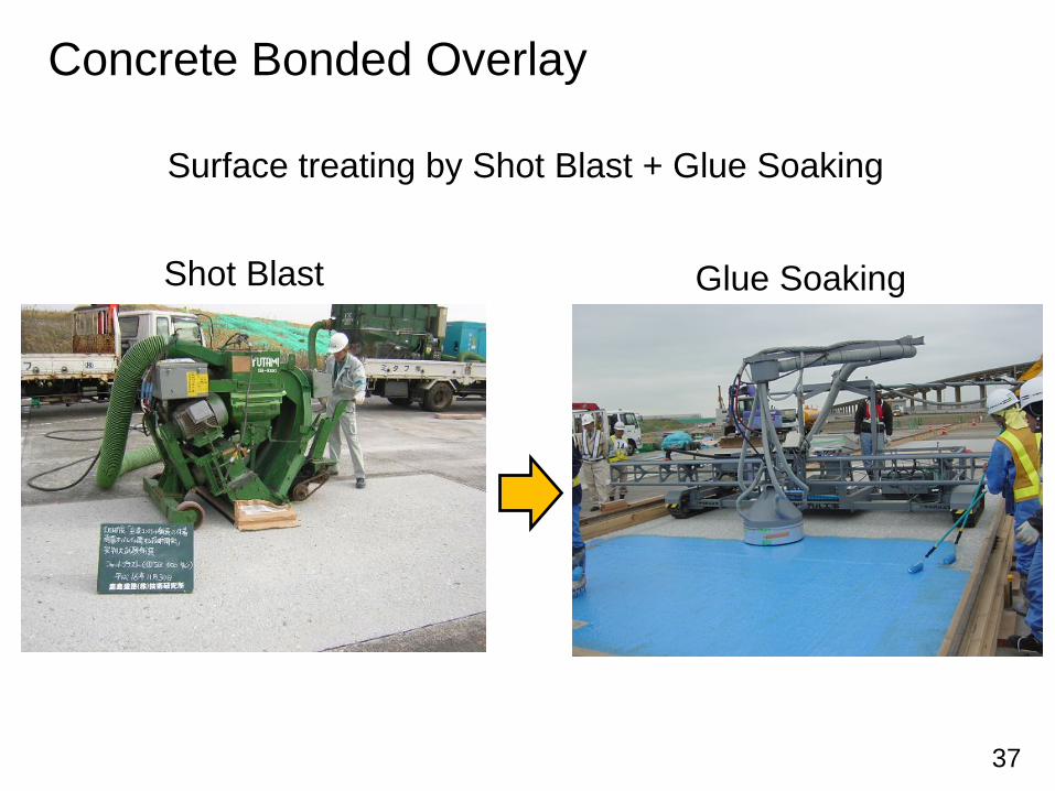
Surface treating by Shot Blast + Glue Soaking
Shot Blast Glue Soaking