Embed Size (px)
Citation preview
June 2007Amund Skavhaug, ITK
Master of Science in Engineering CyberneticsSubmission date:Supervisor:
Norwegian University of Science and TechnologyDepartment of Engineering Cybernetics
Developing Embedded Control SystemPlatform using Atmel AVR32 ProcessorUsing Rapid Prototyping with Matlab Real-Time Workshop
Øyvind Netland

Problem Description
The goal of this master thesis is to use the new AVR32 processor architecture together with adeveloped I/O-card in a control system. The control system should be able use Matlab Real-TimeWorkshop generated code for rapid prototyping.
The assignment consists of:- Learn how the AVR32 architecture and the STK1000 card works.- Install developing- and debugging tools for the AVR32 architecture on a Linux workstation.- Make a basic Linux system for the STK1000 card.- Implement timers for controlling the periodic Matlab execution, and test how accurate these are.- Design and implement a I/O-card using an 8-bit AVR microcontroller.- Design the interface between the I/O-card and AVR32, and implement a driver the AVR32 can useto control the I/O-card.- Find out how to compile and run Matlab Real-Time Workshop generated code under Linux on theAVR32 architecture.- Make Matlab Simulink blocks for the I/O-card.- Make it easy to use Matlab Real-Time Workshop code on AVR32 for rapid prototyping.- Test and identify the efficiency and limits of the system.- Make a control system platform with AVR32, that users can build their control system on.- Make a user manual for the platform that contain the information a user needs to use it, so it canbe used with minimal effort.
Assignment given: 08. January 2007Supervisor: Amund Skavhaug, ITK


Preface
This thesis has been very interesting, and a worthy end of my time at NTNU. It has been aprivilege to work with a new processor architecture, and try to do something that nobodyas far as I know have tried before. I would like to thank Amund Skavhaug, my supervisor,and Haavard Skinnemoen from Atmel Norway. Both of them have been helpful wheneverI have needed some guidance.

Abstract
AVR32 is a new processor architecture made by Atmel Norway, and in this thesis it hasbeen used to make a control system platform. The hardware used in this platform is theSTK1000, an AVR32 development board and an I/O-card. The I/O-card were developedas a part of the thesis. Software for the platform consists of I/O-card firmware, Linuxdevice driver for the I/O-card and user mode drivers.
The platform supports usage of Matlab Real-Time Workshop as a rapid prototyping tool,that generates code from graphical visualization of mathematical models. S-functions werecreated so Matlab Real-Time Workshop can control the I/O-card.
The control system platform is documented in an user manual. This manual describeshow to install development tools for the platform on a Linux or Windows computer, andhow to use the it.

Contents
1 Introduction 1
2 Background 32.1 Embedded Control System . . . . . . . . . . . . . . . . . . . . . . . . . . . . 3
2.1.1 Real-time Constraints . . . . . . . . . . . . . . . . . . . . . . . . . . 32.1.2 Input/Output . . . . . . . . . . . . . . . . . . . . . . . . . . . . . . . 3
2.2 Atmel AVR32 Architecture . . . . . . . . . . . . . . . . . . . . . . . . . . . 42.2.1 STK1000 . . . . . . . . . . . . . . . . . . . . . . . . . . . . . . . . . 42.2.2 AT32AP7000 . . . . . . . . . . . . . . . . . . . . . . . . . . . . . . . 4
2.3 Linux . . . . . . . . . . . . . . . . . . . . . . . . . . . . . . . . . . . . . . . 42.3.1 Linux Control Systems . . . . . . . . . . . . . . . . . . . . . . . . . . 52.3.2 Kernel Mode and User Mode . . . . . . . . . . . . . . . . . . . . . . 62.3.3 Linux Device Driver . . . . . . . . . . . . . . . . . . . . . . . . . . . 62.3.4 AVR32 Linux . . . . . . . . . . . . . . . . . . . . . . . . . . . . . . . 62.3.5 AVR32 Linux development tools . . . . . . . . . . . . . . . . . . . . 7
2.4 Rapid Prototyping . . . . . . . . . . . . . . . . . . . . . . . . . . . . . . . . 72.4.1 Rapid Prototyping Control Systems . . . . . . . . . . . . . . . . . . 8
3 AVR32 Linux on STK1000 93.1 Development Tools . . . . . . . . . . . . . . . . . . . . . . . . . . . . . . . . 9
3.1.1 Compiling Development Tools from Source . . . . . . . . . . . . . . 93.2 AVR32 Linux Kernel Versions . . . . . . . . . . . . . . . . . . . . . . . . . . 103.3 Configure booting over Network . . . . . . . . . . . . . . . . . . . . . . . . . 10
3.3.1 Workstation Configuration . . . . . . . . . . . . . . . . . . . . . . . 103.3.2 Configure U-Boot . . . . . . . . . . . . . . . . . . . . . . . . . . . . . 11
4 Preliminary tests of AVR32 134.1 Floating-point and Fixed-point operation Test . . . . . . . . . . . . . . . . . 13
4.1.1 Code . . . . . . . . . . . . . . . . . . . . . . . . . . . . . . . . . . . . 134.1.2 Result . . . . . . . . . . . . . . . . . . . . . . . . . . . . . . . . . . . 14
4.2 Timer precision Test . . . . . . . . . . . . . . . . . . . . . . . . . . . . . . . 144.2.1 Code . . . . . . . . . . . . . . . . . . . . . . . . . . . . . . . . . . . . 154.2.2 Result . . . . . . . . . . . . . . . . . . . . . . . . . . . . . . . . . . . 15
4.3 Test of Matlab Real-Time Workshop Generated Code . . . . . . . . . . . . 164.4 Preliminary Test Conclusion . . . . . . . . . . . . . . . . . . . . . . . . . . . 16
5 Preliminary tests of I/O-card 19
i
5.1 AVR Microcontroller . . . . . . . . . . . . . . . . . . . . . . . . . . . . . . . 195.1.1 ATmega128 . . . . . . . . . . . . . . . . . . . . . . . . . . . . . . . . 195.1.2 STK500/501 . . . . . . . . . . . . . . . . . . . . . . . . . . . . . . . 20
5.2 Analog input . . . . . . . . . . . . . . . . . . . . . . . . . . . . . . . . . . . 205.2.1 Test of ATmega128 ADC . . . . . . . . . . . . . . . . . . . . . . . . 20
5.3 Analog Output . . . . . . . . . . . . . . . . . . . . . . . . . . . . . . . . . . 215.3.1 Generating Analog Signal from PWM . . . . . . . . . . . . . . . . . 215.3.2 Quality of Analog Signal . . . . . . . . . . . . . . . . . . . . . . . . . 215.3.3 Time constant (RC) . . . . . . . . . . . . . . . . . . . . . . . . . . . 235.3.4 Frequency and Resolution . . . . . . . . . . . . . . . . . . . . . . . . 245.3.5 Order of low-pass Filter . . . . . . . . . . . . . . . . . . . . . . . . . 245.3.6 Test of ATmega128 PWM as DAC . . . . . . . . . . . . . . . . . . . 24
5.4 SPI . . . . . . . . . . . . . . . . . . . . . . . . . . . . . . . . . . . . . . . . . 265.4.1 SPI bus . . . . . . . . . . . . . . . . . . . . . . . . . . . . . . . . . . 265.4.2 SPI transfer . . . . . . . . . . . . . . . . . . . . . . . . . . . . . . . . 27
5.5 Test of SPI communication between AVR32 and ATmega128 . . . . . . . . 275.5.1 Hardware setup . . . . . . . . . . . . . . . . . . . . . . . . . . . . . . 285.5.2 AVR32 as SPI master . . . . . . . . . . . . . . . . . . . . . . . . . . 285.5.3 ATmega128 as SPI slave . . . . . . . . . . . . . . . . . . . . . . . . . 295.5.4 Result . . . . . . . . . . . . . . . . . . . . . . . . . . . . . . . . . . . 30
6 Prototype I/O-card 316.1 PCB Software . . . . . . . . . . . . . . . . . . . . . . . . . . . . . . . . . . . 316.2 Features . . . . . . . . . . . . . . . . . . . . . . . . . . . . . . . . . . . . . . 316.3 Components . . . . . . . . . . . . . . . . . . . . . . . . . . . . . . . . . . . . 326.4 Schematic . . . . . . . . . . . . . . . . . . . . . . . . . . . . . . . . . . . . . 32
6.4.1 Power Circuit . . . . . . . . . . . . . . . . . . . . . . . . . . . . . . . 336.4.2 Reset, Crystal and Analog Supply Circuit . . . . . . . . . . . . . . . 346.4.3 JTAG header and Analog Input Connectors . . . . . . . . . . . . . . 346.4.4 RS-232 circuit and Digital Output Connectors . . . . . . . . . . . . 356.4.5 STK1000 headers and Digital Input Connectors . . . . . . . . . . . . 356.4.6 Decoupling Capacitors and VCC/GND Connectors . . . . . . . . . . 356.4.7 Analog Output Circuit . . . . . . . . . . . . . . . . . . . . . . . . . . 37
6.5 Layout . . . . . . . . . . . . . . . . . . . . . . . . . . . . . . . . . . . . . . . 386.6 Assembly and test . . . . . . . . . . . . . . . . . . . . . . . . . . . . . . . . 40
6.6.1 Power Regulator Circuit . . . . . . . . . . . . . . . . . . . . . . . . . 406.6.2 ATmega128 and JTAG Interface . . . . . . . . . . . . . . . . . . . . 406.6.3 Crystal Circuit . . . . . . . . . . . . . . . . . . . . . . . . . . . . . . 406.6.4 RS-232 and Reset Circuits . . . . . . . . . . . . . . . . . . . . . . . . 416.6.5 Headers for STK1000 and debugging . . . . . . . . . . . . . . . . . . 416.6.6 ADC Supply Filter . . . . . . . . . . . . . . . . . . . . . . . . . . . . 416.6.7 Analog Output Circuit . . . . . . . . . . . . . . . . . . . . . . . . . . 42
6.7 Errors in Schematic . . . . . . . . . . . . . . . . . . . . . . . . . . . . . . . 42
7 Design of I/O-card Software 437.1 Communication Protocol . . . . . . . . . . . . . . . . . . . . . . . . . . . . . 43
7.1.1 Commands . . . . . . . . . . . . . . . . . . . . . . . . . . . . . . . . 437.1.2 Message Structure . . . . . . . . . . . . . . . . . . . . . . . . . . . . 44
ii
7.1.3 Acknowledgments . . . . . . . . . . . . . . . . . . . . . . . . . . . . 467.1.4 SPI codes . . . . . . . . . . . . . . . . . . . . . . . . . . . . . . . . . 46
7.2 ATmega128 Firmware . . . . . . . . . . . . . . . . . . . . . . . . . . . . . . 487.2.1 SPI commands . . . . . . . . . . . . . . . . . . . . . . . . . . . . . . 487.2.2 Analog Input . . . . . . . . . . . . . . . . . . . . . . . . . . . . . . . 507.2.3 Timeout . . . . . . . . . . . . . . . . . . . . . . . . . . . . . . . . . . 51
7.3 Device Driver . . . . . . . . . . . . . . . . . . . . . . . . . . . . . . . . . . . 517.3.1 Device Nodes . . . . . . . . . . . . . . . . . . . . . . . . . . . . . . . 527.3.2 Master send Data . . . . . . . . . . . . . . . . . . . . . . . . . . . . 527.3.3 Request Data from Slave . . . . . . . . . . . . . . . . . . . . . . . . 54
7.4 User Mode Driver . . . . . . . . . . . . . . . . . . . . . . . . . . . . . . . . . 557.5 Threaded User Mode Driver . . . . . . . . . . . . . . . . . . . . . . . . . . . 55
7.5.1 Threaded Analog Input . . . . . . . . . . . . . . . . . . . . . . . . . 557.5.2 Threaded Analog Output . . . . . . . . . . . . . . . . . . . . . . . . 56
8 Implementation of I/O-card Software 578.1 ATmega128 Firmware . . . . . . . . . . . . . . . . . . . . . . . . . . . . . . 57
8.1.1 am128main . . . . . . . . . . . . . . . . . . . . . . . . . . . . . . . . 578.1.2 am128io . . . . . . . . . . . . . . . . . . . . . . . . . . . . . . . . . . 598.1.3 am128slaveSpi . . . . . . . . . . . . . . . . . . . . . . . . . . . . . . 618.1.4 am128ADC . . . . . . . . . . . . . . . . . . . . . . . . . . . . . . . . 628.1.5 am128pwm . . . . . . . . . . . . . . . . . . . . . . . . . . . . . . . . 638.1.6 am128uart . . . . . . . . . . . . . . . . . . . . . . . . . . . . . . . . 63
8.2 Device driver . . . . . . . . . . . . . . . . . . . . . . . . . . . . . . . . . . . 648.2.1 Init and Exit Functions . . . . . . . . . . . . . . . . . . . . . . . . . 648.2.2 Major and Minor Numbers . . . . . . . . . . . . . . . . . . . . . . . 648.2.3 Char Device registration . . . . . . . . . . . . . . . . . . . . . . . . . 658.2.4 SPI device and driver . . . . . . . . . . . . . . . . . . . . . . . . . . 668.2.5 Changes in Linux Kernel Source Code . . . . . . . . . . . . . . . . . 668.2.6 avr32io . . . . . . . . . . . . . . . . . . . . . . . . . . . . . . . . . . 678.2.7 avr32io Cmd . . . . . . . . . . . . . . . . . . . . . . . . . . . . . . . 698.2.8 avr32io SPI . . . . . . . . . . . . . . . . . . . . . . . . . . . . . . . . 71
8.3 Linux Kernel Patch . . . . . . . . . . . . . . . . . . . . . . . . . . . . . . . . 728.4 User Mode Driver . . . . . . . . . . . . . . . . . . . . . . . . . . . . . . . . . 728.5 Threaded User Mode Driver . . . . . . . . . . . . . . . . . . . . . . . . . . . 74
8.5.1 Threaded Analog Input . . . . . . . . . . . . . . . . . . . . . . . . . 758.5.2 Threaded Analog Output . . . . . . . . . . . . . . . . . . . . . . . . 75
9 Testing with prototype card 779.1 Test of SPI communication . . . . . . . . . . . . . . . . . . . . . . . . . . . 77
9.1.1 Frequency of SPI connection . . . . . . . . . . . . . . . . . . . . . . 779.1.2 Time used on SPI transfers . . . . . . . . . . . . . . . . . . . . . . . 779.1.3 Time used on Commands . . . . . . . . . . . . . . . . . . . . . . . . 789.1.4 Reliability . . . . . . . . . . . . . . . . . . . . . . . . . . . . . . . . . 789.1.5 Reliability when using Timeout . . . . . . . . . . . . . . . . . . . . . 79
9.2 Test of Analog Output . . . . . . . . . . . . . . . . . . . . . . . . . . . . . . 799.2.1 Simulation . . . . . . . . . . . . . . . . . . . . . . . . . . . . . . . . 799.2.2 Testing Filters . . . . . . . . . . . . . . . . . . . . . . . . . . . . . . 79
iii
9.2.3 Operational Amplifiers . . . . . . . . . . . . . . . . . . . . . . . . . . 809.3 Test of Analog Input . . . . . . . . . . . . . . . . . . . . . . . . . . . . . . . 81
9.3.1 Precision of Analog Input . . . . . . . . . . . . . . . . . . . . . . . . 819.3.2 Buffering and Interrupt mode . . . . . . . . . . . . . . . . . . . . . . 81
10 Final version of I/O-card 8310.1 Changes from Prototype . . . . . . . . . . . . . . . . . . . . . . . . . . . . . 8310.2 Schematic . . . . . . . . . . . . . . . . . . . . . . . . . . . . . . . . . . . . . 8410.3 Layout . . . . . . . . . . . . . . . . . . . . . . . . . . . . . . . . . . . . . . . 8410.4 Problems with Analog Output . . . . . . . . . . . . . . . . . . . . . . . . . 84
11 Matlab Real-Time Workshop 8711.1 Matlab Real-Time Workshop . . . . . . . . . . . . . . . . . . . . . . . . . . 87
11.1.1 Target Language Compiler (TLC) . . . . . . . . . . . . . . . . . . . 8711.1.2 S-functions . . . . . . . . . . . . . . . . . . . . . . . . . . . . . . . . 88
11.2 Making a AVR32 Real-Time Target . . . . . . . . . . . . . . . . . . . . . . 8811.2.1 avr32.tlc . . . . . . . . . . . . . . . . . . . . . . . . . . . . . . . . . . 8911.2.2 avr32.tmf . . . . . . . . . . . . . . . . . . . . . . . . . . . . . . . . . 8911.2.3 avr32main.c . . . . . . . . . . . . . . . . . . . . . . . . . . . . . . . . 90
11.3 S-functions for I/O-card . . . . . . . . . . . . . . . . . . . . . . . . . . . . . 9111.3.1 Simulink S-function File . . . . . . . . . . . . . . . . . . . . . . . . . 9211.3.2 Target Block Files . . . . . . . . . . . . . . . . . . . . . . . . . . . . 93
11.4 Results . . . . . . . . . . . . . . . . . . . . . . . . . . . . . . . . . . . . . . . 9311.4.1 Results of Analog Test . . . . . . . . . . . . . . . . . . . . . . . . . . 9311.4.2 Results of Digital Test . . . . . . . . . . . . . . . . . . . . . . . . . . 95
12 User manual for AVR32 I/O 9712.1 Installing . . . . . . . . . . . . . . . . . . . . . . . . . . . . . . . . . . . . . 97
12.1.1 Install AVR32 tool-chain . . . . . . . . . . . . . . . . . . . . . . . . 9712.1.2 Compile Linux kernel with AVR32 I/O-card support . . . . . . . . . 9812.1.3 Install AVR32 support in Matlab . . . . . . . . . . . . . . . . . . . . 98
12.2 AVR32 I/O-card . . . . . . . . . . . . . . . . . . . . . . . . . . . . . . . . . 9912.2.1 Hardware description . . . . . . . . . . . . . . . . . . . . . . . . . . 9912.2.2 Connecting I/O-card . . . . . . . . . . . . . . . . . . . . . . . . . . . 10112.2.3 Analog Input . . . . . . . . . . . . . . . . . . . . . . . . . . . . . . . 10112.2.4 Analog Output . . . . . . . . . . . . . . . . . . . . . . . . . . . . . . 101
12.3 Rapid prototyping with Matlab Real-Time Workshop . . . . . . . . . . . . 10212.3.1 AVR32 System Target . . . . . . . . . . . . . . . . . . . . . . . . . . 10212.3.2 S-functions for I/O-card . . . . . . . . . . . . . . . . . . . . . . . . . 102
13 Discussion 10513.1 AVR32 Linux . . . . . . . . . . . . . . . . . . . . . . . . . . . . . . . . . . . 10513.2 I/O-card . . . . . . . . . . . . . . . . . . . . . . . . . . . . . . . . . . . . . . 10513.3 I/O-card Communication and Drivers . . . . . . . . . . . . . . . . . . . . . 10613.4 Matlab Real-Time Workshop . . . . . . . . . . . . . . . . . . . . . . . . . . 107
14 Conclusion 109
15 Further Work 111
iv
A Digital appendix 113
B Schematics 114B.1 Schematic for protoype card . . . . . . . . . . . . . . . . . . . . . . . . . . . 114B.2 Schematic for final card . . . . . . . . . . . . . . . . . . . . . . . . . . . . . 114
C Code 117C.1 ATmega128 . . . . . . . . . . . . . . . . . . . . . . . . . . . . . . . . . . . . 117
C.1.1 Makefile . . . . . . . . . . . . . . . . . . . . . . . . . . . . . . . . . . 117C.1.2 am128main.c . . . . . . . . . . . . . . . . . . . . . . . . . . . . . . . 117C.1.3 am128io.c . . . . . . . . . . . . . . . . . . . . . . . . . . . . . . . . . 118C.1.4 am128spiSlave.c . . . . . . . . . . . . . . . . . . . . . . . . . . . . . 122C.1.5 am128adc.c . . . . . . . . . . . . . . . . . . . . . . . . . . . . . . . . 122C.1.6 am128pwm.c . . . . . . . . . . . . . . . . . . . . . . . . . . . . . . . 124C.1.7 am128uart.c . . . . . . . . . . . . . . . . . . . . . . . . . . . . . . . . 126
C.2 Kernel module . . . . . . . . . . . . . . . . . . . . . . . . . . . . . . . . . . 128C.2.1 Makefile . . . . . . . . . . . . . . . . . . . . . . . . . . . . . . . . . . 128C.2.2 avr32ioc . . . . . . . . . . . . . . . . . . . . . . . . . . . . . . . . . . 128C.2.3 avr32io Cmd.c . . . . . . . . . . . . . . . . . . . . . . . . . . . . . . 131C.2.4 avr32io SPI.c . . . . . . . . . . . . . . . . . . . . . . . . . . . . . . . 135
C.3 User Mode . . . . . . . . . . . . . . . . . . . . . . . . . . . . . . . . . . . . 136C.3.1 avr32io driver.c . . . . . . . . . . . . . . . . . . . . . . . . . . . . . . 136C.3.2 avr32io threads.c . . . . . . . . . . . . . . . . . . . . . . . . . . . . . 139C.3.3 periodictask.h . . . . . . . . . . . . . . . . . . . . . . . . . . . . . . . 141C.3.4 periodictask.c . . . . . . . . . . . . . . . . . . . . . . . . . . . . . . . 142C.3.5 stopwatch.h . . . . . . . . . . . . . . . . . . . . . . . . . . . . . . . . 143C.3.6 stopwatch.c . . . . . . . . . . . . . . . . . . . . . . . . . . . . . . . . 144
C.4 Matlab S-functions . . . . . . . . . . . . . . . . . . . . . . . . . . . . . . . . 144C.4.1 Analog input TLC . . . . . . . . . . . . . . . . . . . . . . . . . . . . 144C.4.2 Analog output TLC . . . . . . . . . . . . . . . . . . . . . . . . . . . 145C.4.3 Digital input TLC . . . . . . . . . . . . . . . . . . . . . . . . . . . . 145C.4.4 Digital output TLC . . . . . . . . . . . . . . . . . . . . . . . . . . . 146
v

vi
Chapter 1
Introduction
Today, computer electronics are found almost everywhere. Many ordinary items containsmall embedded computers and new cars have computer controlled breaks, fuel injectionand stability control. A computer system that controls a physical system is called a controlsystem, and control systems are continuously getting more complex and smaller in physicalsize.
In 2006, Atmel Norway released a new processor architecture called AVR32. This processorarchitecture is designed for use in embedded systems, specially small system with low powerconsumption. Small physical size and low power consumption are very important for manycontrol systems, specially if the system is battery powered.
The main goal of this thesis was to make use of this new architecture to make a platformfor control systems. This will use an AVR32 version of Linux as an operating system,since Linux is an operating system that is free, open source and suited for embeddeddevelopment. Atmel Norway has ported the Linux kernel and many tools to the AVR32architecture, so it’s a natural choice.
A control system has to be able to observe and control the environment. To give theAVR32 this capability, an Input/Output-card has been developed. This card makes theAVR32 able to send and receive analog voltage signal from sensors and actuators, and arethe AVR32s extension into the physical world.
To make development of control systems easier on the platform, Matlab Real-Time Work-shop was adapted so it can be used as a rapid prototyping tool. This means that codecan be generated from Matlab Simulink models, and it runs on the control system. Thismakes it easy to implement different control systems through the graphical interface ofSimulink. The I/O-card can be used in Real-Time Workshop by using the developedSimulink S-function blocks.
To make it easier to use the control system platform, an user manual was written. Thiscontain information about how to install the needed tools and use the control systemplatform from a Linux distribution or Windows. This is an important part of the thesis,since one of the goals were to make an user-friendly product. The manual should giveenough information to use the control system platform. To develop the system further,this report should be read.
2 CHAPTER 1. INTRODUCTION
The chapters in this report are as follows:
Chapter 2 BackgroundThis chapter describes some of the technologies and concepts behind the thesis.
Chapter 3 AVR32 Linux on STK1000This chapter Describes how to install and use AVR32 Linux on STK1000.
Chapter 4 Preliminary tests of AVR32This chapter performs tests to find out the capabilities of the STK1000 developmentboard and the AVR32 processor architecture.
Chapter 5 Preliminary tests of I/O-cardThis chapter performs tests to find out if correct solutions have been chosen for theI/O-card.
Chapter 6 Prototype I/O-cardThis chapter describes the design and production of the prototype I/O-card.
Chapter 7 Design of I/O-card softwareThis chapter describes the design of the I/O-card drivers and firmware.
Chapter 8 Implementation of I/O-card softwareThis chapter describes the implementation of the I/O-card drivers and firmware.
Chapter 9 Testing with prototype cardThis chapter testing the prototype card with the I/O-card drivers and firmware.
Chapter 10 Final version of I/O-cardThis chapter describes the design and production of the final version of the I/O-card.
Chapter 11 Matlab Real-Time WorkshopThis chapter adapts Matlab Real-Time Workshop to be used as a rapid prototypingtool for the control system platform.
Chapter 12 User manualThis chapter describes how to install the necessary tools and use the control systemplatform.
Chapter 2
Background
2.1 Embedded Control System
An embedded control system[14], or control system for short, is a computer system whosemain task is to control a physical device or a system. These can vary in sizes, from largeand complex systems like a ship or a factory, to smaller devices like a toy robot. A controlsystem will have a predefined task, that won’t change over time. This allows a controlsystem to be more specialized than a workstation computer.
2.1.1 Real-time Constraints
Control systems often have real-time[18] constraints, which means that an operation hasto be done both correctly and within a time limit. Hard real-time constraints means thatthe system will fail with possible disastrous result if a time limit isn’t met. A soft real-timeconstraint is less serious, and will only lower the quality of the result if failing to meet atime limit.
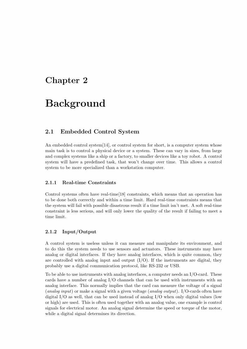
2.1.2 Input/Output
A control system is useless unless it can measure and manipulate its environment, andto do this the system needs to use sensors and actuators. These instruments may haveanalog or digital interfaces. If they have analog interfaces, which is quite common, theyare controlled with analog input and output (I/O). If the instruments are digital, theyprobably use a digital communication protocol, like RS-232 or USB.
To be able to use instruments with analog interfaces, a computer needs an I/O-card. Thesecards have a number of analog I/O channels that can be used with instruments with ananalog interface. This normally implies that the card can measure the voltage of a signal(analog input) or make a signal with a given voltage (analog output). I/O-cards often havedigital I/O as well, that can be used instead of analog I/O when only digital values (lowor high) are used. This is often used together with an analog value, one example is controlsignals for electrical motor. An analog signal determine the speed or torque of the motor,while a digital signal determines its direction.
4 CHAPTER 2. BACKGROUND
2.2 Atmel AVR32 Architecture
The new AVR32 microprocessor architecture from Atmel Norway claims to be an architec-ture for the 21st century[2]. Most other processors increase their throughput1 by increasingthe clock frequency. The AVR32 microprocessor aims to give high throughput with a slowclock. Since power consumption is directly related to clock frequency, this means that itcan do the same work with less power. This will be an important characteristic in thefuture, since we will use more and more gadgets that use battery as a power source, likehand-held music- and video-players.
Low power consumption is also important for control systems. Many systems needs tohave low weight, low cost and a long battery time. Since batteries normally are heavy andexpensive, both weight and cost will decrease if the power consumption decrease.
2.2.1 STK1000
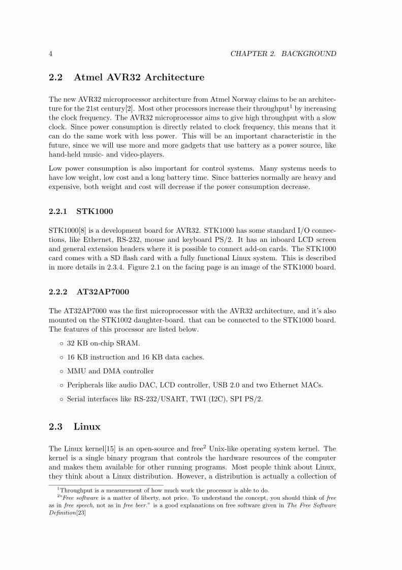
STK1000[8] is a development board for AVR32. STK1000 has some standard I/O connec-tions, like Ethernet, RS-232, mouse and keyboard PS/2. It has an inboard LCD screenand general extension headers where it is possible to connect add-on cards. The STK1000card comes with a SD flash card with a fully functional Linux system. This is describedin more details in 2.3.4. Figure 2.1 on the facing page is an image of the STK1000 board.
2.2.2 AT32AP7000
The AT32AP7000 was the first microprocessor with the AVR32 architecture, and it’s alsomounted on the STK1002 daughter-board. that can be connected to the STK1000 board.The features of this processor are listed below.
32 KB on-chip SRAM.
16 KB instruction and 16 KB data caches.
MMU and DMA controller
Peripherals like audio DAC, LCD controller, USB 2.0 and two Ethernet MACs.
Serial interfaces like RS-232/USART, TWI (I2C), SPI PS/2.
2.3 Linux
The Linux kernel[15] is an open-source and free2 Unix-like operating system kernel. Thekernel is a single binary program that controls the hardware resources of the computerand makes them available for other running programs. Most people think about Linux,they think about a Linux distribution. However, a distribution is actually a collection of
1Throughput is a measurement of how much work the processor is able to do.2”Free software is a matter of liberty, not price. To understand the concept, you should think of free
as in free speech, not as in free beer.” is a good explanations on free software given in The Free SoftwareDefinition[23]
2.3. LINUX 5
Figure 2.1: STK1000 development board
programs, including the Linux kernel, that can easily be installed on a computer. Theymay consist of thousands of programs, but it’s only the kernel that is called Linux.
2.3.1 Linux Control Systems
Linux based operating systems are used in many different systems, from servers and work-stations to embedded systems like control systems. In recent years they have been usedmore and more in embedded systems. This will most likely increase further in the future,as indicated in the article in Datarespons’ magazine Interrupt [22]. Below is a list overreasons to use Linux in a control system, some of these are also mentioned in the article.
Linux and many of the programs running on Linux are free and open-source.
A Linux system is configurable, scalable and able to run on many different hardwareplatforms.
Linux is a stable and well tested operating system kernel.
Linux has many skilled users and developers who are often willing to help.
6 CHAPTER 2. BACKGROUND
2.3.2 Kernel Mode and User Mode
Most processor architectures has the ability to run code in different levels of privilege. Thex86 architecture has four, called ring 0 to ring 3. The AVR32 architecture[11] has twonormal modes, called Supervisor and Application (equivalent to ring 0 and ring 3). Othermodes are reserved for interrupts and exceptions.
As described on page 19 of Understanding Linux kernel [20], Linux systems uses two ofthese levels, kernel mode and user mode. Kernel mode are often refereed to as ring 0 [19]and is the highest privileged mode. A normal program executes in user mode but is ableto switch to kernel mode when requesting a service that the kernel provides. Kernel modeis only used when necessary, and only when allowed by the kernel.
User mode programs can switch to kernel mode or communicate with the kernel throughdifferent interfaces. A system call are functions running in kernel mode that can be calledfrom user mode, and they are described in chapter 10 of [20]. Signals are used to sendnotifications between user mode programs, or between the kernel and user mode programs,and are described in chapter 11 of [20]. The kernel works as a layer between hardwaredevices and user mode programs, and this is usually done with Device Drivers. Which aredescribed in 2.3.3.
2.3.3 Linux Device Driver
A device driver is code that controls a device, normally this is some kind of hardware.How device drivers works are described in Linux Device Driver [21] and in chapter 13 ofUnderstanding the Linux kernel [20]. A device driver has to be either a part of the kernelor a kernel module that can be linked into a running kernel. Devices are identified in theLinux kernel with a major and a minor number. These are numbers that the device driverhas allocated for the devices it controls.
Device drivers are often used to make it possible for user mode programs to use the devicescontrolled by the driver. A user mode program access the driver through special files inthe file system, called device nodes. These are normally located in the /dev directory. Auser mode program can read, write or do other file operations on a node, just as if it wasa normal file. When accessing a node with the same major and minor number as a device,the user-space program is actually accessing the driver of this device.
There are two types of device nodes, which corresponds to two different types of devices.Character or char devices are devices that receive or send data serially, while block devicesreceive or send big chunks of data at the time. Most devices except hard drives and RAMare char devices.
2.3.4 AVR32 Linux
AVR32 Linux[3] is a porting3 of the Linux kernel done by Atmel Norway. This meansthat it’s a version of the Linux kernel that are able to run on this processor architecture.
3Porting software is to do modifications so the software can run on other processors or operating systems,further description in [16].
2.4. RAPID PROTOTYPING 7
AVR32 support was included in the mainstream Linux kernel 2.6.19 release, but it doesn’tcontain all the drivers for AVR32 and STK1000 board. To get these, it’s necessary to usethe AVR32 Linux kernel patches from the AVR32 Linux web page (http://avr32linux.org).Basic system utilities and development tools for the AVR32 architecture can also be foundon this web page.
The STK1000 board comes with a SD flash card with a runnable Linux system. Thissystem includes a patched 2.6.16 version of the Linux kernel and Busybox 4. STK1000 usesU-Boot5, which will boot from the SD card by default. By changing the boot arguments inU-Boot, it is also possible to boot from network. The advantage of network booting is thatthe kernel image, file system and programs that all have been developed on a workstationcan be used by AVR32 Linux through the network. This makes development much fastersince new files and programs don’t have to be transferred to a physical medium like a SDcard.
To communicate with the AVR32 Linux from a workstation, it’s possible to use both aserial connection and telnet via Ethernet. Both of these solutions are available on thepreinstalled Linux system on the SD flash card. They both give a text-based terminal justlike a normal text-based Linux system would give. The AVR32 Linux system also has asmall web server, that in an embedded control system can be used to display a simple webpage with status information and measurement logging.
2.3.5 AVR32 Linux development tools
Atmel Norway has also ported development tools for use with the AVR32 Linux platform.These tools are available precompiled for different Linux distributions and for Windows,or they could be compiled from source. The development tools for AVR32 Linux includesthe tools below.
Binutils - GNU Binary utilities for handling object code.
GCC - GNU compiler.
uClibc - A lightweight version of the standard C-library.
u-boot - A boot loader for many different processor architectures.
GDB - GNU debugger that together with a GDB-server on AVR32 can debug coderunning on AVR32.
GDB-server - A server version of GDB that can run on the AVR32.
2.4 Rapid Prototyping
In computer engineering, rapid prototyping is a development technique that rapidly make asimplified version of a system. This prototype usually implements a part of the complete
4Busybox is a lightweight program that includes the functionality of most small Linux applications thatan embedded system will need in a single binary file.
5U-Boot (Universal bootloader) is a bootloader that can be used on many different platforms, amongthem the AVR32.
8 CHAPTER 2. BACKGROUND
system, that are necessary to test thoroughly. These are often important parts of thesystem, and the result of the tests can be used to avoid premature decisions. A typicalapplication is to design the user-interface with a rapid prototyping tool. This allows fastand cheap development of a prototype that the users of the system can test and evaluate.User evaluation can often give important information that is difficult to obtain by othermeans.
2.4.1 Rapid Prototyping Control Systems
For control systems, rapid prototyping tools can be used to generate control algorithmsfrom graphical visualization of mathematical systems. It’s easier and faster to developa control system with a tool like this than to write code. It’s also easier to change andsearch for errors. These generated algorithms can be tested both against simulated andactual systems, which is useful during development. Parts of the algorithms can also beused in the complete system.
Two well known tools for simulating and prototyping of control systems are Matlab andLabview. Matlab was originally a program for matrix computation (the name stands forMATrix LABoratory), but it has evolved into a large collection of mathematical software.Simulink is one of the programs in this collection, and it’s a program for simulatingdynamical system represented by graphical block diagrams. Code can be generated fromthese block diagrams, making it ideal for rapid prototyping.
Labview uses a data flow language that describes how data flows between different nodesof a system, often a control system. This language is called G and are the basis ofLabview. The nodes are representations of physical or logical components and can beplaced and connected using a graphical interface. The G language is a parallel and platformindependent6 language and is well suited for prototyping.
6Except some special functions
Chapter 3
AVR32 Linux on STK1000
This chapter describes how to install development tools for AVR32 Linux, and how toconfigure it for development. Some of the problems encountered while working with thisversion of Linux are described as well.
3.1 Development Tools
Installing the development tools are very easy when using the Ubuntu[10] Linux distri-bution that was used during this thesis. This distribution uses the Apt[17] (AdvancedPackaging Tool) package management tool, that can install software from servers definedin the /etc/apt/sources.list file. To add the server containing the AVR32 developmenttools, the following line should be added to this file.
deb http ://www. atmel . no/ beta ware / avr32/ubuntu/dapper binary /
To install the tools, execute the following commands, and answer yes to all questions.
sudo apt i tude updatesudo apt i tude i n s t a l l avr32−l inux−deve l
If this approach doesn’t work, or instructions for installing on other platforms, check theAVR freaks wiki http://www.avrfreaks.net/wiki.
3.1.1 Compiling Development Tools from Source
It’s also possible to compile the development tools from source, and this was necessaryduring the start of this thesis. Then, the precompiled tools had a few bugs. Compilingthe development tools from source is still the only option if special features is needed.Instructions for doing this can be found at http://avr32linux.org/twiki/bin/view/Main/GettingStarted.
9
10 CHAPTER 3. AVR32 LINUX ON STK1000
3.2 AVR32 Linux Kernel Versions
Some of the early AVR32 versions of the Linux kernel had some problems. Both the2.6.16, 2.6.18 and 2.6.19 versions were tested. During these tests the following problemswas encountered.
The 2.6.16 version had problems linking with the pthread library. The SPI driverworked, but had problems with stability and returned wrong data.
The SPI driver did not work in the 2.6.18 version.
The 2.6.19 version also had problems linking with the pthread library.
It’s also possible that the problems with the pthread library were because of uClibc,the library used by AVR32 Linux. After switching to the 2.6.20 kernel version and newprecompiled development tools, no kernel or library related problems were encountered.
3.3 Configure booting over Network
2.3.4 explains that the STK1000 can be configured to boot over network, and that this isa suitable solution during development.
3.3.1 Workstation Configuration
To boot the STK1000 over network, it’s required that the workstation has two differentservers. A TFTP-server (Trivial File Transfer Protocol) are a simple protocol for transfer-ring small files and are used by the boot loader on STK1000 to download the kernel image.A NFS-server (Network File System) are a standard UNIX server for sharing files, and willbe used to share a root filesystem with the STK1000 board. For a Ubuntu workstationthese two servers are installed by using aptitude, and the following commands.˜$ sudo apt i tude i n s t a l l t f tpd x inetd nfs−kerne l−s e r v e r portmap
The TFTP-server are configured by adding the following text into /etc/xinetd.conf.s e r v i c e t f t ppro to co l = udpport = 69dgram = dgramwait = yesuser = nobodys e r v e r = /usr / sb in / in . t f tpds e r v e r a r g s = / t f tpboo td i s ab l e = no
The following commands are used to start the server. This is only necessary to do once,afterwards the server starts by itself.˜$ sudo mkdir / t f tpboo t˜$ sudo chmod −R 777 / t f tpboo t˜$ sudo chown −R nobody / t f tpboo t˜$ sudo / e tc / i n i t . d/ x inetd s t a r t
3.3. CONFIGURE BOOTING OVER NETWORK 11
The TFTP-server are now started and shares the directory /tftpboot. If a kernel imageare copied to this directory, the STK1000 are able to download and boot this image.
The NFS-server are configured by sharing a directory with NFS. This are done in the/etc/exportfs file, and below is an example of a line that will share a directory./home/oyvindne/master / f s 129 . 241 . 187 . 1/24 ( rw , no root squash , async )
To restart the NFS-server with new configuration, the following commands are used:˜$ sudo / e tc / i n i t . d/portmap r e s t a r t˜$ sudo / e tc / i n i t . d/ nfs−kerne l−s e r v e r r e s t a r t˜$ sudo expo r t f s −a
3.3.2 Configure U-Boot
U-Boot (Universal Bootloader) are the boot loader used on STK1000. To configure it,the STK1000 has to be connected to a workstation with a serial cable. The Workstationshould use a serial terminal program like minicom to connect to the STK1000. Duringstart up of the STK1000 board, the space bar should be pressed to enter the U-Bootcommand line. Here, the bootargs variable has to be changed, and a tftpip variable hasto be created. The following commands modify these variables. If used on other systems,the IP addresses to the host computer and the path to the NFS-server has to be changed.setenv t f t p i p 129 . 241 . 187 . 212setenv bootargs conso l e=ttyUS0 ip=dhcp root=/dev/ n f s n f s r o o t =129 .241 .187 .212 :/home/
oyvindne/master / f s i n i t=/sb in / i n i t fbmem=900ksaveenv

12 CHAPTER 3. AVR32 LINUX ON STK1000
Chapter 4
Preliminary tests of AVR32
This chapter describes some preliminary tests performed on the STK1000 board beforecontinuing the work. It was important to reveal any weaknesses the AVR32 architecturemay have, so the control system platform can be designed to avoid them as much aspossible. It’s also important to test that planned solutions can be used on AVR32.
4.1 Floating-point and Fixed-point operation Test
The AVR32 architecture don’t have a hardware floating-point unit (FPU). This meansthat floating-point operations have to be done with software emulation. Since MatlabRTW generated code normally has many floating-point operations, it’s important to knowthe processors ability to calculate these. The test referred to in this chapter was set up toreveal this. A test for fixed-point calculations was performed as well, and the two resultswere compared.
The tests consists of 100 million either floating-point or fixed-point multiplications. Thetest program measures the time used by these operations, and calculate the number ofmicroseconds and clock cycles one operation takes (on average). To measure the time, thestopwatch library was used. This library was developed during the thesis, to make timemeasurements easier, and consists of stopwatch.h and stopwatch.c that can be foundin the appendix C.3.5 and C.3.6.
4.1.1 Code
1 #include <s t d i o . h>23 #include ”stopwatch . h”45 #define COUNT 1000000006 #define CPU CLOCK 140 // Clock frequency o f AVR32 on STK1000 .78 int main ( )9
10 long a ;11 f loat b ;12 long usec , i ;13 f loat usecPerCalc , t i ck sPerCa l c ;
14 CHAPTER 4. PRELIMINARY TESTS OF AVR32
14 struct sStopWatch watch ;1516 StartStopWatch(&watch ) ;17 for ( i =0; i<COUNT; i++)18 a = 64343∗52342; // Random in t e g e r s .19 20 usec = StopStopWatch(&watch ) ;2122 usecPerCalc = ( f loat ) ( usec ) / ( f loat )COUNT;23 t i ck sPerCa l c = usecPerCalc ∗ ( f loat )CPU CLOCK;2425 p r i n t f ( ” t o t a l time : %i \n” , usec ) ;26 p r i n t f ( ”microseconds per c a l c u l a t i o n : %f \n” , usecPerCalc ) ;27 p r i n t f ( ”c l o ck t i c k per c a l c u l a t i o n : %f \n” , t i ck sPerCa l c ) ;2829 StartStopWatch(&watch ) ;30 for ( i =0; i<COUNT; i++)31 b = 234092098437498.249872398472398∗209347802947239.290834732984723; //
Random doub l e s .32 33 usec = StopStopWatch(&watch ) ;3435 usecPerCalc = ( f loat ) ( usec ) / ( f loat )COUNT;36 t i ck sPerCa l c = usecPerCalc ∗ ( f loat )CPU CLOCK;3738 p r i n t f ( ” t o t a l time : %i \n” , usec ) ;39 p r i n t f ( ”microseconds per c a l c u l a t i o n : %f \n” , usecPerCalc ) ;40 p r i n t f ( ”c l o ck t i c k per c a l c u l a t i o n : %f \n” , t i ck sPerCa l c ) ;41
4.1.2 Result
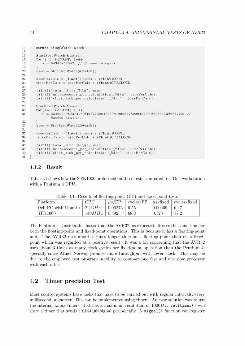
Table 4.1 shows how the STK1000 preformed on these tests compared to a Dell workstationwith a Pentium 4 CPU.
Table 4.1: Results of floating-point (FP) and fixed-point testsPlatform CPU µs/FP cycles/FP µs/fixed cycles/fixedDell PC with Ubuntu 2.4GHz 0.00273 6.55 0.00269 6.47STK1000 140MHz 0.492 68.8 0.123 17.2
The Pentium is considerable faster than the AVR32, as expected. It uses the same time forboth the floating-point and fixed-point operations. This is because it has a floating-pointunit. The AVR32 uses about 4 times longer time on a floating-point than on a fixed-point which was regarded as a positive result. It was a bit concerning that the AVR32uses about 3 times as many clock cycles per fixed-point operation than the Pentium 4,specially since Atmel Norway promise more throughput with lower clock. This may bedue to the employed test program inability to compare one fast and one slow processorwith each other.
4.2 Timer precision Test
Most control systems have tasks that have to be carried out with regular intervals, everymillisecond or shorter. This can be implemented using timers. An easy solution was to usethe internal Linux timers, that has a maximum resolution of 1000Hz. setitimer() willstart a timer that sends a SIGALRM signal periodically. A signal() function can register
4.2. TIMER PRECISION TEST 15
this signal and select a function that runs each time the SIGALRM is received. This is alldone inside a user mode program.
The test consists of 10000 periods of 10ms each. The reason for not choosing 1ms whichis the lowest available timer, is that the standard Ubuntu kernel doesn’t have the highestprecision timer (This can be changed by recompiling the kernel, but the test is just asgood with 10ms). The periodic tasks was created using the periodicTask library, thatwas developed to make it easy to make and start periodic tasks. This library consists ofperiodicTask.h and periodicTask.c, that are in the appendix C.3.3 and C.3.4. Thestopwatch library mentioned in 4.1 was also used.
4.2.1 Code
1 #include <s t d i o . h>2 #include <math . h>34 #include ”p e r i o d i c t a s k . h”5 #include ”stopwatch . h”67 #define COUNT 100008 #define PERIODE 19
10 int main ( )11 12 int i , usec [COUNT] , totUsec ;13 f loat totVar , avrUsec , avrVar , avrStd ;14 struct sPer iod icTask task ;15 struct sStopWatch watch ;1617 In i tPe r i od i cTa sk s ( ) ;18 Star tPer iod i cTask (&task , PERIODE) ;1920 StartStopWatch(&watch ) ;2122 for ( i =0; i<COUNT; i++)23 WaitPeriodicTask(&task ) ;24 usec [ i ] = StopStopWatch(&watch ) ;25 i f ( i != COUNT − 1) StartStopWatch(&watch ) ;26 2728 totUsec = 0 ;29 for ( i =5; i<COUNT−5; i++)30 totUsec = totUsec + usec [ i ] ;31 totVar = totVar + pow ( ( ( f loat ) usec [ i ] − 10000∗PERIODE) ,2 ) ;32 33 avrUsec = ( ( f loat ) ( totUsec ) ) /(COUNT−10) ;34 avrVar = totVar /(COUNT−10) ;35 avrStd = sq r t ( avrVar ) ;3637 p r i n t f ( ”Average per i ode time : %f \n” , avrUsec ) ;38 p r i n t f ( ”Variance : %f \n” , avrVar ) ;39 p r i n t f ( ”Standard de r i va t e : %f \n” , avrStd ) ;40
4.2.2 Result
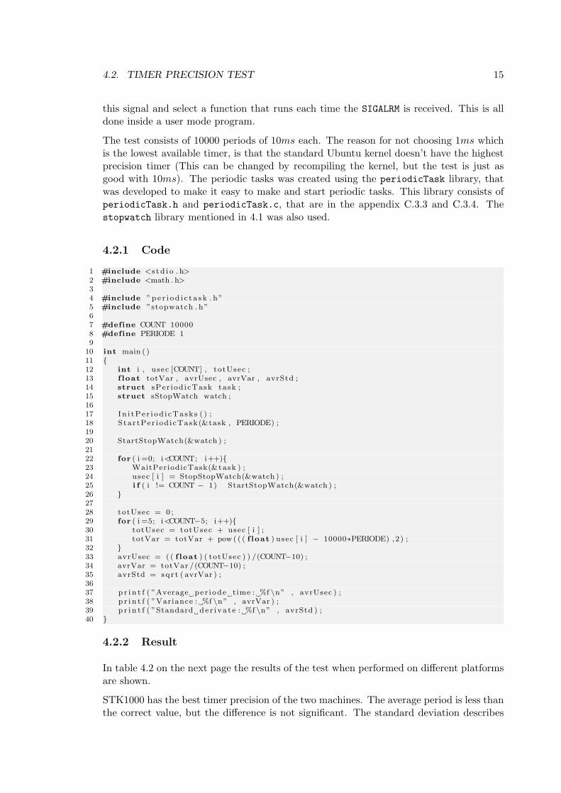
In table 4.2 on the next page the results of the test when performed on different platformsare shown.
STK1000 has the best timer precision of the two machines. The average period is less thanthe correct value, but the difference is not significant. The standard deviation describes

16 CHAPTER 4. PRELIMINARY TESTS OF AVR32
Table 4.2: Results of timer testsPlatform CPU Average Standard deviationDell Workstation running Ubuntu 7.04 2.4GHz 10013.09µs 2057µsSTK1000 running avr32 Linux 150MHz 9994.91µs 7.25µs
Sine Wave Scope
1s
Integrator
1
Gain
Figure 4.1: First order low-pass passive filter
how much the results differ from the expected value, and it considerable lower for theSTK1000. This is because the workstation computer has many programs running, andthese will disturb the timer.
4.3 Test of Matlab Real-Time Workshop Generated Code
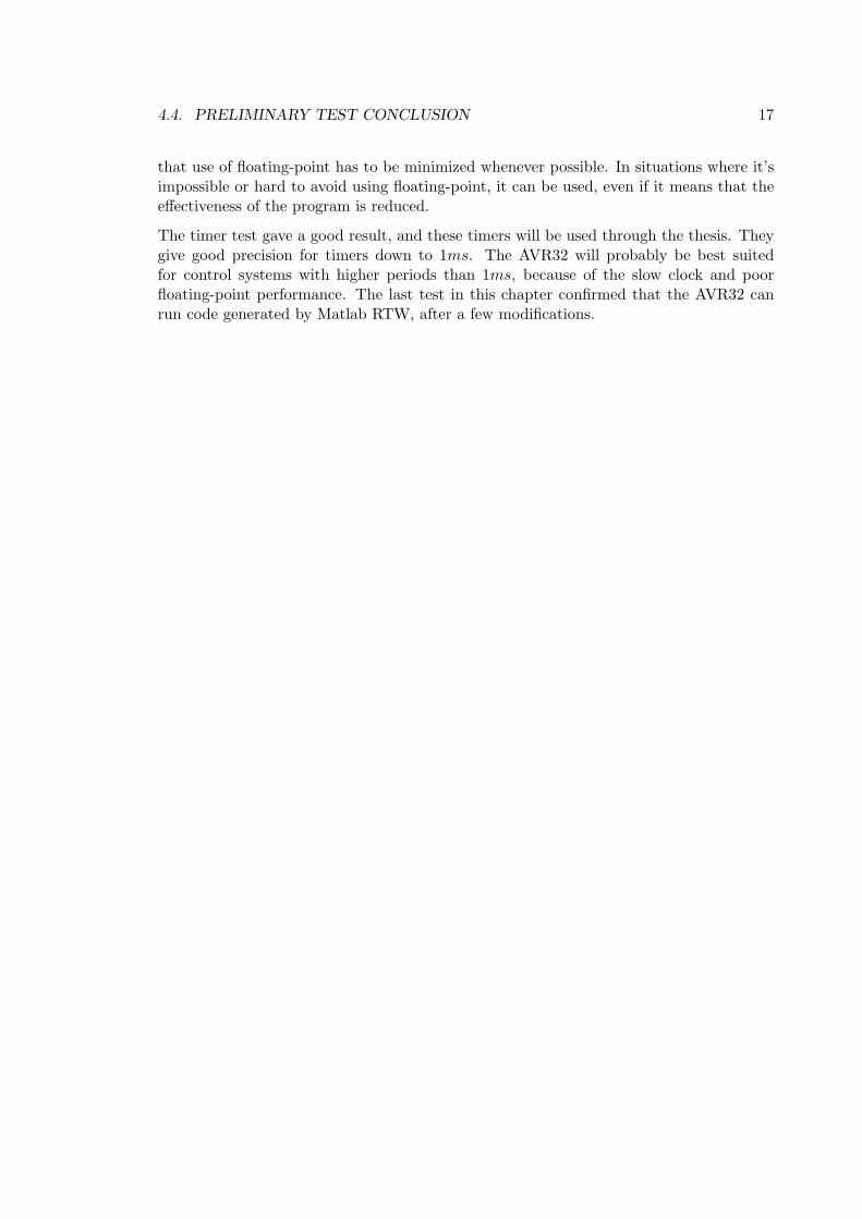
One of the goals of this thesis was to configure Matlab RTW to be used as a rapidprototyping tool for the control system. This made it important to check that it waspossible to run RTW code on AVR32. A simple test system was created, consisting of again block and an integration block, and generated code from it. The GRT system targetwas used when generating code, see 11.1.1. Figure 4.1 describes the simple test system.
To compile the code for AVR32, it was necessary to change the generated makefile. AddingCC=avr32-linux-gcc to the Makefile (see 11.2.2 for the exact location) specifies that theAVR32 compiler should be used. When running the Makefile with this addition, theMakefile returned the following output.avr32−l inux−gcc −c −O − f f l o a t −s t o r e −fPIC −m32 −DUSE RTMODEL −ans i −pedant ic −
DMODEL=t e s t −DRT −DNUMST=2 −DTID01EQ=1 −DNCSTATES=1 −DUNIX −DMT=0 −DHAVESTDIO−I . −I . . −I / usr / l o c a l /matlab/ s imul ink / inc lude −I / usr / l o c a l /matlab/ extern /inc lude −I / usr / l o c a l /matlab/rtw/c/ s r c −I / usr / l o c a l /matlab/rtw/c/ s r c /ext mode/common −I /home/oyvindne/diplom/matlab/ s impleTest / t e s t g r t r tw −I /home/oyvindne/diplom/matlab/ s impleTest −I / usr / l o c a l /matlab/rtw/c/ l i b s r c r t n o n f i n i t e . c
cc1 : e r r o r : i n v a l i d opt ion ’32 ’make : ∗∗∗ [ r t n o n f i n i t e . o ] Error 1
The compilation ends with an error, since the AVR32 compiler doesn’t understand the-m32 flag. When removing this from the Makefile, the compilation is successful, and thecompiled program runs on the STK1000 card with no problems. Notice that during thefirst AVR32 compilation in a folder, many object files are compiled, since the defaultones from Matlab are all i386 specific. These files are only compiled once, so futurecompilations will take much shorter time.
4.4 Preliminary Test Conclusion
After doing these tests it was concluded that the AVR32 processor can be used in a controlsystem, even if the floating-point performance wasn’t impressive. This weakness implies
4.4. PRELIMINARY TEST CONCLUSION 17
that use of floating-point has to be minimized whenever possible. In situations where it’simpossible or hard to avoid using floating-point, it can be used, even if it means that theeffectiveness of the program is reduced.
The timer test gave a good result, and these timers will be used through the thesis. Theygive good precision for timers down to 1ms. The AVR32 will probably be best suitedfor control systems with higher periods than 1ms, because of the slow clock and poorfloating-point performance. The last test in this chapter confirmed that the AVR32 canrun code generated by Matlab RTW, after a few modifications.

18 CHAPTER 4. PRELIMINARY TESTS OF AVR32
Chapter 5
Preliminary tests of I/O-card
2.1.2 describes why control systems need I/O, specially analog I/O. Since the STK1000don’t have any analog I/O, a I/O-card was developed. This chapther performs test to findout if the chosen ATmega128 microcontroller is able to work as a controller for the I/O-card, and if the SPI-bus is useable as communication between STK1000 and the I/O-card.
5.1 AVR Microcontroller
5.1.1 ATmega128
An ATmega128[1] microcontroller was used to control the I/O-card. This is a 8-bit mi-crocontroller from the AVR family from Atmel Norway. ATmega128 is a 64-pin micro-controller with 128kB flash and 4096B SRAM, making it one of the AVRs with highestspecification. Some of the features of the ATmega128 are shown below.
8-channel 10-bit ADC (analog input).
2-channel 16-bit PWM (Pulse Width Modulator) timers with 3 subchannels each.These can be used as analog output.
2 8-bit timers.
2 USARTs that can be converted RS-232.
Several external interrupts.
SPI (Serial Peripheral Interface).
TWI (Two-Wire Interface).
Several general digital I/O pins (digital I/O).
With these built-in features, there was no need for extra analog I/O components. Thismicrocontroller could do both the communication with the STK1000 board and the actualI/O. This made the design of an I/O card easier.
20 CHAPTER 5. PRELIMINARY TESTS OF I/O-CARD
5.1.2 STK500/501
The STK500[9] is an AVR development board that is well suited for early stage devel-opment of AVR microcontrollers. To use this board with the ATmega128 model, it’snecessary to use the expansion module STK501, which supports 64 pins surface mountedAVRs. When using STK500/501 all the pins of the used AVR are available as headers,and all the basic components that the AVR often uses like clock source and RS-232 circuitare ready to use.
This development board was used to test how different features of ATmega128 could beused before making a prototype I/O-card. These test helped minimizing the number ofdesign errors on the prototype.
5.2 Analog input
Analog input are used to measure the voltage of signals, and are done with ADCs (Analog-Digital Converter). These are important for a control system, to receive measurement datafrom sensors. The I/O-card will use the ADC on the ATmega128. This is a 8-channel10-bit ADC that can measure the voltage between two pins or between a pin and ground.This ADC can convert voltages between GND and AVCC (analog supply).
5.2.1 Test of ATmega128 ADC
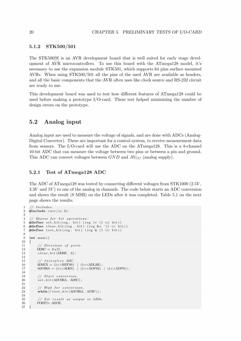
The ADC of ATmega128 was tested by connecting different voltages from STK1000 (2.5V ,3.3V and 5V ) to one of the analog in channels. The code below starts an ADC conversionand shows the result (8 MSB) on the LEDs after it was completed. Table 5.1 on the nextpage shows the results.
1 // Inc ludes .2 #include <avr / i o . h>34 // Macros f o r b i t opera t ions .5 #define s e t b i t ( reg , b i t ) ( reg |= (1 << b i t ) )6 #define c l e a r b i t ( reg , b i t ) ( reg &= ˜(1 << b i t ) )7 #define t e s t b i t ( reg , b i t ) ( reg & (1 << b i t ) )89 int main ( )
10 11 // Direc t ion o f por t s .12 DDRC = 0 x f f ;13 c l e a r b i t (DDRF, 0) ;1415 // I n i t i a l i z e ADC.16 ADMUX = (1<<REFS0) | (1<<ADLAR) ;17 ADCSRA = (1<<ADEN) | (1<<ADPS2) | (1<<ADPS1) ;1819 // S tar t convers ion .20 s e t b i t (ADCSRA, ADSC) ;2122 // Wait f o r convers ion .23 while ( ! t e s t b i t (ADCSRA, ADIF) ) ;2425 // Set r e s u l t as output to LEDs.26 PORTC= ADCH;27
5.3. ANALOG OUTPUT 21
Table 5.1: Results of ADC testVoltage Multimeter voltage ADC result (8 bit) ADC result in voltage2.5V 2.50V 113 2.21V3.3V 3.27V 136 2.66V5V 5.00V 210 4.12V
As seen in table 5.1, the results from the ADC were not very accurate. All results were80% − 90% of the correct value. It might be because of an error with the STK500/501card or maybe the ATmega128.
5.3 Analog Output
Analog output is used to make an analog voltage. This is important for control system, sothey are able to control actuators. The I/O-card will use PWM (Pulse-Width Modulation)of the ATmega128 to generate an analog signal. PWM is a digital signal with a constantfrequency and a controllable duty-cycle. The duty-cycle is a value that describes howmuch of the period the digital signal is high. A 50% duty-cycle means that the signal ishigh half of the periode, then low the rest of the periode, and will look like square-wawesignal.
5.3.1 Generating Analog Signal from PWM
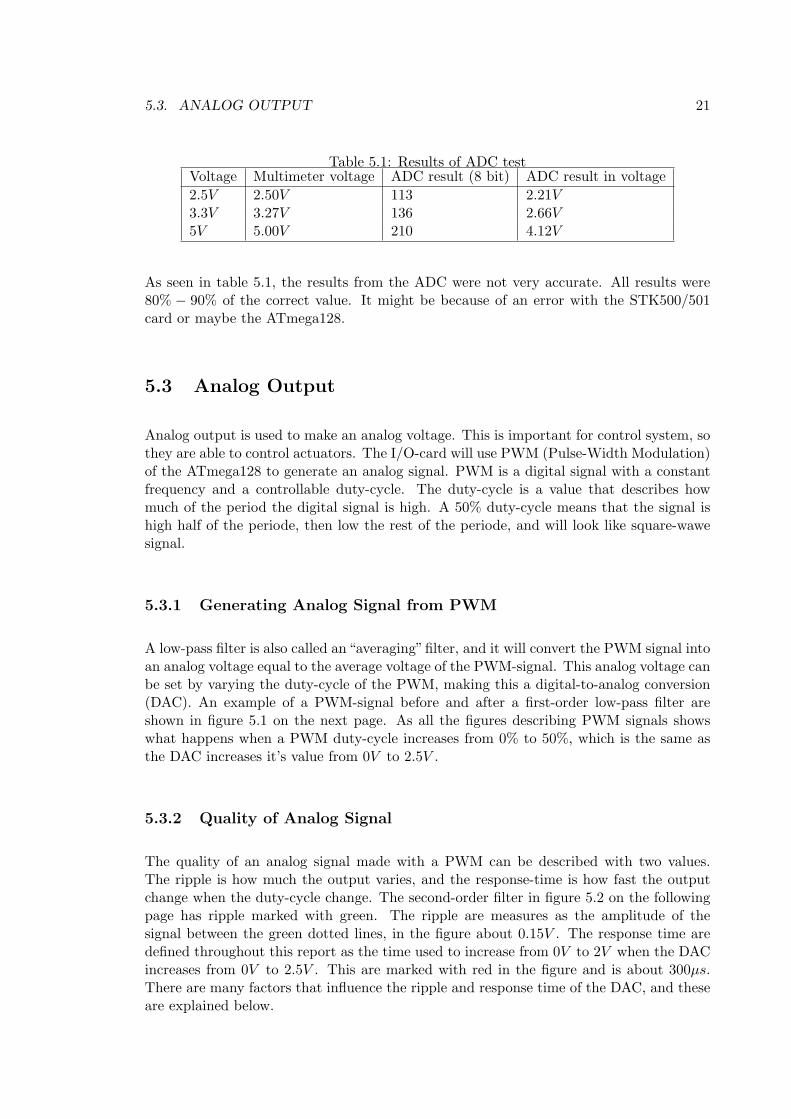
A low-pass filter is also called an“averaging”filter, and it will convert the PWM signal intoan analog voltage equal to the average voltage of the PWM-signal. This analog voltage canbe set by varying the duty-cycle of the PWM, making this a digital-to-analog conversion(DAC). An example of a PWM-signal before and after a first-order low-pass filter areshown in figure 5.1 on the next page. As all the figures describing PWM signals showswhat happens when a PWM duty-cycle increases from 0% to 50%, which is the same asthe DAC increases it’s value from 0V to 2.5V .
5.3.2 Quality of Analog Signal
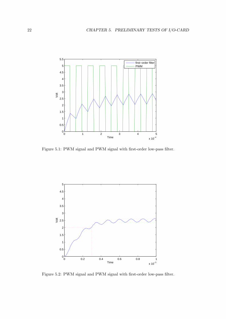
The quality of an analog signal made with a PWM can be described with two values.The ripple is how much the output varies, and the response-time is how fast the outputchange when the duty-cycle change. The second-order filter in figure 5.2 on the followingpage has ripple marked with green. The ripple are measures as the amplitude of thesignal between the green dotted lines, in the figure about 0.15V . The response time aredefined throughout this report as the time used to increase from 0V to 2V when the DACincreases from 0V to 2.5V . This are marked with red in the figure and is about 300µs.There are many factors that influence the ripple and response time of the DAC, and theseare explained below.
22 CHAPTER 5. PRELIMINARY TESTS OF I/O-CARD
0 1 2 3 4 5
x 10−4
0
0.5
1
1.5
2
2.5
3
3.5
4
4.5
5
5.5
Time
Vol
t
first−order filterPWM
Figure 5.1: PWM signal and PWM signal with first-order low-pass filter.
0 0.2 0.4 0.6 0.8 1
x 10−3
0
0.5
1
1.5
2
2.5
3
3.5
4
4.5
5
Time
Vol
t
Figure 5.2: PWM signal and PWM signal with first-order low-pass filter.
5.3. ANALOG OUTPUT 23
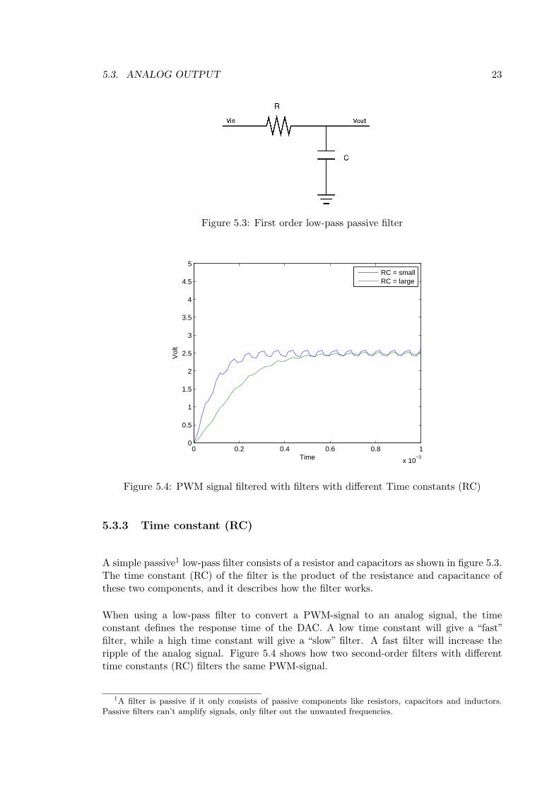
Figure 5.3: First order low-pass passive filter
0 0.2 0.4 0.6 0.8 1
x 10−3
0
0.5
1
1.5
2
2.5
3
3.5
4
4.5
5
Time
Vol
t
RC = smallRC = large
Figure 5.4: PWM signal filtered with filters with different Time constants (RC)
5.3.3 Time constant (RC)
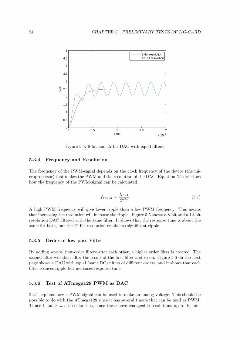
A simple passive1 low-pass filter consists of a resistor and capacitors as shown in figure 5.3.The time constant (RC) of the filter is the product of the resistance and capacitance ofthese two components, and it describes how the filter works.
When using a low-pass filter to convert a PWM-signal to an analog signal, the timeconstant defines the response time of the DAC. A low time constant will give a “fast”filter, while a high time constant will give a “slow” filter. A fast filter will increase theripple of the analog signal. Figure 5.4 shows how two second-order filters with differenttime constants (RC) filters the same PWM-signal.
1A filter is passive if it only consists of passive components like resistors, capacitors and inductors.Passive filters can’t amplify signals, only filter out the unwanted frequencies.
24 CHAPTER 5. PRELIMINARY TESTS OF I/O-CARD
0 0.5 1 1.5 2
x 10−3
0
0.5
1
1.5
2
2.5
3
3.5
4
4.5
5
Time
Vol
t
8−bit resolution12−bit resolution
Figure 5.5: 8-bit and 12-bit DAC with equal filters.
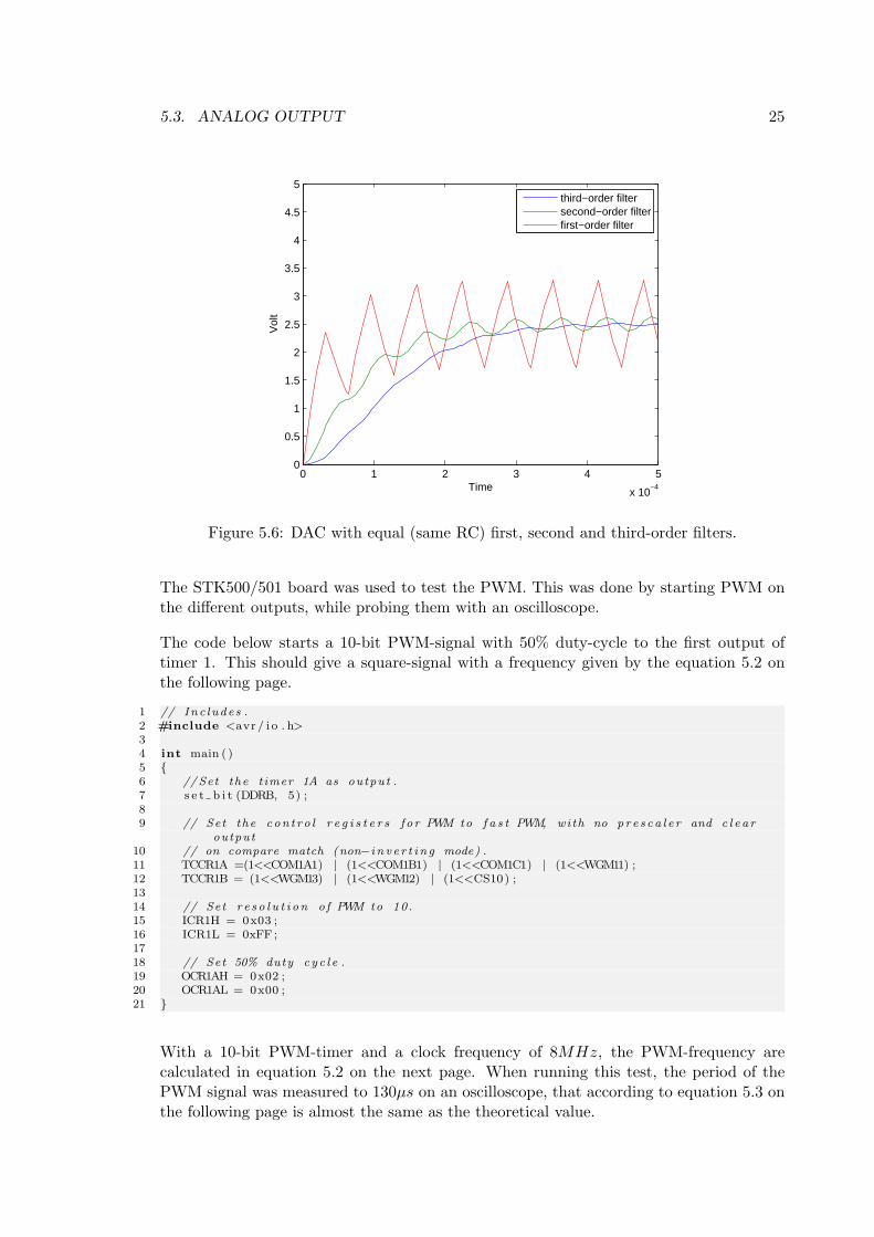
5.3.4 Frequency and Resolution
The frequency of the PWM-signal depends on the clock frequency of the device (the mi-croprocessor) that makes the PWM and the resolution of the DAC. Equation 5.1 describeshow the frequency of the PWM-signal can be calculated.
fPWM =fclock
2bits(5.1)
A high PWM frequency will give lower ripple than a low PWM frequency. This meansthat increasing the resolution will increase the ripple. Figure 5.5 shows a 8-bit and a 12-bitresolution DAC filtered with the same filter. It shows that the response time is about thesame for both, but the 12-bit resolution result has significant ripple.
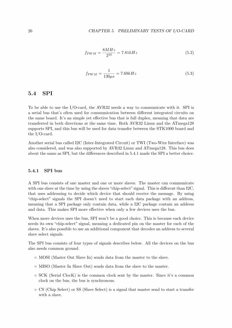
5.3.5 Order of low-pass Filter
By adding several first-order filters after each other, a higher order filter is created. Thesecond filter will then filter the result of the first filter and so on. Figure 5.6 on the nextpage shows a DAC with equal (same RC) filters of different orders, and it shows that eachfilter reduces ripple but increases response time.
5.3.6 Test of ATmega128 PWM as DAC
5.3.1 explains how a PWM-signal can be used to make an analog voltage. This should bepossible to do with the ATmega128 since it has several timers that can be used as PWM.Timer 1 and 3 was used for this, since these have changeable resolutions up to 16 bits.
5.3. ANALOG OUTPUT 25
0 1 2 3 4 5
x 10−4
0
0.5
1
1.5
2
2.5
3
3.5
4
4.5
5
Time
Vol
t
third−order filtersecond−order filterfirst−order filter
Figure 5.6: DAC with equal (same RC) first, second and third-order filters.
The STK500/501 board was used to test the PWM. This was done by starting PWM onthe different outputs, while probing them with an oscilloscope.
The code below starts a 10-bit PWM-signal with 50% duty-cycle to the first output oftimer 1. This should give a square-signal with a frequency given by the equation 5.2 onthe following page.
1 // Inc ludes .2 #include <avr / i o . h>34 int main ( )5 6 // Set the timer 1A as output .7 s e t b i t (DDRB, 5) ;89 // Set the con t ro l r e g i s t e r s f o r PWM to f a s t PWM, with no p r e s ca l e r and c l e a r
output10 // on compare match (non−i n v e r t i n g mode) .11 TCCR1A =(1<<COM1A1) | (1<<COM1B1) | (1<<COM1C1) | (1<<WGM11) ;12 TCCR1B = (1<<WGM13) | (1<<WGM12) | (1<<CS10) ;1314 // Set r e s o l u t i on o f PWM to 10.15 ICR1H = 0x03 ;16 ICR1L = 0xFF ;1718 // Set 50% duty cy c l e .19 OCR1AH = 0x02 ;20 OCR1AL = 0x00 ;21
With a 10-bit PWM-timer and a clock frequency of 8MHz, the PWM-frequency arecalculated in equation 5.2 on the next page. When running this test, the period of thePWM signal was measured to 130µs on an oscilloscope, that according to equation 5.3 onthe following page is almost the same as the theoretical value.
26 CHAPTER 5. PRELIMINARY TESTS OF I/O-CARD
fPWM =8MHz
210= 7.81kHz (5.2)
fPWM =1
130µs= 7.69kHz (5.3)
5.4 SPI
To be able to use the I/O-card, the AVR32 needs a way to communicate with it. SPI isa serial bus that’s often used for communication between different integrated circuits onthe same board. It’s an simple yet effective bus that is full duplex, meaning that data aretransferred in both directions at the same time. Both AVR32 Linux and the ATmega128supports SPI, and this bus will be used for data transfer between the STK1000 board andthe I/O-card.
Another serial bus called I2C (Inter-Integrated Circuit) or TWI (Two-Wire Interface) wasalso considered, and was also supported by AVR32 Linux and ATmega128. This bus doesabout the same as SPI, but the differences described in 5.4.1 made the SPI a better choice.
5.4.1 SPI bus
A SPI bus consists of one master and one or more slaves. The master can communicatewith one slave at the time by using the slaves“chip-select”signal. This is different than I2C,that uses addressing to decide which device that should receive the message. By using“chip-select” signals the SPI doesn’t need to start each data package with an address,meaning that a SPI package only contain data, while a I2C package contain an addressand data. This makes SPI more effective when only a few devices uses the bus.
When more devices uses the bus, SPI won’t be a good choice. This is because each deviceneeds its own “chip-select” signal, meaning a dedicated pin on the master for each of theslaves. It’s also possible to use an additional component that decodes an address to severalslave select signals.
The SPI bus consists of four types of signals describes below. All the devices on the busalso needs common ground.
MOSI (Master Out Slave In) sends data from the master to the slave.
MISO (Master In Slave Out) sends data from the slave to the master.
SCK (Serial ClocK) is the common clock sent by the master. Since it’s a commonclock on the bus, the bus is synchronous.
CS (Chip Select) or SS (Slave Select) is a signal that master send to start a transferwith a slave.
5.5. TEST OF SPI COMMUNICATION BETWEEN AVR32 AND ATMEGA128 27
Figure 5.7: How data are transferred between SPI master and slave.
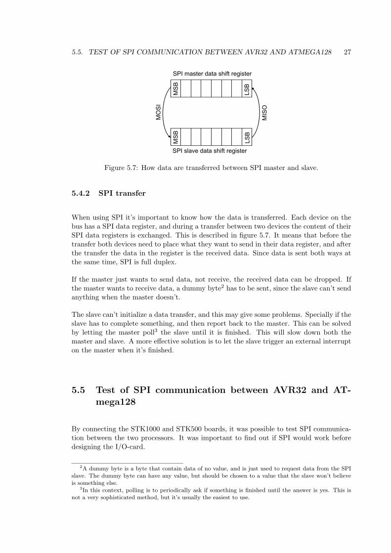
5.4.2 SPI transfer
When using SPI it’s important to know how the data is transferred. Each device on thebus has a SPI data register, and during a transfer between two devices the content of theirSPI data registers is exchanged. This is described in figure 5.7. It means that before thetransfer both devices need to place what they want to send in their data register, and afterthe transfer the data in the register is the received data. Since data is sent both ways atthe same time, SPI is full duplex.
If the master just wants to send data, not receive, the received data can be dropped. Ifthe master wants to receive data, a dummy byte2 has to be sent, since the slave can’t sendanything when the master doesn’t.
The slave can’t initialize a data transfer, and this may give some problems. Specially if theslave has to complete something, and then report back to the master. This can be solvedby letting the master poll3 the slave until it is finished. This will slow down both themaster and slave. A more effective solution is to let the slave trigger an external interrupton the master when it’s finished.
5.5 Test of SPI communication between AVR32 and AT-mega128
By connecting the STK1000 and STK500 boards, it was possible to test SPI communica-tion between the two processors. It was important to find out if SPI would work beforedesigning the I/O-card.
2A dummy byte is a byte that contain data of no value, and is just used to request data from the SPIslave. The dummy byte can have any value, but should be chosen to a value that the slave won’t believeis something else.
3In this context, polling is to periodically ask if something is finished until the answer is yes. This isnot a very sophisticated method, but it’s usually the easiest to use.
28 CHAPTER 5. PRELIMINARY TESTS OF I/O-CARD
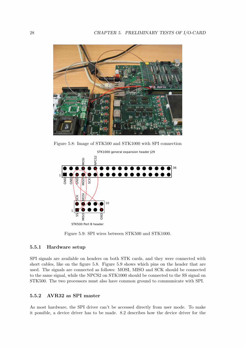
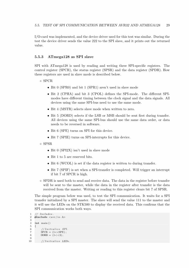
Figure 5.8: Image of STK500 and STK1000 with SPI connection
Figure 5.9: SPI wires between STK500 and STK1000.
5.5.1 Hardware setup
SPI signals are available on headers on both STK cards, and they were connected withshort cables, like on the figure 5.8. Figure 5.9 shows which pins on the header that areused. The signals are connected as follows: MOSI, MISO and SCK should be connectedto the same signal, while the NPCS2 on STK1000 should be connected to the SS signal onSTK500. The two processors must also have common ground to communicate with SPI.
5.5.2 AVR32 as SPI master
As most hardware, the SPI driver can’t be accessed directly from user mode. To makeit possible, a device driver has to be made. 8.2 describes how the device driver for the
5.5. TEST OF SPI COMMUNICATION BETWEEN AVR32 AND ATMEGA128 29
I/O-card was implemented, and the device driver used for this test was similar. During thetest the device driver sends the value 222 to the SPI slave, and it prints out the returnedvalue.
5.5.3 ATmega128 as SPI slave
SPI with ATmega128 is used by reading and writing three SPI-specific registers. Thecontrol register (SPCR), the status register (SPSR) and the data register (SPDR). Howthese registers are used in slave mode is described below.
SPCR
• Bit 0 (SPR0) and bit 1 (SPR1) aren’t used in slave mode
• Bit 2 (CPHA) and bit 3 (CPOL) defines the SPI-mode. The different SPI-modes have different timing between the clock signal and the data signals. Alldevices using the same SPI-bus need to use the same mode.
• Bit 4 (MSTR) selects slave mode when written to zero.
• Bit 5 (DORD) selects if the LSB or MSB should be sent first during transfer.All devices using the same SPI-bus should use the same data order, or dataneeds to be reversed in software.
• Bit 6 (SPE) turns on SPI for this device.
• Bit 7 (SPIE) turns on SPI-interrupts for this device.
SPSR
• Bit 0 (SPI2X) isn’t used in slave mode
• Bit 1 to 5 are reserved bits.
• Bit 6 (WCOL) is set if the data register is written to during transfer.
• Bit 7 (SPIF) is set when a SPI-transfer is completed. Will trigger an interruptif bit 7 of SPCR is high.
SPDR is used both to send and receive data. The data in the register before transferwill be sent to the master, while the data in the register after transfer is the datareceived from the master. Writing or reading to this register clears bit 7 of SPSR.
The simple program below was used, to test the SPI communication. It waits for a SPItransfer initialized by a SPI master. The slave will send the value 111 to the master andit will use the LEDs on the STK500 to display the received data. This confirms that theSPI communication works both ways.
1 // Inc ludes .2 #include <avr / i o . h>34 int main ( )5 6 // I n i t i a l i z e SPI .7 SPCR = (1<<SPE) ;8 DDRB = (1<<3) ;9
10 // I n i t i a l i z e LEDs.
30 CHAPTER 5. PRELIMINARY TESTS OF I/O-CARD
11 DDRD = 0 x f f ;12 PORTD = 0 ;1314 // Set data .15 SPDR = 111 ;1617 //Wait f o r t r an s f e r .18 while ( ! ( SPSR & (1<<SPIF) ) ) ;1920 //Send rece i v ed data to LEDs and loop f o r e v e r .21 PORTD = SPDR;22 while (1 ) ;23
5.5.4 Result
The test of a simple SPI transfer between the two STK boards was successful. This meansthat it will be possible to use SPI as communication between AVR32 and an I/O-card. Thehighest SPI frequency that worked was measured to about 1.90MHz with an oscilloscope.According to the ATmega128 data sheet[1] both the low and high period of the SCK signalhas to be longer than 2 clock cycles. When the clock frequency is 8MHz this means thatthe highest theoretical frequency is 2MHz, that are close to the measured value.
Chapter 6
Prototype I/O-card
This chapter desribes the design and production of the first of two I/O-card versionsproduced during this thesis. The first card is called the prototype card, and was designedto be ideal for testing and debugging.
6.1 PCB Software
A PCB (Printed-Circuit Board) is an epoxy bonded fiberglass sheet with copper layers thatcan be etched or milled off and leave electrical circuits. Most electronics are implementedon PCBs, and they may have different numbers of layers, and each layer can containcircuits.
There are a number of different software solutions for designing PCBs. In this thesis thefreeware version of Eagle[4] was used. This program has a limitation on the size of thefinished card, and it can’t design cards with more than two layers. This wasn’t a problem,since the maximum size (8x10cm) and two layers were enough for the purpose.
6.2 Features
This card was designed to have these features:
ATmega128 with 16 MHz crystal as controller.
JTAG-interface for ATmega128.
Reset button for ATmega128.
RS-232 connection for debugging to a serial port on a workstation.
Header ready to connect to general expansion header on STK1000 with power-supply,SPI and interrupt signals.
Jumper for choosing between external power-supply and power-supply from STK1000.
2 AVR32 interrupts that can be triggered from ATmega128.
31
32 CHAPTER 6. PROTOTYPE I/O-CARD
2 AVR32 interrupts that can be triggered externally.
2 ATmega128 interrupts that can be triggered externally.
6 channel 8 to 12-bits analog output.
8 channel 10-bits analog input.
Common ground for both STK1000 and STK500.
8 channel digital output.
8 channel digital input.
SPI signals available on ”debug” header.
6.3 Components
The components used for this card:
ATmega128 microcontroller ([1]).
MAX233 UART to RS-232 IC ([5]).
Two 100nF capacitors for decoupling ATmega128 and MAX233).
Linear voltage regulator (7805) with capacitors ([7]).
100nF capacitor and 10µH inductor for LC filter on analog supply.
16MHz crystal and two 18pF capacitors for crystal circuit for ATmega128.
One button, 10kΩ resistor and 100nF capacitor for reset button for ATmega128.
Six second-order RC-filter for filtering PWM signal to analog value. Two resistorsand two capacitors for each filter.
3 operational amplifiers (MC1458) ([6]).
Screw clamps for connecting different signals.
2x5 male header for JTAG connection.
2x18 male header for STK1000 connection.
1x3 male header with jumper for power-supply selection.
1x8 header for debug signals.
6.4 Schematic
The schematic of a circuit is a logical representation of how the different parts connectsto each other. When designing a circuit, it’s normally best to start with this. The wholeschematic are in the appendix B.1. Different sections of the circuit are presented below.Be aware that these are the orignal schematics of the prototype, and have errors describedin 6.7.
6.4. SCHEMATIC 33
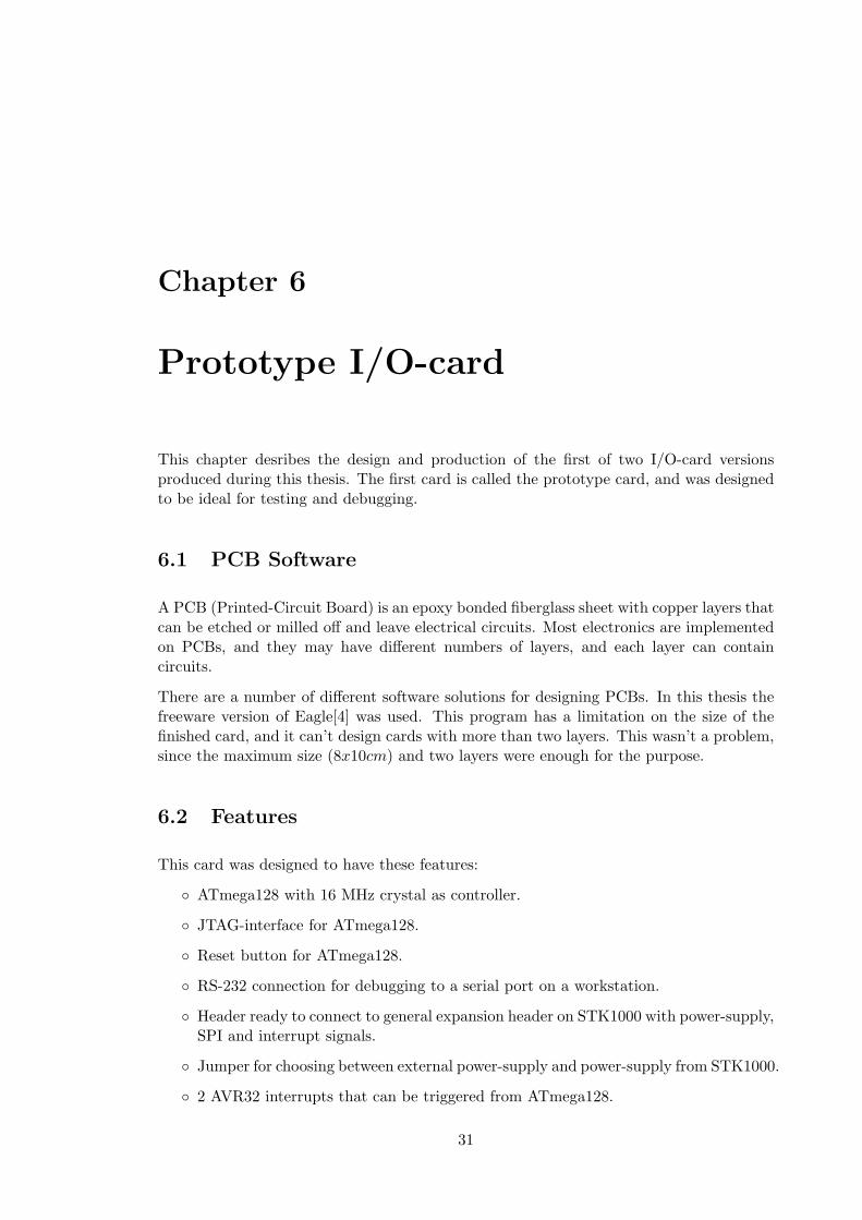
Figure 6.1: Power circuit
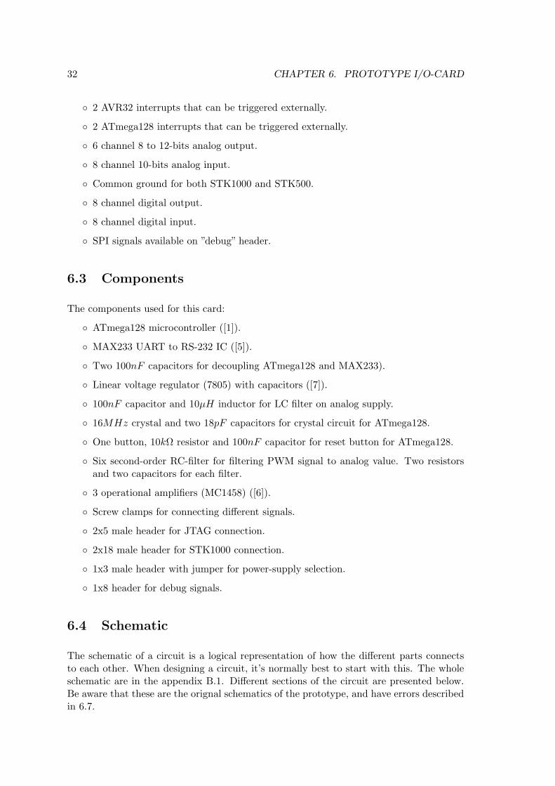
Figure 6.2: Reset, crystal and analog reference circuits for ATmega128
6.4.1 Power Circuit
Figure 6.1 shows the Power circuit used for the I/O-card. To the left are the power jackconnector, for connecting a AC/DC adapter. In the bottom right corner, there is a linearvoltage regulator 7805[7] that gives out a stable 5V voltage source. This component needsa capacitor on both input and output to work properly. On the top there is a 3-pin header.A jumper is used to choose what kind of voltage source the rest of the card will use, eitherthe output from the voltage regulator or the 5V signal from the STK1000 card.
34 CHAPTER 6. PROTOTYPE I/O-CARD
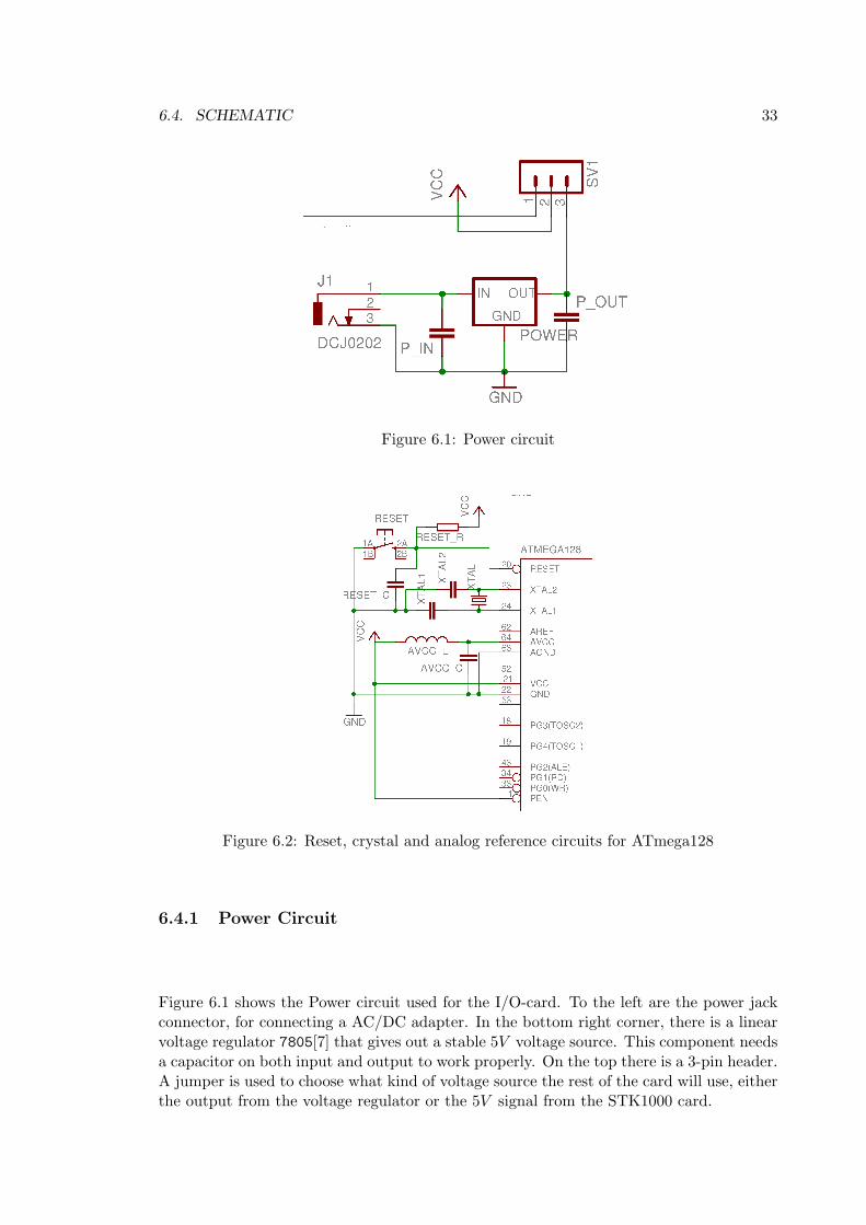
Figure 6.3: JTAG header and analog input connectors
6.4.2 Reset, Crystal and Analog Supply Circuit
Figure 6.2 on the previous page shows the reset, crystal and analog reference circuits forthe ATmega128. The reset circuit provides a button that will “pull-down” the active-lowreset port of the microcontroller when pushed. This will reset the processor. This circuitalso has a “pull-up” resistor that makes sure the reset port is high when the button isn’tpushed.
The crystal circuit was made to give the ATmega128 a stable and high frequency clocksource. The main reason for this is that a higher clock frequency will make the PWMsignal better suited as a base for making analog out signals.
The analog supply is necessary to make the ATmega128 able to read analog input signals.The crystal and analog supply circuits are implemented after specification given in theATmega128 data sheet [1].
6.4.3 JTAG header and Analog Input Connectors
Figure 6.3 shows the JTAG header for the ATmega128 and screw clamps for the analoginput signals. The JTAG header was added to allow a AVR JTAG ICE (either originalor mk2) to connect, program and debug the ATmega128. The analog input screw clampswas mounted at the side of the I/O card, and makes it easy to connect wires with analogsignals to the ADC of the ATmega128. Four of ATmega128s ports was used both by theJTAG header as analog input. This shouldn’t be a problem as long as no analog signalsare connected to these ports when using the JTAG header.
6.4. SCHEMATIC 35
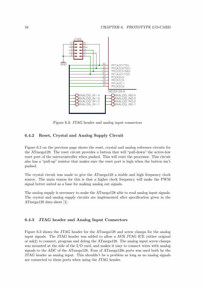
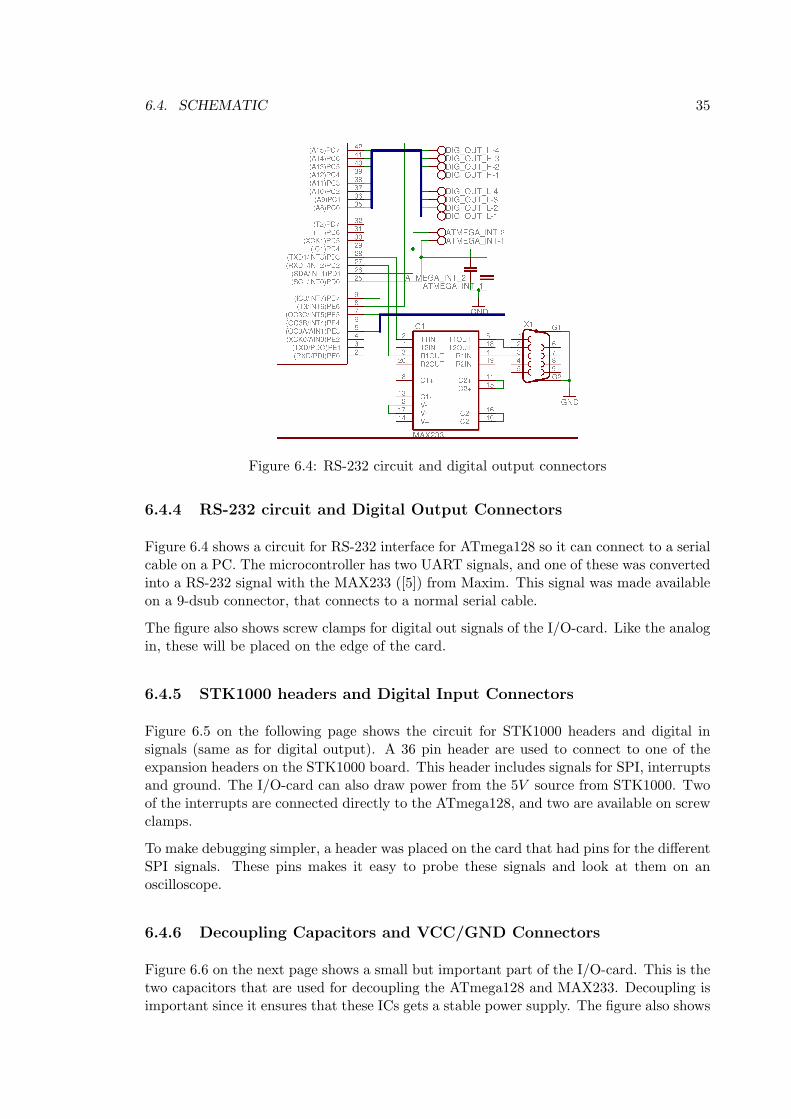
Figure 6.4: RS-232 circuit and digital output connectors
6.4.4 RS-232 circuit and Digital Output Connectors
Figure 6.4 shows a circuit for RS-232 interface for ATmega128 so it can connect to a serialcable on a PC. The microcontroller has two UART signals, and one of these was convertedinto a RS-232 signal with the MAX233 ([5]) from Maxim. This signal was made availableon a 9-dsub connector, that connects to a normal serial cable.
The figure also shows screw clamps for digital out signals of the I/O-card. Like the analogin, these will be placed on the edge of the card.
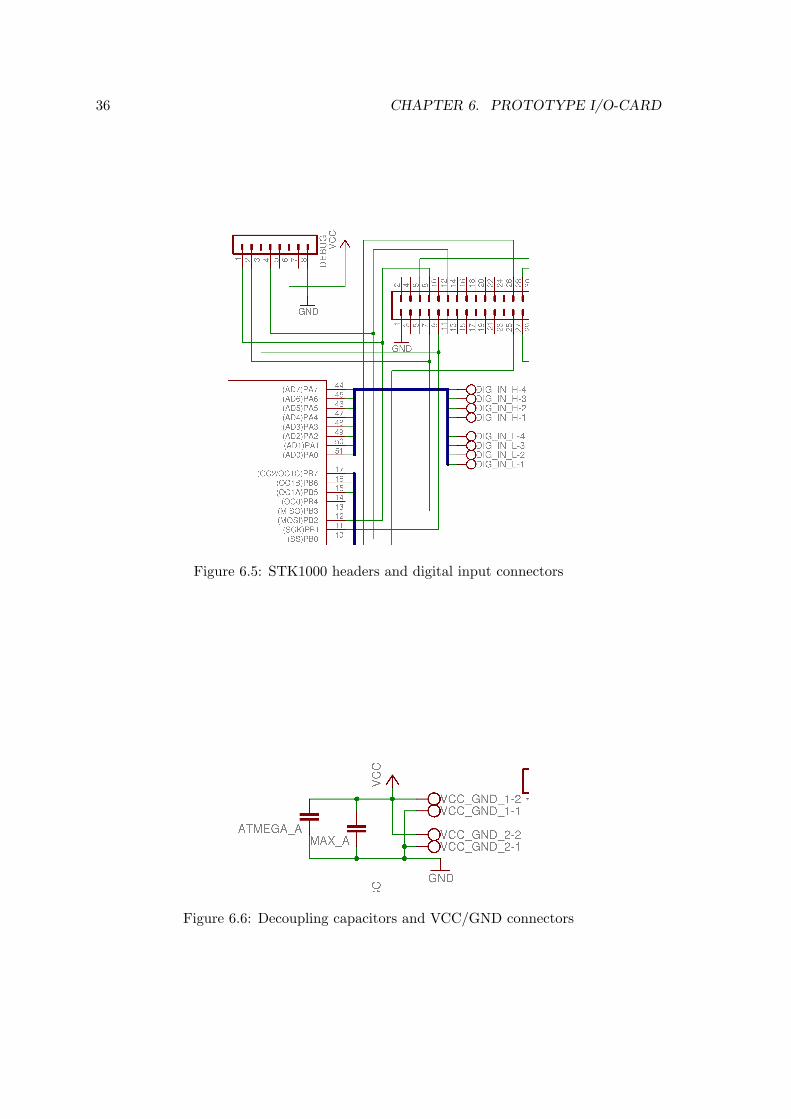
6.4.5 STK1000 headers and Digital Input Connectors
Figure 6.5 on the following page shows the circuit for STK1000 headers and digital insignals (same as for digital output). A 36 pin header are used to connect to one of theexpansion headers on the STK1000 board. This header includes signals for SPI, interruptsand ground. The I/O-card can also draw power from the 5V source from STK1000. Twoof the interrupts are connected directly to the ATmega128, and two are available on screwclamps.
To make debugging simpler, a header was placed on the card that had pins for the differentSPI signals. These pins makes it easy to probe these signals and look at them on anoscilloscope.
6.4.6 Decoupling Capacitors and VCC/GND Connectors
Figure 6.6 on the next page shows a small but important part of the I/O-card. This is thetwo capacitors that are used for decoupling the ATmega128 and MAX233. Decoupling isimportant since it ensures that these ICs gets a stable power supply. The figure also shows
36 CHAPTER 6. PROTOTYPE I/O-CARD
Figure 6.5: STK1000 headers and digital input connectors
Figure 6.6: Decoupling capacitors and VCC/GND connectors
6.4. SCHEMATIC 37
Figure 6.7: Analog out circuit
two screw clamps that has VCC and GND signals. These signals are available for devicesconnecting to the I/O card, and are necessary because all I/O signal needs a reference.
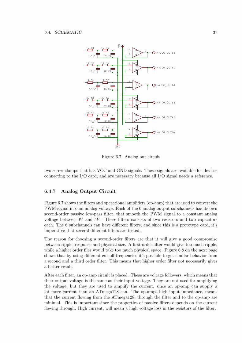
6.4.7 Analog Output Circuit
Figure 6.7 shows the filters and operational amplifiers (op-amp) that are used to convert thePWM-signal into an analog voltage. Each of the 6 analog output subchannels has its ownsecond-order passive low-pass filter, that smooth the PWM signal to a constant analogvoltage between 0V and 5V . These filters consists of two resistors and two capacitorseach. The 6 subchannels can have different filters, and since this is a prototype card, it’simperative that several different filters are tested.
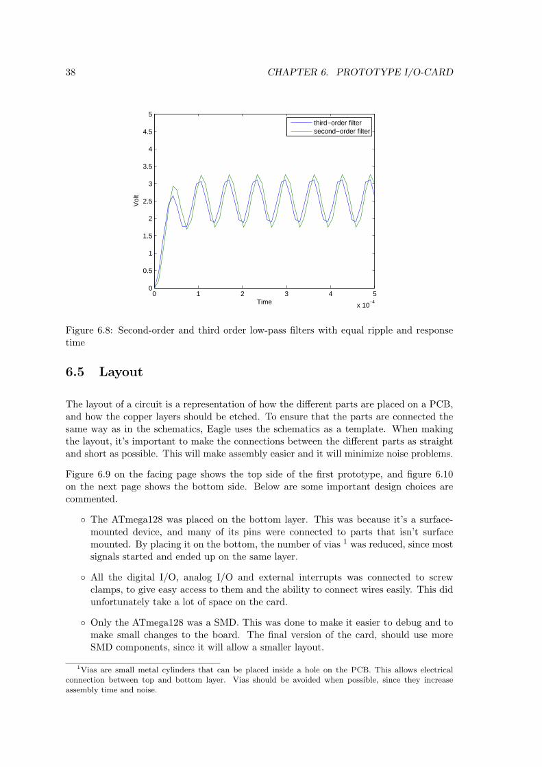
The reason for choosing a second-order filters are that it will give a good compromisebetween ripple, response and physical size. A first-order filter would give too much ripple,while a higher order filer would take too much physical space. Figure 6.8 on the next pageshows that by using different cut-off frequencies it’s possible to get similar behavior froma second and a third order filter. This means that higher order filter not necessarily givesa better result.
After each filter, an op-amp circuit is placed. These are voltage followers, which means thattheir output voltage is the same as their input voltage. They are not used for amplifyingthe voltage, but they are used to amplify the current, since an op-amp can supply alot more current than an ATmega128 can. The op-amps high input impedance, meansthat the current flowing from the ATmega128, through the filter and to the op-amp areminimal. This is important since the properties of passive filters depends on the currentflowing through. High current, will mean a high voltage loss in the resistors of the filter.
38 CHAPTER 6. PROTOTYPE I/O-CARD
0 1 2 3 4 5
x 10−4
0
0.5
1
1.5
2
2.5
3
3.5
4
4.5
5
Time
Vol
t
third−order filtersecond−order filter
Figure 6.8: Second-order and third order low-pass filters with equal ripple and responsetime
6.5 Layout
The layout of a circuit is a representation of how the different parts are placed on a PCB,and how the copper layers should be etched. To ensure that the parts are connected thesame way as in the schematics, Eagle uses the schematics as a template. When makingthe layout, it’s important to make the connections between the different parts as straightand short as possible. This will make assembly easier and it will minimize noise problems.
Figure 6.9 on the facing page shows the top side of the first prototype, and figure 6.10on the next page shows the bottom side. Below are some important design choices arecommented.
The ATmega128 was placed on the bottom layer. This was because it’s a surface-mounted device, and many of its pins were connected to parts that isn’t surfacemounted. By placing it on the bottom, the number of vias 1 was reduced, since mostsignals started and ended up on the same layer.
All the digital I/O, analog I/O and external interrupts was connected to screwclamps, to give easy access to them and the ability to connect wires easily. This didunfortunately take a lot of space on the card.
Only the ATmega128 was a SMD. This was done to make it easier to debug and tomake small changes to the board. The final version of the card, should use moreSMD components, since it will allow a smaller layout.
1Vias are small metal cylinders that can be placed inside a hole on the PCB. This allows electricalconnection between top and bottom layer. Vias should be avoided when possible, since they increaseassembly time and noise.
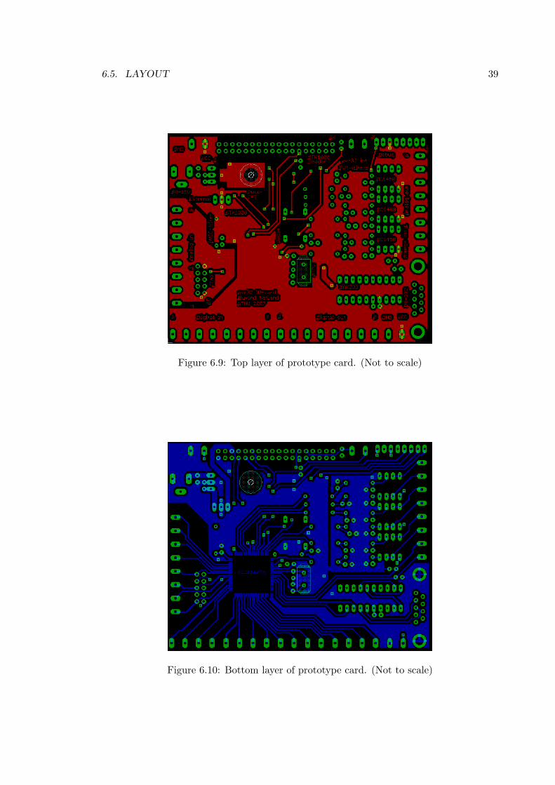
6.5. LAYOUT 39
Figure 6.9: Top layer of prototype card. (Not to scale)
Figure 6.10: Bottom layer of prototype card. (Not to scale)
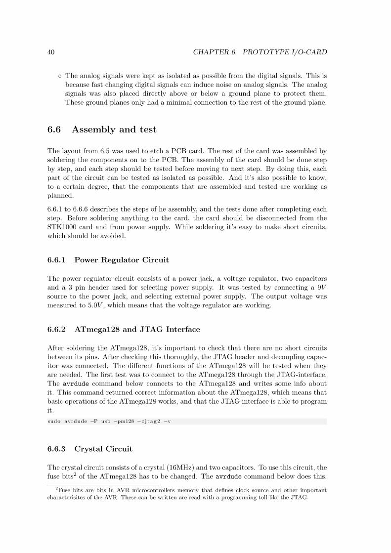
40 CHAPTER 6. PROTOTYPE I/O-CARD
The analog signals were kept as isolated as possible from the digital signals. This isbecause fast changing digital signals can induce noise on analog signals. The analogsignals was also placed directly above or below a ground plane to protect them.These ground planes only had a minimal connection to the rest of the ground plane.
6.6 Assembly and test
The layout from 6.5 was used to etch a PCB card. The rest of the card was assembled bysoldering the components on to the PCB. The assembly of the card should be done stepby step, and each step should be tested before moving to next step. By doing this, eachpart of the circuit can be tested as isolated as possible. And it’s also possible to know,to a certain degree, that the components that are assembled and tested are working asplanned.
6.6.1 to 6.6.6 describes the steps of he assembly, and the tests done after completing eachstep. Before soldering anything to the card, the card should be disconnected from theSTK1000 card and from power supply. While soldering it’s easy to make short circuits,which should be avoided.
6.6.1 Power Regulator Circuit
The power regulator circuit consists of a power jack, a voltage regulator, two capacitorsand a 3 pin header used for selecting power supply. It was tested by connecting a 9Vsource to the power jack, and selecting external power supply. The output voltage wasmeasured to 5.0V , which means that the voltage regulator are working.
6.6.2 ATmega128 and JTAG Interface
After soldering the ATmega128, it’s important to check that there are no short circuitsbetween its pins. After checking this thoroughly, the JTAG header and decoupling capac-itor was connected. The different functions of the ATmega128 will be tested when theyare needed. The first test was to connect to the ATmega128 through the JTAG-interface.The avrdude command below connects to the ATmega128 and writes some info aboutit. This command returned correct information about the ATmega128, which means thatbasic operations of the ATmega128 works, and that the JTAG interface is able to programit.sudo avrdude −P usb −pm128 −c j t ag2 −v
6.6.3 Crystal Circuit
The crystal circuit consists of a crystal (16MHz) and two capacitors. To use this circuit, thefuse bits2 of the ATmega128 has to be changed. The avrdude command below does this.
2Fuse bits are bits in AVR microcontrollers memory that defines clock source and other importantcharacterisitcs of the AVR. These can be written are read with a programming toll like the JTAG.
6.6. ASSEMBLY AND TEST 41
When starting up the ATmega128 with the crystal circuit and new fuse bits, the crystalpins were probed with an oscilloscope. The result was a sinus signal with a frequency of16MHz, which means that the crystal circuit works.sudo avrdude −P usb −pm128 −c j t ag2 −U l f u s e :w: 0xFE :m −U hfuse :w: 0 x89 :m −U e fu s e :w: 0
xFF :m
6.6.4 RS-232 and Reset Circuits
These two elements were best to test together. The RS-232 circuit consists of the MAX233IC and a 9 dsub connectors (connector used by serial port of a standard computer). Thereset circuit consists of a button, a resistor and a capacitor. The RS-232 circuit was testedby sending a byte of data from the card, when it was connected to the workstation with aserial-cable. The code below sends one byte with a baud rate of 19.2kbps. When runningthis code, the workstation received the byte when using a program like minicom. Thereset circuit worked since the same byte was received by the workstation each time thereset button was pressed.
1 // Inc ludes .2 #include <avr / i o . h>34 int main ( )5 6 // Set d i r e c t i on r e g i s t e r s7 s e t b i t (DDRD, 3) ;8 c l e a r b i t (DDRD, 4) ;9
10 // BAUD rate = 19.2 k11 UBBR1H = 0 ;12 UBBR1L = 51 ;1314 // Enable both transmit and r e c e i v e15 UCSR1B = (1<<RXEN1) | (1<<TXEN1) ;1617 // Use 8 b i t data , no pa r i t y and 2 s top b i t s .18 UCSR1C = (1<<UCSZ11) | (1<<UCSZ10) | (1<<USBS1) ;1920 // S tar t sending by wr i t i n g to the send data r e g i s t e r .21 UDR1 = ’A ’ ;
6.6.5 Headers for STK1000 and debugging
These headers were tested by connecting the header to the general expansion header (J29)on the STK1000 board, and try the same test as in 5.5. Since the SPI communication alsoworked through the header, it meant that the header are connected properly. To check ifthe STK1000 can be used as power supply for the I/O card, the jumper was from externalpower supply to STK1000. This worked, which meant that the STK1000 can supply theATmega128 with power.
6.6.6 ADC Supply Filter
The filter for the ADC supply is a LC-filer, and it’s used to filter out digital noise, sothe analog reference is kept as stable as possible. This is to ensure that the analog in is
42 CHAPTER 6. PROTOTYPE I/O-CARD
as accurate as possible. On this prototype card, the inductor of the LC-filter was shortcircuited, since no inductor of correct value was available. The inductor works as a shortcircuit for DC current, but it stops AC current. So replacing the inductor with a shortcircuit will just make the filter stop high frequency noise less effective.
6.6.7 Analog Output Circuit
The analog output circuit was assembled with different filters, that were used to find afilter for the final I/O-card. 9.2.2 describes the different filters that were tested and theresults.
6.7 Errors in Schematic
During the assembly and test of the prototype, the following errors was found in the design.
VCC of the JTAG-interface wasn’t connected to the VCC of the board.
The operational amplifiers don’t work as they should, see 9.2.
The 9-dsub connector for the RS-232 connection weren’t connected correctly. Pinnumber 5 should be connected to ground, and the cable shield shouldn’t.
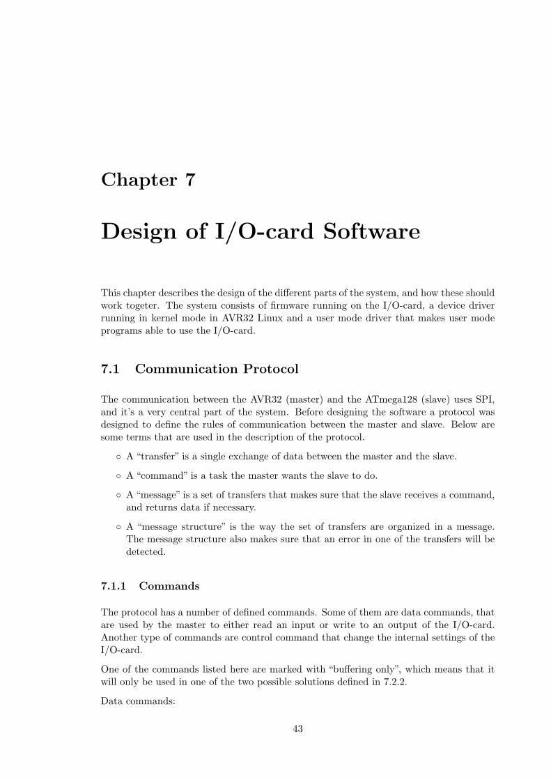
Chapter 7
Design of I/O-card Software
This chapter describes the design of the different parts of the system, and how these shouldwork togeter. The system consists of firmware running on the I/O-card, a device driverrunning in kernel mode in AVR32 Linux and a user mode driver that makes user modeprograms able to use the I/O-card.
7.1 Communication Protocol
The communication between the AVR32 (master) and the ATmega128 (slave) uses SPI,and it’s a very central part of the system. Before designing the software a protocol wasdesigned to define the rules of communication between the master and slave. Below aresome terms that are used in the description of the protocol.
A “transfer” is a single exchange of data between the master and the slave.
A “command” is a task the master wants the slave to do.
A “message” is a set of transfers that makes sure that the slave receives a command,and returns data if necessary.
A “message structure” is the way the set of transfers are organized in a message.The message structure also makes sure that an error in one of the transfers will bedetected.
7.1.1 Commands
The protocol has a number of defined commands. Some of them are data commands, thatare used by the master to either read an input or write to an output of the I/O-card.Another type of commands are control command that change the internal settings of theI/O-card.
One of the commands listed here are marked with “buffering only”, which means that itwill only be used in one of the two possible solutions defined in 7.2.2.
Data commands:
43
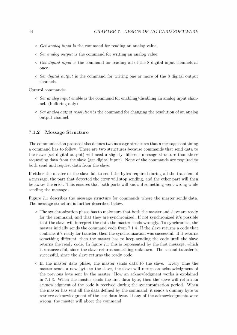
44 CHAPTER 7. DESIGN OF I/O-CARD SOFTWARE
Get analog input is the command for reading an analog value.
Set analog output is the command for writing an analog value.
Get digital input is the command for reading all of the 8 digital input channels atonce.
Set digital output is the command for writing one or more of the 8 digital outputchannels.
Control commands:
Set analog input enable is the command for enabling/disabling an analog input chan-nel. (buffering only)
Set analog output resolution is the command for changing the resolution of an analogoutput channel.
7.1.2 Message Structure
The communication protocol also defines two message structures that a message containinga command has to follow. There are two structures because commands that send data tothe slave (set digital output) will need a slightly different message structure than thoserequesting data from the slave (get digital input). None of the commands are required toboth send and request data from the slave.
If either the master or the slave fail to send the bytes required during all the transfers ofa message, the part that detected the error will stop sending, and the other part will thenbe aware the error. This ensures that both parts will know if something went wrong whilesending the message.
Figure 7.1 describes the message structure for commands where the master sends data.The message structure is further described below.
The synchronization phase has to make sure that both the master and slave are readyfor the command, and that they are synchronized. If not synchronized it’s possiblethat the slave will interpret the data the master sends wrongly. To synchronize, themaster initially sends the command code from 7.1.4. If the slave returns a code thatconfirms it’s ready for transfer, then the synchronization was successful. If it returnssomething different, then the master has to keep sending the code until the slavereturns the ready code. In figure 7.1 this is represented by the first message, whichis unsuccessful, since the slave returns something unknown. The second transfer issuccessful, since the slave returns the ready code.
In the master data phase, the master sends data to the slave. Every time themaster sends a new byte to the slave, the slave will return an acknowledgment ofthe previous byte sent by the master. How an acknowledgment works is explainedin 7.1.3. When the master sends the first data byte, then the slave will return anacknowledgment of the code it received during the synchronization period. Whenthe master has sent all the data defined by the command, it sends a dummy byte toretrieve acknowledgment of the last data byte. If any of the acknowledgments werewrong, the master will abort the command.
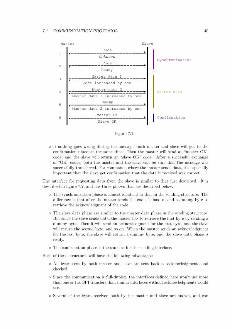
7.1. COMMUNICATION PROTOCOL 45
Figure 7.1:
If nothing goes wrong during the message, both master and slave will get to theconfirmation phase at the same time. Then the master will send an “master OK”code, and the slave will return an “slave OK” code. After a successful exchangeof “OK” codes, both the master and the slave can be sure that the message wassuccessfully transferred. For commands where the master sends data, it’s especiallyimportant that the slave get confirmation that the data it received was correct.
The interface for requesting data from the slave is similar to that just described. It isdescribed in figure 7.2, and has three phases that are described below:
The synchronization phase is almost identical to that in the sending structure. Thedifference is that after the master sends the code, it has to send a dummy byte toretrieve the acknowledgment of the code.
The slave data phase are similar to the master data phase in the sending structure.But since the slave sends data, the master has to retrieve the first byte by sending adummy byte. Then it will send an acknowledgment for the first byte, and the slavewill return the second byte, and so on. When the master sends an acknowledgmentfor the last byte, the slave will return a dummy byte, and the slave data phase isready.
The confirmation phase is the same as for the sending interface.
Both of these structures will have the following advantages:
All bytes sent by both master and slave are sent back as acknowledgments andchecked.
Since the communication is full-duplex, the interfaces defined here won’t use morethan one or two SPI transfers than similar interfaces without acknowledgments woulduse.
Several of the bytes received both by the master and slave are known, and can
46 CHAPTER 7. DESIGN OF I/O-CARD SOFTWARE
Figure 7.2:
therefor be checked for errors.
7.1.3 Acknowledgments
When either the master or the slave receives data, they will return an acknowledgmentduring the next transfer as explained in 7.1.2. This is to detect errors that either breaksthe synchronization between the master and the slave, or errors during transfer of data.
To be able to tell if the correct data was received, the acknowledgment returns the receiveddata back the the sender. The natural choice would be that the acknowledgment wouldhave the same value as the original data. This proved to be a bad idea, because of the waySPI works. SPI uses one data register for both sending and receiving. If this register isn’tdeleted after a transfer, the previously received byte will be sent during the next transfer.This means that an acknowledgment consisting of the original data would fail. Thereforethe acknowledgment is always the original byte increased by one. If the original byte hadthe value 255, then the acknowledgment would be zero.
7.1.4 SPI codes
Each message begins with the master sending a code to the slave. This code tells theslave what kind of command the message contain, and information about channel andsubchannel if needed. The code consists of 1 byte (8 bits), where the first 5 bits arereserved for identifying the command, and the last three bits are for identifying channelsand subchannels. The header file spiByteCodes.h below has constants and macros for
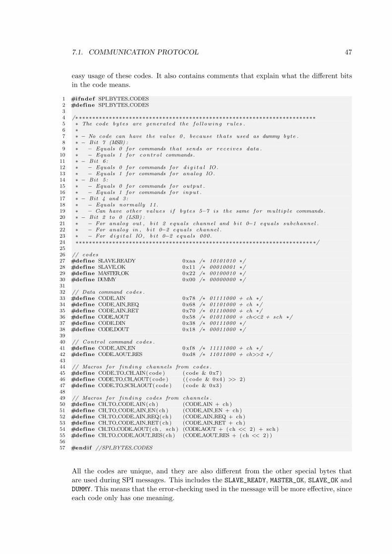
7.1. COMMUNICATION PROTOCOL 47
easy usage of these codes. It also contains comments that explain what the different bitsin the code means.
1 #ifndef SPI BYTES CODES2 #define SPI BYTES CODES34 /∗ ∗∗∗∗∗∗∗∗∗∗∗∗∗∗∗∗∗∗∗∗∗∗∗∗∗∗∗∗∗∗∗∗∗∗∗∗∗∗∗∗∗∗∗∗∗∗∗∗∗∗∗∗∗∗∗∗∗∗∗∗∗∗∗∗∗∗∗∗∗∗∗5 ∗ The code by t e s are generated the f o l l ow i n g ru l e s .6 ∗7 ∗ − No code can have the va lue 0 , because t h a t s used as dummy by te .8 ∗ − Bit 7 (MSB) :9 ∗ − Equals 0 f o r commands tha t sends or r e c e i v e s data .
10 ∗ − Equals 1 f o r con t ro l commands .11 ∗ − Bit 6 :12 ∗ − Equals 0 f o r commands fo r d i g i t a l IO .13 ∗ − Equals 1 f o r commands fo r analog IO .14 ∗ − Bit 5 :15 ∗ − Equals 0 f o r commands fo r output .16 ∗ − Equals 1 f o r commands fo r input .17 ∗ − Bit 4 and 3:18 ∗ − Equals normal ly 11.19 ∗ − Can have other va lue s i f b y t e s 5−7 i s the same fo r mu l t i p l e commands .20 ∗ − Bit 2 to 0 (LSB) :21 ∗ − For analog out , b i t 2 equa l s channel and b i t 0−1 equa l s subchannel .22 ∗ − For analog in , b i t 0−2 equa l s channel .23 ∗ − For d i g i t a l IO , b i t 0−2 equa l s 000.24 ∗∗∗∗∗∗∗∗∗∗∗∗∗∗∗∗∗∗∗∗∗∗∗∗∗∗∗∗∗∗∗∗∗∗∗∗∗∗∗∗∗∗∗∗∗∗∗∗∗∗∗∗∗∗∗∗∗∗∗∗∗∗∗∗∗∗∗∗∗∗∗ ∗/2526 // codes27 #define SLAVE READY 0xaa /∗ 10101010 ∗/28 #define SLAVE OK 0x11 /∗ 00010001 ∗/29 #define MASTER OK 0x22 /∗ 00100010 ∗/30 #define DUMMY 0x00 /∗ 00000000 ∗/3132 // Data command codes .33 #define CODE AIN 0x78 /∗ 01111000 + ch ∗/34 #define CODE AIN REQ 0x68 /∗ 01101000 + ch ∗/35 #define CODE AIN RET 0x70 /∗ 01110000 + ch ∗/36 #define CODE AOUT 0x58 /∗ 01011000 + ch<<2 + sch ∗/37 #define CODE DIN 0x38 /∗ 00111000 ∗/38 #define CODE DOUT 0x18 /∗ 00011000 ∗/3940 // Control command codes .41 #define CODE AIN EN 0 xf8 /∗ 11111000 + ch ∗/42 #define CODE AOUT RES 0xd8 /∗ 11011000 + ch>>2 ∗/4344 // Macros f o r f i nd in g channels from codes .45 #define CODE TO CH AIN( code ) ( code & 0x7 )46 #define CODE TO CH AOUT( code ) ( ( code & 0x4 ) >> 2)47 #define CODE TO SCH AOUT( code ) ( code & 0x3 )4849 // Macros f o r f i nd in g codes from channels .50 #define CH TO CODE AIN( ch ) (CODE AIN + ch )51 #define CH TO CODE AIN EN( ch ) (CODE AIN EN + ch )52 #define CH TO CODE AIN REQ( ch ) (CODE AIN REQ + ch )53 #define CH TO CODE AIN RET( ch ) (CODE AIN RET + ch )54 #define CH TO CODE AOUT( ch , sch ) (CODE AOUT + ( ch << 2) + sch )55 #define CH TO CODE AOUT RES( ch ) (CODE AOUT RES + ( ch << 2) )5657 #endif //SPI BYTES CODES
All the codes are unique, and they are also different from the other special bytes thatare used during SPI messages. This includes the SLAVE_READY, MASTER_OK, SLAVE_OK andDUMMY. This means that the error-checking used in the message will be more effective, sinceeach code only has one meaning.
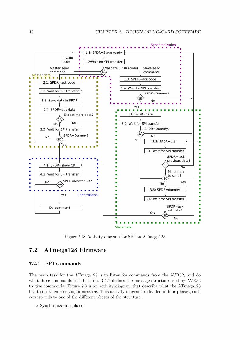
48 CHAPTER 7. DESIGN OF I/O-CARD SOFTWARE
Figure 7.3: Activity diagram for SPI on ATmega128
7.2 ATmega128 Firmware
7.2.1 SPI commands
The main task for the ATmega128 is to listen for commands from the AVR32, and dowhat these commands tells it to do. 7.1.2 defines the message structure used by AVR32to give commands. Figure 7.3 is an activity diagram that describe what the ATmega128has to do when receiving a message. This activity diagram is divided in four phases, eachcorresponds to one of the different phases of the structure.
Synchronization phase
7.2. ATMEGA128 FIRMWARE 49
• Activity 1.1 sets the SPI data register (SPDR) to the “Slave ready” code. Thedata in this register will be sends to the master during the next SPI transfer.
• Activity 1.2 waits until the next SPI transfer.
• Decision point 1A validates the received data, and check if it’s one of the codesdefined in 7.1.4. This code tells the slave what kind of command the messagecontains. Depending on the type of message, the next activity will either be1.3 (slave sends) or 2.1 (master sends).
• Activity 1.3 sets the SPI data register to an acknowledgment of the code.
• Activity 1.4 waits until the next SPI transfer.
• Decision point 1B checks if the received byte is a dummy byte. No dummy bytemeans that the message failed.
Master data phase
• Activity 2.1 sets the SPI data register to an acknowledgment of the code.
• Activity 2.2 waits until the next SPI transfer.
• Activity 2.3 saves the received data in the appropriate variable.
• Activity 2.4 sets the SPI data register to an acknowledgment of the receiveddata.
• Decision point 2A checks if the slave expects more data. The slave knows this,because the number of data bytes are always the same for the same type ofcommand. Further, the type of command is known because of the code.
• Activity 2.5 waits until the next SPI transfer.
• Decision point 2B checks if the received data was a dummy byte. No dummybyte means that receiving the message failed.
Slave data phase
• Activity 3.1 sets the SPI data register to the first data the slave wants to send.
• Activity 3.2 waits until the next SPI transfer.
• Decision point 3A checks if the received data was a dummy byte. No dummybyte means that receiving the message failed.
• Decision point 3C checks if there is more data that should be sent, as in themaster data phase, the number of bytes is defined by the type of command.
• Activity 3.3 sets the SPI data register to the next data the slave wants to send.
• Activity 3.4 waits until the next SPI transfer.
• Decision point 3B checks if the received data was an acknowledgment of the datathe slave sent during the transfer before the recent transfer. No acknowledgmentmeans that receiving the message failed.
• Activity 3.5 sets the SPI data register to be a dummy byte, since no data shouldbe sent from the slave during the next transfer.
50 CHAPTER 7. DESIGN OF I/O-CARD SOFTWARE
• Activity 3.6 waits until the next SPI transfer.
• Decision point 3D checks if the received data was an acknowledgment of thelast data the slave sent. No acknowledgment means that receiving the messagefailed.
Confirmation phase
• Activity 4.1 sets the SPI data register to the “Slave OK” code. This tells themaster that the slave didn’t discover any errors during the message.
• Activity 4.2 waits until the next SPI transfer.
• Decision point 4A checks if the received data is the “Master OK” code, whichwill confirm that the message was sent without errors.
7.2.2 Analog Input
The analog to digital conversion inside the ATmega128 is an operation that takes 13ADC clock cycles. The ADC clock has to be between 50kHz and 200kHz, to do a 10bits conversion. By using a prescaler of 128 the ADC will get a frequency calculatedin equation 7.1. With this frequency an ADC conversion will take 104µs as shown inequation 7.2 and 7.3. This means that the ADC conversion will take a considerableamount of time, and the ATmega128 will not be able to do the conversion during a SPImessage if the AVR32 doesn’t wait for it.
fADC =fµC
128= 125kHz (7.1)
TADC =1
fADC= 8µs (7.2)
Tconversion = 13 ∗ TADC = 104µs (7.3)
To solve this problem, two solutions were developed. The first solution is to use interrupts.This is normally the best way to solve problems when a processor has to wait while another(often I/O) computer component completes its task. When the task is completed aninterrupt is sent to the processor, and the it can retrieve the result.
The second solution is to let the ATmega128 know which analog input channels that arein use. It can then continuously convert the analog values of these channels into digitalvalues and store them in a buffer in memory. When the master wants to read an analoginput channel, the slave can just return the previously converted result. This solution ispossible to use, since the analog to digital conversion is a separate part of the ATmega128.Meaning that the normal code will continue to run as usual during the analog conversion.The only overhead is saving the results and start new conversions.
The two solutions, called interrupt mode and buffering mode, will both work, but havesome different advantages, shown below.
Interrupt mode will always return a newly converted result, while buffering modemay return an older result.
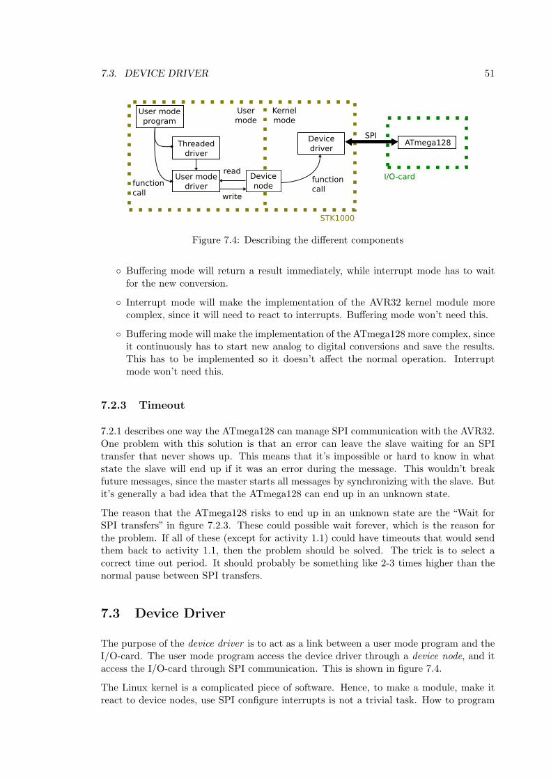
7.3. DEVICE DRIVER 51
Figure 7.4: Describing the different components
Buffering mode will return a result immediately, while interrupt mode has to waitfor the new conversion.
Interrupt mode will make the implementation of the AVR32 kernel module morecomplex, since it will need to react to interrupts. Buffering mode won’t need this.
Buffering mode will make the implementation of the ATmega128 more complex, sinceit continuously has to start new analog to digital conversions and save the results.This has to be implemented so it doesn’t affect the normal operation. Interruptmode won’t need this.
7.2.3 Timeout
7.2.1 describes one way the ATmega128 can manage SPI communication with the AVR32.One problem with this solution is that an error can leave the slave waiting for an SPItransfer that never shows up. This means that it’s impossible or hard to know in whatstate the slave will end up if it was an error during the message. This wouldn’t breakfuture messages, since the master starts all messages by synchronizing with the slave. Butit’s generally a bad idea that the ATmega128 can end up in an unknown state.
The reason that the ATmega128 risks to end up in an unknown state are the “Wait forSPI transfers” in figure 7.2.3. These could possible wait forever, which is the reason forthe problem. If all of these (except for activity 1.1) could have timeouts that would sendthem back to activity 1.1, then the problem should be solved. The trick is to select acorrect time out period. It should probably be something like 2-3 times higher than thenormal pause between SPI transfers.
7.3 Device Driver
The purpose of the device driver is to act as a link between a user mode program and theI/O-card. The user mode program access the device driver through a device node, and itaccess the I/O-card through SPI communication. This is shown in figure 7.4.
The Linux kernel is a complicated piece of software. Hence, to make a module, make itreact to device nodes, use SPI configure interrupts is not a trivial task. How to program
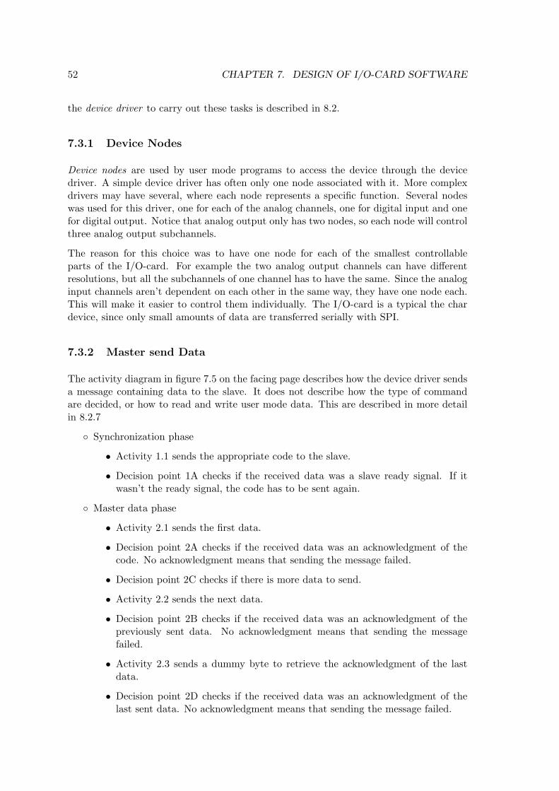
52 CHAPTER 7. DESIGN OF I/O-CARD SOFTWARE
the device driver to carry out these tasks is described in 8.2.
7.3.1 Device Nodes
Device nodes are used by user mode programs to access the device through the devicedriver. A simple device driver has often only one node associated with it. More complexdrivers may have several, where each node represents a specific function. Several nodeswas used for this driver, one for each of the analog channels, one for digital input and onefor digital output. Notice that analog output only has two nodes, so each node will controlthree analog output subchannels.
The reason for this choice was to have one node for each of the smallest controllableparts of the I/O-card. For example the two analog output channels can have differentresolutions, but all the subchannels of one channel has to have the same. Since the analoginput channels aren’t dependent on each other in the same way, they have one node each.This will make it easier to control them individually. The I/O-card is a typical the chardevice, since only small amounts of data are transferred serially with SPI.
7.3.2 Master send Data
The activity diagram in figure 7.5 on the facing page describes how the device driver sendsa message containing data to the slave. It does not describe how the type of commandare decided, or how to read and write user mode data. This are described in more detailin 8.2.7
Synchronization phase
• Activity 1.1 sends the appropriate code to the slave.
• Decision point 1A checks if the received data was a slave ready signal. If itwasn’t the ready signal, the code has to be sent again.
Master data phase
• Activity 2.1 sends the first data.
• Decision point 2A checks if the received data was an acknowledgment of thecode. No acknowledgment means that sending the message failed.
• Decision point 2C checks if there is more data to send.
• Activity 2.2 sends the next data.
• Decision point 2B checks if the received data was an acknowledgment of thepreviously sent data. No acknowledgment means that sending the messagefailed.
• Activity 2.3 sends a dummy byte to retrieve the acknowledgment of the lastdata.
• Decision point 2D checks if the received data was an acknowledgment of thelast sent data. No acknowledgment means that sending the message failed.
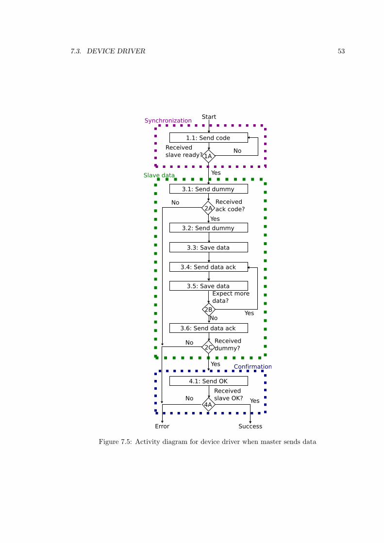
7.3. DEVICE DRIVER 53
Figure 7.5: Activity diagram for device driver when master sends data
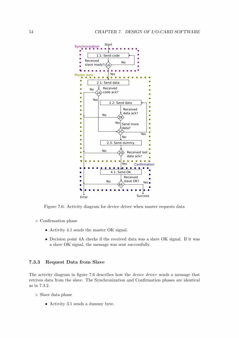
54 CHAPTER 7. DESIGN OF I/O-CARD SOFTWARE
Figure 7.6: Activity diagram for device driver when master requests data
Confirmation phase
• Activity 4.1 sends the master OK signal.
• Decision point 4A checks if the received data was a slave OK signal. If it wasa slave OK signal, the message was sent successfully.
7.3.3 Request Data from Slave
The activity diagram in figure 7.6 describes how the device driver sends a message thatretrives data from the slave. The Synchronization and Confirmation phases are identicalas in 7.3.2.
Slave data phase
• Activity 3.1 sends a dummy byte.
7.4. USER MODE DRIVER 55
• Decision point 2A checks if the received data was an acknowledgment of thecode. No acknowledgment means that sending the message failed.
• Activity 3.2 sends a new dummy byte.
• Activity 3.3 saves the received data.
• Activity 3.4 sends an acknowledgment of the received data.
• Decision point 2B checks if more data is expected.
• Activity 3.6 sends an acknowledgment of the last received data.
• Decision point 2C checks if the received data was a dummy byte. No dummybyte means that sending the message failed.
7.4 User Mode Driver
Each of the commands that can be given to the I/O-card have one or more functionsprovided by the user mode driver. These functions makes it possible to give the I/O-cardscommands just with a single function call, and this function call should return the resultof the message. This will make it very easy to use the different features of the I/O-card.The reason that some commands should have more than one function, is that they can beused in different ways. The user mode driver should have the following functionality:
Read from different analog in channels.
Write values to different analog out channels.
Read all digital in channels at once.
Write to all or a chosen number of the digital out channels.
Change different properties of the I/O card, like analog resolution or enable/disablefunctionality.
7.5 Threaded User Mode Driver
Since communicating with I/O often includes waiting, commands are often executed inthreads. To make this possible, another layer of software was used on top of the user modedriver. This layer uses threads to send and receive data from the I/O-card, making thetotal system more effective. This has only been designed for analog I/O.
7.5.1 Threaded Analog Input
The analog input uses threads to sample the analog input values. Each channel has itsown periodic thread that gets an analog input value and store it in a buffer. When a usermode application needs the value of an analog channel, it can quickly get the bufferedvalue.
56 CHAPTER 7. DESIGN OF I/O-CARD SOFTWARE
This solution works best when the I/O-card uses interrupt mode, since the value the threadis putting into a buffer should be as new as possible. If using buffering mode, the datawill be buffered twice, and this should be avoided. The main disadvantage of interruptmode is that the command takes longer time, is less of a problem when it’s performed bya thread. It will not slow down the rest of the program.
7.5.2 Threaded Analog Output
The analog output uses a worker thread. This thread waits until it receives an analogoutput command from the main thread. Then it executes this command and waits for thenext. This means that the main thread gives a short command to the worker thread, andthen it can continue executing the rest of its code.
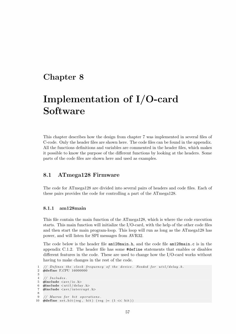
Chapter 8
Implementation of I/O-cardSoftware
This chapter describes how the design from chapter 7 was implemented in several files ofC-code. Only the header files are shown here. The code files can be found in the appendix.All the functions definitions and variables are commented in the header files, which makesit possible to know the purpose of the different functions by looking at the headers. Someparts of the code files are shown here and used as examples.
8.1 ATmega128 Firmware
The code for ATmega128 are divided into several pairs of headers and code files. Each ofthese pairs provides the code for controlling a part of the ATmega128.
8.1.1 am128main
This file contain the main function of the ATmega128, which is where the code executionstarts. This main function will initialize the I/O-card, with the help of the other code filesand then start the main program-loop. This loop will run as long as the ATmega128 haspower, and will listen for SPI messages from AVR32.
The code below is the header file am128main.h, and the code file am128main.c is in theappendix C.1.2. The header file has some #define statements that enables or disablesdifferent features in the code. These are used to change how the I/O-card works withouthaving to make changes in the rest of the code.
1 // Def ines the c l o ck frequency o f the dev i ce . Needed fo r u t i l / de lay . h .2 #define F CPU 1600000034 // Inc ludes .5 #include <avr / i o . h>6 #include <u t i l / de lay . h>7 #include <avr / i n t e r r up t . h>89 // Macros f o r b i t opera t ions .
10 #define s e t b i t ( reg , b i t ) ( reg |= (1 << b i t ) )
57
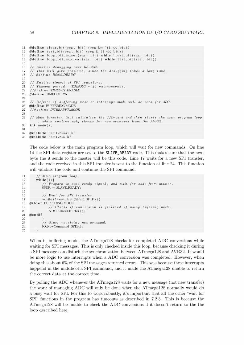
58 CHAPTER 8. IMPLEMENTATION OF I/O-CARD SOFTWARE
11 #define c l e a r b i t ( reg , b i t ) ( reg &= ˜(1 << b i t ) )12 #define t e s t b i t ( reg , b i t ) ( reg & (1 << b i t ) )13 #define l o o p b i t i s s e t ( reg , b i t ) while ( ! t e s t b i t ( reg , b i t ) )14 #define l o o p b i t i s c l e a r ( reg , b i t ) while ( t e s t b i t ( reg , b i t ) )1516 // Enables debugging over RS−232.17 // This w i l l g i v e problems , s ince the debugging take s a long time .18 // #de f ine RS232 DEBUG1920 // Enables t imout o f SPI t r an s f e r s .21 // Timeout per iod = TIMEOUT ∗ 20 microseconds .22 //#de f ine TIMEOUT ENABLE23 #define TIMEOUT 252425 // Def ines i f b u f f e r i n g mode or i n t e r r up t mode w i l l be used f o r ADC.26 #define BUFFERING MODE27 //#de f ine INTERRUPT MODE2829 // Main func t ion tha t i n i t i a l i z e the I /O−card and then s t a r t s the main program loop
, which cont inuous l y checks f o r new messages from the AVR32.30 int main ( ) ;3132 #include ”am128uart . h”33 #include ”am128io . h”
The code below is the main program loop, which will wait for new commands. On line14 the SPI data register are set to the SLAVE_READY code. This makes sure that the nextbyte the it sends to the master will be this code. Line 17 waits for a new SPI transfer,and the code received in this SPI transfer is sent to the function at line 24. This functionwill validate the code and continue the SPI command.
11 // Main program loop .12 while (1 ) 13 // Prepare to send ready s i gna l , and wait f o r code from master .14 SPDR = SLAVE READY;1516 // Wait f o r SPI t r an s f e r .17 while ( ! t e s t b i t (SPSR, SPIF) ) 18 #ifdef BUFFERING MODE19 // Checks i f convers ion i s f i n i s h e d i f us ing bu f e r ing mode .20 ADC CheckBuffer ( ) ;21 #endif22 23 // S tar t r e c e i v i n g new command .24 IO NewCommand(SPDR) ;25
When in buffering mode, the ATmega128 checks for completed ADC conversions whilewaiting for SPI messages. This is only checked inside this loop, because checking it duringa SPI message can disturb the synchronization between ATmega128 and AVR32. It wouldbe more logic to use interrupts when a ADC conversion was completed. However, whendoing this about 6% of the SPI messages returned errors. This was because these interruptshappend in the middle of a SPI command, and it made the ATmega128 unable to returnthe correct data at the correct time.
By polling the ADC whenever the ATmega128 waits for a new message (not new transfer)the work of managing ADC will only be done when the ATmega128 normally would doa busy wait for SPI. For this to work robustly, it’s important that all the other “wait forSPI” functions in the program has timeouts as described in 7.2.3. This is because theATmega128 will be unable to check the ADC conversions if it doesn’t return to the theloop described here.
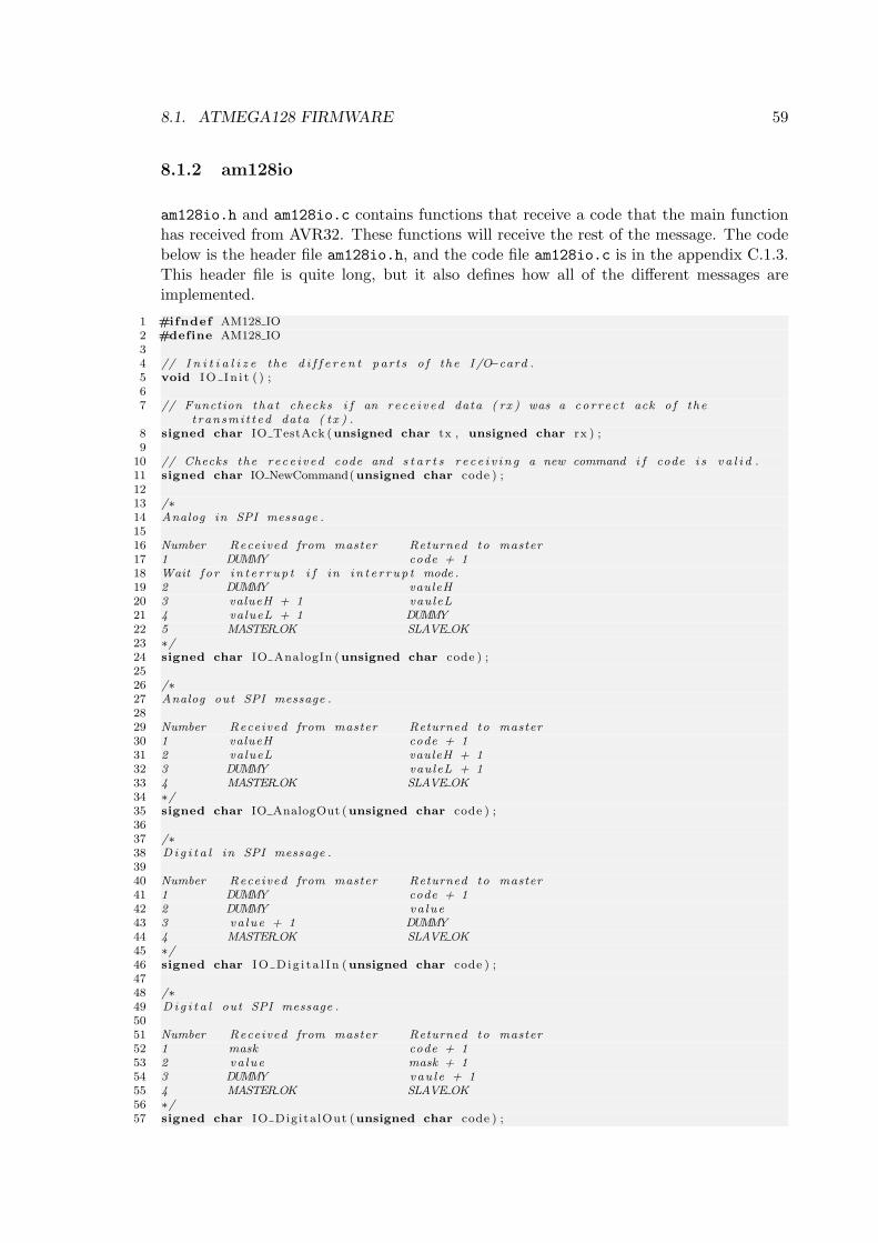
8.1. ATMEGA128 FIRMWARE 59
8.1.2 am128io
am128io.h and am128io.c contains functions that receive a code that the main functionhas received from AVR32. These functions will receive the rest of the message. The codebelow is the header file am128io.h, and the code file am128io.c is in the appendix C.1.3.This header file is quite long, but it also defines how all of the different messages areimplemented.
1 #ifndef AM128 IO2 #define AM128 IO34 // I n i t i a l i z e the d i f f e r e n t par t s o f the I /O−card .5 void IO In i t ( ) ;67 // Function tha t checks i f an rece i v ed data ( rx ) was a cor r ec t ack o f the
t ransmi t t ed data ( t x ) .8 signed char IO TestAck (unsigned char tx , unsigned char rx ) ;9
10 // Checks the rece i v ed code and s t a r t s r e c e i v i n g a new command i f code i s v a l i d .11 signed char IO NewCommand(unsigned char code ) ;1213 /∗14 Analog in SPI message .1516 Number Received from master Returned to master17 1 DUMMY code + 118 Wait f o r i n t e r r up t i f in i n t e r r up t mode .19 2 DUMMY vauleH20 3 valueH + 1 vauleL21 4 valueL + 1 DUMMY22 5 MASTER OK SLAVE OK23 ∗/24 signed char IO AnalogIn (unsigned char code ) ;2526 /∗27 Analog out SPI message .2829 Number Received from master Returned to master30 1 valueH code + 131 2 valueL vauleH + 132 3 DUMMY vauleL + 133 4 MASTER OK SLAVE OK34 ∗/35 signed char IO AnalogOut (unsigned char code ) ;3637 /∗38 Di g i t a l in SPI message .3940 Number Received from master Returned to master41 1 DUMMY code + 142 2 DUMMY va lue43 3 va lue + 1 DUMMY44 4 MASTER OK SLAVE OK45 ∗/46 signed char IO Dig i t a l In (unsigned char code ) ;4748 /∗49 Di g i t a l out SPI message .5051 Number Received from master Returned to master52 1 mask code + 153 2 va lue mask + 154 3 DUMMY vau le + 155 4 MASTER OK SLAVE OK56 ∗/57 signed char IO Digita lOut (unsigned char code ) ;
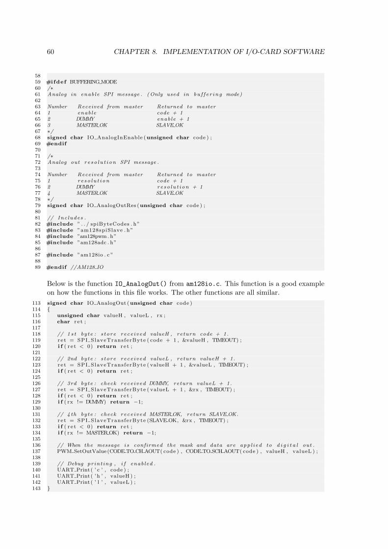
60 CHAPTER 8. IMPLEMENTATION OF I/O-CARD SOFTWARE
5859 #ifdef BUFFERING MODE60 /∗61 Analog in enab le SPI message . (Only used in b u f f e r i n g mode)6263 Number Received from master Returned to master64 1 enab le code + 165 2 DUMMY enab le + 166 3 MASTER OK SLAVE OK67 ∗/68 signed char IO AnalogInEnable (unsigned char code ) ;69 #endif7071 /∗72 Analog out r e s o l u t i on SPI message .7374 Number Received from master Returned to master75 1 r e s o l u t i on code + 176 2 DUMMY re so l u t i on + 177 4 MASTER OK SLAVE OK78 ∗/79 signed char IO AnalogOutRes (unsigned char code ) ;8081 // Inc ludes .82 #include ” . . / spiByteCodes . h”83 #include ”am128spiSlave . h”84 #include ”am128pwm. h”85 #include ”am128adc . h”8687 #include ”am128io . c ”8889 #endif //AM128 IO
Below is the function IO_AnalogOut() from am128io.c. This function is a good exampleon how the functions in this file works. The other functions are all similar.
113 signed char IO AnalogOut (unsigned char code )114 115 unsigned char valueH , valueL , rx ;116 char r e t ;117118 // 1 s t by te : s t o r e r ece i v ed valueH , re turn code + 1.119 r e t = SPI SlaveTrans ferByte ( code + 1 , &valueH , TIMEOUT) ;120 i f ( r e t < 0) return r e t ;121122 // 2nd by te : s t o r e r ece i v ed valueL , re turn valueH + 1.123 r e t = SPI SlaveTrans ferByte ( valueH + 1 , &valueL , TIMEOUT) ;124 i f ( r e t < 0) return r e t ;125126 // 3rd by te : check rece i v ed DUMMY, return valueL + 1.127 r e t = SPI SlaveTrans ferByte ( valueL + 1 , &rx , TIMEOUT) ;128 i f ( r e t < 0) return r e t ;129 i f ( rx != DUMMY) return −1;130131 // 4 th by te : check rece i v ed MASTER OK, return SLAVE OK.132 r e t = SPI SlaveTrans ferByte (SLAVE OK, &rx , TIMEOUT) ;133 i f ( r e t < 0) return r e t ;134 i f ( rx != MASTER OK) return −1;135136 // When the message i s confirmed the mask and data are app l i ed to d i g i t a l out .137 PWM SetOutValue(CODE TO CH AOUT( code ) , CODE TO SCH AOUT( code ) , valueH , valueL ) ;138139 // Debug pr in t ing , i f enab led .140 UART Print ( ’ c ’ , code ) ;141 UART Print ( ’h ’ , valueH ) ;142 UART Print ( ’ l ’ , valueL ) ;143
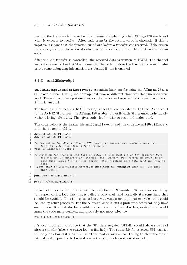
8.1. ATMEGA128 FIRMWARE 61
Each of the transfers is marked with a comment explaining what ATmega128 sends andwhat it expects to receive. After each transfer the return value is checked. If this isnegative it means that the function timed out before a transfer was received. If the returnvalue is negative or the received data wasn’t the expected data, the function returns anerror.
After the 4th transfer is controlled, the received data is written to PWM. The channeland subchannel of the PWM is defined by the code. Before the function returns, it alsoprints some debugging information via UART, if this is enabled.
8.1.3 am128slaveSpi
am128slaveSpi.h and am128slaveSpi.c contain functions for using the ATmega128 as aSPI slave device. During the development several different slave transfer functions wereused. The end result was just one function that sends and receive one byte and has timeoutif this is enabled.
The functions that receives the SPI messages does this one transfer at the time. As opposedto the AVR32 SPI driver, the ATmega128 is able to handle each SPI transfer individuallywithout losing effectivity. This gives code that’s easier to read and understand.
The code below is the header file am128spiSlave.h, and the code file am128spiSlave.cis in the appendix C.1.4.
1 #ifndef AM128 SPI SLAVE2 #define AM128 SPI SLAVE34 // I n i t i a l i z e the ATmega128 as a SPI s l a v e . I f t imeout are enabled , then t h i s
func t i on w i l l i n i t i a l i z e a timer a swe l l .5 void SPI S l ave In i t (void ) ;67 // Function fo r t r an s f e r one by te o f data . I t w i l l wai t f o r an SPI t r an s f e r from
the master . I f t imeouts are enabled , the func t i on w i l l re turn an error a f t e rsome time . Since SPI i s f u l l y duplex , t h i s func t i on w i l l both send and re c e i v edata .
8 signed char SPI SlaveTrans ferByte (unsigned char tx , unsigned char ∗ rx , unsignedchar usec ) ;
910 #include ”am128spiSlave . c ”1112 #endif //AM128 SPI SLAVE
Below is the while loop that is used to wait for a SPI transfer. To wait for somethingto happen with a loop like this, is called a busy-wait, and normally it’s something thatshould be avoided. This is because a busy-wait wastes many processor cycles that couldbe used by other processes. For the ATmega128 this isn’t a problem since it can only haveone process. It would also be possible to use interrupts instead of busy-wait, but it wouldmake the code more complex and probably not more effective.while ( ! ( SPSR & (1<<SPIF) ) )
It’s also important to notice that the SPI data register (SPDR) should always be readafter a transfer (after the while loop is finished). The status bit for received SPI transferwill only be cleared if the SPDR is either read or written to. Failing to clear the statusbit makes it impossible to know if a new transfer has been received or not.
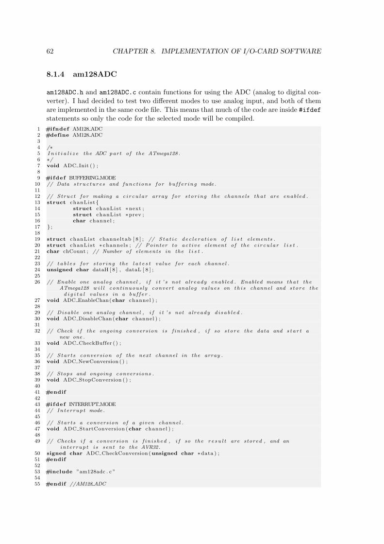
62 CHAPTER 8. IMPLEMENTATION OF I/O-CARD SOFTWARE
8.1.4 am128ADC
am128ADC.h and am128ADC.c contain functions for using the ADC (analog to digital con-verter). I had decided to test two different modes to use analog input, and both of themare implemented in the same code file. This means that much of the code are inside #ifdefstatements so only the code for the selected mode will be compiled.
1 #ifndef AM128 ADC2 #define AM128 ADC34 /∗5 I n i t i a l i z e the ADC part o f the ATmega128 .6 ∗/7 void ADC Init ( ) ;89 #ifdef BUFFERING MODE
10 // Data s t r u c t u r e s and func t i ons f o r b u f f e r i n g mode .1112 // S t ruc t f o r making a c i r c u l a r array f o r s t o r i n g the channels t ha t are enab led .13 struct chanList 14 struct chanList ∗next ;15 struct chanList ∗prev ;16 char channel ;17 ;1819 struct chanList channeltab [ 8 ] ; // S t a t i c d e c l e r a t i on o f l i s t e lements .20 struct chanList ∗ channe l s ; // Pointer to a c t i v e element o f the c i r c u l a r l i s t .21 char chCount ; // Number o f e lements in the l i s t .2223 // t a b l e s f o r s t o r i n g the l a t e s t va lue f o r each channel .24 unsigned char dataH [ 8 ] , dataL [ 8 ] ;2526 // Enable one analog channel , i f i t ’ s not a l ready enab led . Enabled means tha t the
ATmega128 w i l l con t inuous l y conver t analog va lue s on t h i s channel and s t o r e thed i g i t a l va lue s in a b u f f e r .
27 void ADC EnableChan(char channel ) ;2829 // Disab l e one analog channel , i f i t ’ s not a l ready d i s a b l e d .30 void ADC DisableChan (char channel ) ;3132 // Check i f the ongoing convers ion i s f i n i s h ed , i f so s t o r e the data and s t a r t a
new one .33 void ADC CheckBuffer ( ) ;3435 // S ta r t s convers ion o f the next channel in the array .36 void ADC NewConversion ( ) ;3738 // Stops and ongoing convers ions .39 void ADC StopConversion ( ) ;4041 #endif4243 #ifdef INTERRUPT MODE44 // In t e r rup t mode .4546 // S ta r t s a convers ion o f a g iven channel .47 void ADC StartConversion (char channel ) ;4849 // Checks i f a convers ion i s f i n i s h ed , i f so the r e s u l t are s tored , and an
in t e r r up t i s sent to the AVR32.50 signed char ADC CheckConversion (unsigned char ∗data ) ;51 #endif5253 #include ”am128adc . c ”5455 #endif //AM128 ADC
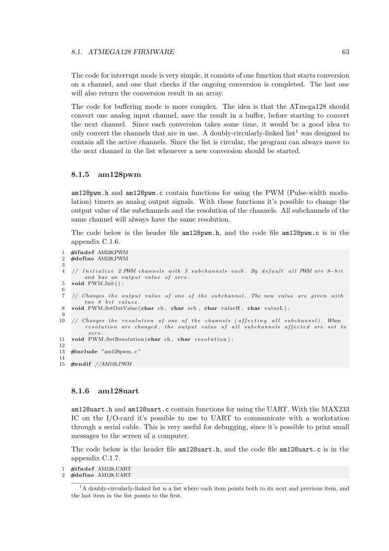
8.1. ATMEGA128 FIRMWARE 63
The code for interrupt mode is very simple, it consists of one function that starts conversionon a channel, and one that checks if the ongoing conversion is completed. The last onewill also return the conversion result in an array.
The code for buffering mode is more complex. The idea is that the ATmega128 shouldconvert one analog input channel, save the result in a buffer, before starting to convertthe next channel. Since each conversion takes some time, it would be a good idea toonly convert the channels that are in use. A doubly-circularly-linked list1 was designed tocontain all the active channels. Since the list is circular, the program can always move tothe next channel in the list whenever a new conversion should be started.
8.1.5 am128pwm
am128pwm.h and am128pwm.c contain functions for using the PWM (Pulse-width modu-lation) timers as analog output signals. With these functions it’s possible to change theoutput value of the subchannels and the resolution of the channels. All subchannels of thesame channel will always have the same resolution.
The code below is the header file am128pwm.h, and the code file am128pwm.c is in theappendix C.1.6.
1 #ifndef AM128 PWM2 #define AM128 PWM34 // I n i t i a l i z e 2 PWM channels with 3 subchanne ls each . By d e f a u l t a l l PWM are 8− b i t
and has an output va lue o f zero .5 void PWM Init ( ) ;67 // Changes the output va lue o f one o f the subchannel . The new va lue are g iven with
two 8 b i t va lue s .8 void PWM SetOutValue(char ch , char sch , char valueH , char valueL ) ;9
10 // Changes the r e s o l u t i on o f one o f the channels ( a f f e c t i n g a l l subchannel ) . Whenr e s o l u t i on are changed , the output va lue o f a l l subchanne ls a f f e c t e d are s e t tozero .
11 void PWM SetResolution (char ch , char r e s o l u t i o n ) ;1213 #include ”am128pwm. c ”1415 #endif //AM128 PWM
8.1.6 am128uart
am128uart.h and am128uart.c contain functions for using the UART. With the MAX233IC on the I/O-card it’s possible to use to UART to communicate with a workstationthrough a serial cable. This is very useful for debugging, since it’s possible to print smallmessages to the screen of a computer.
The code below is the header file am128uart.h, and the code file am128uart.c is in theappendix C.1.7.
1 #ifndef AM128 UART2 #define AM128 UART
1A doubly-circularly-linked list is a list where each item points both to its next and previous item, andthe last item in the list points to the first.
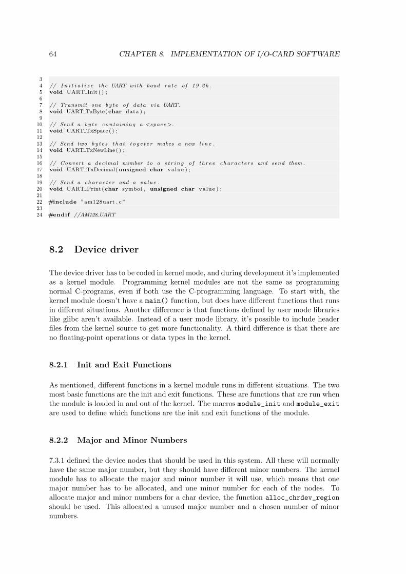
64 CHAPTER 8. IMPLEMENTATION OF I/O-CARD SOFTWARE
34 // I n i t i a l i z e the UART with baud ra te o f 19.2 k .5 void UART Init ( ) ;67 // Transmit one by te o f data v ia UART.8 void UART TxByte(char data ) ;9
10 // Send a by te conta in ing a <space >.11 void UART TxSpace ( ) ;1213 // Send two by t e s t ha t t o g e t e r makes a new l i n e .14 void UART TxNewLine ( ) ;1516 // Convert a decimal number to a s t r i n g o f th ree charac t e r s and send them .17 void UART TxDecimal (unsigned char value ) ;1819 // Send a charac ter and a va lue .20 void UART Print (char symbol , unsigned char value ) ;2122 #include ”am128uart . c ”2324 #endif //AM128 UART
8.2 Device driver
The device driver has to be coded in kernel mode, and during development it’s implementedas a kernel module. Programming kernel modules are not the same as programmingnormal C-programs, even if both use the C-programming language. To start with, thekernel module doesn’t have a main() function, but does have different functions that runsin different situations. Another difference is that functions defined by user mode librarieslike glibc aren’t available. Instead of a user mode library, it’s possible to include headerfiles from the kernel source to get more functionality. A third difference is that there areno floating-point operations or data types in the kernel.
8.2.1 Init and Exit Functions
As mentioned, different functions in a kernel module runs in different situations. The twomost basic functions are the init and exit functions. These are functions that are run whenthe module is loaded in and out of the kernel. The macros module_init and module_exitare used to define which functions are the init and exit functions of the module.
8.2.2 Major and Minor Numbers
7.3.1 defined the device nodes that should be used in this system. All these will normallyhave the same major number, but they should have different minor numbers. The kernelmodule has to allocate the major and minor number it will use, which means that onemajor number has to be allocated, and one minor number for each of the nodes. Toallocate major and minor numbers for a char device, the function alloc_chrdev_regionshould be used. This allocated a unused major number and a chosen number of minornumbers.
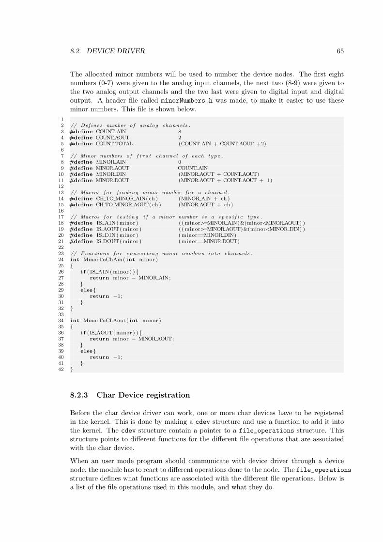
8.2. DEVICE DRIVER 65
The allocated minor numbers will be used to number the device nodes. The first eightnumbers (0-7) were given to the analog input channels, the next two (8-9) were given tothe two analog output channels and the two last were given to digital input and digitaloutput. A header file called minorNumbers.h was made, to make it easier to use theseminor numbers. This file is shown below.
12 // Def ines number o f analog channels .3 #define COUNT AIN 84 #define COUNT AOUT 25 #define COUNT TOTAL (COUNT AIN + COUNT AOUT +2)67 // Minor numbers o f f i r s t channel o f each type .8 #define MINOR AIN 09 #define MINOR AOUT COUNT AIN
10 #define MINOR DIN (MINOR AOUT + COUNT AOUT)11 #define MINOR DOUT (MINOR AOUT + COUNT AOUT + 1)1213 // Macros f o r f i nd in g minor number f o r a channel .14 #define CH TO MINOR AIN( ch ) (MINOR AIN + ch )15 #define CH TO MINOR AOUT( ch ) (MINOR AOUT + ch )1617 // Macros f o r t e s t i n g i f a minor number i s a s p e s i f i c type .18 #define IS AIN ( minor ) ( ( minor>=MINOR AIN)&(minor<MINOR AOUT) )19 #define IS AOUT( minor ) ( ( minor>=MINOR AOUT)&(minor<MINOR DIN) )20 #define IS DIN ( minor ) ( minor==MINOR DIN)21 #define IS DOUT( minor ) ( minor==MINOR DOUT)2223 // Functions f o r conver t ing minor numbers in to channels .24 int MinorToChAin ( int minor )25 26 i f ( IS AIN ( minor ) ) 27 return minor − MINOR AIN;28 29 else 30 return −1;31 32 3334 int MinorToChAout ( int minor )35 36 i f (IS AOUT( minor ) ) 37 return minor − MINOR AOUT;38 39 else 40 return −1;41 42
8.2.3 Char Device registration
Before the char device driver can work, one or more char devices have to be registeredin the kernel. This is done by making a cdev structure and use a function to add it intothe kernel. The cdev structure contain a pointer to a file_operations structure. Thisstructure points to different functions for the different file operations that are associatedwith the char device.
When an user mode program should communicate with device driver through a devicenode, the module has to react to different operations done to the node. The file_operationsstructure defines what functions are associated with the different file operations. Below isa list of the file operations used in this module, and what they do.
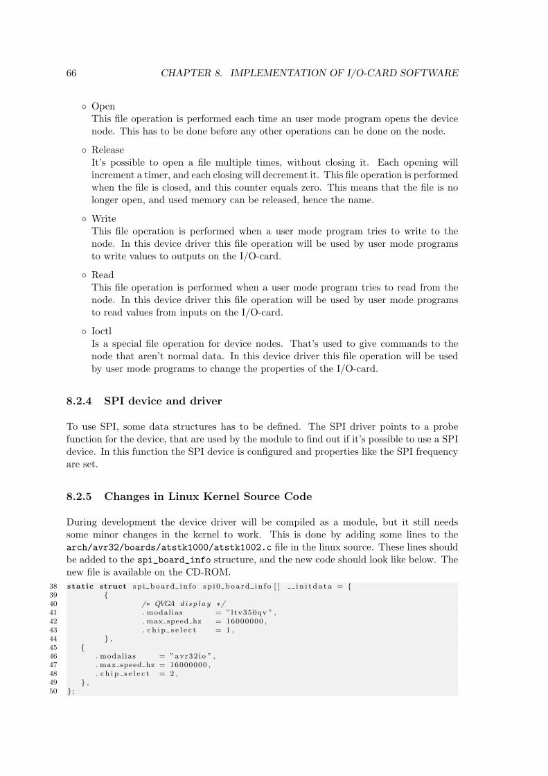
66 CHAPTER 8. IMPLEMENTATION OF I/O-CARD SOFTWARE
OpenThis file operation is performed each time an user mode program opens the devicenode. This has to be done before any other operations can be done on the node.
ReleaseIt’s possible to open a file multiple times, without closing it. Each opening willincrement a timer, and each closing will decrement it. This file operation is performedwhen the file is closed, and this counter equals zero. This means that the file is nolonger open, and used memory can be released, hence the name.
WriteThis file operation is performed when a user mode program tries to write to thenode. In this device driver this file operation will be used by user mode programsto write values to outputs on the I/O-card.
ReadThis file operation is performed when a user mode program tries to read from thenode. In this device driver this file operation will be used by user mode programsto read values from inputs on the I/O-card.
IoctlIs a special file operation for device nodes. That’s used to give commands to thenode that aren’t normal data. In this device driver this file operation will be usedby user mode programs to change the properties of the I/O-card.
8.2.4 SPI device and driver
To use SPI, some data structures has to be defined. The SPI driver points to a probefunction for the device, that are used by the module to find out if it’s possible to use a SPIdevice. In this function the SPI device is configured and properties like the SPI frequencyare set.
8.2.5 Changes in Linux Kernel Source Code
During development the device driver will be compiled as a module, but it still needssome minor changes in the kernel to work. This is done by adding some lines to thearch/avr32/boards/atstk1000/atstk1002.c file in the linux source. These lines shouldbe added to the spi_board_info structure, and the new code should look like below. Thenew file is available on the CD-ROM.
38 stat ic struct s p i b o a r d i n f o s p i 0 boa rd i n f o [ ] i n i t d a t a = 39 40 /∗ QVGA d i s p l a y ∗/41 . modal ias = ”ltv350qv ” ,42 . max speed hz = 16000000 ,43 . c h i p s e l e c t = 1 ,44 ,45 46 . modal ias = ”avr32 io ” ,47 . max speed hz = 16000000 ,48 . c h i p s e l e c t = 2 ,49 ,50 ;
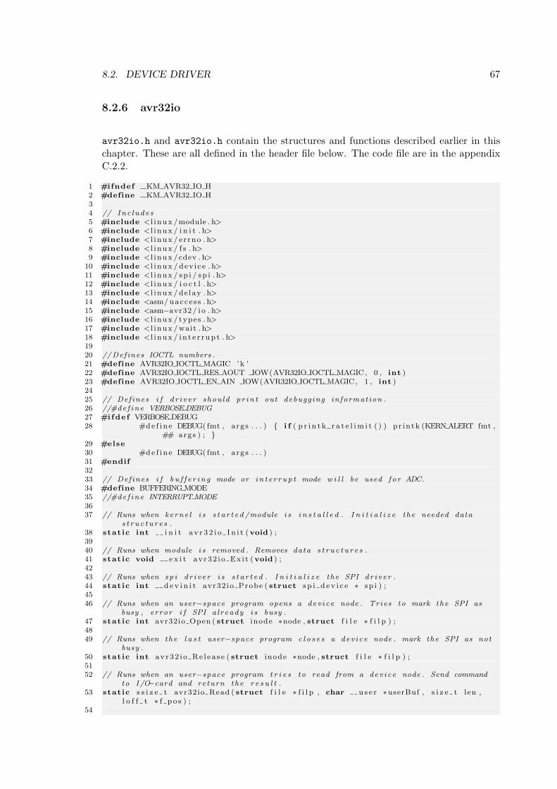
8.2. DEVICE DRIVER 67
8.2.6 avr32io
avr32io.h and avr32io.h contain the structures and functions described earlier in thischapter. These are all defined in the header file below. The code file are in the appendixC.2.2.
1 #ifndef KM AVR32 IO H2 #define KM AVR32 IO H34 // Inc ludes5 #include <l i nux /module . h>6 #include <l i nux / i n i t . h>7 #include <l i nux / errno . h>8 #include <l i nux / f s . h>9 #include <l i nux /cdev . h>
10 #include <l i nux / dev i ce . h>11 #include <l i nux / sp i / sp i . h>12 #include <l i nux / i o c t l . h>13 #include <l i nux / de lay . h>14 #include <asm/ uacce s s . h>15 #include <asm−avr32/ i o . h>16 #include <l i nux / types . h>17 #include <l i nux /wait . h>18 #include <l i nux / i n t e r r up t . h>1920 //Def ines IOCTL numbers .21 #define AVR32IO IOCTL MAGIC ’k ’22 #define AVR32IO IOCTL RES AOUT IOW(AVR32IO IOCTL MAGIC, 0 , int )23 #define AVR32IO IOCTL EN AIN IOW(AVR32IO IOCTL MAGIC, 1 , int )2425 // Def ines i f d r i v e r shou ld p r in t out debugging informat ion .26 //#de f ine VERBOSE DEBUG27 #ifdef VERBOSE DEBUG28 #de f i n e DEBUG( fmt , args . . . ) i f ( p r i n t k r a t e l im i t ( ) ) pr in tk (KERN ALERT fmt ,
## args ) ; 29 #else30 #de f i n e DEBUG( fmt , args . . . )31 #endif3233 // Def ines i f b u f f e r i n g mode or i n t e r r up t mode w i l l be used f o r ADC.34 #define BUFFERING MODE35 //#de f ine INTERRUPT MODE3637 // Runs when kerne l i s s t a r t e d /module i s i n s t a l l e d . I n i t i a l i z e the needed data
s t r u c t u r e s .38 stat ic int i n i t a v r 3 2 i o I n i t (void ) ;3940 // Runs when module i s removed . Removes data s t r u c t u r e s .41 stat ic void e x i t av r32 i o Ex i t (void ) ;4243 // Runs when sp i d r i v e r i s s t a r t e d . I n i t i a l i z e the SPI d r i v e r .44 stat ic int d e v i n i t avr32 io Probe ( struct s p i d e v i c e ∗ s p i ) ;4546 // Runs when an user−space program opens a dev i ce node . Tries to mark the SPI as
busy , error i f SPI a l ready i s busy .47 stat ic int avr32io Open ( struct inode ∗node , struct f i l e ∗ f i l p ) ;4849 // Runs when the l a s t user−space program c l o s e s a dev i ce node . mark the SPI as not
busy .50 stat ic int avr32 i o Re l ea s e ( struct inode ∗node , struct f i l e ∗ f i l p ) ;5152 // Runs when an user−space program t r i e s to read from a dev i ce node . Send command
to I /O−card and return the r e s u l t .53 stat ic s s i z e t avr32io Read ( struct f i l e ∗ f i l p , char u s e r ∗userBuf , s i z e t len ,
l o f f t ∗ f p o s ) ;54
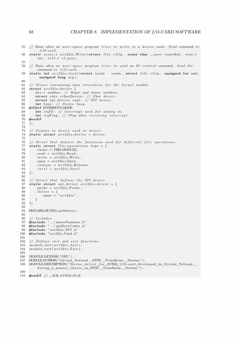
68 CHAPTER 8. IMPLEMENTATION OF I/O-CARD SOFTWARE
55 // Runs when an user−space program t r i e s to wr i t e to a dev i ce node . Send command toI /O−card .
56 stat ic s s i z e t avr32 io Wri te ( struct f i l e ∗ f i l p , const char u s e r ∗userBuf , s i z e tlen , l o f f t ∗ f p o s ) ;
5758 // Runs when an user−space program t r i e s to send an IO con t ro l command . Send the
command to I /O−card .59 stat ic int a v r 3 2 i o I o c t l ( struct inode ∗node , struct f i l e ∗ f i l p , unsigned int cmd ,
unsigned long arg ) ;6061 // S t ruc t conta in ing data s t r u c t u r e s f o r the ke rne l module .62 struct av r32 i o d ev i c e 63 dev t number ; // Major and minor numbers .64 struct cdev ∗ charDevice ; // Char dev i ce .65 struct s p i d e v i c e ∗ s p i ; // SPI dev i ce .66 int busy ; // Device busy .67 #ifdef INTERRUPT MODE68 int i rqID ; // In t e r rup t used f o r analog in .69 int i r qF lag ; // Flag when r e c e i v i n g i n t e r r up t .70 #endif71 ;7273 // Pointer to dev i ce used in d r i v e r .74 stat ic struct av r32 i o d ev i c e ∗ dev i ce ;7576 // S t ruc t t ha t d e f i n e s the func t i ons used fo r d i f f e r e n t f i l e opera t ions .77 stat ic struct f i l e o p e r a t i o n s fops = 78 . owner = THIS MODULE,79 . read = avr32io Read ,80 . wr i t e = avr32io Write ,81 . open = avr32io Open ,82 . r e l e a s e = avr32 io Re l ease ,83 . i o c t l = av r 3 2 i o I o c t l ,84 ;8586 // S t ruc t t ha t d e f i n e s the SPI d r i v e r .87 stat ic struct s p i d r i v e r a v r 3 2 i o d r i v e r = 88 . probe = avr32io Probe ,89 . d r i v e r = 90 . name = ”avr32 io ” ,91 92 ;9394 DECLARE MUTEX( spiMutex ) ;9596 // Inc ludes .97 #include ” . . / minorNumbers . h”98 #include ” . . / spiByteCodes . h”99 #include ”avr32 io SPI . h”
100 #include ”avr32io Cmd . h”101102 // Def ines i n i t and e x i t f unc t i ons .103 modu l e in i t ( a v r 3 2 i o I n i t ) ;104 module ex i t ( av r32 i o Ex i t ) ;105106 MODULE LICENSE( ”GPL”) ;107 MODULEAUTHOR( ”Oyvind Netland , NTNU, Trondheim , Norway”) ;108 MODULE DESCRIPTION( ”Device d r i v e r f o r AVR32 I /O−card developed by Oyvind Netland ,
dur ing a master t h e s i s on NTNU, Trondheim , Norway”) ;109110 #endif // KM AVR32 IO H
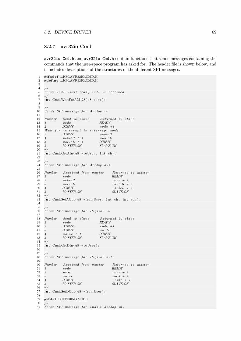
8.2. DEVICE DRIVER 69
8.2.7 avr32io Cmd
avr32io_Cmd.h and avr32io_Cmd.h contain functions that sends messages containing thecommands that the user-space program has asked for. The header file is shown below, andit includes descriptions of the structures of the different SPI messages.
1 #ifndef KM AVR32IO CMD H2 #define KM AVR32IO CMD H34 /∗5 Sends code u n t i l ready code i s r ece i v ed .6 ∗/7 int Cmd WaitForAM128( u8 code ) ;89 /∗
10 Sends SPI message f o r Analog in1112 Number Send to s l a v e Returned by s l a v e13 1 code READY14 2 DUMMY code +115 Wait f o r i n t e r r up t in i n t e r r up t mode .16 3 DUMMY vauleH17 4 valueH + 1 vauleL18 5 valueL + 1 DUMMY19 6 MASTER OK SLAVE OK20 ∗/21 int Cmd GetAIn( u8 ∗ toUser , int ch ) ;2223 /∗24 Sends SPI message f o r Analog out .2526 Number Received from master Returned to master27 1 code READY28 2 valueH code + 129 3 valueL vauleH + 130 4 DUMMY vauleL + 131 5 MASTER OK SLAVE OK32 ∗/33 int Cmd SetAOut( u8 ∗ fromUser , int ch , int sch ) ;3435 /∗36 Sends SPI message f o r D i g i t a l in3738 Number Send to s l a v e Returned by s l a v e39 1 code READY40 2 DUMMY code +141 3 DUMMY vau le42 4 va lue + 1 DUMMY43 5 MASTER OK SLAVE OK44 ∗/45 int Cmd GetDIn( u8 ∗ toUser ) ;4647 /∗48 Sends SPI message f o r D i g i t a l out .4950 Number Received from master Returned to master51 1 code READY52 2 mask code + 153 3 va lue mask + 154 4 DUMMY vau le + 155 5 MASTER OK SLAVE OK56 ∗/57 int Cmd SetDOut( u8 ∗ fromUser ) ;5859 #ifdef BUFFERING MODE60 /∗61 Sends SPI message f o r enab le analog in .
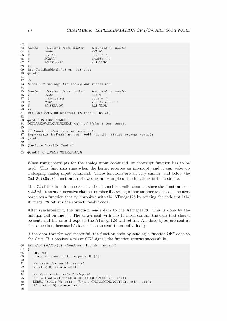
70 CHAPTER 8. IMPLEMENTATION OF I/O-CARD SOFTWARE
6263 Number Received from master Returned to master64 1 code READY65 2 enab le code + 166 3 DUMMY enab le + 167 5 MASTER OK SLAVE OK68 ∗/69 int Cmd EnableAIn ( u8 en , int ch ) ;70 #endif7172 /∗73 Sends SPI message f o r analog out r e s o l u t i on .7475 Number Received from master Returned to master76 1 code READY77 2 r e s o l u t i on code + 178 3 DUMMY re so l u t i on + 179 5 MASTER OK SLAVE OK80 ∗/81 int Cmd SetAOutResolution ( u8 r e s o l , int ch ) ;8283 #ifdef INTERRUPT MODE84 DECLARE WAIT QUEUE HEAD(wq) ; // Makes a wait queue .8586 // Function tha t runs on in t e r r up t .87 i r q r e t u r n t irqFunk ( int i rq , void ∗dev id , struct p t r e g s ∗ r eg s ) ;88 #endif8990 #include ”avr32io Cmd . c ”9192 #endif // KM AVR32IO CMD H
When using interrupts for the analog input command, an interrupt function has to beused. This functions runs when the kernel receives an interrupt, and it can wake upa sleeping analog input command. These functions are all very similar, and below theCmd_SetAOut() function are showed as an example of the functions in the code file.
Line 72 of this function checks that the channel is a valid channel, since the function from8.2.2 will return an negative channel number if a wrong minor number was used. The nextpart uses a function that synchronizes with the ATmega128 by sending the code until theATmega128 returns the correct “ready” code.
After synchronizing, the function sends data to the ATmega128. This is done by thefunction call on line 88. The arrays sent with this function contain the data that shouldbe sent, and the data it expects the ATmega128 will return. All three bytes are sent atthe same time, because it’s faster than to send them individually.
If the data transfer was successful, the function ends by sending a “master OK” code tothe slave. If it receives a “slave OK” signal, the function returns successfully.
66 int Cmd SetAOut( u8 ∗ fromUser , int ch , int sch )67 68 int r e t ;69 unsigned char tx [ 3 ] , expectedRx [ 3 ] ;7071 // check f o r v a l i d channel .72 i f ( ch < 0) return −EIO ;7374 // Synchronize with ATMega12875 r e t = Cmd WaitForAM128(CH TO CODE AOUT( ch , sch ) ) ;76 DEBUG( ”code : %i count : %i \n” , CH TO CODE AOUT( ch , sch ) , r e t ) ;77 i f ( r e t < 0) return r e t ;78
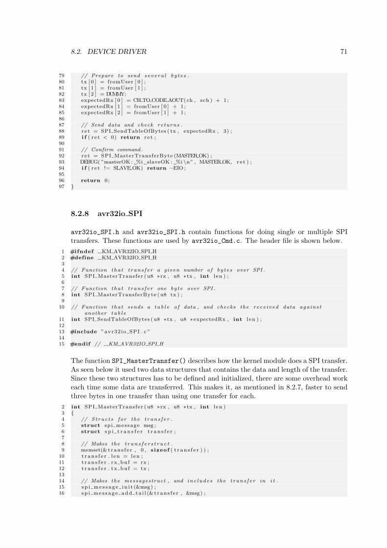
8.2. DEVICE DRIVER 71
79 // Prepare to send s e v e r a l b y t e s .80 tx [ 0 ] = fromUser [ 0 ] ;81 tx [ 1 ] = fromUser [ 1 ] ;82 tx [ 2 ] = DUMMY;83 expectedRx [ 0 ] = CH TO CODE AOUT( ch , sch ) + 1 ;84 expectedRx [ 1 ] = fromUser [ 0 ] + 1 ;85 expectedRx [ 2 ] = fromUser [ 1 ] + 1 ;8687 // Send data and check re turns .88 r e t = SPI SendTableOfBytes ( tx , expectedRx , 3) ;89 i f ( r e t < 0) return r e t ;9091 // Confirm command .92 r e t = SPI MasterTransferByte (MASTER OK) ;93 DEBUG( ”masterOK : %i slaveOK : %i \n” , MASTER OK, r e t ) ;94 i f ( r e t != SLAVE OK) return −EIO ;9596 return 0 ;97
8.2.8 avr32io SPI
avr32io_SPI.h and avr32io_SPI.h contain functions for doing single or multiple SPItransfers. These functions are used by avr32io_Cmd.c. The header file is shown below.
1 #ifndef KM AVR32IO SPI H2 #define KM AVR32IO SPI H34 // Function tha t t r an s f e r a g iven number o f by t e s over SPI .5 int SPI MasterTransfer ( u8 ∗ rx , u8 ∗ tx , int l en ) ;67 // Function tha t t r an s f e r one by te over SPI .8 int SPI MasterTransferByte ( u8 tx ) ;9
10 // Function tha t sends a t a b l e o f data , and checks the rece i v ed data aga in s tanother t a b l e
11 int SPI SendTableOfBytes ( u8 ∗ tx , u8 ∗expectedRx , int l en ) ;1213 #include ”avr32 io SPI . c ”1415 #endif // KM AVR32IO SPI H
The function SPI_MasterTransfer() describes how the kernel module does a SPI transfer.As seen below it used two data structures that contains the data and length of the transfer.Since these two structures has to be defined and initialized, there are some overhead workeach time some data are transferred. This makes it, as mentioned in 8.2.7, faster to sendthree bytes in one transfer than using one transfer for each.
2 int SPI MasterTransfer ( u8 ∗ rx , u8 ∗ tx , int l en )3 4 // S t ruc t s f o r the t r an s f e r .5 struct sp i message msg ;6 struct s p i t r a n s f e r t r a n s f e r ;78 // Makes the t r a n s f e r s t r u c t .9 memset(& t r an s f e r , 0 , s izeof ( t r a n s f e r ) ) ;
10 t r a n s f e r . l en = len ;11 t r a n s f e r . rx bu f = rx ;12 t r a n s f e r . tx bu f = tx ;1314 // Makes the messagestruct , and inc l ude s the t r an s f e r in i t .15 s p i me s s a g e i n i t (&msg) ;16 sp i me s s a g e add t a i l (& t r an s f e r , &msg) ;
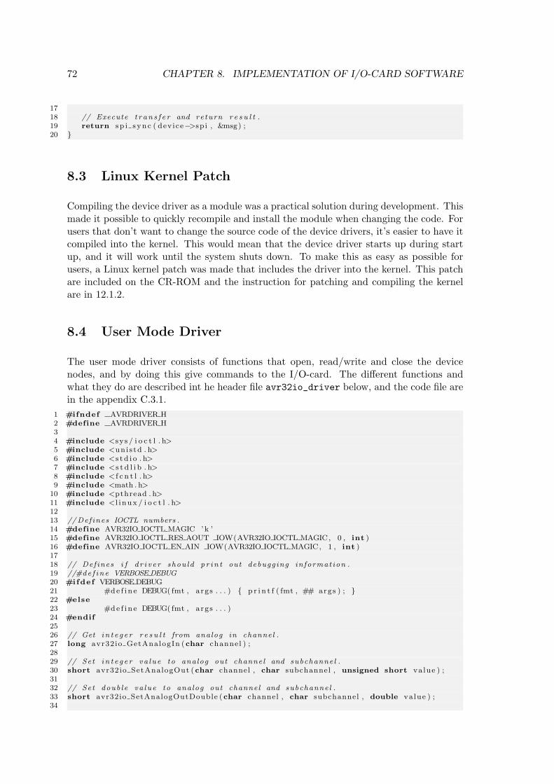
72 CHAPTER 8. IMPLEMENTATION OF I/O-CARD SOFTWARE
1718 // Execute t r an s f e r and return r e s u l t .19 return sp i s ync ( device−>sp i , &msg) ;20
8.3 Linux Kernel Patch
Compiling the device driver as a module was a practical solution during development. Thismade it possible to quickly recompile and install the module when changing the code. Forusers that don’t want to change the source code of the device drivers, it’s easier to have itcompiled into the kernel. This would mean that the device driver starts up during startup, and it will work until the system shuts down. To make this as easy as possible forusers, a Linux kernel patch was made that includes the driver into the kernel. This patchare included on the CR-ROM and the instruction for patching and compiling the kernelare in 12.1.2.
8.4 User Mode Driver
The user mode driver consists of functions that open, read/write and close the devicenodes, and by doing this give commands to the I/O-card. The different functions andwhat they do are described int he header file avr32io_driver below, and the code file arein the appendix C.3.1.
1 #ifndef AVRDRIVER H2 #define AVRDRIVER H34 #include <sys / i o c t l . h>5 #include <un i s td . h>6 #include <s t d i o . h>7 #include <s t d l i b . h>8 #include < f c n t l . h>9 #include <math . h>
10 #include <pthread . h>11 #include <l i nux / i o c t l . h>1213 //Def ines IOCTL numbers .14 #define AVR32IO IOCTL MAGIC ’k ’15 #define AVR32IO IOCTL RES AOUT IOW(AVR32IO IOCTL MAGIC, 0 , int )16 #define AVR32IO IOCTL EN AIN IOW(AVR32IO IOCTL MAGIC, 1 , int )1718 // Def ines i f d r i v e r shou ld p r in t out debugging informat ion .19 //#de f ine VERBOSE DEBUG20 #ifdef VERBOSE DEBUG21 #de f i n e DEBUG( fmt , args . . . ) p r i n t f ( fmt , ## args ) ; 22 #else23 #de f i n e DEBUG( fmt , args . . . )24 #endif2526 // Get i n t e g e r r e s u l t from analog in channel .27 long avr32io GetAnalogIn (char channel ) ;2829 // Set i n t e g e r va lue to analog out channel and subchannel .30 short avr32io SetAnalogOut (char channel , char subchannel , unsigned short value ) ;3132 // Set doub le va lue to analog out channel and subchannel .33 short avr32io SetAnalogOutDouble (char channel , char subchannel , double value ) ;34
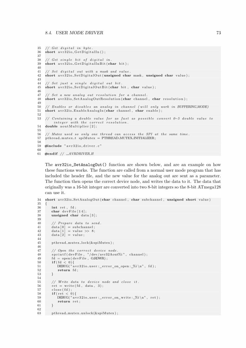
8.4. USER MODE DRIVER 73
35 // Get d i g i t a l in by te .36 short av r32 i o Ge tD ig i t a l I n ( ) ;3738 // Get s i n g l e b i t o f d i g i t a l in .39 short av r32 i o Ge tD ig i t a l I nB i t (char b i t ) ;4041 // Set d i g i t a l out with a mask and va lue .42 short avr32 i o Se tD ig i t a lOut (unsigned char mask , unsigned char value ) ;4344 // Set j u s t a s i n g l e d i g i t a l out b i t .45 short avr32 i o Se tD ig i t a lOutB i t (char bit , char value ) ;4647 // Set a new analog out r e s o l u t i on fo r a channel .48 short avr32 io SetAnalogOutReso lut ion (char channel , char r e s o l u t i o n ) ;4950 // Enables or d i s a b l e s an analog in channel ( w i l l on ly work in BUFFERING MODE)51 short avr32io EnableAnalogIn (char channel , char enable ) ;5253 // Containing a doub le va lue f o r as f a s t as p o s s i b l e conver t 0−5 doub le va lue to
i n t e g e r with the cor r ec t r e s o l u t i on .54 double aou tMu l t i p l i e r [ 2 ] ;5556 // Mutex used so only one thread can access the SPI at the same time .57 pthread mutex t spiMutex = PTHREAD MUTEX INITIALIZER;5859 #include ”av r 3 2 i o d r i v e r . c ”6061 #endif // AVRDRIVER H
The avr32io_SetAnalogOut() function are shown below, and are an example on howthese functions works. The function are called from a normal user mode program that hasincluded the header file, and the new value for the analog out are sent as a parameter.The function then opens the correct device node, and writes the data to it. The data thatoriginally was a 16-bit integer are converted into two 8-bit integers so the 8-bit ATmega128can use it.
34 short avr32io SetAnalogOut (char channel , char subchannel , unsigned short value )35 36 int ret , fd ;37 char devFi l e [ 1 4 ] ;38 unsigned char data [ 3 ] ;3940 // Prepare data to send .41 data [ 0 ] = subchannel ;42 data [ 1 ] = value >> 8 ;43 data [ 2 ] = value ;4445 pthread mutex lock(&spiMutex ) ;4647 // Open the cor r ec t dev i ce node .48 s p r i n t f ( devFi le , ”/dev/avr32Aout%i ” , channel ) ;49 fd = open ( devFi le , ORDWR) ;50 i f ( fd < 0) 51 DEBUG( ”av r32 i o u s e r : e r r o r on open : %i \n” , fd ) ;52 return fd ;53 5455 // Write data to dev i ce node and c l o s e i t .56 r e t = wr i t e ( fd , data , 3) ;57 c l o s e ( fd ) ;58 i f ( r e t < 0) 59 DEBUG( ”av r32 i o u s e r : e r r o r on wr i t e : %i \n” , r e t ) ;60 return r e t ;61 6263 pthread mutex unlock(&spiMutex ) ;
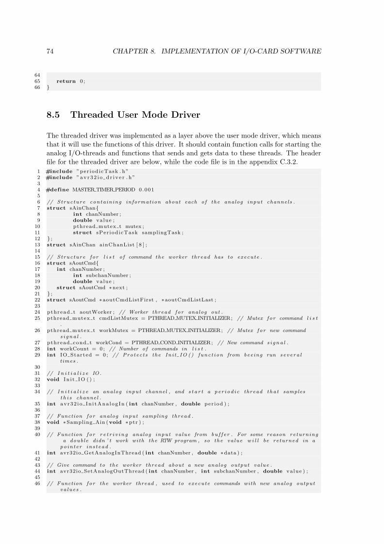
74 CHAPTER 8. IMPLEMENTATION OF I/O-CARD SOFTWARE
6465 return 0 ;66
8.5 Threaded User Mode Driver
The threaded driver was implemented as a layer above the user mode driver, which meansthat it will use the functions of this driver. It should contain function calls for starting theanalog I/O-threads and functions that sends and gets data to these threads. The headerfile for the threaded driver are below, while the code file is in the appendix C.3.2.
1 #include ”per iod icTask . h”2 #include ”av r 3 2 i o d r i v e r . h”34 #define MASTER TIMER PERIOD 0.00156 // Struc ture conta in ing informat ion about each o f the analog input channels .7 struct sAinChan8 int chanNumber ;9 double value ;
10 pthread mutex t mutex ;11 struct sPer iod icTask samplingTask ;12 ;13 struct sAinChan ainChanList [ 8 ] ;1415 // Struc ture f o r l i s t o f command the worker thread has to execute .16 struct sAoutCmd17 int chanNumber ;18 int subchanNumber ;19 double value ;20 struct sAoutCmd ∗next ;21 ;22 struct sAoutCmd ∗aoutCmdListFirst , ∗aoutCmdListLast ;2324 pthread t aoutWorker ; // Worker thread fo r analog out .25 pthread mutex t cmdListMutex = PTHREAD MUTEX INITIALIZER; // Mutex f o r command l i s t
.26 pthread mutex t workMutex = PTHREAD MUTEX INITIALIZER; // Mutex f o r new command
s i g n a l .27 pthread cond t workCond = PTHREAD COND INITIALIZER; // New command s i g n a l .28 int workCount = 0 ; // Number o f commands in l i s t .29 int IO Started = 0 ; // Pro tec t s the In i t IO () func t i on from bee ing run s e v e r a l
t imes .3031 // I n i t i a l i z e IO .32 void I n i t IO ( ) ;3334 // I n i t i a l i z e an analog input channel , and s t a r t a pe r i od i c thread tha t samples
t h i s channel .35 int avr32 i o In i tAna log In ( int chanNumber , double per iod ) ;3637 // Function fo r analog input sampling thread .38 void ∗Sampling Ain (void ∗ptr ) ;3940 // Function fo r r e t r i v i n g analog input va lue from bu f f e r . For some reason re turn ing
a doub le didn ’ t work with the RTW program , so the va lue w i l l be returned in apo in t e r in s t ead .
41 int avr32io GetAnalogInThread ( int chanNumber , double ∗data ) ;4243 // Give command to the worker thread about a new analog output va lue .44 int avr32io SetAnalogOutThread ( int chanNumber , int subchanNumber , double value ) ;4546 // Function fo r the worker thread , used to execute commands with new analog output
va lue s .
8.5. THREADED USER MODE DRIVER 75
47 void ∗Worker Aout ( ) ;4849 #include ”av r32 i o th r ead s . c ”
8.5.1 Threaded Analog Input
To make periodic tasks that samples from the I/O-card, this driver uses the periodicTasklibrary, that allows to easily make periodic threads. These tasks samples from the I/O-card and store the analog values in variables, that are protected by a mutex. A functionavr32io_GetAnalogInThread is used by the main thread to get the currently bufferedvalue.
The SPI connection is also protected by a mutex, to avoid that two threads tries to use itat the same time. The device driver also has protection against this, that will return anerror if the SPI connection is busy. By using a mutex here, these errors are avoided, andit’s therefore a better solution.
8.5.2 Threaded Analog Output
The worker thread starts a forever loop and waits for a signal from the main thread. Thissignal is a pthread condition variable, and is the same type of signals that are used tocontrol the periodic tasks in periodicTaks. When the worker thread receives a signal itmeans that there is one or more items in the command list. This list is a single linkedlist that contain information about new values to analog out channels. After receiving thesignal, the thread starts executing the commands in the list, one at the time until the listit empty. This list has to be protected with mutexes as well, so new items won’t get addedto the list while the worker thread reads a command from it.

76 CHAPTER 8. IMPLEMENTATION OF I/O-CARD SOFTWARE
Chapter 9
Testing with prototype card
This chapter desribes tests performed on the prototype card and the software developedfor it. The parts that are tested, are the API communication and the analog I/O.
9.1 Test of SPI communication
9.1.1 Frequency of SPI connection
In 5.5.4 the highest possible SPI frequency was about 1.9MHz, which was about one quar-ter of the clock frequency of STK500. When using a clock twice as high, the ATmega128should be able to receive SPI transfers with twice as high frequency. In avr32io.c thefollowing line sets the SPI frequency to the highest that works with ATmega128 as slave.sp i−>max speed hz = 2100000;
When using an oscilloscope to probe the SPI clock, the time used by one high and onelow period was measured to 0.25µs. This is the time used to transfer one bit of data.This gives a frequency of 4MHz. This is one quarter of the frequency of the ATmega128,which is the theoretical maximum.
9.1.2 Time used on SPI transfers
In 9.1.1 the time used to transfer one bit of data was measured to 0.25µs. The SPI transferconsists of 8 bits of data serially, which means that the total 8 bits (= 1 byte) takes 2µs.To test how much time the kernel uses before and between SPI transfers, a small testsystem was created that sent out pairs of data transfers. By using an oscilloscope, thetime between the two pairs of data was measured. The test system could send pairs ofdata in two different ways. Either sending two individual bytes of data, or sending twobytes of data at the time.
When sending two individual bytes, the test system used 23.5µs from the end of the firstto the start of the last byte. When sending the two bytes at the same time, this time wasreduced to 9.2µs. First of all, this means that the AVR32 uses much more time preparingand configuring the SPI transfer than it uses on the SPI transfer itself. It also means that
77
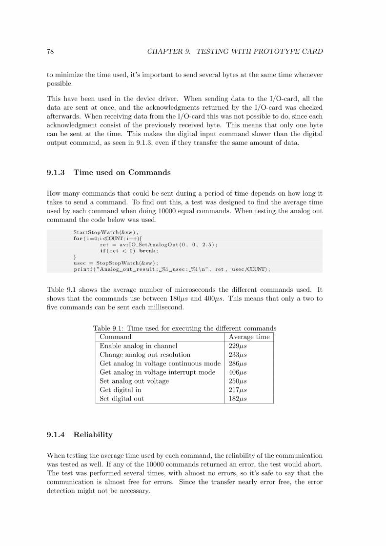
78 CHAPTER 9. TESTING WITH PROTOTYPE CARD
to minimize the time used, it’s important to send several bytes at the same time wheneverpossible.
This have been used in the device driver. When sending data to the I/O-card, all thedata are sent at once, and the acknowledgments returned by the I/O-card was checkedafterwards. When receiving data from the I/O-card this was not possible to do, since eachacknowledgment consist of the previously received byte. This means that only one bytecan be sent at the time. This makes the digital input command slower than the digitaloutput command, as seen in 9.1.3, even if they transfer the same amount of data.
9.1.3 Time used on Commands
How many commands that could be sent during a period of time depends on how long ittakes to send a command. To find out this, a test was designed to find the average timeused by each command when doing 10000 equal commands. When testing the analog outcommand the code below was used.
StartStopWatch(&sw) ;for ( i =0; i<COUNT; i++)
r e t = avrIO SetAnalogOut (0 , 0 , 2 . 5 ) ;i f ( r e t < 0) break ;
usec = StopStopWatch(&sw) ;p r i n t f ( ”Analog out r e s u l t : %i usec : %i \n” , ret , usec /COUNT) ;
Table 9.1 shows the average number of microseconds the different commands used. Itshows that the commands use between 180µs and 400µs. This means that only a two tofive commands can be sent each millisecond.
Table 9.1: Time used for executing the different commandsCommand Average timeEnable analog in channel 229µsChange analog out resolution 233µsGet analog in voltage continuous mode 286µsGet analog in voltage interrupt mode 406µsSet analog out voltage 250µsGet digital in 217µsSet digital out 182µs
9.1.4 Reliability
When testing the average time used by each command, the reliability of the communicationwas tested as well. If any of the 10000 commands returned an error, the test would abort.The test was performed several times, with almost no errors, so it’s safe to say that thecommunication is almost free for errors. Since the transfer nearly error free, the errordetection might not be necessary.
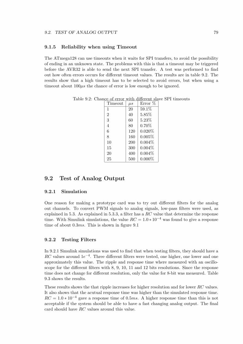
9.2. TEST OF ANALOG OUTPUT 79
9.1.5 Reliability when using Timeout
The ATmega128 can use timeouts when it waits for SPI transfers, to avoid the possibilityof ending in an unknown state. The problems with this is that a timeout may be triggeredbefore the AVR32 is able to send the next SPI transfer. A test was performed to findout how often errors occurs for different timeout values. The results are in table 9.2. Theresults show that a high timeout has to be selected to avoid errors, but when using atimeout about 100µs the chance of error is low enough to be ignored.
Table 9.2: Chance of error with different slave SPI timeoutsTimeout µs Error %1 20 59.1%2 40 5.85%3 60 5.23%4 80 0.70%6 120 0.020%8 160 0.005%10 200 0.004%15 300 0.004%20 400 0.004%25 500 0.000%
9.2 Test of Analog Output
9.2.1 Simulation
One reason for making a prototype card was to try out different filters for the analogout channels. To convert PWM signals to analog signals, low-pass filters were used, asexplained in 5.3. As explained in 5.3.3, a filter has a RC value that determine the responsetime. With Simulink simulations, the value RC = 1.0 ∗ 10−4 was found to give a responsetime of about 0.3ms. This is shown in figure 9.1
9.2.2 Testing Filters
In 9.2.1 Simulink simulations was used to find that when testing filters, they should have aRC values around 1e−4. Three different filters were tested, one higher, one lower and oneapproximately this value. The ripple and response time where measured with an oscillo-scope for the different filters with 8, 9, 10, 11 and 12 bits resolutions. Since the responsetime does not change for different resolution, only the value for 8-bit was measured. Table9.3 shows the results.
These results shows the that ripple increases for higher resolution and for lower RC values.It also shows that the acutual response time was higher than the simulated response time.RC = 1.0 ∗ 10−4 gave a response time of 0.5ms. A higher response time than this is notacceptable if the system should be able to have a fast changing analog output. The finalcard should have RC values around this value.

80 CHAPTER 9. TESTING WITH PROTOTYPE CARD
0 0.2 0.4 0.6 0.8 1
x 10−3
0
0.5
1
1.5
2
2.5
3
3.5
4
4.5
5
Time
Vol
t
Figure 9.1: RC = 1.0 ∗ 10−4 gives a response time of 0.3ms.
Table 9.3: Results of analog output filtersR C RC Response time Resolution Ripple0.36kΩ 100nF 0.36 ∗ 10−4 0.2ms 8-bit 20mV
9-bit 75mV10-bit 222mV11-bit 640mV12-bit 1400mV
1kΩ 100nF 1.0 ∗ 10−4 0.5ms 8-bit 5mV9-bit 15mV10-bit 45mV11-bit 140mV12-bit 400mV
3kΩ 100nF 3.0 ∗ 10−4 1.3ms 8-bit < 5mV9-bit 5mV10-bit 10mV11-bit 25mV12-bit 70mV
9.2.3 Operational Amplifiers
When connecting the op amps to the prototype card, the op amps was only able to giveout voltages between 2V and 3V . This is because the op amp that was used (MC1458)could not give outputs that was less than (V − + 2V ) or more than (V + − 2V ). SinceV − = GND and V + = VCC the output range became limited. The final version of thecard should have another type of op-amps and these will need other supply voltages.
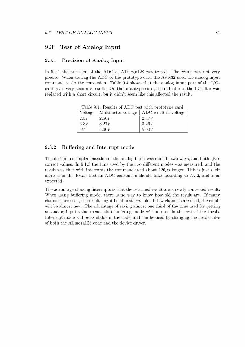
9.3. TEST OF ANALOG INPUT 81
9.3 Test of Analog Input
9.3.1 Precision of Analog Input
In 5.2.1 the precision of the ADC of ATmega128 was tested. The result was not veryprecise. When testing the ADC of the prototype card the AVR32 used the analog inputcommand to do the conversion. Table 9.4 shows that the analog input part of the I/O-card gives very accurate results. On the prototype card, the inductor of the LC-filter wasreplaced with a short circuit, bu it didn’t seem like this affected the result.
Table 9.4: Results of ADC test with prototype cardVoltage Multimeter voltage ADC result in voltage2.5V 2.50V 2.47V3.3V 3.27V 3.26V5V 5.00V 5.00V
9.3.2 Buffering and Interrupt mode
The design and implementation of the analog input was done in two ways, and both givescorrect values. In 9.1.3 the time used by the two different modes was measured, and theresult was that with interrupts the command used about 120µs longer. This is just a bitmore than the 104µs that an ADC conversion should take according to 7.2.2, and is asexpected.
The advantage of using interrupts is that the returned result are a newly converted result.When using buffering mode, there is no way to know how old the result are. If manychannels are used, the result might be almost 1ms old. If few channels are used, the resultwill be almost new. The advantage of saving almost one third of the time used for gettingan analog input value means that buffering mode will be used in the rest of the thesis.Interrupt mode will be available in the code, and can be used by changing the header filesof both the ATmega128 code and the device driver.

82 CHAPTER 9. TESTING WITH PROTOTYPE CARD
Chapter 10
Final version of I/O-card
The purpose of the prototype card was to make a customizable card with good debuggingcapabilities, while the new and final version of the card was designed to be of less physicalsize and easier to use. The new card also had corrected the flaws of the prototype cardand introduced a few extra features.
10.1 Changes from Prototype
Used SMD components when possible, which makes the card smaller.
Removed the RS-232 connection, since this was only used for debugging. This makesthe card smaller, and also reduced total cost of the card, since the MAX233 is fairlyexpensive. The UART signals of the ATmega128 were made available on headers,so it’s possible to use them if needed.
Added header interface for the NGW board. This is a new AVR32 developmentboard that has a slightly different expansion header than STK1000. The headers arealso smaller, and only use the necessary signals. The interrupt signal was no longersent through the normal header, but has to use another wire between a interruptheader on the I/O card and the header on the STK1000/NGW.
Used headers for digital I/O instead of screw clamps. The choice of screw clampsfor these signals was a mistake, since they took to much space. Headers are smallerand equally easy to use. They are also commonly used for digital signals.
Added a bridge rectifier before the voltage regulator. This means that the polarity ofthe external power source doesn’t matter. Without a rectifier, the voltage regulatormight be broken if a negative voltage is applied. This makes the card more “fool-proof”.
Added a screw clamp power supply in addition to the ordinary power jack plug. Thismakes it easy to connect different power sources.
On the new card all screw clamps and headers are marked with numbers that corre-sponds to the number of pin on ATmega128. Analog in channel 0 is the same as the
83
84 CHAPTER 10. FINAL VERSION OF I/O-CARD
ADC0 pin on ATmega128, and so on. Ordering these signals gives a slightly morecomplex routing, but it’s more practical and easy to use.
A new type of op amps were used, to correct the flaw described in 9.2.3. Theseop-amps are single supply op amps, that are able to give output between GND and(V + − 2V ). As V + the rectified but unregulated power supply was used, since theop amp don’t need regulated power supply. This means that the output range of theop amp are defined by the supply voltage of the I/O-card. The disadvantage of thissolution is that the op-amps, and therefor the analog output, will not work whenrunning on power from the STK1000 board.
All three subchannels on the first channel (channel 0) of the analog out was designedwith two jumpers each. One of these jumpers were used to bypass the filter, meaningthat the output will be a PWM signal instead of a analog signal. This is useful whenusing components like servos. The other jumper are used to change the op-ampcircuit from being a voltage follower to a non-inverting amplifier that amplifies the0V − 5V signal to a 0V − 10V signal. To use this option, the power supply has tobe high enough so the op-amps can give out 10V .
The PWM filters were made with resistors with value R = 3.9kΩ and capacitorswith value C = 22nF , giving them RC = 8.58 ∗ 10−5. This should give a responsetime around half a millisecond.
10.2 Schematic
The whole schematic of the final version of the card are in the appendix B.2. This schematicis the same as the prototype except for the changes described in 10.1
10.3 Layout
The layout of the final I/O-card are shown in 10.1 on the facing page and 10.2 on the nextpage. Since it used SMD components whenever possible and other design changes, thiscard was almost half the size of the prototype. Since more components are SMD, almostall of them were placed on the top layer of the card instead of the bottom layer on theprototype. Since the I/O-signals were ordered after pin numbers, it meant that the routingof signals was more complex than for the prototype card. This made the gain of placingthe ATmega128 on the bottom layer less than for the prototype card, since both solutionswould be equally complex. Therefor the top layer was chosen because of cosmetic reasons.
Figure 10.3 on page 86 is an image of an almost assembeled final version of the I/O-card.
10.4 Problems with Analog Output
The new I/O-card also had problems with the analog output. The operational amplifiersand the supply voltage for these worked better than on the prototype, but the filters forconverting the PWM signals to analog voltages didn’t work. They gave out lower voltages
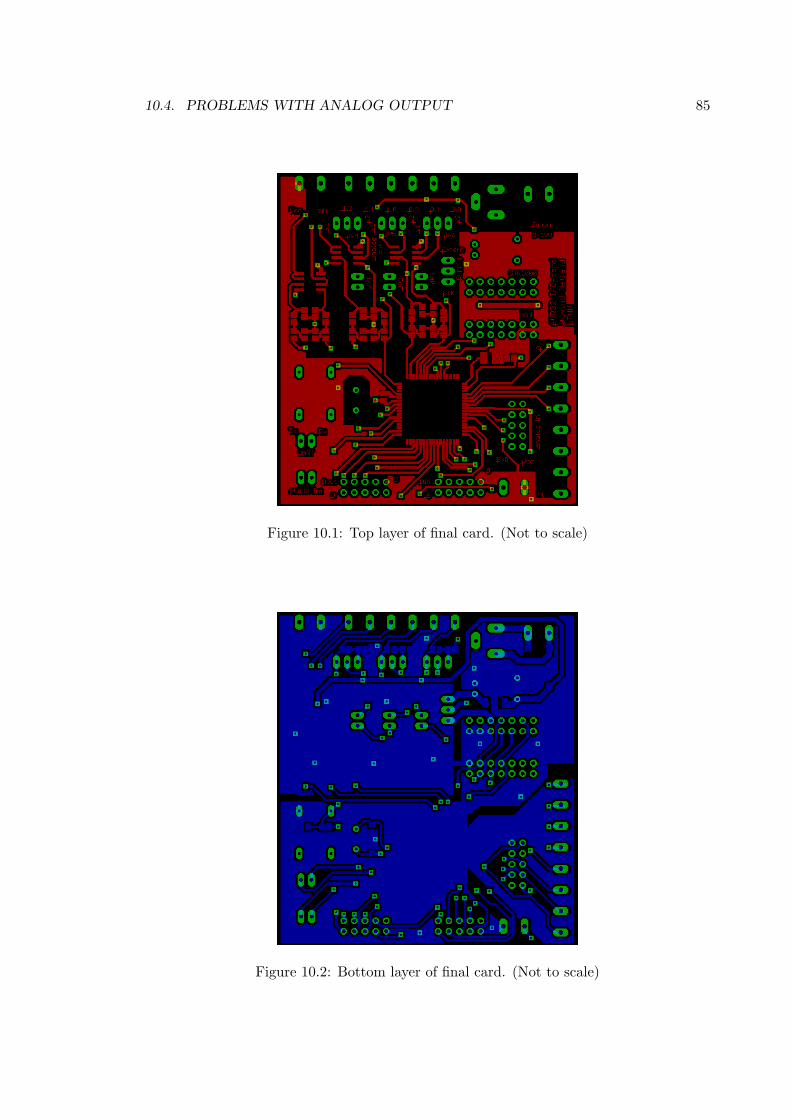
10.4. PROBLEMS WITH ANALOG OUTPUT 85
Figure 10.1: Top layer of final card. (Not to scale)
Figure 10.2: Bottom layer of final card. (Not to scale)
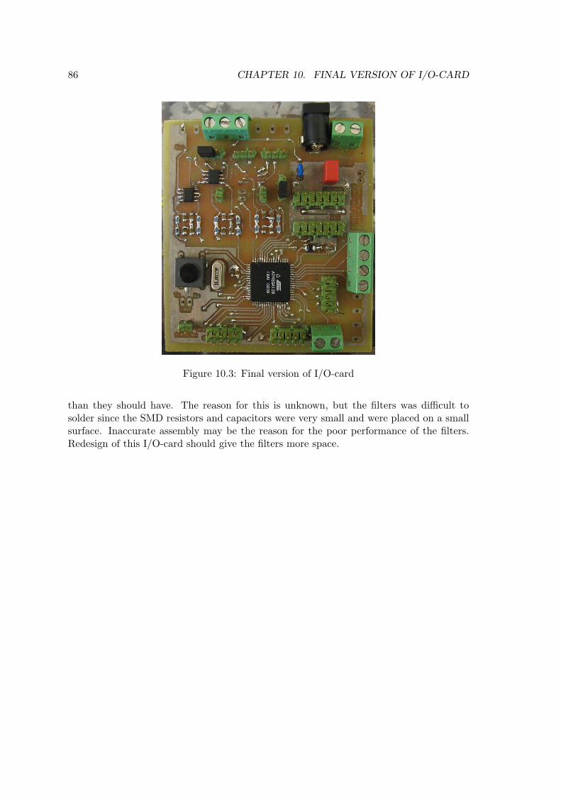
86 CHAPTER 10. FINAL VERSION OF I/O-CARD
Figure 10.3: Final version of I/O-card
than they should have. The reason for this is unknown, but the filters was difficult tosolder since the SMD resistors and capacitors were very small and were placed on a smallsurface. Inaccurate assembly may be the reason for the poor performance of the filters.Redesign of this I/O-card should give the filters more space.
Chapter 11
Matlab Real-Time Workshop
11.1 Matlab Real-Time Workshop
Matlab Simulink can be used to design and simulate mathematical models. With thehelp of Matlab Real-Time Workshop (RTW for short) C-code can be generated from theSimulink model. The code will (if compiled) give a program that does the same simulationas in Simulink. This can be used for rapid prototyping control systems, as described in2.4. How to use RTW is described in [13]
11.1.1 Target Language Compiler (TLC)
When Matlab Real-Time workshop generates C-code from a Simulink diagram it actuallydoes it in two steps. The first step is to make a .rtw file. This file contains all theinformation from the Simulink diagram presented in a hierarchy The TLC language isdescribes in detail in [12].
The TLC is the second step of the code generation, and it generates multiple sourcefiles from the information in the .rtw file and several .tlc files. The .rtw file containsinformation about the Simulink diagram, while the different .tlc files contain informationon how the generated code should look like.
It’s two different types of .tlc files. The system target file specify the overall structure ofthe generated code, and it’s selected before generating code among a list of system targetfiles supplied with RTW. It’s also possible to change existing or make new system targetfiles. For rapid prototyping the general real-time target (grt) is a good starting point.This makes C-code that can run on most platforms, as shown in 4.3.
Code generated with grt, will as in Simulink execute the simulation as fast as possible. Acontrol system has to execute the simulation with correct time between each time step, orit wouldn’t work as intended. To make this possible with grt, some of the code have to bemodified.
Each Simulink block has its own block target file. This file contain the information TLCneeds to generate code that does the same as the block would do in Simulink.
87

88 CHAPTER 11. MATLAB REAL-TIME WORKSHOP
11.1.2 S-functions
S-functions are Simulink blocks written in a computer programming language, like Matlabsown language M, C, C++, Ada and FORTRAN. This allows users to add their own blocksin Simulink, that can have functionality that normal Simulink blocks can’t provide. Whenusing Matlab RTW as a rapid prototyping tool for a control system, S-functions are oftenused to control I/O.
S-functions are written as a code file for the selected computer language, but this file hasto follow a specific structure. To use the S-function the code has to be compiled using theMatlab command mex. As for other compiled program, this file has to be compiled againeach time changes have been made.
When using RTW, it’s possible to use three types of S-functions, that are described below.
Noninlined S-functions are S-functions that doesn’t have a .tlc file, which meansthat it’s treated equally by Simulink and RTW. This is the easiest solution, sinceeverything that works in Simulink will work equally in RTW, and it’s not necessary towrite any TLC code. Unfortunately this is not very efficient, and will need additionalCPU and memory usage when running a program from the generated code.
Fully inlined S-functions have a .tlc (target block) file, and the behavior of theS-function in RTW is defined by this file, and not by the S-function code file usedby Simulink. This means that the S-function might not do the same thing whensimulating in Simulink as, when running the program made by RTW generatedcode. This can both be a good and a bad feature. If the block is supposed to do thesame in both cases, it will be error-prone and time consuming to upgrade two files atthe same time. In some applications like controlling I/O, it might be preferable thatthe Simulink simulation does something different than the RTW generated code.
Wrapper S-functions are a special type of inlined S-functions, where a third codefile is used. This file has functions that both the .tlc file and S-function code filesuses. This allows the Simulink and RTW to execute the same code as in a noninlinedS-function, but without the loss of performance.
11.2 Making a AVR32 Real-Time Target
When using Matlab RTW, a system target has to be chosen. This system target defineshow code will be generated and compiled. As mentioned in 11.1.1, the GRT system targetgenerates code that will run on most platforms, and in 4.3 GRT generated code with afew modifications, compiled and ran on AVR32.
One of the goals with this thesis is to make a system that is easy to install and use.Because of this, a new system target was created, based on the GRT. This system targetwas named AVR32 Real-Time Target and will be installed by moving a directory intoMATLAB_ROOT/rtw/c.
11.2. MAKING A AVR32 REAL-TIME TARGET 89
11.2.1 avr32.tlc
This is the system target file for the new AVR32 Real-Time Target, and it’s the file thatcontrols how code are generated. Since the code generated by GRT will compile andrun on AVR32 with a few modifications to the Makefile, this file will be very similar togrt.tlc. The few changes necessary are to specify a new Makefile template and changesome names.
Each system target has a short text that describes itself, which is showed in the listwhere users can choose system targets. To change this text, and specify a new Makefile,the following lines has to be added to the top of the avr32.tlc file. Any similar lines(containing SYSTLC or TMF) should be removed.
1 %% SYSTLC: AVR32 Real−Time Target \2 %% TMF: avr32 . tmf MAKE: make rtw EXTMODE: ext comm
In the end of the grt.tlc file, a suffix for the generated code directory is specified. Thisshould be changed to another name by using the line below instead of the original line.
168 r twgens e t t i ng s . Bu i l dD i rSu f f i x = ’ avr32 rtw ’ ;
11.2.2 avr32.tmf
This is the Makefile template of the system target, that was made by doing some modifica-tions to the grt_unix.tmf file. The Makefile template for GRT on UNIX/Linux platforms.The first change was to replace the “grt.tlc” with “avr32.tlc” as system target file. This isdone changing the original system target file definition with the line below.
46 SYS TARGET FILE = avr32 . t l c
The next step is to change the compiler and compiler flags used by the Makefile. This isdone by adding the following lines before the “C flags” section of the original template.This should be around line 185 of the original file.
182 #−−−−−−−−−−−−−−−−−−−−−−−−−−−−−−− AVR32 Sp e c i f i c −−−−−−−−−−−−−−−−−−−−−−−−−−−−−−−−183184 #AVR32 compi lator185 CC=avr32−l inux−gcc186187 #Removes −m32188 OPT OPTS = −O − f f l o a t −s t o r e −fPIC189190 #Links with pthread191 LDFLAGS = −l p thread192193 #enab l e s // comments194 ANSI OPTS =
The line starting with CC are used to specify the AVR32 compiler, and the line withOPT_OPTS are used to remove the -m32 flag causes an error, as I discovered in 4.3. Thisflag specifies that the target is a 32-bit processor, and is unknown for the AVR32 compiler.With these two changes, the compilation to AVR32 works, and it produces a runnableexecutable.
The line starting with LDFLAGS means that the executable will be linked with the pthreadlibrary. This is required for using pthread, that are needed for using threads, mutexes and
90 CHAPTER 11. MATLAB REAL-TIME WORKSHOP
other pthread functionality. The last line was used to remove the -ansi flag. This doesn’taffect the compilation, it will only make it possible to comment code with double slash //.
The next issue that needs to be modified is the C file containing the main function usedby the generated code. This is done by replacing the grt_main.c with avr32_main.c inline 233 of the original file. The new line should then look like this:
244 SRCS += $ (MODEL) . $ (TARGET LANG EXT) avr32 main . c r t s im . c $ (EXT SRC) $ (SOLVER)
Since the new AVR32 target files are in another directory than the GRT target files, theMakefile has to be changed so it compiles the correct files. This are done by adding thefollowing lines. The lines that are equal but contain the rtw/c/grt instead should beremoved.
339 %.o : $ (MATLAB ROOT)/rtw/c/avr32/%.c340 @$(GCC TEST CMD) $< $ (GCC TEST OUT)341 $ (CC) −c $ (CFLAGS) $ (GCC WALL FLAG MAX) $<
11.2.3 avr32main.c
The Makefile template specifies that the new system target will use a C file namedavr32_main.c. This file is also based on the GRT C file called grt_main.c. As men-tioned in 11.1.1, GRT version of the file makes a program that execute all time-steps asfast as possible. The reason for modifying the avr32_main.c is to make a control systemthat executes the time steps of the simulation periodically, and it has to include the filesnecessary to use the I/O-card.
For making the program execute the time steps periodically periodicTask library pre-sented and used in 4.2 was used. The I/O-card user mode driver has to be included,since they are used by the S-functions, see 11.3. For debugging and testing of the RTWgenerated code, the stopWatch library was used. This was used to calculate how muchtime the AVR32 used on each of the time step.
The following lines was added after the other #include statements of the original file.These lines contain the different files required by this new main function file. The threadedversion of the user mode driver was included, since it includes the non-threaded version.
48 /∗ AVR32 inc l ude s ∗/49 #include ”d r i v e r / av r32 i o th r ead s . h”50 #include ”d r i v e r / per iod icTask . h”51 #include ”d r i v e r / stopwatch . h”
The following lines are global structures and variables that are needed to make the timesteps periodical and to measure the workload,
156 /∗===================∗157 ∗ Globa l AVR32 Data ∗158 ∗===================∗/159 struct sPer iod icTask matlabSimulat ionPer iode ;160 struct sStopWatch timerStopWatch , workStopWatch ;161 long usecWork , usecTimer ;162 int count=0;
The following lines are added to make the time steps periodical. These should be addedtwice in the file, one time for single tasking and one for multitasking. Both places where
11.3. S-FUNCTIONS FOR I/O-CARD 91
this function should be added are marked in the original file with a comment saying that“interrupts should be enabled here”.
227 /∗ ∗∗∗∗∗∗∗∗∗∗∗∗∗∗∗∗∗∗∗∗∗∗∗∗∗228 ∗ AVR32 Timing i n t e r r up t ∗229 ∗∗∗∗∗∗∗∗∗∗∗∗∗∗∗∗∗∗∗∗∗∗∗∗∗ ∗/230 StartStopWatch(&timerStopWatch ) ;231 usecWork += StopStopWatch(&workStopWatch ) ;232 WaitPeriodicTask(&matlabSimulat ionPer iode ) ;233 usecTimer += StopStopWatch(&timerStopWatch ) ;234 StartStopWatch(&timerStopWatch ) ;235 StartStopWatch(&workStopWatch ) ;236 count++;
The WaitPeriodicTask function is a function that wait until the next period before re-turning. This function is defined in the periodicTask library. Two different stopwatches(two different stopwatch structures) are used to measure the time used in each period,and how much of the period the processor are working (the time it doesn’t wait for nextperiod).
The following code are in the start of the main function, and it initialize and start thetimer. rtmGetStepSize(S) will return the time step in seconds, and this is used to setthe period time. Since that function needs the variable S to work, these lines have to beadded last in the initialization part of the main function. This means just above the bigcomment block which is named “Execute the model”.
636 /∗ ∗∗∗∗∗∗∗∗∗∗∗∗∗∗∗∗∗∗∗∗∗∗∗∗∗∗∗637 ∗ I n i t i a l i z e AVR32 Timing ∗638 ∗∗∗∗∗∗∗∗∗∗∗∗∗∗∗∗∗∗∗∗∗∗∗∗∗∗∗ ∗/639 In i tPe r i od i cTa sk s ( ) ;640 Star tPer iod i cTask (&matlabSimulat ionPeriode , ( int ) ( rtmGetStepSize (S) ∗ 1000) ) ;
The last bit of code is used to print out the results of the time measurements. This codehas to be added in the main function after the simulation is finished. It’s not dependenton any RTW code, so it can be added just above the return statement.
713 /∗ For debugging ∗/714 p r i n t f ( ”Avrage per i ode : %i \n” , usecTimer/ count ) ;715 p r i n t f ( ”Avrage work : %i \n” , usecWork/count ) ;
11.3 S-functions for I/O-card
11.2 described the changes needed to compile the generated code for AVR32, and makethe code execute the time steps periodically. This means that systems made in Simulinkcan run on AVR32, but it doesn’t make it able to use the I/O-card. S-functions were madeto control the I/O-card. They are, as explained in 11.1.2, Simulink blocks that are codedin a programming language.
There are different types of S-functions, but here only fully inlined S-functions were used.First of all, it’s important that the program are as effective as possible, since the AVR32aren’t very fast and STK1000 have a very limited amount of RAM. That meant thatnoninlined functions wouldn’t be a good choice. Fully inlined was preferred before wrapper,since these S-functions should behave different when running simulations in Simulink and
92 CHAPTER 11. MATLAB REAL-TIME WORKSHOP
when running a RTW generated program on STK1000. It wouldn’t make sense to try andcontact the I/O-card via SPI from a workstation computer.
The following S-functions has been created:
Analog input, reads one or more analog input channel of the I/O-card and givesvalues between 0 and 5.
Threaded analog input, does the same as the normal analog input, except that ituses the threads for I/O operations.
Analog output, takes value between 0 and 5 and writes it to the used subchannels.Can also select resolution between 8-bit and 12-bit.
Threaded analog output, does the same as the normal analog output, except that ituses the threads for I/O operations.
Digital input, reads all digital input channels of the I/O-card and gives either low(0) or high (5) values.
Digital output, writes values to digital outputs of the I/O-card. Limit values can beselected for each channel, and are used to decide if the digital output should be highor low.
11.3.1 Simulink S-function File
The Simulink S-function file is the file that defines how the S-function works in Simulink.sfuntmpl_basic.c is a template file for simple S-functions, and it will be used here. Sincethe workstation computer that runs Simulink, can’t use the I/O-card, the S-functions willhave Simulink S-function files that doesn’t do anything during simulation. This meansthat the only function from sfuntmpl_basic.c that will be modified is the mdlInitial-izeSizes(), that defines different sizes of the S-function.
The sizes that are changed from the template is the number of input, outputs and param-eters used by the S-function. These numbers are different for the different S-functions,as described in table 11.1. Notice that the input S-functions has outputs and visa verca,since a input S-function reads from the I/O-card and send the signals out of the block.
Table 11.1: Sizes of the different S-functionsS-function Inputs Outputs ParametersAnalog input 0 8 0Threaded analog input 0 8 8 (sampling time)Analog output 6 0 2 (resolution)Threaded analog output 6 0 2 (resolution)Digital input 0 8 0Digital output 1 0 8 (limit value)
Below is the mdlInitializeSizes() function of the analog input S-function. This is anexample of what these functions look like. The whole files are on the CD-ROM
45 stat ic void m d l I n i t i a l i z e S i z e s ( SimStruct ∗S)46 47 int i ;
11.4. RESULTS 93
48 /∗ See s funtmpl doc . c f o r more d e t a i l s on the macros below ∗/4950 ssSetNumSFcnParams (S , 0) ; /∗ Number o f expec ted parameters ∗/51 i f ( ssGetNumSFcnParams (S) != ssGetSFcnParamsCount (S) ) 52 /∗ Return i f number o f expec ted != number o f ac tua l parameters ∗/53 return ;54 5556 ssSetNumContStates (S , 0) ;57 ssSetNumDiscStates (S , 0) ;5859 i f ( ! ssSetNumInputPorts (S , 0) ) return ;6061 i f ( ! ssSetNumOutputPorts (S , 8) ) return ;62 for ( i =0; i <8; i++)63 ssSetOutputPortWidth (S , i , 1) ;64 6566 ssSetNumSampleTimes (S , 1) ;67 ssSetNumRWork(S , 0) ;68 ssSetNumIWork (S , 0) ;69 ssSetNumPWork(S , 0) ;70 ssSetNumModes (S , 0) ;71 ssSetNumNonsampledZCs (S , 0) ;7273 ssSetOpt ions (S , 0) ;74
11.3.2 Target Block Files
Target block files are written in the TLC language and defines how code should be gener-ated for the S-function. Two TLC functions are used, the InitializeConditions functiongenerates code that initialize the I/O-card, and the Outputs function generates code thatreads or writes to the I/O-card each time step. Since the TLC language is able to find outwhich inputs and outputs of the blocks that are connected, code will only be generatedfor the connected ports.
The target block files for the S-functions are in the appendix, from C.4.1 to C.4.4. Linesstart start with % are some kinds of TLC statements, like looping through all inputs oroutputs of a S-function. There are also some %< > tags in these files, that are TLC variablesor functions. All these will be replaced with some text in the generated code.
11.4 Results
Several Simulink diagrams were made to test how signals could be sent through the I/O-card. With Real-Time Workshop generated code. This was done by connecting inputsand outputs of the I/O-card together, so a signal that was sent to an output in Simulinkcould be read by an input in Simulink.
11.4.1 Results of Analog Test
As mentioned in 10.4, the analog output channels of the I/O-card did not work as planned.To be able to perform this test, a back up filter was made with regular resistors, capacitors
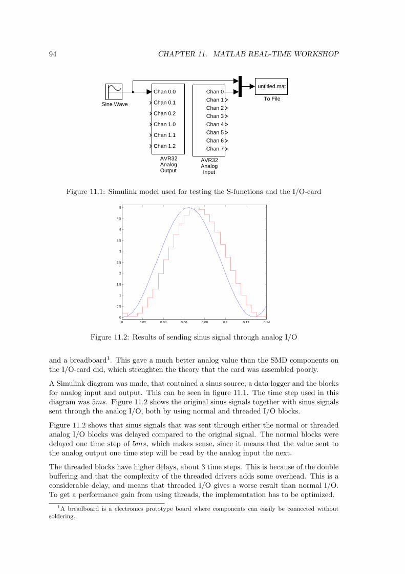
94 CHAPTER 11. MATLAB REAL-TIME WORKSHOP
untitled.mat
To FileSine Wave
Chan 0.0
Chan 0.1
Chan 0.2
Chan 1.0
Chan 1.1
Chan 1.2
AVR32AnalogOutput
Chan 0
Chan 1
Chan 2
Chan 3
Chan 4
Chan 5
Chan 6
Chan 7
AVR32AnalogInput
Figure 11.1: Simulink model used for testing the S-functions and the I/O-card
0 0.02 0.04 0.06 0.08 0.1 0.12 0.14
0
0.5
1
1.5
2
2.5
3
3.5
4
4.5
5
Figure 11.2: Results of sending sinus signal through analog I/O
and a breadboard1. This gave a much better analog value than the SMD components onthe I/O-card did, which strenghten the theory that the card was assembled poorly.
A Simulink diagram was made, that contained a sinus source, a data logger and the blocksfor analog input and output. This can be seen in figure 11.1. The time step used in thisdiagram was 5ms. Figure 11.2 shows the original sinus signals together with sinus signalssent through the analog I/O, both by using normal and threaded I/O blocks.
Figure 11.2 shows that sinus signals that was sent through either the normal or threadedanalog I/O blocks was delayed compared to the original signal. The normal blocks weredelayed one time step of 5ms, which makes sense, since it means that the value sent tothe analog output one time step will be read by the analog input the next.
The threaded blocks have higher delays, about 3 time steps. This is because of the doublebuffering and that the complexity of the threaded drivers adds some overhead. This is aconsiderable delay, and means that threaded I/O gives a worse result than normal I/O.To get a performance gain from using threads, the implementation has to be optimized.
1A breadboard is a electronics prototype board where components can easily be connected withoutsoldering.
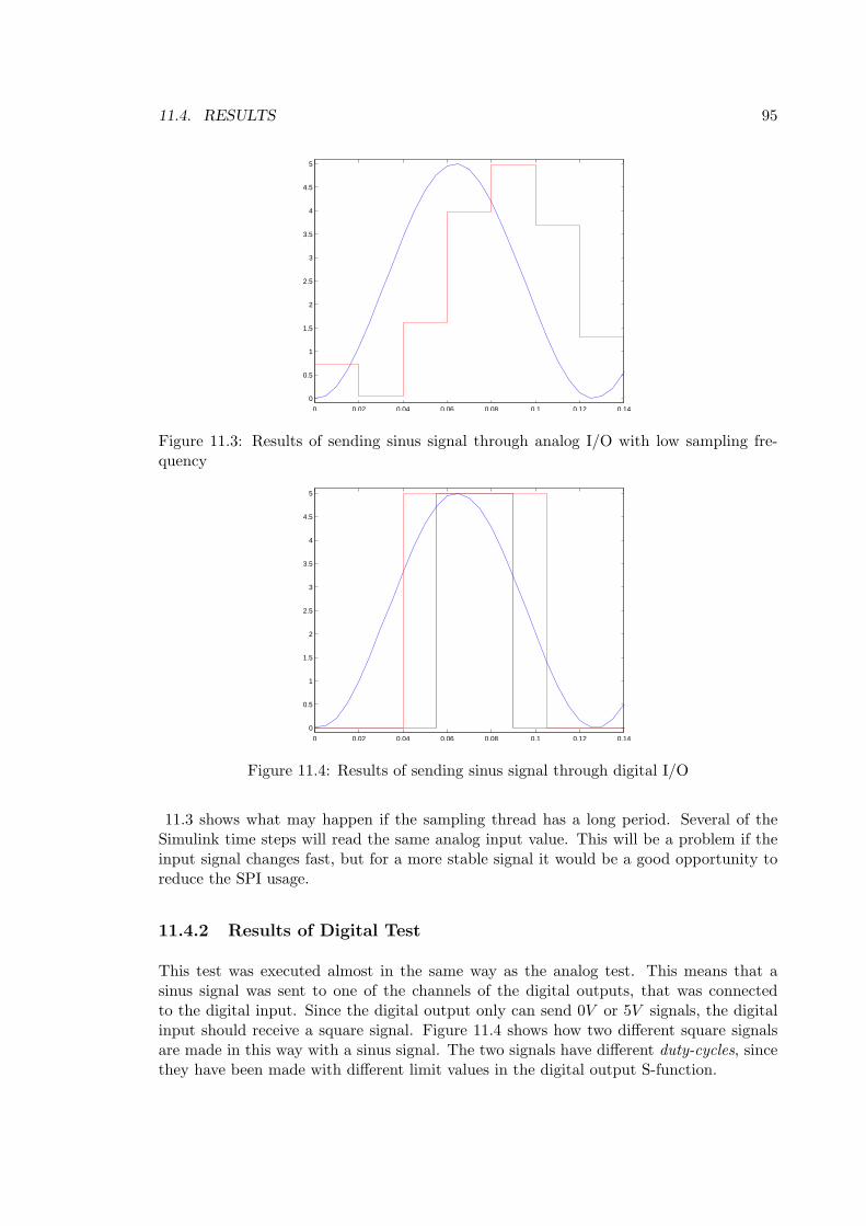
11.4. RESULTS 95
0 0.02 0.04 0.06 0.08 0.1 0.12 0.14
0
0.5
1
1.5
2
2.5
3
3.5
4
4.5
5
Figure 11.3: Results of sending sinus signal through analog I/O with low sampling fre-quency
0 0.02 0.04 0.06 0.08 0.1 0.12 0.14
0
0.5
1
1.5
2
2.5
3
3.5
4
4.5
5
Figure 11.4: Results of sending sinus signal through digital I/O
11.3 shows what may happen if the sampling thread has a long period. Several of theSimulink time steps will read the same analog input value. This will be a problem if theinput signal changes fast, but for a more stable signal it would be a good opportunity toreduce the SPI usage.
11.4.2 Results of Digital Test
This test was executed almost in the same way as the analog test. This means that asinus signal was sent to one of the channels of the digital outputs, that was connectedto the digital input. Since the digital output only can send 0V or 5V signals, the digitalinput should receive a square signal. Figure 11.4 shows how two different square signalsare made in this way with a sinus signal. The two signals have different duty-cycles, sincethey have been made with different limit values in the digital output S-function.

96 CHAPTER 11. MATLAB REAL-TIME WORKSHOP
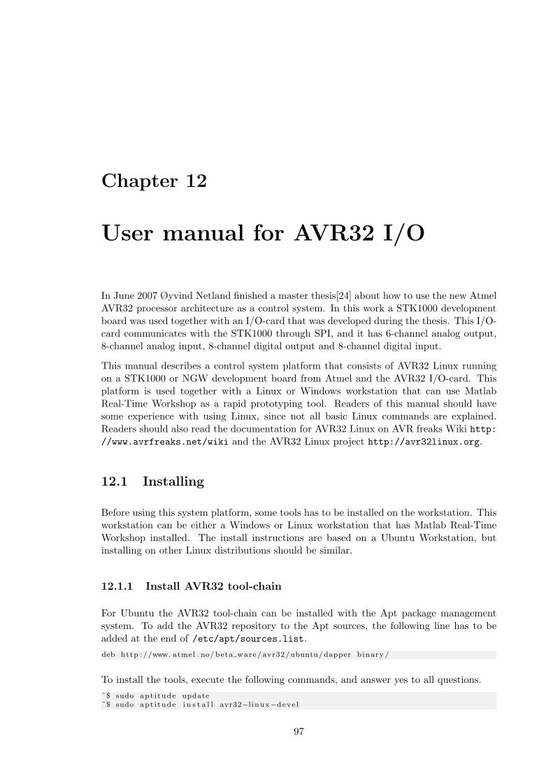
Chapter 12
User manual for AVR32 I/O
In June 2007 Øyvind Netland finished a master thesis[24] about how to use the new AtmelAVR32 processor architecture as a control system. In this work a STK1000 developmentboard was used together with an I/O-card that was developed during the thesis. This I/O-card communicates with the STK1000 through SPI, and it has 6-channel analog output,8-channel analog input, 8-channel digital output and 8-channel digital input.
This manual describes a control system platform that consists of AVR32 Linux runningon a STK1000 or NGW development board from Atmel and the AVR32 I/O-card. Thisplatform is used together with a Linux or Windows workstation that can use MatlabReal-Time Workshop as a rapid prototyping tool. Readers of this manual should havesome experience with using Linux, since not all basic Linux commands are explained.Readers should also read the documentation for AVR32 Linux on AVR freaks Wiki http://www.avrfreaks.net/wiki and the AVR32 Linux project http://avr32linux.org.
12.1 Installing
Before using this system platform, some tools has to be installed on the workstation. Thisworkstation can be either a Windows or Linux workstation that has Matlab Real-TimeWorkshop installed. The install instructions are based on a Ubuntu Workstation, butinstalling on other Linux distributions should be similar.
12.1.1 Install AVR32 tool-chain
For Ubuntu the AVR32 tool-chain can be installed with the Apt package managementsystem. To add the AVR32 repository to the Apt sources, the following line has to beadded at the end of /etc/apt/sources.list.deb http ://www. atmel . no/ beta ware / avr32/ubuntu/dapper binary /
To install the tools, execute the following commands, and answer yes to all questions.˜$ sudo apt i tude update˜$ sudo apt i tude i n s t a l l avr32−l inux−deve l
97
98 CHAPTER 12. USER MANUAL FOR AVR32 I/O
If this approach doesn’t work, or instructions for installing on other platforms, check theAVR freaks Wiki (http://www.avrfreaks.net/wiki).
12.1.2 Compile Linux kernel with AVR32 I/O-card support
This system uses a patched version of the Linux kernel version 2.6.20. The patches neededare the 2.6.20-avr2 patchset from http://www.avr32linux.org and the avr32io patchfrom the CD-ROM. To patch, configure and compile the kernel with AVR32 I/O-cardsupport, Use the commands below from a directory with the Linux source tarball and thetwo patches.˜$ ta r x j f l inux −2 .6 . 20 . ta r . bz2˜$ cd l inux −2.6.20˜$ patch −p1 < . . / l inux −2.6.20− avr2 . patch˜$ patch −p1 < . . / l inux −2.6.20− avr32 io . patch˜$ make ARCH=avr32 CROSS COMPILE=avr32−l inux− menuconfig˜$ make ARCH=avr32 CROSS COMPILE=avr32−l inux−
The second last command will open a menu based configure tool for the Linux kernel. Toenable AVR32 I/O, the Atmel SPI Controller and AVR32 I/O-card has to be enabled.These are both found in device drivers/SPI support. Another solution is to use thelinux-2.6.20-avr32io-config file from the CD-ROM and rename it to .config andmove it to the linux source folder. The last command will compile the kernel and makean uImage, which is the kernel binary file.
To be able to use the AVR32 I/O-card support, the file system of AVR32 Linux needs somedevice nodes for this card. These are made by running a script as root on the workstationcalled mknod.sh that are on the CD-ROM. The script has to be modified to use the correctmajor number and file system path. The major number are printed out during booting,or can be found when running more /proc/devices on AVR32 Linux. The file systempath is the path to the file system of AVR32 Linux, either a SD-card or a shared folderon the workstation.
12.1.3 Install AVR32 support in Matlab
Matlab Real-Time Workshop can generate code that with few modifications can be com-piled for AVR32, but to make it easier to use, a new system target files have been created.These are located on the CD-ROM, in the folder matlab/avr32. The content of thisfolder should be copied into matlab_root/rtw/c/avr32 on the workstation computer,where matlab_root is the folder where Matlab is installed.
When copying the avr32 directory, the subdirectory blocks is also copied. This directorycontain the S-functions that are used to control the I/O-card. These has to be compiledfor Matlab. Start up Matlab and move to the blocks directory. If using Linux, Matlabhas to be started as root. Run the commands below to compile the S-functions.˜$ mex av r32 i o a i n . c˜$ mex avr32 io aout . c˜$ mex avr32 i o d in . c˜$ mex avr32 io dout . c˜$ mex av r32 i o a i n th r ead . c˜$ mex avr32 i o aout th r ead . c
12.2. AVR32 I/O-CARD 99
If this gives an error, the mex compiler has to be configured. The following commandstarts a simple interactive configuration.˜$ mex −s
To use the S-functions in the library, this directory has to be in Matlabs path variable.To add the path use the following commands in Linux, or similar if Matlab is installedsomewhere else.˜$ addpath / usr / l o c a l /matlab/rtw/c/avr32/ b locks˜$ savepath
To add the path when using Windows, the following commands should be used:˜$ addpath c :\Program F i l e s \Matlab\ rtw\c\avr32\ b locks˜$ savepath
Now the S-functions for the I/O-card are available in the library in the blocks directory,and they can be used in other Simulink models.
12.2 AVR32 I/O-card
12.2.1 Hardware description
AVR32 I/O-card is an add-on card for STK1000. It provides the following I/O:
8-channel analog input, with a resolution of 10 bits. The analog value can be between0V − 5V , where 0V equals ground.
6-channel analog output, with a resolution between 8 and 12 bits. 3 of the channelshas output between 0V − 5V , where 0V equals ground. The 3 other channels havejumpers for selecting output type, see 12.2.4.
8-channel digital input.
8-channel digital output.
Figure 12.1 show the front side of the I/O-card, below are a description of the differentparts:
1. Screw clamps for ground and VCC , that gives easy access to these signals.
2. Jumper for selecting if analog output channels 0.0 − 0.2 should have 5V or 10Voutput.
3. Screw clamps for analog output signals.
4. Connector or screw clamp for external power supply. The supply should be between9V and 18V , and the polarity doesn’t matter, because of a bridge rectifier.
5. Jumper for selecting if external power supply or supply from STK1000 should beused.
6. Operational amplifiers used as voltage followers or non-inverting amplifiers.
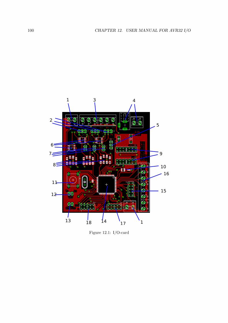
100 CHAPTER 12. USER MANUAL FOR AVR32 I/O
Figure 12.1: I/O-card
12.2. AVR32 I/O-CARD 101
7. Jumpers for bypassing the filter which means that the analog output will become aPWM signal.
8. Passive filters that are used to convert a PWM signal into an analog voltage.
9. Headers for connecting STK1000 or NGW development boards.
10. LC-filter for the analog in power-supply.
11. Reset button
12. UART headers that can be used for debugging.
13. AVR32 interrupt signals, that can be connected to STK1000/NGW if interrupts areused. Not normally used, but might be useful for further development.
14. ATmega128 is the microcontroller that controls the I/O-card.
15. JTAG header for programming and debug ATmega128.
16. Screw clamps for analog input signals.
17. Header for digital input signals.
18. Header for digital output signals.
12.2.2 Connecting I/O-card
The I/O-card connects to either a STK1000 or NGW board through a 14 pin header cable.On STK1000 cards this header cable connects from the header marked STK on the I/O-card, to the general expansion header marked J29 on STK1000. On NGW it connectsfrom the header marked NGW to the general expansion header called J5 on NGW. Onboth boards the header has to be connected to pins 0-13. If interrupts are used, interruptsignals from the I/O-card has to be connected to the STK1000 or NGW boards aswell.
12.2.3 Analog Input
The card has 8 Analog input channels with 10-bit resolution. Each of these can measurean voltage between 0V and 5V above GND. The I/O-card will continuously convertanalog values into digital values and buffer them. Each analog input channel that areused increased the time a value is stored in the buffer before it’s updated by about 110µs.This means that if four channels are used, the values are stored about 440µs before theyare updated.
12.2.4 Analog Output
The card has 2 Analog output channels with 8-bit to 12-bit resolution. Each of thesechannels have 3 subchannels that can have different analog values. The analog outputsare generated with PWM timers and passive filters. This means that a high resolution willgive high ripple on the analog output voltage. Table 12.1 contains the maximum rippleamplitude for different resoultions.
102 CHAPTER 12. USER MANUAL FOR AVR32 I/O
Table 12.1: Rippe for different resolutionsResolution Ripple8-bit 10mV9-bit 20mV10-bit 60mV11-bit 180mV12-bit 500mV
Channel 0 has jumpers that can select the output range of the analog output to be either(0V − 5V ) or (0V − 10V ). And other jumpers that can be used to bypass the filter, so theoutput becomes a PWM signal instead of a analog signal. These jumpers are on the cardto make it possible control as many instruments as possible.
12.3 Rapid prototyping with Matlab Real-Time Workshop
12.3.1 AVR32 System Target
The AVR32 system target are used to easily configure Real-Time Workshop to generateand compile code correctly for rapid prototyping on AVR32. In addition to selecting thissystem target file, some Simulink preferences has to be changed. The solver has to bea fixed-step solver, since the generated code has to use a constant time step. It’s also agood idea to specify the time step, since Matlab might try and use a lower period thanthe AVR32 is able to run. The minimum time step is 1ms, but a complex system has touse a higher time step.
The code automatically logs the average period time, and the average time used for workeach period, and this information will be displayed after completing the simulation. Thismakes it easy to find out if the periods are stable and if the AVR32 are able to completeeach time step inside the period.
12.3.2 S-functions for I/O-card
Four S-functions have been made for each of the four I/O on the card, analog input, analogoutput, digital input and digital output.
The analog input has 8 channels, that gives a value between 0 and 5, which is an analogvoltage between 0V and 5V . Each channel that are connected is an active channel. Thismeans that the generated code will read from the I/O-card, and this takes approximately300µs. If connected, a channel will be read, even if the value isn’t used for anything useful.
The analog output has 2 channels with 3 subchannels each. Each channel can choose aresolution between 8-bit and 12-bit. The I/O-card will give out a voltage between 0V and5V , depending on the value of the S-function blocks input. Each channel connected to thewill be written to each period, and it will use about 250µs.
The digital input has 8 channels, and each channel gives out the value 0 if the channel islow and the value 5 if the channel is high. If any digital input channels are used, it will be
12.3. RAPID PROTOTYPING WITH MATLAB REAL-TIME WORKSHOP 103
read each period and it takes 220µs no matter how many of the channels that are in use.
The digital output has 8 channels, and each channel can be configured with a thresholdvalue. For all values over this threshold the digital output channel will give a voltage of5V , and all values under it will give a voltage of 0V .

104 CHAPTER 12. USER MANUAL FOR AVR32 I/O
Chapter 13
Discussion
The work in this thesis has consisted of developing the hardware and software necessaryfor using the a AVR32 processor in a control system. The work has consisted of severalsmaller tasks, that had to work together. Each of these tasks are discussed separately
13.1 AVR32 Linux
Atmel Norway have done a good job when porting the Linux kernel and development toolsto the AVR32 architecture, but when the work on this thesis began (January 2007), someof the ported software had some problems. Especially AVR32 Linux version 2.6.16 wasproblematic, as described in 3.2. By the end of this thesis (June 2000), both the Linuxkernel version and development tools was more mature and also easy to install on Windowsand on popular Linux distributions like Ubuntu and Fedora.
A small library for making periodic threads and tasks was developed, since control systemneeds to execute work periodically. This library used the Linux timer, which gave accept-able accuracy. The shortest period that was possible to make was 1ms, that turned outto be more than enough because of the speed of the AVR32.
13.2 I/O-card
The I/O-card has an ATmega128 microcontroller that controls everything on the card. Itcommunicates with the AVR32, sets analog and digital output and measure analog anddigital input. Since this component does all this, only a few other components are neededon the card. The disadvantage of using a ATmega128 for analog I/O, is that makingan analog output signal from a PWM-signal isn’t the best solution and it needs manyadditional components like passive filters and operational amplifiers circuits. The ADC(analog input) of the ATmega128 is not the best ADC available.
The analog output part of the I/O-card didn’t work as planned. The prototype card hadworking low-pass filters, but a wrong type of operational amplifiers was used. The finalcard on the other hand had a better type of operational amplifiers, but the low-pass filtersdidn’t work as they should have. The most likely reason for this is that the filters were
105
106 CHAPTER 13. DISCUSSION
poorly assembled. Design of future versions of this card should give the filters more roomto make the assembly easier. Apart from the problems with the analog output, all theparts of the I/O-card worked as planned.
Two different solutions were developed for using the ADC of the ATmega128. The reasonfor this was that the ADC conversion takes a significant amount of time. This was solvedby either interrupting the AVR32 when the ADC conversion was finished, or continuouslyconvert analog values and store them in a buffer. Since the drivers of the I/O-card doesn’tuse threading the continuous mode is the best choice, specially if only some of the Analoginput channels are used. The interrupt mode would be a better choice if a thread wasrunning sending the analog input command, since then the rest of the program could usethe CPU cycles wasted while waiting for the interrupt from the I/O-card.
13.3 I/O-card Communication and Drivers
The communication between the AVR32 and the I/O-card was successfully implementedwith SPI. A protocol was developed for this communication, that the AVR32 uses to givecommands to the I/O-card. This protocol has effective error detection, so both the AVR32and the I/O-card will detect if an error occur. The error detection means that all datapassing between the two processors are returned to the sender for confirmation. This usesthe full duplex capability of SPI, but it still takes longer to send a command than it wouldwithout error detection.
Sending a command to the I/O-card takes between 180µs and 400µs. This is a considerableamount of time, specially if the control system uses small time steps. The main reasonthat sending a command takes this long is that the SPI driver for AVR32. Transferringone byte takes only 2µs, but when sending several bytes after each other, the AVR32 usesat least 9µs between each transfer. If two bytes are sent individually after each other, asmuch as 23µs was used between the transfers.
The SPI driver is obviously not very effective, since so much time is used before andbetween transfers. For the implementation of the I/O-card driver it meant that it wasimportant to try and avoid transferring individual bytes, since this takes longer thansending several bytes at the time.
When testing the SPI communication, almost no commands ended with errors. This meansthat the error detection may not be necessary, since it’s almost never used. By not usingerror detections, the commands would probably be executed faster, since the number oftransfers would be reduced. For special situations where the time used for sending SPImessages has to be as low as possible, this may be a possibility, but normally the errordetection should be used.
It’s also possible that the device driver could be more effective. The User Mode driveropens and closes the device node each time it reads and writes from them, since the devicedriver has mutexes that makes it only possible that one process has it open at the time.This could possibly be made more effective.
13.4. MATLAB REAL-TIME WORKSHOP 107
13.4 Matlab Real-Time Workshop
Matlab Real-Time Workshop was used in this thesis as a rapid prototyping tool. It gen-erates code from Simulink models, that runs on the control system. A new system targetwas created to allow some modifications to the way code are generated. This new systemtarget was able to compile the code for AVR32, and make the code execute periodically.The system target can easily be installed, and are easy to use.
S-functions were developed for the different features of the I/O-card, and it gave Simulinkblocks that was able to control the I/O. The S-functions that uses the normal user modedrivers worked as planned, and they were effective. A test concluded that a value sentthrough the I/O-card only was delayed with one time step. When using the threadeduser mode driver, the results were a longer delay. This means that the threading is a lesseffective solutions. Optimizing the driver might help, but it’s more likely that the increasedoverhead of the threaded driver is bigger than the effectively gain of using threads.

108 CHAPTER 13. DISCUSSION
Chapter 14
Conclusion
This thesis has developed the hardware and software necessary for using the AVR32 pro-cessor architecture as a control system. This resulted in a control system platform thatcan easily be installed and used. The platform it specially suited for applications wherelow weight and power consumption is important, because both the AVR32 itself and themicrocontroller used in the I/O-card are low-power devices.
An I/O-card and drivers were developed and this enabled the AVR32 to measure andcontrol its environment with digital and analog (0V − 5V ) signals. AVR32 communicatesuses SPI to give commands to the I/O-card. This gave a reasonable fast and very reliablecommunication. Since SPI has no error checking, the communication protocol was designedwith an effective error detection, even if the communication itself was reliable. This meansthat in the case of an unlikely error, the system will detect it.
The platform has be configured to use Matlab Real-Time Workshop as a rapid prototypingtool. This tool generates code from Matlab Simulink models, that makes it suited fordesigning and testing different controllers. With the developed S-functions, the I/O-cardcould be controlled with Real-Time Workshop. In this thesis standard Linux timers havebeen used to make the time steps periodical. This gives a minimum period of 1ms, but thishaven’t been a problem since the control system aren’t fast enough to use lower periods.
The platform has some performance limitation. The AVR32 processor isn’t a fast processorcompared to a normal computer, and it lacks a FPU. This means that floating-pointoperations has to be software emulated and is less effective, which limits the ability tocontrol complex systems. If a system is to complex, the risk of breaking any real-timeconstraints increases. However, the platform is well suited to control less complex systems,and the workload is logged, and can be used to detect if the system is close to breaking areal-time constraint.
The user manual was made to make it easy for users to install and use the control systemplatform. For users, the system will function as a black box where they don’t need to knowhow the system works, only that it can be controlled using Matlab Real-Time Workshop.
109

110 CHAPTER 14. CONCLUSION
Chapter 15
Further Work
This thesis has built a control system platform that uses the AVR32 architecture, andfurther work would be to use this platform in a actual control system. The platform mayalso be developed further, to improve it by making it faster and more stable. Below is alist of ideas for further development.
Find ways to make sending commands to the I/O-card more effectively. This can bedone by making the AVR32 Linux SPI driver more efficient, drop error detection orreduce the overhead introduced by it or by optimizing the interaction between theUser Mode driver and the device driver.
Increase the number of I/O protocols that the I/O-card can use. The existing SPIcommunication protocol may be extended to for new commands.
Improve the I/O protocols that are already present.
111

112 CHAPTER 15. FURTHER WORK
Appendix A
Digital appendix
The digital appendix includes the code and other files from the thesis, and have thefollowing directories:
codeContains the code developed in the thesis.
• atmega128Firmware code for the ATmega128.
• avr32Code used by Matlab to make the AVR32 Real-Time target. Contain driversand blocks in subdirectories.
• kernel moduleCode for the device driver as a kernel module.
eagleSchematics and layout of the two AVR32 I/O-card versions in eagle format.
file systemFiles used in the AVR32 file system.
linuxPatches, config files and other AVR32 Linux related files.
reportThe report and the user manual. Subdirectory contain graphics used in the report.
113
Appendix B
Schematics
B.1 Schematic for protoype card
Figure B.1 on the next page is the total schematics for the prototype card.
B.2 Schematic for final card
Figure B.2 on page 116 is the total schematics for the final card.
114
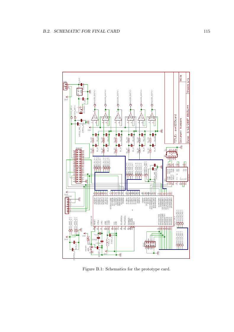
B.2. SCHEMATIC FOR FINAL CARD 115
Figure B.1: Schematics for the prototype card.
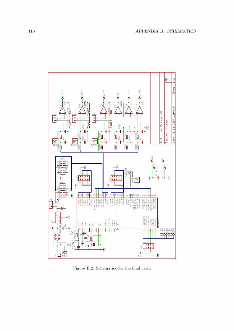
116 APPENDIX B. SCHEMATICS
Figure B.2: Schematics for the final card.
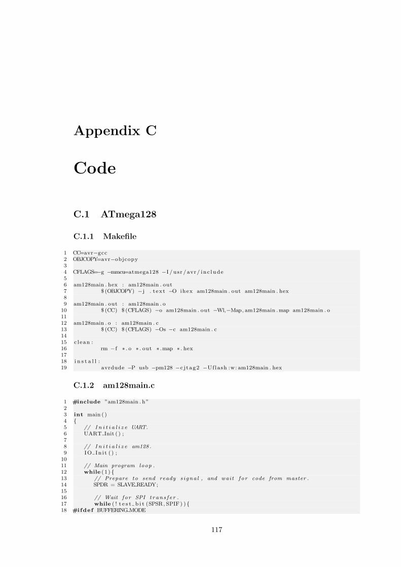
Appendix C
Code
C.1 ATmega128
C.1.1 Makefile
1 CC=avr−gcc2 OBJCOPY=avr−objcopy34 CFLAGS=−g −mmcu=atmega128 −I / usr / avr / inc lude56 am128main . hex : am128main . out7 $ (OBJCOPY) −j . t ex t −O ihex am128main . out am128main . hex89 am128main . out : am128main . o
10 $ (CC) $ (CFLAGS) −o am128main . out −Wl,−Map, am128main .map am128main . o1112 am128main . o : am128main . c13 $ (CC) $ (CFLAGS) −Os −c am128main . c1415 c l ean :16 rm −f ∗ . o ∗ . out ∗ .map ∗ . hex1718 i n s t a l l :19 avrdude −P usb −pm128 −c j t ag2 −Uflash :w: am128main . hex
C.1.2 am128main.c
1 #include ”am128main . h”23 int main ( )4 5 // I n i t i a l i z e UART.6 UART Init ( ) ;78 // I n i t i a l i z e am128 .9 IO In i t ( ) ;
1011 // Main program loop .12 while (1 ) 13 // Prepare to send ready s i gna l , and wait f o r code from master .14 SPDR = SLAVE READY;1516 // Wait f o r SPI t r an s f e r .17 while ( ! t e s t b i t (SPSR, SPIF) ) 18 #ifdef BUFFERING MODE
117
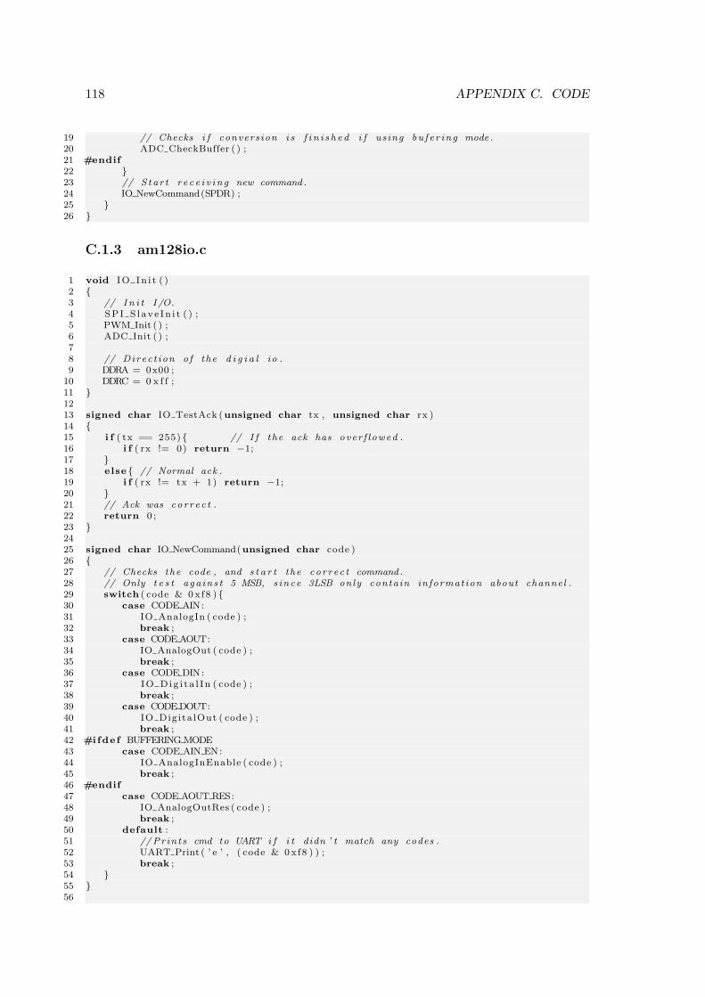
118 APPENDIX C. CODE
19 // Checks i f convers ion i s f i n i s h e d i f us ing bu f e r ing mode .20 ADC CheckBuffer ( ) ;21 #endif22 23 // S tar t r e c e i v i n g new command .24 IO NewCommand(SPDR) ;25 26
C.1.3 am128io.c
1 void IO In i t ( )2 3 // I n i t I /O.4 SPI S l ave In i t ( ) ;5 PWM Init ( ) ;6 ADC Init ( ) ;78 // Direc t ion o f the d i g i a l io .9 DDRA = 0x00 ;
10 DDRC = 0 x f f ;11 1213 signed char IO TestAck (unsigned char tx , unsigned char rx )14 15 i f ( tx == 255) // I f the ack has over f l owed .16 i f ( rx != 0) return −1;17 18 else // Normal ack .19 i f ( rx != tx + 1) return −1;20 21 // Ack was cor r ec t .22 return 0 ;23 2425 signed char IO NewCommand(unsigned char code )26 27 // Checks the code , and s t a r t the cor r ec t command .28 // Only t e s t aga in s t 5 MSB, s ince 3LSB only contain informat ion about channel .29 switch ( code & 0 xf8 ) 30 case CODE AIN:31 IO AnalogIn ( code ) ;32 break ;33 case CODE AOUT:34 IO AnalogOut ( code ) ;35 break ;36 case CODE DIN:37 IO Dig i t a l In ( code ) ;38 break ;39 case CODE DOUT:40 IO Digita lOut ( code ) ;41 break ;42 #ifdef BUFFERING MODE43 case CODE AIN EN:44 IO AnalogInEnable ( code ) ;45 break ;46 #endif47 case CODE AOUT RES:48 IO AnalogOutRes ( code ) ;49 break ;50 default :51 //Prints cmd to UART i f i t didn ’ t match any codes .52 UART Print ( ’ e ’ , ( code & 0 xf8 ) ) ;53 break ;54 55 56
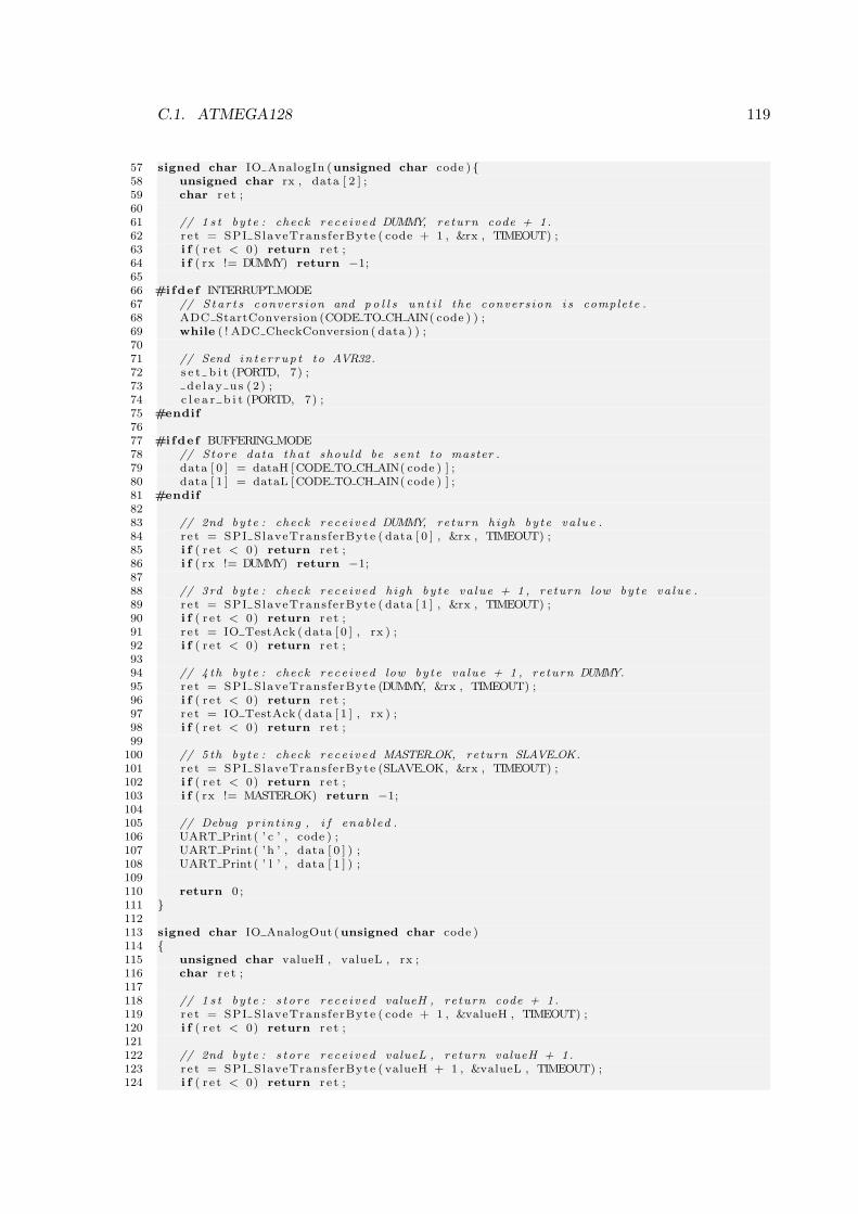
C.1. ATMEGA128 119
57 signed char IO AnalogIn (unsigned char code ) 58 unsigned char rx , data [ 2 ] ;59 char r e t ;6061 // 1 s t by te : check rece i v ed DUMMY, return code + 1.62 r e t = SPI SlaveTrans ferByte ( code + 1 , &rx , TIMEOUT) ;63 i f ( r e t < 0) return r e t ;64 i f ( rx != DUMMY) return −1;6566 #ifdef INTERRUPT MODE67 // S ta r t s convers ion and p o l l s u n t i l the convers ion i s complete .68 ADC StartConversion (CODE TO CH AIN( code ) ) ;69 while ( ! ADC CheckConversion ( data ) ) ;7071 // Send in t e r r up t to AVR32.72 s e t b i t (PORTD, 7) ;73 de l ay u s (2 ) ;74 c l e a r b i t (PORTD, 7) ;75 #endif7677 #ifdef BUFFERING MODE78 // Store data t ha t shou ld be sent to master .79 data [ 0 ] = dataH [CODE TO CH AIN( code ) ] ;80 data [ 1 ] = dataL [CODE TO CH AIN( code ) ] ;81 #endif8283 // 2nd by te : check rece i v ed DUMMY, return high by te va lue .84 r e t = SPI SlaveTrans ferByte ( data [ 0 ] , &rx , TIMEOUT) ;85 i f ( r e t < 0) return r e t ;86 i f ( rx != DUMMY) return −1;8788 // 3rd by te : check rece i v ed high by te va lue + 1 , re turn low by te va lue .89 r e t = SPI SlaveTrans ferByte ( data [ 1 ] , &rx , TIMEOUT) ;90 i f ( r e t < 0) return r e t ;91 r e t = IO TestAck ( data [ 0 ] , rx ) ;92 i f ( r e t < 0) return r e t ;9394 // 4 th by te : check rece i v ed low by te va lue + 1 , re turn DUMMY.95 r e t = SPI SlaveTrans ferByte (DUMMY, &rx , TIMEOUT) ;96 i f ( r e t < 0) return r e t ;97 r e t = IO TestAck ( data [ 1 ] , rx ) ;98 i f ( r e t < 0) return r e t ;99
100 // 5 th by te : check rece i v ed MASTER OK, return SLAVE OK.101 r e t = SPI SlaveTrans ferByte (SLAVE OK, &rx , TIMEOUT) ;102 i f ( r e t < 0) return r e t ;103 i f ( rx != MASTER OK) return −1;104105 // Debug pr in t ing , i f enab led .106 UART Print ( ’ c ’ , code ) ;107 UART Print ( ’h ’ , data [ 0 ] ) ;108 UART Print ( ’ l ’ , data [ 1 ] ) ;109110 return 0 ;111 112113 signed char IO AnalogOut (unsigned char code )114 115 unsigned char valueH , valueL , rx ;116 char r e t ;117118 // 1 s t by te : s t o r e r ece i v ed valueH , re turn code + 1.119 r e t = SPI SlaveTrans ferByte ( code + 1 , &valueH , TIMEOUT) ;120 i f ( r e t < 0) return r e t ;121122 // 2nd by te : s t o r e r ece i v ed valueL , re turn valueH + 1.123 r e t = SPI SlaveTrans ferByte ( valueH + 1 , &valueL , TIMEOUT) ;124 i f ( r e t < 0) return r e t ;
120 APPENDIX C. CODE
125126 // 3rd by te : check rece i v ed DUMMY, return valueL + 1.127 r e t = SPI SlaveTrans ferByte ( valueL + 1 , &rx , TIMEOUT) ;128 i f ( r e t < 0) return r e t ;129 i f ( rx != DUMMY) return −1;130131 // 4 th by te : check rece i v ed MASTER OK, return SLAVE OK.132 r e t = SPI SlaveTrans ferByte (SLAVE OK, &rx , TIMEOUT) ;133 i f ( r e t < 0) return r e t ;134 i f ( rx != MASTER OK) return −1;135136 // When the message i s confirmed the mask and data are app l i ed to d i g i t a l out .137 PWM SetOutValue(CODE TO CH AOUT( code ) , CODE TO SCH AOUT( code ) , valueH , valueL ) ;138139 // Debug pr in t ing , i f enab led .140 UART Print ( ’ c ’ , code ) ;141 UART Print ( ’h ’ , valueH ) ;142 UART Print ( ’ l ’ , valueL ) ;143 144145 signed char IO Dig i t a l In (unsigned char code )146 147 unsigned char rx , va lue ;148 char r e t ;149150 // Only read from the port once during communication151 value = PINA;152153 // 1 s t by te : check rece i v ed DUMMY, return code + 1.154 r e t = SPI SlaveTrans ferByte ( code + 1 , &rx , TIMEOUT) ;155 i f ( r e t < 0) return r e t ;156 i f ( rx != DUMMY) return −1;157158 // 2nd by te : check rece i v ed DUMMY, return va lue .159 r e t = SPI SlaveTrans ferByte ( value , &rx , TIMEOUT) ;160 i f ( r e t < 0) return r e t ;161 i f ( rx != DUMMY) return −1;162163 // 3rd by te : check rece i v ed va lue + 1 , re turn DUMMY.164 r e t = SPI SlaveTrans ferByte (DUMMY, &rx , TIMEOUT) ;165 i f ( r e t < 0) return r e t ;166 r e t = IO TestAck ( value , rx ) ;167 i f ( r e t < 0) return r e t ;168169 // 4 th by te : check rece i v ed MASTER OK, return SLAVE OK.170 r e t = SPI SlaveTrans ferByte (SLAVE OK, &rx , TIMEOUT) ;171 i f ( r e t < 0) return r e t ;172 i f ( rx != MASTER OK) return −1;173174 // Debug pr in t ing , i f enab led .175 UART Print ( ’ c ’ , code ) ;176 UART Print ( ’ v ’ , va lue ) ;177178 return 0 ;179 180181 signed char IO Digita lOut (unsigned char code )182 183 unsigned char mask , value , rx ;184 char ret , i ;185186 // 1 s t by te : s t o r e r ece i v ed mask , re turn code + 1.187 r e t = SPI SlaveTrans ferByte ( code + 1 , &mask , TIMEOUT) ;188 i f ( r e t < 0) return r e t ;189190 // 2nd by te : s t o r e r ece i v ed value , re turn mask + 1.191 r e t = SPI SlaveTrans ferByte (mask + 1 , &value , TIMEOUT) ;192 i f ( r e t < 0) return r e t ;
C.1. ATMEGA128 121
193194 // 3rd by te : check rece i v ed DUMMY, return va lue + 1.195 r e t = SPI SlaveTrans ferByte ( va lue + 1 , &rx , TIMEOUT) ;196 i f ( r e t < 0) return r e t ;197 i f ( rx != DUMMY) return −1;198199 // 4 th by te : check rece i v ed MASTER OK, return SLAVE OK.200 r e t = SPI SlaveTrans ferByte (SLAVE OK, &rx , TIMEOUT) ;201 i f ( r e t < 0) return r e t ;202 i f ( rx != MASTER OK) return −1;203204 // When the message i s confirmed the mask and data are app l i ed to d i g i t a l out .205 for ( i =0; i <8; i++)206 i f ( t e s t b i t (mask , i ) ) 207 i f ( t e s t b i t ( value , i ) ) s e t b i t (PORTC, i ) ;208 else c l e a r b i t (PORTC, i ) ;209 210 211212 // Debug pr in t ing , i f enab led .213 UART Print ( ’ c ’ , code ) ;214 UART Print ( ’m’ , mask ) ;215 UART Print ( ’ v ’ , va lue ) ;216 217218 #ifdef BUFFERING MODE219 signed char IO AnalogInEnable (unsigned char code )220 221 unsigned char enable , rx ;222 char r e t ;223224 // 1 s t by te : s t o r e r ece i v ed enable , re turn code + 1.225 r e t = SPI SlaveTrans ferByte ( code + 1 , &enable , TIMEOUT) ;226 i f ( r e t < 0) return r e t ;227228 // 2nd by te : s t o r e r ece i v ed DUMMY, return enab le + 1.229 r e t = SPI SlaveTrans ferByte ( enable + 1 , &rx , TIMEOUT) ;230 i f ( r e t < 0) return r e t ;231 i f ( rx != DUMMY) return −1;232233 // 3rd by te : check rece i v ed MASTER OK, return SLAVE OK.234 r e t = SPI SlaveTrans ferByte (SLAVE OK, &rx , TIMEOUT) ;235 i f ( r e t < 0) return r e t ;236 i f ( rx != MASTER OK) return −1;237238 // When the message i s confirmed the channel are enab led or d i s a b l e d .239 i f ( enable == 0) 240 ADC DisableChan (CODE TO CH AIN( code ) ) ;241 242 else 243 ADC EnableChan(CODE TO CH AIN( code ) ) ;244 245246 // Debug pr in t ing , i f enab led .247 UART Print ( ’ c ’ , code ) ;248 UART Print ( ’ e ’ , enable ) ;249 250 #endif251252 signed char IO AnalogOutRes (unsigned char code )253 254 unsigned char r e s o l u t i on , chEnable , rx ;255 char r e t ;256257 // 1 s t by te : s t o r e r ece i v ed re so l u t i on , re turn code + 1.258 r e t = SPI SlaveTrans ferByte ( code + 1 , &r e s o l u t i on , TIMEOUT) ;259 i f ( r e t < 0) return r e t ;260
122 APPENDIX C. CODE
261 // 2nd by te : check rece i v ed DUMMY, return r e s o l u t i on + 1.262 r e t = SPI SlaveTrans ferByte ( r e s o l u t i o n + 1 , &rx , TIMEOUT) ;263 i f ( r e t < 0) return r e t ;264 i f ( rx != DUMMY) return −1;265266 // 3rd by te : check rece i v ed MASTER OK, return SLAVE OK.267 r e t = SPI SlaveTrans ferByte (SLAVE OK, &rx , TIMEOUT) ;268 i f ( r e t < 0) return r e t ;269 i f ( rx != MASTER OK) return −1;270271 // When the message i s confirmed the analog out r e s o l u t i on o f the s e l e c t e d
channel w i l l be updated .272 PWM SetResolution (CODE TO CH AOUT( code ) , r e s o l u t i o n ) ;273274 // Debug pr in t ing , i f enab led .275 UART Print ( ’ c ’ , code ) ;276 UART Print ( ’ r ’ , r e s o l u t i o n ) ;277
C.1.4 am128spiSlave.c
1 void SPI S l ave In i t (void )2 3 // Enables SPI and s e t s the MISO s i g na l as an output .4 SPCR = (1<<SPE) ;5 DDRB = (1<<3) ;67 // Timer p r e s ca l e r 256 (16 us ) .8 #ifdef TIMEOUT ENABLE9 TCCR0 = (1 << CS02) | (1 << CS01) ;
10 #endif11 1213 signed char SPI SlaveTrans ferByte (unsigned char tx , unsigned char ∗ rx , unsigned
char usec )14 15 #ifdef TIMEOUT ENABLE16 // S ta r t s t imer .17 TCNT0 = 0 ;18 #endif1920 // Prepare data to send and wait f o r SPI t r an s f e r from master .21 SPDR = tx ;22 while ( ! ( SPSR & (1<<SPIF) ) ) 23 #ifdef TIMEOUT ENABLE24 // Checks f o r t imeout .25 i f (TCNT0 > usec ) return −1;26 #endif27 2829 // Returns data .30 ∗( rx ) = SPDR;31 return 0 ;32
C.1.5 am128adc.c
12 void ADC Init ( )3 4 // Direc t ion o f adc channels .5 DDRF = 0 ;67 #ifdef INTERRUPT MODE8 // Direc t ion o f i n t e r r up t .9 s e t b i t (DDRD, 7) ;
C.1. ATMEGA128 123
10 c l e a r b i t (PORTD, 7) ;11 #endif1213 // I n i t i a l i z e ADC.14 ADMUX = (1<<REFS0) ;15 ADCSRA = (1<<ADEN) | (1<<ADPS2) | (1<<ADPS1) | (1<<ADPS0) ;16 1718 #ifdef BUFFERING MODE19 void ADC EnableChan(char channel )20 21 char i ;22 struct chanList ∗temp , ∗temp2 ;2324 i f ( chCount == 0) 25 // Make t a b l e element and s t a r t conver t ing .26 channe l s = ( channeltab + channel ) ;27 channels−>next = channe l s ;28 channels−>prev = channe l s ;29 channels−>channel = channel ;30 ADC NewConversion ( ) ;31 32 else 33 // Search through channels and check i f the channel i s a l ready enab led .34 temp = channe l s ;35 for ( i =0; i<chCount ; i++)36 // I f channel a l ready i s enab led the func t i on ends .37 i f ( temp−>channel == channel ) return ;38 temp = temp−>next ;39 4041 // Make new channel .42 temp = ( channeltab + channel ) ;43 temp−>channel = channel ;4445 // In s e r t s new channel in l i s t .46 temp−>next = channels−>next ;47 temp−>prev = channe l s ;48 channels−>next = temp ;49 channels−>next−>prev = temp ;50 5152 // Increase number o f channels ;53 chCount++;54 5556 void ADC DisableChan (char channel )57 58 char i , enabled ;59 struct chanList ∗temp ;6061 temp = channe l s ;62 enabled = 0 ;6364 // Search through channels and check i f the channel i s enab led .65 for ( i =0; i<chCount ; i++)66 i f ( temp−>channel == channel ) 67 enabled = 1 ;68 break ;69 70 temp = temp−>next ;71 72 // I f channel aren ’ t enab led the func t i on ends .73 i f ( enabled == 0) return ;7475 // Update po in t e r s i n s i d e the l i s t .76 temp−>prev−>next = temp−>next ;77 temp−>next−>prev = temp−>prev ;
124 APPENDIX C. CODE
78 chCount−−;7980 i f ( chCount == 0) ADC StopConversion ( ) ;81 8283 void ADC CheckBuffer ( )84 85 i f ( t e s t b i t (ADCSRA, ADIF) ) 86 // Stor ing new data .87 dataL [ channels−>channel ] = ADCL;88 dataH [ channels−>channel ] = ADCH;8990 // S tar t new convers ion .91 ADC NewConversion ( ) ;92 93 9495 void ADC NewConversion ( )96 97 channe l s = channels−>next ;9899 ADMUX = ADMUX & 0xe0 ;
100 ADMUX = ADMUX | channels−>channel ;101102 // S ta r t convers ion .103 s e t b i t (ADCSRA, ADSC) ;104 105106 void ADC StopConversion ( )107 108 c l e a r b i t (ADCSRA, ADSC) ;109 110 #endif111112 #ifdef INTERRUPT MODE113 void ADC StartConversion (char channel )114 115 ADMUX = ADMUX & 0xe0 ;116 ADMUX = ADMUX | channel ;117118 // S ta r t convers ion .119 s e t b i t (ADCSRA, ADSC) ;120 121122 signed char ADC CheckConversion (unsigned char ∗data )123 124 i f ( t e s t b i t (ADCSRA, ADIF) ) 125 // Clear s t a t u s b i t .126 s e t b i t (ADCSRA, ADIF) ;127128 // Stor ing new data .129 data [ 1 ] = ADCL;130 data [ 0 ] = ADCH;131132 // Finished .133 return 1 ;134 135 // Not f i n i s h e d .136 return 0 ;137 138 #endif
C.1.6 am128pwm.c
1 void PWM Init ( )2 3 // Set the PWM por t s as output
C.1. ATMEGA128 125
4 s e t b i t (DDRE, 3) ;5 s e t b i t (DDRE, 4) ;6 s e t b i t (DDRE, 5) ;7 s e t b i t (DDRB, 5) ;8 s e t b i t (DDRB, 6) ;9 s e t b i t (DDRB, 7) ;
1011 // Set the con t ro l r e g i s t e r s f o r PWM to f a s t PWM, with no p r e s ca l e r and c l e a r
output on compare match (non−i n v e r t i n g mode) .12 TCCR1A =(1<<COM1A1) | (1<<COM1B1) | (1<<COM1C1) | (1<<WGM11) ;13 TCCR1B = (1<<WGM13) | (1<<WGM12) | (1<<CS10) ;1415 TCCR3A =(1<<COM3A1) | (1<<COM3B1) | (1<<COM3C1) | (1<<WGM31) ;16 TCCR3B = (1<<WGM33) | (1<<WGM32) | (1<<CS30) ;1718 // Set both PWM to have 8− b i t r e s o l u t i on .19 PWM SetResolution (0 , 8 ) ;20 PWM SetResolution (1 , 8 ) ;2122 // Set a l l PWM−outputs to zero .23 PWM SetOutValue (0 , 1 , 0x00 , 0x00 ) ;24 PWM SetOutValue (0 , 2 , 0x00 , 0x00 ) ;25 PWM SetOutValue (0 , 3 , 0x00 , 0x00 ) ;26 PWM SetOutValue (1 , 1 , 0x00 , 0x00 ) ;27 PWM SetOutValue (1 , 2 , 0x00 , 0x00 ) ;28 PWM SetOutValue (1 , 3 , 0x00 , 0x00 ) ;29 3031 void PWM SetOutValue(char ch , char sch , char valueH , char valueL )32 33 // Checks which PWM/timer tha t shou ld be s e t . Ei ther 0 or 1 .34 switch ( ch ) 35 case 0 :36 // Checks what channel o f the PWM/timer . A=1, B=2 and C=3.37 switch ( sch ) 38 case 0 :39 OCR1AH = valueH ;40 OCR1AL = valueL ;41 break ;42 case 1 :43 OCR1BH = valueH ;44 OCR1BL = valueL ;45 break ;46 case 2 :47 OCR1CH = valueH ;48 OCR1CL = valueL ;49 break ;50 51 break ;52 case 1 :53 // Checks what channel o f the PWM/timer . A=1, B=2 and C=3.54 switch ( sch ) 55 case 0 :56 OCR3AH = valueH ;57 OCR3AL = valueL ;58 break ;59 case 1 :60 OCR3BH = valueH ;61 OCR3BL = valueL ;62 break ;63 case 2 :64 OCR3CH = valueH ;65 OCR3CL = valueL ;66 break ;67 68 break ;69 70
126 APPENDIX C. CODE
7172 void PWM SetResolution (char ch , char r e s o l u t i o n )73 74 char resH , resL , i ;75 resH = 0x00 ;76 resL = 0x00 ;7778 // Finds va lue s f o r the ICRn r e g i s t e r s t ha t g i v e s the reques t ed r e s o l u t i on .79 i f ( r e s o l u t i o n <= 8) // For r e s o l u t i on equa l or l e s s than 8− b i t s .80 for ( i =0; i<r e s o l u t i o n ; i++)81 s e t b i t ( resL , i ) ;82 83 84 else // For r e s o l u t i on over 8− b i t s .85 resL = 0 x f f ;86 for ( i =0; i<r e s o l u t i on −8; i++)87 s e t b i t ( resH , i ) ;88 89 9091 // Writes the va lue s to the r i g h t ICRn r e g i s t e r .92 switch ( ch ) 93 case 0 :94 ICR1H = resH ;95 ICR1L = resL ;96 break ;97 case 1 :98 ICR3H = resH ;99 ICR3L = resL ;
100 break ;101 102103 // Sets output on a l l subchanne ls to zero .104 PWM SetOutValue( ch , 1 , 0x00 , 0x00 ) ;105 PWM SetOutValue( ch , 2 , 0x00 , 0x00 ) ;106 PWM SetOutValue( ch , 3 , 0x00 , 0x00 ) ;107
C.1.7 am128uart.c
1 void UART Init ( )2 3 #ifdef RS232 DEBUG4 // Set d i r e c t i on r e g i s t e r s .5 s e t b i t (DDRD, 3) ;6 c l e a r b i t (DDRD, 2) ;78 // BAUD rate = 19.2 k .9 UBRR1H = 0 ;
10 UBRR1L = 51 ;1112 // Enable both transmit and r e c e i v e .13 UCSR1B = (1<<RXEN1) | (1<<TXEN1) ;1415 // Use 8 b i t data , no pa r i t y and 2 s top b i t s .16 UCSR1C = (1<<UCSZ11) | (1<<UCSZ10) | (1<<USBS1) ;17 #endif18 1920 void UART TxByte(char data )21 22 #ifdef RS232 DEBUG23 // Wait u n t i l l a s t message i s sent , then send t h i s one .24 l o o p b i t i s s e t (UCSR1A, UDRE1) ;25 UDR1=data ;26 #endif27

C.1. ATMEGA128 127
2829 void UART TxSpace ( )30 31 #ifdef RS232 DEBUG32 UART TxByte(32) ;33 #endif34 3536 void UART TxNewLine ( )37 38 #ifdef RS232 DEBUG39 UART TxByte( ’ \n ’ ) ;40 UART TxByte( ’ \ r ’ ) ;41 #endif42 434445 void UART TxDecimal (unsigned char value )46 47 #ifdef RS232 DEBUG48 char tx [ 3 ] , i ;4950 // tx [ 0 ]51 tx [ 0 ] = ’ 0 ’ ;52 for ( i =0; i <3; i++)53 i f ( va lue > 99) 54 tx [ 0 ] = tx [ 0 ] + 1 ;55 value = value − 100 ;56 57 5859 // tx [ 1 ]60 tx [ 1 ] = ’ 0 ’ ;61 for ( i =0; i <10; i++)62 i f ( va lue > 9) 63 tx [ 1 ] = tx [ 1 ] + 1 ;64 value = value − 10 ;65 66 6768 // tx [ 2 ]69 tx [ 2 ] = ’ 0 ’ ;70 for ( i =0; i <10; i++)71 i f ( va lue > i ) 72 tx [ 2 ] = tx [ 2 ] + 1 ;73 74 7576 //Print77 for ( i =0; i <3; i++)78 UART TxByte( tx [ i ] ) ;79 80 #endif81 8283 void UART Print (char symbol , unsigned char value )84 85 #ifdef RS232 DEBUG86 UART TxByte( symbol ) ;87 UART TxByte( ’ : ’ ) ;88 UART TxSpace ( ) ;89 UART TxDecimal ( va lue ) ;90 UART TxNewLine ( ) ;91 #endif92
128 APPENDIX C. CODE
C.2 Kernel module
C.2.1 Makefile
1 # Inc lude the AVR32 header f i l e s2 CFLAGS += −I / usr / l o c a l /avr32−l i nux / inc lude3 CFLAGS += −D AVR32 AP700045 MAKE := make ARCH=avr32 CROSS COMPILE=avr32−l inux−6 KERNELDIR := /home/oyvindne/diplom/ source / l i nux7 PWD := $ ( s h e l l pwd)89 obj−m := avr32 io . o
1011 d e f au l t :12 $ (MAKE) −C $ (KERNELDIR) M=$ (PWD) modules1314 c l ean :15 rm −f ∗ . o ∗ . ko ∗ .mod.∗ .∗cmd core16 rm −r f . tmp vers ions1718 i n s t a l l :19 cp avr32 io . ko /home/oyvindne/diplom/ f s / avr32 io . ko
C.2.2 avr32ioc
1 #include ”avr32 io . h”23 stat ic int i n i t a v r 3 2 i o I n i t (void )4 5 int r e t ;67 i f ( ! ( dev i c e = k z a l l o c ( s izeof ( struct av r32 i o d ev i c e ) , GFP KERNEL) ) )8 9 pr in tk (KERN ALERT ”av r 3 2 i o I n i t : k z a l l o c f a i l e d \n”) ;
10 return −ENOMEM;11 1213 // Major/minor number a l l o c a t i o n14 r e t = a l l o c c h r d e v r e g i o n (&device−>number , 0 , COUNT TOTAL, ”avr32 io ”) ;15 i f ( r e t < 0) 16 pr in tk (KERN ALERT ”av r 3 2 i o I n i t : a l l o c c h r d e v r e g i o n f a i l e d %i \n” , r e t ) ;17 goto errRegion ;18 1920 // Adding cdev .21 device−>charDevice = cd ev a l l o c ( ) ;22 device−>charDevice−>ops = &fops ;23 device−>charDevice−>owner = THIS MODULE;24 r e t = cdev add ( device−>charDevice , device−>number , COUNT TOTAL) ;25 i f ( r e t < 0) 26 pr in tk (KERN ALERT ”av r 3 2 i o I n i t : charDevice f a i l e d %i \n” , r e t ) ;27 goto errCharDevice ;28 2930 // Reg i s t ra t i on o f the d r i v e r with the l i nux dev i ce model31 r e t = s p i r e g i s t e r d r i v e r (&av r 3 2 i o d r i v e r ) ;32 i f ( r e t < 0) 33 pr in tk (KERN ALERT ”av r 3 2 i o I n i t : s p i r e g i s t e r d r i v e r f a i l e d %i \n” , r e t ) ;34 goto errRegDriver ;35 3637 #ifdef INTERRUPT MODE38 // Reg i s t ra t i on o f IRQ39 r e t = r e qu e s t i r q (EIM IRQ BASE , irqFunk , IRQF TRIGGER RISING, ”av r 3 2 i o i n t e r r up t
” , NULL) ;
C.2. KERNEL MODULE 129
40 i f ( r e t < 0) 41 DEBUG( ”avr IO In i t : r e q u e s t i r q f a i l e d %i \n” , r e t ) ;42 goto errRegIRQ ;43 44 device−>i rqID = re t ;45 #endif4647 pr in tk (KERN INFO ”av r 3 2 i o I n i t : s u c e s s f u l l major : %i \n” , MAJOR( device−>number ) ) ;4849 //Return s u c e s s f u l l50 return 0 ;5152 //Error , r o l l back re sourse s .53 #ifdef INTERRUPT MODE54 errRegIRQ :55 s p i u n r e g i s t e r d r i v e r (&av r 3 2 i o d r i v e r ) ;56 #endif57 errRegDriver :58 cdev de l ( device−>charDevice ) ;59 errCharDevice :60 un r e g i s t e r c h rd ev r e g i on ( device−>number , 4) ;61 errRegion :62 k f r e e ( dev i ce ) ;63 return r e t ;64 6566 stat ic void e x i t av r32 i o Ex i t (void )67 68 #ifdef INTERRUPT MODE69 // Free the IRQ.70 f r e e i r q (EIM IRQ BASE ,NULL) ;71 #endif7273 // Unreg i s ter the d r i v e r from the l i nux dev i ce model74 s p i u n r e g i s t e r d r i v e r (&av r 3 2 i o d r i v e r ) ;7576 // Unreg i s ter the charac ter dev i ce from the ke rne l77 cdev de l ( device−>charDevice ) ;7879 // Unreg i s ter major/minor numbers a l l o c a t e d80 un r e g i s t e r c h rd ev r e g i on ( device−>number , COUNT TOTAL) ;8182 // Free memory used by the dev i ce s t r u c t .83 k f r e e ( dev i c e ) ;8485 pr in tk (KERN INFO ”avr32 i o Ex i t : module e x i t \n”) ;86 8788 stat ic int d e v i n i t avr32 io Probe ( struct s p i d e v i c e ∗ s p i )89 90 int r e t ;9192 // I n i t i a l i z e the sp i s t r u c t93 device−>s p i = sp i ;94 spi−>mode = SPI MODE 0 ;95 spi−>b i t s pe r word = 0x08 ; // 8− b i t s per t r an s f e r .96 spi−>max speed hz = 2100000; // h i g h e s t va lue t ha t works i s 2100000 @ 16MHz97 spi−>c h i p s e l e c t = 0x02 ; // Uses s l a v e number 2 .9899 // Setup the SPI d r i v e r and channel
100 r e t = sp i s e t up ( sp i ) ;101 i f ( r e t < 0) 102 pr in tk (KERN ALERT ”avr32 io Probe : s p i s e t up f a i l e d %d\n” , r e t ) ;103 return r e t ;104 105106 dev se t drvdata (&spi−>dev , dev i c e ) ;107 return 0 ;
130 APPENDIX C. CODE
108 109110 stat ic int avr32io Open ( struct inode ∗node , struct f i l e ∗ f i l p )111 112 int minor , r e t ;113114 minor = iminor ( f i l p −>f dent ry−>d inode ) ;115 DEBUG( ”avr32io Open : minor %i \n” , minor ) ;116117 // Take mutex .118 r e t = down in t e r rupt ib l e (&spiMutex ) ;119 i f ( r e t < 0) return −ERESTARTSYS;120121 // Check i f SPI i s used .122 i f ( device−>busy == 0) 123 // SPI busy , re turn error .124 r e t = −EBUSY;125 126 else 127 // SPI not busy , mark as busy and return success .128 device−>busy == 1 ;129 r e t = 0 ;130 131132 // Returns the mutex and return i f the SPI was busy or not .133 up(&spiMutex ) ;134 return r e t ;135 136137 stat ic int avr32 i o Re l ea s e ( struct inode ∗node , struct f i l e ∗ f i l p )138 139 DEBUG( ”avr32 i o Re l ea s e \n”) ;140141 // Take mutex .142 r e t = down in t e r rupt ib l e (&spiMutex ) ;143 i f ( r e t < 0) return −ERESTARTSYS;144145 // Mark the SPI as not busy .146 device−>busy == 0 ;147148 // Returns the mutex and re turns success .149 up(&spiMutex ) ;150 return 0 ;151 152153 stat ic s s i z e t avr32io Read ( struct f i l e ∗ f i l p , char u s e r ∗userBuf , s i z e t len ,
l o f f t ∗ f p o s )154 155 int r e t ;156 u8 toUser [ l en ] ;157 int minor = iminor ( f i l p −>f dent ry−>d inode ) ;158159 DEBUG( ”avr32io Read : minor %i i sAin : %i i sDin : %i \n” , minor , IS AIN ( minor ) ,
IS DIN ( minor ) ) ;160161 i f ( IS AIN ( minor ) ) //Analog In162 i f ( l en != 2) return −EPERM;163 r e t = Cmd GetAIn( toUser , MinorToChAin ( minor ) ) ;164 i f ( r e t < 0) return r e t ;165 copy to use r ( userBuf , toUser , l en ) ;166 return l en ;167 168169 i f ( IS DIN ( minor ) ) // D i g i t a l In170 i f ( l en != 1) return −EPERM;171 r e t = Cmd GetDIn( toUser ) ;172 i f ( r e t < 0) return r e t ;173 copy to use r ( userBuf , toUser , l en ) ;
C.2. KERNEL MODULE 131
174 return l en ;175 176177 // I f no output matches the minor number the wr i t e operat ion f a i l s .178 return −EPERM;179 180181 stat ic s s i z e t avr32 io Wri te ( struct f i l e ∗ f i l p , const char u s e r ∗userBuf , s i z e t
len , l o f f t ∗ f p o s )182 183 u8 fromUser [ l en ] ;184 int minor = iminor ( f i l p −>f dent ry−>d inode ) ;185186 copy from user (&fromUser , userBuf , l en ) ;187188 DEBUG( ”avr32 io Wri te : minor %i isAout : %i isDout : %i \n” , minor , IS AOUT( minor ) ,
IS DOUT( minor ) ) ;189190 i f (IS AOUT( minor ) ) //Analog Out191 i f ( l en != 3) return −EPERM;192 i f (Cmd SetAOut( fromUser + 1 , MinorToChAout ( minor ) , fromUser [ 0 ] ) >= 0) 193 return l en ;194 195 196197 i f (IS DOUT( minor ) ) // D i g i t a l Out198 i f ( l en != 2) return −EPERM;199 i f (Cmd SetDOut( fromUser ) >= 0) 200 return l en ;201 202 203204 // I f no output matches the minor number the wr i t e operat ion f a i l s .205 return −EPERM;206 207208 stat ic int a v r 3 2 i o I o c t l ( struct inode ∗node , struct f i l e ∗ f i l p , unsigned int cmd ,
unsigned long arg )209 210 int minor = iminor ( f i l p −>f dent ry−>d inode ) ;211212 DEBUG( ”a v r 3 2 i o I o c t l : i o c t l minor : %i cmd : %i isAout : %i i sAin : %i \n” , minor ,
cmd , IS AOUT( minor ) , IS AIN ( minor ) ) ;213214 switch (cmd) 215 case AVR32IO IOCTL RES AOUT: // Change r e s o l u t i on on a analog channel .216 i f (IS AOUT( minor ) ) 217 return Cmd SetAOutResolution ( ( u8 ) ( arg ) , MinorToChAout ( minor ) ) ;218 219 #ifdef BUFFERING MODE220 case AVR32IO IOCTL EN AIN : // Enables or d i s a b l e s analog in .221 i f ( IS AIN ( minor ) ) 222 return Cmd EnableAIn ( ( u8 ) ( arg ) , MinorToChAin ( minor ) ) ;223 224 #endif225 226227 // I f cmd i s not a v a l i d command .228 return −ENOIOCTLCMD;229
C.2.3 avr32io Cmd.c
12 int Cmd WaitForAM128( u8 code )3 4 int count = 0 ;
132 APPENDIX C. CODE
5 u8 ready ;67 // Loops u n t i l i t r e c e i v e s the co r r ec t code from ATMega128 .8 while ( ready != SLAVE READY) 9 SPI MasterTransfer (&ready , &code , 1) ;
10 i f ( count++ > 100) return −EIO ;11 12 return count ;13 1415 int Cmd GetAIn( u8 ∗ toUser , int ch )16 17 int r e t ;1819 // check f o r v a l i d channel .20 i f ( ch < 0) return −EIO ;2122 // Synchronize with ATMega12823 r e t = Cmd WaitForAM128(CH TO CODE AIN( ch ) ) ;24 DEBUG( ”code : %i count : %i \n” , CH TO CODE AIN( ch ) , r e t ) ;25 i f ( r e t < 0) return r e t ;2627 // Send DUMMY, re c e i v e code ack .28 r e t = SPI MasterTransferByte (DUMMY) ;29 DEBUG( ”dummy: %i code+1: %i \n” , DUMMY, r e t ) ;30 i f ( r e t != CH TO CODE AIN( ch ) + 1) return −EIO ;3132 #ifdef INTERRUPT MODE33 // Wait f o r i n t e r r up t .34 device−>i r qF lag = 0 ;35 DEBUG( ”wait \n”) ;36 r e t = wa i t e v en t i n t e r r up t i b l e t imeou t (wq , device−>i r qF lag != 0 , 10000) ;37 i f ( r e t < 0) return −ERESTARTSYS;38 DEBUG( ” i n t e r r up t \n”) ;39 #endif4041 // Send DUMMY, re c e i v e data0 .42 r e t = SPI MasterTransferByte (DUMMY) ;43 DEBUG( ”dummy: %i data0 : %i \n” , DUMMY, r e t ) ;44 i f ( r e t < 0) return r e t ;45 toUser [ 0 ] = (u8 ) r e t ;4647 // Send data0 ack , r e c e i v e data1 .48 r e t = SPI MasterTransferByte ( ( u8 ) ( toUser [ 0 ] + 1) ) ;49 DEBUG( ”data0+1: %i data1 : %i \n” , ( ( u8 ) ( toUser [ 0 ] ) + 1) , r e t ) ;50 i f ( r e t < 0) return r e t ;51 toUser [ 1 ] = (u8 ) r e t ;5253 // Send data1 ack , r e c e i v e DUMMY.54 r e t = SPI MasterTransferByte ( ( u8 ) ( toUser [ 1 ] + 1) ) ;55 DEBUG( ”data0+1: %i dummy: %i \n” , ( ( u8 ) ( toUser [ 1 ] ) + 1) , r e t ) ;56 i f ( r e t != DUMMY) return −EIO ;5758 // Confirm command .59 r e t = SPI MasterTransferByte (MASTER OK) ;60 DEBUG( ”masterOK : %i slaveOK : %i \n” , MASTER OK, r e t ) ;61 i f ( r e t != SLAVE OK) return −EIO ;6263 return 0 ;64 6566 int Cmd SetAOut( u8 ∗ fromUser , int ch , int sch )67 68 int r e t ;69 unsigned char tx [ 3 ] , expectedRx [ 3 ] ;7071 // check f o r v a l i d channel .72 i f ( ch < 0) return −EIO ;
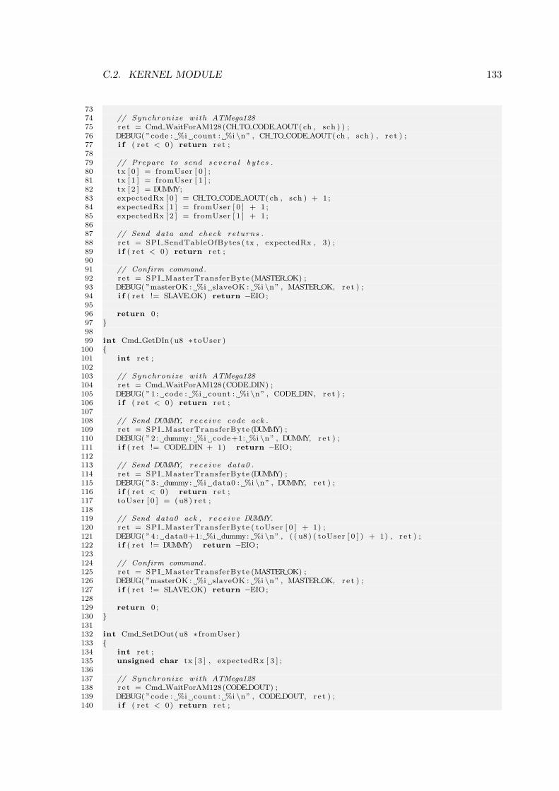
C.2. KERNEL MODULE 133
7374 // Synchronize with ATMega12875 r e t = Cmd WaitForAM128(CH TO CODE AOUT( ch , sch ) ) ;76 DEBUG( ”code : %i count : %i \n” , CH TO CODE AOUT( ch , sch ) , r e t ) ;77 i f ( r e t < 0) return r e t ;7879 // Prepare to send s e v e r a l b y t e s .80 tx [ 0 ] = fromUser [ 0 ] ;81 tx [ 1 ] = fromUser [ 1 ] ;82 tx [ 2 ] = DUMMY;83 expectedRx [ 0 ] = CH TO CODE AOUT( ch , sch ) + 1 ;84 expectedRx [ 1 ] = fromUser [ 0 ] + 1 ;85 expectedRx [ 2 ] = fromUser [ 1 ] + 1 ;8687 // Send data and check re turns .88 r e t = SPI SendTableOfBytes ( tx , expectedRx , 3) ;89 i f ( r e t < 0) return r e t ;9091 // Confirm command .92 r e t = SPI MasterTransferByte (MASTER OK) ;93 DEBUG( ”masterOK : %i slaveOK : %i \n” , MASTER OK, r e t ) ;94 i f ( r e t != SLAVE OK) return −EIO ;9596 return 0 ;97 9899 int Cmd GetDIn( u8 ∗ toUser )
100 101 int r e t ;102103 // Synchronize with ATMega128104 r e t = Cmd WaitForAM128(CODE DIN) ;105 DEBUG( ”1 : code : %i count : %i \n” , CODE DIN, r e t ) ;106 i f ( r e t < 0) return r e t ;107108 // Send DUMMY, re c e i v e code ack .109 r e t = SPI MasterTransferByte (DUMMY) ;110 DEBUG( ”2 : dummy: %i code+1: %i \n” , DUMMY, r e t ) ;111 i f ( r e t != CODE DIN + 1) return −EIO ;112113 // Send DUMMY, re c e i v e data0 .114 r e t = SPI MasterTransferByte (DUMMY) ;115 DEBUG( ”3 : dummy: %i data0 : %i \n” , DUMMY, r e t ) ;116 i f ( r e t < 0) return r e t ;117 toUser [ 0 ] = (u8 ) r e t ;118119 // Send data0 ack , r e c e i v e DUMMY.120 r e t = SPI MasterTransferByte ( toUser [ 0 ] + 1) ;121 DEBUG( ”4 : data0+1: %i dummy: %i \n” , ( ( u8 ) ( toUser [ 0 ] ) + 1) , r e t ) ;122 i f ( r e t != DUMMY) return −EIO ;123124 // Confirm command .125 r e t = SPI MasterTransferByte (MASTER OK) ;126 DEBUG( ”masterOK : %i slaveOK : %i \n” , MASTER OK, r e t ) ;127 i f ( r e t != SLAVE OK) return −EIO ;128129 return 0 ;130 131132 int Cmd SetDOut( u8 ∗ fromUser )133 134 int r e t ;135 unsigned char tx [ 3 ] , expectedRx [ 3 ] ;136137 // Synchronize with ATMega128138 r e t = Cmd WaitForAM128(CODE DOUT) ;139 DEBUG( ”code : %i count : %i \n” , CODE DOUT, r e t ) ;140 i f ( r e t < 0) return r e t ;
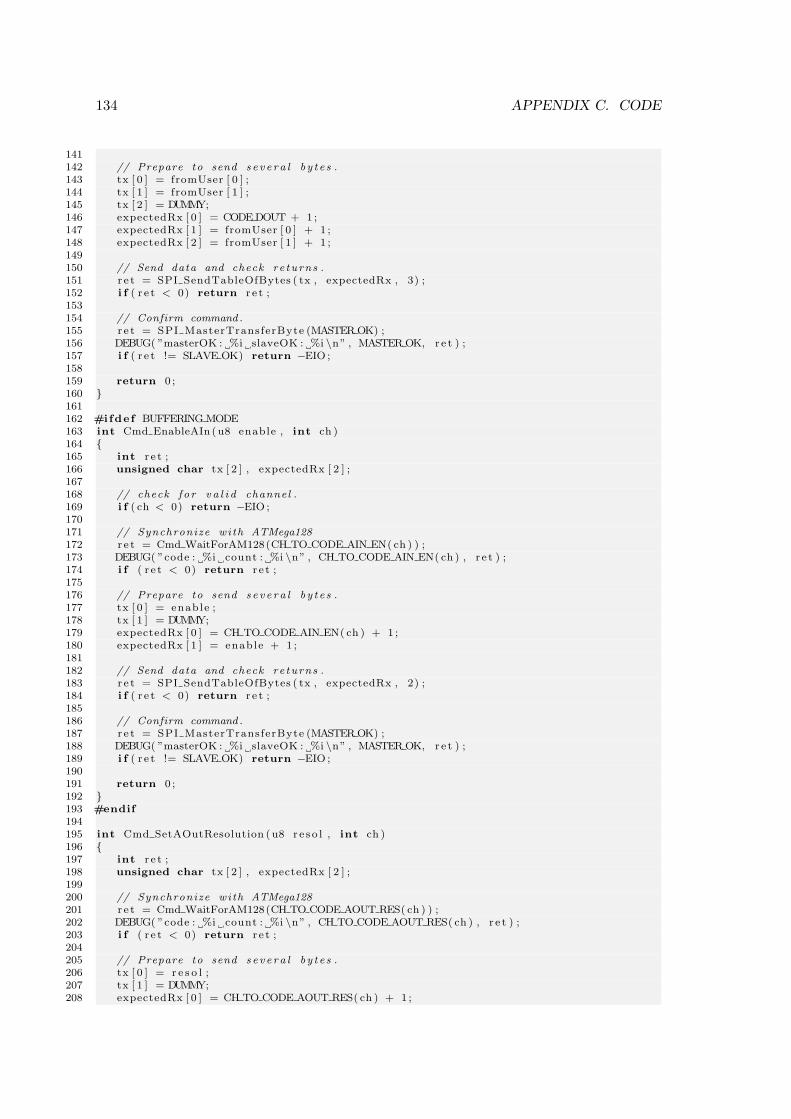
134 APPENDIX C. CODE
141142 // Prepare to send s e v e r a l b y t e s .143 tx [ 0 ] = fromUser [ 0 ] ;144 tx [ 1 ] = fromUser [ 1 ] ;145 tx [ 2 ] = DUMMY;146 expectedRx [ 0 ] = CODE DOUT + 1 ;147 expectedRx [ 1 ] = fromUser [ 0 ] + 1 ;148 expectedRx [ 2 ] = fromUser [ 1 ] + 1 ;149150 // Send data and check re turns .151 r e t = SPI SendTableOfBytes ( tx , expectedRx , 3) ;152 i f ( r e t < 0) return r e t ;153154 // Confirm command .155 r e t = SPI MasterTransferByte (MASTER OK) ;156 DEBUG( ”masterOK : %i slaveOK : %i \n” , MASTER OK, r e t ) ;157 i f ( r e t != SLAVE OK) return −EIO ;158159 return 0 ;160 161162 #ifdef BUFFERING MODE163 int Cmd EnableAIn ( u8 enable , int ch )164 165 int r e t ;166 unsigned char tx [ 2 ] , expectedRx [ 2 ] ;167168 // check f o r v a l i d channel .169 i f ( ch < 0) return −EIO ;170171 // Synchronize with ATMega128172 r e t = Cmd WaitForAM128(CH TO CODE AIN EN( ch ) ) ;173 DEBUG( ”code : %i count : %i \n” , CH TO CODE AIN EN( ch ) , r e t ) ;174 i f ( r e t < 0) return r e t ;175176 // Prepare to send s e v e r a l b y t e s .177 tx [ 0 ] = enable ;178 tx [ 1 ] = DUMMY;179 expectedRx [ 0 ] = CH TO CODE AIN EN( ch ) + 1 ;180 expectedRx [ 1 ] = enable + 1 ;181182 // Send data and check re turns .183 r e t = SPI SendTableOfBytes ( tx , expectedRx , 2) ;184 i f ( r e t < 0) return r e t ;185186 // Confirm command .187 r e t = SPI MasterTransferByte (MASTER OK) ;188 DEBUG( ”masterOK : %i slaveOK : %i \n” , MASTER OK, r e t ) ;189 i f ( r e t != SLAVE OK) return −EIO ;190191 return 0 ;192 193 #endif194195 int Cmd SetAOutResolution ( u8 r e s o l , int ch )196 197 int r e t ;198 unsigned char tx [ 2 ] , expectedRx [ 2 ] ;199200 // Synchronize with ATMega128201 r e t = Cmd WaitForAM128(CH TO CODE AOUT RES( ch ) ) ;202 DEBUG( ”code : %i count : %i \n” , CH TO CODE AOUT RES( ch ) , r e t ) ;203 i f ( r e t < 0) return r e t ;204205 // Prepare to send s e v e r a l b y t e s .206 tx [ 0 ] = r e s o l ;207 tx [ 1 ] = DUMMY;208 expectedRx [ 0 ] = CH TO CODE AOUT RES( ch ) + 1 ;
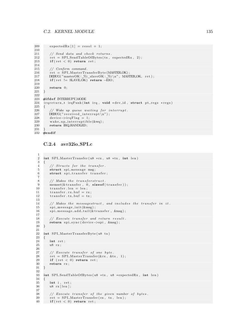
C.2. KERNEL MODULE 135
209 expectedRx [ 1 ] = r e s o l + 1 ;210211 // Send data and check re turns .212 r e t = SPI SendTableOfBytes ( tx , expectedRx , 2) ;213 i f ( r e t < 0) return r e t ;214215 // Confirm command .216 r e t = SPI MasterTransferByte (MASTER OK) ;217 DEBUG( ”masterOK : %i slaveOK : %i \n” , MASTER OK, r e t ) ;218 i f ( r e t != SLAVE OK) return −EIO ;219220 return 0 ;221 222223 #ifdef INTERRUPT MODE224 i r q r e t u r n t irqFunk ( int i rq , void ∗dev id , struct p t r e g s ∗ r eg s )225 226 // Wake up queue wai t ing f o r i n t e r r up t .227 DEBUG( ”r e c e i v ed i n t e r r up t \n”) ;228 device−>i r qF lag = 1 ;229 wake up in t e r rup t ib l e (&wq) ;230 return IRQ HANDLED;231 232 #endif
C.2.4 avr32io SPI.c
12 int SPI MasterTransfer ( u8 ∗ rx , u8 ∗ tx , int l en )3 4 // S t ruc t s f o r the t r an s f e r .5 struct sp i message msg ;6 struct s p i t r a n s f e r t r a n s f e r ;78 // Makes the t r a n s f e r s t r u c t .9 memset(& t r an s f e r , 0 , s izeof ( t r a n s f e r ) ) ;
10 t r a n s f e r . l en = len ;11 t r a n s f e r . rx bu f = rx ;12 t r a n s f e r . tx bu f = tx ;1314 // Makes the messagestruct , and inc l ude s the t r an s f e r in i t .15 s p i me s s a g e i n i t (&msg) ;16 sp i me s s a g e add t a i l (& t r an s f e r , &msg) ;1718 // Execute t r an s f e r and return r e s u l t .19 return sp i s ync ( device−>sp i , &msg) ;20 2122 int SPI MasterTransferByte ( u8 tx )23 24 int r e t ;25 u8 rx ;2627 // Execute t r an s f e r o f one by te .28 r e t = SPI MasterTransfer (&rx , &tx , 1) ;29 i f ( r e t < 0) return r e t ;30 return rx ;31 3233 int SPI SendTableOfBytes ( u8 ∗ tx , u8 ∗expectedRx , int l en )34 35 int i , r e t ;36 u8 rx [ l en ] ;3738 // Execute t r an s f e r o f the g iven number o f by t e s .39 r e t = SPI MasterTransfer ( rx , tx , l en ) ;40 i f ( r e t < 0) return r e t ;
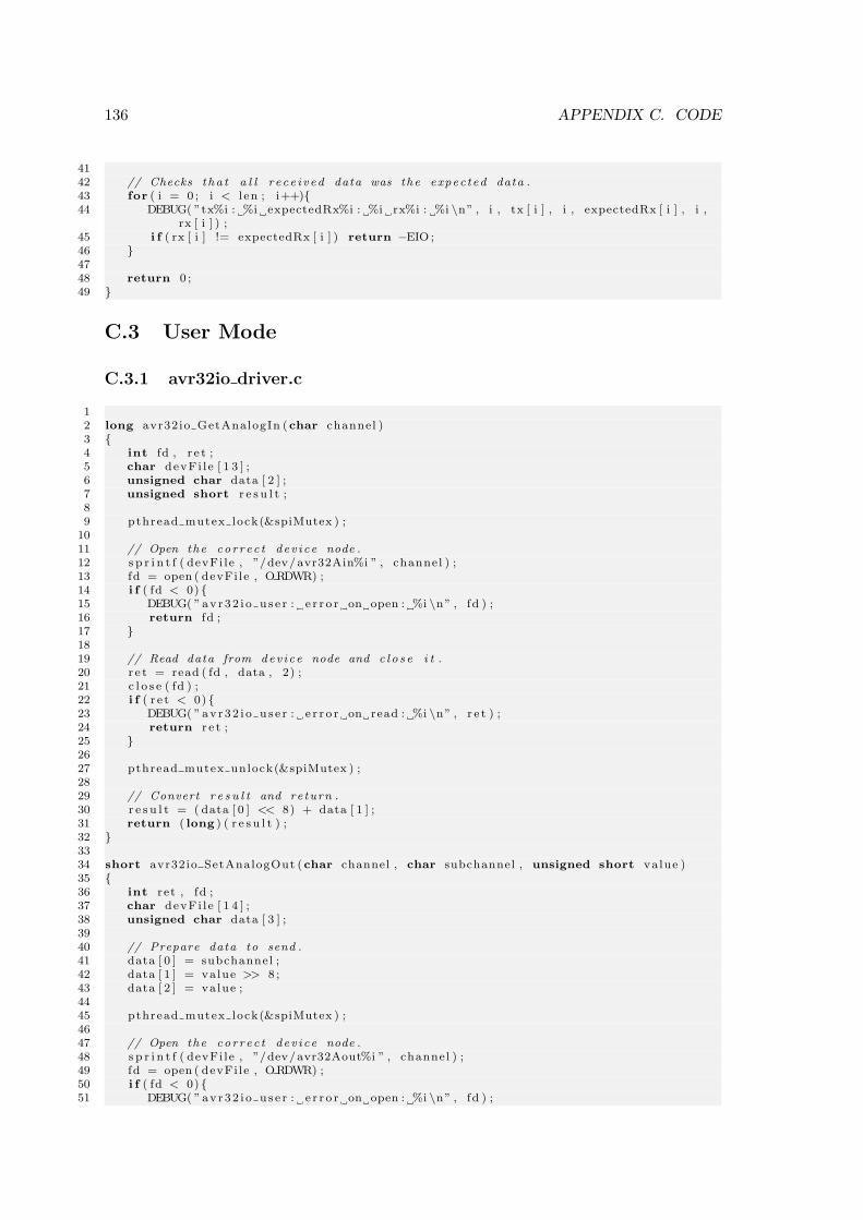
136 APPENDIX C. CODE
4142 // Checks t ha t a l l r e ce i v ed data was the expec ted data .43 for ( i = 0 ; i < l en ; i++)44 DEBUG( ”tx%i : %i expectedRx%i : %i rx%i : %i \n” , i , tx [ i ] , i , expectedRx [ i ] , i ,
rx [ i ] ) ;45 i f ( rx [ i ] != expectedRx [ i ] ) return −EIO ;46 4748 return 0 ;49
C.3 User Mode
C.3.1 avr32io driver.c
12 long avr32io GetAnalogIn (char channel )3 4 int fd , r e t ;5 char devFi l e [ 1 3 ] ;6 unsigned char data [ 2 ] ;7 unsigned short r e s u l t ;89 pthread mutex lock(&spiMutex ) ;
1011 // Open the cor r ec t dev i ce node .12 s p r i n t f ( devFi le , ”/dev/avr32Ain%i ” , channel ) ;13 fd = open ( devFi le , ORDWR) ;14 i f ( fd < 0) 15 DEBUG( ”av r32 i o u s e r : e r r o r on open : %i \n” , fd ) ;16 return fd ;17 1819 // Read data from dev i ce node and c l o s e i t .20 r e t = read ( fd , data , 2) ;21 c l o s e ( fd ) ;22 i f ( r e t < 0) 23 DEBUG( ”av r32 i o u s e r : e r r o r on read : %i \n” , r e t ) ;24 return r e t ;25 2627 pthread mutex unlock(&spiMutex ) ;2829 // Convert r e s u l t and return .30 r e s u l t = ( data [ 0 ] << 8) + data [ 1 ] ;31 return ( long ) ( r e s u l t ) ;32 3334 short avr32io SetAnalogOut (char channel , char subchannel , unsigned short value )35 36 int ret , fd ;37 char devFi l e [ 1 4 ] ;38 unsigned char data [ 3 ] ;3940 // Prepare data to send .41 data [ 0 ] = subchannel ;42 data [ 1 ] = value >> 8 ;43 data [ 2 ] = value ;4445 pthread mutex lock(&spiMutex ) ;4647 // Open the cor r ec t dev i ce node .48 s p r i n t f ( devFi le , ”/dev/avr32Aout%i ” , channel ) ;49 fd = open ( devFi le , ORDWR) ;50 i f ( fd < 0) 51 DEBUG( ”av r32 i o u s e r : e r r o r on open : %i \n” , fd ) ;
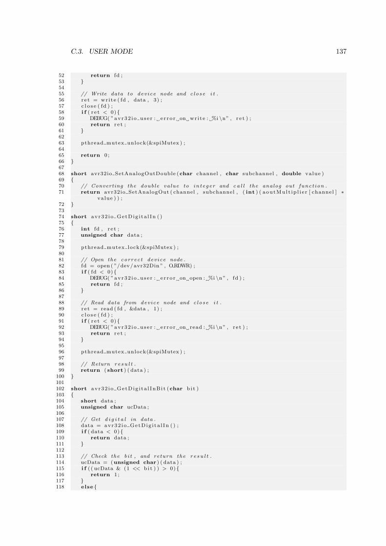
C.3. USER MODE 137
52 return fd ;53 5455 // Write data to dev i ce node and c l o s e i t .56 r e t = wr i t e ( fd , data , 3) ;57 c l o s e ( fd ) ;58 i f ( r e t < 0) 59 DEBUG( ”av r32 i o u s e r : e r r o r on wr i t e : %i \n” , r e t ) ;60 return r e t ;61 6263 pthread mutex unlock(&spiMutex ) ;6465 return 0 ;66 6768 short avr32io SetAnalogOutDouble (char channel , char subchannel , double value )69 70 // Converting the doub le va lue to i n t e g e r and c a l l the analog out func t i on .71 return avr32io SetAnalogOut ( channel , subchannel , ( int ) ( aou tMu l t i p l i e r [ channel ] ∗
value ) ) ;72 7374 short av r32 i o Ge tD ig i t a l I n ( )75 76 int fd , r e t ;77 unsigned char data ;7879 pthread mutex lock(&spiMutex ) ;8081 // Open the cor r ec t dev i ce node .82 fd = open ( ”/dev/avr32Din ” , ORDWR) ;83 i f ( fd < 0) 84 DEBUG( ”av r32 i o u s e r : e r r o r on open : %i \n” , fd ) ;85 return fd ;86 8788 // Read data from dev i ce node and c l o s e i t .89 r e t = read ( fd , &data , 1) ;90 c l o s e ( fd ) ;91 i f ( r e t < 0) 92 DEBUG( ”av r32 i o u s e r : e r r o r on read : %i \n” , r e t ) ;93 return r e t ;94 9596 pthread mutex unlock(&spiMutex ) ;9798 // Return r e s u l t .99 return ( short ) ( data ) ;
100 101102 short av r32 i o Ge tD ig i t a l I nB i t (char b i t )103 104 short data ;105 unsigned char ucData ;106107 // Get d i g i t a l in data .108 data = avr32 i o Ge tD ig i t a l I n ( ) ;109 i f ( data < 0) 110 return data ;111 112113 // Check the b i t , and return the r e s u l t .114 ucData = (unsigned char ) ( data ) ;115 i f ( ( ucData & (1 << b i t ) ) > 0) 116 return 1 ;117 118 else
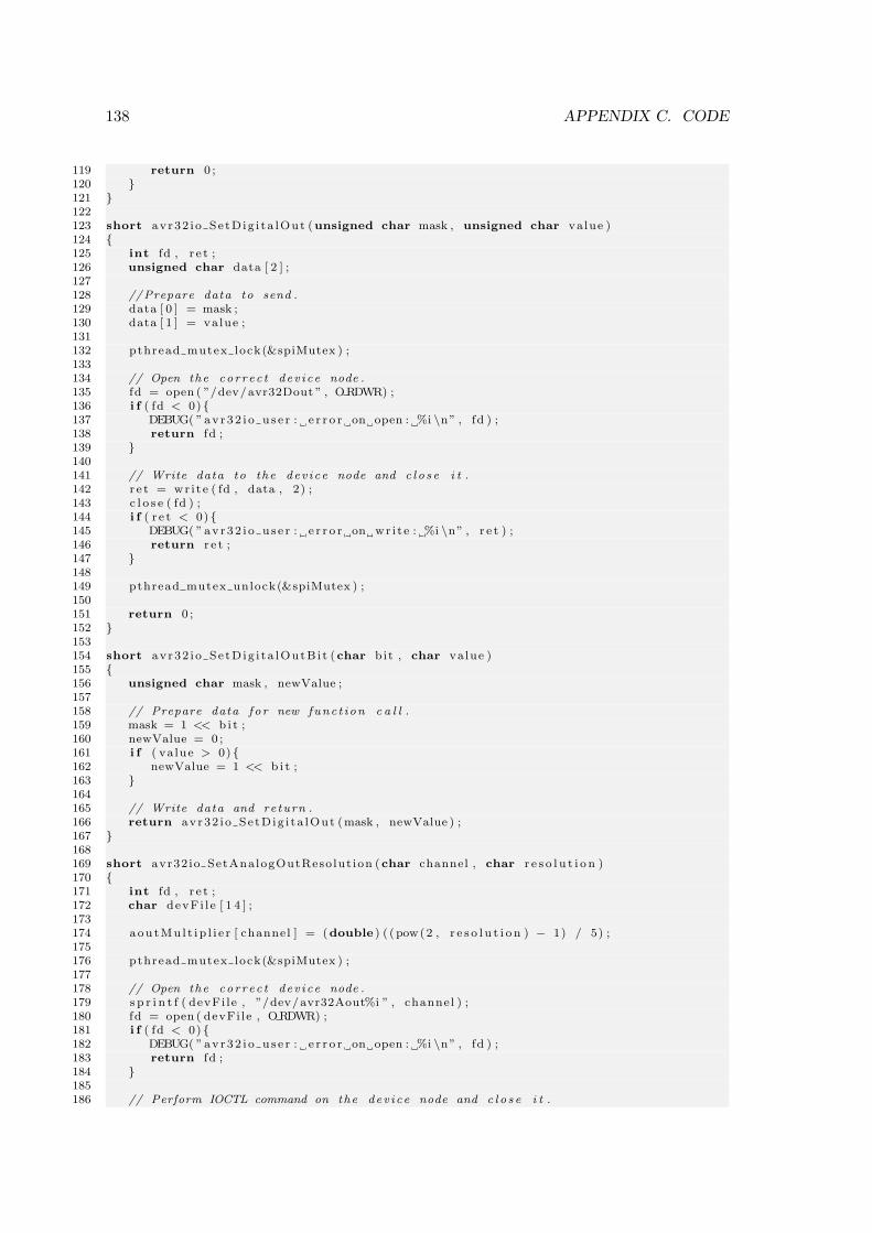
138 APPENDIX C. CODE
119 return 0 ;120 121 122123 short avr32 i o Se tD ig i t a lOut (unsigned char mask , unsigned char value )124 125 int fd , r e t ;126 unsigned char data [ 2 ] ;127128 //Prepare data to send .129 data [ 0 ] = mask ;130 data [ 1 ] = value ;131132 pthread mutex lock(&spiMutex ) ;133134 // Open the cor r ec t dev i ce node .135 fd = open ( ”/dev/avr32Dout ” , ORDWR) ;136 i f ( fd < 0) 137 DEBUG( ”av r32 i o u s e r : e r r o r on open : %i \n” , fd ) ;138 return fd ;139 140141 // Write data to the dev i ce node and c l o s e i t .142 r e t = wr i t e ( fd , data , 2) ;143 c l o s e ( fd ) ;144 i f ( r e t < 0) 145 DEBUG( ”av r32 i o u s e r : e r r o r on wr i t e : %i \n” , r e t ) ;146 return r e t ;147 148149 pthread mutex unlock(&spiMutex ) ;150151 return 0 ;152 153154 short avr32 i o Se tD ig i t a lOutB i t (char bit , char value )155 156 unsigned char mask , newValue ;157158 // Prepare data f o r new func t ion c a l l .159 mask = 1 << b i t ;160 newValue = 0 ;161 i f ( va lue > 0) 162 newValue = 1 << b i t ;163 164165 // Write data and return .166 return avr32 i o Se tD ig i t a lOut (mask , newValue ) ;167 168169 short avr32 io SetAnalogOutReso lut ion (char channel , char r e s o l u t i o n )170 171 int fd , r e t ;172 char devFi l e [ 1 4 ] ;173174 aou tMu l t i p l i e r [ channel ] = (double ) ( ( pow(2 , r e s o l u t i o n ) − 1) / 5) ;175176 pthread mutex lock(&spiMutex ) ;177178 // Open the cor r ec t dev i ce node .179 s p r i n t f ( devFi le , ”/dev/avr32Aout%i ” , channel ) ;180 fd = open ( devFi le , ORDWR) ;181 i f ( fd < 0) 182 DEBUG( ”av r32 i o u s e r : e r r o r on open : %i \n” , fd ) ;183 return fd ;184 185186 // Perform IOCTL command on the dev i ce node and c l o s e i t .
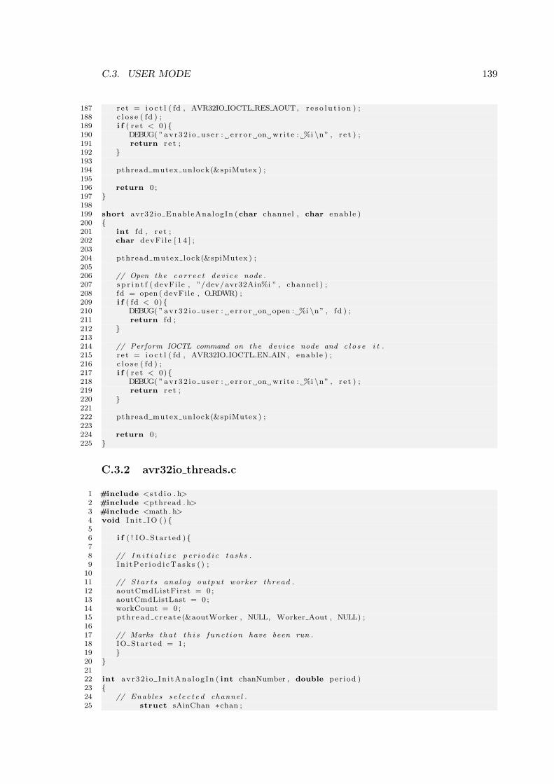
C.3. USER MODE 139
187 r e t = i o c t l ( fd , AVR32IO IOCTL RES AOUT, r e s o l u t i o n ) ;188 c l o s e ( fd ) ;189 i f ( r e t < 0) 190 DEBUG( ”av r32 i o u s e r : e r r o r on wr i t e : %i \n” , r e t ) ;191 return r e t ;192 193194 pthread mutex unlock(&spiMutex ) ;195196 return 0 ;197 198199 short avr32io EnableAnalogIn (char channel , char enable )200 201 int fd , r e t ;202 char devFi l e [ 1 4 ] ;203204 pthread mutex lock(&spiMutex ) ;205206 // Open the cor r ec t dev i ce node .207 s p r i n t f ( devFi le , ”/dev/avr32Ain%i ” , channel ) ;208 fd = open ( devFi le , ORDWR) ;209 i f ( fd < 0) 210 DEBUG( ”av r32 i o u s e r : e r r o r on open : %i \n” , fd ) ;211 return fd ;212 213214 // Perform IOCTL command on the dev i ce node and c l o s e i t .215 r e t = i o c t l ( fd , AVR32IO IOCTL EN AIN , enable ) ;216 c l o s e ( fd ) ;217 i f ( r e t < 0) 218 DEBUG( ”av r32 i o u s e r : e r r o r on wr i t e : %i \n” , r e t ) ;219 return r e t ;220 221222 pthread mutex unlock(&spiMutex ) ;223224 return 0 ;225
C.3.2 avr32io threads.c
1 #include <s t d i o . h>2 #include <pthread . h>3 #include <math . h>4 void I n i t IO ( ) 56 i f ( ! IO Started ) 78 // I n i t i a l i z e p e r i od i c t a s k s .9 In i tPe r i od i cTa sk s ( ) ;
1011 // S ta r t s analog output worker thread .12 aoutCmdListFirst = 0 ;13 aoutCmdListLast = 0 ;14 workCount = 0 ;15 pth r ead c r ea t e (&aoutWorker , NULL, Worker Aout , NULL) ;1617 // Marks t ha t t h i s func t i on have been run .18 IO Started = 1 ;19 20 2122 int avr32 i o In i tAna log In ( int chanNumber , double per iod )23 24 // Enables s e l e c t e d channel .25 struct sAinChan ∗chan ;
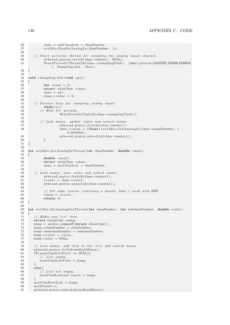
140 APPENDIX C. CODE
26 chan = ainChanList + chanNumber ;27 avr32io EnableAnalogIn ( chanNumber , 1) ;2829 // S tar t p e r i od i c thread fo r sampling the analog input channel .30 pthread mutex in i t (&(chan−>mutex ) , NULL) ;31 StartPer iod icThread (&(chan−>samplingTask ) , ( int ) ( per iod /MASTER TIMER PERIOD
) , Sampling Ain , chan ) ;32 3334 void ∗Sampling Ain (void ∗ptr )35 36 int count = 0 ;37 struct sAinChan ∗chan ;38 chan = ptr ;39 chan−>value = 0 ;4041 // Forever loop fo r sampling analog input .42 while (1 ) 43 // Wait f o r per iode .44 WaitPeriodicTask (&(chan−>samplingTask ) ) ;4546 // Lock mutex , update va lue and unlock mutex .47 pthread mutex lock (&(chan−>mutex ) ) ;48 chan−>value = ( f loat ) ( avr32io GetAnalogIn ( chan−>chanNumber ) ∗
0 .004888) ;49 pthread mutex unlock (&(chan−>mutex ) ) ;50 51 5253 int avr32io GetAnalogInThread ( int chanNumber , double ∗data )54 55 double r e s u l t ;56 struct sAinChan ∗chan ;57 chan = ainChanList + chanNumber ;5859 // Lock mutex , save va lue and unlock mutex .60 pthread mutex lock (&(chan−>mutex ) ) ;61 r e s u l t = chan−>value ;62 pthread mutex unlock (&(chan−>mutex ) ) ;6364 // For some reason re turn ing a doub le didn ’ t work with RTW65 ∗data = r e s u l t ;66 return 0 ;67 6869 int avr32io SetAnalogOutThread ( int chanNumber , int subchanNumber , double value )70 71 // Makes new l i s t item .72 struct sAoutCmd ∗temp ;73 temp = malloc ( s izeof ( struct sAoutCmd) ) ;74 temp−>chanNumber = chanNumber ;75 temp−>subchanNumber = subchanNumber ;76 temp−>value = value ;77 temp−>next = NULL;7879 // Lock mutex , add item to the l i s t and unlock mutex .80 pthread mutex lock(&cmdListMutex ) ;81 i f ( aoutCmdListFirst == NULL) 82 // L i s t empty .83 aoutCmdListFirst = temp ;84 85 else 86 // L i s t not empty .87 aoutCmdListLast−>next = temp ;88 89 aoutCmdListLast = temp ;90 workCount++;91 pthread mutex unlock(&cmdListMutex ) ;
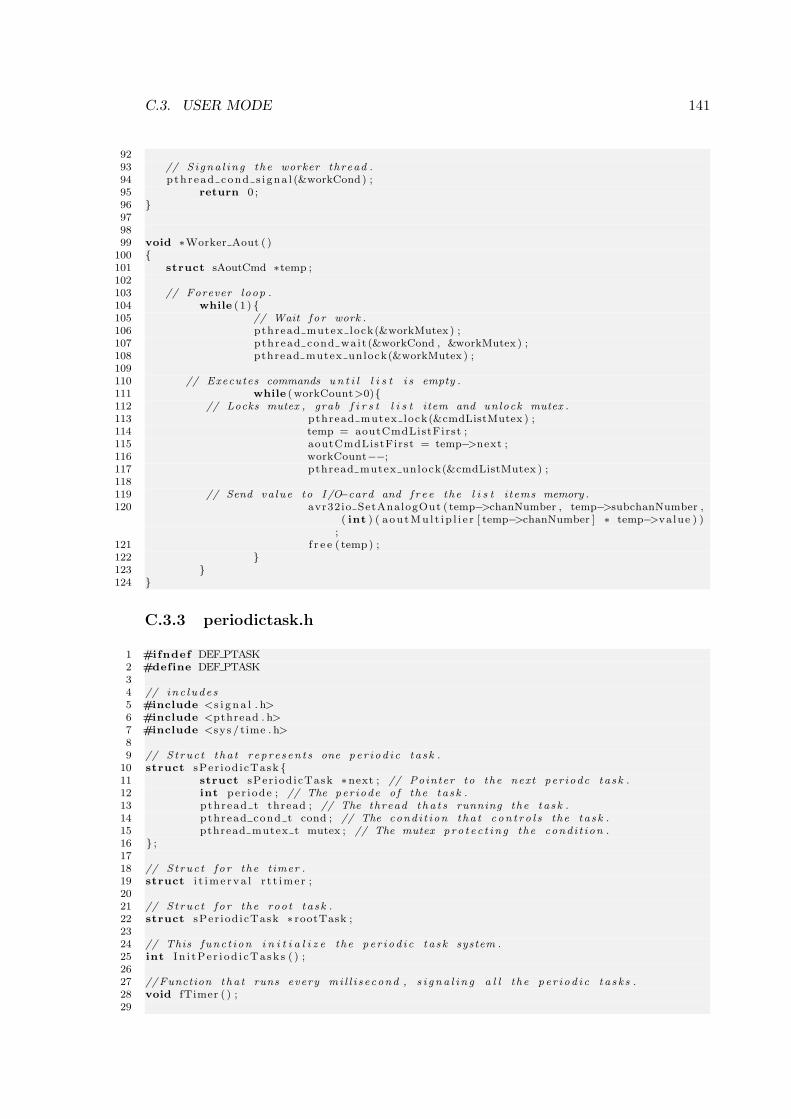
C.3. USER MODE 141
9293 // S i gna l i ng the worker thread .94 pth r ead cond s i gna l (&workCond ) ;95 return 0 ;96 979899 void ∗Worker Aout ( )
100 101 struct sAoutCmd ∗temp ;102103 // Forever loop .104 while (1 ) 105 // Wait f o r work .106 pthread mutex lock(&workMutex ) ;107 pthread cond wait (&workCond , &workMutex ) ;108 pthread mutex unlock(&workMutex ) ;109110 // Executes commands u n t i l l i s t i s empty .111 while (workCount>0)112 // Locks mutex , grab f i r s t l i s t item and unlock mutex .113 pthread mutex lock(&cmdListMutex ) ;114 temp = aoutCmdListFirst ;115 aoutCmdListFirst = temp−>next ;116 workCount−−;117 pthread mutex unlock(&cmdListMutex ) ;118119 // Send va lue to I /O−card and f r e e the l i s t i tems memory .120 avr32io SetAnalogOut ( temp−>chanNumber , temp−>subchanNumber ,
( int ) ( aou tMu l t i p l i e r [ temp−>chanNumber ] ∗ temp−>value ) );
121 f r e e ( temp) ;122 123 124
C.3.3 periodictask.h
1 #ifndef DEF PTASK2 #define DEF PTASK34 // inc l ude s5 #include <s i g n a l . h>6 #include <pthread . h>7 #include <sys / time . h>89 // S t ruc t t ha t r ep re s en t s one pe r i od i c ta sk .
10 struct sPer iod icTask 11 struct sPer iod icTask ∗next ; // Pointer to the next per iodc ta sk .12 int per iode ; // The per iode o f the ta sk .13 pthread t thread ; // The thread t ha t s running the ta sk .14 pthread cond t cond ; // The cond i t i on tha t c on t r o l s the ta sk .15 pthread mutex t mutex ; // The mutex p ro t e c t i n g the cond i t i on .16 ;1718 // S t ruc t f o r the t imer .19 struct i t ime r va l r t t ime r ;2021 // S t ruc t f o r the root ta sk .22 struct sPer iod icTask ∗ rootTask ;2324 // This func t i on i n i t i a l i z e the pe r i od i c ta sk system .25 int I n i tPe r i od i cTa sk s ( ) ;2627 //Function tha t runs every mi l l i s econd , s i g n a l i n g a l l the pe r i od i c t a s k s .28 void fTimer ( ) ;29
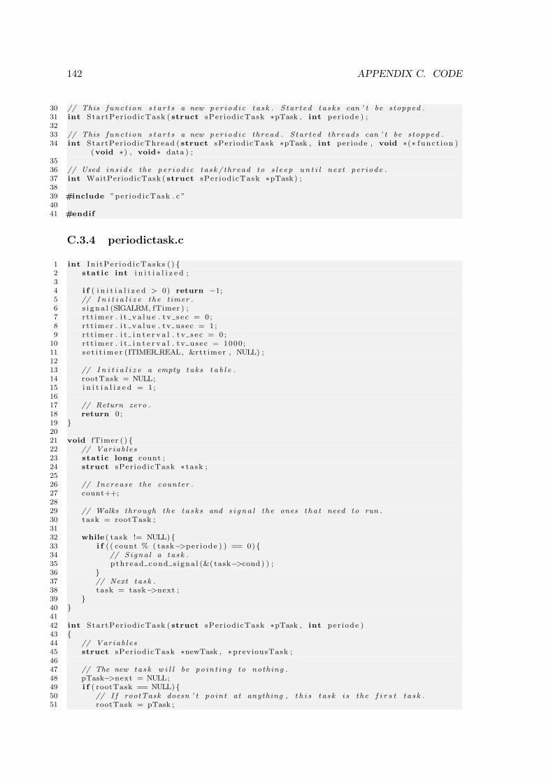
142 APPENDIX C. CODE
30 // This func t i on s t a r t s a new pe r i od i c ta sk . S tar t ed t a s k s can ’ t be s topped .31 int Star tPer iod i cTask ( struct sPer iod icTask ∗pTask , int per iode ) ;3233 // This func t i on s t a r t s a new pe r i od i c thread . S tar t ed threads can ’ t be s topped .34 int StartPer iod icThread ( struct sPer iod icTask ∗pTask , int per iode , void ∗(∗ f unc t i on )
(void ∗) , void∗ data ) ;3536 // Used in s i d e the pe r i od i c ta sk / thread to s l e e p u n t i l next per iode .37 int WaitPeriodicTask ( struct sPer iod icTask ∗pTask ) ;3839 #include ”per iod icTask . c ”4041 #endif
C.3.4 periodictask.c
1 int I n i tPe r i od i cTa sk s ( ) 2 stat ic int i n i t i a l i z e d ;34 i f ( i n i t i a l i z e d > 0) return −1;5 // I n i t i a l i z e the t imer .6 s i g n a l (SIGALRM, fTimer ) ;7 r t t ime r . i t v a l u e . t v s e c = 0 ;8 r t t ime r . i t v a l u e . tv usec = 1 ;9 r t t ime r . i t i n t e r v a l . t v s e c = 0 ;
10 r t t ime r . i t i n t e r v a l . t v usec = 1000 ;11 s e t i t im e r (ITIMER REAL, &rtt imer , NULL) ;1213 // I n i t i a l i z e a empty tak s t a b l e .14 rootTask = NULL;15 i n i t i a l i z e d = 1 ;1617 // Return zero .18 return 0 ;19 2021 void fTimer ( ) 22 // Var iab l e s23 stat ic long count ;24 struct sPer iod icTask ∗ task ;2526 // Increase the counter .27 count++;2829 // Walks through the t a s k s and s i g n a l the ones t ha t need to run .30 task = rootTask ;3132 while ( task != NULL) 33 i f ( ( count % ( task−>per iode ) ) == 0) 34 // S igna l a ta sk .35 pth r ead cond s i gna l (&( task−>cond ) ) ;36 37 // Next ta sk .38 task = task−>next ;39 40 4142 int Star tPer iod i cTask ( struct sPer iod icTask ∗pTask , int per iode )43 44 // Var iab l e s45 struct sPer iod icTask ∗newTask , ∗previousTask ;4647 // The new task w i l l be po in t ing to nothing .48 pTask−>next = NULL;49 i f ( rootTask == NULL) 50 // I f rootTask doesn ’ t po in t at anything , t h i s t a sk i s the f i r s t t a s k .51 rootTask = pTask ;
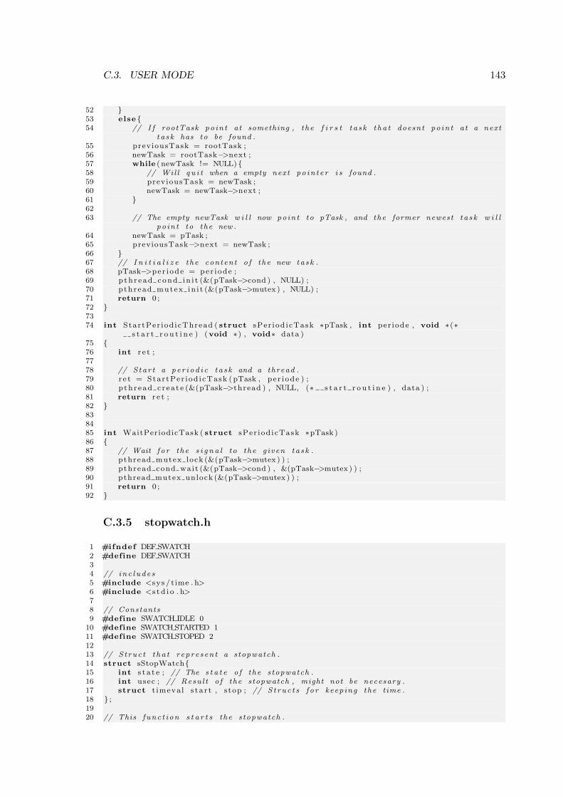
C.3. USER MODE 143
52 53 else 54 // I f rootTask po in t at something , the f i r s t t a s k t ha t doesnt po in t at a next
t a sk has to be found .55 previousTask = rootTask ;56 newTask = rootTask−>next ;57 while ( newTask != NULL) 58 // Wil l q u i t when a empty next po in t e r i s found .59 previousTask = newTask ;60 newTask = newTask−>next ;61 6263 // The empty newTask w i l l now poin t to pTask , and the former newest t a sk w i l l
po in t to the new .64 newTask = pTask ;65 previousTask−>next = newTask ;66 67 // I n i t i a l i z e the content o f the new task .68 pTask−>per iode = per iode ;69 p th r ead cond in i t (&(pTask−>cond ) , NULL) ;70 pthread mutex in i t (&(pTask−>mutex ) , NULL) ;71 return 0 ;72 7374 int StartPer iod icThread ( struct sPer iod icTask ∗pTask , int per iode , void ∗(∗
s t a r t r o u t i n e ) (void ∗) , void∗ data )75 76 int r e t ;7778 // S tar t a pe r i od i c ta sk and a thread .79 r e t = Star tPer iod i cTask (pTask , pe r i ode ) ;80 pth r ead c r ea t e (&(pTask−>thread ) , NULL, (∗ s t a r t r o u t i n e ) , data ) ;81 return r e t ;82 838485 int WaitPeriodicTask ( struct sPer iod icTask ∗pTask )86 87 // Wait f o r the s i g n a l to the g iven ta sk .88 pthread mutex lock (&(pTask−>mutex ) ) ;89 pthread cond wait (&(pTask−>cond ) , &(pTask−>mutex ) ) ;90 pthread mutex unlock (&(pTask−>mutex ) ) ;91 return 0 ;92
C.3.5 stopwatch.h
1 #ifndef DEF SWATCH2 #define DEF SWATCH34 // inc l ude s5 #include <sys / time . h>6 #include <s t d i o . h>78 // Constants9 #define SWATCH IDLE 0
10 #define SWATCH STARTED 111 #define SWATCH STOPED 21213 // S t ruc t t ha t repre sen t a stopwatch .14 struct sStopWatch15 int s t a t e ; // The s t a t e o f the stopwatch .16 int usec ; // Resu l t o f the stopwatch , might not be necesary .17 struct t imeva l s ta r t , stop ; // S t ruc t s f o r keeping the time .18 ;1920 // This func t i on s t a r t s the stopwatch .
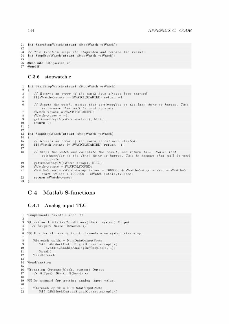
144 APPENDIX C. CODE
21 int StartStopWatch ( struct sStopWatch ∗sWatch ) ;2223 // This func t i on s tops the stopwatch and re turns the r e s u l t .24 int StopStopWatch ( struct sStopWatch ∗sWatch ) ;2526 #include ”stopwatch . c ”27 #endif
C.3.6 stopwatch.c
1 int StartStopWatch ( struct sStopWatch ∗sWatch )2 3 // Returns an error i f the watch have a l ready been s t a r t e d .4 i f ( sWatch−>s t a t e == SWATCH STARTED) return −1;56 // S ta r t s the watch , no t i c e t ha t ge t t imeo fday i s the l a s t t h ing to happen . This
i s because t ha t w i l l be most accurate .7 sWatch−>s t a t e = SWATCH STARTED;8 sWatch−>usec = −1;9 gett imeofday (&(sWatch−>s t a r t ) , NULL) ;
10 return 0 ;11 1213 int StopStopWatch ( struct sStopWatch ∗sWatch )14 15 // Returns an error i f the watch havent been s t a r t e d .16 i f ( sWatch−>s t a t e != SWATCH STARTED) return −1;1718 // Stops the watch and c a l c u l a t e the r e su l t , and return t h i s . Notice t ha t
ge t t imeo fday i s the f i r s t t h ing to happen . This i s because t ha t w i l l be mostaccurate .
19 gett imeofday (&(sWatch−>stop ) , NULL) ;20 sWatch−>s t a t e = SWATCH STOPED;21 sWatch−>usec = sWatch−>stop . t v s e c ∗ 1000000 + sWatch−>stop . tv usec − sWatch−>
s t a r t . t v s e c ∗ 1000000 − sWatch−>s t a r t . tv usec ;22 return sWatch−>usec ;23
C.4 Matlab S-functions
C.4.1 Analog input TLC
1 %implements ”avr32 io adc ” ”C”23 %func t i on I n i t i a l i z eC o nd i t i o n s ( block , system ) Output4 /∗ %<Type> Block : %<Name> ∗/56 %% Enables a l l analog input channe l s when system s t a r t s up .78 %fo r each opIdx = NumDataOutputPorts9 %i f LibBlockOutputSignalConnected ( opIdx )
10 avr32io EnableAnalogIn(%<opIdx >, 1) ;11 %end i f12 %endforeach1314 %endfunct ion1516 %func t i on Outputs ( block , system ) Output17 /∗ %<Type> Block : %<Name> ∗/1819 %% Do command for g e t t i n g analog input value .2021 %fo reach opIdx = NumDataOutputPorts22 %i f LibBlockOutputSignalConnected ( opIdx )
C.4. MATLAB S-FUNCTIONS 145
23 %<LibBlockOutputSignal ( opIdx , ”” , ”” , 0)> = avr32io GetAnalogIn(%<opIdx>)∗ 0 .0048828 ;
24 %end i f25 %endforeach2627 %endfunct ion
C.4.2 Analog output TLC
1 %implements ”avr32 io dac ” ”C”234 %func t i on I n i t i a l i z eC o nd i t i o n s ( block , system ) Output5 /∗ %<Type> Block : %<Name> ∗/67 %% Set r e s o l u t i o n for both o f the analog out channe l s .89 avr32 io SetAnalogOutReso lut ion (0 , ( int )%<LibBlockParameter (P1 , ”” , ”” , 0)> + 7) ;
10 avr32 io SetAnalogOutReso lut ion (1 , ( int )%<LibBlockParameter (P2 , ”” , ”” , 0)> + 7) ;1112 %endfunct ion1314 %func t i on Outputs ( block , system ) Output15 /∗ %<Type> Block : %<Name> ∗/1617 %%Loops through a l l ports , and s e t analog out f unc t i on s for the por t s that are
connected .1819 stat ic int count [ 6 ] ;20 int r e t ;21 %fo r each opIdx = NumDataInputPorts22 %i f LibBlockInputSignalConnected ( opIdx )23 %i f opIdx<324 r e t = avr32io SetAnalogOutDouble (0 , %<opIdx >, (double )(%<
LibBlockInputS igna l ( opIdx , ”” , ”” , 0)>)) ;25 %else26 r e t = avr32io SetAnalogOutDouble (1 , %<opIdx> − 3 , (double )(%<
LibBlockInputS igna l ( opIdx , ”” , ”” , 0)>)) ;27 %end i f28 i f ( r e t < 0) 29 count[%<opIdx>]++;30 p r i n t f ( ”%<opIdx> count : %i data : %f \n” , count[%<opIdx > ] , %<
LibBlockInputS igna l ( opIdx , ”” , ”” , 0)>) ;31 32 %end i f33 %endforeach34 %endfunct ion
C.4.3 Digital input TLC
1 %implements ”av r32 i o d in ” ”C”23 %func t i on Outputs ( block , system ) Output4 /∗ %<Type> Block : %<Name> ∗/56 %% Reads d i g i t a l inout va lue s from I /O−card .78 unsigned char din = avr32 i o Ge tD ig i t a l I n ( ) ;9
10 %fo r each opIdx = NumDataOutputPorts11 %i f LibBlockOutputSignalConnected ( opIdx )12 i f ( din & (1<<%<opIdx>) ) 13 %<LibBlockOutputSignal ( opIdx , ”” , ”” , 0)> = 5 ;14 15 else 16 %<LibBlockOutputSignal ( opIdx , ”” , ”” , 0)> = 0 ;
146 APPENDIX C. CODE
17 18 %end i f19 %endforeach2021 %endfunct ion
C.4.4 Digital output TLC
1 %implements ”avr32 io dout ” ”C”23 %func t i on Outputs ( block , system ) Output4 /∗ %<Type> Block : %<Name> ∗/56 %% Checking a l l channe l s and make a mask and data byte that are sendt as a command
to the I /O−card .78 unsigned char dout = 0 ;9 unsigned char mask = 0 ;
1011 %i f LibBlockInputSignalConnected (0 )12 mask = mask | (1<<0) ;13 i f ( (double )(%<LibBlockInputS igna l (0 , ”” , ”” , 0)>) >= (double )(%<
LibBlockParameter (P1 , ”” , ”” , 0)>)) 14 dout = dout | (1<<0) ;15 16 %end i f17 %i f LibBlockInputSignalConnected (1 )18 mask = mask | (1<<1) ;19 i f ( (double )(%<LibBlockInputS igna l (1 , ”” , ”” , 0)>) >= (double )(%<
LibBlockParameter (P2 , ”” , ”” , 0)>)) 20 dout = dout | (1<<1) ;21 22 %end i f23 %i f LibBlockInputSignalConnected (2 )24 mask = mask | (1<<2) ;25 i f ( (double )(%<LibBlockInputS igna l (2 , ”” , ”” , 0)>) >= (double )(%<
LibBlockParameter (P3 , ”” , ”” , 0)>)) 26 dout = dout | (1<<2) ;27 28 %end i f29 %i f LibBlockInputSignalConnected (3 )30 mask = mask | (1<<3) ;31 i f ( (double )(%<LibBlockInputS igna l (3 , ”” , ”” , 0)>) >= (double )(%<
LibBlockParameter (P4 , ”” , ”” , 0)>)) 32 dout = dout | (1<<3) ;33 34 %end i f35 %i f LibBlockInputSignalConnected (4 )36 mask = mask | (1<<4) ;37 i f ( (double )(%<LibBlockInputS igna l (4 , ”” , ”” , 0)>) >= (double )(%<
LibBlockParameter (P5 , ”” , ”” , 0)>)) 38 dout = dout | (1<<4) ;39 40 %end i f41 %i f LibBlockInputSignalConnected (5 )42 mask = mask | (1<<5) ;43 i f ( (double )(%<LibBlockInputS igna l (5 , ”” , ”” , 0)>) >= (double )(%<
LibBlockParameter (P6 , ”” , ”” , 0)>)) 44 dout = dout | (1<<5) ;45 46 %end i f47 %i f LibBlockInputSignalConnected (6 )48 mask = mask | (1<<6) ;49 i f ( (double )(%<LibBlockInputS igna l (6 , ”” , ”” , 0)>) >= (double )(%<
LibBlockParameter (P7 , ”” , ”” , 0)>)) 50 dout = dout | (1<<6) ;51
C.4. MATLAB S-FUNCTIONS 147
52 %end i f53 %i f LibBlockInputSignalConnected (7 )54 mask = mask | (1<<7) ;55 i f ( (double )(%<LibBlockInputS igna l (7 , ”” , ”” , 0)>) >= (double )(%<
LibBlockParameter (P8 , ”” , ”” , 0)>)) 56 dout = dout | (1<<7) ;57 58 %end i f5960 avr32 i o Se tD ig i t a lOut (mask , dout ) ;6162 %endfunct ion
Bibliography
[1] ATmega128 datasheet.
[2] AVR32 32-bit MCU/DSP Overview. Atmel Corporation.http://www.atmel.com/products/AVR32.
[3] AVR32 Linux Wiki. AVR32 Linux Wiki contributors. http://www.avr32linux.org.
[4] Eagle Layout Editor. CadSoft. http://www.cadsoft.de/.
[5] MAXIM 233 datasheet.
[6] MC1458 datasheet.
[7] MC7805 datasheet.
[8] STK1000. Atmel Corporation.http://www.atmel.com/dyn/products/tools_card.asp?tool_id=3918.
[9] STK500 User guide.
[10] Ubuntu. Canonical Ltd. http://www.ubuntu.com.
[11] AVR32 Architecture Manual. Atmel Corporation, Feb 2006.
[12] Real-Time Workshop Target Language Compiler. The Mathworks, Mar 2007.
[13] Real-Time Workshop Target User’s Guide. The Mathworks, Mar 2007.
[14] Wikipedia contributors. Control System. Wikipedia, The Free Encyclopedia., May2007. http://en.wikipedia.org/w/index.php?title=Control_system&oldid=131753209.
[15] Wikipedia contributors. Linux Kernel. Wikipedia, The Free Encyclopedia., Jun2007. http://en.wikipedia.org/w/index.php?title=Linux_kernel&oldid=137027739.
[16] Wikipedia contributors. Porting. Wikipedia, The Free Encyclopedia., Jun 2007.http://en.wikipedia.org/w/index.php?title=Porting&oldid=136428272.
[17] Wikipedia contributors. Porting. Wikipedia, The Free Encyclopedia., May 2007.http://en.wikipedia.org/w/index.php?title=APT&oldid=131003365.
[18] Wikipedia contributors. Real-Time Computing. Wikipedia, The Free Encyclopedia.,Jun 2007.http://en.wikipedia.org/w/index.php?title=Real-time_computing&oldid=135997153.
[19] Wikipedia contributors. Ring. Wikipedia, The Free Encyclopedia., May 2007. http:
//en.wikipedia.org/w/index.php?title=Ring_%28computer_security%29&oldid=131608375.
148
BIBLIOGRAPHY 149
[20] Marco Cesati Daniel P. Bovet. Understanding the Linux Kernel. O’Reilly, 3rdedition, Nov 2005.
[21] Greg Kroah-Hartman Jonathan Corbet, Alessandro Rubini. Linux Device Drivers.O’Reilly, 3rd edition, February 2005.
[22] Lindergren. Apent marked for Linux Embedded. Datarespons - Interrupt, 2006.http://www.datarespons.com/templates/interrupt.aspx?id=1826.
[23] GNU Project. The Free Software Definition. GNU Project, February 2007.http://www.gnu.org/philosophy/free-sw.html.
[24] Øyvind Netland. Rapid prototyping with matlab real-time workhsop on anembedded control system with atmel avr32 processor. Master’s thesis, NTNU, 2007.


![Atmel ATSHA204 - SparkFun Electronicscdn.sparkfun.com/.../Atmel-8740-CryptoAuth-ATSHA204-Datasheet.pdf · Atmel ATSHA204 [DATASHEET] 5 Atmel–8740E–CryptoAuth–ATSHA204–Datasheet–022013](https://img.pdfslide.net/doc/110x75/5e25fe64d9a5567efa4c5ccc/atmel-atsha204-sparkfun-atmel-atsha204-datasheet-5-atmela8740eacryptoauthaatsha204adatasheeta022013.jpg)


![Atmel SAM9M10 Datasheet - Farnell element14 · SAM9M10 [DATASHEET] 5 Atmel-6355G-ATARM-SAM9M10-Datasheet_02-Sept-14 Shutdown, Wakeup Logic SHDN Shut-Down Control Output – VDDBU](https://img.pdfslide.net/doc/110x75/5e99def036a883700e2b3f6b/atmel-sam9m10-datasheet-farnell-sam9m10-datasheet-5-atmel-6355g-atarm-sam9m10-datasheet02-sept-14.jpg)