Embed Size (px)
Citation preview
DEVELOPMENT OF A MOTORIZED CUTTER (ELECTRO-MECHANICAL PART) AND INTEGRATION SYSTEM
NADIRAH BINTI ISMAIL
A report submitted in partial fulfilment of the requirementfor the award of the degree of
Diploma of Mechanical Engineering
Faculty of Mechanical EngineeringUNIVERSITI MALAYSIA PAHANG
NOVEMBER 2008
SUPERVISOR’S DECLARATION
“I hereby declare that we have checked this project and in my opinion this project is
satisfactory in terms of scope and quality for the award of the degree of Diploma of
Mechanical Engineering”
Signature:
Name of Supervisor: En Shahmi B. Junoh@yacob
Date:

STUDENT’S DECLARATION
I hereby declare that the work in this thesis is my own except for quotations and
summaries which have been duly acknowledged. The thesis has not been accepted for
any degree and is not concurently submitted for award of other degree.
Signature:
Name: Nadirah Binti Ismail
ID Number: MB06037
Date:

DEDICATION
To my beloved parents, Mr. Ismail Bin Ainuddin and Mdm. Noridah Binti
Harun, other siblings, family and friends, without whom and his/her lifetime efforts in
encouraging and supporting my pursuit of higher education in Mechanical Engineering.
Not forgotten to all staff of Faculty of Mechanical Engineering form University
Malaysia Pahang especially my supervisor, Mr. Shahmi Bin Junoh@Yacob for giving
me this opportunity and providing conducive environment in completing this project.

ACKNOWLEDGEMENT
First and foremost, I would like to express my profound gratitude to my
supervisor, Mr. Shahmi Bin Junoh@Yacob for his precious guidance and continuous
encouragements during the whole course of completing this project. All his advices and
ideas have eventually contributed to the success of this project. I am grateful and
honoured to be given the chance to have taken up this project as part of on going
research of motorized cutter.
I would also like to wish my special thanks to my course mates who have
inspired me and helped me throughout my project.
Lastly, but not least, my sincere Mr. Ismail Bin Ali for his concern of my
project progress and also other lecturers and technician who had directly and indirectly
contributed in completing this project.
ABSTRAC
A motorized cutter been designed to use in harvesting fresh fruit bunches especially
during fruit season. The main reason for the motorized cutter been designed is to make
it easier for the users or consumers operating the cutter without using high energy. The
motorized cutter had been support with 24V DC motor, 24V rechargeable battery, cable
and other electrical components. H-bridge concept being used in electrical circuit so
that the motor rotor can rotate clockwise or anti clockwise when the push button is
pressed.

ABSTRAK
Sebuah pemotong bermotor dibuat khas untuk digunakan ketika mengait buah yg sudah
masak terutama pada musim buah. Tujuan utama pemotong bermotor ini direka untuk
memudahkan para pengguna untuk mengait buah-buahan tanpa menggunakan tenaga
yang tinggi. Pemotong bermotor ini dilengkapi dengan sistem elektrik dimana
menggunakn 24V DC motor, 24V bateri caj, kabel dan juga komponen-komponen
elektrik lain yang juga turut digunakan. Konsep H-bridge digunakan dalam litar elektrik
bagi memudahkan motor berpusing mengikut lawan jam atau arah lawan jam apabila
butang suis ditekan.
TABLE OF CONTENTS
CHAPTER TITLE PAGE
TITLE PAGE I
SUPERVISOR DECLARATION II
DECLARATION III
DEDICATION IV
ACKNOWLEDGEMENT V
ABSTRACT VI
ABSTRAK VII
TABLE OF CONTENTS VIII
LIST OF TABLES XI
LIST OF FIGURES XIII
LIST OF ABBREVIATIONS XIV
1 INTRODUCTION 1
1.1 Introduction for Motorized Cutter 1
1.1.1 Introduction to DC Motor 1 1.1.2 Introduction to Battery 21.1.3 Introduction to Cable 3
1.2 Background of Project 4
1.3 Problem Statement 4
1.4 Objective 5
1.5 Scopes 5
1.6 Project Organization 5
2 LITERATURE REVIEW 7
2.1 Introduction 7
2.2 Types of Motorized Cutter 8
2.2.1 Wilkinsword Telescopic Tree Pruner 82.2.2 Telescopic Universal Cutter 82.2.3 Fiskars Pruner 9
2.3 Types of drive motor 10
2.3.1 AC Induction Motor ( Shaded pole) 10 2.3.2 AC Induction Motor 2.3.3 AC Synchronous Motor 112.3.4 Stepper DC Motor 122.3.5 Brushed DC Motor 13
2.4 Types of Sheet Metal (Motor Casing) 15
2.4.1 Copper 152.4.2 Aluminium 15
3 METHODOLOGY 18
3.1 Introduction 18
3.2 Overall Methodology 19
3.3 Gantt Chart 22
3.4 Process Involved in Project 23
3.4.1 Motor Casing 233.4.2 Process in making Motor Casing 23 3.4.3 Procedure in making Motor Casing 25 3.4.4 Electrical circuit 26
3.4.4.1 Soldering Process 26 3.4.4.2 H-bridge Concept 27
3.4.5 Process in making Electrical Circuit 27 3.4.6 Procedure in making Electrical Circuit 28
3.5 Manufacturing Process Involve 28
3.5.1 Metal Inert Gas (MIG) Welding 283.5.2 Drilling Machine 293.5.3 Vertical Bendsaw 30
3.6 Process Picture 30
4 RESULT AND DISCUSSION 31
4.1 Aspect in Design 33
4.1.1 Motor Casing 33 4.1.2 Electrical Circuit 33
4.2 Drawing 34
4.3 Specification for Motor 34
4.4 Specification for Aluminium (Motor Casing) 34
4.5 Sketching Drawing 35
4.5.1 Motor Casing 35 4.5.2 Electrical Circuit 35
4.6 Finalized Design 36
4.6.1 Solidwork Drawing 364.6.2 DXP Protel 37
4.7 The Whole Product Preview (Pictue) 37
4.8 Testing of the Product (Picture) 38
4.9 Results 38
4.10 Discussion for the Results 39
5 CONCLUSION AND RECOMMENDATION 40
5.1 Introduction 40
5.2 Project Problems 40
5.3 Conclusion 41
5.4 Recommendations 42
REFERENCES 42
APPENDICES 43 - 45

LIST OF FIGURES
FIGURE NO. TITLE PAGE
2.1 Wilkinsword Telescopic Universal Cutter 8
2.2 Telescopic Tree Pruner 8
2.3 Fiskars Pruner 9
2.4 AC Induction Motor (Shaded pole) 10
2.5 AC Induction Motor 11
2.6 AC Synchronous Motor 12
2.7 Stepper DC Motor 13
2.8 Brushed DC Motor 14
3.1 Overall Methodology 20
3.2 Process Involved in making Motor Casing 25
3.3 Soldering Components 26
3.4 H-bridge Concept 27
3.5 Procedure in making Electrical Circuit 28
3.6 Measuring Process 30
3.7 Cutting Process 30
3.8 Bending Process 31
3.9 Grinding Process 31
3.10 Welding Process 31
3.11 Drilling Process 32
3.12 Spraying Process 32
4.1 Sketching (Motor Casing) 35
4.2 Sketching (Electrical circuit) 35
4.3 Solidwork for Motor Casing 36
4.4 Solidwork for motor casing with motor inside it 36
4.5 DXP Protel Circuit 37
4.6 The Whole Product Preview 37
4.7 Testing of the Motorized Cutter (picture) 38
LIST OF TABLES
TABLE NO. TITLE PAGE
2.1 Comparisons Types of Motor 14
2.2 Comparisons Types of Sheet Metal 17
3.1 Gantt Chart 22
LIST OF ABBREVIATION
MIG Metal Inert Gas
DC Direct Current
AC Alternating Current
LED Light Emitting Diode
CHAPTER 1
INTRODUCTION
1.1 INTRODUCTION FOR MOTORIZED CUTTER
A cutter for harvesting fresh fruit bunches and pruning fronds is easier to find in
the current market nowadays. It has been used for a long time ago especially during
fruit season such as rambutan season. Therefore with our modern technology, a new
motorized cutter have been created so that make it easier to the farmer in collecting
fruit bunches and pruning fronds. A motorized cutter was driven by (DC) motor when
operating it. The other component uses in motorized cutter are battery, LED, resistor,
cable and aluminium plate ( motor casing).
1.1.1 INTRODUCTION TO DC MOTOR
A DC motor is an electric motor that runs on direct current (DC) electricity. A
DC motor works by converting electric power into mechanical work. This is
accomplished by forcing current through a coil and producing a magnetic field that
spins the motor. The simplest DC motor is a single coil apparatus, used here to discuss
the DC motor theory.
The voltage source forces voltage through the coil via sliding contacts or brushes
that are connected to the DC source. These brushes are found on the end of the coil
wires and make a temporary electrical connection with the voltage source. In this
motor, the brushes will make a connection every 180 degrees and current will then flow
through the coil wires. At 0 degrees, the brushes are in contact with the voltage source
and current is flowing. The current that flows through wire segment C-D interacts with
the magnetic field that is present and the result is an upward force on the segment.
The current that flows through segment A-B has the same interaction, but the
force is in the downward direction. Both forces are of equal magnitude, but in opposing
directions since the direction of current flow in the segments is reversed with respect to
the magnetic field. At 180 degrees, the same phenomenon occurs, but segment A-B is
forced up and C-D is forced down. At 90 and 270-degrees, the brushes are not in
contact with the voltage source and no force is produced. In these two positions, the
rotational kinetic energy of the motor keeps it spinning until the brushes regain contact.
The brushed DC motor generates torque directly from DC power supplied to the
motor by using internal commutation, stationary permanent magnets, and rotating
electrical magnets. Advantages of a brushed DC motor include low initial cost, high
reliability, and simple control of motor speed. Disadvantages are high maintenance and
low life-span for high intensity uses. Maintenance involves regularly replacing the
brushes and springs which carry the electric current, as well as cleaning or replacing the
commutator. These components are necessary for transferring electrical power from
outside the motor to the spinning wire windings of the rotor inside the motor
Brushless DC motors use a rotating permanent magnet in the rotor, and stationary
electrical magnets on the motor housing. A motor controller converts DC to AC. This
design is simpler than that of brushed motors because it eliminates the complication of
transferring power from outside the motor to the spinning rotor. Advantages of
brushless motors include long life span, little or no maintenance, and high efficiency.
Disadvantages include high initial cost, and more complicated motor speed controllers.
1.1.2 INTRODUCTION TO BATTERY
In electronics, a battery is a combination of two or more electrochemical cells
which store chemical energy and make it available as electrical energy. Since its
invention in 1800 by Alessandro Volta, the battery has become a common power
source for many household and industrial applications, becoming a multibillion-dollar
industry.
The name "battery" was coined by Benjamin Franklin for an arrangement of
multiple Leyden jars (an early type of capacitor) after a battery of cannons. Common
usage has evolved to include a single electrical cell in the definition.
1.1.3 INTRODUCTION TO CABLE
A cable is one or more wires or optical fibers bound together, typically in a
common protective jacket or sheath. The individual wires or fibers inside the jacket
may be covered or insulated. Combination cables may contain both electrical wires and
optical fibers. Electrical wire is usually copper because of its excellent conductivity, but
aluminium is sometimes used because it is lighter or costs less.
Electrical cables may be made flexible by stranding the wires. In this process,
smaller individual wires are twisted or braided together to produce larger wires that are
more flexible than solid wires of similar size. Bunching small wires before concentric
stranding adds the most flexibility. A thin coat of a specific material (usually tin-which
improved striping of rubber, or for low friction of moving conductors, but it could be
silver, gold and another materials and of course the wire can be bare - with no coating
material) on the individual wires.Tight lays during stranding makes the cable extensible
(CBA - as in telephone handset cords).
Bundling the conductors and eliminating multi-layers ensures a uniform bend
radius across each conductor. Pulling and compressing forces balance one another
around the high-tensile center cord that provides the necessary inner stability. As a
result the cable core remains stable even under maximum bending stress.
Cables can be securely fastened and organized, such as using cable trees with the
aid of cable ties or cable lacing. Continuous-flex or flexible cables used in moving
applications within cable carriers can be secured using strain relief devices or cable ties.
Copper corrodes easily and so should be layered with Lacquer.
1.2 BACKGROUND OF THE PROJECT
A motorized cutter is specifically designed to allow us to do further study and
have better understanding of flow mechanism during it operation when using 24V dc
motor. This new designed of motorized cutter will have high capability in harvesting
fresh fruit bunches. The blade is specifically design using patented C-sickle and support
with saw cutting blade.
The design of patented C-sickle has been proven to give a higher cutting
efficiency and at the same time minimizing the vibration transferred to the body of the
operator. When the C-sickle been supported with saw cutting blade make it more easier
to the user for harvesting fresh fruit just like using a saw and it is light when handling
it.
The operation for motorized cutter been support with 24V dc motor can save time
and energy when harvesting fruit. In the electrical circuit, we using H-bridge concept to
connect the motor and the battery. When the push button is pressed, the motor will turn
clockwise and pull the cable which has been connected with C-sickle and at the same
time cut the fruit bunches. While when the push button is pressed for second time, the
motor will turn anti clockwise and leave the cable and the C-sickle back at it initial
position.
The motorized cutter also using light-emitting diode (LED) which is red and
green LED. When the motorized cutter is operating, the red LED will turn on while
when the cutter back at it own position or condition, the green LED will turn on. The
main reason using different color LED during operating the cutter is to remind us that if
there is any electrical current operating or not.
1.3 PROBLEM STATEMENTS
The cutter nowadays does not have dc motor and battery on their operation. It
will took a long time to harvesting fresh fruit because it need to do manually when
harvesting fresh fruit bunches by using our own energy. It will take a long time
especially for a higher tree. The cutter which easy get in market have a higher in
maintenance. When the cutter is been using for a period time, it will easy become
malfunction or broken. For examples the blade peel of form the rod, the cable is not
durable. So it need a lot of money to do maintenance.
1.4 OBJECTIVES
Objective to the project is firstly to produce an electrical circuit using suitable
electrical components, develop and integrate it into the motorized cutter operation.
Secondly, understand the operation of motorized cutter when supported by motor.
1.5 SCOPES
Literature review is been done on types of cutter which easy get in market
nowadays, types of driven motor and also sheet metal for making motor casing. The
motorized cutter is designed using engineering software like SolidWork to draw
concepts design for conceptualization process and dimension of finalized concept to
provide complete technical drawing. The finalized concept with technical drawing is
fabricated using industrial machine and engineering tools. For example, aluminium
using to make casing for 24V dc motor. Another software which been using is DXP
Protel. DXP Protel been using in making electrical circuit. Examples of electrical
components using in this project are battery, LED, motor, battery and push on button.
H-bridge concept been using in making electrical circuit followed by solder process
while joining method which is MIG welding being used to fabricate the casing with the
cutter sing H-bridge concept for electrical circuit.
1.6 PROJECT ORGANIZATION
1.6.1 CHAPTER 2: LITERATURE REVIEW
Initial process of this project started with the literature study for the operation of
motorized cutter to acquire better understanding of the importance and function of each
part for motorized cutter. Each special component or design of the studied motorized
cutter is listed to future use.
1.6.2 CHAPTER 3: METHODOLOGY
The following process is to determine the objective of the project and monitor the
flow of the project. Required components in operating the motorized cutter is chosen
based on the objectives. Each dimension of the component is defined using measuring
instrument for determining the dimension of fabricated part to allow the component
being assembled together. Function for each component have being identified and make
it easier during assembly process and operating it.
1.6.3 CHAPTER 4: RESULT AND DISCUSSION
A new motorized cutter which using electrical systems during operation have
been designed and built to identify the maximum load occur during harvesting
rambutan fruit. Greatest challenge faced in this process when integrating the system and
identifying the problems occur when the motorized cutter cannot be operated.
1.6.4 CHAPTER 5: CONCLUSION AND RECOMMENDATION
A new concept and design in operating the motorized cutter was built to improve
the current product in market. Further investigation and recommendation for motorized
cutter being identified and collect the data can be improved much better in future.
CHAPTER 2
LITERATURE REVIEW
2.1 INTRODUCTION
This chapter will provide detail description of literature review done regarding
the project title of motorized cutter which is more focusing on their material in use and
how it operating. In this literature review, we can see that there are lot types of motor in
current market nowadays which can be use in this project. But each of electric motors
has differences function and application. They also have their own advantages and
disadvantages.
There are also variable types of sheet metal such as copper, aluminium, sheet and
etc. Each of them has their own advantages and disadvantages. Same with cutters which
also have variable types of it in current market nowadays and have different operation
during handle it
2.2 TYPES OF MOTORIZED CUTTER
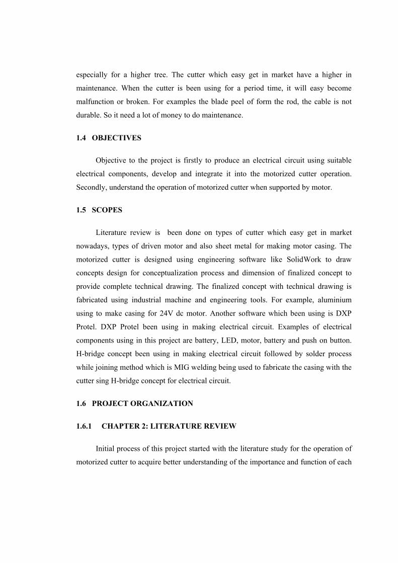
2.2.1 Wilkinsword Telescopic Universal Cutter
Figure 2.1: Wilkinsword Telescopic Universal Cutter
The Wilkinsword Telescopic Universal Cutter have a few advantages. A top pruner of
this cutter is mounted on a lightweight telescopic steel pole that is capable of extending
up to 4metres. The bypass blades function via a gear action giving 3 times more cutting
power and operate through an integral pulley mechanism. The head can pivot through
240° and can lock at any angle.
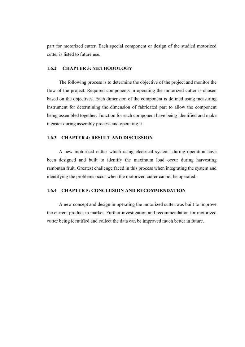
2.2.2 Telescopic Tree Pruner
Figure 2.2: Telescopic Tree Pruner
Telescopic Tree Pruner is made using 65Mn high carbon alloy steel saw blade
which durable when using it. The blade has 300mm and 2 sided teeth which allow
smoothly cutting. It has ground universal pull cut saw blade. The Telescopic Tree
Pruner are using double pulley with a 550lb. burst strength rope. Pulley is use in
reducing the cutting efforts. It also use Teflon blade coating to reduces cutting friction
and resists rust. The handles also can be adjustable. It just need to revolve the handles if
want to release or lock the handles. The handles made form strong extendable handles
and can be use for trimming branches up to 14’’ without a ladder. The connector made
using strong ABS plastic which also durable and can be use for a long term. Overall
length for this Telescopic Tree Pruner is 1800mm-2800mm.
2.2.3 Fiskars Pruner
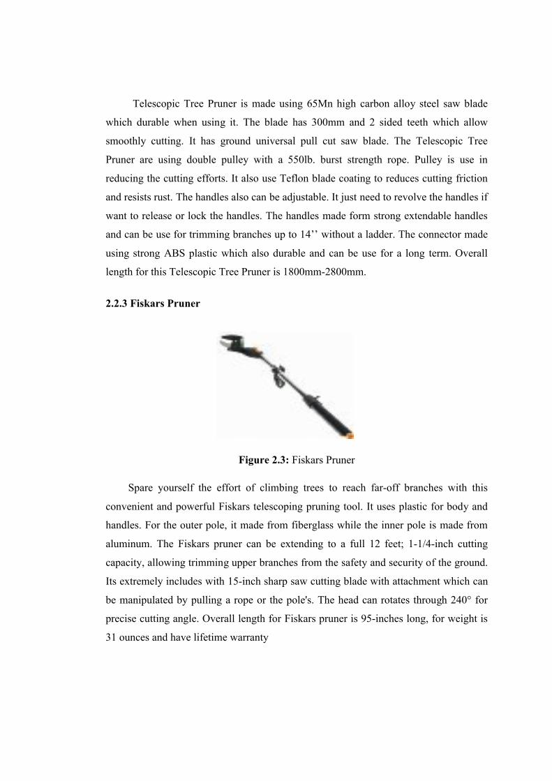
Figure 2.3: Fiskars Pruner
Spare yourself the effort of climbing trees to reach far-off branches with this
convenient and powerful Fiskars telescoping pruning tool. It uses plastic for body and
handles. For the outer pole, it made from fiberglass while the inner pole is made from
aluminum. The Fiskars pruner can be extending to a full 12 feet; 1-1/4-inch cutting
capacity, allowing trimming upper branches from the safety and security of the ground.
Its extremely includes with 15-inch sharp saw cutting blade with attachment which can
be manipulated by pulling a rope or the pole's. The head can rotates through 240° for
precise cutting angle. Overall length for Fiskars pruner is 95-inches long, for weight is
31 ounces and have lifetime warranty
2.3 TYPES OF MOTOR DRIVE
2.3.1 AC INDUCTION MOTOR (SHADED POLE)
A shaded-pole motor is a type of AC single-phase induction motor. As in other
induction motors the rotating part is a squirrel-cage rotor. All single-phase motors
require a means of producing a rotating magnetic field for starting. In the shaded-pole
type, a part of the face of each field pole carries a copper ring called a shading coil.
Currents in this coil delay the phase of magnetic flux in that part of the pole enough to
provide a rotating field. The effect produces only a low starting torque compared to
other classes of single-phase motors.
These motors have only one winding, no capacitor nor starting switch, making
them economical and reliable. Because their starting torque is low they are best suited
to driving fans or other loads that are easily started. Moreover, they are compatible with
triac-based variable-speed controls, which often are used with fans. They are built in
power sizes up to about 1/6 hp or 125 watts output. For larger motors, other designs
offer better characteristics.
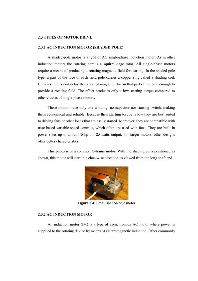
This photo is of a common C-frame motor. With the shading coils positioned as
shown, this motor will start in a clockwise direction as viewed from the long shaft end.
Figure 2.4: Small shaded-pole motor
2.3.2 AC INDUCTION MOTOR
An induction motor (IM) is a type of asynchronous AC motor where power is
supplied to the rotating device by means of electromagnetic induction. Other commonly