Embed Size (px)
Citation preview
Development of a new MeV gamma-ray camera
Atsushi TakedaH. Kubo, K. Miuchi, T. Nagayoshi,
Y. Okada, R. Orito, A. Takada, T. Tanimori, M. Ueno
Kyoto University
1. MeV Gamma-ray Astronomy2. New MeV Gamma-ray Camera3. Prototype Detector4. Summary & Future Works
ICEPP Symposium February 16, 2004 Hakuba, Nagano, Japan

our goal
high
sens
itivi
ty
1. MeV Gamma-ray Astronomy

Expected sources in MeV region•• Supernova Remnants (Supernova Remnants (SNRsSNRs))
•• Active Galactic Nuclei (AGN) jetsActive Galactic Nuclei (AGN) jets
•• Black HoleBlack Hole
•• Gamma Ray BurstsGamma Ray Bursts
•• PulsarsPulsars
26Al(1.8MeV), 44Ti(1.16MeV), Nuclear gamma
Optical Violent Variable (OVV) galaxy, Blazar
Binaries, Galactic Center, Primordial BH, 511keV
Polarization

Mev γ-ray imaging detectors1. Collimator +
Position Sensitive Detector (PSD)
2. Single or Multiple Compton (Classical Compton Method)
3. Advanced Compton Method
PSD
sourcesource
Low-Z
High-Z
Single Compton
Narrow field of viewBackground from collimatorEnergy < 1MeV
Only event circleNo background rejection
Full event reconstructionKinematical background rejectionLarge field of view
semiconductor
Multiple Compton
TPC
High-Z
e-
γ
COMPTEL
MeV gamma-ray camera

COMPTEL (aboard CGRO satellite: 1991~2000)
E0
φ
E1
E2
Classical Compton methodClassical Compton method
NaI(Tl)
liquid scintillator(NE213)
•• energies of scattered energies of scattered γγ and and recoil erecoil e-- : : EE11 , , EE22
•• positions where scattering positions where scattering and and γγ absorption occurred absorption occurred
E0 , φ
event axis direction
event axis
Only event circle can be determinedNo background rejection

2. New MeV Gamma-ray Camera
e -
e -e+
Drift plane
~1MeVγ~10MeVγ
μμ--PICPIC
Scintillator
PMTs
Event by event full reconstruction
•• micromicro--TPC (TPC (µ --PIC + TPC)PIC + TPC)
•• Scintillation cameraScintillation camera
recoil electron energy & track+
scattered γ energy & position
•• large field of viewlarge field of view
•• αα ⇒⇒ background rejectionbackground rejection
Advanced Compton methodAdvanced Compton method

Micro PIxel gas Chamber (µ-PIC)
CathodeAnode
400µm
100µm
50µm
•• High gain > High gain > 101044
•• Fine position resolution ~Fine position resolution ~120120µµmm
•• Discharge damage is not seriousDischarge damage is not serious
CathodeAnode
10cm
10cm
•• 400400µm pitch electrodespitch electrodes
•• 256256 anodes andanodes and 256256 cathodescathodes
•• Printed Circuit Board (Printed Circuit Board (PCBPCB))technology
Key device for the recoil electron tracking
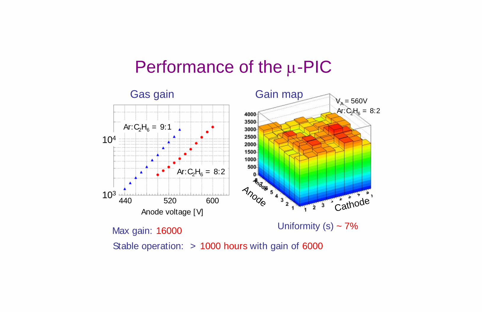
Uniformity (s) ~ 7%
Gain map
CathodeAnode
VA = 560V
Performance of the µ-PIC Gas gain
440 600520Anode voltage [V]
104
103
Ar:C2H6 = 8:2
Ar:C2H6 = 9:1
Ar:C2H6 = 8:2
Max gain: 16000
Stable operation: > 1000 hours with gain of 6000

Performance of the µ-PIC
Energy [keV]0 1 2 3 4 5 6 7 8 9 10
Cou
nts
0
50
100
150
200
250
300
23% (FWHM)
Mn Kα5.9keV
Ar escape
Cou
nts
Energy [keV] Energy [keV]
30% (FWHM)
Cou
nts
(10×10cm2 , whole area)55Fe energy spectrum
(12.8×12.8mm2)

X-ray images obtained with µ-PIC
position resolution σ=120µm
0.5mm
probe
banana plug
Length along the edge [mm]C
ount
s
Knife edge test
Xe:C2 H6 = 7:3
Test chart image
slits

•• Amp boardsAmp boards•• AmplifierAmplifier--shapershaper--
discriminator (ASD) chipdiscriminator (ASD) chip•• discrimination discrimination →→ digital outdigital out
Micro-TPC
•• EncoderEncoder•• FPGA X 5FPGA X 5•• 20MHz clock20MHz clock
•• μμ--PICPIC•• 10cm X 10cm10cm X 10cm
•• TPCTPC•• 8cm drift length8cm drift length
Picture of the micro-TPC
==μμ-PIC + TPC ⇒ 3D tracking(x, y) (drift time)

Tracking performance of the micro-TPC
3-D spatial resolution : 260µm(Ar, 20MHz clock)
Electron tracks Proton track 0.8 GeV/c2
proton beam
~500 keV/c2
electron tracks
(limited by DAQ clock of 20MHz)
~210µm using 50MHz DAQ in the near future

No Veto or Shield !
position resolution~6.7mm (FWHM)
energy resolution~11.2% (662keV, FWHM)
ASD chips
RI source
encoder
memoryboard
NaI(Tl) Anger camera
•• 10 X 10 X 8 cm10 X 10 X 8 cm33
•• Ar + CAr + C22 HH66 (9:1)(9:1)
•• 10 X 10 X 2.5 cm10 X 10 X 2.5 cm33
•• 25 PMTs25 PMTs
3. Prototype Detector Micro-TPC (µ-PIC)

Typical reconstructed event
NaI hit
Signal wave forms
Top view
Side view
source positionreconstructedCompton pointNaI hit

Gamma-ray imaging for known energysources
from track of recoiled e- + energy and direction of scattered γ
137Cs 662keV 22Na 511keV 133Ba 356keV
Angular resolution (RMS:662keV)
Angular Resolution Measure (ARM): ~15°
src src src-15 15 15-15
-15
15 15
-15
15
15-15-15X [cm] X [cm]X [cm]
Y [c
m]
Y [c
m]
Y [c
m]
Scatter Plane Deviation (SPD): ~25°

No cut
After α cut
SPD
0° 180°-180°
ARM
0° 180°-180°
Background rejection
0° 45°-45°
αgeo-αkin
αgeo : measured ααkin : calculated α from
energy information
αgeo~αkin
cut
cut
source
source
-15-15
15
15
X [cm]
Y [c
m]
-15-15
15X [cm]
15
Y [c
m]Incident γ
scattered γ
recoil e-
α cut
using redundantangle “α”
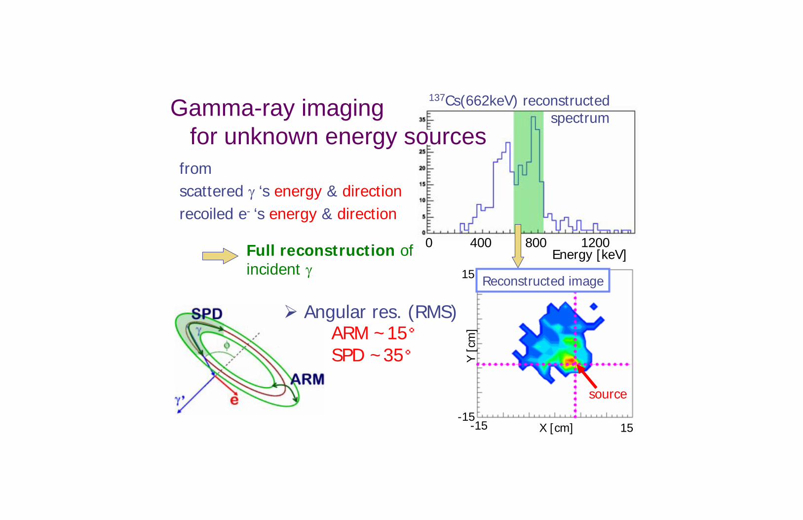
0 400 800 1200Energy [keV]
137Cs(662keV) reconstructed spectrum
source
fromscattered γ ‘s energy & directionrecoiled e- ‘s energy & direction
Full reconstruction ofincident γ
Reconstructed image
-15 15-15
15
X [cm]
Y [c
m]
Angular res. (RMS)ARM ~15°SPD ~35°
Gamma-ray imagingfor unknown energy sources

150 events
Comparison with the classical Compton method
Advanced Compton Meth. Classical Compton Meth.
600 events
Using the electron tracks• complete direction withinsector form error region
• only event circle withinring form error region
-15-15
15
15
X [cm]
Y [c
m]
-15-15
15X [cm]
15
Y [c
m]
Not using the electron tracks
2 sources wereseparated clearlyeven from ~100 events
Hard to separate 2 sources

4. Summary & Future worksEvent by event full reconstruction well established⇒ even for the continuous γ-ray
Good background rejection capability⇒ higher S/N than that of classical Compton
Prototype performance (full reconstruction)
• ARM(RMS) ~15°• SPD(RMS) ~35°
ARM (goal: σ~3°)
• uniformity of micro-TPChigher energy resolution
• pixelization of scintillatorhigher position resolution
SPD (goal: σ~5°)• clock up of micro-TPC
(20MHz→50MHz)• gas study (Ar→CF4)• large volume micro-TPC
more precise tracking


Crystal structure analysis with RCP* method*RCP: Rotation Continuous Photograph
Experimental setup @TIT
X-ray generator 50kV, 250mAMo target 17keV
Crystals
(λ : 0.071 nm)
10X10cm
Goniometer
Beam stopper
Sample crystal
Beam line
µ-PIC

Clock up of the micro-TPC
Clock up
20MHz(proton) 50MHz(proton)
Gaps in the drift direction:2mm :0.8mm
More precise tracking ofrecoiled electron
Higher spatial resolutionof micro-TPC

Theoretical limits of angular resolutionin the ARM direction
0.9゜0.4゜0.8゜0.5゜1MeV1.6゜0.8゜1.5゜1.1゜500keV3.5゜1.8゜3.3゜2.6゜200keVCdTeSiXeAr
Angular resolutions (ARM) for various nucleiA.Zoglauer, et.al.(SPIE,2003)
Owing to the Doppler broadening of the scattered g-ray energy
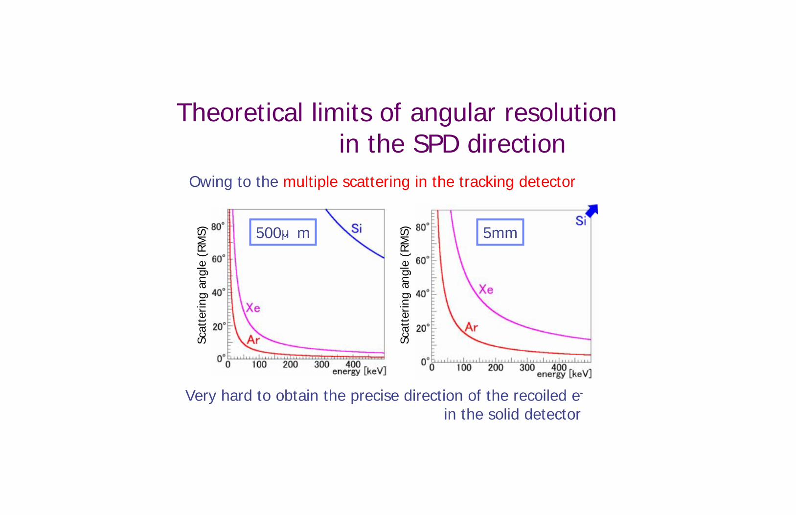
Owing to the multiple scattering in the tracking detector
500μm
Scat
terin
g an
gle
(RM
S)
Very hard to obtain the precise direction of the recoiled e-
in the solid detector
5mm
Scat
terin
g an
gle
(RM
S)
Theoretical limits of angular resolutionin the SPD direction

Effective area
1 10 10210-1
Energy [MeV]
10-1
1
10
10-2
Prob
abili
ty [
%]
Gas thickness: 50cm
Effective area of COMPTEL~40cm2 @ 1MeV
50cm cube gas detectorCompton effective area
~30cm2 @ 1MeV (Xe 1atm)
Gas detector has enough Compton scattering capability
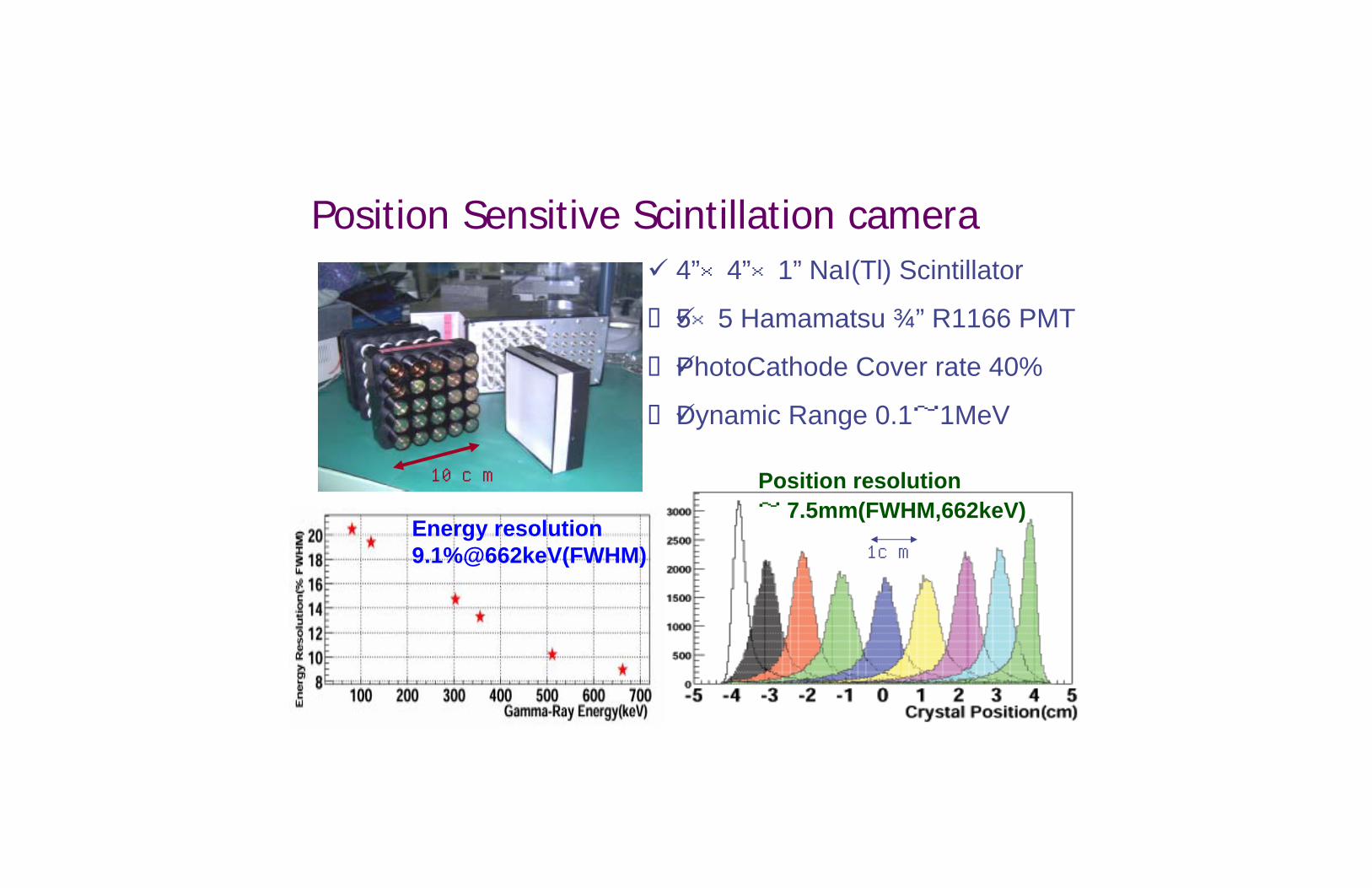
Position Sensitive Scintillation camera4”×4”×1” NaI(Tl) Scintillator
5×5 Hamamatsu ¾” R1166 PMT
PhotoCathode Cover rate 40%
Dynamic Range 0.1~1MeV
10cm
1cm
Position resolution~ 7.5mm(FWHM,662keV)
Energy resolution 9.1%@662keV(FWHM)

50cm3 Xe1.5atm50cm3 Ar 3atm30cm3 Xe 1.5 atm30cm3 Ar 3atm
Zenith Angle =0°
Detection Efficiency
Through going electron (δ also improved)30cm3 Xe 1.5 atm
All scattered γ
γ
e- γ’Gas
Silicon pad

30cm×30cm µ-PIC
Now, we are developing 30×30cm2 µ-PIC.

Electronics
30cm
40cm
μ-PIC
Encoding board5 FPGAstake anode–cathodecoincidence @ 20MHz
PreamplifierATLAS ASD chip

Angular Resolution ARM : Angular Resolution MeasureSPD : Scatter Plane Deviation
ARM
SPD
30cm Xe 1.5 atm
Effective Area
Scintillator
θ
Gas
Large field of view ~2str(FWHM)
30cm Xe 1.5 atm(1MeV)
@FWHM